KR102113853B1 - Method and aparatus of detecting coupling region - Google Patents
Method and aparatus of detecting coupling regionDownload PDFInfo
- Publication number
- KR102113853B1 KR102113853B1KR1020130084194AKR20130084194AKR102113853B1KR 102113853 B1KR102113853 B1KR 102113853B1KR 1020130084194 AKR1020130084194 AKR 1020130084194AKR 20130084194 AKR20130084194 AKR 20130084194AKR 102113853 B1KR102113853 B1KR 102113853B1
- Authority
- KR
- South Korea
- Prior art keywords
- wireless power
- resonator
- coupling
- power transmission
- received
- Prior art date
- Legal status (The legal status is an assumption and is not a legal conclusion. Google has not performed a legal analysis and makes no representation as to the accuracy of the status listed.)
- Active
Links
Images


Classifications
- H—ELECTRICITY
- H04—ELECTRIC COMMUNICATION TECHNIQUE
- H04B—TRANSMISSION
- H04B5/00—Near-field transmission systems, e.g. inductive or capacitive transmission systems
- H04B5/70—Near-field transmission systems, e.g. inductive or capacitive transmission systems specially adapted for specific purposes
- H04B5/79—Near-field transmission systems, e.g. inductive or capacitive transmission systems specially adapted for specific purposes for data transfer in combination with power transfer
- B—PERFORMING OPERATIONS; TRANSPORTING
- B60—VEHICLES IN GENERAL
- B60L—PROPULSION OF ELECTRICALLY-PROPELLED VEHICLES; SUPPLYING ELECTRIC POWER FOR AUXILIARY EQUIPMENT OF ELECTRICALLY-PROPELLED VEHICLES; ELECTRODYNAMIC BRAKE SYSTEMS FOR VEHICLES IN GENERAL; MAGNETIC SUSPENSION OR LEVITATION FOR VEHICLES; MONITORING OPERATING VARIABLES OF ELECTRICALLY-PROPELLED VEHICLES; ELECTRIC SAFETY DEVICES FOR ELECTRICALLY-PROPELLED VEHICLES
- B60L53/00—Methods of charging batteries, specially adapted for electric vehicles; Charging stations or on-board charging equipment therefor; Exchange of energy storage elements in electric vehicles
- B60L53/10—Methods of charging batteries, specially adapted for electric vehicles; Charging stations or on-board charging equipment therefor; Exchange of energy storage elements in electric vehicles characterised by the energy transfer between the charging station and the vehicle
- B60L53/12—Inductive energy transfer
- B—PERFORMING OPERATIONS; TRANSPORTING
- B60—VEHICLES IN GENERAL
- B60L—PROPULSION OF ELECTRICALLY-PROPELLED VEHICLES; SUPPLYING ELECTRIC POWER FOR AUXILIARY EQUIPMENT OF ELECTRICALLY-PROPELLED VEHICLES; ELECTRODYNAMIC BRAKE SYSTEMS FOR VEHICLES IN GENERAL; MAGNETIC SUSPENSION OR LEVITATION FOR VEHICLES; MONITORING OPERATING VARIABLES OF ELECTRICALLY-PROPELLED VEHICLES; ELECTRIC SAFETY DEVICES FOR ELECTRICALLY-PROPELLED VEHICLES
- B60L53/00—Methods of charging batteries, specially adapted for electric vehicles; Charging stations or on-board charging equipment therefor; Exchange of energy storage elements in electric vehicles
- B60L53/30—Constructional details of charging stations
- B60L53/35—Means for automatic or assisted adjustment of the relative position of charging devices and vehicles
- B60L53/36—Means for automatic or assisted adjustment of the relative position of charging devices and vehicles by positioning the vehicle
- B—PERFORMING OPERATIONS; TRANSPORTING
- B60—VEHICLES IN GENERAL
- B60L—PROPULSION OF ELECTRICALLY-PROPELLED VEHICLES; SUPPLYING ELECTRIC POWER FOR AUXILIARY EQUIPMENT OF ELECTRICALLY-PROPELLED VEHICLES; ELECTRODYNAMIC BRAKE SYSTEMS FOR VEHICLES IN GENERAL; MAGNETIC SUSPENSION OR LEVITATION FOR VEHICLES; MONITORING OPERATING VARIABLES OF ELECTRICALLY-PROPELLED VEHICLES; ELECTRIC SAFETY DEVICES FOR ELECTRICALLY-PROPELLED VEHICLES
- B60L53/00—Methods of charging batteries, specially adapted for electric vehicles; Charging stations or on-board charging equipment therefor; Exchange of energy storage elements in electric vehicles
- B60L53/30—Constructional details of charging stations
- B60L53/35—Means for automatic or assisted adjustment of the relative position of charging devices and vehicles
- B60L53/38—Means for automatic or assisted adjustment of the relative position of charging devices and vehicles specially adapted for charging by inductive energy transfer
- B—PERFORMING OPERATIONS; TRANSPORTING
- B60—VEHICLES IN GENERAL
- B60L—PROPULSION OF ELECTRICALLY-PROPELLED VEHICLES; SUPPLYING ELECTRIC POWER FOR AUXILIARY EQUIPMENT OF ELECTRICALLY-PROPELLED VEHICLES; ELECTRODYNAMIC BRAKE SYSTEMS FOR VEHICLES IN GENERAL; MAGNETIC SUSPENSION OR LEVITATION FOR VEHICLES; MONITORING OPERATING VARIABLES OF ELECTRICALLY-PROPELLED VEHICLES; ELECTRIC SAFETY DEVICES FOR ELECTRICALLY-PROPELLED VEHICLES
- B60L53/00—Methods of charging batteries, specially adapted for electric vehicles; Charging stations or on-board charging equipment therefor; Exchange of energy storage elements in electric vehicles
- B60L53/60—Monitoring or controlling charging stations
- B60L53/62—Monitoring or controlling charging stations in response to charging parameters, e.g. current, voltage or electrical charge
- H—ELECTRICITY
- H02—GENERATION; CONVERSION OR DISTRIBUTION OF ELECTRIC POWER
- H02J—CIRCUIT ARRANGEMENTS OR SYSTEMS FOR SUPPLYING OR DISTRIBUTING ELECTRIC POWER; SYSTEMS FOR STORING ELECTRIC ENERGY
- H02J50/00—Circuit arrangements or systems for wireless supply or distribution of electric power
- H02J50/10—Circuit arrangements or systems for wireless supply or distribution of electric power using inductive coupling
- H02J50/12—Circuit arrangements or systems for wireless supply or distribution of electric power using inductive coupling of the resonant type
- H—ELECTRICITY
- H02—GENERATION; CONVERSION OR DISTRIBUTION OF ELECTRIC POWER
- H02J—CIRCUIT ARRANGEMENTS OR SYSTEMS FOR SUPPLYING OR DISTRIBUTING ELECTRIC POWER; SYSTEMS FOR STORING ELECTRIC ENERGY
- H02J50/00—Circuit arrangements or systems for wireless supply or distribution of electric power
- H02J50/40—Circuit arrangements or systems for wireless supply or distribution of electric power using two or more transmitting or receiving devices
- H02J50/402—Circuit arrangements or systems for wireless supply or distribution of electric power using two or more transmitting or receiving devices the two or more transmitting or the two or more receiving devices being integrated in the same unit, e.g. power mats with several coils or antennas with several sub-antennas
- H—ELECTRICITY
- H02—GENERATION; CONVERSION OR DISTRIBUTION OF ELECTRIC POWER
- H02J—CIRCUIT ARRANGEMENTS OR SYSTEMS FOR SUPPLYING OR DISTRIBUTING ELECTRIC POWER; SYSTEMS FOR STORING ELECTRIC ENERGY
- H02J50/00—Circuit arrangements or systems for wireless supply or distribution of electric power
- H02J50/80—Circuit arrangements or systems for wireless supply or distribution of electric power involving the exchange of data, concerning supply or distribution of electric power, between transmitting devices and receiving devices
- H—ELECTRICITY
- H04—ELECTRIC COMMUNICATION TECHNIQUE
- H04W—WIRELESS COMMUNICATION NETWORKS
- H04W52/00—Power management, e.g. Transmission Power Control [TPC] or power classes
- H04W52/04—Transmission power control [TPC]
- H04W52/18—TPC being performed according to specific parameters
- H04W52/28—TPC being performed according to specific parameters using user profile, e.g. mobile speed, priority or network state, e.g. standby, idle or non-transmission
- H04W52/285—TPC being performed according to specific parameters using user profile, e.g. mobile speed, priority or network state, e.g. standby, idle or non-transmission taking into account the mobility of the user
- H—ELECTRICITY
- H02—GENERATION; CONVERSION OR DISTRIBUTION OF ELECTRIC POWER
- H02J—CIRCUIT ARRANGEMENTS OR SYSTEMS FOR SUPPLYING OR DISTRIBUTING ELECTRIC POWER; SYSTEMS FOR STORING ELECTRIC ENERGY
- H02J50/00—Circuit arrangements or systems for wireless supply or distribution of electric power
- H02J50/90—Circuit arrangements or systems for wireless supply or distribution of electric power involving detection or optimisation of position, e.g. alignment
- H—ELECTRICITY
- H04—ELECTRIC COMMUNICATION TECHNIQUE
- H04B—TRANSMISSION
- H04B5/00—Near-field transmission systems, e.g. inductive or capacitive transmission systems
- H04B5/20—Near-field transmission systems, e.g. inductive or capacitive transmission systems characterised by the transmission technique; characterised by the transmission medium
- H04B5/24—Inductive coupling
- Y—GENERAL TAGGING OF NEW TECHNOLOGICAL DEVELOPMENTS; GENERAL TAGGING OF CROSS-SECTIONAL TECHNOLOGIES SPANNING OVER SEVERAL SECTIONS OF THE IPC; TECHNICAL SUBJECTS COVERED BY FORMER USPC CROSS-REFERENCE ART COLLECTIONS [XRACs] AND DIGESTS
- Y02—TECHNOLOGIES OR APPLICATIONS FOR MITIGATION OR ADAPTATION AGAINST CLIMATE CHANGE
- Y02T—CLIMATE CHANGE MITIGATION TECHNOLOGIES RELATED TO TRANSPORTATION
- Y02T10/00—Road transport of goods or passengers
- Y02T10/60—Other road transportation technologies with climate change mitigation effect
- Y02T10/70—Energy storage systems for electromobility, e.g. batteries
- Y—GENERAL TAGGING OF NEW TECHNOLOGICAL DEVELOPMENTS; GENERAL TAGGING OF CROSS-SECTIONAL TECHNOLOGIES SPANNING OVER SEVERAL SECTIONS OF THE IPC; TECHNICAL SUBJECTS COVERED BY FORMER USPC CROSS-REFERENCE ART COLLECTIONS [XRACs] AND DIGESTS
- Y02—TECHNOLOGIES OR APPLICATIONS FOR MITIGATION OR ADAPTATION AGAINST CLIMATE CHANGE
- Y02T—CLIMATE CHANGE MITIGATION TECHNOLOGIES RELATED TO TRANSPORTATION
- Y02T10/00—Road transport of goods or passengers
- Y02T10/60—Other road transportation technologies with climate change mitigation effect
- Y02T10/7072—Electromobility specific charging systems or methods for batteries, ultracapacitors, supercapacitors or double-layer capacitors
- Y—GENERAL TAGGING OF NEW TECHNOLOGICAL DEVELOPMENTS; GENERAL TAGGING OF CROSS-SECTIONAL TECHNOLOGIES SPANNING OVER SEVERAL SECTIONS OF THE IPC; TECHNICAL SUBJECTS COVERED BY FORMER USPC CROSS-REFERENCE ART COLLECTIONS [XRACs] AND DIGESTS
- Y02—TECHNOLOGIES OR APPLICATIONS FOR MITIGATION OR ADAPTATION AGAINST CLIMATE CHANGE
- Y02T—CLIMATE CHANGE MITIGATION TECHNOLOGIES RELATED TO TRANSPORTATION
- Y02T90/00—Enabling technologies or technologies with a potential or indirect contribution to GHG emissions mitigation
- Y02T90/10—Technologies relating to charging of electric vehicles
- Y02T90/12—Electric charging stations
- Y—GENERAL TAGGING OF NEW TECHNOLOGICAL DEVELOPMENTS; GENERAL TAGGING OF CROSS-SECTIONAL TECHNOLOGIES SPANNING OVER SEVERAL SECTIONS OF THE IPC; TECHNICAL SUBJECTS COVERED BY FORMER USPC CROSS-REFERENCE ART COLLECTIONS [XRACs] AND DIGESTS
- Y02—TECHNOLOGIES OR APPLICATIONS FOR MITIGATION OR ADAPTATION AGAINST CLIMATE CHANGE
- Y02T—CLIMATE CHANGE MITIGATION TECHNOLOGIES RELATED TO TRANSPORTATION
- Y02T90/00—Enabling technologies or technologies with a potential or indirect contribution to GHG emissions mitigation
- Y02T90/10—Technologies relating to charging of electric vehicles
- Y02T90/14—Plug-in electric vehicles
- Y—GENERAL TAGGING OF NEW TECHNOLOGICAL DEVELOPMENTS; GENERAL TAGGING OF CROSS-SECTIONAL TECHNOLOGIES SPANNING OVER SEVERAL SECTIONS OF THE IPC; TECHNICAL SUBJECTS COVERED BY FORMER USPC CROSS-REFERENCE ART COLLECTIONS [XRACs] AND DIGESTS
- Y02—TECHNOLOGIES OR APPLICATIONS FOR MITIGATION OR ADAPTATION AGAINST CLIMATE CHANGE
- Y02T—CLIMATE CHANGE MITIGATION TECHNOLOGIES RELATED TO TRANSPORTATION
- Y02T90/00—Enabling technologies or technologies with a potential or indirect contribution to GHG emissions mitigation
- Y02T90/10—Technologies relating to charging of electric vehicles
- Y02T90/16—Information or communication technologies improving the operation of electric vehicles
Landscapes
- Engineering & Computer Science (AREA)
- Power Engineering (AREA)
- Computer Networks & Wireless Communication (AREA)
- Transportation (AREA)
- Mechanical Engineering (AREA)
- Signal Processing (AREA)
- Charge And Discharge Circuits For Batteries Or The Like (AREA)
Abstract
Translated fromKorean
Description
Translated fromKorean아래의 실시 예들은 무선 충전 시스템에 있어서, 최적의 커플링 영역을 검출하는 방법 및 장치에 관한 것이다.The following embodiments relate to a method and apparatus for detecting an optimal coupling area in a wireless charging system.
무선 전력전송에 대한 연구는 전기 자동차(electric vehicle) 및 휴대기기를 포함한 다양한 전기기기의 폭발적 증가로 인한 유선전력공급의 불편함 증가 및 기존 battery 용량의 한계 봉착 등을 극복하기 위해 시작되었다. 무선 전력 전송 기술들 중 하나는 RF 소자들의 공진(resonance) 특성을 이용한다. 공진 특성을 이용하는 무선 전력 전송 시스템은 전력을 공급하는 소스와 전력을 공급받는 타겟을 포함할 수 있다.Research on wireless power transmission has begun to overcome the inconvenience of wired power supply due to the explosive increase of various electric devices including electric vehicles and portable devices, and to overcome the limitations of existing battery capacity. One of the wireless power transmission technologies utilizes resonance characteristics of RF devices. A wireless power transmission system using a resonance characteristic may include a power supply source and a power supply target.
일 측면에 있어서, 무선 전력 송신 장치의 동작 방법은 무선 전력 수신 장치의 상태 정보를 수신하는 단계; 상기 무선 전력 수신 장치의 움직임에 따른 상기 상태 정보의 변화량을 계산하는 단계; 상기 변화량에 기초하여 상기 무선 전력 수신 장치의 커플링 영역 업데이트 정보를 생성하는 단계; 및 상기 수신 단계 내지 상기 생성 단계를 반복 수행하는 단계를 포함할 수 있다.In one aspect, the method of operation of the wireless power transmission apparatus comprises: receiving status information of the wireless power receiving apparatus; Calculating a change amount of the state information according to the movement of the wireless power receiving device; Generating coupling region update information of the wireless power receiver based on the amount of change; And repeating the receiving step to the generating step.
상기 무선 전력 수신 장치는 다른 무선 전력 송신 장치로부터 무선 전력을 수신하고, 수신된 무선 전력을 상기 전력 수신 장치로 송신하는 무선 전력 트랜시버일 수 있다.The wireless power receiving device may be a wireless power transceiver that receives wireless power from another wireless power transmitting device and transmits the received wireless power to the power receiving device.
다른 일 측면에 있어서, 무선 전력 송신 장치의 동작 방법은 상기 생성된 커플링 영역 업데이트 정보를 외부로 출력하는 단계를 더 포함할 수 있다.In another aspect, the method of operating the wireless power transmission apparatus may further include outputting the generated coupling area update information to the outside.
상기 외부로 출력하는 단계는, 상기 커플링 영역 업데이트 정보를 시각적, 촉각적, 또는 청각적 방식 중 어느 하나의 방식으로 출력하는 단계일 수 있다.The step of outputting to the outside may be a step of outputting the coupling region update information in any one of a visual, tactile, or audible manner.
상기 상태 정보는, 수신 전력, 임피던스, 수신 전압 또는 수신 전류 중 적어도 하나일 수 있다.The status information may be at least one of received power, impedance, received voltage, or received current.
다른 일 측면에 있어서, 무선 전력 송신 장치의 동작 방법은 상기 생성된 커플링 영역 업데이트 정보를 상기 무선 전력 수신 장치로 송신하는 단계를 더 포함하고, 상기 무선 전력 수신 장치는 상기 커플링 영역 업데이트 정보를 시각적, 촉각적, 또는 청각적 방식 중 어느 하나의 방식으로 사용자에게 피드백할 수 있다.In another aspect, a method of operating a wireless power transmission device further includes transmitting the generated coupling area update information to the wireless power reception device, wherein the wireless power reception device receives the coupling area update information. Feedback may be provided to the user in either a visual, tactile, or audible manner.
상기 무선 전력 송신 장치는 물리적으로 이격된 둘 이상의 공진기 및 상기 둘 이상의 공진기를 스위칭하는 스위칭 회로를 포함할 수 있고, 상기 생성된 커플링 영역 업데이트 정보에 따라 상기 스위칭 회로를 제어하는 단계를 더 포함할 수 있다.The wireless power transmission apparatus may include two or more resonators physically spaced apart and a switching circuit for switching the two or more resonators, and further comprising controlling the switching circuit according to the generated coupling region update information. Can be.
일 측면에 있어서, 무선 전력 송신 장치는 무선 전력 수신 장치의 상태 정보를 수신하는 통신부; 상기 무선 전력 수신 장치의 움직임에 따른 상기 상태 정보의 변화량을 계산하는 계산부; 상기 변화량에 기초하여 상기 무선 전력 수신 장치의 커플링 영역 업데이트 정보를 생성하는 정보 생성부; 및 상기 통신부, 계산부 및 정보 생성부의 동작이 반복하여 수행되도록 처리하는 처리부를 포함할 수 있다.In one aspect, the wireless power transmission apparatus includes a communication unit that receives status information of the wireless power reception apparatus; A calculator configured to calculate a change amount of the state information according to the movement of the wireless power receiving device; An information generator configured to generate coupling area update information of the wireless power receiver based on the amount of change; And it may include a processing unit for processing so that the operation of the communication unit, the calculation unit and the information generation unit is repeatedly performed.
상기 무선 전력 송신 장치는 물리적으로 이격된 둘 이상의 공진기 및 상기 둘 이상의 공진기를 스위칭하는 스위칭 회로를 포함할 수 있고, 상기 생성된 커플링 영역 업데이트 정보에 따라 상기 스위칭 회로를 제어하는 제어부를 더 포함할 수 있다.The wireless power transmission apparatus may include two or more resonators that are physically spaced apart and a switching circuit that switches the two or more resonators, and further include a control unit that controls the switching circuit according to the generated coupling region update information. You can.
다른 일 측면에 있어서, 무선 전력 송신 장치는 상기 생성된 커플링 영역 업데이트 정보를 외부로 출력하는 출력부를 더 포함할 수 있다.In another aspect, the wireless power transmission apparatus may further include an output unit that outputs the generated coupling region update information to the outside.
상기 출력부는, 상기 커플링 영역 업데이트 정보를 시각적, 촉각적, 또는 청각적 방식 중 어느 하나의 방식으로 출력할 수 있다.The output unit may output the coupling region update information in one of a visual, tactile, or audible manner.
상기 상태 정보는, 수신 전력, 임피던스, 수신 전압 또는 수신 전류 중 적어도 하나일 수 있다.The status information may be at least one of received power, impedance, received voltage, or received current.
일 측면에 있어서, 무선 전력 수신 장치는 무선 전력 송신 장치로부터 무선 전력을 수신하는 공진부; 상기 무선 전력 송신 장치로 상태 정보를 송신하고, 상기 무선 전력 송신장치로부터 커플링 영역 업데이트 정보를 수신하는 통신부; 및 상기 커플링 영역 업데이트 정보를 시각적, 촉각적, 또는 청각적 방식 중 어느 하나의 방식으로 사용자에게 피드백하는 출력부를 포함할 수 있고, 상기 커플링 영역 업데이트 정보는 상기 무선 전력 수신 장치의 움직임에 따른 상기 상태 정보의 변화량에 기초하여 생성될 수 있다.In one aspect, the wireless power receiving device includes a resonator for receiving wireless power from the wireless power transmitting device; A communication unit transmitting status information to the wireless power transmission apparatus and receiving coupling area update information from the wireless power transmission apparatus; And an output unit that feedbacks the coupling area update information to a user in one of a visual, tactile, or audible method, wherein the coupling area update information is generated according to the movement of the wireless power receiving device. It can be generated based on the amount of change in the state information.
상기 상태 정보는, 수신 전력, 임피던스, 수신 전압 또는 수신 전류 중 적어도 하나일 수 있다.The status information may be at least one of received power, impedance, received voltage, or received current.
도 1은 일 실시예에 따른 무선 전력 송수신 시스템을 나타낸다.
도 2는 일 실시예에 따른 공진기 및 피더에서 자기장의 분포를 나타낸다.
도 3은 일 실시예에 따른 공진기 및 피더의 구성을 나타낸 도면이다.
도 4는 일 실시예에 따른 피더의 피딩에 따른 공진기의 내부에서 자기장의 분포를 나타낸 도면이다.
도 5는 일 실시예에 따른 전기 자동차(electric vehicle) 충전 시스템을 나타낸다.
도 6은 커플링 영역 검출 시스템을 나타낸 도면이다.
도 7은 단말의 이동에 따른 커플링 영역 검출 시스템을 나타낸 도면이다.
도 8은 커플링 영역 검출을 위한 무선 전력 송신 장치의 동작 방법을 나타낸 플로우 차트이다.
도 9는 N개의 공진기를 구비한 무선 전력 송신 장치를 통해서 커플링 영역을 검출하는 시스템을 나타낸 도면이다.
도 10은 공진기 패드를 이용해서 커플링 영역을 검출하는 시스템을 나타낸 도면이다.
도 11은 공진기 패드의 이동에 따른 커플링 영역 검출 시스템을 나타낸 도면이다.
도 12는 무선 전력 송신 장치와 무선 전력 수신 장치를 나타낸 블록도이다.
도 13은 예시적인 실시 예에 따른 부하 검출 원리를 설명하기 위한 도면이다.
도 14는 무선 충전 패드가 내장된 무선 전력 송신 장치와 무선 전력 수신 장치를 나타낸 도면이다.1 shows a wireless power transmission and reception system according to an embodiment.
2 shows the distribution of a magnetic field in a resonator and feeder according to an embodiment.
3 is a view showing the configuration of a resonator and a feeder according to an embodiment.
4 is a view showing the distribution of a magnetic field inside the resonator according to the feeding of the feeder according to an embodiment.
5 shows an electric vehicle charging system according to an embodiment.
6 is a view showing a coupling area detection system.
7 is a view showing a coupling area detection system according to the movement of the terminal.
8 is a flowchart illustrating an operation method of a wireless power transmission apparatus for detecting a coupling region.
9 is a diagram illustrating a system for detecting a coupling region through a wireless power transmission device having N resonators.
10 is a view showing a system for detecting a coupling region using a resonator pad.
11 is a view showing a coupling area detection system according to the movement of the resonator pad.
12 is a block diagram showing a wireless power transmission device and a wireless power reception device.
Fig. 13 is a diagram for explaining the principle of load detection according to an exemplary embodiment.
14 is a view showing a wireless power transmitting apparatus and a wireless power receiving apparatus incorporating a wireless charging pad.
이하, 일측에 따른 실시예를 첨부된 도면을 참조하여 상세하게 설명한다.Hereinafter, embodiments according to one side will be described in detail with reference to the accompanying drawings.
도 1은 일 실시예에 따른 무선 전력 송수신 시스템을 나타낸다.1 shows a wireless power transmission and reception system according to an embodiment.
도 1을 참조하면, 일 실시 예에 따른 무선 전력 전송 시스템은 소스(110) 및 타겟(120)을 포함한다. 소스(110)는 무선 전력을 공급하는 디바이스를 의미하며, 디바이스에는 패드, 단말, TV, 의료기기, 전기 자동차(electric vehicle) 등 전력을 공급할 수 있는 모든 전자기기가 포함될 수 있다. 타겟(120)은 무선 전력을 공급받는 디바이스를 의미하며, 전력을 필요로 하는 모든 전자기기가 포함될 수 있다. 이때, 전자기기에는 패드, 단말, 태블릿, 의료기기, 전기 자동차(electric vehicle) 등이 포함될 수 있다.Referring to FIG. 1, a wireless power transmission system according to an embodiment includes a
소스(110)는 가변 SMPS(Variable SMPS)(111), 파워 증폭기(Power Amplifier)(112), 매칭 네트워크(113), 송신 제어부(114) 및 통신부(115)를 포함할 수 있다.
가변 SMPS(Variable SMPS, Variable Switching Mode Power Supply)(111)는 파워 공급기(Power Supply)로부터 출력되는 수십 Hz 대역의 AC 전압을 스위칭하여 DC 전압을 생성한다. 가변 SMPS(Variable SMPS)(111)는 일정한 레벨의 DC 전압을 출력하거나 송신 제어부(Tx Control Logic)(114)의 제어에 따라 DC 전압의 출력 레벨을 조정할 수 있다.Variable SMPS (Variable SMPS, Variable Switching Mode Power Supply) 111 generates a DC voltage by switching the AC voltage in the tens of Hz band output from the power supply. The variable SMPS (variable SMPS) 111 may output a DC voltage of a constant level or adjust the output level of the DC voltage under the control of the transmission control unit (Tx Control Logic) 114.
가변 SMPS(111)는 Class-E 타입의 파워 증폭기(Power Amplifier)(112)가 항상 효율이 높은 포화 영역에서 동작할 수 있도록, 파워 증폭기(Power Amplifier)(112)의 출력 전력 레벨에 따라 공급 전압을 제어하여, 모든 출력 레벨에서 최대효율을 유지하게 할 수 있다.The variable SMPS 111 is a supply voltage according to the output power level of the
가변 SMPS(111) 대신에 일반적으로 사용되는 상용 SMPS를 사용하는 경우에는, 추가적으로 가변 DC/DC(Variable DC/DC) 변환기를 사용한다. 상용 SMPS와 가변 DC/DC(Variable DC/DC)변환기는 Class-E 타입의 파워 증폭기(Power Amplifier)(112)가 항상 효율이 높은 포화 영역에서 동작할 수 있도록, 파워 증폭기(Power Amplifier)(112)의 출력 전력 레벨에 따라 공급 전압을 제어하여, 모든 출력 레벨에서 최대효율을 유지하게 할 수 있다.When a commercially available SMPS is used instead of the variable SMPS 111, a variable DC/DC (Variable DC/DC) converter is additionally used. Commercial SMPS and variable DC/DC (Variable DC/DC) converters allow the Class-E
파워 검출기(Power Detector)(116)는 가변 SMPS(Variable SMPS)(111)의 출력 전류 및 전압을 검출하고, 검출된 전류 및 전압에 대한 정보를 송신 제어부(114)로 전달할 수 있다. 또한, 파워 검출기(Power Detector)(116)는 파워 증폭기(Power Amplifier)(112)의 입력 전류 및 전압을 검출할 수도 있다.The
파워 증폭기(Power Amplifier)(112)는 수 MHz ~ 수십 MHz 대역의 스위칭 펄스 신호에 의하여 일정한 레벨의 DC 전압를 AC 전압으로 변환하여 전력을 생성할 수 있다. 즉, 파워 증폭기(Power Amplifier)(112)는 기준 공진 주파수 FRef를 이용하여 파워 증폭기(Power Amplifier)(112)에 공급되는 직류 전압을 교류 전압으로 변환하여, 복수의 타겟 디바이스들에서 사용되는 통신용 전력 또는 충전용 전력을 생성할 수 있다.The
수 킬로와트(kW)~수십 킬로와트에 해당하는 대 전력을 수십 KHz ~ 수백 KHz 대역의 공진 주파수를 이용하여 전송하는 경우에는 파워 증폭기(112)가 사용되지 않을 수 있다. 대신에 가변 SMPS(111) 또는 대전력 전원으로부터 전력이 소스 공진기(131)로 전달될 수 있다. 이 경우, 파워 증폭기(112) 대신 인버터가 사용될 수 있다. 인버터(inverter)는 대전력 전원으로부터 공급되는 직류 전력을 교류 전력으로 변환할 수 있다. 인버터는 수십 KHz ~ 수백 KHz 대역의 스위칭 펄스 신호에 의하여 일정한 레벨의 DC 전압을 AC 전압으로 변환하여 전력을 변환할 수 있다. 예를 들어, 인버터는 소스 공진기의 수십 KHz ~ 수백 KHz 대역의 공진 주파수를 이용하여 일정한 레벨의 DC 전압을 AC 전압으로 변환할 수 있다.When transmitting large powers corresponding to several kilowatts (kW) to tens of kilowatts using resonant frequencies in the tens of KHz to hundreds of KHz bands, the
여기서, 통신용 전력은 0.1~1mWatt의 작은 전력을 의미하고, 충전용 전력은 타겟 디바이스의 디바이스 로드에서 소비되는 수 밀리와트(mW)~수십 킬로와트(KW)의 큰 전력을 의미한다. 본 명세서에서, "충전"이라는 용어는 전력을 충전하는 유닛(unit) 또는 요소(element)에 전력을 공급하는 의미로 사용될 수 있다. 또한, "충전" 이라는 용어는 전력을 소비하는 유닛(unit) 또는 요소(element)에 전력을 공급하는 의미로도 사용될 수 있다. 여기서, 유닛(unit) 또는 요소(element)는 예를 들어 배터리, 디스플레이, 음성 출력 회로, 메인 프로세서, 각종 센서들을 포함할 수 있다.Here, the power for communication means a small power of 0.1 to 1 mWatt, and the power for charging means a large power of several milliwatts (mW) to tens of kilowatts (KW) consumed in the device load of the target device. In the present specification, the term “charge” may be used to mean supplying power to a unit or element charging power. In addition, the term "charge" may also be used to mean supplying power to a unit or element that consumes power. Here, a unit or element may include, for example, a battery, a display, an audio output circuit, a main processor, and various sensors.
한편, 본 명세서에서 "기준 공진 주파수"는 소스(110)가 기본적으로 사용하는 공진 주파수의 의미로 사용된다. 또한, "트래킹 주파수"는 기 설정된 방식에 따라 조정된 공진 주파수의 의미로 사용된다.Meanwhile, in the present specification, “reference resonance frequency” is used as a meaning of a resonance frequency basically used by the
송신 제어부(114)는 "통신용 전력" 또는 "충전용 전력"에 대한 반사파를 검출하고, 검출된 반사파에 기초하여 타겟 공진기(Target Resonator)(133)와 소스 공진기(Source Resonator)(131) 사이의 미스매칭(mismatching)을 검출한다. 송신 제어부(114)는 반사파의 포락선(envelop)을 검출하여 미스 매칭을 검출하거나, 반사파의 전력량을 검출하여 미스매칭을 검출할 수 있다.The
매칭 네트워크(113)는 송신 제어부(114)의 제어에 따라 소스 공진기(131)와 타겟 공진기(133) 간의 임피던스 미스매칭을 최적의 매칭으로 보상할 수 있다. 매칭 네트워크(113)는 캐패시터 또는 인덕터의 조합으로 송신 제어부(114)의 제어에 따라 스위치를 통해 연결될 수 있다.The
수십 KHz ~ 수백 KHz 대역의 공진 주파수를 이용하여 대전력을 전송하는 경우에는, 소스(110)에서 매칭 네트워크(113)의 구성이 생략될 수도 있다. 대전력의 전송 시에는 매칭 네트워크(113)의 영향이 감소할 수 있기 때문이다.When large power is transmitted by using a resonance frequency in a range of tens of KHz to hundreds of KHz, the configuration of the
송신 제어부(114)는 소스 공진기(131) 또는 파워 증폭기(Power Amplifier)(112)의 출력 전압의 레벨 및 상기 반사파의 전압 레벨에 기초하여 전압정재파비(VSWR, Voltage standing wave ratio)를 계산하고, 상기 전압정재파비가 기 설정된 값보다 커지면 상기 미스매칭이 검출된 것으로 결정할 수 있다.The
또한, 송신 제어부(114)는 상기 전압정재파비(VSWR)가 기 설정된 값보다 커지면 기 설정된 N개의 트래킹 주파수 각각에 대한 전력 전송 효율을 계산하고, 상기 N개의 트래킹주파수 중 전력 전송 효율이 가장 좋은 트래킹 주파수 FBest를 결정하고, 기준 공진 주파수 FRef를 상기 FBest로 조정할 수 있다.In addition, when the voltage standing wave ratio (VSWR) is greater than a preset value, the
또한, 송신 제어부(114)는 스위칭 펄스 신호의 주파수를 조정할 수 있다. 송신 제어부(114)의 제어에 의하여 스위칭 펄스 신호의 주파수가 결정될 수 있다. 송신 제어부(114)는 는 파워 증폭기(Power Amplifier)(112)를 제어함으로써, 타겟(120)에 전송하기 위한 변조 신호를 생성할 수 있다. 즉, 통신부(115)는 인-밴드 통신을 통해 타겟(120)과 다양한 데이터(140)를 전송할 수 있다. 또한, 송신 제어부(114)는 반사파를 검출하고, 반사파의 포락선을 통해 타겟(120)으로부터 수신되는 신호를 복조할 수 있다.Also, the
송신 제어부(114)는 다양한 방법을 통해, 인-밴드 통신을 수행하기 위한 변조 신호를 생성할 수 있다. 송신 제어부(114)는 스위칭 펄스 신호를 온/오프 하여, 변조신호를 생성할 수 있다. 또한, 송신 제어부(114)는 델타-시그마 변조를 수행하여, 변조신호를 생성할 수 있다. 송신 제어부(114)는 일정한 포락선을 가지는 펄스폭 변조신호를 생성할 수 있다.The
송신 제어부(114)는 소스(110)의 온도변화, 타겟(120)의 배터리 상태, 수신 전력량의 변화, 또는 타겟(120)의 온도 변화를 고려하여 타겟(120)으로 전송할 초기 무선 전력을 결정할 수 있다.The
소스(110)는 온도 변화를 감지하기 위한 온도 측정 센서(도시 되지 않음)를 더 포함할 수 있다. 타겟(120)의 배터리 상태, 수신 전력량의 변화, 또는 타겟(120)의 온도 변화에 대한 정보는 통신을 통해 타겟(120)으로부터 수신할 수 있다.The
즉, 타겟(120)의 온도 변화는 타겟(120)으로부터 수신된 데이터에 기초하여 검출될 수 있다.That is, the temperature change of the
이때, 송신 제어부(114)는 소스(110)의 온도의 변화에 따라 파워 증폭기(Power Amplifier)(112)로 공급되는 전압의 조정 량이 저장된 룩업-테이블을 이용하여 파워 증폭기(Power Amplifier)(112)로 공급되는 전압을 조정할 수 있다. 예를 들어, 소스(110)의 온도가 상승한 경우, 송신 제어부(114)는 파워 증폭기(Power Amplifier)(112)로 공급되는 전압을 낮출 수 있다.At this time, the
한편, 통신부(115)는 통신 채널을 이용하는 아웃-밴드 통신을 수행할 수도 있다. 통신부(115)는 지그비(Zigbee), 블루투스(Bluetooth) 등의 통신 모듈을 포함할 수 있다. 통신부(115)는 아웃-밴드 통신을 통해 타겟(120)과 데이터(140)를 전송할 수 있다.Meanwhile, the
소스 공진기(131)는 전자기(electromagnetic) 에너지(130)를 타겟 공진기(133)로 전달(transferring)한다. 소스 공진기(131)는 타겟 공진기(133)와의 마그네틱 커플링을 통해 "통신용 전력" 또는 "충전용 전력"을 타겟(120)으로 전달한다. 여기서, 소스 공진기(131)는 초전도체 물질로 구성될 수 있다. 또한, 도 1에서 도시되지는 않았지만 소스 공진기(131)가 초전도 성질을 유지하도록, 소스 공진기(131)는 냉각제를 포함하는 컨테이너에 위치할 수 있다. 가열된 냉각제는 냉각기에 의해 기체에서 액체로 액화될 수 있다. 다른 일예로, 타겟 공진기(133)가 초전도체 물질로 구성될 수도 있다. 이 경우 타겟 공진기(133)가 초전도 성질을 유지하도록 타겟 공진기(131)는 냉각제를 포함하는 컨테이너에 위치할 수 있다.The
타겟(120)은 매칭 네트워크(121), 정류부(122), DC/DC 컨버터(123), 통신부(124) 및 수신 제어부(Rx Control Logic)(125)를 포함할 수 있다.The
타겟 공진기(133)는 소스 공진기(131)로부터 전자기(electromagnetic) 에너지를 수신한다. 즉, 타겟 공진기(133)는 소스 공진기(131)와의 마그네틱 커플링을 통해 소스(110)로부터 "통신용 전력" 또는 "충전용 전력"을 수신할 수 있다. 또한, 타겟 공진기(133)는 인-밴드 통신을 통해 소스(110)로부터 다양한 데이터(140)를 수신할 수 있다.The
타겟 공진기(133)는 소스(110)의 온도변화, 타겟(120)의 배터리 상태, 수신 전력량의 변화, 또는 타겟(120)의 온도 변화를 고려하여 결정된 초기 무선 전력을 수신한다.The
매칭 네트워크(121)는 소스(110) 측으로 보이는 입력 임피던스와 부하(Load)측으로 보이는 출력 임피던스를 매칭시킬 수 있다. 매칭 네트워크(121)는 캐패시터와 인덕터의 조합으로 구성될 수 있다.The
정류부(122)는 교류 전압을 정류함으로써, DC 전압을 생성한다. 즉, 정류부(122)는 타겟 공진기(133)에 수신된 교류 전압을 정류할 수 있다.The rectifying
DC/DC 컨버터(123)는 정류부(122)에서 출력되는 DC 전압의 레벨을 Load에서 필요로 하는 용량에 맞게 조정한다. 예를 들어, DC/DC 컨버터(123)는 정류부(122)에서 출력되는 DC 전압의 레벨을 3~10Volt로 조정할 수 있다.The DC/
파워 검출기(Power Detector)(127)는 DC/DC 컨버터(123)의 입력단(126)의 전압과 출력단의 전류 및 전압을 검출할 수 있다. 검출된 입력단(126)의 전압은 소스에서 전달되는 전력의 전송 효율을 계산하는데 사용될 수 있다. 검출된 출력단의 전류 및 전압은 수신 제어부(Rx Control Logic)(125)가 로드(Load)에 전달되는 전력을 계산하는데 사용될 수 있다. 소스(110)의 송신 제어부(114)는 로드(Load)의 필요전력과 로드(Load)에 전달되는 전력을 고려하여, 소스(110)에서 전송해야 할 전력을 결정할 수 있다.The
통신부(124)를 통해 계산된 출력단의 전력이 소스(110)로 전달되면, 소스(110)는 전송해야 할 전력을 계산할 수 있다.When the power of the output terminal calculated through the
통신부(124)는 공진 주파수를 이용하여 데이터를 송수신하는 인-밴드 통신을 수행할 수 있다. 이때, 수신 제어부(125)는 타겟 공진기(133)과 정류부(122) 사이의 신호를 검출하여 수신 신호를 복조하거나, 정류부(122)의 출력 신호를 검출하여 수신 신호를 복조할 수 있다. 즉, 수신 제어부(125)는 인-밴드 통신을 통해 수신된 메시지를 복조할 수 있다. 또한, 수신 제어부(125)는 매칭 네트워크(121)를 통하여 타겟 공진기(133)의 임피던스를 조정함으로써, 소스(110)에 전송하는 신호를 변조할 수 있다. 간단한 예로, 수신 제어부(125)는 타겟 공진기(133)의 임피던스를 증가 시킴으로써, 소스(110)의 송신 제어부(114)에서 반사파가 검출되도록 할 수 있다. 반사파의 발생 여부에 따라, 소스(110)의 송신 제어부(114)는 제1 값(예를 들어, 이진수 "0" 또는 제2 값(예를 들어, 이진수 "1")을 검출할 수 있다.The
통신부(124)는 “해당 타겟의 제품의 종류”, “해당 타겟의 제조사 정보”, “해당 타겟의 모델명”, “해당 타겟의 배터리 유형(Battery type)”, “해당 타겟의 충전 방식”, “해당 타겟의 로드(Load)의 임피던스 값”, “해당 타겟의 타겟 공진기의 특성에 대한 정보”, “해당 타겟의 사용 주파수 대역에 대한 정보”, “해당 타겟의 소요되는 전력량”, “해당 타겟의 고유의 식별자” 및 “해당 타겟의 제품의 버전 또는 규격 정보”를 포함하는 응답 메시지를 소스(110)의 통신부(115)로 전송할 수 있다.The
한편, 통신부(124)는 통신 채널을 이용하는 아웃-밴드 통신을 수행할 수도 있다. 통신부(124)는 지그비(Zigbee), 블루투스(Bluetooth) 등의 통신 모듈을 포함할 수 있다. 통신부(124)는 아웃-밴드 통신을 통해 소스(110)와 데이터(140)를 송수신 할 수 있다.Meanwhile, the
통신부(124)는 소스(110)로부터 웨이크-업 요청 메시지를 수신하고, 파워 검출기(Power Detector)(127)는 타겟 공진기(133)에 수신되는 전력의 양을 검출하며, 통신부(124)는 타겟 공진기(133)에 수신되는 전력의 양에 대한 정보를 소스(110)로 전송할 수 있다. 이때, 타겟 공진기(133)에 수신되는 전력의 양에 대한 정보는, “정류부(122)의 입력 전압 값 및 전류 값”, “정류부(122)의 출력 전압 값 및 전류 값” 또는 “DC/DC 컨버터(123)의 출력 전압 값 및 전류 값”이다.
The
도 2 내지 도 4에서 "공진기"는 소스 공진기 및 타겟 공진기를 포함한다.2 to 4, the "resonator" includes a source resonator and a target resonator.
도 2는 일 실시예에 따른 공진기 및 피더에서 자기장의 분포를 나타낸다.2 shows the distribution of a magnetic field in a resonator and feeder according to an embodiment.
별도의 피더를 통해 공진기가 전력을 공급받는 경우에는 피더에서 자기장이 발생하고, 공진기에서도 자기장이 발생한다.When the resonator is supplied with power through a separate feeder, a magnetic field is generated in the feeder, and a magnetic field is also generated in the resonator.
소스 공진기 및 상기 타겟 공진기는 외부 루프 및 내부 루프로 구성되는 이중 루프 구조를 가지는The source resonator and the target resonator have a double loop structure composed of an outer loop and an inner loop
도 2의 (a)를 참조하면, 피더(210)에서 입력 전류가 흐름에 따라 자기장(230)이 발생한다. 피더(210) 내부에서 자기장의 방향(231)과 외부에서 자기장의 방향(233)은 서로 반대이다. 피더(210)에서 발생하는 자기장(1230)에 의해 공진기(220)에서 유도 전류가 발생한다. 이때 유도 전류의 방향은 입력 전류의 방향과 반대이다.Referring to (a) of FIG. 2, as the input current flows from the
유도 전류에 의해 공진기(220)에서 자기장(240)이 발생한다. 자기장의 방향은 공진기(220)의 내부에서는 동일한 방향을 가진다. 따라서, 공진기(220)에 의해 피더(210)의 내부에서 발생하는 자기장의 방향(241)과 피더(210)의 외부에서 발생하는 자기장의 방향(243)은 동일하다.The
결과적으로 피더(210)에 의해서 발생하는 자기장과 공진기(1220)에서 발생하는 자기장을 합성하면, 피더(210)의 내부에서는 자기장의 세기가 약화되고, 피더(210)의 외부에서는 자기장의 세기가 강화된다. 따라서, 도 2와 같은 구조의 피더(210)를 통해 공진기(220)에 전력을 공급하는 경우에, 공진기(220) 중심에서 자기장의 세기가 약하고, 외곽에서 자기장의 세기가 강하다. 공진기(220) 상에서 자기장의 분포가 균일(uniform)하지 않은 경우, 입력 임피던스가 수시로 변화하므로 임피던스 매칭을 수행하는 것이 어렵다. 또한, 자기장의 세기가 강한 부분에서는 무선 전력 전송이 잘되고, 자기장의 세기가 약한 부분에서는 무선 전력 전송이 잘 되지 않으므로, 평균적으로 전력 전송 효율이 감소한다.As a result, when the magnetic field generated by the
(b)는 공진기(250)와 피더(260)가 공통의 접지를 가진 무선 전력 전송 장치의 구조를 나타낸다. 공진기(250)는 캐패시터(251)를 포함할 수 있다. 피더(260)는 포트(261)를 통하여, RF 신호를 입력 받을 수 있다. 피더(260)에는 RF 신호가 입력되어, 입력 전류가 생성될 수 있다. 피더(260)에 흐르는 입력 전류는 자기장을 생성하고, 상기 자기장으로부터 공진기(250)에 유도 전류가 유도된다. 또한, 공진기(250)를 흐르는 유도 전류로부터 자기장이 발생한다. 이때, 피더(260)에 흐르는 입력 전류의 방향과 공진기(250)에 흐르는 유도 전류의 방향은 서로 반대 위상을 가진다. 따라서, 공진기(250)와 피더(260) 사이의 영역에서, 입력 전류에 의해 발생하는 자기장의 방향(271)과 유도 전류에 의해 발생하는 자기장의 방향(273)은 동일한 위상을 가지므로, 자기장의 세기가 강화된다. 피더(260)의 내부에서는, 입력 전류에 의해 발생하는 자기장의 방향(281)과 유도 전류에 의해 발생하는 자기장의 방향(283)은 반대 위상을 가지므로, 자기장의 세기가 약화된다. 결과적으로 공진기(250)의 중심에서는 자기장의 세기가 약해지고, 공진기(250)의 외곽에서는 자기장의 세기가 강화될 수 있다.(b) shows the structure of a wireless power transmission device in which the
피더(260)는 피더(260) 내부의 면적을 조절하여, 입력 임피던스를 결정할 수 있다. 여기서 입력 임피던스는 피더(260)에서 공진기(250)를 바라볼 때, 보이는 임피던스를 의미한다. 피더(260) 내부의 면적이 커지면 입력 임피던스는 증가하고, 내부의 면적이 작아지면 입력 임피던스는 감소한다. 그런데, 입력 임피던스가 감소하는 경우에도, 공진기(250) 내부의 자기장 분포는 일정하지 않으므로, 타겟 디바이스의 위치에 따라 입력 임피던스 값이 일정하지 않다. 따라서, 전력 증폭기의 출력 임피던스와 상기 입력 임피던스의 매칭을 위해 별도의 매칭 네트워크가 필요하다. 입력 임피던스가 증가하는 경우에는 큰 입력 임피던스를 작은 출력 임피던스에 매칭시키기 위해 별도의 매칭 네트워크가 필요할 수 있다.
The
도 3은 일 실시예에 따른 공진기 및 피더의 구성을 나타낸 도면이다.3 is a view showing the configuration of a resonator and a feeder according to an embodiment.
도 3의 (a)를 참조하면, 공진기(310)는 캐패시터(311)를 포함할 수 있다. 피딩부(320)는 캐패시터(311)의 양단에 전기적으로 연결될 수 있다.Referring to FIG. 3(a), the
(b)는 (a)의 구조를 좀 더 구체적으로 표시한 도면이다. 이때, 공진기(310)는 제1 전송선로, 제1 도체(341), 제2 도체(342), 적어도 하나의 제1 캐패시터(350)를 포함할 수 있다.(b) is a diagram more specifically showing the structure of (a). In this case, the
제1 캐패시터(350)는 제1 전송 선로에서 제1 신호 도체 부분(331)과 제2 신호 도체 부분(332) 사이에 위치에 직렬로 삽입되며, 그에 따라 전계(electric field)는 제1 캐패시터(350)에 갇히게 된다. 일반적으로, 전송 선로는 상부에 적어도 하나의 도체, 하부에 적어도 하나의 도체를 포함하며, 상부에 있는 도체를 통해서는 전류가 흐르며, 하부에 있는 도체는 전기적으로 그라운드 된다(grounded). 본 명세서에서는 제1 전송 선로의 상부에 있는 도체를 제1 신호 도체 부분(331)과 제2 신호 도체 부분(332)로 나누어 부르고, 제1 전송 선로의 하부에 있는 도체를 제1 그라운드 도체 부분(333)으로 부르기로 한다.The
(b)에 도시된 바와 같이, 공진기는 2 차원 구조의 형태를 갖는다. 제1 전송 선로는 상부에 제1 신호 도체 부분(331) 및 제2 신호 도체 부분(332)을 포함하고, 하부에 제1 그라운드 도체 부분(333)을 포함한다. 제1 신호 도체 부분(331) 및 제2 신호 도체 부분(332)과 제1 그라운드 도체 부분(333)은 서로 마주보게 배치된다. 전류는 제1 신호 도체 부분(331) 및 제2 신호 도체 부분(332)을 통하여 흐른다.As shown in (b), the resonator has the form of a two-dimensional structure. The first transmission line includes a first
또한, (b)에 도시된 바와 같이 제1 신호 도체 부분(331)의 한쪽 단은 제1 도체(341)와 접지(short)되고, 다른 쪽 단은 제1 캐패시터(350)와 연결된다. 그리고, 제2 신호 도체 부분(332)의 한쪽 단은 제2 도체(342)와 접지되며, 다른 쪽 단은 제1 캐패시터(350)와 연결된다. 결국, 제1 신호 도체 부분(331), 제2 신호 도체 부분(332) 및 제1 그라운드 도체 부분(333), 도체들(341, 342)은 서로 연결됨으로써, 공진기는 전기적으로 닫혀 있는 루프 구조를 갖는다. 여기서, '루프 구조'는 원형 구조, 사각형과 같은 다각형의 구조 등을 모두 포함하며, '루프 구조를 갖는다고 함은' 전기적으로 닫혀 있다는 것을 의미한다.Further, as shown in (b), one end of the first
제1 캐패시터(350)는 전송 선로의 중단부에 삽입된다. 보다 구체적으로, 제1캐패시터(350)는 제1 신호 도체 부분(331) 및 제2 신호 도체 부분(332) 사이에 삽입된다. 이 때, 제1 캐패시터(350)는 집중 소자(lumped element) 및 분산 소자(distributed element) 등의 형태를 가질 수 있다. 특히, 분산 소자의 형태를 갖는 분산된 캐패시터는 지그재그 형태의 도체 라인들과 그 도체 라인들 사이에 존재하는 높은 유전율을 갖는 유전체를 포함할 수 있다.The
제1 캐패시터(350)가 전송 선로에 삽입됨에 따라 소스 공진기는 메타물질(metamaterial)의 특성을 가질 수 있다. 여기서, 메타물질이란 자연에서 발견될 수 없는 특별한 전기적 성질을 갖는 물질로서, 인공적으로 설계된 구조를 갖는다. 자연계에 존재하는 모든 물질들의 전자기 특성은 고유의 유전율 또는 투자율을 가지며, 대부분의 물질들은 양의 유전율 및 양의 투자율을 갖는다.As the
대부분의 물질들에서 전계, 자계 및 포인팅 벡터에는 오른손 법칙이 적용되므로, 이러한 물질들을 RHM(Right Handed Material)이라고 한다. 그러나, 메타물질은 자연계에 존재하지 않는 유전율 또는 투자율을 가진 물질로서, 유전율 또는 투자율의 부호에 따라 ENG(epsilon negative) 물질, MNG(mu negative) 물질, DNG(double negative) 물질, NRI(negative refractive index) 물질, LH(left-handed) 물질 등으로 분류된다.In most materials, the right-hand law applies to electric field, magnetic field, and pointing vectors, so these materials are called RHM (Right Handed Material). However, metamaterial is a material having a dielectric constant or permeability that does not exist in nature, and according to the sign of permittivity or permeability, ENG (epsilon negative) material, MNG (mu negative) material, DNG (double negative) material, NRI (negative refractive index), LH (left-handed).
이 때, 집중 소자로서 삽입된 제1 캐패시터(350)의 캐패시턴스가 적절히 정해지는 경우, 소스 공진기는 메타물질의 특성을 가질 수 있다. 특히, 제1 캐패시터(350)의 캐패시턴스를 적절히 조절함으로써, 소스 공진기는 음의 투자율을 가질 수 있으므로, 소스 공진기는 MNG 공진기로 불려질 수 있다. 제1 캐패시터(350)의 캐패시턴스를 정하는 전제(criterion)들은 다양할 수 있다. 소스 공진기가 메타물질(metamaterial)의 특성을 가질 수 있도록 하는 전제(criterion), 소스 공진기가 대상 주파수에서 음의 투자율을 갖도록 하는 전제 또는 소스 공진기가 대상 주파수에서 영번째 공진(Zeroth-Order Resonance) 특성을 갖도록 하는 전제 등이 있을 수 있고, 상술한 전제들 중 적어도 하나의 전제 아래에서 제1 캐패시터(350)의 캐패시턴스가 정해질 수 있다.At this time, when the capacitance of the
MNG 공진기는 전파 상수(propagation constant)가 0일 때의 주파수를 공진 주파수로 갖는 영번째 공진(Zeroth-Order Resonance) 특성을 가질 수 있다. MNG 공진기는 영번째 공진 특성을 가질 수 있으므로, 공진 주파수는 MNG 공진기의 물리적인 사이즈에 대해 독립적일 수 있다. 즉, 아래에서 다시 설명하겠지만, MNG 공진기에서 공진 주파수를 변경하기 위해서는 제1 캐패시터(350)를 적절히 설계하는 것으로 충분하므로, MNG 공진기의 물리적인 사이즈를 변경하지 않을 수 있다.The MNG resonator may have a zero-order resonance characteristic having a frequency when the propagation constant is 0 as a resonance frequency. Since the MNG resonator may have a zeroth resonance characteristic, the resonant frequency may be independent of the physical size of the MNG resonator. That is, as will be described again below, in order to change the resonance frequency in the MNG resonator, it is sufficient to properly design the
또한, 근접장(near field)에서 전계는 전송 선로에 삽입된 제1 캐패시터(350)에 집중되므로, 제1 캐패시터(350)로 인하여 근접 필드에서는 자기장(magnetic field)이 도미넌트(dominant)해진다. 그리고, MNG 공진기는 집중 소자의 제1 캐패시터(350)를 이용하여 높은 큐-팩터(Q-Factor)를 가질 수 있으므로, 전력 전송의 효율을 향상시킬 수 있다. 참고로, 큐-팩터는 무선 전력 전송에 있어서 저항 손실(ohmic loss)의 정도 또는 저항(resistance)에 대한 리액턴스의 비를 나타내는데, 큐-팩터가 클수록 무선 전력 전송의 효율이 큰 것으로 이해될 수 있다.In addition, in the near field, the electric field is concentrated in the
또한, (b)에 도시되지 아니하였으나, MNG 공진기를 관통하는 마그네틱 코어가 더 포함될 수 있다. 이러한 마그네틱 코어는 전력 전송 거리를 증가시키는 기능을 수행할 수 있다.In addition, although not shown in (b), a magnetic core penetrating the MNG resonator may be further included. The magnetic core may function to increase the power transmission distance.
(b)를 참조하면, 피딩부(320)는 제2 전송선로, 제3 도체(371), 제4 도체(372), 제5 도체(381) 및 제6 도체(382)를 포함할 수 있다.Referring to (b), the
제2 전송 선로는 상부에 제3 신호 도체 부분(361) 및 제4 신호 도체 부분(362)을 포함하고, 하부에 제2 그라운드 도체 부분(363)을 포함한다. 제3 신호 도체 부분(361) 및 제4 신호 도체 부분(362)과 제2 그라운드 도체 부분(363)은 서로 마주보게 배치된다. 전류는 제3 신호 도체 부분(361) 및 제4 신호 도체 부분(362)을 통하여 흐른다.The second transmission line includes a third
또한, (b)에 도시된 바와 같이 제3 신호 도체 부분(361)의 한쪽 단은 제3 도체(371)와 접지(short)되고, 다른 쪽 단은 제5 도체(381)와 연결된다. 그리고, 제4 신호 도체 부분(362)의 한쪽 단은 제4 도체(372)와 접지되며, 다른 쪽 단은 제6 도체(382)와 연결된다. 제5 도체(381)는 제1 신호 도체 부분(331)과 연결되고, 제6 도체(382)는 제2 신호 도체 부분(332)과 연결된다. 제5 도체(381)와 제6 도체(382)는 제1 캐패시터(350)의 양단에 병렬로 연결된다. 이때, 제5 도체(381) 및 제6 도체(382)는 RF신호를 입력받는 입력 포트로 사용될 수 있다.Further, as shown in (b), one end of the third
결국, 제3 신호 도체 부분(361), 제4 신호 도체 부분(362) 및 제2 그라운드 도체 부분(363), 제3 도체(371), 제4 도체(372), 제5 도체(381), 제6 도체(382) 및 공진기(310)는 서로 연결됨으로써, 공진기(310) 및 피딩부(320)는 전기적으로 닫혀 있는 루프 구조를 갖는다. 여기서, '루프 구조'는 원형 구조, 사각형과 같은 다각형의 구조 등을 모두 포함한다. 제5 도체(381) 또는 제6 도체(382)를 통하여 RF 신호가 입력되면, 입력 전류는 피딩부(320) 및 공진기(310)에 흐르게 되고, 입력 전류에 의해 발생하는 자기장에 의하여, 공진기(310)에 유도 전류가 유도 된다. 피딩부(320)에서 흐르는 입력 전류의 방향과 공진기(310)에서 흐르는 유도 전류의 방향이 동일하게 형성됨으로써, 공진기(310)의 중앙에서는 자기장의 세기가 강화되고, 공진기(310)의 외곽에서는 자기장의 세기가 약화된다.As a result, the third
공진기(310)와 피딩부(320) 사이 영역의 면적에 의해 입력 임피던스가 결정될 수 있으므로, 전력 증폭기의 출력 임피던스와 상기 입력 임피던스의 매칭을 수행하기 위해 별도의 매칭 네트워크는 필요하지 않다. 매칭 네트워크가 사용되는 경우에도, 피딩부(320)의 크기를 조절함으로써, 입력 임피던스를 결정할 수 있기 때문에, 매칭 네트워크의 구조는 단순해질 수 있다. 단순한 매칭 네트워크 구조는 매칭 네트워크의 매칭 손실을 최소화한다.Since the input impedance may be determined by the area of the region between the
제2 전송 선로, 제3 도체(371), 제4 도체(372), 제5 도체(381), 제6 도체(382) 는 공진기(310)와 동일한 구조를 형성할 수 있다. 즉, 공진기(310)가 루프 구조인 경우에는 피딩부(320)도 루프 구조일 수 있다. 또한, 공진기(310)가 원형 구조인 경우에는 피딩부(320)도 원형 구조일 수 있다.
The second transmission line, the
도 4는 일 실시예에 따른 피더의 피딩에 따른 공진기의 내부에서 자기장의 분포를 나타낸 도면이다.4 is a view showing the distribution of a magnetic field inside the resonator according to the feeding of the feeder according to an embodiment.
무선 전력 전송에서 피딩은, 소스 공진기에 전력을 공급하는 것을 의미한다. 또한, 무선 전력 전송에서 피딩은, 정류부에 AC 전력을 공급하는 것을 의미할 수 있다. (a)는 피딩부에서 흐르는 입력 전류의 방향 및 소스 공진기에서 유도되는 유도 전류의 방향을 나타낸다. 또한, (a)는 피딩부의 입력 전류에 의해 발생하는 자기장의 방향 및 소스 공진기의 유도 전류에 의해 발생하는 자기장의 방향을 나타낸다. (a)는 도 3의 공진기(310) 및 피딩부(320)를 좀 더 간략하게 표현한 도면이다. (b)는 피딩부와 공진기의 등가회로를 나타낸다.In wireless power transmission, feeding means supplying power to a source resonator. Further, in wireless power transmission, feeding may mean supplying AC power to the rectifier. (a) shows the direction of the input current flowing in the feeding section and the direction of the induced current induced in the source resonator. In addition, (a) shows the direction of the magnetic field generated by the input current of the feeding part and the direction of the magnetic field generated by the induced current of the source resonator. (a) is a more simplified representation of the
(a)를 참조하면, 피딩부의 제5 도체 또는 제6 도체는 입력 포트(410)로 사용될 수 있다. 입력 포트(410)는 RF 신호를 입력 받는다. RF 신호는 전력 증폭기로부터 출력될 수 있다. 전력 증폭기는 타겟 디바이스의 필요에 따라 RF 신호의 진폭을 증감시킬 수 있다. 입력 포트(410)에서 입력된 RF 신호는 피딩부에 흐르는 입력 전류의 형태로 표시될 수 있다. 피딩부를 흐르는 입력 전류는 피딩부의 전송선로를 따라 시계방향으로 흐른다. 그런데, 피딩부의 제5 도체는 공진기와 전기적으로 연결된다. 좀 더 구체적으로, 제5 도체는 공진기의 제1 신호 도체 부분과 연결된다. 따라서 입력 전류는 피딩부 뿐만 아니라 공진기에도 흐르게 된다. 공진기에서 입력 전류는 반시계 방향으로 흐른다. 공진기에 흐르는 입력 전류에 의하여 자기장이 발생하고, 상기 자기장에 의해 공진기에 유도 전류가 생성된다. 유도 전류는 공진기에서 시계방향으로 흐른다. 이때 유도 전류는 공진기의 캐패시터에 에너지를 전달할 수 있다. 또한, 유도 전류에 의해 자기장이 발생한다. (a)에서 피딩부 및 공진기에 흐르는 입력 전류는 실선으로 표시되고, 공진기에 흐르는 유도 전류는 점선으로 표시되었다.Referring to (a), the fifth conductor or the sixth conductor of the feeding unit may be used as the
전류에 의해 발생하는 자기장의 방향은 오른나사의 법칙을 통해 알 수 있다. 피딩부 내부에서, 피딩부에 흐르는 입력 전류에 의해 발생한 자기장의 방향(421)과 공진기에 흐르는 유도 전류에 의해 발생한 자기장의 방향(423)은 서로 동일하다. 따라서, 피딩부 내부에서 자기장의 세기가 강화된다.The direction of the magnetic field generated by the current can be known through the law of the right screw. Inside the feeding portion, the
또한, 피딩부와 공진기 사이의 영역에서, 피딩부에 흐르는 입력 전류에 의해 발생한 자기장의 방향(433)과 소스 공진기에 흐르는 유도 전류에 의해 발생한 자기장의 방향(431)은 서로 반대이다. 따라서, 피딩부와 공진기 사이의 영역에서, 자기장의 세기는 약화된다.In the region between the feeding part and the resonator, the
루프 형태의 공진기에서는 일반적으로 공진기의 중심에서는 자기장의 세기가 약하고, 공진기의 외곽부분에서는 자기장의 세기가 강하다. 그런데 (a)를 참조하면, 피딩부가 공진기의 캐패시터 양단에 전기적으로 연결됨으로써 공진기의 유도 전류의 방향과 피딩부의 입력 전류의 방향이 동일해 진다. 공진기의 유도 전류의 방향과 피딩부의 입력 전류의 방향이 동일하기 때문에, 피딩부의 내부에서는 자기장의 세기가 강화되고, 피딩부의 외부에서는 자기장의 세기가 약화된다. 결과적으로 루프 형태의 공진기의 중심에서는 피딩부로 인하여 자기장의 세기가 강화되고, 공진기의 외곽부분에서는 자기장의 세기가 약화될 수 있다. 그러므로 공진기 내부에서는 전체적으로 자기장의 세기가 균일해질 수 있다.In the loop type resonator, the strength of the magnetic field is generally weak at the center of the resonator, and the strength of the magnetic field is strong at the outer portion of the resonator. However, referring to (a), since the feeding part is electrically connected to both ends of the capacitor of the resonator, the direction of the induced current of the resonator and the direction of the input current of the feeding part become the same. Since the direction of the induced current of the resonator and the direction of the input current of the feeding portion are the same, the strength of the magnetic field is enhanced inside the feeding portion, and the strength of the magnetic field is weakened outside the feeding portion. As a result, the strength of the magnetic field may be enhanced at the center of the loop type resonator due to the feeding portion, and the strength of the magnetic field may be weakened at the outer portion of the resonator. Therefore, the intensity of the magnetic field can be uniform throughout the resonator.
한편, 소스 공진기에서 타겟 공진기로 전달되는 전력 전송의 효율은 소스 공진기에서 발생하는 자기장의 세기에 비례하므로, 소스 공진기의 중심에서 자기장의 세기가 강화됨에 따라 전력 전송 효율도 증가할 수 있다.On the other hand, since the efficiency of power transmission from the source resonator to the target resonator is proportional to the intensity of the magnetic field generated by the source resonator, power transmission efficiency may also increase as the intensity of the magnetic field at the center of the source resonator is enhanced.
(b)를 참조하면, 피딩부(440) 및 공진기(450)는 등가회로로 표현될 수 있다. 피딩부(440)에서 공진기 측을 바라볼 때 보이는 입력 임피던스 Zin은 다음의 수식과 같이 계산될 수 있다.Referring to (b), the feeding

여기서, M은 피딩부(440)와 공진기(450) 사이의 상호 인덕턴스를 의미하고, ω 는 피딩부(440)와 공진기(450) 간의 공진 주파수를 의미하고, Z는 공진기(450)에서 타겟 디바이스 측을 바라볼 때 보이는 임피던스를 의미한다. Zin은 상호 인덕턴스 M에 비례한다. 따라서, 피딩부(440)와 공진기(450) 사이에 상호 인덕턴스를 조절함으로써 Zin을 제어할 수 있다. 상호 인덕턴스 M은 피딩부(440)와 공진기(450) 사이 영역의 면적에 따라 조절될 수 있다. 피딩부(440)의 크기에 따라 피딩부(440)와 공진기(450) 사이 영역의 면적이 조절될 수 있다. Zin은 피딩부(440)의 크기에 따라 결정될 수 있으므로, 전력 증폭기의 출력 임피던스와 임피던스 매칭을 수행하기 위해 별도의 매칭 네트워크가 필요하지 않다.Here, M means the mutual inductance between the feeding
무선 전력 수신 장치에 포함된 타겟 공진기 및 피딩부도 위와 같은 자기장의 분포를 가질 수 있다. 타겟 공진기는 소스 공진기로부터 마그네틱 커플링을 통하여 무선 전력을 수신한다. 이때 수신되는 무선 전력을 통하여 타겟 공진기에서는 유도 전류가 생성될 수 있다. 타겟 공진기에서 유도 전류에 의해 발생한 자기장은 피딩부에 다시 유도 전류를 생성할 수 있다. 이때, (a)의 구조와 같이 타겟 공진기와 피딩부가 연결되면, 타겟 공진기에서 흐르는 전류의 방향과 피딩부에서 흐르는 전류의 방향은 동일해진다. 따라서, 피딩부의 내부에서는 자기장의 세기가 강화되고, 피딩부와 타겟 공진기 사이의 영역에서는 자기장의 세기가 약화될 수 있다.
The target resonator and the feeding unit included in the wireless power receiving device may also have the above-described magnetic field distribution. The target resonator receives wireless power from the source resonator through magnetic coupling. In this case, an induced current may be generated in the target resonator through the received wireless power. The magnetic field generated by the induced current in the target resonator may generate an induced current again in the feeding portion. At this time, when the target resonator and the feeding part are connected as in the structure of (a), the direction of the current flowing through the target resonator and the direction of the current flowing through the feeding part become the same. Therefore, the strength of the magnetic field may be strengthened inside the feeding portion, and the strength of the magnetic field may be weakened in the region between the feeding portion and the target resonator.
도 5는 일 실시예에 따른 전기 자동차(electric vehicle) 충전 시스템을 나타낸다.5 shows an electric vehicle charging system according to an embodiment.
도 5를 참조하면, 전기 자동차 충전 시스템(500)은 소스 시스템(510), 소스 공진기(520), 타겟 공진기(530), 타겟 시스템(540) 및 전기 자동차용 배터리(550)을 포함한다.Referring to FIG. 5, the electric
전기 자동차 충전 시스템(500)은 도 1의 무선 전력 전송 시스템과 유사한 구조를 가진다. 즉, 전기 자동차 충전 시스템(500)은 소스 시스템(510) 및 소스 공진기(520)로 구성되는 소스를 포함한다. 또한, 전기 자동차 충전 시스템(500)은 타겟 공진기(530) 및 타겟 시스템(540)로 구성되는 타겟을 포함한다.The electric
이때, 소스 시스템(510)은 도 1의 소스(110)의 구성 중, 가변 SMPS, 매칭 네트워크, 제어부 및 통신부를 포함할 수 있다. 이때, 타겟 시스템(540)은 도 1의 타겟(120)과 같이, 매칭 네트워크, 정류부, DC/DC 컨버터, 통신부 및 제어부를 포함할 수 있다.In this case, the
전기 자동차용 배터리(550)는 타겟 시스템(540)에 의해 충전 될 수 있다.The
전기 자동차 충전 시스템(500)은 수 KHz~수십 MHz의 공진 주파수를 사용할 수 있다.The electric
소스 시스템(510)은 충전 차량의 종류, 배터리의 용량, 배터리의 충전 상태에 따라 전력을 생성하고, 생성된 전력을 타겟 시스템(540)으로 공급할 수 있다.The
소스 시스템(510)은 소스 공진기(520) 및 타겟 공진기(530)의 정렬(alignment)를 맞추기 위한 제어를 수행할 수 있다. 예를 들어, 소스 시스템(510)의 제어부는 소스 공진기(520)와 타겟 공진기(530)의 정렬이 맞지 않은 경우, 타겟 시스템(540)으로 메시지를 전송하여 정렬위치를 제어할 수 있다.The
이때, 정렬이 맞지 않은 경우란, 타겟 공진기(530)의 위치가 마그네틱 레조넌스(magnetic resonance)가 최대로 일어나기 위한 위치에 있지 않은 경우 일 수 있다. 즉, 차량이 정확하게 정차되지 않은 경우, 소스 시스템(510)은 차량의 위치를 조정하도록 유도함으로써, 소스 공진기(520)와 타겟 공진기(530)의 정렬이 맞도록 유도할 수 있다. 소스 공진기(520)는 초전도 물질로 구성될 수 있는데, 이 경우, 냉각 시스템을 통해 냉각된 냉매를 통하여 소스 공진기(520)는 냉각될 수 있다.In this case, the misalignment may be a case in which the position of the
소스 공진기(520)와 타겟 공진기(530)는 구동부(560)로 연결될 수도 있다. 이 경우, 구동부(560)로 연결된 타겟 공진기(530)는 전기 자동차에 탑재되지 않고, 타겟 공진기(530)를 제외한 구성만 전기 자동차에 탑재될 수 있다. 이 경우, 구동부(560) 및 타겟 공진기(530)는 소스 시스템(510)의 일부 구성으로 포함될 수도 있다.The
소스 시스템(510)과 타겟 시스템(540)은 통신을 통해, 차량의 식별자를 송수신할 수 있고, 각종 메시지를 주고 받을 수 있다.The
도 2 내지 도 4에서 설명된 내용들은 전기 자동차 충전 시스템(500)에 적용될 수 있다. 다만, 전기 자동차 충전 시스템(500)은 수 KHz~수십 MHz의 공진 주파수를 사용하고, 전기 자동차용 배터리(550)를 충전하기 위해 수십 watt이상의 전력 전송을 수행할 수 있다.The contents described in FIGS. 2 to 4 may be applied to the electric
무선 전력 전송 시스템에서 시스템적인 변화, 예를 들면, 무선 전력 수신 장치의 개수 변화, 부하 임피던스의 변화 등에도 무선 전력 전송 장치의 전력 증폭기(PA)와 소스 공진기 사이에 임피던스 매칭이 유지될 수 있으므로, 추가적인 매칭 네트워크 없이도 효율적으로 무선 전력 전송 시스템의 설계가 가능하다.
In a wireless power transmission system, impedance matching can be maintained between a power amplifier (PA) of a wireless power transmission device and a source resonator even in a systemic change, for example, a change in the number of wireless power receiving devices and a load impedance. It is possible to efficiently design a wireless power transmission system without an additional matching network.
도 6은 커플링 영역 검출 시스템을 나타낸 도면이다.6 is a view showing a coupling area detection system.
도 6을 참조하면, 커플링 영역 검출 시스템은 무선 전력 송신 장치(610)와 무선 전력 수신 장치(620)로 구성될 수 있다.Referring to FIG. 6, the coupling area detection system may include a wireless
무선 전력 송신 장치(610)는 PTU(Power Transmitting Unit)(611), Tx 공진기(612), Power source(613)로 구성될 수 있다. PTU는 가변 SMPS(Variable SMPS), 파워 증폭기(Power Amplifier), 매칭 네트워크, 송신 제어부 및 통신부를 포함할 수 있다. Tx 공진기(612) 및 Power source(613)는 PTU의 내부 또는 외부에 위치할 수 있다. 가변 SMPS(Variable SMPS), 파워 증폭기(Power Amplifier), 매칭 네트워크, 송신 제어부 및 통신부에 대한 내용은 는 도 1 내지 도 5에서 설명되었으므로 보다 상세한 설명은 생략한다.The wireless
무선 전력 송신 장치(610)는 Tx 공진기(612)를 통해서 무선 전력 수신 장치(620)로 전력을 송신한다. Coupling(630)은 무선 전력이 Tx 공진기(612)에서 무선 전력 수신 장치(620)로 송신되고 있음을 나타낸다. 무선 전력의 전송 효율은 무선 전력 송수신 장치 간의 거리, 임피던스의 변화, 주파수 등의 요인에 의해 변화될 수 있다. 무선 전력 송수신 장치 간의 거리, 임피던스의 변화, 주파수 등을 조절하여 무선 전력의 전송 효율을 높일 수 있다.The
무선 전력 송신 장치(610)는 송신된 무선 전력량과 무선 전력 수신 장치(620)로부터 수신한 정보에 기초하여 무선 전력의 전송 효율이 증가하는 방향으로 무선 전력 송신 방법을 제어할 수 있다. 예를 들어, 무선 전력 송신 장치(610)는 무선 전력 수신 장치(620)가 효율적으로 무선 전력을 수신할 수 있는 위치에 배치되도록 유도하거나, 무선 전력 수신 장치(620)가 복수의 TX 공진기 중 전력 수신율이 가장 높은 Tx 공진기로부터 전력을 수신할 수 있도록 유도할 수 있다.
The wireless
도 7은 단말의 이동에 따른 커플링 영역 검출 시스템을 나타낸 도면이다.7 is a view showing a coupling area detection system according to the movement of the terminal.
도 7을 참조하면, 무선 전력 수신 장치(720)가 최적의 커플링 영역에 위치할 수 있도록 무선 전력 수신 장치(720)의 위치를 조정하는 상태가 도시되어 있다. 커플링 영역이란 무선 전력 수신 장치(720)가 무선 전력 송신 장치(710)로부터 송신되는 무선 전력을 수신할 수 있는 영역이다. 무선 전력 송신 장치(710)는 무선 전력 수신 장치(720)의 위치 변화에 대한 피드백을 통해 무선 전력 수신 장치(720)가 최적의 커플링 영역에 위치하도록 유도할 수 있다. 무선 전력 수신 장치(720)의 위치 변화에 대한 피드백에는 시각적, 촉각적, 또는 청각적 방식 중 어느 하나의 방식일 수 있다. 일실시예로, 무선 전력 송신 장치(710)는, 무선 전력 수신 장치(720)의 위치 변화에 따라 무선 전력 수신 장치(720)의 전력 수신량의 감소한다면, 경고음을 출력할 수 있다. 또한, 무선 전력 송신 장치(710)는 무선 전력 수신 장치(720)가 전력 수신량이 적절하다고 판단되는 곳에 위치한 경우, 무선 전력 수신 장치(720)를 진동시킬 수 있는 명령어를 무선 전력 수신 장치(720)로 전송할 수 있다.
Referring to FIG. 7, a state in which the position of the wireless
도 8은 커플링 영역 검출을 위한 무선 전력 송신 장치의 동작 방법을 나타낸 플로우 차트이다.8 is a flowchart illustrating an operation method of a wireless power transmission apparatus for detecting a coupling region.
도 8을 참조하면, 810 단계에서, 무선 전력 송신 장치는, 무선 전력 수신 장치의 상태 정보를 수신할 수 있다. 무선 전력 수신 장치의 상태 정보는 수신 전력, 임피던스, 수신 전압 또는 수신 전류 중 적어도 하나일 수 있다. 수신 전력은 무선 전력 수신 장치가 무선 전력 송신 장치로부터 수신한 무선 전력일 수 있다. 임피던스는 무선 전력 수신 장치의 전체 임피던스 또는 무선 전력 수신 장치에 포함된 특정 요소의 임피던스 일 수 있다. 예를 들어, 무선 전력 수신 장치에 포함된 특정 요소의 임피던스는 무선 전력 수신 장치에 포함된 부하의 임피던스일 수 있다. 수신 전압 또는 수신 전류는 무선 전력 수신 장치가 전력 송신 장치로부터 수신한 무선 전력에 따른 수신 전압 또는 수신 전류일 수 있다.Referring to FIG. 8, in
820 단계에서, 무선 전력 송신 장치는 상태 정보의 변화량을 계산할 수 있다. 상태 정보의 변화량은 무선 전력 송신 장치로부터 수신한 수신 전력, 임피던수, 수신 전압 또는 수신 전류 중 적어도 하나의 변화량이다. 상태 정보의 변화량은, 현재 시간을 T라고 할 때, T에서 수신한 상태 정보 값과 T-1에서 수신한 상태 정보 값의 차이일 수 있다.In
830 단계에서, 무선 전력 송신 장치는 커플링 영역 업데이트 정보를 생성할 수 있다. 커플링 영역 업데이트 정보는 무선 전력 수신 장치의 위치가 최적의 커플링 영역에 근접한 정도를 상태 정보의 변화량에 기초하여 데이터화한 정보이다. 무선 전력 송신 장치는 커플링 영역 업데이트 정보를 통해 무선 전력 수신 장치가 적절한 커플링 영역에 위치되도록 유도할 수 있다. 커플링 영역 업데이트 정보에는 무선 전력 수신 장치의 움직임에 따라 무선 전력 수신 장치의 전력 수신율이 증가하는지 여부에 대한 정보가 포함될 수 있다.In
840 단계에서, 무선 전력 송신 장치는 810 단계 내지 830 단계를 반복하여 수행할 수 있다. 무선 전력 송신 장치는, 무선 전력 수신 장치의 상태 정보를 수신하고, 상태 정보의 변화량을 계산하고, 커플링 영역 업데이트 정보를 생산하는 과정을 반복 수행함으로써, 커플링 영역 업데이트 정보가 현재 무선 전력 수신 장치의 위치에 대한 정보를 반영할 수 있도록 유지할 수 있다.In
850 단계에서, 무선 전력 송신 장치는 커플링 영역 업데이트 정보를 출력할 수 있다. 출력 방식에는, 무선 전력 송수신 시스템의 사용자가 커플링 영역 업데이트 정보를 인지할 수 있도록, 무선 전력 송신 장치가 무선 전력 송신 장치의 시각적, 촉각적 또는 청각적 방식의 출력부를 통해 외부로 출력하는 방법이 있을 수 있다. 또한, 출력 방식에는, 무선 전력 수신 장치가 커플링 영역 업데이트 정보를 무선 전력 수신 장치의 시각적, 촉각적 또는 청각적 방식의 출력부를 통해 외부로 출력할 수 있도록, 무선 전력 송신 장치가 커플링 영역 업데이트 정보를 무선 전력 수신 장치로 전송하는 방법이 있을 수 있다.In
일실시예로, 무선 전력 송신 장치는 커플링 영역 업데이트 정보를 디스플레이부에 시각적으로 출력할 수 있고, 무선 전력 수신 장치의 사용자는 디스플레이부를 통해 인지한 시각적 정보에 기초해서 무선 전력 수신 장치의 위치를 조정할 수 있다. 이 때, 시각적 정보는 무선 전력 수신 장치의 움직임이 적절한지 여부에 대한 피드백일 수 있다. 예를 들어, 전력 수신율이 증가하는 방향과 감소하는 방향에 대해서 서로 다른 색(color)의 피드백을 함으로써, 무선 전력 수신 장치의 위치를 유도할 수 있다. 또한, 시각적 정보는 무선 전력 수신 장치의 적절한 움직임에 대한 유도 표시일 수 있다. 예를 들어, 무선 전력 수신 장치의 현재 위치, 무선 전력 수신 장치의 목표 위치 및 무선 전력의 분포도를 도식화하여 디스플레이부에 표시할 수 있다.In one embodiment, the wireless power transmission device may visually output coupling area update information to the display unit, and a user of the wireless power reception device may determine the location of the wireless power reception device based on visual information recognized through the display unit. I can adjust it. In this case, the visual information may be feedback as to whether the movement of the wireless power receiving device is appropriate. For example, it is possible to derive the position of the wireless power receiving apparatus by providing feedback of different colors for the direction in which the power reception rate increases and decreases. Further, the visual information may be an indication of the proper movement of the wireless power receiving device. For example, the current position of the wireless power receiving device, the target position of the wireless power receiving device, and the distribution of wireless power may be schematically displayed on the display unit.
또 다른 실시예로, 무선 전력 송신 장치는 커플링 영역 업데이트 정보를 무선 전력 수신 장치로 송신할 수 있고, 무선 전력 수신 장치는 수신한 커플링 영역 업데이트 정보에 기초하여, 무선 전력 수신 장치의 사용자에 의한 무선 전력 수신 장치의 움직임에 대한 피드백을 함으로써, 무선 전력 수신 장치의 적절한 위치를 조정할 수 있다. 예를 들어, 무선 전력 수신 장치는, 무선 전력 수신 장치의 현재 위치가 최적의 커플링 영역으로 판단될 경우, 진동 신호를 통해 이 것을 무선 전력 수신 장치의 사용자에게 알릴 수 있다.
In another embodiment, the wireless power transmitting device may transmit the coupling area update information to the wireless power receiving device, and the wireless power receiving device may transmit the coupling area update information to the user of the wireless power receiving device based on the received coupling area update information. By providing feedback on the movement of the wireless power receiving device, the appropriate position of the wireless power receiving device can be adjusted. For example, when the current position of the wireless power receiving device is determined to be the optimal coupling area, the wireless power receiving device may notify the user of the wireless power receiving device through a vibration signal.
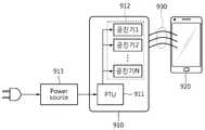
도 9는 N개의 공진기를 구비한 무선 전력 송신 장치를 통해서 커플링 영역을 검출하는 시스템을 나타낸 도면이다.9 is a diagram illustrating a system for detecting a coupling region through a wireless power transmission apparatus having N resonators.
도 9를 참조하면, 커플링 영역 검출 시스템은 무선 전력 송신 장치(910)와 무선 전력 수신 장치(920)로 구성될 수 있고, 무선 전력 송신 장치(910)는 N개의 공진기(912), PTU(911) 및 Power source(913)로 구성될 수 있다. Power source(913)는 무선 전력 송신 장치(910)의 내부 또는 외부에 위치할 수 있다. Power sourece(913)가 무선 전력 송신 장치(910)의 내부에 위치하는 경우, PTU(911)의 내부 또는 외부에 위치할 수 있다. N개의 공진기(912)는 물리적으로 이격되어 있으며, PTU(911)의 내부 또는 외부에 위치할 수 있다.Referring to FIG. 9, the coupling area detection system may include a wireless
N개의 공진기(912)는 각각 PTU(911)의 제어에 의해 무선 전력을 송신한다. 무선 전력 수신 장치(920)는 N개의 공진기(912)에 의해 송신된 전력을 수신하며, 무선 전력 송신 장치(910)와 무선 전력 수신 장치(920) 사이에 커플링(930)이 형성된다.Each of the
N개의 공진기(912)에 의해 송신되는 N개의 공진 전력의 특성에 따라 각각 특유의 커플링 영역이 형성될 수 있다. 이 때, 무선 전력 수신 장치(920)가 N개의 공진기(912)에 의해 형성된 각각의 커플링 영역 중 어느 곳에 위치하는지에 따라서 무선 전력 수신 장치(920)의 전력 수신율에 차이가 발생할 수 있다.A unique coupling region may be formed depending on the characteristics of the N resonant powers transmitted by the N resonators 912. At this time, a difference may occur in the power reception rate of the wireless
무선 전력 송신 장치(910)는 무선 전력 수신 장치(920)의 위치를 조정함으로써 전력 수신율을 증가시킬 수 있다. 무선 전력 송신 장치(910)는 도 8에서 설명된 810 내지 850 단계를 수행할 수 있고, 추가적으로, N개의 공진기를 스위칭하는 스위칭 회로(미도시)를 포함할 수 있다.The wireless
무선 전력 송신 장치(910)는 생성된 커플링 영역 업데이트 정보에 기초하여 N개의 공진기 중 무선 전력 수신 장치(920)와 가장 효율적인 커플링을 형성할 수 있는 공진기에 대한 정보를 획득할 수 있다. 또한, 무선 전력 송신 장치(910)는 무선 전력 수신 장치(920)와 가장 효율적인 커플링을 형성할 수 있는 공진기가 무선 전력 수신 장치(920)와 커플링(930)을 형성하도록 스위칭 회로(미도시)를 제어할 수 있다.The
일실시예로, N개의 공진기를 구비한 무선 전력 송신 장치와 복수개의 무선 전력 수신 장치가 있는 경우, 무선 전력 송신 장치는 각각의 무선 전력 수신 장치가 N개의 공진기 중 가장 효율적으로 전력을 수신할 수 있는 공진기와 커플링을 형성할 수 있도록 스위칭 회로를 제어할 수 있다. 또 다른 실시예로, 전기 자동차 충전스테이션에 N개의 공진기를 구비한 무선 전력 송신 장치가 설치되어 있는 경우, 전력을 공급받고자 하는 전기 자동차가 가장 근접한 위치의 공진기로부터 전력을 공급받을 수 있도록 스위칭 회로를 제어할 수 있다.
In one embodiment, when there are a plurality of wireless power receiving devices and a wireless power transmitting device having N resonators, each wireless power receiving device may receive power most efficiently among the N resonators. The switching circuit can be controlled to form a coupling with the resonator. In another embodiment, when a wireless power transmission device having N resonators is installed in an electric vehicle charging station, a switching circuit is provided so that the electric vehicle to be supplied with electric power is supplied with power from the resonator in the closest position. Can be controlled.
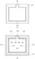
도 10은 공진기 패드를 이용해서 커플링 영역을 검출하는 시스템을 나타낸 도면이다.10 is a view showing a system for detecting a coupling region using a resonator pad.
도 10을 참조하면, 커플링 영역을 검출하는 시스템은 무선 전력 송신 장치(1010), 공진기 패드(1020) 및 무선 전력 수신 장치(1030)로 구성될 수 있다. 무선 전력 송신 장치(1010)는 공진기(1012), PTU(1011) 및 Power source(1013)로 구성될 수 있다. Power source(1013)는 무선 전력 송신 장치(1010)의 내부 또는 외부에 위치할 수 있다. Power sourece(1013)가 무선 전력 송신 장치(1010)의 내부에 위치하는 경우, PTU(1011)의 내부 또는 외부에 위치할 수 있다. 공진기(1012)는 PTU(1011)의 내부 또는 외부에 위치할 수 있다.Referring to FIG. 10, a system for detecting a coupling area may include a wireless
무선 전력 송신 장치(1010)에 의해 송신된 전력은 공진기 패드(1020)가 수신할 수 있고, 이 경우 무선 전력 송신 장치(1010)와 공진기 패드(1020) 간에 커플링(1040)이 형성될 수 있다. 공진기 패드(1020)는 무선 전력 송신 장치(1010)로부터 무선 전력을 수신하고, 수신된 전력을 이용하여 무선 전력 수신 장치(1040)에 무선 전력을 송신하는 트랜시버 역할을 할 수 있다. 공진기 패드(1020)는 무선 전력 송신 장치(1010)로 상태 정보를 전송할 수 있다. 상태 정보는 수신 전력, 임피던스, 수신 전압 또는 수신 전류 중 적어도 하나일 수 있다.
The power transmitted by the wireless
도 11은 공진기 패드의 이동에 따른 커플링 영역 검출 시스템을 나타낸 도면이다.11 is a view showing a coupling area detection system according to the movement of the resonator pad.
도 11을 참조하면, 커플링 영역 검출 시스템은 무선 전력 송신 장치(1110), 공진기 패드(1120) 및 무선 전력 수신 장치(1130)로 구성될 수 있다.Referring to FIG. 11, the coupling area detection system may include a wireless
공진기 패드(1120)는 수신 전력, 임피던스, 수신 전압 또는 수신 전류 중 적어도 하나에 대한 상태 정보를 무선 전력 송신 장치(1110)로 전송할 수 있다. 무선 전력 송신 장치(1110)는 공진기 패드(1120)로부터 수신한 상태 정보에 기초하여 공진기 패드(1120)가 최적의 커플링 영역에 위치하도록 유도할 수 있다. 공진기 패드(1120)는 최적의 커플링 영역에서 무선 전력을 효율적으로 수신할 수 있고, 수신한 무선 전력을 무선 전력 수신 장치(1130)로 송신할 수 있다. 커플링 영역 검출에 관한 상세한 내용은 도 1내지 도 10에서 설명되었으므로, 보다 상세한 설명은 생략한다.
The
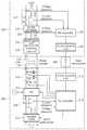
도 12는 무선 전력 송신 장치와 무선 전력 수신 장치를 나타낸 블록도이다.12 is a block diagram showing a wireless power transmitter and a wireless power receiver.
도 12를 참조하면, 무선 전력 송신 장치(1210)는 계산부(1211), 정보 생성부(1212), 처리부(1213) 및 통신부(1214)를 포함할 수 있다.Referring to FIG. 12, the wireless
통신부(1214)는 무선 전력 수신 장치의 상태 정보(1230)를 수신할 수 있다. 상태 정보(1230)는, 수신 전력, 임피던스, 수신 전압 또는 수신 전류 중 적어도 하나일 수 있다.The
계산부(1211)는 무선 전력 수신 장치(1220)의 움직임에 따른 상태 정보(1230)의 변화량을 계산할 수 있다.The
정보 생성부(1212)는 계산된 변화량에 기초하여 무선 전력 수신 장치(1220)의 커플링 영역 업데이트 정보(1240)를 생성할 수 있다.The
처리부(1213)는 통신부(1214), 계산부(1211) 및 정보 생성부(1212)의 동작이 반복하여 수행되도록 처리할 수 있다.The
무선 전력 송신 장치(1210)는 물리적으로 이격된 둘 이상의 공진기(미도시) 및 둘 이상의 공진기(미도시)를 스위칭하는 스위칭 회로(미도시)를 포함할 수 있고, 생성된 커플링 영역 업데이트 정보(1240)에 따라 스위칭 회로(미도시)를 제어하는 제어부(미도시)를 더 포함할 수 있다. 또한, 무선 전력 송신 장치(1210)는 생성된 커플링 영역 업데이트 정보(1240)를 외부로 출력하는 출력부(미도시)를 더 포함할 수 있다. 출력부(미도시)는, 커플링 영역 업데이트 정보(1240)를 시각적, 촉각적, 또는 청각적 방식 중 어느 하나의 방식으로 출력할 수 있다.The wireless
무선 전력 수신 장치(1220)는 통신부(1221) 및 출력부(1222)를 포함할 수 있다.The wireless
통신부(1221)는 무선 전력 송신 장치(1210)로 상태 정보(1230)를 전송하고, 무선 전력 송신 장치(1210)로부터 커플링 영역 업데이트 정보(1240)를 수신할 수 있다.The
출력부(1222)는 무선 전력 수신 장치(1220)는 커플링 영역 업데이트 정보를 시각적, 촉각적, 또는 청각적 방식 중 어느 하나의 방식으로 사용자에게 피드백할 수 있다.The
도 1 내지 11에서 설명된 내용은 도 12에 도시된 각각의 유닛에 그대로 적용될 수 있으므로, 보다 상세한 설명은 생략한다.
Since the contents described in FIGS. 1 to 11 can be applied to each unit shown in FIG. 12 as it is, a detailed description thereof will be omitted.
도 13은 예시적인 실시 예에 따른 부하 검출 원리를 설명하기 위한 도면이다.Fig. 13 is a diagram for explaining the principle of load detection according to an exemplary embodiment.
도 13를 참조하면, 부하 검출은 예를 들어 소스 공진기와 타겟 공진기 사이에서 수행될 수 있다. 공진 전력 전송에 있어서, 소스 공진기와 타겟 공진기 간의 임피던스를 고려한 전압 관계식은 [수학식 1]과 같이 정의될 수 있다.Referring to FIG. 13, load detection may be performed, for example, between a source resonator and a target resonator. In the transmission of the resonant power, the voltage relation equation considering the impedance between the source resonator and the target resonator may be defined as [Equation 1].
[수학식 1][Equation 1]

수학식 1에서, Vi는 소스측의 출력 전압, Vr은 임피던스 미스 매칭으로 인한반사 전압을 의미한다. 또한, 수학식 1에서 반사 계수
[수학식 2][Equation 2]

도 14는 무선 충전 패드가 내장된 무선 전력 송신 장치와 무선 전력 수신 장치를 나타낸 도면이다.14 is a view showing a wireless power transmitting apparatus and a wireless power receiving apparatus incorporating a wireless charging pad.
도 14를 참고하면, 노트북에 내장된 무선 충전 패드(1410) 위에 무선 전력 수신 장치(1420)가 놓여 있다. 무선 충전 패드(1410)는 화살표 방향으로 슬라이딩 될 수 있다. 무선 충전이 필요 없는 상황에서는 무선 충전 패드(1410)를 노트북 내부로 밀어 넣을 수 있고, 무선 충전이 필요한 상황에서는 무선 충전 패드(1410)를 노트북 외부로 노출시킬 수 있다.Referring to FIG. 14, a wireless
무선 충전 패드(1410)는 다양한 전자 장치와 결합될 수 있다. 예를 들면, 데스크탑, 노트북, 모니터, 키보드 등의 특정 부분에 무선 충전 패드(1410)가 결합될 수 있다. 또한, 전자 장치와 무선 충전 패드(1410)는 다양한 방식으로 결합 할 수 있다. 무선 충전 패드(1410)는 전자 장치에 슬라이딩 방식으로 결합되거나, 접이식, 탈착식, 고정식 등으로 결합될 수 있다. 무선 충전 패드(1410)가 전자 장치에 내장될 경우, 별도의 구매, 설치 과정이 필요 없으며, 공간을 효율적으로 활용할 수 있고, 디자인적 측면에서도 장점이 있다.
The
이상에서 설명된 장치는 하드웨어 구성요소, 소프트웨어 구성요소, 및/또는 하드웨어 구성요소 및 소프트웨어 구성요소의 조합으로 구현될 수 있다. 예를 들어, 실시예들에서 설명된 장치 및 구성요소는, 예를 들어, 프로세서, 콘트롤러, ALU(arithmetic logic unit), 디지털 신호 프로세서(digital signal processor), 마이크로컴퓨터, FPA(field programmable array), PLU(programmable logic unit), 마이크로프로세서, 또는 명령(instruction)을 실행하고 응답할 수 있는 다른 어떠한 장치와 같이, 하나 이상의 범용 컴퓨터 또는 특수 목적 컴퓨터를 이용하여 구현될 수 있다. 처리 장치는 운영 체제(OS) 및 상기 운영 체제 상에서 수행되는 하나 이상의 소프트웨어 애플리케이션을 수행할 수 있다. 또한, 처리 장치는 소프트웨어의 실행에 응답하여, 데이터를 접근, 저장, 조작, 처리 및 생성할 수도 있다. 이해의 편의를 위하여, 처리 장치는 하나가 사용되는 것으로 설명된 경우도 있지만, 해당 기술분야에서 통상의 지식을 가진 자는, 처리 장치가 복수 개의 처리 요소(processing element) 및/또는 복수 유형의 처리 요소를 포함할 수 있음을 알 수 있다. 예를 들어, 처리 장치는 복수 개의 프로세서 또는 하나의 프로세서 및 하나의 콘트롤러를 포함할 수 있다. 또한, 병렬 프로세서(parallel processor)와 같은, 다른 처리 구성(processing configuration)도 가능하다. The device described above may be implemented with hardware components, software components, and/or combinations of hardware components and software components. For example, the devices and components described in the embodiments include, for example, processors, controllers, arithmetic logic units (ALUs), digital signal processors (micro signal processors), microcomputers, field programmable arrays (FPAs), It may be implemented using one or more general purpose computers or special purpose computers, such as a programmable logic unit (PLU), microprocessor, or any other device capable of executing and responding to instructions. The processing device may run an operating system (OS) and one or more software applications running on the operating system. In addition, the processing device may access, store, manipulate, process, and generate data in response to execution of the software. For convenience of understanding, a processing device may be described as one being used, but a person having ordinary skill in the art, the processing device may include a plurality of processing elements and/or a plurality of types of processing elements. It can be seen that may include. For example, the processing device may include a plurality of processors or a processor and a controller. In addition, other processing configurations, such as parallel processors, are possible.
소프트웨어는 컴퓨터 프로그램(computer program), 코드(code), 명령(instruction), 또는 이들 중 하나 이상의 조합을 포함할 수 있으며, 원하는 대로 동작하도록 처리 장치를 구성하거나 독립적으로 또는 결합적으로(collectively) 처리 장치를 명령할 수 있다. 소프트웨어 및/또는 데이터는, 처리 장치에 의하여 해석되거나 처리 장치에 명령 또는 데이터를 제공하기 위하여, 어떤 유형의 기계, 구성요소(component), 물리적 장치, 가상 장치(virtual equipment), 컴퓨터 저장 매체 또는 장치, 또는 전송되는 신호 파(signal wave)에 영구적으로, 또는 일시적으로 구체화(embody)될 수 있다. 소프트웨어는 네트워크로 연결된 컴퓨터 시스템 상에 분산되어서, 분산된 방법으로 저장되거나 실행될 수도 있다. 소프트웨어 및 데이터는 하나 이상의 컴퓨터 판독 가능 기록 매체에 저장될 수 있다. The software may include a computer program, code, instruction, or a combination of one or more of these, and configure the processing device to operate as desired, or process independently or collectively You can command the device. Software and/or data may be interpreted by a processing device, or to provide instructions or data to a processing device, of any type of machine, component, physical device, virtual equipment, computer storage medium or device. , Or may be permanently or temporarily embodied in the transmitted signal wave. The software may be distributed over networked computer systems and stored or executed in a distributed manner. Software and data may be stored in one or more computer-readable recording media.
실시예에 따른 방법은 다양한 컴퓨터 수단을 통하여 수행될 수 있는 프로그램 명령 형태로 구현되어 컴퓨터 판독 가능 매체에 기록될 수 있다. 상기 컴퓨터 판독 가능 매체는 프로그램 명령, 데이터 파일, 데이터 구조 등을 단독으로 또는 조합하여 포함할 수 있다. 상기 매체에 기록되는 프로그램 명령은 실시예를 위하여 특별히 설계되고 구성된 것들이거나 컴퓨터 소프트웨어 당업자에게 공지되어 사용 가능한 것일 수도 있다. 컴퓨터 판독 가능 기록 매체의 예에는 하드 디스크, 플로피 디스크 및 자기 테이프와 같은 자기 매체(magnetic media), CD-ROM, DVD와 같은 광기록 매체(optical media), 플롭티컬 디스크(floptical disk)와 같은 자기-광 매체(magneto-optical media), 및 롬(ROM), 램(RAM), 플래시 메모리 등과 같은 프로그램 명령을 저장하고 수행하도록 특별히 구성된 하드웨어 장치가 포함된다. 프로그램 명령의 예에는 컴파일러에 의해 만들어지는 것과 같은 기계어 코드뿐만 아니라 인터프리터 등을 사용해서 컴퓨터에 의해서 실행될 수 있는 고급 언어 코드를 포함한다. 상기된 하드웨어 장치는 실시예의 동작을 수행하기 위해 하나 이상의 소프트웨어 모듈로서 작동하도록 구성될 수 있으며, 그 역도 마찬가지이다. The method according to the embodiment may be implemented in the form of program instructions that can be executed through various computer means and recorded on a computer-readable medium. The computer-readable medium may include program instructions, data files, data structures, or the like alone or in combination. The program instructions recorded in the medium may be specially designed and configured for the embodiments or may be known and usable by those skilled in computer software. Examples of computer-readable recording media include magnetic media such as hard disks, floppy disks, and magnetic tapes, optical media such as CD-ROMs, DVDs, and magnetic media such as floptical disks. -Hardware devices specifically configured to store and execute program instructions such as magneto-optical media, and ROM, RAM, flash memory, and the like. Examples of program instructions include high-level language code that can be executed by a computer using an interpreter, etc., as well as machine language codes produced by a compiler. The hardware device described above may be configured to operate as one or more software modules to perform the operations of the embodiments, and vice versa.
이상과 같이 실시예들이 비록 한정된 실시예와 도면에 의해 설명되었으나, 해당 기술분야에서 통상의 지식을 가진 자라면 상기의 기재로부터 다양한 수정 및 변형이 가능하다. 예를 들어, 설명된 기술들이 설명된 방법과 다른 순서로 수행되거나, 및/또는 설명된 시스템, 구조, 장치, 회로 등의 구성요소들이 설명된 방법과 다른 형태로 결합 또는 조합되거나, 다른 구성요소 또는 균등물에 의하여 대치되거나 치환되더라도 적절한 결과가 달성될 수 있다. As described above, although the embodiments have been described by a limited embodiment and drawings, those skilled in the art can make various modifications and variations from the above description. For example, the described techniques are performed in a different order than the described method, and/or the components of the described system, structure, device, circuit, etc. are combined or combined in a different form from the described method, or other components Alternatively, even if replaced or substituted by equivalents, appropriate results can be achieved.
그러므로, 다른 구현들, 다른 실시예들 및 특허청구범위와 균등한 것들도 후술하는 특허청구범위의 범위에 속한다.Therefore, other implementations, other embodiments, and equivalents to the claims are also within the scope of the following claims.
Claims (14)
Translated fromKorean무선 전력 수신 장치로부터 수신 전력, 임피던스, 수신 전압 및 수신 전류 중 적어도 하나를 포함하는 상태 정보를 수신하는 단계;
상기 상태 정보에 기초하여, 상기 무선 전력 송신 장치와 상기 무선 전력 수신 장치 간의 커플링 상태를 나타내는 커플링 영역 정보를 생성하는 단계;
사용자에 의한 상기 무선 전력 수신 장치의 위치 변화에 응답하여, 상기 커플링 영역 정보를 업데이트하는 단계; 및
상기 업데이트된 커플링 영역 정보에 대응하는 피드백을 출력하는 단계
를 포함하고,
상기 커플링 영역 정보는 상기 무선 전력 수신 장치의 상기 위치 변화에 기초하여 상기 무선 전력 수신 장치의 전력 수신율이 증가하였는지에 관한 정보를 포함하는,
무선 전력 송신 장치의 동작 방법.In the operation method of the wireless power transmission device,
Receiving state information including at least one of received power, impedance, received voltage, and received current from the wireless power receiving apparatus;
Generating coupling area information indicating a coupling state between the wireless power transmitter and the wireless power receiver based on the state information;
Updating the coupling area information in response to a position change of the wireless power receiving device by a user; And
Outputting feedback corresponding to the updated coupling region information
Including,
The coupling area information includes information on whether the power reception rate of the wireless power reception device has been increased based on the position change of the wireless power reception device,
Method of operation of a wireless power transmission device.
다른 무선 전력 송신 장치로부터 무선 전력을 수신하는 단계; 및
상기 수신된 무선 전력을 상기 무선 전력 수신 장치로 송신하는 단계
를 더 포함하는, 무선 전력 송신 장치의 동작 방법.According to claim 1,
Receiving wireless power from another wireless power transmission device; And
Transmitting the received wireless power to the wireless power receiving device
The method of operating a wireless power transmission apparatus further comprising a.
상기 피드백을 출력하는 단계는,
상기 피드백을 시각적, 촉각적, 및 청각적 방식 중 적어도 하나의 방식으로 출력하는 단계를 포함하는,
무선 전력 송신 장치의 동작 방법.The method of claim 1.
The step of outputting the feedback,
Outputting the feedback in at least one of a visual, tactile, and audible manner,
Method of operation of a wireless power transmission device.
상기 커플링 영역 정보를 상기 무선 전력 수신 장치로 전송하는 단계
를 더 포함하고,
상기 무선 전력 수신 장치는 상기 커플링 영역 정보를 시각적, 촉각적, 및 청각적 방식 중 적어도 하나의 방식으로 사용자에게 피드백하는,
무선 전력 송신 장치의 동작 방법.According to claim 1,
Transmitting the coupling area information to the wireless power receiving device
Further comprising,
The wireless power receiving device feedbacks the coupling area information to a user in at least one of visual, tactile, and audible methods,
Method of operation of a wireless power transmission device.
상기 무선 전력 송신 장치는 물리적으로 이격된 둘 이상의 공진기 및 상기 둘 이상의 공진기를 스위칭하는 스위칭 회로를 포함하고,
상기 생성된 커플링 영역 정보에 따라 상기 스위칭 회로를 제어하는 단계를 더 포함하는 무선 전력 송신 장치의 동작 방법.According to claim 1,
The wireless power transmission apparatus includes two or more resonators physically spaced apart and a switching circuit for switching the two or more resonators,
And controlling the switching circuit according to the generated coupling area information.
무선 전력 수신 장치로부터 수신 전력, 임피던스, 수신 전압 및 수신 전류 중 적어도 하나를 포함하는 상태 정보를 수신하는 통신부;
상기 상태 정보에 기초하여, 상기 무선 전력 송신 장치와 상기 무선 전력 수신 장치 간의 커플링 상태를 나타내는 커플링 영역 정보를 생성하고, 사용자에 의한 상기 무선 전력 수신 장치의 위치 변화에 응답하여, 상기 커플링 영역 정보를 업데이트하는 처리부; 및
상기 업데이트된 커플링 영역 정보에 대응하는 피드백을 출력하는 출력부
를 포함하고,
상기 커플링 영역 정보는 상기 무선 전력 수신 장치의 상기 위치 변화에 기초하여 상기 무선 전력 수신 장치의 전력 수신율이 증가하였는지에 관한 정보를 포함하는,
무선 전력 송신 장치.In the wireless power transmission device,
A communication unit that receives status information including at least one of received power, impedance, received voltage, and received current from the wireless power receiving apparatus;
Based on the state information, coupling area information indicating a coupling state between the wireless power transmitter and the wireless power receiver is generated, and in response to a change in the position of the wireless power receiver by the user, the coupling A processing unit for updating area information; And
An output unit that outputs feedback corresponding to the updated coupling region information
Including,
The coupling area information includes information on whether a power reception rate of the wireless power reception device has been increased based on the position change of the wireless power reception device,
Wireless power transmission device.
상기 무선 전력 송신 장치는 물리적으로 이격된 둘 이상의 공진기 및 상기 둘 이상의 공진기를 스위칭하는 스위칭 회로를 더 포함하고,
상기 생성된 커플링 영역 정보에 따라 상기 스위칭 회로를 제어하는 제어부를 더 포함하는 무선 전력 송신 장치.The method of claim 8,
The wireless power transmission apparatus further includes two or more resonators physically spaced apart and a switching circuit for switching the two or more resonators,
And a control unit controlling the switching circuit according to the generated coupling region information.
상기 출력부는,
상기 피드백을 시각적, 촉각적, 및 청각적 방식 중 적어도 하나의 방식으로 출력하는,
무선 전력 송신 장치.The method of claim 8.
The output unit,
Outputting the feedback in at least one of visual, tactile, and audible ways,
Wireless power transmission device.
무선 전력 송신 장치로 수신 전력, 임피던스, 수신 전압 및 수신 전류 중 적어도 하나를 포함하는 상태 정보를 전송하고, 상기 무선 전력 송신 장치로부터 커플링 영역 정보를 수신하는 통신부; 및
상기 커플링 영역 정보에 대응하는 피드백을 출력하는 출력부
를 포함하고,
상기 커플링 영역 정보는
상기 무선 전력 송신 장치와 상기 무선 전력 수신 장치 간의 커플링 상태를 나타내고,
상태 정보에 기초하여 생성되어, 사용자에 의한 상기 무선 전력 수신 장치의 위치 변화에 응답하여 업데이트되고,
상기 무선 전력 수신 장치의 상기 위치 변화에 기초하여 상기 무선 전력 수신 장치의 전력 수신율이 증가하였는지에 관한 정보를 포함하는,
무선 전력 수신 장치.In the wireless power receiving device,
A communication unit that transmits status information including at least one of received power, impedance, received voltage, and received current to the wireless power transmitting apparatus, and receives coupling area information from the wireless power transmitting apparatus; And
An output unit that outputs feedback corresponding to the coupling region information
Including,
The coupling area information
Represents a coupling state between the wireless power transmitter and the wireless power receiver,
It is generated based on the status information, updated in response to a change in the position of the wireless power receiving device by the user,
Including information on whether the power reception rate of the wireless power reception device has increased based on the position change of the wireless power reception device,
Wireless power receiving device.
Priority Applications (5)
| Application Number | Priority Date | Filing Date | Title |
|---|---|---|---|
| KR1020130084194AKR102113853B1 (en) | 2013-07-17 | 2013-07-17 | Method and aparatus of detecting coupling region |
| US14/320,813US20150022012A1 (en) | 2013-07-17 | 2014-07-01 | Method and apparatus for detecting coupling region |
| PCT/KR2014/006411WO2015009042A1 (en) | 2013-07-17 | 2014-07-16 | Method and apparatus for detecting coupling region |
| EP14826106.8AEP3000164B1 (en) | 2013-07-17 | 2014-07-16 | Method and apparatus for detecting coupling region |
| CN201480040410.7ACN105379066A (en) | 2013-07-17 | 2014-07-16 | Method and apparatus for detecting coupling region |
Applications Claiming Priority (1)
| Application Number | Priority Date | Filing Date | Title |
|---|---|---|---|
| KR1020130084194AKR102113853B1 (en) | 2013-07-17 | 2013-07-17 | Method and aparatus of detecting coupling region |
Publications (2)
| Publication Number | Publication Date |
|---|---|
| KR20150010029A KR20150010029A (en) | 2015-01-28 |
| KR102113853B1true KR102113853B1 (en) | 2020-06-03 |
Family
ID=52343025
Family Applications (1)
| Application Number | Title | Priority Date | Filing Date |
|---|---|---|---|
| KR1020130084194AActiveKR102113853B1 (en) | 2013-07-17 | 2013-07-17 | Method and aparatus of detecting coupling region |
Country Status (5)
| Country | Link |
|---|---|
| US (1) | US20150022012A1 (en) |
| EP (1) | EP3000164B1 (en) |
| KR (1) | KR102113853B1 (en) |
| CN (1) | CN105379066A (en) |
| WO (1) | WO2015009042A1 (en) |
Families Citing this family (176)
| Publication number | Priority date | Publication date | Assignee | Title |
|---|---|---|---|---|
| US9060770B2 (en) | 2003-05-20 | 2015-06-23 | Ethicon Endo-Surgery, Inc. | Robotically-driven surgical instrument with E-beam driver |
| US20070084897A1 (en) | 2003-05-20 | 2007-04-19 | Shelton Frederick E Iv | Articulating surgical stapling instrument incorporating a two-piece e-beam firing mechanism |
| US11890012B2 (en) | 2004-07-28 | 2024-02-06 | Cilag Gmbh International | Staple cartridge comprising cartridge body and attached support |
| US9072535B2 (en) | 2011-05-27 | 2015-07-07 | Ethicon Endo-Surgery, Inc. | Surgical stapling instruments with rotatable staple deployment arrangements |
| US11998198B2 (en) | 2004-07-28 | 2024-06-04 | Cilag Gmbh International | Surgical stapling instrument incorporating a two-piece E-beam firing mechanism |
| US11246590B2 (en) | 2005-08-31 | 2022-02-15 | Cilag Gmbh International | Staple cartridge including staple drivers having different unfired heights |
| US7669746B2 (en) | 2005-08-31 | 2010-03-02 | Ethicon Endo-Surgery, Inc. | Staple cartridges for forming staples having differing formed staple heights |
| US10159482B2 (en) | 2005-08-31 | 2018-12-25 | Ethicon Llc | Fastener cartridge assembly comprising a fixed anvil and different staple heights |
| US7845537B2 (en) | 2006-01-31 | 2010-12-07 | Ethicon Endo-Surgery, Inc. | Surgical instrument having recording capabilities |
| US20120292367A1 (en) | 2006-01-31 | 2012-11-22 | Ethicon Endo-Surgery, Inc. | Robotically-controlled end effector |
| US8708213B2 (en) | 2006-01-31 | 2014-04-29 | Ethicon Endo-Surgery, Inc. | Surgical instrument having a feedback system |
| US8186555B2 (en) | 2006-01-31 | 2012-05-29 | Ethicon Endo-Surgery, Inc. | Motor-driven surgical cutting and fastening instrument with mechanical closure system |
| US11793518B2 (en) | 2006-01-31 | 2023-10-24 | Cilag Gmbh International | Powered surgical instruments with firing system lockout arrangements |
| US8992422B2 (en) | 2006-03-23 | 2015-03-31 | Ethicon Endo-Surgery, Inc. | Robotically-controlled endoscopic accessory channel |
| US11980366B2 (en) | 2006-10-03 | 2024-05-14 | Cilag Gmbh International | Surgical instrument |
| US8632535B2 (en) | 2007-01-10 | 2014-01-21 | Ethicon Endo-Surgery, Inc. | Interlock and surgical instrument including same |
| US8684253B2 (en) | 2007-01-10 | 2014-04-01 | Ethicon Endo-Surgery, Inc. | Surgical instrument with wireless communication between a control unit of a robotic system and remote sensor |
| US20080169333A1 (en) | 2007-01-11 | 2008-07-17 | Shelton Frederick E | Surgical stapler end effector with tapered distal end |
| US11564682B2 (en) | 2007-06-04 | 2023-01-31 | Cilag Gmbh International | Surgical stapler device |
| US8931682B2 (en) | 2007-06-04 | 2015-01-13 | Ethicon Endo-Surgery, Inc. | Robotically-controlled shaft based rotary drive systems for surgical instruments |
| US11849941B2 (en) | 2007-06-29 | 2023-12-26 | Cilag Gmbh International | Staple cartridge having staple cavities extending at a transverse angle relative to a longitudinal cartridge axis |
| US8573465B2 (en) | 2008-02-14 | 2013-11-05 | Ethicon Endo-Surgery, Inc. | Robotically-controlled surgical end effector system with rotary actuated closure systems |
| JP5410110B2 (en) | 2008-02-14 | 2014-02-05 | エシコン・エンド−サージェリィ・インコーポレイテッド | Surgical cutting / fixing instrument with RF electrode |
| US8636736B2 (en) | 2008-02-14 | 2014-01-28 | Ethicon Endo-Surgery, Inc. | Motorized surgical cutting and fastening instrument |
| US11986183B2 (en) | 2008-02-14 | 2024-05-21 | Cilag Gmbh International | Surgical cutting and fastening instrument comprising a plurality of sensors to measure an electrical parameter |
| US9585657B2 (en) | 2008-02-15 | 2017-03-07 | Ethicon Endo-Surgery, Llc | Actuator for releasing a layer of material from a surgical end effector |
| US9005230B2 (en) | 2008-09-23 | 2015-04-14 | Ethicon Endo-Surgery, Inc. | Motorized surgical instrument |
| US8210411B2 (en) | 2008-09-23 | 2012-07-03 | Ethicon Endo-Surgery, Inc. | Motor-driven surgical cutting instrument |
| US9386983B2 (en) | 2008-09-23 | 2016-07-12 | Ethicon Endo-Surgery, Llc | Robotically-controlled motorized surgical instrument |
| US8608045B2 (en) | 2008-10-10 | 2013-12-17 | Ethicon Endo-Sugery, Inc. | Powered surgical cutting and stapling apparatus with manually retractable firing system |
| US9629814B2 (en) | 2010-09-30 | 2017-04-25 | Ethicon Endo-Surgery, Llc | Tissue thickness compensator configured to redistribute compressive forces |
| US12213666B2 (en) | 2010-09-30 | 2025-02-04 | Cilag Gmbh International | Tissue thickness compensator comprising layers |
| US10945731B2 (en) | 2010-09-30 | 2021-03-16 | Ethicon Llc | Tissue thickness compensator comprising controlled release and expansion |
| US11812965B2 (en) | 2010-09-30 | 2023-11-14 | Cilag Gmbh International | Layer of material for a surgical end effector |
| US9788834B2 (en) | 2010-09-30 | 2017-10-17 | Ethicon Llc | Layer comprising deployable attachment members |
| US9386988B2 (en) | 2010-09-30 | 2016-07-12 | Ethicon End-Surgery, LLC | Retainer assembly including a tissue thickness compensator |
| US11925354B2 (en) | 2010-09-30 | 2024-03-12 | Cilag Gmbh International | Staple cartridge comprising staples positioned within a compressible portion thereof |
| AU2012250197B2 (en) | 2011-04-29 | 2017-08-10 | Ethicon Endo-Surgery, Inc. | Staple cartridge comprising staples positioned within a compressible portion thereof |
| US11207064B2 (en) | 2011-05-27 | 2021-12-28 | Cilag Gmbh International | Automated end effector component reloading system for use with a robotic system |
| BR112014024098B1 (en) | 2012-03-28 | 2021-05-25 | Ethicon Endo-Surgery, Inc. | staple cartridge |
| MX358135B (en) | 2012-03-28 | 2018-08-06 | Ethicon Endo Surgery Inc | Tissue thickness compensator comprising a plurality of layers. |
| US9101358B2 (en) | 2012-06-15 | 2015-08-11 | Ethicon Endo-Surgery, Inc. | Articulatable surgical instrument comprising a firing drive |
| US20140001231A1 (en) | 2012-06-28 | 2014-01-02 | Ethicon Endo-Surgery, Inc. | Firing system lockout arrangements for surgical instruments |
| US12383267B2 (en) | 2012-06-28 | 2025-08-12 | Cilag Gmbh International | Robotically powered surgical device with manually-actuatable reversing system |
| US9289256B2 (en) | 2012-06-28 | 2016-03-22 | Ethicon Endo-Surgery, Llc | Surgical end effectors having angled tissue-contacting surfaces |
| KR102028112B1 (en)* | 2013-01-14 | 2019-10-04 | 삼성전자주식회사 | Apparatus for power and data transmission and data reception using mutual resonance, apparatus for power and data reception and data transmission using mutual resonance, method thereof |
| BR112015021082B1 (en) | 2013-03-01 | 2022-05-10 | Ethicon Endo-Surgery, Inc | surgical instrument |
| RU2672520C2 (en) | 2013-03-01 | 2018-11-15 | Этикон Эндо-Серджери, Инк. | Hingedly turnable surgical instruments with conducting ways for signal transfer |
| US9629629B2 (en) | 2013-03-14 | 2017-04-25 | Ethicon Endo-Surgey, LLC | Control systems for surgical instruments |
| BR112015026109B1 (en) | 2013-04-16 | 2022-02-22 | Ethicon Endo-Surgery, Inc | surgical instrument |
| US9775609B2 (en) | 2013-08-23 | 2017-10-03 | Ethicon Llc | Tamper proof circuit for surgical instrument battery pack |
| US20150272580A1 (en) | 2014-03-26 | 2015-10-01 | Ethicon Endo-Surgery, Inc. | Verification of number of battery exchanges/procedure count |
| US10013049B2 (en) | 2014-03-26 | 2018-07-03 | Ethicon Llc | Power management through sleep options of segmented circuit and wake up control |
| US12232723B2 (en) | 2014-03-26 | 2025-02-25 | Cilag Gmbh International | Systems and methods for controlling a segmented circuit |
| US10327764B2 (en) | 2014-09-26 | 2019-06-25 | Ethicon Llc | Method for creating a flexible staple line |
| BR112016023825B1 (en) | 2014-04-16 | 2022-08-02 | Ethicon Endo-Surgery, Llc | STAPLE CARTRIDGE FOR USE WITH A SURGICAL STAPLER AND STAPLE CARTRIDGE FOR USE WITH A SURGICAL INSTRUMENT |
| CN106456159B (en) | 2014-04-16 | 2019-03-08 | 伊西康内外科有限责任公司 | Fastener Cartridge Assembly and Nail Retainer Cover Arrangement |
| CN106456176B (en) | 2014-04-16 | 2019-06-28 | 伊西康内外科有限责任公司 | Fastener Cartridge Including Extensions With Different Configurations |
| US20150297225A1 (en) | 2014-04-16 | 2015-10-22 | Ethicon Endo-Surgery, Inc. | Fastener cartridges including extensions having different configurations |
| US11311294B2 (en) | 2014-09-05 | 2022-04-26 | Cilag Gmbh International | Powered medical device including measurement of closure state of jaws |
| BR112017004361B1 (en) | 2014-09-05 | 2023-04-11 | Ethicon Llc | ELECTRONIC SYSTEM FOR A SURGICAL INSTRUMENT |
| US10105142B2 (en) | 2014-09-18 | 2018-10-23 | Ethicon Llc | Surgical stapler with plurality of cutting elements |
| US11523821B2 (en) | 2014-09-26 | 2022-12-13 | Cilag Gmbh International | Method for creating a flexible staple line |
| US9924944B2 (en) | 2014-10-16 | 2018-03-27 | Ethicon Llc | Staple cartridge comprising an adjunct material |
| US10517594B2 (en) | 2014-10-29 | 2019-12-31 | Ethicon Llc | Cartridge assemblies for surgical staplers |
| US10736636B2 (en) | 2014-12-10 | 2020-08-11 | Ethicon Llc | Articulatable surgical instrument system |
| US10085748B2 (en) | 2014-12-18 | 2018-10-02 | Ethicon Llc | Locking arrangements for detachable shaft assemblies with articulatable surgical end effectors |
| US9987000B2 (en) | 2014-12-18 | 2018-06-05 | Ethicon Llc | Surgical instrument assembly comprising a flexible articulation system |
| US9483097B2 (en)* | 2015-01-16 | 2016-11-01 | Diwin Technology Co., Ltd. | Power-free wireless operation device of portable electronic device |
| US20160211064A1 (en)* | 2015-01-19 | 2016-07-21 | Industry-Academic Cooperation Foundation Chosun University | Wireless power charging apparatus using superconducting coil |
| US11154301B2 (en) | 2015-02-27 | 2021-10-26 | Cilag Gmbh International | Modular stapling assembly |
| WO2016137295A1 (en)* | 2015-02-27 | 2016-09-01 | Samsung Electronics Co., Ltd. | Electronic device and application control method thereof |
| US10441279B2 (en) | 2015-03-06 | 2019-10-15 | Ethicon Llc | Multiple level thresholds to modify operation of powered surgical instruments |
| US10433844B2 (en) | 2015-03-31 | 2019-10-08 | Ethicon Llc | Surgical instrument with selectively disengageable threaded drive systems |
| CN106208172B (en)* | 2015-04-30 | 2020-06-16 | 微软技术许可有限责任公司 | Wireless charging, communication and authentication technology for mobile client equipment |
| US10105139B2 (en) | 2015-09-23 | 2018-10-23 | Ethicon Llc | Surgical stapler having downstream current-based motor control |
| US10299878B2 (en) | 2015-09-25 | 2019-05-28 | Ethicon Llc | Implantable adjunct systems for determining adjunct skew |
| US10478188B2 (en) | 2015-09-30 | 2019-11-19 | Ethicon Llc | Implantable layer comprising a constricted configuration |
| US11890015B2 (en) | 2015-09-30 | 2024-02-06 | Cilag Gmbh International | Compressible adjunct with crossing spacer fibers |
| US10433846B2 (en) | 2015-09-30 | 2019-10-08 | Ethicon Llc | Compressible adjunct with crossing spacer fibers |
| US10292704B2 (en) | 2015-12-30 | 2019-05-21 | Ethicon Llc | Mechanisms for compensating for battery pack failure in powered surgical instruments |
| US10265068B2 (en) | 2015-12-30 | 2019-04-23 | Ethicon Llc | Surgical instruments with separable motors and motor control circuits |
| US11213293B2 (en) | 2016-02-09 | 2022-01-04 | Cilag Gmbh International | Articulatable surgical instruments with single articulation link arrangements |
| US10448948B2 (en) | 2016-02-12 | 2019-10-22 | Ethicon Llc | Mechanisms for compensating for drivetrain failure in powered surgical instruments |
| JP2017184563A (en)* | 2016-03-31 | 2017-10-05 | 古河電気工業株式会社 | Power transmission and reception system and power transmission apparatus |
| US10357247B2 (en) | 2016-04-15 | 2019-07-23 | Ethicon Llc | Surgical instrument with multiple program responses during a firing motion |
| US10828028B2 (en) | 2016-04-15 | 2020-11-10 | Ethicon Llc | Surgical instrument with multiple program responses during a firing motion |
| US20170296173A1 (en) | 2016-04-18 | 2017-10-19 | Ethicon Endo-Surgery, Llc | Method for operating a surgical instrument |
| US10500000B2 (en) | 2016-08-16 | 2019-12-10 | Ethicon Llc | Surgical tool with manual control of end effector jaws |
| US10813638B2 (en) | 2016-12-21 | 2020-10-27 | Ethicon Llc | Surgical end effectors with expandable tissue stop arrangements |
| JP7010957B2 (en) | 2016-12-21 | 2022-01-26 | エシコン エルエルシー | Shaft assembly with lockout |
| US20180168625A1 (en) | 2016-12-21 | 2018-06-21 | Ethicon Endo-Surgery, Llc | Surgical stapling instruments with smart staple cartridges |
| JP7010956B2 (en) | 2016-12-21 | 2022-01-26 | エシコン エルエルシー | How to staple tissue |
| US10973516B2 (en) | 2016-12-21 | 2021-04-13 | Ethicon Llc | Surgical end effectors and adaptable firing members therefor |
| US11090048B2 (en) | 2016-12-21 | 2021-08-17 | Cilag Gmbh International | Method for resetting a fuse of a surgical instrument shaft |
| US10779820B2 (en) | 2017-06-20 | 2020-09-22 | Ethicon Llc | Systems and methods for controlling motor speed according to user input for a surgical instrument |
| US10307170B2 (en) | 2017-06-20 | 2019-06-04 | Ethicon Llc | Method for closed loop control of motor velocity of a surgical stapling and cutting instrument |
| US11484310B2 (en) | 2017-06-28 | 2022-11-01 | Cilag Gmbh International | Surgical instrument comprising a shaft including a closure tube profile |
| USD906355S1 (en) | 2017-06-28 | 2020-12-29 | Ethicon Llc | Display screen or portion thereof with a graphical user interface for a surgical instrument |
| EP3420947B1 (en) | 2017-06-28 | 2022-05-25 | Cilag GmbH International | Surgical instrument comprising selectively actuatable rotatable couplers |
| US10932772B2 (en) | 2017-06-29 | 2021-03-02 | Ethicon Llc | Methods for closed loop velocity control for robotic surgical instrument |
| US11974742B2 (en) | 2017-08-03 | 2024-05-07 | Cilag Gmbh International | Surgical system comprising an articulation bailout |
| US11944300B2 (en) | 2017-08-03 | 2024-04-02 | Cilag Gmbh International | Method for operating a surgical system bailout |
| US11134944B2 (en) | 2017-10-30 | 2021-10-05 | Cilag Gmbh International | Surgical stapler knife motion controls |
| US10842490B2 (en) | 2017-10-31 | 2020-11-24 | Ethicon Llc | Cartridge body design with force reduction based on firing completion |
| US10779826B2 (en) | 2017-12-15 | 2020-09-22 | Ethicon Llc | Methods of operating surgical end effectors |
| US10835330B2 (en) | 2017-12-19 | 2020-11-17 | Ethicon Llc | Method for determining the position of a rotatable jaw of a surgical instrument attachment assembly |
| US11179151B2 (en) | 2017-12-21 | 2021-11-23 | Cilag Gmbh International | Surgical instrument comprising a display |
| US12336705B2 (en) | 2017-12-21 | 2025-06-24 | Cilag Gmbh International | Continuous use self-propelled stapling instrument |
| EP3763017A1 (en) | 2018-03-07 | 2021-01-13 | Telefonaktiebolaget LM Ericsson (publ) | Technique for wirelessly charging a wireless device in a wireless communication system |
| JP6977654B2 (en)* | 2018-03-30 | 2021-12-08 | Tdk株式会社 | Wireless power receiving device and wireless power transmission system |
| WO2019204377A1 (en)* | 2018-04-19 | 2019-10-24 | General Electric Company | System and method for determining an alignment of an apparatus coil |
| CN120320516A (en) | 2018-04-19 | 2025-07-15 | 通用电气公司 | Device, system and method for detecting foreign matter |
| US11291440B2 (en) | 2018-08-20 | 2022-04-05 | Cilag Gmbh International | Method for operating a powered articulatable surgical instrument |
| US20200054321A1 (en) | 2018-08-20 | 2020-02-20 | Ethicon Llc | Surgical instruments with progressive jaw closure arrangements |
| US11207065B2 (en) | 2018-08-20 | 2021-12-28 | Cilag Gmbh International | Method for fabricating surgical stapler anvils |
| KR102134863B1 (en)* | 2018-12-31 | 2020-07-17 | 한밭대학교 산학협력단 | Wireless power transmission system including a plurality of transmission coils and control method thereof |
| US11696761B2 (en) | 2019-03-25 | 2023-07-11 | Cilag Gmbh International | Firing drive arrangements for surgical systems |
| US20200345359A1 (en) | 2019-04-30 | 2020-11-05 | Ethicon Llc | Tissue stop for a surgical instrument |
| US11903581B2 (en) | 2019-04-30 | 2024-02-20 | Cilag Gmbh International | Methods for stapling tissue using a surgical instrument |
| US11241235B2 (en) | 2019-06-28 | 2022-02-08 | Cilag Gmbh International | Method of using multiple RFID chips with a surgical assembly |
| US11771419B2 (en) | 2019-06-28 | 2023-10-03 | Cilag Gmbh International | Packaging for a replaceable component of a surgical stapling system |
| US11684434B2 (en) | 2019-06-28 | 2023-06-27 | Cilag Gmbh International | Surgical RFID assemblies for instrument operational setting control |
| US12035913B2 (en) | 2019-12-19 | 2024-07-16 | Cilag Gmbh International | Staple cartridge comprising a deployable knife |
| US11701111B2 (en) | 2019-12-19 | 2023-07-18 | Cilag Gmbh International | Method for operating a surgical stapling instrument |
| EP4091234A4 (en)* | 2020-01-14 | 2024-04-17 | Etherdyne Technologies, Inc. | Resonant wireless power source having coupled resonators oscillating in a single resonant eigenmode |
| US11871925B2 (en) | 2020-07-28 | 2024-01-16 | Cilag Gmbh International | Surgical instruments with dual spherical articulation joint arrangements |
| US12053175B2 (en) | 2020-10-29 | 2024-08-06 | Cilag Gmbh International | Surgical instrument comprising a stowed closure actuator stop |
| US11931025B2 (en) | 2020-10-29 | 2024-03-19 | Cilag Gmbh International | Surgical instrument comprising a releasable closure drive lock |
| USD1013170S1 (en) | 2020-10-29 | 2024-01-30 | Cilag Gmbh International | Surgical instrument assembly |
| US11896217B2 (en) | 2020-10-29 | 2024-02-13 | Cilag Gmbh International | Surgical instrument comprising an articulation lock |
| US11779330B2 (en) | 2020-10-29 | 2023-10-10 | Cilag Gmbh International | Surgical instrument comprising a jaw alignment system |
| US11890010B2 (en) | 2020-12-02 | 2024-02-06 | Cllag GmbH International | Dual-sided reinforced reload for surgical instruments |
| US11744581B2 (en) | 2020-12-02 | 2023-09-05 | Cilag Gmbh International | Powered surgical instruments with multi-phase tissue treatment |
| US11737751B2 (en) | 2020-12-02 | 2023-08-29 | Cilag Gmbh International | Devices and methods of managing energy dissipated within sterile barriers of surgical instrument housings |
| US11849943B2 (en) | 2020-12-02 | 2023-12-26 | Cilag Gmbh International | Surgical instrument with cartridge release mechanisms |
| US11944296B2 (en) | 2020-12-02 | 2024-04-02 | Cilag Gmbh International | Powered surgical instruments with external connectors |
| US12399295B2 (en) | 2021-02-16 | 2025-08-26 | Ge Intellectual Property Licensing, Llc | Foreign object detection in a wireless power transfer system |
| US12298461B2 (en) | 2021-02-16 | 2025-05-13 | Ge Intellectual Property Licensing, Llc | Foreign object detection in a wireless power transfer system |
| US11812964B2 (en) | 2021-02-26 | 2023-11-14 | Cilag Gmbh International | Staple cartridge comprising a power management circuit |
| US11950777B2 (en) | 2021-02-26 | 2024-04-09 | Cilag Gmbh International | Staple cartridge comprising an information access control system |
| US11696757B2 (en) | 2021-02-26 | 2023-07-11 | Cilag Gmbh International | Monitoring of internal systems to detect and track cartridge motion status |
| US11723657B2 (en) | 2021-02-26 | 2023-08-15 | Cilag Gmbh International | Adjustable communication based on available bandwidth and power capacity |
| US11701113B2 (en) | 2021-02-26 | 2023-07-18 | Cilag Gmbh International | Stapling instrument comprising a separate power antenna and a data transfer antenna |
| US12324580B2 (en) | 2021-02-26 | 2025-06-10 | Cilag Gmbh International | Method of powering and communicating with a staple cartridge |
| US12108951B2 (en) | 2021-02-26 | 2024-10-08 | Cilag Gmbh International | Staple cartridge comprising a sensing array and a temperature control system |
| US11744583B2 (en)* | 2021-02-26 | 2023-09-05 | Cilag Gmbh International | Distal communication array to tune frequency of RF systems |
| US11730473B2 (en) | 2021-02-26 | 2023-08-22 | Cilag Gmbh International | Monitoring of manufacturing life-cycle |
| US11751869B2 (en) | 2021-02-26 | 2023-09-12 | Cilag Gmbh International | Monitoring of multiple sensors over time to detect moving characteristics of tissue |
| US11980362B2 (en) | 2021-02-26 | 2024-05-14 | Cilag Gmbh International | Surgical instrument system comprising a power transfer coil |
| US11749877B2 (en) | 2021-02-26 | 2023-09-05 | Cilag Gmbh International | Stapling instrument comprising a signal antenna |
| US11793514B2 (en) | 2021-02-26 | 2023-10-24 | Cilag Gmbh International | Staple cartridge comprising sensor array which may be embedded in cartridge body |
| US11717291B2 (en) | 2021-03-22 | 2023-08-08 | Cilag Gmbh International | Staple cartridge comprising staples configured to apply different tissue compression |
| US11826042B2 (en) | 2021-03-22 | 2023-11-28 | Cilag Gmbh International | Surgical instrument comprising a firing drive including a selectable leverage mechanism |
| US11737749B2 (en) | 2021-03-22 | 2023-08-29 | Cilag Gmbh International | Surgical stapling instrument comprising a retraction system |
| US11806011B2 (en) | 2021-03-22 | 2023-11-07 | Cilag Gmbh International | Stapling instrument comprising tissue compression systems |
| US11826012B2 (en) | 2021-03-22 | 2023-11-28 | Cilag Gmbh International | Stapling instrument comprising a pulsed motor-driven firing rack |
| US11759202B2 (en) | 2021-03-22 | 2023-09-19 | Cilag Gmbh International | Staple cartridge comprising an implantable layer |
| US11723658B2 (en) | 2021-03-22 | 2023-08-15 | Cilag Gmbh International | Staple cartridge comprising a firing lockout |
| US11786243B2 (en) | 2021-03-24 | 2023-10-17 | Cilag Gmbh International | Firing members having flexible portions for adapting to a load during a surgical firing stroke |
| US11744603B2 (en) | 2021-03-24 | 2023-09-05 | Cilag Gmbh International | Multi-axis pivot joints for surgical instruments and methods for manufacturing same |
| US11896218B2 (en) | 2021-03-24 | 2024-02-13 | Cilag Gmbh International | Method of using a powered stapling device |
| US11849945B2 (en) | 2021-03-24 | 2023-12-26 | Cilag Gmbh International | Rotary-driven surgical stapling assembly comprising eccentrically driven firing member |
| US11793516B2 (en) | 2021-03-24 | 2023-10-24 | Cilag Gmbh International | Surgical staple cartridge comprising longitudinal support beam |
| US11786239B2 (en) | 2021-03-24 | 2023-10-17 | Cilag Gmbh International | Surgical instrument articulation joint arrangements comprising multiple moving linkage features |
| US11832816B2 (en) | 2021-03-24 | 2023-12-05 | Cilag Gmbh International | Surgical stapling assembly comprising nonplanar staples and planar staples |
| US11896219B2 (en) | 2021-03-24 | 2024-02-13 | Cilag Gmbh International | Mating features between drivers and underside of a cartridge deck |
| US11849944B2 (en) | 2021-03-24 | 2023-12-26 | Cilag Gmbh International | Drivers for fastener cartridge assemblies having rotary drive screws |
| US11903582B2 (en) | 2021-03-24 | 2024-02-20 | Cilag Gmbh International | Leveraging surfaces for cartridge installation |
| US12102323B2 (en) | 2021-03-24 | 2024-10-01 | Cilag Gmbh International | Rotary-driven surgical stapling assembly comprising a floatable component |
| US11857183B2 (en) | 2021-03-24 | 2024-01-02 | Cilag Gmbh International | Stapling assembly components having metal substrates and plastic bodies |
| US11826047B2 (en) | 2021-05-28 | 2023-11-28 | Cilag Gmbh International | Stapling instrument comprising jaw mounts |
| US11980363B2 (en) | 2021-10-18 | 2024-05-14 | Cilag Gmbh International | Row-to-row staple array variations |
| US12432790B2 (en) | 2021-10-28 | 2025-09-30 | Cilag Gmbh International | Method and device for transmitting UART communications over a security short range wireless communication |
| US11937816B2 (en) | 2021-10-28 | 2024-03-26 | Cilag Gmbh International | Electrical lead arrangements for surgical instruments |
| US12089841B2 (en) | 2021-10-28 | 2024-09-17 | Cilag CmbH International | Staple cartridge identification systems |
Citations (2)
| Publication number | Priority date | Publication date | Assignee | Title |
|---|---|---|---|---|
| WO2003105308A1 (en)* | 2002-01-11 | 2003-12-18 | City University Of Hong Kong | Planar inductive battery charger |
| WO2012102302A1 (en) | 2011-01-25 | 2012-08-02 | 株式会社明電舎 | Contactless power feeding apparatus and contactless power feeding method |
Family Cites Families (36)
| Publication number | Priority date | Publication date | Assignee | Title |
|---|---|---|---|---|
| JP4462614B2 (en)* | 2004-07-05 | 2010-05-12 | ソニー・エリクソン・モバイルコミュニケーションズ株式会社 | Short-range wireless communication system, portable terminal device, and wireless communication device |
| US7443057B2 (en)* | 2004-11-29 | 2008-10-28 | Patrick Nunally | Remote power charging of electronic devices |
| KR20110103408A (en)* | 2009-01-08 | 2011-09-20 | 엔이씨 도낀 가부시끼가이샤 | Power transmission device and non-contact power transmission system |
| US8775846B2 (en)* | 2009-07-10 | 2014-07-08 | Protonex Technology Corporation | Portable power manager having one or more device ports for connecting with external power loads |
| JP2011160505A (en)* | 2010-01-29 | 2011-08-18 | Sony Corp | Wireless charging apparatus and wireless charging system |
| KR101697364B1 (en)* | 2010-02-17 | 2017-01-17 | 삼성전자주식회사 | Apparatus for transmitting/receving wireless power having resonance frequency stabilization circuit |
| KR101672736B1 (en)* | 2010-05-14 | 2016-11-04 | 삼성전자주식회사 | Apparatus and method for power and data transmission using mobile device |
| JP5539069B2 (en)* | 2010-06-30 | 2014-07-02 | キヤノン株式会社 | Power supply device |
| JP5539068B2 (en)* | 2010-06-30 | 2014-07-02 | キヤノン株式会社 | Power supply device |
| CN101860090A (en)* | 2010-07-01 | 2010-10-13 | 王干 | Highway-based solar photovoltaic wireless power supply system |
| KR20120005112A (en)* | 2010-07-08 | 2012-01-16 | 삼성전자주식회사 | Adaptive Wireless Power Transmission Apparatus and Method for Mobile Vehicle in Wireless Power Transmission System |
| JP5659704B2 (en)* | 2010-08-30 | 2015-01-28 | ソニー株式会社 | Contactless power supply system |
| CN102570128A (en)* | 2010-12-11 | 2012-07-11 | 张志平 | Power socket with wireless induction charging module |
| US9199545B2 (en)* | 2011-06-01 | 2015-12-01 | Samsung Electronics Co., Ltd. | Method and apparatus for controlling wireless power transmission |
| KR101810465B1 (en)* | 2011-06-10 | 2018-01-25 | 엘지전자 주식회사 | Apparatus for Handling of Orientation Changing of Terminal during Wireless Power Transfer and Method Thereof |
| US9252846B2 (en)* | 2011-09-09 | 2016-02-02 | Qualcomm Incorporated | Systems and methods for detecting and identifying a wireless power device |
| KR101241712B1 (en)* | 2011-09-09 | 2013-03-11 | 엘지이노텍 주식회사 | A wireless power reception apparatus and method thereof |
| CN103891099B (en)* | 2011-10-27 | 2017-05-31 | 丰田自动车株式会社 | Non-contact power receiving device, non-contact power transmission device and non-contact power transmission and power receiving system |
| WO2013066326A1 (en)* | 2011-11-03 | 2013-05-10 | Intel Corporation | Dynamic wireless power control |
| CN103946058B (en)* | 2011-11-25 | 2016-06-22 | 株式会社Ihi | Mobile vehicle and non-contact power transmission device |
| US8928182B2 (en)* | 2011-12-16 | 2015-01-06 | Tdk Corporation | Wireless power feeder and wireless power transmission system |
| JP5242767B2 (en)* | 2011-12-27 | 2013-07-24 | 株式会社東芝 | Power transmission device, power reception device, and power transmission system |
| JP5871961B2 (en)* | 2012-02-10 | 2016-03-01 | キヤノン株式会社 | Power receiving device, power receiving device control method, and program |
| TWI587597B (en)* | 2012-02-17 | 2017-06-11 | Lg伊諾特股份有限公司 | Wireless power transmitter, wireless power receiver, and power transmission method of wireless power transmitting system |
| JP5764082B2 (en)* | 2012-03-06 | 2015-08-12 | 株式会社アドバンテスト | Wireless power receiving device, wireless power feeding device, and wireless power transmission system |
| JP5885570B2 (en)* | 2012-04-13 | 2016-03-15 | キヤノン株式会社 | Wireless power transmission system, wireless power transmission device, wireless power transmission method, wireless power transmission device control method, and program. |
| CN104521106B (en)* | 2012-07-10 | 2017-06-06 | 三星电子株式会社 | Wireless power transmitter, wireless power receiver and its control method |
| US10038339B2 (en)* | 2012-08-13 | 2018-07-31 | WIPQTUS Inc. | Dual mode wireless power receiver |
| US20140084688A1 (en)* | 2012-09-21 | 2014-03-27 | Samsung Electronics Co. Ltd | Method and apparatus for wireless power transmission |
| KR101993482B1 (en)* | 2012-12-24 | 2019-06-26 | 지이 하이브리드 테크놀로지스, 엘엘씨 | Wireless power transmitting apparatus for vehicle |
| US20140282780A1 (en)* | 2013-03-15 | 2014-09-18 | Motive Television Plc | Enhanced broadcast television for portable devices |
| US9768644B2 (en)* | 2013-03-29 | 2017-09-19 | Zoll Medical Corporation | System and method for wireless AED docking |
| JP5932140B2 (en)* | 2013-04-09 | 2016-06-08 | 三洋電機株式会社 | Power supply stand |
| JP2014212662A (en)* | 2013-04-19 | 2014-11-13 | キヤノン株式会社 | Transmission device and control method therefor, power transmission system |
| US10263469B2 (en)* | 2013-06-04 | 2019-04-16 | Koninklijke Philips N.V. | Wireless inductive power transfer |
| JP6245859B2 (en)* | 2013-06-26 | 2017-12-13 | キヤノン株式会社 | Power transmission device, power transmission device control method, and program |
- 2013
- 2013-07-17KRKR1020130084194Apatent/KR102113853B1/enactiveActive
- 2014
- 2014-07-01USUS14/320,813patent/US20150022012A1/ennot_activeAbandoned
- 2014-07-16WOPCT/KR2014/006411patent/WO2015009042A1/ennot_activeCeased
- 2014-07-16EPEP14826106.8Apatent/EP3000164B1/enactiveActive
- 2014-07-16CNCN201480040410.7Apatent/CN105379066A/enactivePending
Patent Citations (2)
| Publication number | Priority date | Publication date | Assignee | Title |
|---|---|---|---|---|
| WO2003105308A1 (en)* | 2002-01-11 | 2003-12-18 | City University Of Hong Kong | Planar inductive battery charger |
| WO2012102302A1 (en) | 2011-01-25 | 2012-08-02 | 株式会社明電舎 | Contactless power feeding apparatus and contactless power feeding method |
Also Published As
| Publication number | Publication date |
|---|---|
| EP3000164A1 (en) | 2016-03-30 |
| KR20150010029A (en) | 2015-01-28 |
| WO2015009042A1 (en) | 2015-01-22 |
| EP3000164A4 (en) | 2017-02-15 |
| EP3000164B1 (en) | 2019-09-04 |
| CN105379066A (en) | 2016-03-02 |
| US20150022012A1 (en) | 2015-01-22 |
Similar Documents
| Publication | Publication Date | Title |
|---|---|---|
| KR102113853B1 (en) | Method and aparatus of detecting coupling region | |
| KR102042662B1 (en) | Method and aparatus of transmitting communication power in wireless power transmit system | |
| KR102123829B1 (en) | Wireless power transmission apparatus and wireless power transmission method | |
| KR102098647B1 (en) | Method of controlling impedance matching in wireless power transfer system for multi targets and the wireless power transfer system thereof | |
| KR101947980B1 (en) | Method and apparatus for wireless power transmission and wireless power reception apparatus | |
| KR102122394B1 (en) | Method and apparatus of wireless power transmission for efficient power distribution | |
| KR102083563B1 (en) | Method of controlloing interference in wireless power transfer system and apparatus thereof | |
| KR101813264B1 (en) | Wireless power transmission system, method and apparatus for power control in power transmission system | |
| KR102110824B1 (en) | Method and apparatus for network communication in wireless power transfer system | |
| KR101318742B1 (en) | Wireless power transmission system and design method of wireless power transmission system considering impedence matching condition | |
| US9796281B2 (en) | Wireless power transmission method and apparatus for stably transmitting power to plurality of wireless power reception apparatuses | |
| KR102122382B1 (en) | Method and apparatus for authentication in wireless power transfer system | |
| US20130049475A1 (en) | Wireless power transmission system using solar cell module | |
| US20130026847A1 (en) | Wireless power transmission system, method and apparatus for tracking resonance frequency in wireless power transmission system | |
| KR20140008020A (en) | Wireless power transmitter, wireless power relay device and wireless power receiver | |
| KR102099940B1 (en) | Method and apparatus for synchronization control in wireless power transfer system | |
| KR102122514B1 (en) | Power Transmitting Unit, and Power Receiving Unit and Method for Communication in Wireless Power Transfer System | |
| KR20130107955A (en) | Wireless power transmission system and method that controls resonance frequency and increases coupling efficiency | |
| KR20130022185A (en) | Source apparatus and method for controlling a magnetic field using two source resonators in a wireless power transmission system | |
| KR20150029799A (en) | Method and apparatus of wireless power transmission for cancelling harmonics noise | |
| KR101930801B1 (en) | Method and apparatus for detecting efficiency of wireless power transmission | |
| KR102042658B1 (en) | Power transmitting unit, power receiving unit and external device and method for operation of them in wireless power transfer system | |
| KR102252469B1 (en) | Wireless power transmission apparatus and wireless power transmission method | |
| US9729203B2 (en) | Resonator having increased isolation | |
| KR20130117405A (en) | Method and apparatus for wireless power transmission and apparatus for wireless power reception |
Legal Events
| Date | Code | Title | Description |
|---|---|---|---|
| PA0109 | Patent application | Patent event code:PA01091R01D Comment text:Patent Application Patent event date:20130717 | |
| PG1501 | Laying open of application | ||
| A201 | Request for examination | ||
| PA0201 | Request for examination | Patent event code:PA02012R01D Patent event date:20180704 Comment text:Request for Examination of Application Patent event code:PA02011R01I Patent event date:20130717 Comment text:Patent Application | |
| E902 | Notification of reason for refusal | ||
| PE0902 | Notice of grounds for rejection | Comment text:Notification of reason for refusal Patent event date:20190809 Patent event code:PE09021S01D | |
| E701 | Decision to grant or registration of patent right | ||
| PE0701 | Decision of registration | Patent event code:PE07011S01D Comment text:Decision to Grant Registration Patent event date:20200216 | |
| PR0701 | Registration of establishment | Comment text:Registration of Establishment Patent event date:20200515 Patent event code:PR07011E01D | |
| PR1002 | Payment of registration fee | Payment date:20200518 End annual number:3 Start annual number:1 | |
| PG1601 | Publication of registration | ||
| PR1001 | Payment of annual fee | Payment date:20250429 Start annual number:6 End annual number:6 |