KR102109655B1 - Method for multi-input multi-output communication in a large-scale antenna system - Google Patents
Method for multi-input multi-output communication in a large-scale antenna systemDownload PDFInfo
- Publication number
- KR102109655B1 KR102109655B1KR1020130019075AKR20130019075AKR102109655B1KR 102109655 B1KR102109655 B1KR 102109655B1KR 1020130019075 AKR1020130019075 AKR 1020130019075AKR 20130019075 AKR20130019075 AKR 20130019075AKR 102109655 B1KR102109655 B1KR 102109655B1
- Authority
- KR
- South Korea
- Prior art keywords
- group
- mimo
- terminal
- channel information
- base station
- Prior art date
- Legal status (The legal status is an assumption and is not a legal conclusion. Google has not performed a legal analysis and makes no representation as to the accuracy of the status listed.)
- Active
Links
Images


Classifications
- H—ELECTRICITY
- H04—ELECTRIC COMMUNICATION TECHNIQUE
- H04B—TRANSMISSION
- H04B7/00—Radio transmission systems, i.e. using radiation field
- H04B7/02—Diversity systems; Multi-antenna system, i.e. transmission or reception using multiple antennas
- H04B7/04—Diversity systems; Multi-antenna system, i.e. transmission or reception using multiple antennas using two or more spaced independent antennas
- H04B7/0413—MIMO systems
- H04B7/0426—Power distribution
- H04B7/043—Power distribution using best eigenmode, e.g. beam forming or beam steering
- H—ELECTRICITY
- H04—ELECTRIC COMMUNICATION TECHNIQUE
- H04B—TRANSMISSION
- H04B7/00—Radio transmission systems, i.e. using radiation field
- H04B7/02—Diversity systems; Multi-antenna system, i.e. transmission or reception using multiple antennas
- H04B7/04—Diversity systems; Multi-antenna system, i.e. transmission or reception using multiple antennas using two or more spaced independent antennas
- H04B7/0413—MIMO systems
- H04B7/0452—Multi-user MIMO systems
- H—ELECTRICITY
- H04—ELECTRIC COMMUNICATION TECHNIQUE
- H04B—TRANSMISSION
- H04B15/00—Suppression or limitation of noise or interference
- H—ELECTRICITY
- H04—ELECTRIC COMMUNICATION TECHNIQUE
- H04B—TRANSMISSION
- H04B7/00—Radio transmission systems, i.e. using radiation field
- H04B7/02—Diversity systems; Multi-antenna system, i.e. transmission or reception using multiple antennas
- H04B7/04—Diversity systems; Multi-antenna system, i.e. transmission or reception using multiple antennas using two or more spaced independent antennas
- H04B7/0413—MIMO systems
- H04B7/0417—Feedback systems
- H04B7/0421—Feedback systems utilizing implicit feedback, e.g. steered pilot signals
- H—ELECTRICITY
- H04—ELECTRIC COMMUNICATION TECHNIQUE
- H04B—TRANSMISSION
- H04B7/00—Radio transmission systems, i.e. using radiation field
- H04B7/02—Diversity systems; Multi-antenna system, i.e. transmission or reception using multiple antennas
- H04B7/04—Diversity systems; Multi-antenna system, i.e. transmission or reception using multiple antennas using two or more spaced independent antennas
- H04B7/0413—MIMO systems
- H04B7/0456—Selection of precoding matrices or codebooks, e.g. using matrices antenna weighting
- H04B7/046—Selection of precoding matrices or codebooks, e.g. using matrices antenna weighting taking physical layer constraints into account
- H04B7/0469—Selection of precoding matrices or codebooks, e.g. using matrices antenna weighting taking physical layer constraints into account taking special antenna structures, e.g. cross polarized antennas into account
- H—ELECTRICITY
- H04—ELECTRIC COMMUNICATION TECHNIQUE
- H04B—TRANSMISSION
- H04B7/00—Radio transmission systems, i.e. using radiation field
- H04B7/02—Diversity systems; Multi-antenna system, i.e. transmission or reception using multiple antennas
- H04B7/04—Diversity systems; Multi-antenna system, i.e. transmission or reception using multiple antennas using two or more spaced independent antennas
- H04B7/0413—MIMO systems
- H04B7/0456—Selection of precoding matrices or codebooks, e.g. using matrices antenna weighting
- H04B7/0478—Special codebook structures directed to feedback optimisation
- H04B7/0479—Special codebook structures directed to feedback optimisation for multi-dimensional arrays, e.g. horizontal or vertical pre-distortion matrix index [PMI]
- H—ELECTRICITY
- H04—ELECTRIC COMMUNICATION TECHNIQUE
- H04B—TRANSMISSION
- H04B7/00—Radio transmission systems, i.e. using radiation field
- H04B7/02—Diversity systems; Multi-antenna system, i.e. transmission or reception using multiple antennas
- H04B7/04—Diversity systems; Multi-antenna system, i.e. transmission or reception using multiple antennas using two or more spaced independent antennas
- H04B7/0413—MIMO systems
- H04B7/0456—Selection of precoding matrices or codebooks, e.g. using matrices antenna weighting
- H04B7/0478—Special codebook structures directed to feedback optimisation
- H04B7/0481—Special codebook structures directed to feedback optimisation using subset selection of codebooks
- H—ELECTRICITY
- H04—ELECTRIC COMMUNICATION TECHNIQUE
- H04B—TRANSMISSION
- H04B7/00—Radio transmission systems, i.e. using radiation field
- H04B7/02—Diversity systems; Multi-antenna system, i.e. transmission or reception using multiple antennas
- H04B7/04—Diversity systems; Multi-antenna system, i.e. transmission or reception using multiple antennas using two or more spaced independent antennas
- H04B7/0413—MIMO systems
- H04B7/0456—Selection of precoding matrices or codebooks, e.g. using matrices antenna weighting
- H04B7/0482—Adaptive codebooks
- H—ELECTRICITY
- H04—ELECTRIC COMMUNICATION TECHNIQUE
- H04B—TRANSMISSION
- H04B7/00—Radio transmission systems, i.e. using radiation field
- H04B7/02—Diversity systems; Multi-antenna system, i.e. transmission or reception using multiple antennas
- H04B7/04—Diversity systems; Multi-antenna system, i.e. transmission or reception using multiple antennas using two or more spaced independent antennas
- H04B7/06—Diversity systems; Multi-antenna system, i.e. transmission or reception using multiple antennas using two or more spaced independent antennas at the transmitting station
- H04B7/0613—Diversity systems; Multi-antenna system, i.e. transmission or reception using multiple antennas using two or more spaced independent antennas at the transmitting station using simultaneous transmission
- H04B7/0615—Diversity systems; Multi-antenna system, i.e. transmission or reception using multiple antennas using two or more spaced independent antennas at the transmitting station using simultaneous transmission of weighted versions of same signal
- H04B7/0617—Diversity systems; Multi-antenna system, i.e. transmission or reception using multiple antennas using two or more spaced independent antennas at the transmitting station using simultaneous transmission of weighted versions of same signal for beam forming
- H—ELECTRICITY
- H04—ELECTRIC COMMUNICATION TECHNIQUE
- H04B—TRANSMISSION
- H04B7/00—Radio transmission systems, i.e. using radiation field
- H04B7/02—Diversity systems; Multi-antenna system, i.e. transmission or reception using multiple antennas
- H04B7/04—Diversity systems; Multi-antenna system, i.e. transmission or reception using multiple antennas using two or more spaced independent antennas
- H04B7/06—Diversity systems; Multi-antenna system, i.e. transmission or reception using multiple antennas using two or more spaced independent antennas at the transmitting station
- H04B7/0613—Diversity systems; Multi-antenna system, i.e. transmission or reception using multiple antennas using two or more spaced independent antennas at the transmitting station using simultaneous transmission
- H04B7/0615—Diversity systems; Multi-antenna system, i.e. transmission or reception using multiple antennas using two or more spaced independent antennas at the transmitting station using simultaneous transmission of weighted versions of same signal
- H04B7/0619—Diversity systems; Multi-antenna system, i.e. transmission or reception using multiple antennas using two or more spaced independent antennas at the transmitting station using simultaneous transmission of weighted versions of same signal using feedback from receiving side
- H04B7/0621—Feedback content
- H04B7/0626—Channel coefficients, e.g. channel state information [CSI]
- H—ELECTRICITY
- H04—ELECTRIC COMMUNICATION TECHNIQUE
- H04B—TRANSMISSION
- H04B7/00—Radio transmission systems, i.e. using radiation field
- H04B7/02—Diversity systems; Multi-antenna system, i.e. transmission or reception using multiple antennas
- H04B7/04—Diversity systems; Multi-antenna system, i.e. transmission or reception using multiple antennas using two or more spaced independent antennas
- H04B7/06—Diversity systems; Multi-antenna system, i.e. transmission or reception using multiple antennas using two or more spaced independent antennas at the transmitting station
- H04B7/0613—Diversity systems; Multi-antenna system, i.e. transmission or reception using multiple antennas using two or more spaced independent antennas at the transmitting station using simultaneous transmission
- H04B7/0615—Diversity systems; Multi-antenna system, i.e. transmission or reception using multiple antennas using two or more spaced independent antennas at the transmitting station using simultaneous transmission of weighted versions of same signal
- H04B7/0619—Diversity systems; Multi-antenna system, i.e. transmission or reception using multiple antennas using two or more spaced independent antennas at the transmitting station using simultaneous transmission of weighted versions of same signal using feedback from receiving side
- H04B7/0621—Feedback content
- H04B7/0634—Antenna weights or vector/matrix coefficients
- H—ELECTRICITY
- H04—ELECTRIC COMMUNICATION TECHNIQUE
- H04B—TRANSMISSION
- H04B7/00—Radio transmission systems, i.e. using radiation field
- H04B7/02—Diversity systems; Multi-antenna system, i.e. transmission or reception using multiple antennas
- H04B7/04—Diversity systems; Multi-antenna system, i.e. transmission or reception using multiple antennas using two or more spaced independent antennas
- H04B7/06—Diversity systems; Multi-antenna system, i.e. transmission or reception using multiple antennas using two or more spaced independent antennas at the transmitting station
- H04B7/0613—Diversity systems; Multi-antenna system, i.e. transmission or reception using multiple antennas using two or more spaced independent antennas at the transmitting station using simultaneous transmission
- H04B7/0615—Diversity systems; Multi-antenna system, i.e. transmission or reception using multiple antennas using two or more spaced independent antennas at the transmitting station using simultaneous transmission of weighted versions of same signal
- H04B7/0619—Diversity systems; Multi-antenna system, i.e. transmission or reception using multiple antennas using two or more spaced independent antennas at the transmitting station using simultaneous transmission of weighted versions of same signal using feedback from receiving side
- H04B7/0636—Feedback format
- H04B7/0639—Using selective indices, e.g. of a codebook, e.g. pre-distortion matrix index [PMI] or for beam selection
- H—ELECTRICITY
- H04—ELECTRIC COMMUNICATION TECHNIQUE
- H04L—TRANSMISSION OF DIGITAL INFORMATION, e.g. TELEGRAPHIC COMMUNICATION
- H04L1/00—Arrangements for detecting or preventing errors in the information received
- H04L1/0001—Systems modifying transmission characteristics according to link quality, e.g. power backoff
- H04L1/0023—Systems modifying transmission characteristics according to link quality, e.g. power backoff characterised by the signalling
- H04L1/0026—Transmission of channel quality indication
- H—ELECTRICITY
- H04—ELECTRIC COMMUNICATION TECHNIQUE
- H04L—TRANSMISSION OF DIGITAL INFORMATION, e.g. TELEGRAPHIC COMMUNICATION
- H04L25/00—Baseband systems
- H04L25/02—Details ; arrangements for supplying electrical power along data transmission lines
- H04L25/0202—Channel estimation
- H04L25/0224—Channel estimation using sounding signals
- H—ELECTRICITY
- H04—ELECTRIC COMMUNICATION TECHNIQUE
- H04L—TRANSMISSION OF DIGITAL INFORMATION, e.g. TELEGRAPHIC COMMUNICATION
- H04L5/00—Arrangements affording multiple use of the transmission path
- H04L5/003—Arrangements for allocating sub-channels of the transmission path
- H04L5/0048—Allocation of pilot signals, i.e. of signals known to the receiver
- H—ELECTRICITY
- H04—ELECTRIC COMMUNICATION TECHNIQUE
- H04W—WIRELESS COMMUNICATION NETWORKS
- H04W72/00—Local resource management
- H04W72/12—Wireless traffic scheduling
- H04W72/121—Wireless traffic scheduling for groups of terminals or users
- H—ELECTRICITY
- H04—ELECTRIC COMMUNICATION TECHNIQUE
- H04W—WIRELESS COMMUNICATION NETWORKS
- H04W72/00—Local resource management
- H04W72/50—Allocation or scheduling criteria for wireless resources
- H04W72/54—Allocation or scheduling criteria for wireless resources based on quality criteria
Landscapes
- Engineering & Computer Science (AREA)
- Signal Processing (AREA)
- Computer Networks & Wireless Communication (AREA)
- Physics & Mathematics (AREA)
- Mathematical Physics (AREA)
- Quality & Reliability (AREA)
- Power Engineering (AREA)
- Mobile Radio Communication Systems (AREA)
- Radio Transmission System (AREA)
Abstract
Translated fromKoreanDescription
Translated fromKorean본 발명은 대규모 안테나 시스템에서 MIMO 통신 방법에 관한 것으로, 더욱 상세하게는, 안테나 상관도가 존재하는 대규모 안테나 MIMO(correlated large-scale MIMO) 채널 환경에서, 적은 량의 채널 상태 정보 피드백이 요구되면서도 상·하향링크 주파수 효율을 극대화하는 MIMO 통신 방법에 관한 것이다.The present invention relates to a MIMO communication method in a large-scale antenna system, and more particularly, in a large-scale antenna correlated large-scale MIMO (MIMO) channel environment in which antenna correlation is present, feedback of a small amount of channel state information is required. · MIMO communication method to maximize downlink frequency efficiency.
4G 이후(B4G)의 이동통신 시스템은 데이터 트래픽의 급격한 증가로 인해 3GPP LTE와 같은 4G 시스템 대비 10배 이상의 주파수 효율 증대가 필요하다. 이러한 10배 이상의 주파수 효율 증대의 목표를 달성하기 위해 필요한 물리계층 기술로 현재 네트워크 MIMO, 간섭 정렬(interference alignment), 릴레이 네트웍, heterogeneous 네트워크, 그리고 대규모 안테나(large-scale MIMO) 기술 등이 언급되고 있다.The mobile communication system after 4G (B4G) needs to increase the frequency efficiency by more than 10 times compared to a 4G system such as 3GPP LTE due to the rapid increase in data traffic. Network MIMO, interference alignment, relay network, heterogeneous network, and large-scale MIMO technology are currently mentioned as physical layer technologies necessary to achieve the goal of increasing the frequency efficiency by more than 10 times. .
본 발명은 주파수 효율을 증대시키는 기술로서 매우 큰 효과를 얻을 수 있는 Massive MIMO(혹은 대규모 안테나) 시스템에 관한 것이다. 종래의 대규모 안테나 시스템은 TDD 방식에 국한되어 왔다. FDD 방식에서는 대규모 안테나 송신기가 채널상태정보를 획득하기 위해서 사실상 불가능할 정도로 많은 레퍼런스 시그널(reference signal) 및 채널상태정보 피드백을 위한 무선 자원을 필요로 하는 문제가 있기 때문이다.The present invention relates to a Massive MIMO (or large-scale antenna) system that can obtain a very large effect as a technique for increasing frequency efficiency. Conventional large-scale antenna systems have been limited to the TDD scheme. This is because in the FDD scheme, a large-scale antenna transmitter requires a radio resource for reference signal and channel state information feedback so much that it is virtually impossible to acquire channel state information.
또한, 대규모 송신안테나로 동시에 수용 가능한 사용자의 수가 크게 증가함으로 인해 스케줄링 및 프리코딩 계산 복잡도가 종래 시스템에 비해 매우 커지는 현실적인 문제가 대두된다.In addition, due to the large increase in the number of users that can be simultaneously accommodated by a large-scale transmission antenna, a real problem arises in that the scheduling and precoding calculation complexity becomes very large compared to the conventional system.
본 발명의 목적은, 레퍼런스 시그널 및 채널 상태 정보 피드백을 위해 필요한 무선자원의 양을 증가시키지 않으면서도, 스케줄링 및 프리코딩 계산의 복잡도를 줄일 수 있는, 대규모 안테나 시스템에 적합한 MIMO 전송 방법을 제공하는 것이다.It is an object of the present invention to provide a MIMO transmission method suitable for a large-scale antenna system that can reduce the complexity of scheduling and precoding calculations without increasing the amount of radio resources required for reference signal and channel state information feedback. .
또한, 본 발명의 다른 목적은, 레퍼런스 시그널 및 채널 상태 정보 피드백을 위해 필요한 무선자원의 양을 증가시키지 않으면서도, 스케줄링 및 프리코딩 계산의 복잡도를 줄일 수 있는, 대규모 안테나 시스템에 적합한 MIMO 수신 방법을 제공하는 것이다.In addition, another object of the present invention, a MIMO reception method suitable for a large-scale antenna system that can reduce the complexity of scheduling and precoding calculation without increasing the amount of radio resources required for reference signal and channel state information feedback. Is to provide.
상술한 본 발명의 목적을 달성하기 위한 본 발명은, 무선 통신 시스템에서 기지국의 MIMO 전송 방법으로서, 적어도 하나의 단말에 대한 통계적 채널 정보를 얻는 단계, 상기 통계적 채널 정보에 기초하여 상기 적어도 하나의 단말을 적어도 하나의 클래스(class)와 클래스에 종속된 적어도 하나의 그룹(group)으로 분류하는 단계, 분할된 각 그룹에 대한 그룹 빔포밍 행렬을 결정하는 단계, 상기 그룹 빔포밍 행렬에 기초한 그룹 빔포밍 전송을 상기 그룹에 속한 단말들에게 그룹별로 수행하고, 순시 채널 정보를 얻는 단계 및 상기 순시 채널 정보에 기초하여 상기 단말들을 스케쥴링하고, 상기 스케쥴링에 기초하여 상기 단말들에게 데이터를 전송하는 단계를 포함한 MIMO 전송 방법을 제공한다.The present invention for achieving the above object of the present invention is a method for transmitting MIMO of a base station in a wireless communication system, obtaining statistical channel information for at least one terminal, and the at least one terminal based on the statistical channel information Classifying into at least one class and at least one group dependent on the class, determining a group beamforming matrix for each divided group, group beamforming based on the group beamforming matrix Performing transmission by group to terminals belonging to the group, obtaining instantaneous channel information, scheduling the terminals based on the instantaneous channel information, and transmitting data to the terminals based on the scheduling. Provides a MIMO transmission method.
여기에서, 상기 통계적 채널 정보를 얻는 단계는, 상기 적어도 하나의 단말에게 CSI(Channel State Information)-RS(Reference Signal)를 전송하는 단계 및 상기 적어도 하나의 단말로부터 상기 CSI-RS에 기초하여 측정된 통계적 채널 정보를 피드백 받는 단계를 포함할 수 있다.Here, the step of obtaining the statistical channel information comprises: transmitting a channel state information (CSI) -reference signal (RS) to the at least one terminal and measured based on the CSI-RS from the at least one terminal. And receiving feedback on the statistical channel information.
여기에서, 상기 통계적 채널 정보를 얻는 단계는, 상기 적어도 하나의 단말로부터 수신된 SRS(Sounding Reference Signal)에 기초하여 상기 통계적 채널 정보를 측정하도록 구성될 수 있다.Here, the step of obtaining the statistical channel information may be configured to measure the statistical channel information based on a sounding reference signal (SRS) received from the at least one terminal.
여기에서, 상기 통계적 채널 정보는 송신상관행렬(transmit correlation matrix), 송신상관행렬의 고유치(eigenvalue), 송신상관행렬의 고유벡터(eigenvector), AS(Angle Spread), AOD(Angle of Departure) 및 통계적 채널 정보를 의미하는 고정형 코드북에서 선택된 적어도 하나의 긴 주기 PMI(Precoding Matrix Indicator) 중 적어도 하나를 포함할 수 있다.Here, the statistical channel information includes a transmission correlation matrix, an eigenvalue of the transmission correlation matrix, an eigenvector of the transmission correlation matrix, an angle spread (AS), an angle of departure (AOD), and statistics. It may include at least one of at least one long period precoding matrix indicator (PMI) selected from a fixed codebook that means channel information.
여기에서, 상기 분류하는 단계는, 상기 송신상관행렬이 서로 유사한 단말들을 하나의 그룹으로 분류하도록 구성될 수 있다. 이때, 상기 분류하는 단계는, 상기 송신상관행렬의 유효 고유 벡터가 서로 유사한 단말들을 하나의 그룹으로 분류하면 상기 송신상관행렬의 유효 고유 벡터간의 직교성이 높은 그룹들을 하나의 클래스로 분류하도록 구성될 수 있다.Here, the classifying may be configured to classify terminals having similar transmission correlation matrices into one group. In this case, the classifying step may be configured to classify groups having high orthogonality between valid eigenvectors of the transmission correlation matrix into one class when terminals having similar valid eigenvectors of the transmission correlation matrix are classified into one group. have.
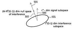
여기에서, 상기 그룹 빔포밍 행렬을 결정하는 단계는, 상기 통계적 채널 정보 및 원-링(one-ring) 채널 모델에 기반하여 그룹별 그룹 빔포밍 행렬이 서로 유사 직교하도록 상기 그룹 빔포밍 행렬을 결정하도록 구성될 수 있다. 이때, 상기 그룹 빔포밍 행렬들이 서로 유사 직교하도록 블록 대각화(block diagonalization)를 통하여 상기 그룹 빔포밍 행렬을 결정하도록 구성될 수 있다.Here, the step of determining the group beamforming matrix determines the group beamforming matrix such that the group beamforming matrix for each group is orthogonal to each other based on the statistical channel information and the one-ring channel model. It can be configured to. In this case, the group beamforming matrices may be configured to determine the group beamforming matrix through block diagonalization such that they are similarly orthogonal to each other.
여기에서, 상기 순시 채널 정보를 얻는 단계는, 상기 단말들에게 상기 그룹별 빔포밍 행렬이 적용된 CSI-RS 또는 상기 그룹별 빔포밍 행렬이 적용되지 않은 CSI-RS를 전송하는 단계 및 상기 단말들로부터 상기 그룹별 빔포밍 행렬이 적용된 CSI-RS 또는 상기 그룹별 빔포밍 행렬이 적용되지 않은 CSI-RS에 기초하여 측정된 순시 채널 정보를 피드백 받는 단계를 포함할 수 있다.Here, the step of obtaining the instantaneous channel information includes: transmitting CSI-RS to which the beamforming matrix for each group is applied or CSI-RS to which the beamforming matrix for each group is not applied to the terminals and from the terminals. The method may include receiving feedback of instantaneous channel information measured based on CSI-RS to which the beamforming matrix for each group is applied or CSI-RS to which the beamforming matrix for each group is not applied.
여기에서, 상기 순시 채널 정보를 얻는 단계는, 상기 단말들로부터 수신된 SRS(Sounding Reference Signal)에 기초하여 상기 순시 채널 정보를 측정하도록 구성될 수 있다.Here, the step of obtaining the instantaneous channel information may be configured to measure the instantaneous channel information based on the sounding reference signal (SRS) received from the terminals.
여기에서, 상기 순시 채널 정보는 송신상관행렬의 지배적인 고유 벡터 행렬에 관한 정보, 적응형 코드북 인덱스, 고정형 코드북 인덱스, SU-CQI(Single User CQI) 및 MU-CQI(Multi User CQI) 중 적어도 하나, 그룹 간섭 측정, RI(Rank Information) 중 적어도 하나를 포함할 수 있다. 이때, 상기 MIMO 전송 방법은, 상기 기지국이 SU-MIMO(Single User MIMO) 모드 또는 MU-MIMO(Multi User MIMO) 모드로의 동작 여부를 상기 단말에게 알려주는 단계를 추가로 포함하고, 상기 기지국과 단말이 SU-MIMO 모드로 동작할 경우에 상기 채널 정보는 상기 SU-CQI를 포함하며, 상기 기지국과 단말이 MU-MIMO 모드로 동작할 경우에 상기 채널 정보는 단말 별로 하나 이상의 상기 MU-CQI를 포함하도록 구성될 수 있다.Here, the instantaneous channel information is at least one of information on a dominant eigenvector matrix of a transmission correlation matrix, an adaptive codebook index, a fixed codebook index, a single user CQI (SU-CQI), and a multi user CQI (MU-CQI). , Group interference measurement, RI (Rank Information). At this time, the MIMO transmission method further includes the step of informing the terminal whether the base station is operating in a Single User MIMO (SU-MIMO) mode or a Multi User MIMO (MU-MIMO) mode, and the base station and the base station. When the terminal operates in the SU-MIMO mode, the channel information includes the SU-CQI, and when the base station and the terminal operate in the MU-MIMO mode, the channel information includes one or more of the MU-CQI for each terminal. It can be configured to include.
여기에서, 상기 순시 채널 정보에 기초하여 단말들을 스케줄링하는 단계는, 상기 기지국이 각 그룹과 각 클래스에 속한 단말들을 상기 그룹과 상기 클래스 별로 독립적으로 스케줄링 되도록 구성될 수 있다.
Here, the step of scheduling terminals based on the instantaneous channel information may be configured such that the base station independently schedules terminals belonging to each group and each class for each group and each class.
상술한 본 발명의 다른 목적을 달성하기 위한 본 발명은, 무선 통신 시스템에서 단말의 MIMO 수신 방법으로서, 상기 단말을 포함한 그룹에 대한 그룹 빔포밍 행렬이 적용된 신호를 수신하는 단계, 상기 그룹 빔포밍 행렬이 적용된 레퍼런스 신호 또는 상기 그룹 빔포밍 행렬이 적용되지 않은 레퍼런스 신호를 이용하여 순시 채널 정보를 생성하는 단계 및 상기 순시 채널 정보를 기지국으로 피드백하는 단계를 포함한 MIMO 수신 방법을 제공한다.The present invention for achieving another object of the present invention as described above, as a method for receiving MIMO of a terminal in a wireless communication system, receiving a signal to which a group beamforming matrix for a group including the terminal is applied, the group beamforming matrix Provided is a MIMO reception method including generating instantaneous channel information using the applied reference signal or the reference signal to which the group beamforming matrix is not applied, and feeding the instantaneous channel information to a base station.
여기에서, 상기 MIMO 수신 방법은 상기 단말이 상기 기지국으로부터 수신한 CSI(Channel State Information)-RS(Reference Signal)에 기초하여 측정된 통계적 채널 정보를 상기 기지국으로 피드백하는 단계를 추가로 포함하고, 상기 그룹 빔포밍 행렬은 상기 통계적 채널 정보를 이용하여 결정되도록 구성될 수 있다.Here, the MIMO receiving method further includes the step of feeding back, to the base station, statistical channel information measured based on Channel State Information (CSI) -RS (Reference Signal) received from the base station by the terminal, and the The group beamforming matrix may be configured to be determined using the statistical channel information.
여기에서, 상기 그룹 빔포밍 행렬은 상기 단말이 전송한 SRS(Sounding Reference Signal)에 기초하여 결정될 수 있다.Here, the group beamforming matrix may be determined based on a sounding reference signal (SRS) transmitted by the terminal.
여기에서, 상기 순시 채널 정보는 송신상관행렬의 지배적인 고유 벡터 행렬에 관한 정보, 적응형 코드북 인덱스, 고정형 코드북 인덱스, SU-CQI(Single User CQI) 및 MU-CQI(Multi User CQI) 중 적어도 하나, 그룹 간섭 측정, RI(Rank Information) 중 적어도 하나를 포함할 수 있다.Here, the instantaneous channel information is at least one of information on a dominant eigenvector matrix of a transmission correlation matrix, an adaptive codebook index, a fixed codebook index, a single user CQI (SU-CQI), and a multi user CQI (MU-CQI). , Group interference measurement, RI (Rank Information).
이때, 상기 MIMO 수신 방법은 상기 기지국이 SU-MIMO(Single User MIMO) 모드 또는 MU-MIMO(Multi User MIMO) 모드로의 동작 여부를 상기 단말에게 알려주는 단계를 추가로 포함하고, 상기 기지국과 단말이 SU-MIMO 모드로 동작할 경우에 상기 순시 채널 정보는 상기 SU-CQI를 포함하며, 상기 기지국과 단말이 MU-MIMO 모드로 동작할 경우에 상기 순시 채널 정보는 단말 별로 하나 이상의 상기 MU-CQI를 포함할 수 있다.At this time, the MIMO receiving method further includes the step of informing the terminal whether the base station is operating in a Single User MIMO (SU-MIMO) mode or a Multi User MIMO (MU-MIMO) mode, and the base station and the terminal. When operating in the SU-MIMO mode, the instantaneous channel information includes the SU-CQI, and when the base station and the terminal operate in the MU-MIMO mode, the instantaneous channel information includes one or more of the MU-CQI per terminal. It may include.
여기에서, 상기 통계적 채널 정보에 기초한 송신상관행렬이 서로 유사한 단말들이 하나의 그룹으로 분류될 수 있다. 이때, 상기 송신상관행렬의 유효 고유 벡터가 서로 유사한 단말들이 하나의 그룹으로 분류되면, 상기 송신상관행렬의 유효 고유 벡터간의 직교성이 높은 그룹들이 하나의 클래스로 분류될 수 있다.Here, UEs having similar transmission correlation matrices based on the statistical channel information may be classified into one group. In this case, when terminals having similar effective eigenvectors of the transmission correlation matrix are classified into one group, groups having high orthogonality among the effective eigenvectors of the transmission correlation matrix may be classified into one class.
본 발명에 따른 MIMO 송수신 방법에서는, 단말들 간의 송신상관행렬(transmit correlation matrix 혹은 채널공분산행렬)의 유사성을 이용하여, 단말들을 그룹으로 분류하고 그룹간에 유사 직교성(quasi-orthogonality)을 가지도록 함으로 그룹이 가상의 섹터로 동작하도록 하여, 그룹 별로 독립적인 스케쥴링이 가능해진다.In the MIMO transmission / reception method according to the present invention, by using the similarity of a transmission correlation matrix (transmit correlation matrix or channel covariance matrix) between terminals, the terminals are classified into groups and grouped to have quasi-orthogonality between groups. By operating as a virtual sector, independent scheduling is possible for each group.
또한, 본 발명에서는 상술된 가상 섹터 개념으로 전체 단말이 아닌 일부의 단말들에 대한 독립적 스케줄링이 가능해지므로(즉, 그룹별로 독립적인 스케쥴링)하므로 MU-MIMO 수행의 시스템 복잡도를 현저히 낮출 수 있다.In addition, in the present invention, since independent scheduling for some terminals instead of all terminals is possible (ie, independent scheduling for each group) with the above-described virtual sector concept, system complexity of performing MU-MIMO can be significantly reduced.
또한, 본 발명에서는 그룹 특정 레퍼런스 신호(GRS: Group-specific RS)를 도입함으로써, GRS를 통한 MU-CQI의 도입이 현실적으로 가능하여, 효과적인 MU-MIMO 수행이 가능해진다.In addition, in the present invention, by introducing a group-specific reference signal (GRS: Group-specific RS), it is possible to realistically introduce MU-CQI through GRS, thereby enabling effective MU-MIMO performance.
또한, 본 발명의 MIMO 송수신 방법을 이용할 경우, 고정형 코드북이 아닌 단말(혹은 단말 그룹)에 특정한 적응형 코드북을 사용할 수도 있으므로 LTE와 같은 고정형 코드북에 비해 더 좋은 성능을 보장할 수 있다.In addition, when using the MIMO transmission / reception method of the present invention, since a specific adaptive codebook may be used for a terminal (or terminal group) other than a fixed codebook, better performance can be guaranteed than a fixed codebook such as LTE.
또한, 본 발명에서는 GRS와 적응형 코드북으로 인해 FDD 방식 대규모안테나 시스템의 RS 및 단말 피드백 자원 부담을 실현 가능한 수준으로 감소시킬 수 있다.In addition, in the present invention, due to the GRS and the adaptive codebook, it is possible to reduce the RS and UE feedback resource burden of the FDD scheme large-scale antenna system to a feasible level.
도 1은 본 발명에 따른 MIMO 송수신 방법에서 사용자 그룹간의 공간 분리 개념을 설명하기 위한 개념도이다.
도 2는 3섹터 기지국에서 하나의 섹터 내에 위치한 단말의 위치 분포 및 스캐터(scatter)의 반지름 분포를 예시한 개념도이다.
도 3은 본 발명에 따른 FDD 방식 하향링크 MIMO 송수신 방법을 설명하기 위한 순서도이다.
도 4는 본 발명에 따른 MIMO 송수신 방법에서 단말들의 분류 예를 설명하기 위한 개념도이다.
도 5는 본 발명에 따른 MIMO 송수신 방법에서 블록 대각화의 개념을 설명하기 위한 개념도이다.
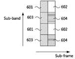
도 6은 본 발명에 따른 CSI 측정자원 또는 스케줄링 자원 후보의 할당에 대한 일 예를 설명하기 위한 개념도이다.
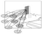
도 7은 3-D 빔포밍 기술의 개념을 설명하기 위한 개념도이다.1 is a conceptual diagram illustrating a concept of spatial separation between user groups in a MIMO transmission and reception method according to the present invention.
2 is a conceptual diagram illustrating a position distribution of a terminal located in one sector and a radius distribution of a scatter in a three-sector base station.
3 is a flowchart illustrating a FDD scheme downlink MIMO transmission and reception method according to the present invention.
4 is a conceptual diagram illustrating an example of classification of terminals in a MIMO transmission and reception method according to the present invention.
5 is a conceptual diagram illustrating a concept of block diagonalization in a MIMO transmission and reception method according to the present invention.
6 is a conceptual diagram illustrating an example of the allocation of a CSI measurement resource or scheduling resource candidate according to the present invention.
7 is a conceptual diagram for explaining the concept of a 3-D beamforming technique.
본 발명은 다양한 변경을 가할 수 있고 여러 가지 실시예를 가질 수 있는 바, 특정 실시예들을 도면에 예시하고 상세하게 설명하고자 한다.The present invention can be applied to various changes and can have various embodiments, and specific embodiments will be illustrated in the drawings and described in detail.
그러나, 이는 본 발명을 특정한 실시 형태에 대해 한정하려는 것이 아니며, 본 발명의 사상 및 기술 범위에 포함되는 모든 변경, 균등물 내지 대체물을 포함하는 것으로 이해되어야 한다.However, this is not intended to limit the present invention to specific embodiments, and should be understood to include all modifications, equivalents, and substitutes included in the spirit and scope of the present invention.
본 출원에서 사용한 용어는 단지 특정한 실시예를 설명하기 위해 사용된 것으로, 본 발명을 한정하려는 의도가 아니다. 단수의 표현은 문맥상 명백하게 다르게 뜻하지 않는 한, 복수의 표현을 포함한다. 본 출원에서, "포함하다" 또는 "가지다" 등의 용어는 명세서상에 기재된 특징, 숫자, 단계, 동작, 구성요소, 부품 또는 이들을 조합한 것이 존재함을 지정하려는 것이지, 하나 또는 그 이상의 다른 특징들이나 숫자, 단계, 동작, 구성요소, 부품 또는 이들을 조합한 것들의 존재 또는 부가 가능성을 미리 배제하지 않는 것으로 이해되어야 한다.The terms used in the present application are only used to describe specific embodiments, and are not intended to limit the present invention. Singular expressions include plural expressions unless the context clearly indicates otherwise. In this application, terms such as “include” or “have” are intended to indicate that a feature, number, step, operation, component, part, or combination thereof described in the specification exists, one or more other features. It should be understood that the existence or addition possibilities of fields or numbers, steps, operations, components, parts or combinations thereof are not excluded in advance.
다르게 정의되지 않는 한, 기술적이거나 과학적인 용어를 포함해서 여기서 사용되는 모든 용어들은 본 발명이 속하는 기술 분야에서 통상의 지식을 가진 자에 의해 일반적으로 이해되는 것과 동일한 의미를 가지고 있다. 일반적으로 사용되는 사전에 정의되어 있는 것과 같은 용어들은 관련 기술의 문맥 상 가지는 의미와 일치하는 의미를 가진 것으로 해석되어야 하며, 본 출원에서 명백하게 정의하지 않는 한, 이상적이거나 과도하게 형식적인 의미로 해석되지 않는다.Unless defined otherwise, all terms used herein, including technical or scientific terms, have the same meaning as commonly understood by a person skilled in the art to which the present invention pertains. Terms such as those defined in a commonly used dictionary should be interpreted as having meanings consistent with meanings in the context of related technologies, and should not be interpreted as ideal or excessively formal meanings unless explicitly defined in the present application. Does not.
본 출원에서 사용하는 '단말'은 이동국(MS), 사용자 장비(UE; User Equipment), 사용자 터미널(UT; User Terminal), 무선 터미널, 액세스 터미널(AT), 터미널, 가입자 유닛(Subscriber Unit), 가입자 스테이션(SS; Subscriber Station), 무선 기기(wireless device), 무선 통신 디바이스, 무선송수신유닛(WTRU; Wireless Transmit/Receive Unit), 이동 노드, 모바일 또는 다른 용어들로서 지칭될 수 있다. 단말의 다양한 실시예들은 셀룰러 전화기, 무선 통신 기능을 가지는 스마트 폰, 무선 통신 기능을 가지는 개인 휴대용 단말기(PDA), 무선 모뎀, 무선 통신 기능을 가지는 휴대용 컴퓨터, 무선 통신 기능을 가지는 디지털 카메라와 같은 촬영장치, 무선 통신 기능을 가지는 게이밍 장치, 무선 통신 기능을 가지는 음악저장 및 재생 가전제품, 무선 인터넷 접속 및 브라우징이 가능한 인터넷 가전제품뿐만 아니라 그러한 기능들의 조합들을 통합하고 있는 휴대형 유닛 또는 단말기들을 포함할 수 있으나, 이에 한정되는 것은 아니다.The 'terminal' used in the present application includes a mobile station (MS), a user equipment (UE), a user terminal (UT), a wireless terminal, an access terminal (AT), a terminal, a subscriber unit, It may be referred to as a subscriber station (SS), a wireless device, a wireless communication device, a wireless transmit / receive unit (WTRU), a mobile node, mobile or other terms. Various embodiments of the terminal are photographed such as a cellular phone, a smart phone having a wireless communication function, a personal digital assistant (PDA) having a wireless communication function, a wireless modem, a portable computer having a wireless communication function, a digital camera having a wireless communication function It may include a device, a gaming device having a wireless communication function, a music storage and playback home appliance having a wireless communication function, an internet home appliance capable of wireless Internet access and browsing, as well as a portable unit or terminals incorporating combinations of such functions. However, it is not limited thereto.
본 출원에서 사용하는 '기지국'은 일반적으로 단말과 통신하는 고정되거나 이동하는 지점을 말하며, 베이스 스테이션(base station), 노드-B(Node-B), e노드-B(eNode-B), BTS(base transceiver system), 액세스 포인트(access point), 릴레이(relay) 및 펨토셀(femto-cell) 등을 통칭하는 용어일 수 있다.
The 'base station' used in the present application generally refers to a fixed or moving point communicating with a terminal, and a base station, node-B (Node-B), e-node-B (eNode-B), and BTS. (base transceiver system), access point (access point), relay (relay) and may be a general term for femto-cells.
이하, 첨부한 도면들을 참조하여, 본 발명의 바람직한 실시예를 보다 상세하게 설명하고자 한다. 본 발명을 설명함에 있어 전체적인 이해를 용이하게 하기 위하여 도면상의 동일한 구성요소에 대해서는 동일한 참조부호를 사용하고 동일한 구성요소에 대해서 중복된 설명은 생략한다.
Hereinafter, preferred embodiments of the present invention will be described in detail with reference to the accompanying drawings. In order to facilitate the overall understanding in describing the present invention, the same reference numerals are used for the same components in the drawings, and duplicate descriptions for the same components are omitted.
본 발명에 따른According to the inventionMIMOMIMO 송수신 방법의 개요 Overview of sending and receiving method
본 발명에 따른 MIMO 송수신 방법이 적용되는 분야는 셀룰러 통신의 상향링크(uplink) 및 하향링크(downlink)이다.Fields to which the MIMO transmission and reception method according to the present invention are applied are uplink and downlink of cellular communication.
이하의 설명에서, 하나의 셀은 M개의 안테나를 가진 기지국과 각각 N개의 안테나를 갖는 K개의 사용자들(단말들)로 구성되고 각 단말의 송신안테나 상관도가 높다(즉, angle spread(AS)가 작다)고 가정한다. 일례로, 하향링크 도심 매크로 및 LOS(Line of Sight) 성분이 강한 채널환경에서는 송신안테나 상관도가 높게 형성이 된다.In the following description, one cell is composed of a base station having M antennas and K users (terminals) each having N antennas, and the transmission antenna correlation of each terminal is high (ie, angle spread (AS)). Is small). For example, in a channel environment in which a downlink urban center macro and a line of sight (LOS) component are strong, transmission antenna correlation is formed high.
또한 편의상, K명의 사용자가 송신안테나 상관도의 유사성에 따라 공간적으로 분리될 수 있는 G개의 그룹으로 나뉠 수 있고 각 그룹에는 K'명의 사용자가 있다고 가정한다. 편의상 모든 그룹이 동일한 수의 사용자로 구성됨을 가정한다.Also, for convenience, it is assumed that K users can be divided into G groups that can be spatially separated according to the similarity of transmission antenna correlation, and each group has K 'users. For convenience, it is assumed that all groups are composed of the same number of users.
본 발명에서 고려하는 채널 모델은 하기 수학식 1과 같다.
The channel model considered in the present invention is as shown in

여기서


본 발명이 제안하는 송신신호 모델은 하기 수학식 2와 같다.
The transmission signal model proposed by the present invention is as shown in Equation 2 below.

여기서


본 발명이 제안하는 수신신호 모델은 하기 수학식 3과 같다.
The received signal model proposed by the present invention is as shown in Equation 3 below.

여기서,

here,

여기서

here

그러면,
then,
상기 조건을 만족하도록
도 1은 본 발명에 따른 MIMO 송수신 방법에서 사용자 그룹간의 공간 분리 개념을 설명하기 위한 개념도이다.1 is a conceptual diagram illustrating a concept of spatial separation between user groups in a MIMO transmission and reception method according to the present invention.
도 1을 참조하면, 기지국은 M개의 안테나 소자들(10-1, 10-2, ..., 10-M)로 이루어진 대규모 안테나 어레이(10)를 구비한다. 그리고, K개의 활성 단말들(20-1, 20-2, ..., 20-K)이 존재하며 K개의 활성 단말들은 G개의 그룹으로 분류된다. 예컨대, 제 1 그룹(30-1)은 제 1 단말(20-1)과 제 2 단말(20-2)을 포함하며, 제 2 그룹(30-2)은 제 3 단말(20-3)을 포함한다. 제 G 그룹(20-G)은 제 K-1 단말(20-(K-1))과 제 K 단말(20-K)을 포함한다.Referring to FIG. 1, the base station includes a large-
이 때, 제 1 단말(20-1)과 제 2 단말(20-2)로 이루어진 제 1 그룹(30-1)의 채널행렬은
At this time, the channel matrix of the first group 30-1 consisting of the first terminal 20-1 and the second terminal 20-2 is
다음으로, 본 발명이 제안하는 MIMO 송수신 방법으로 얻을 수 있는 순시 채널행렬의 차원 감소를 설명한다. 먼저 K명의 사용자를 그룹 인덱스가 표현되도록 하기 수학식 6과 같이 인덱싱한다고 가정한다.
Next, the dimensional reduction of the instantaneous channel matrix obtained by the MIMO transmission and reception method proposed by the present invention will be described. First, it is assumed that K users are indexed as shown in Equation 6 below so that the group index is expressed.

한편, 수신 상관도가 클 때 수신기의 수신 빔포밍 혹은 결합(combining) 행렬을 사용하는 것이 효과적이다. 그러면, 본 발명의 송수신 방법에 의하여 사용자가 기지국으로 피드백해야할 순시 채널행렬의 차원은 하기 수학식 7로 표현되는 것과 같이 줄어듬을 알 수 있다.
On the other hand, it is effective to use the reception beamforming or combining matrix of the receiver when the reception correlation is large. Then, according to the transmission / reception method of the present invention, it can be seen that the dimension of the instantaneous channel matrix to be fed back to the base station is reduced as expressed by Equation 7 below.

여기서


here
다음은 편의상 그룹 g의 사용자들의 송신상관행렬이 동일하다고 가정하여 기지국에 주어진 통계적 정보와 안테나 배열에 따라
For convenience, assuming that the transmission correlation matrix of users of group g is the same, according to the statistical information and antenna arrangement given to the base station,
가. 기지국이 각 그룹의 송신상관행렬 정보를 아는 경우end. When the base station knows the transmission correlation matrix information of each group
그룹 g의 송신상관행렬의 고유 벡터(eigenvector)들은 사용자로부터 피드백받거나 상향링크 파일럿 신호를 이용하여 추정될 수 있다. 송신상관행렬은 통계적 정보이므로 기지국은 충분한 시간 간격을 두고 해당 정보를 피드백받아도 된다. 이 경우, 다음과 같은 다양한 형태의

대규모 안테나 어레이를 L개의 서브어레이(subarray)로 충분한 간격을 두고 배열하면 그룹g의 송신상관행렬은 블록대각행렬이 된다. 이 경우, 각 사용자가 피드백해야할 채널 정보는 대각선에 위치한 블록행렬의 고유벡터가 되므로 피드백 부담을 크게 줄일 수 있다. 분산형 안테나 시스템(distributed antenna system)은 상기 L개의 서브어레이로 나누어진 대규모 안테나 어레이의 특수한 경우에 해당하는 것으로 이해될 수 있다.If a large-scale antenna array is arranged at a sufficient interval with L subarrays, the transmission correlation matrix of group g becomes a block diagonal matrix. In this case, since the channel information to be fed back by each user becomes an eigenvector of the block matrix located diagonally, the feedback burden can be greatly reduced. It can be understood that the distributed antenna system corresponds to a special case of a large-scale antenna array divided into the L subarrays.
그룹g의 송신상관행렬의 실질적인 랭크(즉, 너무 작은 eigenvalue는 제외한 랭크)가 큰 경우, 그룹간의 송신상관행렬이 직교하도록 하기 위해서는 그룹의 수를 줄여서

If the actual rank of the transmission correlation matrix of group g (that is, the rank excluding too small eigenvalue) is large, the number of groups is reduced by making the transmission correlation matrix between groups orthogonal to each other.
나. 기지국이 각 그룹의 송신상관행렬 정보를 모르는 경우I. When the base station does not know the transmission correlation matrix information of each group
다음과 같은 형태의
미리 정해진 고정 빔포밍을 이용하여 가상의 섹터를 만들어 사용자 그룹을 공간 분리 할 수 있다. 이 때, 고정 빔포밍의 일례는 유니터리(unitary) 빔포밍에 기반을 둔 3GPP LTE Rel. 10 코드북일 수 있고, 사용자는 수신하는 빔 중에 가장 신호가 센 단일 및 복수개의 빔 인덱스를 기지국에 피드백할 수 있고 기지국은 해당 정보를 이용하여 사용자 그룹간 간섭이 적도록 적절히 스케줄링할수 있어야 한다.The user group can be spatially separated by creating a virtual sector using a predetermined fixed beamforming. At this time, an example of fixed beamforming is 3GPP LTE Rel based on unitary beamforming. It may be 10 codebooks, and the user may feedback single and multiple beam indices having the strongest signal among the received beams to the base station, and the base station should be able to appropriately schedule so that there is little interference between user groups using the corresponding information.
사용자가 송신상관행렬에서 추출한 송신 AS(Angle Spread) 및 AoD(Angle of Departure)를 기지국으로 피드백할 수도 있다.
The user may feedback the transmission AS (Angle Spread) and AoD (Angle of Departure) extracted from the transmission correlation matrix to the base station.
본 발명에서 제안하는 스케줄링의 핵심은 가능한
1단계는 모든 사용자들의 송신상관행렬의 고유 벡터(eigenvector)들 혹은 빔 인덱스 등의 정보를 이용하여
2단계는 그룹 내 사용자들이 피드백하는 순시 채널행렬
상술한 2단계 스케줄링으로 인해 시스템의 스케줄링 및 프리코딩 계산복잡도는 매우 크게 감소될 수 있다.
Due to the above-described two-step scheduling, the scheduling and precoding calculation complexity of the system can be greatly reduced.
하향링크 파일럿은 두 가지 형태를 가질 수 있다.The downlink pilot can take two forms.
첫 번째는 섹터의 전방위로 전송되는 일반적인 형태의 파일럿이다. 일례로 3GPP LTE와 동일한 구조의 파일럿 신호를 따를 수 있다.The first is a general type pilot transmitted in all directions of the sector. As an example, a pilot signal having the same structure as 3GPP LTE may be followed.
두 번째는 빔포밍 행렬이 곱해진 파일럿 신호이다. 여기서 두 번째 형태는 고정 빔포밍의 경우 사용자가 빔 인덱스를 전송하기 위해 필요한 파일럿 형태이다.The second is a pilot signal multiplied by a beamforming matrix. Here, the second form is a pilot form required for a user to transmit a beam index in the case of fixed beamforming.
대규모 MIMO 상향링크의 문제점은 수신채널 행렬의 차원이 큼으로 인해 수신 알고리즘의 계산 복잡도가 지수적으로 매우 커진다는 데 있다. 본 발명에서는 이 문제를 해결하는 상향링크의 다중사용자 MIMO 수신 방식으로 상술한 하항링크의 다중사용자 전송방식의 원리를 수신방식에 적용하여 얻을 수 있음을 제시한다. 즉 기지국은 상향링크 파일럿을 통해 모든 채널정보를 알고 있으므로 적절한 스케줄링을 통해 그룹간의 간섭이 없도록 수신 빔포밍을 하면 각 그룹의 수신벡터의 차원을 매우 줄어들고 수신 알고리즘의 계산복잡도를 구현 가능한 수준으로 낮출 수 있다.
The problem with the large-scale MIMO uplink is that the computational complexity of the reception algorithm is exponentially large due to the large dimension of the reception channel matrix. The present invention proposes that the above-described principle of the multi-user transmission method of the downlink can be obtained by applying to the reception method as the uplink multi-user MIMO reception method to solve this problem. That is, since the base station knows all the channel information through the uplink pilot, if the reception beamforming is performed so that there is no interference between groups through proper scheduling, the dimension of the reception vector of each group is greatly reduced and the computational complexity of the reception algorithm can be reduced to a level that can be implemented. have.
본 발명에 따른According to the inventionFDDFDD 방식 하향링크 Method downlinkMIMOMIMO 송수신 방법 How to send and receive
도 2는 3섹터 기지국에서 하나의 섹터 내에 위치한 단말의 위치 분포 및 스캐터(scatter)의 반지름 분포를 예시한 개념도이다. 이하의 설명에서 도 2가 병행 참조되어 본 발명이 설명된다.
2 is a conceptual diagram illustrating a position distribution of a terminal located in one sector and a radius distribution of a scatter in a three-sector base station. In the following description, the present invention is explained with reference to FIG. 2 in parallel.
가) 전체 수행 절차A) Complete procedure
도 3은 본 발명에 따른 FDD 방식 하향링크 MIMO 송수신 방법을 설명하기 위한 순서도이다.3 is a flowchart illustrating a FDD scheme downlink MIMO transmission and reception method according to the present invention.
도 3을 참조하면, 본 발명에 따른 FDD 방식 하향링크 MIMO 송수신 방법은, 무선 통신 시스템에서 기지국의 MIMO 전송 방법으로서, 적어도 하나의 단말에 대한 통계적 채널 정보를 얻는 단계(S310), 상기 통계적 채널 정보에 기초하여 상기 적어도 하나의 단말을 적어도 하나의 클래스(class)와 클래스에 종속된 적어도 하나의 그룹(group)으로 분류하는 단계(S320), 분할된 각 그룹에 대한 그룹 빔포밍 행렬을 결정하는 단계(S330), 상기 그룹 빔포밍 행렬에 기초한 그룹 빔포밍 전송을 상기 그룹에 속한 단말들에게 그룹별로 수행하고, 순시 채널 정보를 얻는 단계(S340) 및 상기 순시 채널 정보에 기초하여 상기 단말들을 스케쥴링하고, 상기 스케쥴링에 기초하여 상기 단말들에게 데이터를 전송하는 단계(S350)를 포함하여 구성될 수 있다.Referring to FIG. 3, the FDD scheme downlink MIMO transmission and reception method according to the present invention is a method for transmitting MIMO of a base station in a wireless communication system, obtaining statistical channel information for at least one terminal (S310), the statistical channel information Classifying the at least one terminal into at least one class and at least one group dependent on the class (S320), determining a group beamforming matrix for each divided group (S330), performing group beamforming transmission based on the group beamforming matrix to groups belonging to the group for each group, obtaining instantaneous channel information (S340), and scheduling the terminals based on the instantaneous channel information. , Transmitting data to the terminals based on the scheduling (S350).
이하에서는, 각 단계에 대한 간략한 설명을 하고, 후술되는 나) 내지 바) 절에서 각 단계를 구성하는 동작 및 구성요소들을 설명하기로 한다. 또한, 고정형 코드북 기반의 절차와 적응형 코드북 기분의 절차에 대해서도 후술한다.
Hereinafter, a brief description of each step will be made, and operations and components constituting each step will be described in sections b) to f) described later. In addition, the procedure based on the fixed codebook and the procedure of the adaptive codebook mood will be described later.
단계(S310)에서, 기지국은 통계적 채널정보를 적어도 하나의 단말로부터 피드백받거나 상향링크 SRS를 통해 측정할 수 있다. 통계적 채널 정보는 송신상관행렬(transmit correlation matrix), 송신상관행렬의 고유치(eigenvalue), 송신상관행렬의 고유벡터(eigenvector), AS(Angle Spread), AOD(Angle of Departure) 및 통계적 채널 정보를 의미하는 고정형 코드북에서 선택된 적어도 하나의 긴 주기 PMI(Precoding Matrix Indicator) 중 적어도 하나를 포함할 수 있다.In step S310, the base station may receive statistical channel information from at least one terminal or measure it through uplink SRS. Statistical channel information means transmit correlation matrix, eigenvalue of transmit correlation matrix, eigenvector of transmit correlation matrix, angle spread (AS), angle of departure (AOD) and statistical channel information It may include at least one of at least one long period PMI (Precoding Matrix Indicator) selected from the fixed codebook.
통계적 채널 정보는 기지국인 CSI-RS를 설정하여 단말들에게 전송하고, 기지국이 수신된 CSI-RS를 통하여 측정한 결과를 피드백 받는 것에 의해서 얻어지거나, 단말이 송신한 상향링크 SRS를 통하여 기지국이 직접 측정하도록 구성될 수 있다. 상기 통계적 채널 정보에 포함되는 각각의 정보들에 대해서는 후술된다.
Statistical channel information is obtained by setting the base station CSI-RS and transmitting it to the terminals, and the base station directly obtains the measured result through the received CSI-RS, or through the uplink SRS transmitted by the terminal. It can be configured to measure. Each of the information included in the statistical channel information will be described later.
단계(S320)에서, 기지국은 상기 통계적 채널 정보에 기초하여 상기 적어도 하나의 단말을 적어도 하나의 클래스와 클래스에 종속된 적어도 하나의 그룹으로 분류할 수 있다. 고정형 코드북 기반의 절차와 적응형 코드북 기반의 절차 중 어떠한 절차를 택하는지에 따라서 단계(S320)는 다르게 구성될 수 있다. 예컨대, 고정형 코드북 기반 절차를 따를 경우, 단말은 고정형 코드북에서 선택된 긴 주기 PMI를 통계적 채널 정보로서 피드백하게 되는데, 이는 단말이 자신이 속할 클래스와 그룹을 1차적으로 지정하는 것을 의미한다. 이때, 기지국은 단말이 선택한 클래스와 그룹을 무시하고 최적의 클래스와 그룹 분류를 2차적으로 재결정하여 단말들에게 통보할 수도 있다. 고정형 코드북 기반 절차를 취할 경우의 자세한 절차는 후술된다. 또한, 통계적 채널 정보와 그룹/클래스 분류에 대해서는 (나) 절에서 후술된다.
In step S320, the base station may classify the at least one terminal into at least one class and at least one group dependent on the class based on the statistical channel information. Step S320 may be configured differently according to which of the fixed codebook-based procedure and the adaptive codebook-based procedure is selected. For example, when a fixed codebook-based procedure is followed, the terminal feeds back the long period PMI selected from the fixed codebook as statistical channel information, which means that the terminal primarily designates a class and a group to which it belongs. At this time, the base station may ignore the class and group selected by the terminal and secondarily re-determine the optimal class and group classification to notify the terminals. Detailed procedures in the case of taking a fixed codebook-based procedure will be described later. In addition, statistical channel information and group / class classification will be described later in (B).
단계(S330)에서는 분할된 각 그룹에 대한 그룹 빔포밍 행렬을 결정하게 된다.In step S330, a group beamforming matrix for each divided group is determined.
이때, 고정형 코드북 기반의 절차에서는 미리 생성된 그룹 빔포밍 행렬들 중에서 그룹 빔포밍 행렬이 선택된다. 반면, 적응형 코드북 기반의 절차에서는 수신된 통계적 채널 정보에 기초하여 그룹 빔포밍 행렬이 생성된다. 그룹 빔포밍 행렬의 생성에 대해서는 (다)절에서 후술된다.
At this time, in a fixed codebook-based procedure, a group beamforming matrix is selected from among the previously generated group beamforming matrices. On the other hand, in the adaptive codebook based procedure, a group beamforming matrix is generated based on the received statistical channel information. The generation of the group beamforming matrix will be described later in (c).
단계(S340)에서, 기지국은 그룹 빔포밍 행렬에 기초한 그룹 빔포밍 전송을 상기 그룹에 속한 단말들에게 그룹별로 수행한다. 그리고, 기지국은 그룹 빔포밍이 적용된 CSI-RS 신호 또는 그룹 빔포밍이 적용되지 않은 CSI-RS로부터 측정된 순시 채널 정보를 단말들로부터 피드백받거나, 단말로부터 수신한 SRS을 통하여 순시 채널 정보를 직접 측정할 수 있다. 본 발명의 레퍼런스 신호들에 대해서는 (라)절에서 후술된다.In step S340, the base station performs group beamforming transmission based on the group beamforming matrix for each group of terminals belonging to the group. And, the base station receives feedback from the terminals of the instantaneous channel information measured from the CSI-RS signal to which the group beamforming is applied or CSI-RS to which the group beamforming is not applied, or directly measures the instantaneous channel information through the SRS received from the terminal. can do. The reference signals of the present invention will be described later in (d).
이때, 순시 채널 상태 정보는 암시적(implicit) 피드백 방식 또는 명시적(explicit) 피드백 방식을 이용하여 기지국으로 피드백될 수 있다.At this time, the instantaneous channel state information may be fed back to the base station using an implicit feedback method or an explicit feedback method.
순시 채널 정보는 송신상관행렬의 지배적인 고유 벡터 행렬에 관한 정보, 적응형 코드북 인덱스, 고정형 코드북 인덱스, SU-CQI(Single User CQI) 및 MU-CQI(Multi User CQI) 중 적어도 하나, 그룹 간섭 측정, RI(Rank Information) 중 적어도 하나를 포함할 수 있다.Instantaneous channel information is information on the dominant eigenvector matrix of the transmission correlation matrix, at least one of an adaptive codebook index, a fixed codebook index, a single user CQI (SU-CQI) and a multi user CQI (MU-CQI), and group interference measurement , RI (Rank Information).
순시 채널 정보의 구체적인 피드백 방법에 대해서는 고정형 코드북 기반 절차 및 적응형 코드북 기반 절차와 함께 후술된다.
The detailed feedback method of the instantaneous channel information will be described later together with the fixed codebook based procedure and the adaptive codebook based procedure.
마지막으로, 단계(S350)에서, 기지국은 각 그룹별로 해당 단말로부터 피드백받은 순시 채널정보와 스케줄링 알고리즘을 통해 서비스할 단말을 선정하고 제어신호와 데이터를 전송한다.Finally, in step S350, the base station selects a terminal to be serviced through instantaneous channel information and a scheduling algorithm fed back from the corresponding terminal for each group, and transmits a control signal and data.
이때, 기지국은 그룹별 빔포밍 행렬이 적용된 DM-GRS(Demodulation Group-specific RS)를 데이터와 함께 단말에게 전송하고, 단말은 DM-GRS를 이용하여 데이터를 복조할 수 있다.
At this time, the base station transmits a DM-GRS (Demodulation Group-specific RS) to which the beamforming matrix for each group is applied to the UE, and the UE can demodulate the data using the DM-GRS.
이하에서는, 본 발명에 따른 FDD 방식 하향링크 MIMO 송수신 방법 중, 고정형 코드북 기반의 기지국의 MIMO 전송 방법과 적응형 코드북 기반의 기지국의 MIMO 전송 방법을 보다 자세히 설명한다. 이하의 설명은 기지국의 관점에서 기술된 MIMO 전송 방법이나, 이에 상응하는 단말의 MIMO 수신 방법 유추하여 설명될 수 있다.
Hereinafter, among the FDD scheme downlink MIMO transmission and reception methods according to the present invention, a fixed codebook-based base station MIMO transmission method and an adaptive codebook-based base station MIMO transmission method will be described in more detail. The following description may be described by analogy with the MIMO transmission method described in terms of the base station, or the MIMO reception method of the corresponding terminal.
먼저, 고정형 코드북(fixed codebook) 기반의 절차를 설명한다.First, a procedure based on a fixed codebook will be described.
본 발명에 따른 FDD 방식 하향링크 MIMO 전송 방법의 고정형 코드북에 기반한 동작의 일 예는, CSI-RS를 전송하는 단계(1-1), 적어도 하나의 단말 각각으로부터 상기 CSI-RS를 통하여 결정된 각각의 단말이 속하는 클래스 및 그룹을 지정하는 정보를 수신하는 단계(1-2), 상기 정보에 기초하여 결정된 상기 단말들의 클래스와 그룹을 상기 단말들에게 통보하는 단계(1-3), 상기 결정된 클래스와 그룹에 기초하여, 각 그룹별 빔포밍 행렬을 생성하거나 선택하는 단계(1-4), 상기 그룹별 빔포밍 행렬이 적용된 CSI-RS를 상기 그룹별로 전송하는 단계(1-5), 상기 그룹별 빔포밍 행렬이 적용된 CSI-RS에 기초하여 측정된 채널정보를 상기 단말들로부터 수신하는 단계(1-6) 및 상기 채널 정보에 기초하여 상기 단말들을 스케쥴링하고, 상기 스케쥴링에 기초하여 상기 단말들에게 데이터를 전송하는 단계(1-7)를 포함하여 구성될 수 있다. 이하에서는, 단말로부터의 채널 정보 피드백이 암시적 채널 피드백(implicit channel feedback)으로 구성되는 경우를 가정하고 설명된다.
An example of the operation based on the fixed codebook of the FDD scheme downlink MIMO transmission method according to the present invention is a step (1-1) of transmitting a CSI-RS, each determined through the CSI-RS from each of at least one terminal. Receiving information specifying the class and group to which the terminal belongs (1-2), notifying the terminals of the class and group of the terminals determined based on the information (1-3), the determined class and Generating or selecting a beamforming matrix for each group based on a group (1-4), transmitting CSI-RS to which the beamforming matrix for each group is applied (1-5) for each group, for each group Receiving the channel information measured based on the CSI-RS to which the beamforming matrix is applied from the terminals (1-6) and scheduling the terminals based on the channel information, and to the terminals based on the scheduling. place It can comprise the steps (1-7) for transmitting the emitter. Hereinafter, it is assumed on the assumption that the channel information feedback from the terminal is configured with implicit channel feedback.
이하에서는, 각 단계에 대해 보다 상세히 설명하기로 한다.Hereinafter, each step will be described in more detail.
단계(1-1)에서, 기지국은 통상적인 CSI-RS를 설정하여 단말들에게 전송한다. 이때, 통상적인 CSI-RS는 후술되는 그룹별 빔포밍 행렬이 적용되지 않은 CSI-RS를 의미하는 것일 수 있다.In step 1-1, the base station establishes a conventional CSI-RS and transmits it to the terminals. In this case, the conventional CSI-RS may mean a CSI-RS to which a beamforming matrix for each group described below is not applied.
단계(1-2)에서, 단말은 기지국이 송신한 CSI-RS에 기초하여 최적의 클래스 및 그룹을 선정하고 선정된 클래스와 그룹을 지정하는 정보를 기지국으로 피드백한다. 상기 클래스와 그룹을 지정하는 정보는 하나 이상의 클래스 및 그룹을 지정하도록 구성될 수 있다. 단말은 단계(S310)에서 기지국이 송신한 CSI-RS를 이용해


한편, 단말이 긴 주기 PMI로서 클래스와 그룹을 지정하는 정보를 전송하기 위해서 기지국은 이용되는 고정형 코드북에 대한 정보를 단말에게 제공할 수 있다. 예컨대, 기지국의 안테나 개수 및 패턴, 기지국의 형태(urban/rural, macro/micro)에 따라서 다양한 고정형 코드북이 이용되는 경우, 기지국은 이용되는 고정형 코드북에 대한 정보를 단말에게 제공할 수 있다. 이러한 고정형 코드북에 대한 정보는 예컨대 방송 채널(PBCH)을 이용하여 단말에게 전달될 수 있다.Meanwhile, in order for the terminal to transmit information specifying a class and a group as a long period PMI, the base station may provide the terminal with information about a fixed codebook used. For example, when various fixed codebooks are used according to the number and pattern of antennas of the base station and the type of the base station (urban / rural, macro / micro), the base station may provide the terminal with information about the fixed codebook used. Information on the fixed codebook may be transmitted to a terminal using, for example, a broadcast channel (PBCH).
단계(1-3)에서, 기지국은 단말로부터 피드백받은 정보에 기초하여 단말들을 클래스와 그룹별로 분류한다. 이 과정에서 기지국의 클래스 및 그룹 재조정을 통해 단계(1-2)에서 단말이 보고한 클래스 및 그룹과는 다른 클래스 및 그룹이 단말에게 배정될 수 있다. 따라서, 기지국은 단계(1-2)에서 단말이 여러 개의 클래스 및 그룹을 지정하는 정보를 피드백하였거나, 기지국의 클래스 재조정을 통해 단말이 속한 클래스 및 그룹이 바뀐 경우에 결정된 단말의 클래스와 그룹을 해당 단말들에게 제어신호를 통해 알려 주게 된다.In step 1-3, the base station classifies the terminals into classes and groups based on the information fed back from the terminal. In this process, a class and group different from the class and group reported by the UE in step 1-2 may be assigned to the UE through re-adjustment of the base station's class and group. Therefore, the base station corresponds to the determined class and group of the terminal when the terminal feedbacks information specifying several classes and groups in step (1-2), or when the class and group to which the terminal belongs is changed through class rebalancing of the base station. Terminals are notified through a control signal.
기지국은 단계(1-4)에서 상기 결정된 클래스와 그룹에 기초하여, 각 그룹별 빔포밍 행렬을 생성하거나 선택한다. 이때, 기지국은 분류하고 각 그룹에 최적의 빔포밍 행렬을 생성하거나, 미리 생성된 빔포밍 행렬들 중에서 최적의 빔포밍 행렬을 그룹별로 선택할 수 있다. 기지국은 단계(1-5)에서 상기 그룹별 빔포밍 행렬이 적용된 CSI-RS를 상기 그룹별로 전송하게 된다.The base station generates or selects a beamforming matrix for each group based on the determined class and group in step 1-4. At this time, the base station can classify and generate an optimal beamforming matrix for each group, or select an optimal beamforming matrix for each group from among the previously generated beamforming matrices. In step (1-5), the base station transmits the CSI-RS to which the beamforming matrix for each group is applied for each group.
단계(1-6)에서 단말은 기지국이 전송한 그룹별 빔포밍 행렬이 적용된 CSI-RS를 이용하여 채널 정보를 측정하여 기지국으로 보고하게 된다. 이때, 채널 정보는 SU-CQI(Single User CQI) 및 MU-CQI(Multi User CQI) 중 적어도 하나, 짧은 주기의 PMI 및 RI(Rank Indicator)를 포함하여 구성될 수 있다.In step 1-6, the UE measures channel information using the CSI-RS to which the beamforming matrix for each group transmitted by the base station is applied and reports it to the base station. At this time, the channel information may be configured to include at least one of a single user CQI (SU-CQI) and a multi user CQI (MU-CQI), a short period PMI and a RI (Rank Indicator).
MU-CQI는 자기 신호 대 간섭 및 잡음의 비율(SINR)로 계산한다. 이 때, 간섭신호는 같은 그룹내의 간섭과 다른 그룹으로부터 오는 간섭을 모두 계산하여 반영한다. 기본적으로 단말은 모든 그룹의 모든 빔이 사용되는 것을 가정하여 간섭을 계산하다. 또한, 단말이 자신의 채널과 모든 그룹의 빔
마지막으로, 단계(1-7)에서 기지국은 상기 채널 정보에 기초하여 최적의 단말 조합을 찾아서 상기 단말들을 스케쥴링하고, 상기 스케쥴링에 기초하여 상기 단말들에게 데이터를 전송하게 된다.Finally, in step 1-7, the base station schedules the terminals by finding the optimal terminal combination based on the channel information, and transmits data to the terminals based on the scheduling.
단말의 MU-CQI를 기반으로 기지국에서 최적의 스케줄링을 수행할 경우 선택된 단말들은 그룹간의 간섭이 미미함을 의미한다. 그러므로 유사 직교하는 DM-GRS를 통해 다른 그룹의 선택된 단말들이 같은 자원의 DM-GRS를 통해 각자의 데이터를 복조할 수 있다. 다른 그룹간의 간섭은 유사직교 (quasi-orthogonal) 시퀀스로 추가로 줄이고 같은 그룹 내 다른 사용자간의 간섭은 직교 시퀀스를 사용하여 제거할 수 있다.
When the base station performs optimal scheduling based on the MU-CQI of the terminal, it means that the selected terminals have little interference between groups. Therefore, selected terminals of different groups can demodulate their data through DM-GRS of the same resource through DM-GRS that is orthogonal to each other. Interference between different groups is further reduced to a quasi-orthogonal sequence, and interference between different users in the same group can be eliminated using an orthogonal sequence.
한편, 단계(1-2)에서 언급된 긴 주기 PMI와 단계(1-6)에서 언급된 짧은 주기 PMI로 구성되는 고정형 코드북을 생성하는 설계 기준은 다음과 같다. 먼저 단일 극성 안테나(co-polarization)을 가정하여 기술하겠다.On the other hand, the design criteria for generating a fixed codebook consisting of the long period PMI mentioned in step (1-2) and the short period PMI mentioned in step (1-6) are as follows. First, a single polarity antenna (co-polarization) will be described.
고정형 코드북은 T개의 클래스와 각 클래스에 속하는 G개의 그룹으로 이뤄진다. 여기서 각 클래스 별로 다른 수의 그룹을 가질 수도 있다. 하나의 클래스를 구성하는 그룹의 고유벡터공간을 이루는 행렬
-각 그룹 고유벡터공간이 가능한 직교하도록 한다. 이는 그룹간 간섭을 줄이기 위함이다.-Make each group's eigenvector space as orthogonal as possible. This is to reduce interference between groups.
-각 그룹의 AoD가 가능한 균등 배치되도록 한다. 이는 단말의 고유벡터공간과 단말이 속한 그룹의 고유벡터 공간간에 불일치를 최소화하기 위함이다.-Make sure that the AoD of each group is placed as evenly as possible. This is to minimize the discrepancy between the eigenvector space of the terminal and the eigenvector space of the group to which the terminal belongs.
위와 같은 방식으로 얻은 각 클래스 별


For each class obtained in the same way as above
상술한 코드북은 단일 극성 안테나 (co-polarization)을 가정하였다. 한편, 이중 극성 안테나의 경우에는 두 개의 극성 안테나 어레이를 독립적으로 처리하여 하나의 극성 당 M/2개의 빔 벡터를 갖고 상기와 동일하게 긴 주기 PMI와 짧은 주기 PMI를 구성할 수 있다. 또한, LTE방식과 같이 co-phasing 파라미터를 두어 두 극성 안테나의 빔간에 constructive combining을 유도할 수도 있다. 그러나, 이 경우, 단말이 MU-CQI를 계산하기 위해 적어도 그룹 내 다른 사용자 간섭을 정확히 추정하도록 하여야 한다. 이를 위해 단말은 그룹 내 다른 사용자의 co-phasing 파라미터의 경우의 수에 따른 복수 개의 MU-CQI를 계산하고 각각에 co-phasing 파라미터를 피드백하여 기지국이 그룹 내 사용자들을 스케줄링하도록 한다. 이 때, 단말은 첫 번째 MU-CQI과 이것을 기준으로 나머지 MU-CQI의 offset만을 전송함으로 피드백 비트 수를 줄일 수 있다.The above codebook assumes a single polarization antenna (co-polarization). On the other hand, in the case of a dual polarity antenna, two polar antenna arrays can be independently processed to have M / 2 beam vectors per polarity to configure a long period PMI and a short period PMI as described above. In addition, constructive combining may be induced between beams of two polar antennas by placing co-phasing parameters as in the LTE method. However, in this case, it is necessary for the UE to accurately estimate at least other user interference in the group in order to calculate the MU-CQI. To this end, the UE calculates a plurality of MU-CQIs according to the number of cases of co-phasing parameters of other users in the group and feeds the co-phasing parameters to each of them to allow the base station to schedule users in the group. At this time, the UE can reduce the number of feedback bits by transmitting only the offset of the first MU-CQI and the remaining MU-CQI based on this.
상술한 절차는 종래의 CSI-RS를 기반으로 기술하였다. 한편, 종래의 CSI-RS를 긴 주기 CSI-RS와 짧은 주기 CSI-GRS로 대체할 수 있다. 여기서, CSI-GRS는
The above-described procedure has been described based on the conventional CSI-RS. Meanwhile, the conventional CSI-RS can be replaced with a long period CSI-RS and a short period CSI-GRS. Here, CSI-GRS
다음으로, 적응형 코드북(adaptive codebook) 기반의 절차를 설명한다.Next, a procedure based on an adaptive codebook will be described.
본 발명에 따른 FDD 방식 하향링크 MIMO 전송 방법의, 적응형 코드북 기반의 동작의 일 예는, 적어도 하나의 단말에 대한 통계적 채널 정보를 얻는 단계(2-1), 상기 통계적 채널 정보에 기초하여, 상기 적어도 하나의 단말들을 클래스와 그룹으로 분류하고, 각 그룹별 빔포밍 행렬을 생성하는 단계(2-2), 상기 그룹별 빔포밍 행렬이 적용된 CSI-RS를 상기 그룹별로 전송하는 단계(2-3), 상기 그룹별 빔포밍 행렬이 적용된 CSI-RS에 기초하여 측정된 채널정보를 상기 단말들로부터 수신하는 단계(2-4) 및 상기 채널 정보에 기초하여 상기 단말들을 스케쥴링하고, 상기 스케쥴링에 기초하여 상기 단말들에게 데이터를 전송하는 단계(2-5)를 포함하여 구성될 수 있다.
An example of the adaptive codebook-based operation of the FDD scheme downlink MIMO transmission method according to the present invention includes: obtaining statistical channel information for at least one terminal (2-1), based on the statistical channel information, Classifying the at least one terminal into classes and groups, and generating a beamforming matrix for each group (2-2), and transmitting CSI-RS to which the beamforming matrix for each group is applied for each group (2- 3) receiving channel information measured from the terminals based on CSI-RS to which the beamforming matrix for each group is applied (2-4), scheduling the terminals based on the channel information, and scheduling the It may be configured to include the step of transmitting data to the terminals (2-5).
이하에서는, 각 단계에 대해 보다 상세히 설명하기로 한다.Hereinafter, each step will be described in more detail.
단계(2-1)에서 기지국은 적어도 하나의 단말에 대한 통계적 채널 정보를 얻게 된다. 이때, 기지국은 단말이 송신하는 SRS(Sounding Reference Signal)를 이용하여 통계적 채널정보 획득을 측정하거나, 긴 주기의 CSI-RS를 단말에게 전송하고 단말이 측정한 통계적 채널 정보를 피드백 받을 수 있다. 이때, 통계적 채널 정보의 일 예는 단말의 고유 벡터 행렬일 수 있다. 또는, 통계적 채널 정보의 다른 예는 단말의 AS(Angle Spread)와 AoD(Angle of Departure)일 수 있다.In step 2-1, the base station obtains statistical channel information for at least one terminal. At this time, the base station may measure the acquisition of statistical channel information using a sounding reference signal (SRS) transmitted by the terminal, or transmit a long-term CSI-RS to the terminal and receive feedback of the statistical channel information measured by the terminal. In this case, an example of statistical channel information may be an eigen vector matrix of the terminal. Alternatively, other examples of statistical channel information may be an AS (Angle Spread) and an AoD (Angle of Departure) of the UE.
단계(2-2)에서, 기지국은 단계(2-1)에서 얻어진 통계적 채널 정보를 이용하여 기지국은 단말들을 클래스 및 그룹별로 분류하고 각 그룹에 최적의 빔포밍 행렬

단계(2-3)에서, 기지국은 단계(2-3)에서 생성된 빔포밍 행렬로 빔포밍된 CSI-GRS를 설정하여 방송한다. 여기서, CSI-GRS는
단계(2-4)에서 단말은 기지국이 전송한 그룹별 빔포밍 행렬이 적용된 CSI-RS를 이용하여 채널 정보를 측정하여 기지국으로 보고하게 된다. 이때, 채널 정보는 SU-CQI(Single User CQI) 및 MU-CQI(Multi User CQI) 중 적어도 하나, 짧은 주기의 PMI 및 RI(Rank Indicator)를 포함하여 구성될 수 있다.In step 2-4, the UE measures channel information using the CSI-RS to which the beamforming matrix for each group transmitted by the base station is applied and reports it to the base station. At this time, the channel information may be configured to include at least one of a single user CQI (SU-CQI) and a multi user CQI (MU-CQI), a short period PMI and a RI (Rank Indicator).
이때, 채널 정보 중 MU-CQI의 결정 방법과 채널 정보의 시그널링 방법은 앞서 설명된 고정형 코드북의 경우와 동일하므로 자세한 설명은 생략된다.At this time, since the method of determining the MU-CQI and the method of signaling the channel information among the channel information are the same as those of the fixed codebook described above, a detailed description is omitted.
마지막으로, 단계(2-5)에서 기지국은 상기 채널 정보에 기초하여 최적의 단말 조합을 찾아서 상기 단말들을 스케쥴링하고, 상기 스케쥴링에 기초하여 상기 단말들에게 데이터를 전송하게 된다.Finally, in step (2-5), the base station schedules the terminals by finding the optimal terminal combination based on the channel information, and transmits data to the terminals based on the scheduling.
단말의 MU-CQI를 기반으로 기지국에서 최적의 스케줄링을 수행할 경우 선택된 단말들은 그룹간의 간섭이 미미함을 의미한다. 그러므로 유사 직교하는 DM-GRS를 통해 다른 그룹의 선택된 단말들이 같은 자원의 DM-GRS를 통해 각자의 데이터를 복조할 수 있다. 다른 그룹간의 간섭은 유사직교 (quasi-orthogonal) 시퀀스로 추가로 줄이고 같은 그룹 내 다른 사용자간의 간섭은 직교 시퀀스를 사용하여 제거할 수 있다.
When the base station performs optimal scheduling based on the MU-CQI of the terminal, it means that the selected terminals have little interference between groups. Therefore, selected terminals of different groups can demodulate their data through DM-GRS of the same resource through DM-GRS that is orthogonal to each other. Interference between different groups is further reduced to a quasi-orthogonal sequence, and interference between different users in the same group can be eliminated using an orthogonal sequence.
상술한 CSI-GRS와 DM-GRS는 자원 절감을 위해 별도의 자원을 사용하는 것이 아니라, 하나의 GRS(Group-specific RS)로 통합되어 사용될 수도 있다. 즉, DM-GRS가 CSI-GRS의 역할을 할 수 있다. 이 경우, 상기 단말이 SU-MIMO로 동작하도록 지시받는다면, GRS를 통해 자신의 PDSCH를 복조할 수 있게 된다. 이를 해결하기 위해 기지국은 CSI용도의 GRS를 일례로 5ms 주기로 전송하는 서브프레임에서는 별도의 자원을 사용하여 SU-CQI기반의 유사 직교 DM-RS를 전송하여 단말이 PDSCH를 복조하도록 한다.
The above-described CSI-GRS and DM-GRS do not use separate resources for resource saving, but may be integrated and used as one group-specific RS (GRS). In other words, DM-GRS may act as CSI-GRS. In this case, if the terminal is instructed to operate as SU-MIMO, it is possible to demodulate its PDSCH through GRS. To solve this, the base station transmits SU-CQI-based pseudo orthogonal DM-RS using a separate resource in a subframe that transmits a GRS for CSI every 5 ms, for example, so that the UE demodulates the PDSCH.
나) 단말 분류 (B) Terminal classification (UEUEgroupinggrouping))
1) 통계적 채널정보1) Statistical channel information
본 절은 상술된 본 발명에 따른 MIMO 송수신 방법의 핵심 단계 중 하나인 통계적 채널정보에 따른 단말 분류에 대해 기술한다. 먼저 기지국은 CSI-RS를 통해 통계적 채널 정보를 피드백 받거나 상향링크 SRS를 통해 획득한다. 통계적 채널정보는 다음과 같은 형태를 취할 수 있다.
This section describes terminal classification according to statistical channel information, which is one of the key steps of the MIMO transmission and reception method according to the present invention. First, the base station receives feedback on statistical channel information through CSI-RS or acquires it through uplink SRS. Statistical channel information may take the following form.
-송신상관행렬(transmit correlation matrix 혹은 채널 공분산행렬)-Transmit correlation matrix or channel covariance matrix
-송신상관행렬의 유효한 고유치, 고유벡터-Valid eigenvalues and eigenvectors of the transmit correlation matrix
-AS(angle spread), AoD(angle of departure)-AS (angle spread), AoD (angle of departure)
-상기 단말의 통계적 채널 정보를 의미하는 긴 주기의 PMI(Precoding Matrix Indicator)
-Long-term PMI (Precoding Matrix Indicator) that means statistical channel information of the terminal
단말 채널의 통계적 특성인 송신상관행렬은 단말의 이동에 따라 매우 느리게 변하는 통계치이다. 이는 단말이 이동해야 주변의 scatterer(고정된 지형지물) 환경이 변하기 때문이다. 또한, MU-MIMO는 저속의 단말들에 한정되어 사용되는 것이 일반적이다. 송신상관행렬 추정 기법의 가장 단순한 형태는 one-ring 채널 모델을 가정한
The transmission correlation matrix, which is a statistical characteristic of the terminal channel, is a statistical value that changes very slowly according to the movement of the terminal. This is because the surrounding scatterer (fixed terrain) environment changes only when the terminal moves. In addition, MU-MIMO is generally used only for low-speed terminals. The simplest form of the transmission correlation matrix estimation technique assumes a one-ring channel model.
2) 단말 분류 절차2) Terminal classification procedure
단말 분류의 개요는 다음과 같다. 기지국은 단말

이와 같이 분류된 클래스들은 각기 다른 시간/주파수 자원을 사용하는 반면, 하나의 클래스 안의 그룹들은 같은 시간/주파수 자원이 할당된다. 클래스의 수를 T라 하자.
Classes classified in this way use different time / frequency resources, while groups in one class are assigned the same time / frequency resources. Let T be the number of classes.
서로의 고유벡터들간의 직교성이 높은 그룹들을 찾는 방법은 여러 구현방법이 있을 수 있다. 직교성이 높은 그룹의 고유벡터 행렬

There are several implementation methods for finding groups with high orthogonality between eigenvectors. Eigenvector matrix of groups with high orthogonality

본 장에서는 간단한

주어진 클래스 별 그룹 고유벡터 행렬에 대해 기지국은 각 단말의 고유벡터 행렬
For a given group eigenvector matrix, a base station eigenvector matrix of each terminal

여기서,
이 때, 유사성 수치가 기준치 이 때, 유사성 수치가 기준치
도 4는 본 발명에 따른 MIMO 송수신 방법에서 단말들의 분류 예를 설명하기 위한 개념도이다.4 is a conceptual diagram illustrating an example of classification of terminals in a MIMO transmission and reception method according to the present invention.
도 4는 앞서 도 2를 통하여 예시된 단말 및 scatterer 분포 예의 경우, 본 발명에 따라 단말들이 어떻게 분류될 수 있는지를 보여준다.FIG. 4 shows how the terminals can be classified according to the present invention in the case of the example of the terminal and scatterer distribution illustrated through FIG. 2 above.
도 4를 참조하면, 점선으로 도시된 원들은 클래스 1로 분류된 단말들의 위치와 scatterer의 원을 나타내고 실선으로 도시된 원들은 클래스 2의 단말들을 보여준다. 클래스 1은 4개의 그룹으로 이루어지고 클래스 2는 3개의 그룹으로 이뤄진다. 점선으로 도시된 선과 실선으로 도시된 선은 각 그룹의 직교 빔을 만드는 데 쓰이는 기준 각을 나타낸다.Referring to FIG. 4, circles shown by dotted lines indicate locations of terminals classified as
따라서, 각 클래스에 속한 단말의 원은 해당 점선 또는 실선으로 도시된 선 을 중심으로 위치하도록 단말 분류를 한 것을 볼 수 있다. 또한, 클래스 1 중에서 사선으로 채워진 원 두 개가 하나의 그룹을 이룬다는 것을 보여준다.
Therefore, it can be seen that the terminals of the terminals belonging to each class are classified into terminals so as to be centered around a line indicated by a corresponding dotted line or a solid line. It also shows that in
전체 단말의 수가 충분치 않을 경우, 클래스 당 단말의 수는 줄어 들고 더불어 그룹 당 단말의 수도 비례하여 줄어 든다. 이는 본 발명에 따른 MIMO 송수신 방법의 주파수 효율을 떨어뜨리는 결과를 가져오나, 다시 생각해 보면 셀 내 단말의 수가 적다는 것은 시스템 부하가 적어서 적은 주파수 효율로도 서비스에 문제가 없다는 것을 의미한다.If the total number of terminals is not sufficient, the number of terminals per class decreases and the number of terminals per group decreases proportionally. This results in a decrease in the frequency efficiency of the MIMO transmission and reception method according to the present invention, but when considered again, a small number of terminals in a cell means that there is no problem in service even with low frequency efficiency due to low system load.
또한, 본 발명이 적용되는 것과 같은 대규모 안테나 MIMO 기술은 많은 사용자를 동시에 같은 자원으로 서비스하는 것과 시스템이 피크 타임(peak time)의 과도한 부하를 견디도록 하여 QoE(사용자 체감지수)를 높이고자 하는 목적이 있으므로 우리는 단말의 수가 같은 자원으로 동시에 서비스하는 레이어 수 s보다 10배 정도 많다고 가정해도 무방할 것이다. 또한, 다중안테나 단말의 경우, 각 안테나를 별도의 사용자로 보고 스케줄링할 수도 있으므로 앞선 s에 대한 가정은 현실적이다.
In addition, a large-scale antenna MIMO technology, such as the present invention is applied, aims to increase QoE (user experience index) by simultaneously serving many users with the same resource and by allowing the system to withstand the excessive load of peak time. Because of this, we can safely assume that the number of terminals is 10 times larger than the number s of layers simultaneously serving the same resource. In addition, in the case of a multi-antenna terminal, it is also possible to view and schedule each antenna as a separate user, so the assumption about the preceding s is realistic.
상술한 단말 분류는 단말에 전송되는 송신신호의 ray가 AS만큼 퍼져있는 경우를 가정하여 기술하였다. 한편, 기지국 주변에 높은 빌딩과 같은 scatter가 있거나 마이크로 셀 기지국의 경우, 송신신호의 ray가 두 개의 이상의 AoD와 AS를 갖고 전송될 수도 있다. 이 경우, 해당 단말은 두 개 이상의 그룹에 속하게 되며 단말은 해당 그룹들로 분류되어 관리되고 각 그룹에서 필요한 단말 피드백을 수행하게 된다.
The above-described terminal classification is described on the assumption that the ray of the transmission signal transmitted to the terminal is spread as much as the AS. On the other hand, in the case of a scatter such as a tall building near the base station or in the case of a micro cell base station, the ray of the transmission signal may be transmitted with two or more AoDs and ASs. In this case, the corresponding terminal belongs to two or more groups, and the terminal is classified and managed into the corresponding groups and performs necessary terminal feedback in each group.
또한, 상술한 단말 분류는 기지국이 모든 단말의 통계적 채널정보를 알고 있다고 가정한다. 반면, 이러한 가정이 성립하지 못한다면, 기지국은 단말 분류를 위해 단말로부터 통계적 채널정보의 피드백을 필요로 하게 된다. 일례로, 기지국이 긴 주기의 CSI-RS를 전송하고 단말이 고정형 코드북을 기반으로 통계적 채널정보를 피드백하거나 AS와 AoD를 추정하여 피드백하는 방식으로 기지국은 단말의 통계적 채널정보를 획득한다. 기지국은 단말 피드백을 참고하여 상술한 단말 분류를 시행한다.In addition, the above-described terminal classification assumes that the base station knows statistical channel information of all terminals. On the other hand, if this assumption does not hold, the base station needs feedback of the statistical channel information from the terminal to classify the terminal. For example, the base station acquires the statistical channel information of the terminal by transmitting the CSI-RS of a long period and the terminal feedbacks statistical channel information based on a fixed codebook or estimates and feedbacks AS and AoD. The base station performs the above-described terminal classification with reference to terminal feedback.
이 때, 기지국의 판단에 의해 단말은 자신이 피드백한 AoD에 해당하는 그룹으로 분류되지 않고 시스템적으로 보다 적합한 다른 클래스 및 그룹에 분류될 수도 있다. 따라서, 이런 경우 기지국은 단말에게 자신이 속한 클래스와 그룹을 알려줘야 한다.
At this time, the UE may not be classified into a group corresponding to the AoD fed back by the base station, but may be classified into other classes and groups that are more systematically suitable. Therefore, in this case, the base station must inform the UE of the class and group to which it belongs.
다) 그룹C) Group빔포밍Beamforming 행렬 procession
1) 그룹 빔포밍 행렬 생성1) Create group beamforming matrix
상술된 단말 분류를 통해 선정된 그룹 고유벡터 행렬

Group eigenvector matrix selected through the above-described terminal classification

이러한 그룹 빔포밍 행렬은 그룹 분류를 통해 그룹 빔포밍 행렬이 서로 유사 직교하게 되어 수학식 8을 만족한다. 궁극적으로 그룹 빔포밍 행렬은 수학식 8을 만족할 수 있게 되어, 본 발명의 대규모 MU-MIMO 수행을 RS 및 단말 피드백 자원 부담을 최소화하며 가능하게 한다.
The group beamforming matrix satisfies Equation 8 because the group beamforming matrices are similarly orthogonal to each other through group classification. Ultimately, the group beamforming matrix can satisfy Equation (8), thereby enabling large-scale MU-MIMO performance of the present invention with minimal RS and UE feedback resource burden.
상술한 기본적인 그룹 빔포밍 행렬

Basic group beamforming matrix described above
2) 블록 대각화(Block Diagonalization)2) Block Diagonalization
도 5는 본 발명에 따른 MIMO 송수신 방법에서 블록 대각화의 개념을 설명하기 위한 개념도이다.5 is a conceptual diagram illustrating a concept of block diagonalization in a MIMO transmission and reception method according to the present invention.
도 5를 통하여 특정 그룹 g에 대한 블록 대각화를 개념적으로 설명된다.5, block diagonalization for a specific group g is conceptually described.
전체 M차원의 벡터 공간에서 그룹 g외에 다른 G-1개의 그룹의 고유벡터들은

다음 단계로 투영된 자기신호 부분공간에서의 고유벡터를 계산한다. 이러한 고유벡터는 다른 그룹의 고유벡터들과 직교성을 유지하면서 투영된 자신의 부분공간에서 최적의 빔포밍 행렬을 이룬다(어느 정도 왜곡이 있는 고유 빔포밍(eigen-beamforming) 에 해당하므로 암시적 채널 피드백 기반의 MU-MIMO 빔포밍 방식에서 최적에 가깝다고 할 수 있음).
The next step is to compute the eigenvectors in the projected magnetic signal subspace. These eigenvectors form an optimal beamforming matrix in their projected subspace while maintaining orthogonality with other groups of eigenvectors (as they correspond to eigen-beamforming with some degree of distortion, implicit channel feedback) It can be said to be close to optimal in the MU-MIMO beamforming based).
상술한 블록 대각화를 가능하게 하는 조건은 대략적으로 단지
The conditions for enabling the block diagonalization described above are approximately only
본 발명의 명세서에서는 암시적 단말 피드백을 중심으로 다루므로, 시스템의 활성 단말 수 K가 충분한 경우

Since the specification of the present invention focuses on implicit terminal feedback, when the number K of active terminals in the system is sufficient

한편, 활성 단말의 수가 적거나 스케줄러의 판단에 의해


On the other hand, the number of active terminals is small or the scheduler judges

여기서,


결국, 본 발명에 따른 빔포밍은 블록 다각화가 사용되지 않으면 수학식 10과 같이 고유(eigen) 빔포밍에 해당하고 수학식 2는 다음 수학식 13과 같이 표현된다.
In the end, the beamforming according to the present invention corresponds to eigen beamforming as in

여기서,


here,
상기

remind
라)la)레퍼런스reference 신호 ( signal (RSRS))
1) CSI-RS1) CSI-RS
본 발명에서의 CSI-RS는 통계적 채널정보의 피드백을 위해서 존재하고 순시 채널정보의 피드백을 위한 RS는 아래에 기술할 GRS이다. 따라서 만약 기지국이 상향링크 SRS를 통해 충분히 통계적 채널정보를 획득할 수 있다면 본 발명에서는 CSI-RS를 별도로 필요로 하지 않는다.The CSI-RS in the present invention exists for the feedback of the statistical channel information, and the RS for the feedback of the instantaneous channel information is the GRS described below. Therefore, if the base station can acquire statistical channel information sufficiently through the uplink SRS, the CSI-RS is not separately required in the present invention.
만약 SRS만으로 통계적 채널정보의 추정이 여의치 않다면 송신안테나 수 M을 최대 64개까지 고려할 때, 향후 LTE의 CRS(Cell-specific RS) 전송이 없어진다면 CRS 전송을 위해 사용되었던 자원들이 CSI-RS의 전송을 위해서 사용될 수 있을 것이다.If the estimation of the statistical channel information by SRS alone is not feasible, considering the maximum number of transmit antennas up to 64, if the cell-specific RS (CRS) transmission of LTE is lost in the future, the resources used for CRS transmission are CSI-RS transmission. Can be used for
이러한 CSI-RS은 단말의 순시 채널 추정 및 피드백이 아니고 통계적 채널 정보 추정 및 피드백을 위한 것으로 종래의 CSI-RS보다 훨씬 긴 주기로 전송해도 될 것이다.
The CSI-RS is not for instantaneous channel estimation and feedback of the terminal, but for statistical channel information estimation and feedback, and may be transmitted at a much longer period than the conventional CSI-RS.
2) Group-specific RS (GRS)2) Group-specific RS (GRS)
본 발명에서 제안하는 GRS는 각 그룹에 특정한 RS로서 종래의 LTE-Advanced의 DM-RS(또는, LTE의 UE-specific RS)처럼 빔포밍 행렬이 곱해진 RS이다. 이 때, 그룹 빔포밍 벡터


The GRS proposed in the present invention is a RS specific to each group, and is a multiplied beamforming matrix, such as a conventional LTE-Advanced DM-RS (or a UE-specific RS of LTE). At this time, the group beamforming vector
GRS는 LTE의 CSI-RS와 DM-RS 두 가지 기능을 다음과 같이 모두 수행한다.GRS performs both functions of LTE's CSI-RS and DM-RS as follows.
①CSI-RS 기능①CSI-RS function
GRS가 수행하는 CSI-RS로서의 역할은 단말들이 순시 채널정보를 피드백할 수 있도록 하기 위한 것이다. 본 발명에서 단말은 GRS를 통해
②DM-RS 기능②DM-RS function
GRS가 수행하는 DM-RS로서의 역할은 기지국에서 선택된 빔포밍(혹은 프리코딩)벡터를 단말에게 암시적으로 전달하는 것과 복조의 기준신호가 되는 것이다. 후술되겠으나, GRS는 단말에 특정한 RS로 볼 수 있다. 즉, 그룹 빔포밍 행렬

일례로, 단말이 랭크 2로 두 개의 CQI 및 PMI를 피드백한 경우, 기지국이 실제 몇 개 랭크와 어떤 PMI로 전송하는지를 알기 위해 단말은 3가지 경우(랭크 2여서 PMI1, PMI2 모두 사용, 랭크 1이고 PMI1 사용, 랭크1이고 PMI2 사용)에 대해 각각 검출 후 post SINR을 계산하여 올바른 랭크와 PMI를 알 수 있다.
For example, when the UE feeds back two CQIs and PMIs with rank 2, in order to know how many ranks and which PMI the base station actually transmits, the UE has 3 cases (rank 2, so both PMI1 and PMI2 are used,
GRS가 상관 복조(coherent demodulation)의 기준신호가 될 수 있는 것은 자명하다. 한 클래스에 속한 모든 그룹이 동일한 GRS 자원을 재사용할 수 있고 이 때 각 그룹별로 유사 직교 시퀀스를 사용한다. 또한, 그룹 내에 동시에 스케줄링된 단말들은 서로 다른 직교시퀀스로 구분한다. 일례로, 각 그룹에서 4개의 단말을 스케줄링하면 시퀀스 길이 4의 직교시퀀스가 필요하다.
It is obvious that GRS can be a reference signal for coherent demodulation. All groups belonging to one class can reuse the same GRS resource, and a similar orthogonal sequence is used for each group. Also, terminals simultaneously scheduled in a group are divided into different orthogonal sequences. For example, if four terminals are scheduled in each group, an orthogonal sequence of sequence length 4 is required.
GRS 자원 위치는 종래 DM-RS의 자원 위치를 사용할 수 있다. 또한, GRS의 자원은 그룹간의 자원 재사용으로 인해 종래처럼 스케줄링된 단말 수만큼 필요하지 않고 동시에 스케줄링된 단말 수를 그룹 수로 나눈 만큼의 자원이 소요된다. 일례로, 16개의 단말을 4개 그룹으로 나누어 동시에 스케줄링한다면 16개의 GRS자원이 아닌 4개의 GRS자원이 필요하게 된다(단말당 하나의 레이어를 할당하는 경우).
The GRS resource location can use a conventional DM-RS resource location. In addition, the resources of the GRS are not required as many as the number of scheduled terminals due to the reuse of resources between groups, and the resources of the scheduled terminals divided by the number of groups are required. For example, if 16 UEs are divided into 4 groups and scheduled at the same time, 4 GRS resources are needed instead of 16 GRS resources (when one layer is allocated per terminal).
GRS를 CSI-RS 기능으로 사용될 때의 장점으로 더 높은 주기성이 있다. 종래의 CSI-RS는 최소 전송 주기가 5ms임에 반해, GRS는 필요에 따라(최소가 아닌 고정된) 주기를 5ms 이하로 하는 데 무리가 없다. 이는 GRS는 DM-RS처럼 해당 클래스의 자원이 할당되는 서브프레임마다 전송이 되기 때문이다. 또한, DM-RS는 단말에 해당 자원이 할당될 때만 존재하지만, GRS는 같은 그룹의 다른 단말이 해당 자원을 할당 받을 때도 존재하므로 단말이 해당 자원을 할당 받지 않았을 때도 복조 기준신호로 채널 추정을 보다 정확히 할 수 있는 장점도 있다.
The advantage of using GRS as a CSI-RS function is higher periodicity. In the conventional CSI-RS, the minimum transmission period is 5 ms, whereas the GRS has no difficulty in setting the period to 5 ms or less as necessary (not fixed). This is because GRS is transmitted for each subframe to which resources of the corresponding class are allocated, such as DM-RS. In addition, DM-RS exists only when a corresponding resource is allocated to a terminal, but GRS also exists when another terminal of the same group is allocated a corresponding resource, so even when the terminal is not allocated the resource, channel estimation is compared with the demodulation reference signal. It has the advantage of being able to do exactly that.
한편, LTE-Advanced의 CSI-RS와 DM-RS의 형태를 따라서 GRS를 CSI-GRS와 DM-GRS로 별도로 두는 것도 고려할 수 있다. 이 경우, RS 오버헤드가 추가로 소요되는 문제가 있다. 또한, DM-GRS를 별도로 두면 기지국에서 단말이 피드백한 GBF의 빔포밍 벡터가 아닌 다른 프리코딩 행렬로 전송할 수 있으나, 이로 인한 이득은 매우 제한적일 것이므로 판단된다.
Meanwhile, it is also possible to consider separately setting GRS as CSI-GRS and DM-GRS according to the types of LTE-Advanced CSI-RS and DM-RS. In this case, there is a problem that RS overhead is additionally required. In addition, if the DM-GRS is set separately, the base station can transmit a precoding matrix other than the beamforming vector of the GBF fed back by the terminal, but it is determined that the gain will be very limited.
마) 단말 피드백E) Terminal feedback
본 문서에서는 암시적 단말 피드백을 위주로 단말 피드백을 서술하고 명시적 단말 피드백은 마지막에 간단히 서술하겠다.
In this document, terminal feedback will be described mainly on implicit terminal feedback, and explicit terminal feedback will be briefly described at the end.
1) 고유벡터 행렬1) Eigenvector matrix
앞서 설명된 바와 같이, 상향링크 SRS만으로 송신상관행렬을 추정하는 것이 여의치 않을 경우, 단말은 CSI-RS를 통해 송신상관행렬을 추정하여야 한다. 따라서, CSI-RS를 통해 단말은 송신상관행렬을 추정하여 그것의 지배적인 고유벡터행렬
-고유벡터행렬
-고유벡터행렬

-Unique vector matrix
2) 적응형 코드북2) Adaptive codebook
본 발명을 위한 암시적 단말 피드백의 코드북으로 LTE의 고정 코드북과는 달리 적응형(adaptive) 코드북이 이용될 수 있다. 즉, 코드북을 이루는 빔포밍 벡터가 그룹(등가적으로 단말)에 특정한 것들이기 때문에 각 그룹, 클래스 별로 다르고 시간(단말의 이동 및 활성/비활성)에 따라 매우 느리게 변할 수 있는 성질을 갖고 있다.
As a codebook of implicit terminal feedback for the present invention, an adaptive codebook may be used, unlike the fixed codebook of LTE. That is, since the beamforming vector constituting the codebook is specific to the group (equivalently to the terminal), it is different for each group and class and has a property that can be changed very slowly with time (movement and active / inactive of the terminal).
본 발명의 적응형 코드북은 하기 수학식 14로 표현될 수 있다.
The adaptive codebook of the present invention can be expressed by Equation 14 below.

여기서, 클래스 t에 해당하는 코드북 부분집합
Here, a subset of codebooks corresponding to class t

각 클래스 코드북


Each class codebook
다음은 이중극성 (cross-polarization) 안테나에 적합한 Rel. 10 듀얼 코드북에 맞추어 적응형 코드북을 제안하고 PMI 피드백 자원 소요량을 계산하겠다. 단말의 랭크가 1인 경우 (혹은 기지국이 각 단말에게 하나의 레이어만 할당하는 경우), 클래스 t, 그룹 g의 적응형 코드북은 다음과 같다.
The following is a Rel suitable for a cross-polarization antenna. 10 We will propose an adaptive codebook according to the dual codebook and calculate the PMI feedback resource requirements. When the rank of the terminal is 1 (or when the base station allocates only one layer to each terminal), the adaptive codebooks of class t and group g are as follows.

여기서

here
본 문서에서는 반드시 필요로 하지 않는 한, 모든 수식에서 클래스를 나타내는 윗첨자 (t)를 편의상 생략하고 기술하겠다.
In this document, superscripts (t) indicating classes in all formulas will be omitted for convenience.
3) 고정형 코드북3) Fixed codebook
본 발명의 또 다른 형태의 코드북으로 LTE와 같은 고정형 코드북을 설계할 수 있다. 상술한 적응형 코드북은 기지국이 모든 단말의 송신상관행렬은 안다는 가정하에서 기지국이 단말분류를 하여 현재 셀 내의 단말들에게 최적화된 코드북을 설계하여 GRS로 전송하고 이를 단말이 측정하여 자신에게 가장 좋은 빔포밍 벡터를 피드백하는 구조이다. 여기서 기지국이 SRS만을 이용하여 단말의 송신상관행렬을 추정하는 경우, 단말은 자신의 송신상관행렬을 알 필요도 없다.As another type of codebook of the present invention, a fixed codebook such as LTE can be designed. The above-described adaptive codebook is designed to be optimized for the terminals in the current cell by the base station classifying the terminal under the assumption that the base station knows the transmission correlation matrix of all terminals. It is a structure that feeds back the beamforming vector. Here, when the base station estimates the transmission correlation matrix of the terminal using only the SRS, the terminal does not need to know its transmission correlation matrix.
반면, 고정형 코드북은 기지국이 모든 단말의 송신상관행렬을 안다고 가정하지 않고 미리 정해진 제한적인 코드북이 설계되어 단말이 먼저 상당히 긴 주기의 CSI-RS를 통해 알게 되는 자신의 송신상관행렬을 추정하고 자신에게 코드북을 바탕으로 가장 좋은 빔포밍 벡터를 선택하여 피드백하는 방식이다. 본 코드북의 특징은 단말과 특정그룹간의 유사성 및 그룹들간의 직교성을 만족하도록 설계한다는 것이다.
On the other hand, the fixed codebook does not assume that the base station knows the transmission correlation matrix of all terminals, and a predetermined limited codebook is designed so that the terminal first estimates its transmission correlation matrix that is learned through a fairly long period of CSI-RS and sends it to itself. This is a method of selecting and feedback the best beamforming vector based on the codebook. The feature of this codebook is that it is designed to satisfy the similarity between a terminal and a specific group and orthogonality between groups.
일례로, 단말의 AS를 5도, 10도, 20도, 20도 이상의 4 단계로 나눠서 분류한다면, 각각의 AS에서 120도의 범위를 갖는 하나의 섹터에서 구성할 수 있는 (즉, 유사 직교하는) 그룹의 수는 4, 3, 2, 1이 될 수 있다. 즉, AS를 5도로 가정하면, 하나의 섹터에서 4개의 그룹에 해당하는 4개의 빔포밍 행렬을 만든다는 것이다. 이러한 빔포밍 행렬 집합(즉, 코드북)을 만드는 방식은 일례로 one-ring 채널모델을 가정하여 설계할 수 있다.
For example, if the AS of a terminal is classified into four phases of 5 degrees, 10 degrees, 20 degrees, and 20 degrees or more, each AS can be configured in one sector having a range of 120 degrees in each AS (i.e., orthogonal) The number of groups can be 4, 3, 2, 1. That is, if AS is assumed to be 5 degrees, it means that 4 beamforming matrices corresponding to 4 groups in one sector are generated. The method of creating a set of beamforming matrices (ie, codebook) can be designed by assuming a one-ring channel model as an example.
다음은 코드북 설계에 대한 것이다. 좋은 코드북을 설계하기 위해서는 척도를 명확히 해야 할 것이다. 일례로, 본 문서에서는 직교성에 대한 척도를 하기 수학식 17과 같이 정의한다.
Next is the codebook design. To design a good codebook, you need to clarify the scale. For example, in this document, a measure for orthogonality is defined as Equation 17 below.

여기서


here

상기 최적의
Above optimal
상술한 척도를 기준으로 AS가 10도인 경우를 일례로


As an example, the AS is 10 degrees based on the aforementioned scale.

여기서


here
주어진 AS, 송신안테나 수, 안테나간 거리와 상기 수식들로 구한 AoD


Given AS, number of transmitting antennas, distance between antennas, and AoD calculated by the above formulas
한편, 상술한 고정형 코드북으로 인한 긴 주기의 PMI 피드백은 다음과 같이 두 가지로 나뉜다. 먼저, 단말의 AS를 4개의 AS 범위로 나눈다면, 2비트를 소요한다. 각 AS에 대해 빔포밍 행렬


Meanwhile, the long-term PMI feedback due to the above-mentioned fixed codebook is divided into two types as follows. First, if the AS of the terminal is divided into four AS ranges, it takes 2 bits. Beamforming matrix for each AS
4) MU-CQI4) MU-CQI
본 채널정보 피드백은 상술한 긴 주기의 단말 피드백과는 달리 순시(instantaneous) 피드백이다. LTE의 CQI 피드백은 single-user(SU) MIMO를 baseline으로 하는 SU-CQI이다. 즉, 같은 자원에 스케줄링되는 다른 단말로 인한 간섭에 대한 정보가 없는 CQI를 피드백한다. 반면, MU-MIMO에서 다른 단말로 인한 간섭을 고려한 MU-CQI의 필요성과 이로 인한 이득이 매우 클 수 있음에 대해서 잘 알려져 있다. 따라서, 종래 LTE에서는 일례로 구현 상 predicted MU-CQI를 계산하여 MU-CQI를 대략이나마 추정하였으나, 정확한 MU-CQI와는 차이가 클 수 있음을 알 수 있다.
This channel information feedback is instantaneous feedback, unlike the terminal feedback of the long period described above. The LTE CQI feedback is a SU-CQI based on a single-user (SU) MIMO as a baseline. That is, the CQI having no information on interference due to other terminals scheduled on the same resource is fed back. On the other hand, it is well known that the necessity of MU-CQI in consideration of interference caused by other terminals in MU-MIMO and the benefit from this can be very large. Therefore, in the conventional LTE, as an example, in practice, predicted MU-CQI was calculated to estimate MU-CQI, but it can be seen that the difference from the correct MU-CQI may be large.
본 발명의 GRS 구조는 단말의 MU-CQI 피드백을 수월하게 한다. 앞서 언급된 바와 같이 단말


The GRS structure of the present invention facilitates MU-CQI feedback of the terminal. Terminal as mentioned above

여기서,
here,
상기 MU-CQI의 효율성은 기지국이 모든


The efficiency of the MU-CQI is that the base station
-기지국은 단말에게 제어신호를 통해 어떤


-단말 피드백 방법 중 적응형 코드북 방법에서 언급된 대로 LTE에서와 같이 코드북에 제한을 두어 고정된 특정 조합만을 사용하는 것이다.-As mentioned in the adaptive codebook method of the terminal feedback method, as in LTE, the codebook is limited and only a specific fixed combination is used.
MU-CQI를 피드백하는 데 소요되는 비트 수는 종래 LTE SU-CQI의 수치와 같게 할 수 있다.The number of bits required to feed back the MU-CQI may be the same as that of the conventional LTE SU-CQI.
한편, 단말이 피드백해야 하는 PMI는 상기 수학식 20을 최대화하는 인덱스 m에 해당한다.
Meanwhile, the PMI to be fed back by the terminal corresponds to an index m that maximizes
5) 그룹 간섭 측정5) Group interference measurement
상기 수학식 20의 MU-CQI계산은 다른 그룹의 간섭은 매우 미미하다는 것을 전제로 한다. 한편, 그룹의 빔포밍 벡터


The MU-CQI calculation of
이처럼 단말이 다른 그룹 간섭을 측정하여 MU-CQI계산에 고려하는 경우, 수학식 20은 하기 수학식 21로 대체된다.
When the UE measures other group interference and considers it in the MU-CQI calculation,

여기서,
here,
6) RI6) RI
앞서 언급한 대로, 본 발명은 전송안테나와 활성 단말의 수가 많은 시나리오에서 MU-MIMO에 최적화된 적응형 빔을 활용하기 때문에 기지국이 모든 MIMO 대상 자원에 대해 MU-MIMO로 스케줄링할 확률이 매우 높아진다. 이러한 MU-MIMO의 경우, 기지국은 통상적으로 단말의 랭크를 1 혹은 2로 제한하여 시스템 용량을 증대하고자 할 수 있다. 반대로, 단말의 수가 적은 경우 기지국은 단말이 SU-CQI로 피드백하도록 하여 시스템 용량을 증대하고자 할 수도 있다.
As mentioned above, since the present invention utilizes an adaptive beam optimized for MU-MIMO in a scenario where the number of transmitting antennas and active terminals is large, the probability that the base station schedules as MU-MIMO for all MIMO target resources is very high. In the case of such MU-MIMO, the base station may attempt to increase the system capacity by limiting the rank of the terminal to 1 or 2. Conversely, if the number of terminals is small, the base station may try to increase the system capacity by allowing the terminal to feed back to the SU-CQI.
기지국이 설정한 랭크가 2인 경우, 단말은 두 개의 코드워드에 해당하는 CSI 피드백을 하므로 기지국은 각 그룹에 속한 단말들의 피드백을 보고 스케줄링된 단말에게 실제 랭크 1로 전송할지 2로 전송할지 결정할 수 있다.
When the rank set by the base station is 2, since the terminal provides CSI feedback corresponding to two codewords, the base station can determine whether to transmit the
7) 명시적 단말 피드백7) Explicit terminal feedback
명시적 채널정보 피드백은 PMI대신 채널 행렬에 대한 직접적인 정보를 피드백하는 방식이다. 각 단말은 자신의 변형된 채널 벡터
Explicit channel information feedback is a method of feeding back direct information about a channel matrix instead of PMI. Each terminal has its own modified channel vector
기지국은 단말의 명시적 채널 피드백과 다른 셀 간섭을 측정한 CQI정보를 이용하여 임의의 알고리즘 (일례로 ZF 빔포밍) 으로 프리코딩 행렬
The base station precoding matrix using an arbitrary algorithm (for example, ZF beamforming) using CQI information that measures the explicit channel feedback of the UE and other cell interference.
바) 하향링크 제어신호F) Downlink control signal
종래 LTE-Advanced의 하향링크 제어신호 외에 다음과 같은 새로운 제어신호가 필요하다. 이 제어신호는 CSI 측정 자원 (즉, 스케줄링 자원 후보)에 대한 것이다.
In addition to the conventional LTE-Advanced downlink control signal, the following new control signal is required. This control signal is for a CSI measurement resource (ie, scheduling resource candidate).
대규모 송신안테나 시스템은 종래 시스템에 비해 매우 많은 활성 단말을 동시에 수용하는 것을 의미한다. LTE시스템은 단말로 하여금 전 주파수 대역에 대해 CSI를 측정하여 보고하도록 하는 것을 기본 모드 중 하나로 한다. 하지만, 활성 단말의 수가 매우 커진다면 이러한 CSI 피드백 오버헤드는 시스템에서 감당하기 어려울 수 있다. 따라서, 본 발명에서는 이러한 문제를 해결하기 위해서 CSI 측정 자원을 클래스 별로 할당하는 방법을 적용할 수 있다.
A large-scale transmission antenna system means accommodating a large number of active terminals simultaneously compared to a conventional system. The LTE system is one of the basic modes for the UE to measure and report CSI for all frequency bands. However, if the number of active terminals becomes very large, this CSI feedback overhead may be difficult to handle in the system. Therefore, in the present invention, a method of allocating CSI measurement resources for each class can be applied to solve this problem.
LTE-Advanced 하향링크 MIMO 전송방식에서 기지국은 단말의 CSI 측정 자원을 RRC 메시지로 보내고 이 정보는 단말이 활성 상태 중에는 바뀌지 않는다. 반면, 본 발명에서는 단말을 클래스 별로 분류 (pre-scheduling)하고 단말의 해당 클래스는 단말의 이동 혹은 클래스 간의 부하 밸런싱(load balancing)에 따라 변경될 수 있다.In the LTE-Advanced downlink MIMO transmission method, the base station sends the CSI measurement resource of the terminal as an RRC message, and this information does not change while the terminal is active. On the other hand, in the present invention, the terminals are pre-scheduled for each class and the corresponding class of the terminal may be changed according to the movement of the terminal or load balancing between classes.
또한, 기지국은 클래스 별로 별도의 자원을 할당하므로 단말이 활성 상태 중에서 클래스가 바뀜에 따라 CSI 측정 및 스케줄링 자원이 바뀔 수 있다. LTE-Advanced와 달리 CSI 측정자원이 활성상태 중에 바뀔 수 있으므로 본 발명에 따른 CSI 측정자원 제어신호는 RRC 메시지보다는 MAC 메시지 성격에 부합한다.In addition, since the base station allocates separate resources for each class, CSI measurement and scheduling resources may be changed as the class changes among the active states of the terminal. Unlike LTE-Advanced, the CSI measurement resource can be changed during the active state, so the CSI measurement resource control signal according to the present invention conforms to the nature of the MAC message rather than the RRC message.
도 6은 본 발명에 따른 CSI 측정자원 또는 스케줄링 자원 후보의 할당에 대한 일 예를 설명하기 위한 개념도이다.6 is a conceptual diagram illustrating an example of the allocation of a CSI measurement resource or scheduling resource candidate according to the present invention.
도 6은 클래스의 수가 4인 경우이다. 클래스 별로 별도의 자원이 할당된 경우를 예시하고 있다. 예컨대, 왼쪽 사선으로 구별된 자원(601)이 클래스 1에 할당되고, 오른쪽 사선으로 구별된 자원(603)이 클래스 3에 할당될 수 있다. 클래스 수와 할당자원 크기는 단말의 분포에 따라 semi-static(대략 수 분 ~ 수십 분)하게 변할 수 있다.
6 is a case where the number of classes is four. It illustrates the case where separate resources are allocated for each class. For example, the
본 발명에서 CSI 측정자원 제어신호를 시그널링하는 방법에는 다음과 같이 두 가지 방법이 있을 수 있다.In the present invention, there are two methods for signaling a CSI measurement resource control signal as follows.
1) 클래스 ID(RNTI)를 이용하는 경우1) When using class ID (RNTI)
기지국은 각 단말에 MAC 메시지를 통해 모든 클래스 별 CSI 측정 자원 혹은 스케줄링 자원 맵/모드를 전달하고 각 단말에게 자신의 클래스 RNTI를 알려준다. 단말의 이동 등에 따라 단말의 클래스가 바뀌면 기지국은 MAC 메시지로 바뀐 클래스 RNTI만 시그널링하고 단말은 해당 클래스의 자원을 알 수 있다. 또한, 클래스 RNTI가 있으면 클래스, 그룹 별로 multicast가 가능할 것이다.The base station transmits CSI measurement resource or scheduling resource map / mode for each class through a MAC message to each terminal and informs each terminal of its class RNTI. When the class of the terminal changes according to the movement of the terminal, the base station signals only the class RNTI changed to the MAC message, and the terminal can know the resource of the corresponding class. Also, if there is a class RNTI, multicast will be possible for each class and group.
2) 클래스 ID(RNTI)를 이용하지 않는 경우2) When class ID (RNTI) is not used
기지국은 각 단말이 해당하는 클래스의 CSI 측정자원을 MAC메시지로 알려주며, 단말의 이동 등에 따른 클래스 변화에 따라 바뀐 클래스의 CSI 측정자원을 알려준다.
The base station notifies the CSI measurement resource of the corresponding class by the MAC message, and notifies the CSI measurement resource of the changed class according to the class change according to the movement of the terminal.
상기 1)의 경우, 단말이 자신의 GRS 시퀀스를 알기 위해 그룹ID(RNTI)를 필요로 한다. 기지국은 셀ID, 그룹ID를 포함하는 GRS 시퀀스 결정식을 구성하여 단말이 셀ID, 그룹ID 만으로 GRS시퀀스를 알도록 할 수 있다. 클래스마다 별도의 자원을 사용하므로 GRS 시퀀스를 클래스 ID 별로 구분할 필요는 없다. 또한, 본 발명에서는 GRS를 단말에 특정한 적응형 코드북을 사용함에 따라 PMI와 GRS 시퀀스가 일대일 맵핑된다. 앞서 GRS를 설명한 부분에서 서술된 대로 본 발명에서는 단말이 암시적으로 자신의 빔포밍 행렬을 알 수 있다. 따라서 GRS 시퀀스는 종래 DM-RS 시퀀스와 달리 PDCCH를 통해 동적으로 할당될 필요가 없다.
In the case of 1), the UE needs a group ID (RNTI) to know its GRS sequence. The base station may configure the GRS sequence determination formula including the cell ID and the group ID to allow the UE to know the GRS sequence using only the cell ID and the group ID. Since each class uses a separate resource, it is not necessary to classify the GRS sequence by class ID. In addition, in the present invention, PMI and GRS sequences are mapped one-to-one by using an adaptive codebook specific to the GRS terminal. In the present invention, as described in the above description of the GRS, the UE can implicitly know its beamforming matrix. Therefore, the GRS sequence does not need to be dynamically allocated through the PDCCH, unlike the conventional DM-RS sequence.
한편, 본 발명에서 RI는 PMI처럼 기지국이 단말에게 PDCCH를 통해 명시적으로 알려줄 필요가 없을 수 있다. 기지국은 단말이 피드백한 RI를 참고하여 해당 단말에게 실제 전송할 레이어 수를 결정하고 전송하게 된다. 단말은 PMI에 대한 간단한 검출 테스트와 같은 과정으로 post-SINR을 계산하여 실제 기지국에서 전송된 레이어 수를 알 수 있다.
On the other hand, in the present invention, RI may not need to explicitly inform the UE of the base station through the PDCCH like the PMI. The base station determines and transmits the number of layers to be actually transmitted to the corresponding terminal by referring to the RI fed back by the terminal. The UE can know the number of layers actually transmitted from the base station by calculating post-SINR in the same process as a simple detection test for PMI.
사) 스케줄링G) Scheduling
본 발명에서 그룹은 그룹 분류에 의한 가상의 섹터로 볼 수 있다. 즉, 기지국은 스케줄링을 각 클래스 및 그룹 별로 독립적으로 수행하면 된다. 기지국은 MU-CQI 부분에서 설명한 바와 같이 특정 그룹에 속한 모든 활성 단말로부터 MU-CQI를 피드백받는다. 기지국이 운영하는 스케줄링은 각 단말의 공정성(fairness)을 나타내는 가중치(weight)가 이 MU-CQI에 곱해진 utility function을 최대화 하는 단말의 조합을 찾는 과정에 해당한다. 일례로, 일부 단말이 동일한 빔포밍 벡터(PMI)를 피드백하거나 복수개의 빔포밍 벡터를 피드백하는 경우에도 각 단말 별로 가중치(fairness를 위해 일반적으로 특정 단말의 누적된 수신 데이터 량이 많으면 그에 비례하여 해당 가중치가 작게 됨)가 곱해져서 utility function을 최대화 하는 단말의 조합을 찾으면 된다.
In the present invention, a group can be viewed as a virtual sector by group classification. That is, the base station can perform scheduling independently for each class and group. As described in the MU-CQI section, the base station receives MU-CQI feedback from all active terminals belonging to a specific group. The scheduling operated by the base station corresponds to a process of finding a combination of terminals maximizing a utility function multiplied by this MU-CQI, a weight representing fairness of each terminal. For example, even when some UEs feed back the same beamforming vector (PMI) or multiple beamforming vectors, the weight of each UE (for fairness, if the accumulated amount of received data of a specific UE is large, the corresponding weight is proportionally proportional to it) Is reduced) to find the combination of terminals that maximize the utility function.
아)3-DA) 3-D빔포밍Beamforming
본 명세서는 지금까지 대규모 송신안테나를 수평축으로 나열하는 빔포밍만을 고려하였다. 이와 더불어 안테나 배열을 수직 축으로 늘리는 대규모 송신안테나 시스템도 고려할 수 있고 수평축과 수직축 공간 모두를 활용한 빔포밍 기술을 3-D (3차원) 빔포밍이라고 한다.So far, this specification only considers beamforming in which large-scale transmission antennas are arranged on a horizontal axis. In addition, a large-scale transmission antenna system that extends the antenna array to the vertical axis can be considered, and a beamforming technique utilizing both horizontal and vertical axis spaces is called 3-D (three-dimensional) beamforming.
도 7은 3D 빔포밍 기술의 개념을 설명하기 위한 개념도로서, 도심 고층 빌딩에 위치한 매크로 기지국에 의하여 수평축과 수직축 공간 모두를 활용한 빔포밍을 수행하는 개념을 도시한 것이다.FIG. 7 is a conceptual diagram for explaining the concept of 3D beamforming technology, and shows a concept of performing beamforming using both horizontal and vertical axis spaces by a macro base station located in an urban high-rise building.
본 절에서는 앞선 수평축 빔포밍을 감안한 본 발명의 MIMO 전송 개념을 수직축으로도 확장한 3-D 빔포밍 기술을 소개한다.This section introduces the 3-D beamforming technology that extends the MIMO transmission concept of the present invention in consideration of the previous horizontal axis beamforming to the vertical axis.
먼저, 3-D 빔포밍을 위한 CSI-RS의 구조와 PMI 피드백 스킴(scheme)에 대해서 간략히 설명한다.First, the structure of the CSI-RS for 3-D beamforming and the PMI feedback scheme will be briefly described.
긴 주기 CSI-RS 구조의 경우, 기지국이 2차원 안테나 어레이로 인해 수평축/수직 축으로 각각 복수 개의 어레이가 있어도 단말의 통계적 채널특성인 고유벡터 행렬은 수평축으로 하나, 수직 축으로 하나가 된다고 볼 수 있다. 따라서, 긴 주기의 CSI-RS 가 모든 2차원 안테나 요소마다 있을 필요가 없고 수평축으로 하나의 행, 수직 축으로 하나의 열이 사용되어 전송되면 된다.In the case of a long period CSI-RS structure, the eigenvector matrix, which is a statistical channel characteristic of the terminal, is one on the horizontal axis and one on the vertical axis, even if the base station has a plurality of arrays each on the horizontal axis / vertical axis due to the 2D antenna array. have. Therefore, a long period CSI-RS need not be present for every 2D antenna element, and only one row on the horizontal axis and one column on the vertical axis are used for transmission.
짧은 주기 CSI-RS 구조의 경우, 단말의 고유벡터 행렬은 상술한 바와 같은 구조를 가지나, 짧은 주기의 페이딩 채널은 수평축/수직 축으로 각각 복수 개의 어레이가 다를 수 있다. 따라서, 짧은 주기의 CSI-RS는 모든 2차원 안테나 요소마다 전송될 필요가 있다.In the case of the short-period CSI-RS structure, the eigenvector matrix of the terminal has the structure as described above, but the fading channel of the short-period is a horizontal axis / vertical axis, and a plurality of arrays may be different from each other. Therefore, the CSI-RS of a short period needs to be transmitted for every 2D antenna element.
긴 주기 PMI 피드백의 경우, 긴 주기 PMI는 긴 주기 CSI-RS에 맞춰 수평축으로 하나의 긴 주기 PMI (수평축 클래스 및 그룹 ID), 수직 축으로 하나의 긴 주기 PMI (수직축 클래스 및 그룹 ID)로 구성된다.
For long period PMI feedback, the long period PMI consists of one long period PMI (horizontal axis class and group ID) on the horizontal axis and one long period PMI (vertical axis class and group ID) on the vertical axis in line with the long period CSI-RS. do.
짧은 주기 PMI 피드백의 경우, 짧은 주기 PMI는 모든 2차원 안테나 요소마다 다를 수 있으므로 수평축으로 복수개의 짧은 주기 PMI, 수직 축으로 복수 개의 짧은 주기 PMI가 피드백된다.
In the case of short-period PMI feedback, since the short-period PMI may be different for every 2D antenna element, a plurality of short-period PMIs on the horizontal axis and a plurality of short-period PMIs on the vertical axis are fed back.
1) 채널 모델1) Channel model
2차원 안테나 배열의 열(수평축) 크기를 M, 행(수직축) 크기를 N이라 하고, 상기 그림은 하나의 클래스에 대한 3D 빔포밍의 예시이다. 본 명세서에서는 편의상 하나의 클래스만 생각하고 활성 단말들을 수직 축으로 L개의 수직 그룹, 수평축으로 G개의 수평 그룹으로 공간 분리할 수 있다고 하자. 수직축, 수평축 각각의 송신상관행렬을
The column (horizontal axis) size of the 2D antenna array is called M, and the row (vertical axis) size is called N, and the figure above is an example of 3D beamforming for one class. For convenience, in this specification, it is assumed that only one class is considered and the active terminals can be spatially separated into L vertical groups on the vertical axis and G horizontal groups on the horizontal axis. Transmit correlation matrix of vertical axis and horizontal axis

이런 경우 Kronecker(보다 정확히는 one-ring) 채널 모델을 3차원 채널 모델로 확장하면, 3차원 상관행렬
In this case, if the Kronecker (more precisely, one-ring) channel model is extended to a 3D channel model, the 3D correlation matrix

상기 3차원 송신상관행렬의 의해, 수직/수평 그룹 (g,l)에 속한 단말의 채널 벡터는 하기 수학식 24와 같이 표현된다.
By the 3D transmission correlation matrix, a channel vector of a terminal belonging to the vertical / horizontal group (g, l) is expressed as Equation 24 below.

2) 빔포밍 행렬2) Beamforming matrix
3-D 송신벡터는 하기 수학식 25와 같이 표현된다.
The 3-D transmission vector is expressed by Equation 25 below.

여기서,


here,

상기 수학식 26의 관계를 이용하여 수직/수평 그룹 (l,g)의 수신 벡터는 하기 수학식 27과 같이 표현된다.
The reception vector of the vertical / horizontal group (l, g) using the relationship of Equation 26 is expressed as Equation 27 below.

여기서,
here,

상기 수식에 의해 본 발명에 따른 2차원 빔포밍 행렬에서처럼 최적의 3차원 빔포밍 행렬은 다음과 같다.
The optimal 3D beamforming matrix as in the 2D beamforming matrix according to the present invention by the above formula is as follows.

3) 코드북3) Codebook
3차원 빔포밍의 그룹은 2차원 빔포밍의 (수평축) 그룹이 수직/수평축 그룹으로 세분화된 것에 해당하므로 클래스 t의 코드북은 수직축을 포함하여 다음과 같이 표현할 수 있다.
The group of 3D beamforming corresponds to that the (horizontal axis) group of 2D beamforming is subdivided into vertical / horizontal axis groups, so the codebook of class t can be expressed as follows, including the vertical axis.

수학식 25에 나타나듯이, 3차원 빔포밍 행렬은 다음과 같이 표현된다.
As shown in Equation 25, the three-dimensional beamforming matrix is expressed as follows.

여기서,

here,

일례로
As an example
마지막으로, 단말 분류, GRS, 단말 피드백 등은 2차원 빔포밍과 동일한 개념으로 자연스레 확장이 되어 본 명세서에서는 명시하지 않는다.
Finally, terminal classification, GRS, terminal feedback, etc. are naturally extended to the same concept as 2D beamforming and are not specified in this specification.
본 발명에 따른According to the inventionFDDFDD 방식 상향링크 Method uplinkMIMOMIMO 송수신 방법 How to send and receive
이하에서는, 상술된 FDD 방식 하향링크 MIMO 전송의 개념을 상향링크 MU-MIMO 전송으로 확장하는 것을 다룬다.
Hereinafter, the concept of the above-described FDD scheme downlink MIMO transmission is extended to uplink MU-MIMO transmission.
가) 상향링크A) UplinkMIMOMIMO 수신 신호 Receive signal
이하에서는 모든 단말이 N개의 다중 안테나를 갖고 편의상 각각 Ns 개의 데이터 스트림을 전송한다고 가정하겠다. 이 경우, 상향링크 MU-MIMO에서 기지국의 수신 신호는 다음과 같다.
Hereinafter, it is assumed that all terminals have N multiple antennas and each transmits Ns data streams for convenience. In this case, the received signal of the base station in the uplink MU-MIMO is as follows.

여기서,

here,
나) 상향링크B) UplinkMIMOMIMO의 특징Features
앞서 설명된 FDD방식 하향링크 대규모 안테나 MU-MIMO 시스템에서의 문제점은 RS와 CSI 피드백이였고 본 발명은 이를 해결하는 것을 주 목적으로 한다. 한편, 상향링크 대규모 안테나 MU-MIMO 시스템의 문제는 하향링크와 달리 다음과 같다.
The problem in the FDD-type downlink large-scale antenna MU-MIMO system described above was RS and CSI feedback, and the present invention mainly aims to solve this. Meanwhile, the problem of the uplink large-scale antenna MU-MIMO system is as follows unlike the downlink.
1) 시스템 계산 복잡도1) Complexity of system calculation
대규모 안테나 시스템은 앞서 설명한 바와 같이 피크 타임(peak time)에 사용자들이 몰리는 시스템의 과부하 문제를 해결할 수 있다. 이는 종래 시스템에 비해 셀 내 사용자 인구에 비해 사용자의 데이터 송수신 활동이 매우 활발한 경우를 의미한다. 이로 인해, 상향링크 대규모 안테나 MU-MIMO 시스템의 가장 큰 문제는 계산 복잡도에 있다.
As described above, a large-scale antenna system can solve an overload problem of a system driven by users at a peak time. This means that a user's data transmission / reception activity is very active compared to a user population in a cell compared to a conventional system. For this reason, the biggest problem of the uplink large-scale antenna MU-MIMO system is computational complexity.
상향링크 MU-MIMO에서 기지국은 단말의 SRS를 통해 하향링크에 비해 매우 좋은 CSI 추정치를 얻을 수 있고 이를 통해 수신단에서 MU-MIMO를 수행할 수 있다.
In the uplink MU-MIMO, the base station can obtain a very good CSI estimate compared to the downlink through the SRS of the terminal, and through this, the receiving end can perform the MU-MIMO.

종래의 상향링크 MU-MIMO는 둘 이상 단말들의 순시 채널간의 직교성이 확보되면, 즉 상기 수학식 34가 만족되면 해당 단말들을 MU-MIMO로 스케줄링했다.In the conventional uplink MU-MIMO, when orthogonality between the instantaneous channels of two or more terminals is secured, that is, when Equation (34) is satisfied, the corresponding terminals are scheduled as MU-MIMO.
이 경우, 전체 활성 단말의 순시 채널간의 직교성을 계산하기 위해 기지국은 M-차원 벡터의 inner product를
In this case, in order to calculate orthogonality between the instantaneous channels of all active terminals, the base station uses the inner product of the M-dimensional vector.
따라서, 본 발명에 따른 상향링크 MIMO 송수신 기술은 시스템의 계산 복잡도를 실현 가능한 수준으로 유지한 채, 상향링크 MU-MIMO를 수행하도록 하는 데 목적이 있다.
Accordingly, the uplink MIMO transmission / reception technology according to the present invention has an object to perform uplink MU-MIMO while maintaining the computational complexity of the system at a feasible level.
2) 상향/하향 링크 채널상관행렬의 직교성 보존2) Preservation of orthogonality of uplink / downlink channel correlation matrix
본 발명에 따른 하향링크 MIMO 송수신 방법의 개념을 상향링크 MU-MIMO 방식으로 확장하는 데 있어서 하향 링크에서 하나의 그룹으로 묶인 단말들이 상향 링크에서도 같은 그룹으로 분류되어 MU-MIMO를 수행할 수 있다면 혹은 그 반대의 경우도 마찬가지로 매우 유용할 것이다. 이를 통해 단말 분류에 따른 기지국의 계산 복잡도를 절반으로 줄일 수 있기 때문이다. 결과적으로, 하향링크에서 전송상관행렬간의 직교성이 상향링크에서 수신상관행렬간의 직교성으로 보존될 수 있으며, 이는 참고문헌 3GPP RAN1 contribution, R1-092024, Ericsson, 2009 등을 통하여 설명될 수 있다.
In extending the concept of a downlink MIMO transmission and reception method according to the present invention to an uplink MU-MIMO method, if UEs grouped in one group in the downlink can be classified into the same group in the uplink and perform MU-MIMO, or The opposite is also very useful. This is because the computational complexity of the base station according to the terminal classification can be reduced in half. As a result, orthogonality between transmission correlation matrices in downlink can be preserved as orthogonality between reception correlation matrices in uplink, which can be explained through reference 3GPP RAN1 contribution, R1-092024, Ericsson, 2009, and the like.
다)All)프리코딩Precoding 행렬 procession
대규모 송신안테나 MIMO 시스템은 기지국의 안테나가 종래 시스템보다 매우 클 수 있음을 의미한다. 따라서, 하향링크의 MU-MIMO 전송방식은 앞 장에서와 같이 많은 변화가 필요하다. 반면, 상향링크의 프리코딩 행렬의 행차원은 단말의 안테나 수 N에 의해 한정되고 N은 단말의 물리적 크기 제약에 의해 일반적으로 2~4로 제한된다. 또한, 상향링크 MU-MIMO는 기지국에서 알아서 계산하여 프리코딩 행렬을 결정하여 단말에 시그널링하므로 종래 LTE 시스템의 상향링크 MU-MIMO 방식과 다를 이유가 없고 프리코딩 행렬 또한 동일한 행렬을 사용해도 된다.
The large-scale transmission antenna MIMO system means that the antenna of the base station can be much larger than the conventional system. Therefore, the downlink MU-MIMO transmission method requires many changes as in the previous chapter. On the other hand, the row dimension of the uplink precoding matrix is limited by the number of antennas N of the terminal, and N is generally limited to 2-4 by the physical size limitation of the terminal. In addition, since the uplink MU-MIMO is calculated by the base station to determine the precoding matrix and signaled to the terminal, there is no reason to be different from the uplink MU-MIMO method of the conventional LTE system, and the precoding matrix may also use the same matrix.
상향링크 MIMO 송수신 방법은 기지국으로 하여금 하향링크 그룹 분류와 마찬가지로 상향링크 그룹 분류에 의해 혹은 앞 절의 그룹간 직교성 보존에 의해 다음과 같은 그룹의 수신 신호 벡터
The uplink MIMO transmission / reception method allows the base station to receive the received signal vectors of the following groups by uplink group classification as in the downlink group classification or by preserving orthogonality between groups in the previous section.

여기서,


한편, 기지국의 상향링크 스케줄러는 프리코딩 행렬을 선정할 때, 상기 수학식 36의 SINR을 계산하여 선정한다.
Meanwhile, when selecting a precoding matrix, the uplink scheduler of the base station calculates and selects SINR of Equation 36 above.
본 발명에 따른According to the inventionTDDTDD 방식의 WayMIMOMIMO 송수신 방법 How to send and receive
가)end)TDDTDD 하향링크 DownlinkMIMOMIMO 송수신 방법 How to send and receive
TDD 시스템의 기본적인 MIMO 동작 절차는 다음과 같다.The basic MIMO operation procedure of the TDD system is as follows.
① 기지국은 하향링크 채널 행렬 정보를 상향링크 SRS로 획득한다.① The base station acquires downlink channel matrix information through uplink SRS.
② 단말이 CRS 혹은 CSI-RS를 통해 CQI를 계산하고 보고한다.② The terminal calculates and reports CQI through CRS or CSI-RS.
③ 기지국이 프리코딩 행렬을 결정하여 DM-RS를 전송하고 스케줄링 정보를 시그널링한다.
③ The base station determines the precoding matrix and transmits DM-RS and signals scheduling information.
TDD 방식과 FDD 방식의 하향링크 MIMO 송수신 기술은 기지국이 채널정보를 상향/하향링크 채널 가역성(channel reciprocity)에 의해 얻을 수 있느냐만 다르고 나머지는 기본적으로 같다.The downlink MIMO transmission / reception technology of the TDD method and the FDD method differs only if the base station can obtain channel information by uplink / downlink channel reciprocity, and the rest are basically the same.
본 명세서에서는 TDD 방식 하향링크 MIMO 송수신 방법은 LTE TDD 방식을 바탕으로 FDD 방식 하향링크 MIMO 송수신 방법과 다른 부분만을 서술한다.
In this specification, the TDD downlink MIMO transmission and reception method describes only a portion different from the FDD downlink MIMO transmission and reception method based on the LTE TDD method.
1) DM-RS1) DM-RS
FDD 방식의 본 발명에 따른 하향링크 MIMO 송수신 방법은 암시적 채널정보 피드백을 기반으로 하는 MU-MIMO 방식이고 이에 따른 코드북은 GRS에 기반을 뒀다.The downlink MIMO transmission and reception method according to the present invention of the FDD method is a MU-MIMO method based on implicit channel information feedback, and the codebook accordingly is based on GRS.
반면, TDD에서는 기지국이 비교적 정확한 채널행렬을 알 수 있으므로 코드북을 필요로 하지 않으며 빔포밍 행렬

On the other hand, in TDD, since the base station can know a relatively accurate channel matrix, a codebook is not required and the beamforming matrix
2) CQI 피드백2) CQI feedback
TDD 방식에서 CQI의 역할은 다른 셀 간섭과 배경잡음을 측정하여 단말이 기지국으로 보고하도록 하는 것이다. 따라서, 전술된 FDD 방식의 경우처럼 코드북에 기반을 두어 실제 MCS를 결정하는 CQI와는 다른 성격을 갖는다.
The role of CQI in the TDD scheme is to measure the cell interference and background noise so that the terminal reports to the base station. Therefore, as in the case of the FDD scheme described above, it has a different characteristic from the CQI that determines the actual MCS based on the codebook.
3) 프리코딩 행렬3) Precoding matrix
TDD 방식의 하향링크 MIMO 송수신 방법은 기지국이 채널행렬의 송신상관행렬을 통해 단말 분류를 하여 그룹별로 빔포밍 행렬

일례로, ZF 빔포밍을 이용하거나 다중안테나 단말들에 대해서는 BD(block diagonalization), BT(block triangularization)의 알고리즘을 이용할 수 있다.
For example, ZF beamforming may be used, or algorithms of block diagonalization (BD) and block triangularization (BT) may be used for multi-antenna terminals.
나)I)TDDTDD 상향링크 UplinkMIMOMIMO 송수신 방법 How to send and receive
TDD 방식 상향링크 MIMO 송수신 방법은 FDD 방식 상향링크 MIMO 송수신 방법과 다른 차이점이 없다. 따라서, 전술된 FDD 방식의 설명을 참고하면 된다.
The TDD uplink MIMO transmission and reception method has no difference from the FDD uplink MIMO transmission and reception method. Therefore, reference may be made to the description of the FDD scheme described above.
이상 실시예를 참조하여 설명하였지만, 해당 기술 분야의 숙련된 당업자는 하기의 특허 청구의 범위에 기재된 본 발명의 사상 및 영역으로부터 벗어나지 않는 범위 내에서 본 발명을 다양하게 수정 및 변경시킬 수 있음을 이해할 수 있을 것이다.Although described with reference to the above embodiments, those skilled in the art understand that various modifications and changes can be made to the present invention without departing from the spirit and scope of the present invention as set forth in the claims below. Will be able to.
10: 대규모 안테나 어레이
10-1~10-M: 안테나 소자
20-1~20-K: 단말들
30-1~30-G: 그룹10: large antenna array
10-1 ~ 10-M: Antenna element
20-1 ~ 20-K: terminals
30-1 ~ 30-G: Group
Claims (28)
Translated fromKoreanCSI(Channel State Information)-RS(Reference Signal)를 적어도 하나의 단말에 전송하는 단계;
상기 적어도 하나의 단말로부터 상기 CSI-RS에 기초하여 측정된 통계적 채널 정보를 얻는 단계;
상기 통계적 채널 정보에 기초하여 상기 적어도 하나의 단말을 적어도 하나의 그룹(group)으로 분류하는 단계;
상기 통계적 채널 정보에 기초하여 분할된 각 그룹에 대한 그룹 빔포밍 행렬을 결정하는 단계;
상기 그룹 빔포밍 행렬을 사용하여 빔포밍된 CSI-RS를 상기 그룹에 속한 단말들에 전송하는 단계;
상기 빔포밍된 CSI-RS에 기초하여 측정된 순시 채널 정보를 상기 단말들로부터 얻는 단계; 및
상기 순시 채널 정보에 기초하여 상기 단말들과 통신을 수행하는 단계를 포함하며,
상기 통계적 채널 정보는 긴 주기(long-term) PMI(Precoding Matrix Indicator)를 포함하는, MIMO 전송 방법.As a method for transmitting MIMO of a base station in a wireless communication system,
Transmitting channel state information (CSI) -reference signal (RS) to at least one terminal;
Obtaining statistical channel information measured based on the CSI-RS from the at least one terminal;
Classifying the at least one terminal into at least one group based on the statistical channel information;
Determining a group beamforming matrix for each group divided based on the statistical channel information;
Transmitting the beamformed CSI-RS to the terminals belonging to the group using the group beamforming matrix;
Obtaining instantaneous channel information measured based on the beamformed CSI-RS from the terminals; And
And communicating with the terminals based on the instantaneous channel information.
The statistical channel information is a long-term (long-term) PMI (Precoding Matrix Indicator), MIMO transmission method.
상기 통계적 채널 정보는 송신상관행렬(transmit correlation matrix), 송신상관행렬의 고유치(eigenvalue), 송신상관행렬의 고유벡터(eigenvector), AS(Angle Spread), 및 AOD(Angle of Departure) 중 적어도 하나를 더 포함하는 MIMO 전송 방법.The method according to claim 1,
The statistical channel information may include at least one of a transmit correlation matrix, an eigenvalue of the transmit correlation matrix, an eigenvector of the transmit correlation matrix, an angle spread (AS), and an angle of departure (AOD). MIMO transmission method further comprising.
상기 분류하는 단계는,
제1 범위에 속하는 상기 송신상관행렬을 가지는 단말들을 하나의 그룹으로 분류하는 것을 특징으로 하는 MIMO 전송 방법.The method according to claim 4,
The classification step,
A method for transmitting MIMO, characterized in that the terminals having the transmission correlation matrix belonging to the first range are classified into one group.
상기 분류하는 단계는,
상기 송신상관행렬의 유효 고유 벡터가 제2 범위에 속하는 경우에 상기 유효 고유 벡터를 가지는 단말들을 하나의 그룹으로 분류하는 것을 특징으로 하는 MIMO 전송 방법.The method according to claim 5,
The classification step,
MIMO transmission method, characterized in that when the effective eigenvector of the transmission correlation matrix falls within the second range, the terminals having the effective eigenvector are classified into one group.
상기 그룹 빔포밍 행렬을 결정하는 단계는,
상기 통계적 채널 정보 및 원-링(one-ring) 채널 모델에 기반하여 그룹별 그룹 빔포밍 행렬이 의사-직교(quasi-orthogonal)하도록 상기 그룹 빔포밍 행렬을 결정하는 것을 특징으로 하는 MIMO 전송 방법.The method according to claim 1,
Determining the group beamforming matrix,
MIMO transmission method characterized by determining the group beamforming matrix such that the group beamforming matrix for each group is quasi-orthogonal based on the statistical channel information and a one-ring channel model.
상기 그룹 빔포밍 행렬들이 의사-직교(quasi-orthogonal)하도록 블록 대각화(block diagonalization)를 통하여 상기 그룹 빔포밍 행렬을 결정하는 것을 특징으로 하는 MIMO 전송 방법.The method according to claim 7,
And determining the group beamforming matrix through block diagonalization such that the group beamforming matrices are quasi-orthogonal.
상기 순시 채널 정보는 송신상관행렬의 지배적인 고유 벡터 행렬에 관한 정보, 적응형 코드북 인덱스, 고정형 코드북 인덱스, SU-CQI(Single User CQI) 및 MU-CQI(Multi User CQI) 중 적어도 하나, 그룹 간섭 측정, RI(Rank Information) 중 적어도 하나를 포함한 것을 특징으로 하는 MIMO 전송 방법.The method according to claim 1,
The instantaneous channel information includes information on a dominant eigenvector matrix of a transmission correlation matrix, at least one of an adaptive codebook index, a fixed codebook index, a single user CQI (SU-CQI) and a multi user CQI (MU-CQI), group interference MIMO transmission method comprising at least one of a measurement, RI (Rank Information).
상기 기지국이 SU-MIMO(Single User MIMO) 모드 또는 MU-MIMO(Multi User MIMO) 모드로의 동작 여부를 상기 단말에게 알려주는 단계를 추가로 포함하고,
상기 기지국과 단말이 SU-MIMO 모드로 동작할 경우에 상기 채널 정보는 상기 SU-CQI를 포함하며, 상기 기지국과 단말이 MU-MIMO 모드로 동작할 경우에 상기 채널 정보는 단말 별로 하나 이상의 상기 MU-CQI를 포함하는 것을 특징으로 하는 MIMO 전송 방법.The method according to claim 11,
Further comprising the step of informing the terminal whether the base station is operating in a Single User MIMO (SU-MIMO) mode or a Multi User MIMO (MU-MIMO) mode,
When the base station and the terminal operate in the SU-MIMO mode, the channel information includes the SU-CQI, and when the base station and the terminal operate in the MU-MIMO mode, the channel information includes one or more MUs for each terminal. -MIQ transmission method comprising a CQI.
상기 순시 채널 정보에 기초하여 상기 단말들과 통신을 수행하는 단계는,
상기 순시 채널 정보에 기초하여 각 그룹에 속한 단말들을 상기 그룹 별로 독립적으로 스케줄링하는 단계를 포함하는 것을 특징으로 하는 MIMO 전송 방법.The method according to claim 1,
The step of performing communication with the terminals based on the instantaneous channel information,
And independently scheduling terminals belonging to each group for each group based on the instantaneous channel information.
CSI(Channel Stat Information)-RS(Reference Signal)를 기지국으로부터 수신하는 단계;
상기 CSI-RS의 측정 결과에 기초하여 통계적 채널 정보를 생성하는 단계;
상기 통계적 채널 정보를 상기 기지국으로 피드백하는 단계;
상기 통계적 채널 정보에 기초하여 결정된 빔포밍 행렬이 적용된 빔포밍된 CSI-RS를 기지국으로부터 수신하는 단계;
상기 빔포밍된 CSI-RS의 측정 결과에 기초하여 순시 채널 정보를 생성하는 단계; 및
상기 순시 채널 정보를 상기 기지국으로 피드백하는 단계를 포함하며,
상기 통계적 채널 정보는 긴 주기(long-term) PMI(Precoding Matrix Indicator)를 포함하는, MIMO 수신 방법.As a method for receiving MIMO of a terminal in a wireless communication system,
Receiving CSI (Channel Stat Information) -RS (Reference Signal) from a base station;
Generating statistical channel information based on the measurement result of the CSI-RS;
Feeding the statistical channel information back to the base station;
Receiving a beamformed CSI-RS to which a beamforming matrix determined based on the statistical channel information is applied, from a base station;
Generating instantaneous channel information based on the measurement result of the beamformed CSI-RS; And
And feedbacking the instantaneous channel information to the base station,
The statistical channel information includes a long-term (PMI) Precoding Matrix Indicator, MIMO receiving method.
상기 순시 채널 정보는 송신상관행렬의 지배적인 고유 벡터 행렬에 관한 정보, 적응형 코드북 인덱스, 고정형 코드북 인덱스, SU-CQI(Single User CQI) 및 MU-CQI(Multi User CQI) 중 적어도 하나, 그룹 간섭 측정, RI(Rank Information) 중 적어도 하나를 포함한 것을 특징으로 하는 MIMO 수신 방법.The method according to claim 14,
The instantaneous channel information includes information on a dominant eigenvector matrix of a transmission correlation matrix, at least one of an adaptive codebook index, a fixed codebook index, a single user CQI (SU-CQI) and a multi user CQI (MU-CQI), group interference MIMO receiving method comprising at least one of a measurement, RI (Rank Information).
상기 기지국이 SU-MIMO(Single User MIMO) 모드 또는 MU-MIMO(Multi User MIMO) 모드로의 동작 여부를 상기 단말에게 알려주는 단계를 추가로 포함하고,
상기 기지국과 단말이 SU-MIMO 모드로 동작할 경우에 상기 순시 채널 정보는 상기 SU-CQI를 포함하며, 상기 기지국과 단말이 MU-MIMO 모드로 동작할 경우에 상기 순시 채널 정보는 단말 별로 하나 이상의 상기 MU-CQI를 포함하는 것을 특징으로 하는 MIMO 수신 방법.The method according to claim 17,
Further comprising the step of informing the terminal whether the base station is operating in a Single User MIMO (SU-MIMO) mode or a Multi User MIMO (MU-MIMO) mode,
When the base station and the terminal operate in the SU-MIMO mode, the instantaneous channel information includes the SU-CQI, and when the base station and the terminal operate in the MU-MIMO mode, the instantaneous channel information is one or more per terminal. MIMO receiving method comprising the MU-CQI.
상기 통계적 채널 정보에 기초한 송신상관행렬이 제1 범위에 속하는 경우에 상기 송신상관행렬을 가지는 단말들이 하나의 그룹으로 분류된 것을 특징으로 하는 MIMO 수신 방법.The method according to claim 14,
A method for receiving MIMO, wherein the terminals having the transmission correlation matrix are classified into one group when the transmission correlation matrix based on the statistical channel information falls within a first range.
상기 송신상관행렬의 유효 고유 벡터가 제2 범위에 속하는 경우에 상기 유효 고유 벡터를 가지는 단말들이 하나의 그룹으로 분류되는 것을 특징으로 하는 MIMO 수신 방법.The method according to claim 19,
When the effective eigenvector of the transmission correlation matrix is in the second range, the terminals having the effective eigenvector are classified into one group.
Priority Applications (10)
| Application Number | Priority Date | Filing Date | Title |
|---|---|---|---|
| US14/379,371US9813123B2 (en) | 2012-02-23 | 2013-02-25 | Multi-input and multi-output communication method in large-scale antenna system |
| PCT/KR2013/001475WO2013125917A1 (en) | 2012-02-23 | 2013-02-25 | Multi-input and multi-output communication method in large-scale antenna system |
| CN201711107519.XACN107819500A (en) | 2012-02-23 | 2013-02-25 | The operating method of user equipment in wireless communication system |
| CN201380019355.9ACN104247289B (en) | 2012-02-23 | 2013-02-25 | Multiple-input and multiple-output communication methods in large-scale antenna systems |
| EP19156360.0AEP3514980A1 (en) | 2012-02-23 | 2013-02-25 | Multi-input and multi-output communication method in large-scale antenna system |
| EP13751342.0AEP2819313B1 (en) | 2012-02-23 | 2013-02-25 | Multi-input and multi-output communication method in large-scale antenna system |
| JP2014558685AJP6313715B2 (en) | 2012-02-23 | 2013-02-25 | Multiple-input multiple-output communication method in large-scale antenna system |
| US15/477,366US10608711B2 (en) | 2012-02-23 | 2017-04-03 | Multi-input and multi-output communication method in large-scale antenna system |
| JP2017101113AJP2017200188A (en) | 2012-02-23 | 2017-05-22 | Multiple-input multiple-output communication method in large-scale antenna system |
| US16/509,116US10951279B2 (en) | 2012-02-23 | 2019-07-11 | Multi-input and multi-output communication method in large-scale antenna system |
Applications Claiming Priority (8)
| Application Number | Priority Date | Filing Date | Title |
|---|---|---|---|
| KR20120018420 | 2012-02-23 | ||
| KR1020120018420 | 2012-02-23 | ||
| KR20120063168 | 2012-06-13 | ||
| KR1020120063168 | 2012-06-13 | ||
| KR20120128338 | 2012-11-13 | ||
| KR1020120128338 | 2012-11-13 | ||
| KR20130001097 | 2013-01-04 | ||
| KR1020130001097 | 2013-01-04 |
Related Child Applications (1)
| Application Number | Title | Priority Date | Filing Date |
|---|---|---|---|
| KR1020190035550ADivisionKR102109772B1 (en) | 2012-02-23 | 2019-03-28 | Method for multi-input multi-output communication in a large-scale antenna system |
Publications (2)
| Publication Number | Publication Date |
|---|---|
| KR20130097117A KR20130097117A (en) | 2013-09-02 |
| KR102109655B1true KR102109655B1 (en) | 2020-05-12 |
Family
ID=49449655
Family Applications (2)
| Application Number | Title | Priority Date | Filing Date |
|---|---|---|---|
| KR1020130019075AActiveKR102109655B1 (en) | 2012-02-23 | 2013-02-22 | Method for multi-input multi-output communication in a large-scale antenna system |
| KR1020190035550AActiveKR102109772B1 (en) | 2012-02-23 | 2019-03-28 | Method for multi-input multi-output communication in a large-scale antenna system |
Family Applications After (1)
| Application Number | Title | Priority Date | Filing Date |
|---|---|---|---|
| KR1020190035550AActiveKR102109772B1 (en) | 2012-02-23 | 2019-03-28 | Method for multi-input multi-output communication in a large-scale antenna system |
Country Status (6)
| Country | Link |
|---|---|
| US (3) | US9813123B2 (en) |
| EP (2) | EP3514980A1 (en) |
| JP (2) | JP6313715B2 (en) |
| KR (2) | KR102109655B1 (en) |
| CN (2) | CN107819500A (en) |
| WO (1) | WO2013125917A1 (en) |
Families Citing this family (196)
| Publication number | Priority date | Publication date | Assignee | Title |
|---|---|---|---|---|
| US9654272B2 (en) | 2013-03-08 | 2017-05-16 | Electronics & Telecommunications Research Institute | Method for multi-input multi-output communication in large-scale antenna system |
| KR102045332B1 (en)* | 2013-03-26 | 2019-11-18 | 삼성전자 주식회사 | Method and apparatus to offload traffic using wireless lan in mobile communication system |
| EP3016430B1 (en)* | 2013-03-28 | 2019-08-21 | LG Electronics Inc. | Method and apparatus for acquiring channel state information in antenna array |
| JP5738338B2 (en)* | 2013-03-29 | 2015-06-24 | 株式会社Nttドコモ | Radio communication system and radio base station apparatus |
| KR102087663B1 (en)* | 2013-04-17 | 2020-03-11 | 삼성전자주식회사 | Apparatus and method for beamforming in an wireless communication system |
| US9615309B2 (en)* | 2013-05-06 | 2017-04-04 | Huawei Technologies Co., Ltd. | System and method for Wi-Fi downlink-uplink protocol design for uplink interference alignment |
| KR101807931B1 (en)* | 2013-05-09 | 2017-12-11 | 후지쯔 가부시끼가이샤 | Mobile station and reporting method |
| ES2808566T3 (en)* | 2013-05-31 | 2021-03-01 | Qualcomm Inc | Linear precoding in full-dimension MIMO systems |
| US10038996B1 (en)* | 2013-07-09 | 2018-07-31 | Marvell International Ltd. | User group selection in multiple user multiple input multiple output (MU-MIMO) configurations |
| US9532256B2 (en)* | 2013-08-07 | 2016-12-27 | Broadcom Corporation | Receiver-aided multi-user MIMO and coordinated beamforming |
| JP6275422B2 (en) | 2013-09-06 | 2018-02-07 | 株式会社Nttドコモ | Wireless base station, user terminal, and wireless communication method |
| WO2015042986A1 (en)* | 2013-09-30 | 2015-04-02 | 富士通株式会社 | Information feedback method, codebook determination method, user equipment and base station |
| US20150098444A1 (en)* | 2013-10-08 | 2015-04-09 | Alcatel-Lucent Usa Inc | Large scale antenna system with overlaying small cells |
| KR102114837B1 (en)* | 2013-10-21 | 2020-05-25 | 삼성전자주식회사 | Method and apparatus for transmitting and receiving a signal in a wireless communication system |
| WO2015065156A1 (en) | 2013-11-04 | 2015-05-07 | 엘지전자 주식회사 | Method and apparatus for transmitting signal in wireless communication system |
| US10050734B2 (en)* | 2013-12-18 | 2018-08-14 | Telefonaktiebolaget Lm Ericsson (Publ) | Network node and method for enabling interference alignment of transmissions to user equipments |
| KR102077109B1 (en)* | 2014-02-05 | 2020-02-13 | 에스케이텔레콤 주식회사 | Base station and control method thereof |
| KR101562557B1 (en)* | 2014-02-10 | 2015-10-23 | 한국과학기술원 | An user scheduling method, device and recording medium based on two-stage beamformer for massive MIMO broadcast channels |
| CN105379372B (en)* | 2014-02-14 | 2019-11-29 | 华为技术有限公司 | Base station, mobile station and its method |
| US10206122B2 (en)* | 2014-02-25 | 2019-02-12 | Mediatek Inc. | Direction finding positioning in wireless local area networks |
| CN104202073A (en)* | 2014-03-04 | 2014-12-10 | 中兴通讯股份有限公司 | Channel information feedback method, pilot frequency and wave beam transmitting methods, systems and devices |
| US20150280796A1 (en)* | 2014-03-27 | 2015-10-01 | Acer Incorporated | Method of Handling Transmissions via Beam Sectors and Related Communication Device |
| US10158408B2 (en) | 2014-03-27 | 2018-12-18 | Samsung Electronics Co., Ltd. | Apparatus and method for channel information feedback in wireless communication system |
| WO2015165005A1 (en)* | 2014-04-28 | 2015-11-05 | 华为技术有限公司 | Multi-antenna data transmission method, base station, user equipment and system |
| US9629127B2 (en) | 2014-05-02 | 2017-04-18 | Marvell World Trade Ltd. | Multiple user allocation signaling in a wireless communication network |
| US10492189B2 (en) | 2014-05-13 | 2019-11-26 | Lg Electronics Inc. | Method for allocating resource for user by MIMO transmitter and method for scheduling user, to which data is to be transmitted, by using resource |
| US9680547B2 (en)* | 2014-05-15 | 2017-06-13 | Mediatek Inc. | Methods for efficient beam training and network control device utilizing the same |
| US9998261B2 (en) | 2014-05-22 | 2018-06-12 | Lg Electronics Inc. | Method by which MIMO transmitter forms RE group |
| RU2673465C2 (en) | 2014-05-29 | 2018-11-27 | Сони Корпорейшн | Device |
| US10666338B2 (en)* | 2014-05-30 | 2020-05-26 | Lg Electronics Inc. | Channel quality measurement method in multiple antenna wireless communication system and device for same |
| US9755719B2 (en) | 2014-06-12 | 2017-09-05 | Lg Electronics Inc. | Method for configuring codebook in multi-antenna wireless communication system and device therefor |
| EP2958249B1 (en)* | 2014-06-18 | 2017-10-25 | European Space Agency | Joint transmitter signal processing in multi-beam satellite systems |
| WO2015199262A1 (en)* | 2014-06-26 | 2015-12-30 | 엘지전자 주식회사 | Method for reporting precoding matrix index for high-frequency band communication in wireless communication system, and apparatus therefor |
| CN105471487B (en)* | 2014-07-01 | 2020-07-24 | 索尼公司 | Communication apparatus, base station, and communication method |
| US9929839B2 (en)* | 2014-08-08 | 2018-03-27 | Futurewei Technologies, Inc. | Device, network, and method for communications with fast adaptive transmission and reception |
| CN105472570A (en)* | 2014-09-03 | 2016-04-06 | 中兴通讯股份有限公司 | Base station/terminal and PDCCH scrambling/descrambling method and device thereof |
| US9698889B2 (en)* | 2014-09-24 | 2017-07-04 | Intel Corporation | Scheduling in a multiple user multiple-input and multiple output communications network |
| WO2016080742A1 (en)* | 2014-11-17 | 2016-05-26 | Samsung Electronics Co., Ltd. | Csi feedback for mimo wireless communication systems with polarized active antenna array |
| US10211891B2 (en)* | 2014-11-21 | 2019-02-19 | Futurewei Technologies, Inc. | System and method for multi-user multiple input multiple output communications |
| US9608701B2 (en) | 2014-11-25 | 2017-03-28 | Electronics And Telecommunications Research Institute | Method and apparatus for transmitting/receiving signal in distributed-array massive MIMO system |
| WO2016082110A1 (en)* | 2014-11-25 | 2016-06-02 | 华为技术有限公司 | Method and apparatus for generating pilot frequency signal |
| KR102346981B1 (en)* | 2014-11-28 | 2022-01-04 | 삼성전자주식회사 | Method and apparatus for estimating channel in a wireless communictaion system |
| CN107005298B (en)* | 2014-12-02 | 2021-05-14 | Lg 电子株式会社 | Method and apparatus for transmitting control channel based on hybrid beamforming in wireless communication system |
| KR102175720B1 (en)* | 2014-12-02 | 2020-11-09 | 에스케이텔레콤 주식회사 | Method for Feedback and Scheduling for Massive MIMO System and Apparatus Therefor |
| CN105743552B (en)* | 2014-12-11 | 2018-11-20 | 中国电信股份有限公司 | A kind of MIMO feedback base station, terminal, system and method |
| US9924316B2 (en)* | 2014-12-25 | 2018-03-20 | Intel IP Corporation | Apparatus, system and method of range estimation |
| CN107210811B (en)* | 2015-01-16 | 2021-05-11 | 梁平 | Method for distributed massive MIMO (DM-MIMO) |
| WO2016115679A1 (en) | 2015-01-20 | 2016-07-28 | 华为技术有限公司 | Method and device for acquiring pre-coding information |
| US9985714B1 (en)* | 2015-01-20 | 2018-05-29 | Sprint Spectrum L.P. | Systems and methods for simultaneous backhaul management for multiple relay nodes |
| KR101632825B1 (en)* | 2015-01-21 | 2016-06-23 | 한국과학기술원 | Method and apparatus for receiving of uplink supporting mobility in large-scale antenna system |
| EP3242454B1 (en)* | 2015-01-30 | 2019-08-28 | Huawei Technologies Co. Ltd. | Method and apparatus for acquiring downlink channel information and network side device |
| WO2016119208A1 (en)* | 2015-01-30 | 2016-08-04 | Qualcomm Incorporated | Codebook and signaling for 3d mimo |
| CN104702324B (en)* | 2015-03-17 | 2018-09-28 | 东南大学 | Extensive MIMO down link self adaption transmission methods |
| US10368354B2 (en) | 2015-03-25 | 2019-07-30 | Lg Electronics Inc. | Channel state information feedback method in multi-antenna wireless communication system and apparatus therefor |
| US10686498B2 (en)* | 2015-03-31 | 2020-06-16 | Huawei Technologies Canada Co., Ltd. | Systems and methods for massive MIMO adaptation |
| US10256886B2 (en)* | 2015-04-08 | 2019-04-09 | Ntt Docomo, Inc. | Base station, user equipment, and method for determining precoding matrix |
| KR101635546B1 (en)* | 2015-04-16 | 2016-07-01 | 서울대학교산학협력단 | Adaptive Pilot Resource Allocation Scheme Considering Channel Correlation in TDD Massive MIMO System |
| US9673874B2 (en)* | 2015-04-27 | 2017-06-06 | Aruba Networks, Inc. | System and method for controlling selection of network devices for beamforming |
| CN106301505A (en)* | 2015-05-14 | 2017-01-04 | 株式会社Ntt都科摩 | Method for sending information, wave beam measuring method, mobile station and base station |
| US10070454B2 (en) | 2015-05-22 | 2018-09-04 | Qualcomm Incorporated | Smart grouping for multi-user multiple-input/multiple-output stations |
| KR101676170B1 (en)* | 2015-06-01 | 2016-11-15 | 한국과학기술원 | Method and apparatus for multi-antenna three dimensional receive beamforming to serve transmitter mobility |
| KR102306128B1 (en)* | 2015-06-04 | 2021-09-28 | 한국전자통신연구원 | Method and apparatus for configuring virtual beam identifier, and method and apparatus for allocating resource using the virtual beam identifier |
| WO2016195393A1 (en)* | 2015-06-05 | 2016-12-08 | 엘지전자 주식회사 | Method and apparatus for reducing complexity in acquiring uplink synchronisation taking account of beamforming effect in wirless communication system |
| WO2016204365A1 (en)* | 2015-06-19 | 2016-12-22 | 엘지전자 주식회사 | Method for designing hierarchical structure precoder in vehicle-to-vehicle communication system, and device therefor |
| US10425136B2 (en)* | 2015-06-19 | 2019-09-24 | Lg Electronics Inc. | Method and apparatus for transmitting and receiving control information |
| WO2017000995A1 (en)* | 2015-06-30 | 2017-01-05 | Huawei Technologies Co., Ltd. | A base station and a method of operating a base station |
| US10219169B1 (en)* | 2015-07-09 | 2019-02-26 | Quantenna Communications, Inc. | Hybrid MU-MIMO spatial mapping using both explicit sounding and crosstalk tracking in a wireless local area network |
| US9762301B2 (en) | 2015-07-24 | 2017-09-12 | Electronics And Telecommunications Research Institute | Base station and terminal for distributed array massive multiple-input and multiple-output (MIMO) communication antenna system |
| EP3316493A4 (en)* | 2015-07-31 | 2018-07-11 | Huawei Technologies Co., Ltd. | Training beam transmission method, apparatus and system |
| WO2017022928A1 (en)* | 2015-08-06 | 2017-02-09 | 엘지전자 주식회사 | Method and device for selecting distributed antenna in vehicle-to-vehicle communication system |
| US10826661B2 (en) | 2015-08-10 | 2020-11-03 | Apple Inc. | Enhanced sounding reference signaling for uplink beam tracking |
| CN105207708B (en)* | 2015-09-06 | 2018-12-18 | 北京北方烽火科技有限公司 | A kind of generation method and device of wave beam forming weight vector |
| US9401824B1 (en)* | 2015-09-24 | 2016-07-26 | Hong Kong Applied Science and Technology Research Institute Company Limited | Method and apparatus of channel estimation in multi-user massive MIMO systems |
| US9577728B1 (en)* | 2015-09-25 | 2017-02-21 | Qualcomm Incorporated | Multiple user MIMO rate prediction based on single user SNR feedback |
| CN107925535B (en) | 2015-10-07 | 2021-04-02 | 苹果公司 | Control Channel for Dynamic Beamforming of Beamforming Cells |
| US10715298B2 (en) | 2015-10-16 | 2020-07-14 | Intel IP Corporation | Enhanced resource mapping scheme |
| CN106656292B (en)* | 2015-10-29 | 2020-03-31 | 电信科学技术研究院 | Feedback method of channel state information, base station and terminal |
| WO2017078279A1 (en)* | 2015-11-04 | 2017-05-11 | 엘지전자 주식회사 | Method for transmitting synchronization signal using codebook in wireless communication system |
| WO2017086922A1 (en)* | 2015-11-17 | 2017-05-26 | Intel IP Corporation | Devices for and methods of beam tracking for 5g high frequency bands |
| WO2017091232A1 (en)* | 2015-11-25 | 2017-06-01 | Hewlett Packard Enterprise Development Lp | Access point selection |
| CN108292939A (en)* | 2015-11-25 | 2018-07-17 | 华为技术有限公司 | Method for precoding and device under a kind of MIMO transmission pattern |
| CN106911373A (en)* | 2015-12-23 | 2017-06-30 | 中兴通讯股份有限公司 | The sending, receiving method and device of channel information, terminal and base station |
| CN106992837B (en) | 2016-01-20 | 2020-06-16 | 华为技术有限公司 | Multi-antenna data transmission method, network equipment, terminal equipment and system |
| CN106992805A (en)* | 2016-01-21 | 2017-07-28 | 株式会社Ntt都科摩 | Multi-antenna transmission method, base station and user terminal |
| WO2017135987A1 (en)* | 2016-02-03 | 2017-08-10 | Intel Corporation | Codebook with fine spatial granularity for csi reporting |
| US10840991B2 (en)* | 2016-02-03 | 2020-11-17 | Ntt Docomo, Inc. | User equipment and method for selection of CSI reference signal and CSI reporting in a beam forming system with multiple beams |
| EP3414846B1 (en)* | 2016-02-08 | 2022-03-30 | Sony Group Corporation | Operating a cellular mimo system |
| US20170264346A1 (en)* | 2016-03-09 | 2017-09-14 | Futurewei Technologies, Inc. | System and Method for Communicating in a Wireless Communications System with Precoding |
| JP6663256B2 (en)* | 2016-03-11 | 2020-03-11 | 株式会社Nttドコモ | Wireless communication system and management device |
| JP6581530B2 (en)* | 2016-03-11 | 2019-09-25 | 株式会社Nttドコモ | base station |
| JP2017169127A (en)* | 2016-03-17 | 2017-09-21 | パナソニック インテレクチュアル プロパティ コーポレーション オブ アメリカPanasonic Intellectual Property Corporation of America | Communication system, communication system control method, base station device, and radio terminal device |
| WO2017166219A1 (en) | 2016-03-31 | 2017-10-05 | Qualcomm Incorporated | Channel covariance feedback for enhanced fd-mimo |
| CN107294584B (en)* | 2016-03-31 | 2021-05-11 | 上海诺基亚贝尔股份有限公司 | Method and apparatus for sharing channel state information reference signal resources |
| KR102302363B1 (en)* | 2016-04-26 | 2021-09-15 | 삼성전자 주식회사 | Method and apparatus for beamforming in mobile communication system |
| CN107370556A (en)* | 2016-05-12 | 2017-11-21 | 株式会社Ntt都科摩 | Channel quality feedback method, user terminal, the control method of channel quality measurement and base station |
| KR102313906B1 (en)* | 2016-05-13 | 2021-10-18 | 한국전자통신연구원 | Method and apparatus for transmitting configuration information of resource for control channel, method and apparatus for transmitting configuration information of resource for uplink discovery reference signal, method and apparatus for transmitting indicator indicating type of subframe/slot, and method and apparatus for transmitting the number of downlink symbols |
| US10148329B2 (en)* | 2016-05-19 | 2018-12-04 | Futurewei Technologies, Inc. | Adaptively grouped user equipment multicasting and beamforming |
| US10904784B2 (en)* | 2016-06-15 | 2021-01-26 | Qualcomm Incorporated | Beam reporting and scheduling in multicarrier beamformed communications |
| BR112019001801A2 (en)* | 2016-08-03 | 2019-05-07 | Ntt Docomo, Inc. | User terminal and radio communication method |
| CN109314556B (en)* | 2016-09-02 | 2022-04-08 | Tcl通讯科技(成都)有限公司 | Multi-user multi-input multi-output joint scheduling method with interference measurement, base station and user equipment |
| CN107846266B (en)* | 2016-09-18 | 2022-03-04 | 中兴通讯股份有限公司 | Time-frequency resource space division scheduling method and device |
| CN107919896B (en)* | 2016-10-09 | 2020-05-05 | 大唐移动通信设备有限公司 | Beam forming method and device |
| CN109845164A (en)* | 2016-10-13 | 2019-06-04 | 杜塞尔多夫华为技术有限公司 | For distributing base station and the method for pilot frequency sequence |
| KR102641746B1 (en) | 2016-10-18 | 2024-02-29 | 삼성전자주식회사 | Apparatus and method for precoding in wireless communication system using massive antenna |
| CN108011656B (en)* | 2016-10-28 | 2021-01-22 | 中国电信股份有限公司 | Millimeter wave large-scale antenna system and transmission method thereof, base station and user terminal |
| CN108023618B (en)* | 2016-11-01 | 2021-02-26 | 华为技术有限公司 | Method and device for beam training based on MIMO antenna |
| US10903887B2 (en) | 2016-11-03 | 2021-01-26 | Lg Electronics Inc. | Method for transmitting and receiving channel state information in wireless communication system and device therefor |
| US10321421B2 (en)* | 2016-11-03 | 2019-06-11 | Futurewei Technologies, Inc. | System and method for synchronization and link acquisition in cellular wireless systems with directional antennas |
| CN108111197A (en)* | 2016-11-25 | 2018-06-01 | 索尼公司 | Electronic equipment and communication means |
| JP6925385B2 (en)* | 2016-12-07 | 2021-08-25 | 三菱電機株式会社 | Transmitters, communication systems, control circuits and programs |
| CN108207026B (en)* | 2016-12-16 | 2020-11-03 | 上海诺基亚贝尔股份有限公司 | Method and apparatus for determining DOA information of serving UE |
| CN108242949B (en)* | 2016-12-27 | 2021-03-30 | 中国电信股份有限公司 | Base station and terminal, multi-user transmission system composed of base station and terminal and multi-user transmission method |
| JP7126165B2 (en)* | 2017-01-16 | 2022-08-26 | パナソニックIpマネジメント株式会社 | TERMINAL, BASE STATION, WIRELESS COMMUNICATION SYSTEM AND LINE STATE INFORMATION ACQUISITION METHOD |
| JP2018117274A (en) | 2017-01-19 | 2018-07-26 | 富士通株式会社 | Wireless base station, wireless communication system, wireless communication method, and wireless terminal |
| WO2018139963A1 (en)* | 2017-01-24 | 2018-08-02 | Telefonaktiebolaget Lm Ericsson (Publ) | Managing of channel state information in a multiple-antenna communication system |
| CN110463072B (en) | 2017-01-31 | 2023-09-26 | Lg 电子株式会社 | Method and apparatus for reporting channel state information in wireless communication system |
| WO2018147904A1 (en)* | 2017-02-13 | 2018-08-16 | Intel IP Corporation | Enhanced group identification for downlink multi-user multiple input and multiple output |
| JP7017312B2 (en)* | 2017-02-20 | 2022-02-08 | 株式会社Nttドコモ | Wireless base station and wireless communication method |
| JP6522025B2 (en)* | 2017-02-23 | 2019-05-29 | ソフトバンク株式会社 | Base station and wireless communication system |
| WO2018157911A1 (en)* | 2017-02-28 | 2018-09-07 | Telefonaktiebolaget Lm Ericsson (Publ) | Reporting of channel coefficients |
| US10673652B2 (en)* | 2017-03-02 | 2020-06-02 | Futurewei Technologies, Inc. | System and method for providing explicit feedback in the uplink |
| JP6598104B2 (en)* | 2017-04-06 | 2019-10-30 | パナソニックIpマネジメント株式会社 | Terminal, base station, wireless communication system, and line state information acquisition method |
| WO2018204273A1 (en) | 2017-05-05 | 2018-11-08 | Intel Corporation | Management of mimo communication systems |
| CN107332597B (en)* | 2017-06-05 | 2021-05-28 | 惠州Tcl移动通信有限公司 | Wireless transmission method and device based on 3D MIMO |
| JP6926702B2 (en)* | 2017-06-09 | 2021-08-25 | 富士通株式会社 | Wireless communication device and beam control method |
| US10820323B2 (en) | 2017-08-04 | 2020-10-27 | Industrial Technology Research Institute | Beam indication method for multibeam wireless communication system and electronic device using the same |
| EP3675378B1 (en) | 2017-09-29 | 2024-08-28 | Huawei Technologies Co., Ltd. | Measurement method, network device, and terminal device |
| EP3698479A1 (en)* | 2017-10-19 | 2020-08-26 | Nokia Technologies Oy | Ue-specific beam mapping with reference weight vectors |
| EP3493419B1 (en)* | 2017-12-04 | 2021-01-20 | Apple Inc. | Techniques for beamforming in multi-user systems |
| JP2019118039A (en)* | 2017-12-27 | 2019-07-18 | 富士通株式会社 | Base station device, scheduling method, and wireless communication system |
| CN111566941B (en) | 2018-01-08 | 2021-10-22 | 英国电讯有限公司 | Method and apparatus for transmitting data in a communication system, machine-readable storage medium |
| JP2019125831A (en)* | 2018-01-11 | 2019-07-25 | 富士通株式会社 | Base station apparatus and allocation method |
| KR102136865B1 (en)* | 2018-03-09 | 2020-07-22 | 국방과학연구소 | Wireless secure transmission method |
| CN108449119B (en)* | 2018-04-10 | 2019-01-29 | 清华大学 | The transmission method and device of heterogeneous network time-division collaboration multicast |
| CN108632767B (en)* | 2018-04-10 | 2019-04-12 | 清华大学 | The transmission method and device of heterogeneous network collaboration multicast |
| WO2019201422A1 (en)* | 2018-04-16 | 2019-10-24 | Nokia Solutions And Networks Oy | Method and device for long term beamforming |
| GB2573817B (en)* | 2018-05-18 | 2020-12-02 | Cambium Networks Ltd | Method and Apparatus for Interference Mitigation for a MU-MIMO wireless Communication network |
| TWI694687B (en) | 2018-05-30 | 2020-05-21 | 財團法人工業技術研究院 | Communication system and operating method thereof |
| US10644771B2 (en)* | 2018-06-08 | 2020-05-05 | University Of South Florida | Using artificial signals to maximize capacity and secrecy of multiple-input multiple-output (MIMO) communication |
| US10516452B1 (en)* | 2018-06-08 | 2019-12-24 | University Of South Florida | Using artificial signals to maximize capacity and secrecy of multiple-input multiple-output (MIMO) communication |
| US10784931B2 (en) | 2018-06-08 | 2020-09-22 | Apple Inc. | Assisted multi-user multi-input multi-output (MU-MIMO) communication system |
| CN110620642B (en)* | 2018-06-20 | 2021-02-09 | 上海华为技术有限公司 | Method and device for allocating time-frequency resources |
| WO2020024225A1 (en)* | 2018-08-02 | 2020-02-06 | Nokia Shanghai Bell Co., Ltd. | Methods, apparatuses, and computer software products for processing in mimo system |
| KR102664932B1 (en)* | 2018-09-03 | 2024-05-10 | 삼성전자주식회사 | Method and apparatus for configuration of mobile antennas in wireless communication systems |
| US10588089B1 (en)* | 2018-09-21 | 2020-03-10 | Qualcomm Incorporated | Mitigation of calibration errors |
| WO2020065370A1 (en)* | 2018-09-24 | 2020-04-02 | Telefonaktiebolaget Lm Ericsson (Publ) | Uplink and downlink reciprocity management of interference |
| CN112913153A (en)* | 2018-10-16 | 2021-06-04 | 瑞典爱立信有限公司 | Jammer mitigation in wireless communication systems |
| WO2020093198A1 (en)* | 2018-11-05 | 2020-05-14 | Telefonaktiebolaget Lm Ericsson (Publ) | Method and network element of scheduling uplink reference signal resource |
| US10862615B2 (en)* | 2018-11-09 | 2020-12-08 | Samsung Electronics Co., Ltd | Modulation and coding scheme selection for massive multiple-input multiple-output (MIMO) systems with partial channel information |
| KR102158206B1 (en)* | 2018-11-14 | 2020-09-22 | 고려대학교 산학협력단 | Design apparatus and metohd of hybrid beamformer filter |
| US10833736B2 (en)* | 2018-11-23 | 2020-11-10 | Electronics And Telecommunications Research Institute | Hybrid beamforming method for beam-based cooperative transmission, and apparatus for the same |
| KR102429756B1 (en)* | 2018-11-23 | 2022-08-05 | 한국전자통신연구원 | Hybrid beamforming method for beam-based cooperative transmission, and apparatus for the same |
| DE102019129730A1 (en)* | 2018-11-28 | 2020-05-28 | Samsung Electronics Co., Ltd. | A wireless communication device configured to perform a beam sweep operation and methods of operating the same |
| US11038559B2 (en)* | 2018-11-29 | 2021-06-15 | Electronics And Telecommunications Research Institute | Method and apparatus for transmitting and receiving signal based on beamforming in communication system |
| CN109951216B (en)* | 2018-12-26 | 2020-10-20 | 中国传媒大学 | Codebook-assisted large-scale MIMO DOA estimation method |
| US11695462B2 (en)* | 2019-01-29 | 2023-07-04 | Qualcomm Incorporated | Techniques for coordinated beamforming in millimeter wave systems |
| CN109981498A (en)* | 2019-03-12 | 2019-07-05 | 上海大学 | Wi-Fi modular system channel estimation methods based on super-resolution image restoration technology |
| WO2020186511A1 (en)* | 2019-03-21 | 2020-09-24 | 华为技术有限公司 | Communication method and apparatus |
| US11012822B2 (en)* | 2019-04-01 | 2021-05-18 | Korea Advanced Institute Of Science And Technology | Multi-antenna system, and transmitting apparatus and method based on index coding and beamforming thereof |
| US11219076B1 (en)* | 2019-04-03 | 2022-01-04 | T-Mobile Innovations Llc | Backhaul access node selection |
| US11012142B1 (en)* | 2019-04-03 | 2021-05-18 | Sprint Spectrum L.P. | Relay node assignment in overlapped coverage areas |
| US11290167B2 (en) | 2019-04-19 | 2022-03-29 | Samsung Electronics Co., Ltd. | Frequency division duplex channel state information acquisition based on Kronecker product |
| WO2020225825A1 (en)* | 2019-05-06 | 2020-11-12 | Indian Institute Of Technology Hyderabad | Method for wireless communication using beamformed physical downlink control channel (pdcch) |
| US11074707B2 (en)* | 2019-08-13 | 2021-07-27 | Wuyi University | Method and system of antenna measurement for mobile communication base station |
| US11206071B2 (en)* | 2019-08-20 | 2021-12-21 | Qualcomm Incorporated | System and method for switching beamforming modes in millimeter wave systems |
| WO2021062614A1 (en)* | 2019-09-30 | 2021-04-08 | Telefonaktiebolaget Lm Ericsson (Publ) | Method and network device for beam vector selection |
| KR102654401B1 (en)* | 2019-10-24 | 2024-04-03 | 한국전자통신연구원 | Communication method and apparatus in cloud radio acess network system |
| US11323164B2 (en)* | 2019-10-24 | 2022-05-03 | Electronics And Telecommunications Research Institute | Communication method and apparatus in cloud radio access network |
| US11171698B2 (en) | 2019-10-25 | 2021-11-09 | Samsung Electronics Co., Ltd. | Method and apparatus for antenna parameter configuration for cellular communication systems |
| CN113132277B (en)* | 2019-12-31 | 2022-06-28 | 中国移动通信集团山东有限公司 | Alignment iterative calculation method, device, storage medium and computer equipment |
| EP4088390A4 (en)* | 2020-02-19 | 2022-12-28 | Huawei Technologies Co., Ltd. | Wireless signal transmission and reception for device to device communication |
| CN111464230B (en)* | 2020-03-24 | 2022-07-05 | 深圳市航天华拓科技有限公司 | Method and device for scheduling users in satellite beam |
| WO2021237688A1 (en)* | 2020-05-29 | 2021-12-02 | British Telecommunications Public Limited Company | Ris-assisted wireless communications |
| US11283507B2 (en) | 2020-07-23 | 2022-03-22 | Samsung Electronics Co., Ltd. | Transmitter beamforming at base station with partial channel information and UE feedback |
| US11742901B2 (en)* | 2020-07-27 | 2023-08-29 | Electronics And Telecommunications Research Institute | Deep learning based beamforming method and apparatus |
| KR102308538B1 (en)* | 2020-07-29 | 2021-10-05 | 세종대학교 산학협력단 | Mimo downlink ststem based on noma and method for reducing computational complexity |
| US11190244B1 (en) | 2020-07-31 | 2021-11-30 | Samsung Electronics Co., Ltd. | Low complexity algorithms for precoding matrix calculation |
| US11923934B2 (en) | 2020-08-03 | 2024-03-05 | Samsung Electronics Co., Ltd. | Method and apparatus for site-specific and dynamic base station beam codebook design |
| CN114124175A (en)* | 2020-08-25 | 2022-03-01 | 华为技术有限公司 | Channel state information processing method and communication device |
| US12438579B2 (en) | 2020-09-04 | 2025-10-07 | Viasat, Inc. | Beamforming using sparse antenna arrays |
| US11690137B2 (en)* | 2020-09-09 | 2023-06-27 | Charter Communications Operating, Llc | Multiple-layer wireless station implementations and management |
| KR20220050364A (en) | 2020-10-16 | 2022-04-25 | 한국전자통신연구원 | Cell-free massive MIMO transmission method, and apparatus for the same |
| KR102846596B1 (en)* | 2020-10-16 | 2025-08-14 | 삼성전자 주식회사 | Method and apparatus for performing a hybrid beamforming communication in a wireless communication system |
| KR20220056352A (en) | 2020-10-28 | 2022-05-06 | 한국전자통신연구원 | Method for controlling transmission mode of access node in ultra dense radio network, and apparatus therefor |
| CN113541756B (en)* | 2020-12-04 | 2022-04-12 | 中兴通讯股份有限公司 | Beamforming method, beamforming device, beamforming base station and computer-readable storage medium |
| GB2601566A (en)* | 2020-12-07 | 2022-06-08 | British Telecomm | Improvements to MIMO systems |
| CN112994770B (en)* | 2021-02-04 | 2023-03-21 | 南京邮电大学 | RIS (remote station identification) assisted multi-user downlink robust wireless transmission method based on partial CSI (channel state information) |
| CN113286310B (en)* | 2021-05-26 | 2022-05-17 | 湖北大学 | A method of matching the number of ultra-dense network users and the number of micro base stations based on dual-connection technology |
| CN117461369A (en) | 2021-07-01 | 2024-01-26 | 苹果公司 | System and method for uplink codebook based transmission |
| CN113630165B (en)* | 2021-08-10 | 2023-01-31 | 电子科技大学 | An uplink multi-user symbiotic communication system based on reconfigurable smart surface |
| US11342973B1 (en)* | 2021-10-19 | 2022-05-24 | King Faisal University | System and method for maintaining link communications in millimeter wave cellular networks |
| FR3131484A1 (en)* | 2021-12-23 | 2023-06-30 | Orange | Method of communication intended for a plurality of receivers, transmitter and corresponding computer program. |
| US20240372582A1 (en)* | 2022-04-29 | 2024-11-07 | Parallel Wireless, Inc. | User Equipments (UEs) Correlation Matrix Estimation Based on Channel State Information-Reference Signals (CSI-RS) |
| US12308930B2 (en) | 2022-12-23 | 2025-05-20 | Electronics And Telecommunications Research Institute | Method and apparatus for signal reception in communication system |
| CN117075033A (en)* | 2023-08-18 | 2023-11-17 | 电子科技大学 | Intelligent super-surface-assisted user positioning method based on correction dimension-reduction MUSIC |
| CN118870552A (en)* | 2024-07-29 | 2024-10-29 | 中国移动通信集团浙江有限公司 | Resource scheduling method, device, electronic equipment, product and storage medium |
Citations (2)
| Publication number | Priority date | Publication date | Assignee | Title |
|---|---|---|---|---|
| US20070223423A1 (en)* | 2006-03-20 | 2007-09-27 | Byoung-Hoon Kim | Grouping of users for mimo transmission in a wireless communication system |
| US20110164668A1 (en)* | 2008-09-19 | 2011-07-07 | Cornelis Hoek | Method for building sets of mobile stations in mimo systems, corresponding mobile station, base station, operation and maintenance centre and radio communication network |
Family Cites Families (33)
| Publication number | Priority date | Publication date | Assignee | Title |
|---|---|---|---|---|
| KR100575993B1 (en) | 2003-08-07 | 2006-05-02 | 삼성전자주식회사 | Scheduling method and apparatus for multi-user in mobile communication system using multiple transmit / receive antenna |
| US9154211B2 (en) | 2005-03-11 | 2015-10-06 | Qualcomm Incorporated | Systems and methods for beamforming feedback in multi antenna communication systems |
| US8363603B2 (en)* | 2005-06-16 | 2013-01-29 | Qualcomm Incorporated | User separation in space division multiple access for a multi-carrier communication system |
| JP2007300211A (en)* | 2006-04-27 | 2007-11-15 | Matsushita Electric Ind Co Ltd | Wireless communication apparatus and spatio-temporal clustering method |
| KR100938088B1 (en)* | 2006-11-01 | 2010-01-21 | 삼성전자주식회사 | Method and apparatus for transmitting and receiving feedback information in wireless packet data communication system |
| KR101002833B1 (en)* | 2007-04-05 | 2010-12-21 | 삼성전자주식회사 | Method and apparatus for selecting antenna in communication system |
| KR101320915B1 (en)* | 2007-05-10 | 2013-10-29 | 알까뗄 루슨트 | Method and apparatus for pre-processing data to be transmitted in multiple-input communication system |
| KR20080112070A (en) | 2007-06-20 | 2008-12-24 | 엘지전자 주식회사 | How to generate control information |
| US8254487B2 (en)* | 2007-08-09 | 2012-08-28 | Samsung Electronics Co., Ltd. | Method and apparatus of codebook-based single-user closed-loop transmit beamforming (SU-CLTB) for OFDM wireless systems |
| WO2009026770A1 (en)* | 2007-08-31 | 2009-03-05 | Fujitsu Limited | Feedback apparatus, feedback method, scheduling apparatus, and scheduling method |
| US8036099B2 (en)* | 2007-09-06 | 2011-10-11 | Telefonaktiebolaget Lm Ericsson (Publ) | Method and apparatus for linearly precoding downlink transmissions to reduce temporal variations in interference |
| US8005131B2 (en)* | 2007-09-21 | 2011-08-23 | Intel Corporation | Delay compensation for transmit/receive chain calibration and multiuser MIMO |
| KR101351289B1 (en)* | 2008-01-30 | 2014-01-14 | 알까뗄 루슨트 | Long-time statistical csi assistant mu-mimo scheduling method, base station and user device |
| KR101521883B1 (en)* | 2008-04-30 | 2015-05-20 | 삼성전자주식회사 | Transceiver and method in a codebook-based closed-loop multi-antenna system |
| JP2009272942A (en)* | 2008-05-08 | 2009-11-19 | Samsung Electronics Co Ltd | Receiver, radio communication system, quantization method of channel vector, and transmission method of multistream |
| CN102119553B (en)* | 2008-08-08 | 2015-04-22 | 夏普株式会社 | Wireless communication system, control station device, and terminal device |
| US8391392B2 (en)* | 2009-01-05 | 2013-03-05 | Marvell World Trade Ltd. | Precoding codebooks for MIMO communication systems |
| US8867493B2 (en)* | 2009-02-02 | 2014-10-21 | Qualcomm Incorporated | Scheduling algorithms for cooperative beamforming based on resource quality indication |
| US8310975B2 (en) | 2009-03-11 | 2012-11-13 | Nec Laboratories America, Inc. | Optimal beam scheduling for multicasting in wireless networks |
| CN101615935B (en)* | 2009-07-29 | 2011-01-12 | 普天信息技术研究院有限公司 | A user selection method, device and system |
| CN101997655A (en)* | 2009-08-20 | 2011-03-30 | 富士通株式会社 | Method and device for realizing downlink multiple input multiple output (MIMO) |
| KR101115785B1 (en)* | 2009-08-24 | 2012-02-20 | 서울대학교산학협력단 | Apparatus and method of cooperative interference mitigation and resource management in wireless dual-hop relay systems with multiple antennas |
| US20110075752A1 (en)* | 2009-09-25 | 2011-03-31 | Hongming Zheng | Non-unitary precoding scheme for wireless communications |
| JP5210278B2 (en)* | 2009-10-05 | 2013-06-12 | 株式会社エヌ・ティ・ティ・ドコモ | Radio base station apparatus, mobile terminal apparatus and radio communication method |
| EP2514181B1 (en) | 2009-12-17 | 2018-10-03 | Marvell World Trade Ltd. | Mimo feedback schemes for cross-polarized antennas |
| KR101585697B1 (en) | 2010-02-04 | 2016-01-25 | 삼성전자주식회사 | Method and apparatus for pre-scheduling in closed-loop mu-mimo system |
| EP2360864A1 (en)* | 2010-02-12 | 2011-08-24 | Panasonic Corporation | Component carrier (de)activation in communication systems using carrier aggregation |
| US8509338B2 (en)* | 2010-05-05 | 2013-08-13 | Motorola Mobility Llc | Method and precoder information feedback in multi-antenna wireless communication systems |
| EP2641340A4 (en)* | 2010-11-15 | 2017-04-19 | Telefonaktiebolaget LM Ericsson (publ) | Two-dimensional ue pairing in mimo systems |
| JP2014511646A (en)* | 2011-03-07 | 2014-05-15 | インテル コーポレイション | Grouped inter-machine communication |
| CN102264147B (en)* | 2011-08-26 | 2014-05-07 | 东南大学 | Statistical channel information assisted downlink multiuser proportional fair scheduling methods |
| US8913682B2 (en)* | 2012-05-18 | 2014-12-16 | Samsung Electronics Co., Ltd. | Apparatus and method for channel state information codeword construction for a cellular wireless communication system |
| JP6127146B2 (en)* | 2012-09-28 | 2017-05-10 | インターデイジタル パテント ホールディングス インコーポレイテッド | Wireless communication using multidimensional antenna configurations |
- 2013
- 2013-02-22KRKR1020130019075Apatent/KR102109655B1/enactiveActive
- 2013-02-25USUS14/379,371patent/US9813123B2/enactiveActive
- 2013-02-25CNCN201711107519.XApatent/CN107819500A/enactivePending
- 2013-02-25JPJP2014558685Apatent/JP6313715B2/enactiveActive
- 2013-02-25CNCN201380019355.9Apatent/CN104247289B/enactiveActive
- 2013-02-25EPEP19156360.0Apatent/EP3514980A1/ennot_activeWithdrawn
- 2013-02-25EPEP13751342.0Apatent/EP2819313B1/enactiveActive
- 2013-02-25WOPCT/KR2013/001475patent/WO2013125917A1/enactiveApplication Filing
- 2017
- 2017-04-03USUS15/477,366patent/US10608711B2/enactiveActive
- 2017-05-22JPJP2017101113Apatent/JP2017200188A/enactivePending
- 2019
- 2019-03-28KRKR1020190035550Apatent/KR102109772B1/enactiveActive
- 2019-07-11USUS16/509,116patent/US10951279B2/enactiveActive
Patent Citations (2)
| Publication number | Priority date | Publication date | Assignee | Title |
|---|---|---|---|---|
| US20070223423A1 (en)* | 2006-03-20 | 2007-09-27 | Byoung-Hoon Kim | Grouping of users for mimo transmission in a wireless communication system |
| US20110164668A1 (en)* | 2008-09-19 | 2011-07-07 | Cornelis Hoek | Method for building sets of mobile stations in mimo systems, corresponding mobile station, base station, operation and maintenance centre and radio communication network |
Also Published As
| Publication number | Publication date |
|---|---|
| CN104247289A (en) | 2014-12-24 |
| JP2017200188A (en) | 2017-11-02 |
| EP2819313B1 (en) | 2019-11-06 |
| US9813123B2 (en) | 2017-11-07 |
| JP6313715B2 (en) | 2018-04-18 |
| EP3514980A1 (en) | 2019-07-24 |
| KR20130097117A (en) | 2013-09-02 |
| US20190341976A1 (en) | 2019-11-07 |
| EP2819313A1 (en) | 2014-12-31 |
| EP2819313A4 (en) | 2015-12-02 |
| KR20190035672A (en) | 2019-04-03 |
| KR102109772B1 (en) | 2020-05-12 |
| US20150016379A1 (en) | 2015-01-15 |
| CN107819500A (en) | 2018-03-20 |
| JP2015513257A (en) | 2015-04-30 |
| US20170208613A1 (en) | 2017-07-20 |
| US10608711B2 (en) | 2020-03-31 |
| WO2013125917A1 (en) | 2013-08-29 |
| US10951279B2 (en) | 2021-03-16 |
| CN104247289B (en) | 2018-11-06 |
Similar Documents
| Publication | Publication Date | Title |
|---|---|---|
| KR102109772B1 (en) | Method for multi-input multi-output communication in a large-scale antenna system | |
| US12136972B2 (en) | Wireless communication system, and device and method in wireless communication system | |
| JP6052468B2 (en) | Method, user equipment, and base station for determining a precoding matrix indicator | |
| CN105210307B (en) | method and apparatus for antenna array channel feedback | |
| CN105264787B (en) | method and apparatus for antenna array channel feedback | |
| JP5584708B2 (en) | Method for performing CoMP operation and method for transmitting feedback information in a wireless communication system | |
| US9730050B2 (en) | Enodeb reference signal reduction | |
| US20140254517A1 (en) | Method for multi-input multi-output communication in large-scale antenna system | |
| KR102197717B1 (en) | Method for multi-input multi-output communication in large-scale antenna system | |
| CN105991238A (en) | Measurement and feedback method of channel state information, sending end, and receiving end | |
| CN106992805A (en) | Multi-antenna transmission method, base station and user terminal | |
| CN105959046B (en) | A beamforming method, signal transmitting device and signal receiving device | |
| CN110114984A (en) | Construct the method and user equipment of code book | |
| Han et al. | Historical PMI based multi-user scheduling for FDD massive MIMO systems | |
| EP3427396B1 (en) | A method and network node for selecting codebook | |
| KR20130089338A (en) | A method of cooperative transmission in multi-user multi-antenna wireless communication systems |
Legal Events
| Date | Code | Title | Description |
|---|---|---|---|
| PA0109 | Patent application | Patent event code:PA01091R01D Comment text:Patent Application Patent event date:20130222 | |
| PG1501 | Laying open of application | ||
| AMND | Amendment | ||
| A201 | Request for examination | ||
| PA0201 | Request for examination | Patent event code:PA02012R01D Patent event date:20180109 Comment text:Request for Examination of Application Patent event code:PA02011R01I Patent event date:20130222 Comment text:Patent Application | |
| E902 | Notification of reason for refusal | ||
| PE0902 | Notice of grounds for rejection | Comment text:Notification of reason for refusal Patent event date:20190201 Patent event code:PE09021S01D | |
| A107 | Divisional application of patent | ||
| AMND | Amendment | ||
| PA0107 | Divisional application | Comment text:Divisional Application of Patent Patent event date:20190328 Patent event code:PA01071R01D | |
| E902 | Notification of reason for refusal | ||
| PE0902 | Notice of grounds for rejection | Comment text:Notification of reason for refusal Patent event date:20190805 Patent event code:PE09021S01D | |
| AMND | Amendment | ||
| E601 | Decision to refuse application | ||
| PE0601 | Decision on rejection of patent | Patent event date:20200203 Comment text:Decision to Refuse Application Patent event code:PE06012S01D Patent event date:20190805 Comment text:Notification of reason for refusal Patent event code:PE06011S01I Patent event date:20190201 Comment text:Notification of reason for refusal Patent event code:PE06011S01I | |
| X091 | Application refused [patent] | ||
| AMND | Amendment | ||
| PX0901 | Re-examination | Patent event code:PX09011S01I Patent event date:20200203 Comment text:Decision to Refuse Application Patent event code:PX09012R01I Patent event date:20191004 Comment text:Amendment to Specification, etc. Patent event code:PX09012R01I Patent event date:20190328 Comment text:Amendment to Specification, etc. Patent event code:PX09012R01I Patent event date:20160224 Comment text:Amendment to Specification, etc. | |
| PX0701 | Decision of registration after re-examination | Patent event date:20200310 Comment text:Decision to Grant Registration Patent event code:PX07013S01D Patent event date:20200304 Comment text:Amendment to Specification, etc. Patent event code:PX07012R01I Patent event date:20200203 Comment text:Decision to Refuse Application Patent event code:PX07011S01I Patent event date:20191004 Comment text:Amendment to Specification, etc. Patent event code:PX07012R01I Patent event date:20190328 Comment text:Amendment to Specification, etc. Patent event code:PX07012R01I Patent event date:20160224 Comment text:Amendment to Specification, etc. Patent event code:PX07012R01I | |
| X701 | Decision to grant (after re-examination) | ||
| GRNT | Written decision to grant | ||
| PR0701 | Registration of establishment | Comment text:Registration of Establishment Patent event date:20200506 Patent event code:PR07011E01D | |
| PR1002 | Payment of registration fee | Payment date:20200506 End annual number:3 Start annual number:1 | |
| PG1601 | Publication of registration | ||
| PR1001 | Payment of annual fee | Payment date:20230424 Start annual number:4 End annual number:4 | |
| PR1001 | Payment of annual fee | Payment date:20231127 Start annual number:5 End annual number:5 |