KR102106987B1 - Mask having a flap - Google Patents
Mask having a flapDownload PDFInfo
- Publication number
- KR102106987B1 KR102106987B1KR1020200002290AKR20200002290AKR102106987B1KR 102106987 B1KR102106987 B1KR 102106987B1KR 1020200002290 AKR1020200002290 AKR 1020200002290AKR 20200002290 AKR20200002290 AKR 20200002290AKR 102106987 B1KR102106987 B1KR 102106987B1
- Authority
- KR
- South Korea
- Prior art keywords
- flap
- mask
- frame portion
- frame
- rotating shaft
- Prior art date
- Legal status (The legal status is an assumption and is not a legal conclusion. Google has not performed a legal analysis and makes no representation as to the accuracy of the status listed.)
- Active
Links
- 230000005484gravityEffects0.000claimsdescription17
- 238000000034methodMethods0.000claimsdescription12
- 238000000926separation methodMethods0.000claimsdescription7
- 238000005452bendingMethods0.000abstractdescription4
- 239000000428dustSubstances0.000description7
- 239000000463materialSubstances0.000description7
- 230000000694effectsEffects0.000description3
- 238000002347injectionMethods0.000description3
- 239000007924injectionSubstances0.000description3
- 238000013459approachMethods0.000description2
- 230000000903blocking effectEffects0.000description2
- 238000004519manufacturing processMethods0.000description2
- 230000029058respiratory gaseous exchangeEffects0.000description2
- 239000000809air pollutantSubstances0.000description1
- 231100001243air pollutantToxicity0.000description1
- 238000003915air pollutionMethods0.000description1
- 239000004744fabricSubstances0.000description1
- 238000009434installationMethods0.000description1
- 238000003754machiningMethods0.000description1
- 238000012986modificationMethods0.000description1
- 230000004048modificationEffects0.000description1
- 208000023504respiratory system diseaseDiseases0.000description1
- 238000006467substitution reactionMethods0.000description1
- XLYOFNOQVPJJNP-UHFFFAOYSA-NwaterSubstancesOXLYOFNOQVPJJNP-UHFFFAOYSA-N0.000description1
- 230000003313weakening effectEffects0.000description1
Images


Classifications
- A—HUMAN NECESSITIES
- A62—LIFE-SAVING; FIRE-FIGHTING
- A62B—DEVICES, APPARATUS OR METHODS FOR LIFE-SAVING
- A62B18/00—Breathing masks or helmets, e.g. affording protection against chemical agents or for use at high altitudes or incorporating a pump or compressor for reducing the inhalation effort
- A62B18/08—Component parts for gas-masks or gas-helmets, e.g. windows, straps, speech transmitters, signal-devices
- A—HUMAN NECESSITIES
- A62—LIFE-SAVING; FIRE-FIGHTING
- A62B—DEVICES, APPARATUS OR METHODS FOR LIFE-SAVING
- A62B18/00—Breathing masks or helmets, e.g. affording protection against chemical agents or for use at high altitudes or incorporating a pump or compressor for reducing the inhalation effort
- A62B18/02—Masks
- A62B18/025—Halfmasks
- A—HUMAN NECESSITIES
- A62—LIFE-SAVING; FIRE-FIGHTING
- A62B—DEVICES, APPARATUS OR METHODS FOR LIFE-SAVING
- A62B18/00—Breathing masks or helmets, e.g. affording protection against chemical agents or for use at high altitudes or incorporating a pump or compressor for reducing the inhalation effort
- A62B18/08—Component parts for gas-masks or gas-helmets, e.g. windows, straps, speech transmitters, signal-devices
- A62B18/086—Adaptations for consuming refreshments without unmasking
- A—HUMAN NECESSITIES
- A62—LIFE-SAVING; FIRE-FIGHTING
- A62B—DEVICES, APPARATUS OR METHODS FOR LIFE-SAVING
- A62B19/00—Cartridges with absorbing substances for respiratory apparatus
- A—HUMAN NECESSITIES
- A62—LIFE-SAVING; FIRE-FIGHTING
- A62B—DEVICES, APPARATUS OR METHODS FOR LIFE-SAVING
- A62B23/00—Filters for breathing-protection purposes
- A62B23/02—Filters for breathing-protection purposes for respirators
- A—HUMAN NECESSITIES
- A62—LIFE-SAVING; FIRE-FIGHTING
- A62B—DEVICES, APPARATUS OR METHODS FOR LIFE-SAVING
- A62B9/00—Component parts for respiratory or breathing apparatus
- A62B9/003—Means for influencing the temperature or humidity of the breathing gas
Landscapes
- Health & Medical Sciences (AREA)
- Pulmonology (AREA)
- General Health & Medical Sciences (AREA)
- Business, Economics & Management (AREA)
- Emergency Management (AREA)
- Life Sciences & Earth Sciences (AREA)
- Zoology (AREA)
- Respiratory Apparatuses And Protective Means (AREA)
Abstract
Translated fromKoreanDescription
Translated fromKorean본 발명은 플랩이 구비된 마스크에 관한 것으로, 보다 상세하게는 착용자의 머리 자세에 관계없이 흡기시에 안정적으로 플랩이 폐쇄될 수 있도록 하는 플랩이 구비된 마스크에 관한 것이다.The present invention relates to a mask provided with a flap, and more particularly, to a mask provided with a flap to stably close the flap upon intake regardless of the wearer's head posture.
일반적으로 마스크는 외기의 찬바람을 막기 위한 용도, 또는 감기 등의 호흡기병을 타인에게 전염시키는 것을 방지하기 위해 사용된다.In general, the mask is used to prevent cold air from the outside air, or to prevent the spread of respiratory diseases such as cold to others.
최근 미세먼지로 인한 대기오염이 잦아지고 있으며, 미세먼지를 방지하기 위한 마스크가 많이 판매되고 있다. 그러나, 미세먼지용 마스크는 미세먼지 차단효과를 높이도록 제작되었기 때문에 착용시 일반적인 마스크 필터보다는 호흡하기 곤란한 문제점이 있었다.Recently, air pollution due to fine dust has been increasing frequently, and many masks for preventing fine dust have been sold. However, since the mask for fine dust is manufactured to increase the effect of blocking fine dust, there is a problem that it is difficult to breathe than a general mask filter when worn.
이를 해결하기 위해서 착용자의 들숨 및 날숨에 따라 개방/폐쇄되는 플랩을 구비한 마스크가 개발되었다.To solve this, a mask with a flap that is opened / closed according to the wearer's inspiration and exhalation has been developed.
그러나, 플랩이 구비된 마스크를 착용한 상태에서 착용자가 머리를 숙이면 중력의 영향에 의해 들숨시에 플랩이 완전히 폐쇄되지 않아 외부의 미세먼지가 필터링되지 않고 착용자로 흡입되는 문제점이 발생하게 된다. 이것은 특히 들숨시 흡입력이 상대적으로 작은 어린이나 여성, 노약자에게 특히 빈번하게 발생될 수 있다.However, if the wearer bows his head while wearing a mask equipped with a flap, the flap is not completely closed at the time of inhalation due to the influence of gravity, so that external fine dust is not filtered and is sucked into the wearer. This may occur particularly frequently in children, women, and the elderly, who have relatively small inhalation force during inhalation.
본 발명은 상기와 같은 문제점을 해결하기 위해 안출된 것으로, 특히 착용자의 머리 자세에 관계없이 흡기시에 안정적으로 플랩이 폐쇄될 수 있도록 하는 플랩이 구비된 마스크를 제공하는 데 그 목적이 있다.The present invention has been devised to solve the above problems, and has an object, in particular, to provide a mask with a flap to stably close the flap upon inspiration regardless of the wearer's head posture.
상기 목적을 달성하기 위해 안출된 본 발명의 일 양태에 따른 플랩이 구비된 마스크는, 일측에는 관통하는 관통구가 형성되고, 필터로 형성되는 몸체부; 관통구의 둘레를 따라 설치되는 프레임부; 개폐가 가능하도록 상측 프레임부에 상부 에지가 결합되고, 필터로 형성되는 플랩; 및 프레임부에 설치되는 회전축과, 플랩의 개방도를 제한하도록 프레임부의 외측에 위치한 회전축의 일단에서 절곡되어 플랩의 외측면 위를 가로지르며 회전축 방향으로 연장되는 제1부재와, 회전축의 일단에서 절곡되어 하방으로 연장되는 제2부재와, 제2부재의 하측단에 설치되는 중량체를 포함하는 플랩 개방제한부;를 포함한다.A mask provided with a flap according to an aspect of the present invention devised to achieve the above object is provided with a through-hole through which one side is formed, and a body formed of a filter; A frame portion installed along the periphery of the through hole; The upper edge is coupled to the upper frame portion to open and close, a flap formed by a filter; And a rotating member installed in the frame portion, a first member bent at one end of the rotating shaft positioned outside the frame portion to limit the opening degree of the flap, and crossing over the outer surface of the flap and extending in the direction of the rotating shaft, and bending at one end of the rotating shaft. It includes; a second member extending downward and a flap opening limiting part including a weight body installed at a lower end of the second member.
일 실시예로서, 착용자가 얼굴을 숙이는 각도에 따라 중력에 의해 중량체가 이동되고, 이동된 중량체의 위치에 따라 제1부재와 폐쇄위치의 플랩의 외측면 사이의 이격거리가 달라지도록 구성될 수 있다.As an embodiment, the weight body is moved by gravity according to the angle at which the wearer faces down, and the separation distance between the first member and the outer surface of the flap in the closed position may be changed according to the position of the moved weight body. have.
또한, 중량체가 회전축을 중심으로 회전되어 프레임부에 대해 최대각으로 이격될 경우에 최소 이격거리가 되고, 중량체가 프레임부에 대해 최소각으로 근접할 경우에 최대 이격거리가 되도록 제1부재와 제2부재가 결합될 수 있다.In addition, the first member and the first member so that the weight is rotated around the rotation axis to be spaced at a maximum angle relative to the frame portion, and the maximum distance when the weight body approaches the frame portion at a minimum angle. Two members can be combined.
본 발명에 따른 프레임부는, 상측, 하측, 좌측, 우측에 위치한 4개의 프레임부재의 단부들이 각각 결합되어 4각형으로 구성될 수 있다.Frame portion according to the present invention, the upper, lower, left, right ends of the four frame members located on each can be combined to be composed of a square.
또한, 회전축은 좌측 또는 우측 프레임부재 중 적어도 하나를 관통하거나 걸쳐서 설치될 수 있다.In addition, the rotating shaft may be installed through or across at least one of the left or right frame members.
일 실시예로서, 플랩의 외측면 측에 위치한 제1부재는, 적어도 플랩의 세로 길이의 1/2보다 상측 높이에 위치할 수 있다.As an embodiment, the first member located on the outer surface side of the flap may be positioned at a height higher than at least 1/2 of the length of the flap.
또한, 몸체부 내측면에 관통구의 상측 및 하측으로 연장되어 설치되는 지지부를 더 포함할 수 있다.In addition, the body portion may further include a support portion that is installed to be extended to the upper side and the lower side of the through-hole.
일 실시예로서, 몸체부는, 착용자의 얼굴면이 접하는 내측면 하부에는 수분 흡수부재가 설치될 수 있다.In one embodiment, the body portion may be provided with a moisture absorbing member under the inner surface of the wearer's face.
또한, 프레임부에는 적어도 하나의 제1자석이 설치되고, 플랩의 내측면에는 제1자석과 대응되는 위치에 제2자석이 설치될 수 있다.Further, at least one first magnet may be installed in the frame portion, and a second magnet may be installed at a position corresponding to the first magnet on the inner surface of the flap.
한편, 본 발명의 다른 양태에 따른 플랩이 구비된 마스크는, 일측에는 관통하는 관통구가 형성되고, 필터로 형성되는 몸체부; 관통구의 둘레를 따라 설치되는 프레임부; 개폐가 가능하도록 상측 프레임부에 상부 에지가 결합되고, 필터로 형성되는 플랩; 및 플랩의 개방도를 제한하도록 플랩의 외측면 위에 가로방향으로 연장되며 이격 설치되는 플랩 개방제한부;를 포함한다.On the other hand, the mask provided with a flap according to another aspect of the present invention, the through-hole is formed on one side, the body portion formed of a filter; A frame portion installed along the periphery of the through hole; The upper edge is coupled to the upper frame portion to open and close, a flap formed by a filter; And a flap opening limiting part extending horizontally over the outer surface of the flap and spaced apart to limit the opening degree of the flap.
일 실시예로서, 플랩 개방제한부는, 선형부재로 구성될 수 있다.In one embodiment, the flap opening limiting portion may be configured as a linear member.
또한, 플랩 개방제한부는 양 끝단이 각각 프레임부에 연결되거나, 플랩 상부에 플랩보호부를 더 구비하고, 플랩보호부 내측에는 선형부재 형태의 플랩 개방제한부의 양 끝단이 연결되어 플랩의 상부에 위치될 수 있다.In addition, the flap opening limit portion is connected to each end of the frame portion, or further provided with a flap protection portion on the top of the flap, and inside the flap protection portion, both ends of the flap open limit portion of the linear member form are connected to be positioned on the top of the flap. You can.
또한, 플랩 개방제한부는, 적어도 플랩의 세로 길이의 1/2보다 상측 높이에 위치할 수 있다.Further, the flap opening limiting portion may be positioned at a height higher than at least 1/2 of the length of the flap.
또한, 프레임부에는 적어도 하나의 제1자석이 설치되고, 플랩의 내측면에는 제1자석과 대응되는 위치에 제2자석이 설치될 수 있다.Further, at least one first magnet may be installed in the frame portion, and a second magnet may be installed at a position corresponding to the first magnet on the inner surface of the flap.
본 발명에 의하면 플랩이 중력의 영향으로 과도하게 개방되는 것을 제한하는 플랩 개방제한부를 구비함으로써 착용자의 머리 자세에 관계없이 흡기시에 안정적으로 플랩이 폐쇄될 수 있는 효과가 있다.According to the present invention, by providing a flap opening limiting portion that restricts the flap from being excessively opened due to gravity, there is an effect that the flap can be stably closed at the time of inspiration regardless of the wearer's head posture.
또한, 본 발명에 의하면 플랩 개방제한부에 포함된 중량체의 위치에 따라 플랩의 최대 개방도가 달라지도록 구성함으로써 머리를 숙인 자세에서는 플랩이 개방된 상태로 흡기되는 상황을 차단하고 머리가 전방이나 상향 주시의 상태에서는 충분히 플랩이 개방될 수 있도록 하여 어떤 머리 자세에 대해서도 흡기시 효과적으로 플랩을 차단하며 배기시 충분한 개방도를 제공하는 효과가 있다.In addition, according to the present invention, the maximum opening degree of the flap is changed according to the position of the weight body included in the flap opening limiting portion, thereby blocking a situation in which the flap is inspired in an open state and the head is forward or forward. In the state of upward gaze, the flap is sufficiently opened to effectively block the flap when inhaling in any head posture and provide a sufficient degree of opening when exhausting.
도 1은 착용된 상태에서의 본 발명의 일 실시예에 따른 플랩이 구비된 마스크의 사시도이고,
도 2는 본 발명의 일 실시예에 따른 플랩이 구비된 마스크의 정면도이고,
도 3은 본 발명의 일 실시예에 따른 플랩이 구비된 마스크의 내부 구성을 도시한 것이고,
도 4는 얼굴을 든 자세에서의 날숨 시 본 발명의 일 실시예에 따른 플랩이 구비된 마스크의 측면도이고,
도 5는 얼굴을 숙인 자세에서의 들숨 시 본 발명의 일 실시예에 따른 플랩이 구비된 마스크의 측면도이고,
도 6은 본 발명의 일 실시예에 따른 플랩이 구비된 마스크의 배면도이고,
도 7은 사용자가 착용한 상태에서의 본 발명의 다른 실시예에 따른 플랩이 구비된 마스크의 사시도이고,
도 8은 본 발명의 다른 실시예에 따른 플랩이 구비된 마스크의 정면도이다.1 is a perspective view of a mask provided with a flap according to an embodiment of the present invention in a worn state,
2 is a front view of a mask provided with a flap according to an embodiment of the present invention,
Figure 3 shows the internal configuration of a mask with a flap according to an embodiment of the present invention,
4 is a side view of a mask provided with a flap according to an embodiment of the present invention when exhaling in a posture with a face;
5 is a side view of a mask provided with a flap according to an embodiment of the present invention when inhaling in a face-down position;
6 is a rear view of a mask provided with a flap according to an embodiment of the present invention,
7 is a perspective view of a mask provided with a flap according to another embodiment of the present invention in a state worn by a user,
8 is a front view of a mask provided with a flap according to another embodiment of the present invention.
이하, 본 발명의 바람직한 실시예를 첨부된 도면들을 참조하여 상세히 설명한다. 우선 각 도면의 구성 요소들에 참조 부호를 부가함에 있어서, 동일한 구성 요소들에 대해서는 비록 다른 도면상에 표시되더라도 가능한 한 동일한 부호를 가지도록 하고 있음에 유의해야 한다. 또한, 본 발명을 설명함에 있어, 관련된 공지 구성 또는 기능에 대한 구체적인 설명이 본 발명의 요지를 흐릴 수 있다고 판단되는 경우에는 그 상세한 설명은 생략한다. 또한, 이하에서 본 발명의 바람직한 실시예를 설명할 것이나, 본 발명의 기술적 사상은 이에 한정하거나 제한되지 않고 당업자에 의해 변형되어 다양하게 실시될 수 있음은 물론이다.Hereinafter, preferred embodiments of the present invention will be described in detail with reference to the accompanying drawings. First, it should be noted that in adding reference numerals to the components of each drawing, the same components have the same reference numerals as possible, even if they are displayed on different drawings. In addition, in describing the present invention, when it is determined that detailed descriptions of related well-known configurations or functions may obscure the subject matter of the present invention, detailed descriptions thereof will be omitted. In addition, a preferred embodiment of the present invention will be described below, but the technical spirit of the present invention is not limited to or limited thereto, and can be variously implemented by a person skilled in the art.
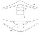
도 1은 착용된 상태에서의 본 발명의 일 실시예에 따른 플랩이 구비된 마스크의 사시도이고, 도 2는 본 발명의 일 실시예에 따른 플랩이 구비된 마스크의 정면도이고, 도 3은 본 발명의 일 실시예에 따른 플랩이 구비된 마스크의 내부 구성을 도시한 것이다.1 is a perspective view of a mask with a flap according to an embodiment of the present invention in a worn state, FIG. 2 is a front view of a mask with a flap according to an embodiment of the present invention, and FIG. 3 is a present invention It shows the internal configuration of the mask provided with a flap according to an embodiment of the.
도 1 내지 도 3을 참조하면, 본 발명의 일 실시예에 따른 플랩이 구비된 마스크(100)는, 사용자의 얼굴 안면에 장착되며 관통구가 형성된 몸체부(110)와, 관통구의 둘레를 따라 설치되는 프레임부(120)와, 프레임부에 개폐가능하도록 설치되는 플랩(130)과, 플랩(130)의 개방도를 제한하는 플랩 개방제한부(150)를 포함한다.1 to 3, the
몸체부(110)는, 장착자의 안면을 감싸며 미세먼지, 황사 등의 외부 대기오염 물질들의 유입을 차단하도록 필터 소재, 일례로 부직포 소재로 형성될 수 있으며 방한이나 스포츠용도 등의 마스크에서는 천으로 제작될 수 있다.The
또한, 몸체부(110)는 장착자의 들숨을 배출할 수 있는 관통구가 정면 중앙부에 위치한다.In addition, the
프레임부(120)는, 몸체부(110)에 형성된 관통구의 둘레에 배치되는 것으로, 상측 프레임부(120)에 플랩(130)의 상측 에지가 부착되어 플랩(130)이 상기 부착부를 중심으로 회전운동하며 개폐되도록 구성된다.The
여기서, 프레임부(120)는 소정 두께를 갖는 강성 재질로 형성될 수 있는데, 이 경우 프레임부(120)가 부착된 몸체부(110)의 관통구 주변 형상을 유지시킬 수 있으며, 또한, 개폐되는 플랩(130)과의 접촉면을 균일하게 유지함으로써 플랩(130) 개폐시의 밀착도가 일정해지도록 한다.Here, the
또한, 프레임부(120)는 몸체부(110)에 형성된 관통구의 형상에 대응되도록 다양한 형상으로 형성될 수 있는데, 본 발명의 일실시예에서는, 하측, 상측, 좌측, 우측에 위치한 4개의 프레임부재(121,123,125,127)의 단부들이 각각 결합된 4각형 프레임으로 구성될 수 있다.In addition, the
플랩(130)은 착용자의 날숨 및 들숨에 따라 몸체부(110)의 관통구를 개폐시키는 기능을 수행하는 구성으로서, 그 형상은 관통구에 대응되도록 형성되며, 들숨시에는 몸체부(110)와 함께 관통구를 폐쇄하며 필터 기능 또한 수행하여야 하기 때문에 필터 소재, 일례로 부직포 소재로 형성될 수 있으며 방한이나 스포츠용도 등의 마스크에서는 천으로 제작될 수 있다.The
여기서, 플랩(130)은 착용자의 얼굴 자세에 따라 중력의 영향을 다르게 받게 되고, 결과적으로 플랩(130)이 개방된 이후 다시 폐쇄시키기 위해 필요한 힘이 달라지게 된다. 이러한 폐쇄력은 착용자의 들숨에 의한 흡입력, 플랩(130)의 탄성력, 한쌍 이상의 자석이 구비될 경우에는 자력 등에 좌우되는 데, 흡입력은 착용자마다 차이가 발생할 수 있다. 특히, 흡입력이 상대적으로 작은 어린이나 여성, 노약자의 경우, 폐쇄력이 상대적으로 작아지게 되어 흡기시의 플랩(130)의 완전한 폐쇄를 위한 수단을 필요로 하게 된다.Here, the
본 발명에서는, 이러한 중력에 의한 영향을 상쇄시키도록 플랩 개방제한부(150)를 포함한다.In the present invention, the flap opening limiting
본 발명의 일 실시예에 의하면, 플랩 개방제한부(150)는, 회전축(151)과, 회전축(151)에서 연장되는 제1부재(153) 및 제2부재(155), 제2부재(155)의 일단에 설치되는 중량체(157)를 포함하여 구성됨으로써 지렛대의 원리에 의해 회전축(151)을 중심으로 서로 다른 방향으로 연장된 제1부재(153) 및 제2부재(155)가 연동되어 작동하도록 구성된다.According to an embodiment of the present invention, the flap opening limiting
회전축(151)은 프레임부(120)에 회전가능하도록 설치되는데, 도 2 및 도 3에 도시된 바와 같이 좌측 프레임부재(125)와 우측 프레임부재(127)을 모두 관통하여 설치될 수 있다. 이 경우, 회전축(151)이 보다 안정적으로 설치될 수 있다. 그러나, 본 발명은 이에 한정되지 아니하고 좌측 프레임부재(125) 또는 우측 프레임부재(127) 중 적어도 하나를 관통하여 설치될 수도 있다. 즉, 도 2 및 도 3의 예에서 좌측 프레임부재(125)만 관통하여 회전축(151)이 설치될 수 있으며, 도 2 및 도 3의 예에서 좌우가 반전되어 제2부재(155) 및 중량체(157)가 우측에 설치되는 경우에는 우측 프레임부재(127)만 관통하여 회전축(151)이 설치될 수 있다.The rotating
또한, 회전축(151)은 전술된 바와 같이 프레임부(120)의 일측을 관통하여 설치될 수 있지만, 이에 한정되지는 않는다. 일례로 일측 프레임부재를 감싸는 방식으로 회전축(151)이 설치될 수도 있고, 프레임부(120) 근처의 몸체부(110)를 관통하여 설치될 수도 있으며, 또다른 실시예로서는 플랩(130) 상부에 덮개형태의 플랩보호부(미도시)를 설치하고 본 플랩보호부(미도시)와 프레임부(120)의 접합부분에 회전축(151)이 수용될 수 있는 안착홈(미도시)을 각각 형성하고 서로 결합하여 구멍 형태의 안착부(미도시)를 구성함으로써 프레임부(120)를 관통하지 않으며 안착부(미도시)에 걸치는 형식으로 회전축(151)이 설치될 수도 있다. 이 경우, 회전축(151)을 설치하기 위한 프레임부(120) 관통 가공작업을 생략할 수 있어 생산공정을 보다 단순화할 수 있는 효과가 있다. 또 다른 실시예로서, 플랩보호부(미도시) 내측에 회전축(250)을 설치할 수도 있다.In addition, the
제1부재(153)는 플랩(130)의 최대 개방도를 제한하도록 프레임부(120)의 외측에 위치한 회전축(151)의 일단에서 절곡되어 플랩(130)의 외측면 위를 가로지르며 연장 형성된다.The
여기서, 제1부재(153)은 회전축(151)의 회전 각도에 연동되어 플랩(130)간의 이격거리가 달라질 수 있도록 회전축(151)과 나란한 방향으로 연장되는 것이 바람직하다. 제1부재(153)의 길이는 플랩(130)의 폭보다 같거나 길게 형성되어 플랩(130)의 개방도를 충분하게 제한할 수 있도록 구성할 수 있다.Here, the
제1부재(153)의 위치에 따라 플랩(130)의 최대 개방도가 달라지게 되는 데, 최대 개방도에 비례하여 플랩(130)을 폐쇄시키기 위한 힘 또한 커지기 때문에 이들을 고려하여 적절한 높이에 제1부재(153)를 위치시켜야 한다. 본 발명의 일 실시예에서 제1부재(153)는, 플랩(130)의 외측면 측에 위치하며 적어도 플랩(130)의 세로 길이의 1/2보다 상측 높이에 위치함으로써 지렛대의 원리가 효과적으로 작용하며 날숨시 플랩(130)이 충분히 개방되면서도 들숨시 플랩(130) 차단을 원활하게 할 수 있도록 한다.The maximum opening degree of the
제2부재(155)는, 회전축(151)의 일단에서 절곡되어 하방으로 연장되어 형성되고, 제2부재(155)의 하측단에는 중량체(157)가 설치된다. 중량체(157)는 착용자의 얼굴을 숙이는 각도에 따라 중력에 의해 이동되고, 이동된 중량체(157)의 위치에 따라 회전축(151)에 연결된 제1부재(153)가 이동하게 되며, 결과적으로 제1부재(153)와 플랩(130)의 외측면(폐쇄 위치에서) 사이의 이격거리가 달라지게 된다.The
도 4는 얼굴을 든 자세에서의 날숨 시 본 발명의 일 실시예에 따른 플랩이 구비된 마스크의 측면도이고, 도 5는 얼굴을 숙인 자세에서의 들숨 시 본 발명의 일 실시예에 따른 플랩이 구비된 마스크의 측면도이다.4 is a side view of a mask with a flap according to an embodiment of the present invention when exhaling in a posture with a face, and FIG. 5 is provided with a flap according to an embodiment of the present invention when exhaling in a posture with a face down Is a side view of the mask.
얼굴을 든 자세에서는 도 4에 도시된 바와 같이, 중량체(157)가 프레임부(120)에 대해 최소각으로 근접하게 되고, 이에 따라 플랩(130)의 개방각(θ1)이 최대가 되고, 제1부재(153)와 프레임부(120)에 밀착된 위치(폐쇄위치)에서의 플랩(130)의 외측면 사이의 이격거리는 최대가 된다. 얼굴을 든 자세에서는 플랩(130)이 중력에 의한 폐쇄력 약화가 크지 않기 때문에 플랩(130)이 최대로 개방되어 착용자의 날숨을 최대로 배출할 수 있게 된다.In the posture with the face, as shown in FIG. 4, the
한편, 얼굴을 숙인 자세에서는 도 5에 도시된 바와 같이, 중량체(157)가 프레임부(120)에 대해 최대각으로 이격되고, 이에 따라 플랩(130)의 개방각(θ2)이 최소가 되고, 제1부재(153)와 프레임부(120)에 밀착된 위치(폐쇄위치)에서의 플랩(130)의 외측면 사이의 이격거리는 최소가 된다. 얼굴을 숙인 자세에서는 플랩(130)이 중력에 의한 폐쇄력 약화가 가장 크기 때문에 플랩(130)의 개방을 최대한 제한하여 착용자가 들숨을 호흡할 때 플랩(130)이 완전하게 폐쇄상태를 유지할 수 있도록 한다.On the other hand, in the face-down posture, as shown in FIG. 5, the
이와 같이 본 발명의 일 실시예에 따른 제1부재(153)와 제2부재(155)는, 중량체(157)가 회전축(151)을 중심으로 회전되며 얼굴의 자세에 따라 중력에 의한 폐쇄력 간섭을 상쇄시킬 수 있는 각도로 회전축(151)을 중심으로 서로 결합된다.As described above, in the
한편, 도 1 내지 도 6에 도시되지는 않았지만, 본 발명의 일 실시예에 따른 플랩이 구비된 마스크(100)는, 프레임부(120)에 적어도 하나의 제1자석(미도시)이 설치되고, 플랩(130)의 내측면에는 제1자석(미도시)과 대응되는 위치에 제2자석(미도시)이 설치되어 폐쇄력을 향상시킬 수도 있다.Meanwhile, although not illustrated in FIGS. 1 to 6, the
도 6은 본 발명의 일 실시예에 따른 플랩이 구비된 마스크의 배면도이다.6 is a rear view of a mask provided with a flap according to an embodiment of the present invention.
도 6을 참조하면, 본 발명의 일 실시예에 따른 플랩이 구비된 마스크(100)는 몸체부(110)의 중앙에 관통구가 구비되어 있으며, 몸체부(110) 내측면에는 관통구의 상측 및 하측으로 연장되는 지지부(160)가 설치될 수 있다. 또한, 지지부(160)는 도 6에서와 같이 상하가 관통구를 통과하여 구성할 수도 있고 상측 프레임부재(123)와 하측 프레임부재(121)에 지지부(160)의 상하부가 각각 나누어 배치됨으로써 지지부(160)가 관통구에 걸치지 않게 구성할 수도 있다.Referring to Figure 6, the
지지부(160)는 플랩이 구비된 마스크(100)의 측면 윤곽을 일정하게 유지하여 외적 미관을 향상시킬 뿐만 아니라, 착용자의 코 및 입 부위가 몸체부(110)의 내측면과 이격되는 공간을 확보하여 적절한 호흡공간을 마련함으로써 보다 편안한 착용감을 느낄 수 있도록 한다.The
또한, 일 실시예로서, 본 발명의 몸체부(110)에는, 착용자의 얼굴면이 접하는 내측면 하부에 수분 흡수부재(170)가 설치될 수 있다. 수분 흡수부재(170)는 착용자가 쾌적한 착용상태를 계속 느낄 수 있도록 몸체부(110) 내측면과 외측면 사이의 온도 차가 크거나 급격한 호흡운동 등에 의해 몸체부(110) 내측면에 응축되는 습기를 흡수하는 기능을 한다.In addition, as an embodiment, the
여기서, 수분 흡수부재(170)의 설치위치는 몸체부(110) 내측면 내에서 응축된 습기가 모일 수 있는 곳에 설치하는 것이 바람직하다. 도 6의 실시예에서는 관통구 하측에 위치한 절곡 라인 상에 설치하여 코 또는 입을 통한 들숨/날숨에 의해 발생되는 습기를 효과적으로 제거할 수 있게 된다.Here, the installation position of the
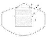
도 7은 사용자가 착용한 상태에서의 본 발명의 다른 실시예에 따른 플랩이 구비된 마스크의 사시도이고, 도 8은 본 발명의 다른 실시예에 따른 플랩이 구비된 마스크의 정면도이다. 이하, 본 발명의 다른 실시예에 대해 도면을 참조하여 설명한다. 일 실시예와 동일한 도면부호를 가지는 구성은 동일한 기능을 하는 동일한 구성으로, 그 설명을 생략하고 차별되는 구성을 중심으로 설명한다.7 is a perspective view of a mask with a flap according to another embodiment of the present invention in a state worn by a user, and FIG. 8 is a front view of a mask with a flap according to another embodiment of the present invention. Hereinafter, another embodiment of the present invention will be described with reference to the drawings. A configuration having the same reference numerals as an embodiment is the same configuration having the same function, and the description thereof will be omitted and the configuration will be mainly described.
본 실시예에 따른 플랩이 구비된 마스크(200)는, 관통부의 개폐가 가능하도록 상측 프레임부(120)에 플랩(130)의 상부 에지가 결합되고, 플랩(130)의 개방도를 제한하도록 플랩(130)의 외측면 위에 가로방향으로 연장되며 이격 설치되는 플랩 개방제한부(250)를 포함한다. 본 실시예에서는 특히 플랩(130)의 소재가 유연하여 날숨 시 플랩 개방제한부(250)를 축으로 플랩(130)의 하단부가 크게 휘어짐으로써 날숨 시 최대 개방도를 얻을 수 있도록 하는 경우를 목적으로 한다.The
플랩 개방제한부(250)는, 선형 부재로 구성되며 양 끝단이 각각 프레임부(120) 또는 인접한 몸체부(110)에 설치될 수 있는데, 일례로, 플랩 개방제한부(250)의 양 끝단이 각각 좌측 프레임부재와 우측 프레임부재를 관통하여 설치될 수 있으며, 또한, 인접 몸체부(110)를 관통하여 설치될 수도 있다.The flap
또 다른 실시예로서는 플랩(130) 상부에 플랩(130)을 보호하기 위한 덮개형태의 플랩보호부(미도시)를 프레임부(120)에 부착하되 플랩보호부(미도시) 내측에는 선형부재 형태의 플랩 개방제한부(250)를 설치하여 이것이 플랩(130)의 상부에 위치하게 함으로써 같은 효과를 얻을 수도 있다. 이 경우, 제조방식의 일실시예로서 사출방식을 사용할 수 있다. 즉, 플랩 개방제한부(250)가 금형의 사출공간 내에에 플랩보호부(미도시)와 함께 사출성형됨으로써 간단하며 견고하게 플랩 개방제한부(250)를 플랩보호부(미도시)에 고정 설치할 수 있게 된다.As another embodiment, a flap protection part (not shown) in the form of a cover for protecting the
또한, 플랩 개방제한부(250)는 양 끝단이 전술된 방식으로 설치되고 끝단부에서 절곡되어 플랩(130)의 외측면에 가로방향으로 나란하게 이격 배치됨으로써 도 7 및 도 8의 도면에서 플랩(130)이 개폐되는 상하방향에 수직하게 위치된다. 이와 같이 배치됨으로써 개방되는 플랩(130)의 이동을 제한하게 된다.In addition, the flap
여기서, 플랩(130)의 외측면과 맞닿는 플랩 개방제한부(250)와, 폐쇄위치에서의 플랩(130) 외측면 간의 이격거리는 얼굴을 숙인 자세에서의 중력에 의한 폐쇄력의 약화에도 플랩(130)이 들숨시에 원활히 폐쇄될 수 있도록 결정되어야 한다. 통상 도 4에 나타낸 바와 같이 플랩 개방제한부(150)를 두어 플랩(130)의 개방도를 중력에 따라 능동 제어하는 방식과 달리 본 도 7 및 도 8에 제시된 실시예에서는 그 이격거리를 더욱 작게 결정하는 것이 바람직하다. 그 대신 날숨 시에 플랩(130)이 충분한 개방도를 얻을 수 있게 플랩(130)을 특히 유연한 재질로 구성하여 플랩 개방제한부(250)를 축으로 플랩(130) 하단부가 외부 방향으로 크게 휘어지게 함으로써 중력에 따른 플랩(130)의 영향을 제어하면서도 들숨 및 날숨 호흡이 원활하게 하는 것이다.Here, the distance between the flap
이를 위해 플랩 개방제한부(250)는, 적어도 플랩(130)의 세로 길이의 1/2보다 상측 높이에 위치하여 플랩(130)을 통한 날숨의 배출이 원활하도록 하며, 플랩(130)의 유연한 탄성에 의해 날숨 시 휘어짐과 들숨 시 복원력이 원활히 동작하도록 구성할 수 있다.To this end, the flap
또한, 도 7에 도시된 바와 같이, 프레임부(120)에는 적어도 하나의 제1자석(121)이 설치되고, 플랩의 내측면에는 제1자석(121)과 대응되는 위치에 제2자석(131)이 설치되어 머리가 하방으로 향하여 플랩(130)이 중력의 영향을 받을 때 좀 더 쉽게 플랩(130)이 폐쇄될 수 있도록 구성할 수 있다.In addition, as shown in FIG. 7, at least one
한편, 본 발명의 실시예들에 따른 플랩이 구비된 마스크(100,200)에서, 중량체(157)를 제외한 플랩 개방제한부(150,250)는, 가공성이 우수하고 견고하며 내구성을 갖춘 선형부재로 구성하는 것이 바람직하다.On the other hand, in the mask (100,200) provided with a flap according to embodiments of the present invention, the flap
전술된 바와 같이, 본 발명의 실시예들에 따른 플랩이 구비된 마스크(100,200)는, 착용자의 얼굴 자세에 따라 중력의 영향에 의해 폐쇄력이 약화되는 것을 방지하도록 중력의 영향을 보상시킬 수 있는 플랩 개방제한부(150,250)를 구비함으로써 착용자의 머리 자세에 관계없이 흡기시에 안정적으로 플랩(130)이 폐쇄될 수 있도록 한다.As described above, the
이상의 설명은 본 발명의 기술 사상을 예시적으로 설명한 것에 불과한 것으로서, 본 발명이 속하는 기술 분야에서 통상의 지식을 가진 자라면 본 발명의 본질적인 특성에서 벗어나지 않는 범위 내에서 다양한 수정, 변경 및 치환이 가능할 것이다. 따라서, 본 발명에 개시된 실시예 및 첨부된 도면들은 본 발명의 기술 사상을 한정하기 위한 것이 아니라 설명하기 위한 것이고, 이러한 실시예 및 첨부된 도면에 의하여 본 발명의 기술 사상의 범위가 한정되는 것은 아니다. 본 발명의 보호 범위는 아래의 청구범위에 의하여 해석되어야 하며, 그와 동등한 범위 내에 있는 모든 기술 사상은 본 발명의 권리범위에 포함되는 것으로 해석되어야 할 것이다.The above description is merely illustrative of the technical idea of the present invention, and those of ordinary skill in the art to which the present invention pertains can make various modifications, changes, and substitutions without departing from the essential characteristics of the present invention. will be. Therefore, the embodiments disclosed in the present invention and the accompanying drawings are not intended to limit the technical spirit of the present invention, but to explain the scope of the technical spirit of the present invention. . The scope of protection of the present invention should be interpreted by the claims below, and all technical spirits within the scope equivalent thereto should be interpreted as being included in the scope of the present invention.
100,200: 플랩이 구비된 마스크
110: 몸체부
120: 프레임부
121: 제1자석
130: 플랩
131: 제2자석
150,250: 플랩 개방제한부
157: 중량체100,200: mask with flap
110: body
120: frame
121: first magnet
130: flap
131: 2nd magnet
150,250: Flap opening limit
157: heavy body
Claims (14)
Translated fromKorean관통구의 둘레를 따라 설치되는 프레임부;
개폐가 가능하도록 상측 프레임부에 상부 에지가 결합되고, 필터로 형성되는 플랩; 및
프레임부에 설치되는 회전축과, 플랩의 개방도를 제한하도록 프레임부의 외측에 위치한 회전축의 일단에서 절곡되어 플랩의 외측면 위를 가로지르며 회전축 방향으로 연장되는 제1부재와, 회전축의 일단에서 절곡되어 하방으로 연장되는 제2부재와, 제2부재의 하측단에 설치되는 중량체를 포함하는 플랩 개방제한부;를 포함하는, 플랩이 구비된 마스크.
One side is formed through the through-hole, the body portion formed by a filter;
A frame portion installed along the periphery of the through hole;
The upper edge is coupled to the upper frame portion to open and close, a flap formed by a filter; And
A rotating shaft installed in the frame portion, a first member that is bent at one end of the rotating shaft located outside the frame portion to limit the opening degree of the flap, and crosses over the outer surface of the flap and extends in the direction of the rotating shaft, and is bent at one end of the rotating shaft A mask provided with a flap, including; a second member extending downward and a flap opening limiting part including a weight body installed at a lower end of the second member.
착용자가 얼굴을 숙이는 각도에 따라 중력에 의해 중량체가 이동되고,
이동된 중량체의 위치에 따라 제1부재와 폐쇄위치의 플랩의 외측면 사이의 이격거리가 달라지도록 구성되는, 플랩이 구비된 마스크.
The method according to claim 1,
The weight is moved by gravity depending on the angle at which the wearer faces down,
A mask provided with a flap, which is configured to vary a separation distance between the first member and the outer surface of the flap in the closed position according to the position of the moved weight.
중량체가 회전축을 중심으로 회전되어 프레임부에 대해 최대각으로 이격될 경우에 최소 이격거리가 되고, 중량체가 프레임부에 대해 최소각으로 근접할 경우에 최대 이격거리가 되도록 제1부재와 제2부재가 결합되는, 플랩이 구비된 마스크.
The method according to claim 2,
The first member and the second member so that the weight is rotated about the rotational axis to be spaced at a maximum angle relative to the frame portion, and the maximum distance is obtained when the weight body is close to the frame portion at a minimum angle. The mask is provided with a flap.
프레임부는,
상측, 하측, 좌측, 우측에 위치한 4개의 프레임부재의 단부들이 각각 결합되어 4각형으로 구성되는, 플랩이 구비된 마스크.
The method according to claim 1,
The frame part,
A mask with a flap, which is composed of a quadrangular shape by combining ends of four frame members located on the upper, lower, left, and right sides.
회전축은 좌측 또는 우측 프레임부재 중 적어도 하나를 관통하거나 걸쳐서 설치되는, 플랩이 구비된 마스크.
The method according to claim 4,
The rotating shaft is a mask with a flap, which is installed through or across at least one of the left or right frame members.
플랩의 외측면 측에 위치한 제1부재는,
적어도 플랩의 세로 길이의 1/2보다 상측 높이에 위치하는, 플랩이 구비된 마스크.
The method according to claim 1,
The first member located on the outer side of the flap,
A mask with a flap, which is located at a height higher than at least half the length of the flap.
몸체부 내측면에 관통구의 상측 및 하측으로 연장되어 설치되는 지지부를 더 포함하는, 플랩이 구비된 마스크.
The method according to claim 1,
A mask provided with a flap, further comprising a support portion extending upward and downward to the through hole on the inner surface of the body portion.
몸체부는,
착용자의 얼굴면이 접하는 내측면 하부에는 수분 흡수부재가 설치되는, 플랩이 구비된 마스크.
The method according to any one of claims 1 to 7,
The body part,
A mask provided with a flap, on which a moisture absorbing member is installed, at the bottom of the inner surface of the wearer's face.
프레임부에는 적어도 하나의 제1자석이 설치되고,
플랩의 내측면에는 제1자석과 대응되는 위치에 제2자석이 설치되는, 플랩이 구비된 마스크.
The method according to claim 4,
At least one first magnet is installed in the frame part,
A mask provided with a flap, on which the second magnet is installed at a position corresponding to the first magnet on the inner surface of the flap.
관통구의 둘레를 따라 설치되는 프레임부;
개폐가 가능하도록 상측 프레임부에 상부 에지가 결합되고, 필터로 형성되는 플랩; 및
플랩의 개방도를 제한하도록 플랩의 외측면 위에 가로방향으로 연장되며 이격 설치되는 플랩 개방제한부;를 포함하되,
플랩 개방제한부는 양 끝단이 각각 프레임부에 연결되거나,
플랩 상부에 플랩보호부를 더 구비하고, 플랩보호부 내측에는 선형부재 형태의 플랩 개방제한부의 양 끝단이 연결되어 플랩의 상부에 위치되는, 플랩이 구비된 마스크.
One side is formed through the through-hole, the body portion formed by a filter;
A frame portion installed along the periphery of the through hole;
The upper edge is coupled to the upper frame portion to open and close, a flap formed by a filter; And
Includes a flap opening limiting portion extending horizontally over the outer surface of the flap and spaced apart to limit the opening degree of the flap.
The flap opening limit is connected to the frame ends at each end, or
A mask with a flap, which is further provided with a flap protection part on the top of the flap, and located at the top of the flap by connecting both ends of the flap opening restriction part in the form of a linear member inside the flap protection part.
플랩 개방제한부는,
적어도 플랩의 세로 길이의 1/2보다 상측 높이에 위치하는, 플랩이 구비된 마스크.
The method according to claim 10,
Flap opening limit,
A mask with a flap, which is located at a height higher than at least half the length of the flap.
프레임부에는 적어도 하나의 제1자석이 설치되고,
플랩의 내측면에는 제1자석과 대응되는 위치에 제2자석이 설치되는, 플랩이 구비된 마스크.The method according to claim 10,
At least one first magnet is installed in the frame part,
A mask provided with a flap, on which the second magnet is installed at a position corresponding to the first magnet on the inner surface of the flap.
Priority Applications (2)
| Application Number | Priority Date | Filing Date | Title |
|---|---|---|---|
| KR1020200002290AKR102106987B1 (en) | 2020-01-07 | 2020-01-07 | Mask having a flap |
| PCT/KR2021/000058WO2021141344A1 (en) | 2020-01-07 | 2021-01-05 | Mask provided with flap |
Applications Claiming Priority (1)
| Application Number | Priority Date | Filing Date | Title |
|---|---|---|---|
| KR1020200002290AKR102106987B1 (en) | 2020-01-07 | 2020-01-07 | Mask having a flap |
Publications (1)
| Publication Number | Publication Date |
|---|---|
| KR102106987B1true KR102106987B1 (en) | 2020-05-06 |
Family
ID=70737445
Family Applications (1)
| Application Number | Title | Priority Date | Filing Date |
|---|---|---|---|
| KR1020200002290AActiveKR102106987B1 (en) | 2020-01-07 | 2020-01-07 | Mask having a flap |
Country Status (1)
| Country | Link |
|---|---|
| KR (1) | KR102106987B1 (en) |
Cited By (5)
| Publication number | Priority date | Publication date | Assignee | Title |
|---|---|---|---|---|
| KR102185275B1 (en)* | 2020-06-18 | 2020-12-01 | 윤흥수 | Mask Tube |
| WO2021141344A1 (en)* | 2020-01-07 | 2021-07-15 | 박종석 | Mask provided with flap |
| KR20220063000A (en) | 2020-11-09 | 2022-05-17 | 배재대학교 산학협력단 | Mask having a plurality of piece elements |
| KR20220131030A (en) | 2021-03-19 | 2022-09-27 | 함세웅 | Accessories for masks that provide a fragrance function |
| KR20220160731A (en) | 2021-05-28 | 2022-12-06 | 윤흥수 | Mask Tube |
Citations (8)
| Publication number | Priority date | Publication date | Assignee | Title |
|---|---|---|---|---|
| KR100258519B1 (en)* | 1992-05-29 | 2000-06-15 | 스프레이그 로버트 월터 | One-way fluid valve and filtered face mask |
| JP2001309990A (en)* | 2000-04-28 | 2001-11-06 | Koken Ltd | mask |
| KR20020082927A (en)* | 2001-04-24 | 2002-11-01 | 삼성전자 주식회사 | Face mask for using in clean room |
| KR20150100286A (en)* | 2014-02-25 | 2015-09-02 | 김병욱 | Mask for exercise |
| KR20170105866A (en)* | 2016-03-10 | 2017-09-20 | 박예진 | Mask |
| KR101953127B1 (en)* | 2018-09-11 | 2019-03-05 | 비클시스템주식회사 | Facial mask |
| KR102035719B1 (en) | 2019-05-22 | 2019-10-23 | 박종석 | A mask having an open filter |
| KR102059923B1 (en)* | 2019-03-19 | 2019-12-27 | 박종석 | A mask having an open filter |
- 2020
- 2020-01-07KRKR1020200002290Apatent/KR102106987B1/enactiveActive
Patent Citations (8)
| Publication number | Priority date | Publication date | Assignee | Title |
|---|---|---|---|---|
| KR100258519B1 (en)* | 1992-05-29 | 2000-06-15 | 스프레이그 로버트 월터 | One-way fluid valve and filtered face mask |
| JP2001309990A (en)* | 2000-04-28 | 2001-11-06 | Koken Ltd | mask |
| KR20020082927A (en)* | 2001-04-24 | 2002-11-01 | 삼성전자 주식회사 | Face mask for using in clean room |
| KR20150100286A (en)* | 2014-02-25 | 2015-09-02 | 김병욱 | Mask for exercise |
| KR20170105866A (en)* | 2016-03-10 | 2017-09-20 | 박예진 | Mask |
| KR101953127B1 (en)* | 2018-09-11 | 2019-03-05 | 비클시스템주식회사 | Facial mask |
| KR102059923B1 (en)* | 2019-03-19 | 2019-12-27 | 박종석 | A mask having an open filter |
| KR102035719B1 (en) | 2019-05-22 | 2019-10-23 | 박종석 | A mask having an open filter |
Cited By (6)
| Publication number | Priority date | Publication date | Assignee | Title |
|---|---|---|---|---|
| WO2021141344A1 (en)* | 2020-01-07 | 2021-07-15 | 박종석 | Mask provided with flap |
| KR102185275B1 (en)* | 2020-06-18 | 2020-12-01 | 윤흥수 | Mask Tube |
| KR20220063000A (en) | 2020-11-09 | 2022-05-17 | 배재대학교 산학협력단 | Mask having a plurality of piece elements |
| KR20220131030A (en) | 2021-03-19 | 2022-09-27 | 함세웅 | Accessories for masks that provide a fragrance function |
| KR20220160731A (en) | 2021-05-28 | 2022-12-06 | 윤흥수 | Mask Tube |
| KR102565309B1 (en)* | 2021-05-28 | 2023-08-08 | 윤흥수 | Mask Tube |
Similar Documents
| Publication | Publication Date | Title |
|---|---|---|
| KR102106987B1 (en) | Mask having a flap | |
| EP3456388B1 (en) | Mask | |
| JP3097085U (en) | mask | |
| US20210352976A1 (en) | Face mask | |
| US20130014316A1 (en) | Detachable facemask frame and facemask for a goggle | |
| EP1529453B1 (en) | Facemask structure improvement | |
| KR200488024Y1 (en) | Facial mask with nostril cover of vented structure | |
| KR20200000600U (en) | A mask having a fixed part that can be used in combination with moisture control frame, fine dust filtering fabric and outside skin fabric | |
| KR101083435B1 (en) | Anti-fog mask | |
| KR20170105866A (en) | Mask | |
| JP2020139237A (en) | mask | |
| JP2022063398A (en) | mask | |
| KR20210060062A (en) | Nose mask for fine dust | |
| KR101349936B1 (en) | Anti-fog mask | |
| CN205512581U (en) | air purification cap | |
| KR102251956B1 (en) | Respiratory Protection Mask | |
| KR102850169B1 (en) | Clean air pocket type mask | |
| KR20120116552A (en) | Mask | |
| JP3233850U (en) | Inner frame | |
| CN114343263A (en) | Neck cover with adjusting function | |
| KR102667364B1 (en) | Support pad for sanitary mask | |
| KR102444714B1 (en) | cooling pad for mask | |
| KR101672697B1 (en) | Dustproof mask | |
| KR200470709Y1 (en) | A Winter Mask of Easy Breath | |
| KR102670329B1 (en) | Mask guard |
Legal Events
| Date | Code | Title | Description |
|---|---|---|---|
| PA0109 | Patent application | Patent event code:PA01091R01D Comment text:Patent Application Patent event date:20200107 | |
| PA0201 | Request for examination | ||
| PA0302 | Request for accelerated examination | Patent event date:20200109 Patent event code:PA03022R01D Comment text:Request for Accelerated Examination Patent event date:20200107 Patent event code:PA03021R01I Comment text:Patent Application | |
| E902 | Notification of reason for refusal | ||
| PE0902 | Notice of grounds for rejection | Comment text:Notification of reason for refusal Patent event date:20200418 Patent event code:PE09021S01D | |
| E701 | Decision to grant or registration of patent right | ||
| PE0701 | Decision of registration | Patent event code:PE07011S01D Comment text:Decision to Grant Registration Patent event date:20200425 | |
| GRNT | Written decision to grant | ||
| PR0701 | Registration of establishment | Comment text:Registration of Establishment Patent event date:20200427 Patent event code:PR07011E01D | |
| PR1002 | Payment of registration fee | Payment date:20200427 End annual number:3 Start annual number:1 | |
| PG1601 | Publication of registration | ||
| PR1001 | Payment of annual fee | Payment date:20230328 Start annual number:4 End annual number:4 | |
| PR1001 | Payment of annual fee | Payment date:20240429 Start annual number:5 End annual number:5 |