KR102100184B1 - Display apparatus - Google Patents
Display apparatusDownload PDFInfo
- Publication number
- KR102100184B1 KR102100184B1KR1020130017118AKR20130017118AKR102100184B1KR 102100184 B1KR102100184 B1KR 102100184B1KR 1020130017118 AKR1020130017118 AKR 1020130017118AKR 20130017118 AKR20130017118 AKR 20130017118AKR 102100184 B1KR102100184 B1KR 102100184B1
- Authority
- KR
- South Korea
- Prior art keywords
- unit
- display device
- casing
- slider
- photographing
- Prior art date
- Legal status (The legal status is an assumption and is not a legal conclusion. Google has not performed a legal analysis and makes no representation as to the accuracy of the status listed.)
- Active
Links
Images


Classifications
- G—PHYSICS
- G06—COMPUTING OR CALCULATING; COUNTING
- G06F—ELECTRIC DIGITAL DATA PROCESSING
- G06F3/00—Input arrangements for transferring data to be processed into a form capable of being handled by the computer; Output arrangements for transferring data from processing unit to output unit, e.g. interface arrangements
- G06F3/01—Input arrangements or combined input and output arrangements for interaction between user and computer
- G06F3/017—Gesture based interaction, e.g. based on a set of recognized hand gestures
- G—PHYSICS
- G06—COMPUTING OR CALCULATING; COUNTING
- G06F—ELECTRIC DIGITAL DATA PROCESSING
- G06F1/00—Details not covered by groups G06F3/00 - G06F13/00 and G06F21/00
- G06F1/16—Constructional details or arrangements
- G—PHYSICS
- G06—COMPUTING OR CALCULATING; COUNTING
- G06F—ELECTRIC DIGITAL DATA PROCESSING
- G06F1/00—Details not covered by groups G06F3/00 - G06F13/00 and G06F21/00
- G06F1/16—Constructional details or arrangements
- G06F1/1601—Constructional details related to the housing of computer displays, e.g. of CRT monitors, of flat displays
- G06F1/1605—Multimedia displays, e.g. with integrated or attached speakers, cameras, microphones
- H—ELECTRICITY
- H04—ELECTRIC COMMUNICATION TECHNIQUE
- H04N—PICTORIAL COMMUNICATION, e.g. TELEVISION
- H04N21/00—Selective content distribution, e.g. interactive television or video on demand [VOD]
- H04N21/40—Client devices specifically adapted for the reception of or interaction with content, e.g. set-top-box [STB]; Operations thereof
- H04N21/41—Structure of client; Structure of client peripherals
- H04N21/422—Input-only peripherals, i.e. input devices connected to specially adapted client devices, e.g. global positioning system [GPS]
- H04N21/42204—User interfaces specially adapted for controlling a client device through a remote control device; Remote control devices therefor
- H—ELECTRICITY
- H04—ELECTRIC COMMUNICATION TECHNIQUE
- H04N—PICTORIAL COMMUNICATION, e.g. TELEVISION
- H04N21/00—Selective content distribution, e.g. interactive television or video on demand [VOD]
- H04N21/40—Client devices specifically adapted for the reception of or interaction with content, e.g. set-top-box [STB]; Operations thereof
- H04N21/41—Structure of client; Structure of client peripherals
- H04N21/422—Input-only peripherals, i.e. input devices connected to specially adapted client devices, e.g. global positioning system [GPS]
- H04N21/4223—Cameras
- H—ELECTRICITY
- H04—ELECTRIC COMMUNICATION TECHNIQUE
- H04N—PICTORIAL COMMUNICATION, e.g. TELEVISION
- H04N21/00—Selective content distribution, e.g. interactive television or video on demand [VOD]
- H04N21/40—Client devices specifically adapted for the reception of or interaction with content, e.g. set-top-box [STB]; Operations thereof
- H04N21/43—Processing of content or additional data, e.g. demultiplexing additional data from a digital video stream; Elementary client operations, e.g. monitoring of home network or synchronising decoder's clock; Client middleware
- H04N21/442—Monitoring of processes or resources, e.g. detecting the failure of a recording device, monitoring the downstream bandwidth, the number of times a movie has been viewed, the storage space available from the internal hard disk
- H04N21/44213—Monitoring of end-user related data
- H04N21/44218—Detecting physical presence or behaviour of the user, e.g. using sensors to detect if the user is leaving the room or changes his face expression during a TV program
- H—ELECTRICITY
- H04—ELECTRIC COMMUNICATION TECHNIQUE
- H04N—PICTORIAL COMMUNICATION, e.g. TELEVISION
- H04N23/00—Cameras or camera modules comprising electronic image sensors; Control thereof
- H04N23/57—Mechanical or electrical details of cameras or camera modules specially adapted for being embedded in other devices
- H—ELECTRICITY
- H04—ELECTRIC COMMUNICATION TECHNIQUE
- H04N—PICTORIAL COMMUNICATION, e.g. TELEVISION
- H04N5/00—Details of television systems
- H04N5/64—Constructional details of receivers, e.g. cabinets or dust covers
Landscapes
- Engineering & Computer Science (AREA)
- Multimedia (AREA)
- Signal Processing (AREA)
- Theoretical Computer Science (AREA)
- General Engineering & Computer Science (AREA)
- Health & Medical Sciences (AREA)
- Human Computer Interaction (AREA)
- General Health & Medical Sciences (AREA)
- Social Psychology (AREA)
- General Physics & Mathematics (AREA)
- Physics & Mathematics (AREA)
- Computer Networks & Wireless Communication (AREA)
- Databases & Information Systems (AREA)
- Computer Hardware Design (AREA)
- Studio Devices (AREA)
- Devices For Indicating Variable Information By Combining Individual Elements (AREA)
- User Interface Of Digital Computer (AREA)
Abstract
Translated fromKoreanDescription
Translated fromKorean본 발명은 디스플레이 장치에 관한 것으로, 보다 구체적으로는 사용자 인터렉션을 제공하는 디스플레이 장치에 관한 것이다.The present invention relates to a display device, and more particularly, to a display device providing user interaction.
최근 들어 디스플레이 장치는 스마트 인터렉티브 기능의 확대에 따라 사용자 인터렉션을 제공하는 제품들이 등장하고 있다. 사용자 인터렉션이란 사용자의 동작이나 음성 등으로 디스플레이 장치를 제어하는 것을 말한다. 이에 따라, 디스플레이 장치에는 사용자의 동작을 감지하는 촬영 유닛이나 사용자의 음성을 감지하는 음성 감지 유닛 등이 필수적으로 장착된다.2. Description of the Related Art Recently, products that provide user interaction have been introduced in the display device as the smart interactive function is expanded. User interaction refers to controlling a display device by a user's motion or voice. Accordingly, the display device is essentially equipped with a photographing unit that detects a user's motion or a voice sensing unit that senses a user's voice.
촬영 유닛이나 음성 감지 유닛은 종래 디스플레이 장치의 상단에 고정되어 장착되었다. 그러나, 이러한 디스플레이 장치는 상단부가 촬영 유닛이나 음성 감지 유닛으로 인해 항상 돌출되므로 디스플레이 장치의 미관을 해치는 문제가 있다. 또한, 디스플레이 장치는 노출된 촬영 유닛이나 음성 감지 유닛으로 인해 사용자에게 사용자의 일상을 감시하는 느낌을 줄 수 있어 사용자의 불쾌감을 유발할 수 있는 문제가 있다.The photographing unit or the audio sensing unit is fixedly mounted on the top of the conventional display device. However, such a display device has a problem in spoiling the aesthetics of the display device since the upper end always protrudes due to the imaging unit or the voice sensing unit. In addition, the display device has a problem that may cause the user's discomfort because the exposed photographing unit or the voice sensing unit may give the user a feeling of monitoring the user's daily life.
이를 해소하기 위해 촬영 유닛 및 음성 감지 유닛을 사용하지 않을 때에는 촬영 유닛 및 음성 감지 유닛을 사용자에게 보여지지 않도록 디스플레이 장치의 후면 상부에서 상하로 슬라이딩 가능하도록 장착되는 예가 있다. 촬영 유닛을 예로써 설명하면, 촬영 유닛의 촬영시에는 촬영 유닛이 디스플레이 장치의 후면 상부에서 위쪽으로 돌출되며, 촬영 유닛의 비촬영시에는 돌출된 촬영 유닛이 아래로 슬라이딩되어 디스플레이 장치에서 보이지 않게 된다. 이러한 촬영 유닛 및 음성 감지 유닛은 디스플레이 장치의 전면으로부터 디스플레이 장치의 측면 두께만큼 뒤에 위치한다. 따라서, 보다 큰 카메라 화각을 확보하기 위해서는 필연적으로 촬영 유닛이 더 위쪽으로 돌출되는 것이 요구되어 디스플레이 장치의 미관을 해치는 문제가 있다.In order to solve this, there is an example in which the shooting unit and the voice sensing unit are mounted to be slidable up and down at the upper rear of the display device so that the user does not see the shooting unit and the voice sensing unit. If the photographing unit is described as an example, when photographing the photographing unit, the photographing unit protrudes upward from the upper rear of the display device, and when the photographing unit is not photographed, the protruding photographing unit slides down and becomes invisible on the display device. . The photographing unit and the voice sensing unit are located behind the front surface of the display device by the side thickness of the display device. Therefore, in order to secure a larger camera angle of view, it is inevitably required that the photographing unit protrude further upward, and there is a problem that spoils the aesthetics of the display device.
따라서, 본 발명의 목적은 디스플레이 장치의 미관을 해치지 않으면서 보다 큰 카메라 화각을 확보할 수 있는 디스플레이 장치를 제공하는 데 있다.Accordingly, an object of the present invention is to provide a display device capable of securing a larger camera angle of view without compromising the aesthetics of the display device.
상기 목적을 달성하기 위해, 본 발명은, 사용자 인터렉션을 제공하는 디스플레이 장치로서, 영상 표시면을 가진 디스플레이 본체 및 사용자의 제스처 감지를 위해 사용자를 촬영하는 카메라 모듈을 포함하는 촬영 유닛으로서, 비촬영시 상기 디스플레이 본체 내에 수용되는 제1 위치에 배치되고 촬영시 상기 디스플레이 본체 밖으로 돌출되는 제2 위치에 배치되는 촬영 유닛을 포함하며, 상기 카메라 모듈은, 상기 촬영 유닛이 상기 제1 위치에 있을 때보다 상기 제2 위치에 있을 때, 상기 영상 표시면에 더 가깝게 배치되는 것을 특징으로 하는 디스플레이 장치를 제공한다.In order to achieve the above object, the present invention, as a display device for providing a user interaction, a display unit having an image display surface and a camera module for photographing a user for gesture detection by the user, as a shooting unit, when not shooting And a photographing unit disposed in a first position accommodated in the display body and disposed in a second position protruding out of the display body when photographing. It provides a display device, characterized in that disposed in the second position closer to the image display surface.
상기 카메라 모듈은, 상기 촬영 유닛이 상기 제1 위치에 있을 때에는 상기 디스플레이 본체의 상방을 바라보게 배치되며, 상기 촬영 유닛이 상기 제2 위치에 있을 때에는 상기 디스플레이 본체의 전방을 바라보게 배치될 수 있다.The camera module may be arranged to face upwards of the display body when the imaging unit is in the first position, and may be arranged to face the front of the display body when the imaging unit is in the second position. .
상기 촬영 유닛은 곡선 궤적을 따르는 슬라이딩에 의해 상기 제1 위치로부터 상기 제2 위치로 또는 상기 제2 위치로부터 상기 제1 위치로 이동할 수 있다.The photographing unit may move from the first position to the second position or from the second position to the first position by sliding along a curved trajectory.
상기 촬영 유닛은, 상기 곡선 궤적에 대응하는 형상을 가지며 서로 일정 거리 이격된 한 쌍의 슬라이드 가이드홈을 가진 카메라 케이싱을 더 포함하며, 상기 디스플레이 본체는, 디스플레이 패널을 수용하는 메인 케이싱 및 상기 메인 케이싱의 후면에 장착되어 상기 제1 위치에 배치된 촬영 유닛을 수용하며, 상기 카메라 케이싱의 슬라이딩을 안내하도록 상기 한 쌍의 슬라이드 가이드홈에 삽입되는 한 쌍의 가이드돌기를 가진 보조 케이싱을 포함할 수 있다.The photographing unit further includes a camera casing having a shape corresponding to the curved trajectory and having a pair of slide guide grooves spaced apart from each other by a certain distance, and the display body comprises: a main casing accommodating a display panel and the main casing It is mounted on the rear of the housing unit to accommodate the photographing unit disposed in the first position, and may include an auxiliary casing having a pair of guide projections inserted into the pair of slide guide grooves to guide the sliding of the camera casing. .
상기 디스플레이 장치는 상기 제1 위치에 배치된 상기 촬영 유닛을 상기 보조 케이싱 내에 로킹시키기 위한 로킹 유닛을 더 포함할 수 있다.The display device may further include a locking unit for locking the photographing unit disposed in the first position in the auxiliary casing.
상기 로킹 유닛은, 상기 촬영 유닛에 연결된 래치 유닛 및 상기 보조 케이싱에 구비되며, 상기 촬영 유닛이 상기 제1 위치에 배치될 때 상기 래치 유닛과 결합하여 상기 촬영 유닛을 로킹시키는 로킹 부재를 포함할 수 있다.The locking unit is provided in the latch unit and the auxiliary casing connected to the photographing unit, and may include a locking member that locks the photographing unit by engaging the latch unit when the photographing unit is disposed in the first position. have.
상기 래치 유닛은, 래치 하우징 및 상기 래치 하우징 밖으로 노출되는 노출 위치와 상기 래치 하우징 안으로 부분 삽입되는 부분 삽입 위치 사이에서 이동 가능한 한 쌍의 후크 부재를 포함하며, 상기 촬영 유닛이 상기 제2 위치로부터 상기 제1 위치로 이동시, 상기 한 쌍의 후크 부재는 상기 노출 위치로부터 상기 부분 삽입 위치로 이동하면서 상기 로킹 부재를 후킹 결합하고, 상기 촬영 유닛이 상기 제1 위치로부터 상기 제2 위치로 이동시, 상기 한 쌍의 후크 부재는 상기 부분 삽입 위치로부터 상기 노출 위치로 이동하면서 상기 로킹 부재와 분리될 수 있다.The latch unit includes a latch housing and a pair of hook members movable between an exposed position exposed outside the latch housing and a partially inserted position partially inserted into the latch housing, wherein the imaging unit is disposed from the second position. When moving to the first position, the pair of hook members hooks the locking member while moving from the exposed position to the partial insertion position, and when the imaging unit moves from the first position to the second position, the one The pair of hook members can be separated from the locking member while moving from the partially inserted position to the exposed position.
상기 로킹 부재는, 상기 보조 케이싱으로부터 수직 연장된 몸체부 및 상기 몸체부의 선단에 구비되며 상기 한 쌍의 후크 부재와 결합하는 결합부를 포함하며, 상기 한 쌍의 후크 부재는, 상기 노출 위치로부터 상기 부분 삽입 위치로 이동시 상기 결합부와 후킹되도록 탄성적으로 서로 좁혀지며, 상기 부분 삽입 위치로부터 상기 노출 위치로 이동시 상기 결합부와 분리되도록 탄성적으로 서로 이격될 수 있다.The locking member includes a body portion vertically extending from the auxiliary casing, and a coupling portion provided at a tip of the body portion and engaged with the pair of hook members, wherein the pair of hook members comprises the portion from the exposed position. When moving to the insertion position it is elastically narrowed to each other so as to hook with the coupling portion, and may be elastically spaced from each other so as to be separated from the coupling portion when moving from the partial insertion position to the exposure position.
상기 카메라 케이싱은, 상기 카메라 모듈이 장착되며 상기 한 쌍의 슬라이드 가이드홈이 형성된 베이스 케이싱 및 상기 베이스 케이싱을 커버하는 커버 케이싱을 포함할 수 있다.The camera casing may include a base casing on which the camera module is mounted and the pair of slide guide grooves are formed, and a cover casing covering the base casing.
상기 베이스 케이싱은 알루미늄 재질로 형성될 수 있다.The base casing may be formed of aluminum.
상기 디스플레이 장치는 상기 래치 유닛이 장착되며, 상기 촬영 유닛과 결합되는 슬라이더를 더 포함하며, 상기 슬라이더는, 상기 촬영 유닛이 상기 제2 위치로부터 상기 제1 위치로 이동시 하방으로 슬라이딩되어 상기 로킹 부재를 상기 후크 부재와 후킹 결합시키고, 상기 후크 부재와 상기 로킹 부재가 분리되면 상방으로 슬라이딩되어 상기 촬영 유닛을 상기 제1 위치로부터 상기 제2 위치로 이동시킬 수 있다.The display device further includes a slider in which the latch unit is mounted, and coupled to the photographing unit, wherein the slider is slid downward when the photographing unit is moved from the second position to the first position to open the locking member. When the hook member and the hooking member are hooked, and the hook member and the locking member are separated, they can slide upward to move the photographing unit from the first position to the second position.
상기 디스플레이 장치는 상기 슬라이더의 양측에 구비되며 상기 슬라이더의 슬라이딩을 가이드하기 위한 한 쌍의 가이드 레일을 더 포함할 수 있다.The display device is provided on both sides of the slider and may further include a pair of guide rails for guiding the sliding of the slider.
상기 디스플레이 장치는 상기 후크 부재와 상기 로킹 부재의 분리가 분리될 때 상기 슬라이더를 상방으로 가압하는 탄성 부재를 더 포함할 수 있다.The display device may further include an elastic member that presses the slider upward when separation of the hook member and the locking member is separated.
상기 탄성 부재는 토션 바 스프링일 수 있다.The elastic member may be a torsion bar spring.
상기 디스플레이 장치는 상기 슬라이더에 장착되며, 상기 슬라이더의 슬라이딩 속도를 조절하기 위한 댐핑 부재를 더 포함할 수 있다.The display device is mounted on the slider, and may further include a damping member for adjusting the sliding speed of the slider.
상기 댐핑 부재는 회전 댐퍼로 구비되며, 상기 가이드 레일에 구비된 댐퍼 레일에 맞물려 회전할 수 있다.The damping member is provided with a rotating damper, and can be rotated by being engaged with a damper rail provided on the guide rail.
상기 촬영 유닛은 상기 카메라 모듈의 틸트를 조절하기 위한 틸트 레버를 더 포함할 수 있다.The photographing unit may further include a tilt lever for adjusting the tilt of the camera module.
상기 디스플레이 장치는 상기 디스플레이 본체 내부에 장착되며 상기 사용자의 음성을 감지하기 위한 적어도 하나의 음성 감지 유닛을 더 포함할 수 있다.The display device is mounted inside the display body and may further include at least one voice detection unit for detecting the user's voice.
상기 적어도 하나의 음성 감지 유닛은 상기 디스플레이 본체의 상면에 인접하게 장착되며 상기 촬영 유닛의 양측에 하나씩 마련될 수 있다.The at least one voice sensing unit is mounted adjacent to an upper surface of the display body and may be provided one on each side of the photographing unit.
상기 디스플레이 장치는 텔레비젼일 수 있다.The display device may be a television.
이상과 같은 본 발명의 다양한 실시예들에 따라, 사용자 인터렉션을 제공하는 디스플레이 장치에서 디스플레이 장치의 미관을 해치지 않으면서 보다 큰 카메라 화각을 확보하는 디스플레이 장치를 제공할 수 있다.According to various embodiments of the present invention as described above, it is possible to provide a display device that secures a larger camera angle without compromising the aesthetics of the display device in a display device that provides user interaction.
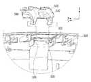
도 1 및 도 2는 본 발명의 일 실시예에 따른 디스플레이 장치를 도시한 사시도이다.
도 3은 촬영 유닛이 제1 위치에 배치된 때 도 1의 디스플레이 장치에 구비되는 모습을 도시한 단면도이다.
도 4는 촬영 유닛이 제2 위치에 배치된 때 도 2의 디스플레이 장치에 구비되는 모습을 도시한 개략적인 단면도이다.
도 5는 도 1의 디스플레이 장치의 보조 케이싱을 도시한 사시도이다.
도 6은 도 5의 보조 케이싱을 도시한 분해 사시도이다.
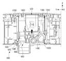
도 7은 도 5의 보조 케이싱의 내부를 도시한 도면이다.
도 8은 도 5의 보조 케이싱에 구비되는 촬영 유닛을 도시한 분해 단면도이다.
도 9는 도 5의 보조 케이싱 및 촬영 유닛의 베이스 케이싱의 결합 관계를 도시한 분해 사시도이다.
도 10은 도 5의 보조 케이싱 내에 구비되는 촬영 유닛 및 슬라이더의 결합 관계를 도시한 분해 사시도이다.
도 11은 촬영 유닛이 제2 위치에서 제1 위치로 슬라이딩할 때 촬영 유닛의 슬라이딩 동작을 설명하기 위한 도면이다.
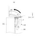
도 12는 촬영 유닛이 제2 위치에서 제1 위치로 슬라이딩할 때 촬영 유닛의 이동 궤적을 설명하기 위한 도면이다.
도 13은 촬영 유닛의 로킹을 설명하기 위한 도면이다.
도 14는 촬영 유닛이 제1 위치에서 제2 위치로 슬라이딩할 때 촬영 유닛의 슬라이딩 동작을 설명하기 위한 도면이다.
도 15는 촬영 유닛의 로킹 해제를 설명하기 위한 도면이다.
도 16은 촬영 유닛이 제1 위치에서 제2 위치로 슬라이딩할 때 촬영 유닛의 이동 궤적을 설명하기 위한 도면이다.1 and 2 are perspective views illustrating a display device according to an exemplary embodiment of the present invention.
3 is a cross-sectional view showing a state provided in the display device of FIG. 1 when the imaging unit is disposed in the first position.
4 is a schematic cross-sectional view showing a state provided in the display device of FIG. 2 when the imaging unit is disposed in the second position.
5 is a perspective view illustrating an auxiliary casing of the display device of FIG. 1.
FIG. 6 is an exploded perspective view showing the auxiliary casing of FIG. 5.
7 is a view showing the interior of the auxiliary casing of FIG. 5.
8 is an exploded cross-sectional view showing an imaging unit provided in the auxiliary casing of FIG. 5.
9 is an exploded perspective view showing a coupling relationship between the auxiliary casing of FIG. 5 and the base casing of the imaging unit.
10 is an exploded perspective view showing a coupling relationship between a shooting unit and a slider provided in the auxiliary casing of FIG. 5.
11 is a view for explaining a sliding operation of the imaging unit when the imaging unit slides from the second position to the first position.
12 is a view for explaining the movement trajectory of the imaging unit when the imaging unit slides from the second position to the first position.
13 is a view for explaining the locking of the imaging unit.
14 is a view for explaining a sliding operation of the imaging unit when the imaging unit slides from the first position to the second position.
15 is a view for explaining unlocking of the imaging unit.
16 is a view for explaining the movement trajectory of the imaging unit when the imaging unit slides from the first position to the second position.
본 발명은 첨부된 도면을 참조하여 본 발명의 바람직한 실시예를 상세히 설명함으로써 더욱 명백해 질 것이다. 여기서 설명되는 실시예는 발명의 이해를 돕기 위하여 예시적으로 나타낸 것이며, 본 발명은 여기서 설명되는 실시예와 다르게 다양하게 변형되어 실시될 수 있음이 이해되어야 할 것이다. 또한, 발명의 이해를 돕기 위하여, 첨부된 도면은 실제 축척대로 도시된 것이 아니라 일부 구성요소의 치수가 과장되게 도시될 수 있다.The present invention will become more apparent by describing the preferred embodiments of the present invention in detail with reference to the accompanying drawings. It should be understood that the embodiments described herein are illustratively shown to help understanding of the present invention, and that the present invention can be implemented in various ways differently from the embodiments described herein. In addition, in order to help the understanding of the invention, the accompanying drawings are not drawn to scale, but the dimensions of some components may be exaggerated.
도 1 및 도 2는 본 발명의 일 실시예에 따른 디스플레이 장치를 도시한 사시도이며, 도 3은 촬영 유닛이 제1 위치에 배치된 때 도 1의 디스플레이 장치에 구비되는 모습을 도시한 단면도이며, 도 4는 촬영 유닛이 제2 위치에 배치된 때 도 2의 디스플레이 장치에 구비되는 모습을 도시한 개략적인 단면도이며, 도 5는 도 1의 디스플레이 장치의 보조 케이싱을 도시한 사시도이며, 도 6은 도 5의 보조 케이싱을 도시한 분해 사시도이다.1 and 2 are perspective views showing a display device according to an exemplary embodiment of the present invention, and FIG. 3 is a cross-sectional view showing a state provided in the display device of FIG. 1 when the imaging unit is disposed in a first position, FIG. 4 is a schematic cross-sectional view showing a state provided in the display device of FIG. 2 when the imaging unit is disposed in the second position, FIG. 5 is a perspective view showing the auxiliary casing of the display device of FIG. 1, and FIG. 6 is It is an exploded perspective view showing the auxiliary casing of FIG. 5.
도 1 및 도 2를 참조하면, 디스플레이 장치(100)는 사용자 인터렉션을 통해 다양한 사용자의 제스처나 음성 등을 감지하여 이에 따른 다양한 제어 동작을 수행할 수 있다. 제어 동작은 예를 들어, 채널의 변경, 볼륨 업이나 다운, 어플리케이션의 실행 등이 될 수 있다.1 and 2, the
디스플레이 장치(100)는 평판 디스플레이로서, LCD 텔레비젼, LED 텔레비젼이나 OLED 텔레비젼이 될 수 있다. 이외에도, 디스플레이 장치(100)는 다른 방식의 평판 디스플레이가 될 수도 있고, 평판 디스플레이가 아닌 곡면 디스플레이, 또는 플렉서블 디스플레이가 될 수도 있다. 또한, 디스플레이 장치는 텔레비젼이 아닌 컴퓨터 모니터가 될 수도 있다.The
이러한 디스플레이 장치(100)는 디스플레이 본체(120) 및 촬영 유닛(500)을 포함한다.The
디스플레이 장치(100)는 사용자 인터렉션을 통해 다양한 사용자의 제스처나 음성 등을 감지하여 이에 따른 다양한 제어 동작을 수행할 수 있다. 제어 동작은 예를 들어, 채널의 변경, 볼륨 업이나 다운, 어플리케이션의 실행 등이 될 수 있다.The
디스플레이 장치(100)는 평판 디스플레이로서, LCD 텔레비젼, LED 텔레비젼이나 OLED 텔레비젼이 될 수 있다. 이외에도, 디스플레이 장치(100)는 다른 방식의 평판 디스플레이가 될 수도 있고, 평판 디스플레이가 아닌 곡면 디스플레이, 또는 플렉서블 디스플레이가 될 수도 있다.The
디스플레이 본체(120)는 메인 케이싱(200), 디스플레이 패널(미도시), 제어 보드(미도시), 파워 보드(미도시), 및 보조 케이싱(300)을 포함한다.The
메인 케이싱(200)은 디스플레이 패널(미도시), 제어 보드(미도시) 및 파워 보드(미도시) 등 디스플레이 장치(100)의 각종 부품들을 수용한다.The
디스플레이 패널은 영상을 표시하는 부품으로서, 영상이 표시되는 영상 표시면(220)을 갖는다. 사용자는 영상 표시면(220)을 통해 디스플레이 장치(100)가 제공하는 다양한 컨텐츠들을 시청할 수 있다.The display panel is a component that displays an image, and has an
제어 보드는 디스플레이 장치(100)의 동작을 제어하기 위한 것으로, 사용자 인터렉션에 따른 코맨드에 따라 디스플레이 장치(100)의 동작을 제어할 수도 있다. 파워 보드는 디스플레이 장치(100)에 전압을 공급하기 위한 것이다.The control board is for controlling the operation of the
보조 케이싱(300)은 전술한 메인 케이싱(200)의 후면 상부에 장착되며, 촬영 유닛(500)을 수용한다. 본 실시예에서는 보조 케이싱(300)이 메인 케이싱(200)의 후면에 따로 장착되는데, 보조 케이싱(300)이 메인 케이싱(200)과 일체로 형성되는 것도 가능하다.The
도 5 및 도 6을 참조하면, 보조 케이싱(300)은 전면 케이싱(320) 및 후면 케이싱(340)을 포함한다.5 and 6, the
전면 케이싱(320)은 디스플레이 장치(100)의 메인 케이싱(200)의 후면 상부에 결합된다. 전면 케이싱(320)은 상면(321)에 촬영 유닛(500)이 통과되는 개구(322)를 갖는다. 이러한 개구(322)를 통해 촬영 유닛(500)은 보조 케이싱(300) 밖으로 돌출되거나 보조 케이싱(300) 안으로 수용된다.The
후면 케이싱(340)은 전면 케이싱(320)과 결합되어 보조 케이싱(300)의 후면을 형성한다. 전면 케이싱(320)과 후면 케이싱(340) 사이의 공간에 촬영 유닛(500), 음성 감지 유닛(400) 등 디스플레이 장치(100)의 사용자 인터렉션을 위한 각종 부품들이 수용된다.The
촬영 유닛(500)은 사용자의 제스처 감지를 위한 것으로, 슬라이딩 가능하게 보조 케이싱(300)에 장착된다. 비촬영시 촬영 유닛(500)은 보조 케이싱(300) 내부에 수용되어 메인 케이싱(200)의 상면(202) 높이를 넘지 않게 배치된다. 촬영 유닛(500)은 보조 케이싱(300) 내부에 수용시 보호창(502)이 메인 케이싱(200)의 상면(202)과 동일 높이에 배치된다.The photographing
도 3 내지 도 6을 참조하면, 촬영 유닛(500)은 카메라 케이싱(510), 카메라 모듈(600) 및 틸트 레버(580)를 포함한다.3 to 6, the
카메라 케이싱(510)은 베이스 케이싱(520) 및 커버 케이싱(560)을 포함한다.The
베이스 케이싱(520)은 내부에 카메라 모듈(600) 및 틸트 레버(580)가 장착되며 전면에 보호창(502)이 장착된다. 베이스 케이싱(520)은 카메라 모듈(600)에서 발생하는 열을 방열하기 위해 알루미늄 재질로 이루어질 수 있다.The
커버 케이싱(560)은 베이스 케이싱(520)과 결합되며 촬영 유닛(500)의 외관을 형성한다. 도 6에 도시된 바와 같이 커버 케이싱(560)에는 보호창(502)이 끼워지는 전면 개구(562) 및 틸트 레버(560)를 노출시키는 틸트 레버 개구(564)가 형성된다. 한편, 커버 케이싱(560)은 베이스 케이싱(520)과 달리 플라스틱 재질로 이루어질 수 있다.The
카메라 모듈(600)은 촬영 유닛(500) 내에 구비되며, 사용자의 제스처를 감지하기 위한 구성요소이다. 촬영 유닛(600)은 이러한 카메라 모듈(600)을 내장함에 따라 사용자의 제스처를 감지할 수 있다. 카메라 모듈(600)은 영상의 빛을 모아주는 적어도 하나의 렌즈(미도시), 영상을 전기적 신호로 변환하는 이미지 센서(미도시) 및 렌즈를 움직여 포커스를 조절하는 액추에이터(미도시) 등을 포함한다.The
도 1 및 도 3에 도시된 바와 같이, 비촬영시 촬영 유닛(500)은 비촬영시 보조 케이싱(300) 내부에 수용되는 제1 위치에 배치된다. 촬영 유닛(500)은 영상 표시면(220)으로부터 메인 케이싱(200)의 두께(d)만큼 이격되어 배치된다. 즉, 이때, 촬영 유닛(500)과 영상 표시면(220) 사이의 거리(d)는 메인 케이싱(200)의 두께(d)와 실질적으로 동일하다. 이때, 카메라 모듈(600)은 위쪽 방향(+Z 방향)을 향하도록 배치된다. 이를 통해, 비촬영시 촬영 유닛(500)은 디스플레이 장치(100)의 전면에서 보았을 때 보이지 않게 보관될 수 있다. 따라서, 촬영 유닛(500)에 의해 느낄 수 있는 사용자의 불편함을 해소할 수 있다. 또한, 비촬영시 디스플레이 장치(100)의 외관을 깔끔히 할 수 있어, 제품의 고급화 이미지를 도모할 수 있다.1 and 3, the
도 2 및 도 4에 도시된 바와 같이, 사용자 촬영시 촬영 유닛(500)은 보조 케이싱(300) 밖으로 돌출되는 제2 위치에 배치된다. 촬영 유닛(500)은 디스플레이 장치(100)의 전방(+X 방향)으로 돌출되어 메인 케이싱(200)의 상면(202) 위에 배치된다. 이때, 촬영 유닛(500)은 영상 표시면(220)까지 소정 거리(d') 이격되어 배치되며, 촬영 유닛(500)의 보호창(502)은 영상 표시면(220)보다 약간 뒤에 배치된다. 즉, 촬영 유닛(500)과 영상 표시면(220) 사이의 거리(d')는 메인 케이싱(200)의 두께(d)보다 짧다. 전술한 제1 위치(촬영 유닛(500)이 보조 케이싱(300) 내부에 수용되는 위치)와 비교하면, 촬영 유닛(500)은 제1 위치에 있을 때보다 제2 위치에 있을 때, 영상 표시면(220)에 더 가깝게 배치된다. 따라서, 촬영시 촬영 유닛(500)은 보다 큰 카메라 화각 확보를 위해 디스플레이 장치(100)의 상방(+Z 방향)으로 추가적으로 돌출될 필요가 없다. 따라서, 디스플레이 장치(100)는 디스플레이 장치(100)의 미관을 해치지 않으면서 보다 큰 카메라 화각을 확보할 수 있다.2 and 4, when the user photographs, the photographing
틸트 레버(580)는 카메라의 틸트 조절을 위한 구성요소이다. 틸트란 카메라의 위치는 고정되고 앵글만 위에서 아래로 또는 아래에서 위로 촬영하는 것을 말한다. 틸트 레버(580) 조작에 따라, 카메라 모듈(600)은 촬영 유닛(500) 내에서 Y축 방향을 중심으로 위아래로 회전된다. 틸트 레버(580)는 커버 케이싱(560)의 틸트 레버 개구(564)를 통해 외부로 노출된다. 사용자는 틸트 레버(580)의 조작을 통해 카메라의 틸트를 원하는 만큼 조절할 수 있다.The
도 7은 도 5의 보조 케이싱의 내부를 도시한 도면이다.7 is a view showing the interior of the auxiliary casing of FIG. 5.
도 6 및 도 7을 참조하면, 디스플레이 장치(100)는 음성 감지 유닛(400) 및 피시비 기판(700)을 또한 포함한다.6 and 7, the
음성 감지 유닛(400)은 보조 케이싱(300) 내에 수용될 수 있게 장착되며 보조 케이싱(300) 외부로 노출되지 않는다. 본 실시예에 따른 디스플레이 장치(100) 음성 감지 유닛(400)이 촬영 유닛(500)과 일체형으로 구비되지 않고 별도로 구비되므로, 촬영 유닛(500)에 음성 감지 유닛(400)을 위한 추가 공간이 마련될 필요가 없다. 때문에, 본 실시예에 따른 디스플레이 장치(100)는 외부로 노출되는 촬영 유닛(500)의 부피를 줄일 수 있다.The
음성 감지 유닛(400)은 마이크(420) 및 마이크 홀(450)을 포함한다.The
마이크(420)는 사용자의 음성을 감지하기 위한 구성요소이다. 마이크(420)는 하나 이상 구비될 수 있으며, 본 실시예에의 경우 두 개의 마이크(420)가 구비된다. 두 개의 마이크(420)는 촬영 유닛(500)의 양측에 하나씩 마련되며, 전면 케이싱(320)의 상면(321)과 인접하게 배치된다.The
마이크 홀(450)은 사용자의 음성이 마이크(420)로 전달되는 것을 가이드한다. 본 실시예의 경우 네 개의 마이크 홀(450)이 구비되며, 마이크(420)의 상측에 두 개의 마이크 홀(450)이 구비되며, 다른 두 개의 마이크 홀(450)은 마이크(420)의 후면과 마주하도록 후면 케이싱(340)에 구비된다.The
피시비 기판(700)은 촬영 유닛(500)에 의해 감지된 사용자의 제스처 정보 및 음성 감지 유닛(400)이 감지한 사용자의 음성 정보에 기초하여 사용자 인터렉션을 판단한다. 피시비 기판(700)은 디스플레이 장치(100)의 제어 보드(미도시)로 사용자 인터렉션에 대한 정보를 송신하며, 디스플레이 장치(100)의 제어 보드(미도시)는 사용자 인터렉션에 대한 정보를 기초로 디스플레이 장치(100)를 제어한다.The
한편, 피시비 기판(700)은 촬영 유닛(500)에 의해 감지된 사용자의 제스처 정보 및 음성 감지 유닛(400)이 감지한 사용자의 음성 정보에 기초하여 사용자 인터렉션을 판단하지 않고, 촬영 유닛(500)에 의해 감지된 사용자의 제스처 정보 및 음성 감지 유닛(400)이 감지한 사용자의 음성 정보를 곧바로 디스플레이 장치의 제어 보드로 송신할 수도 있다. 이 경우, 디스플레이 장치(100)의 제어 보드는 수신한 촬영 유닛(500)에 의해 감지된 사용자의 제스처 정보 및 음성 감지 유닛(400)이 감지한 사용자의 음성 정보를 기초로 사용자 인터렉션을 판단한 후 그에 따라 디스플레이 장치를 제어할 수도 있다.On the other hand, the
도 6 및 도 7을 참조하면, 촬영 유닛(500)이 제1 위치(촬영 유닛(500)이 보조 케이싱(300) 내부에 수용되는 위치)와 제2 위치(촬영 유닛(500)이 보조 케이싱(300) 밖으로 돌출되는 위치) 사이에서 이동 가능하도록, 디스플레이 장치(100)는 로킹 유닛(900), 슬라이더(1000), 가이드 레일(1200), 탄성 부재(1400) 및 댐핑 부재(1600)를 또한 포함한다.6 and 7, the photographing
로킹 유닛(900)은 제1 위치에 배치된 촬영 유닛(500)을 보조 케이싱(300) 내에 로킹시키기 위한 구성요소이다. 로킹 유닛(900)은 촬영 유닛(500)이 제2 위치에 배치될 때에는 로킹이 해제된다.The
이러한 로킹 유닛(900)은 래치 유닛(920) 및 로킹 부재(960)를 포함한다.The
래치 유닛(920)은 슬라이더(1000)에 장착되며, 슬라이더(1000)는 촬영 유닛(500)에 결합된다. 따라서, 래치 유닛(920)은 슬라이더(1000)를 통해 촬영 유닛(500)에 연결된다. 래치 유닛(920)은 로킹 부재(960)와 결합되고 로킹 부재(960)와 분리됨으로써, 촬영 유닛(500)의 로킹 및 언로킹을 수행한다.The
이러한 래치 유닛(920)은 래치 하우징(930) 및 후크 부재(940)를 포함한다.The
래치 하우징(930)은 슬라이더(1000)에 장착된다. 래치 하우징(930)에는 로킹 해제시 후크 부재(940)를 래치 하우징(930) 밖으로 밀어내는 스프링(미도시)이 내장되어 있다. 후크 부재(940)는 한 쌍 구비되며, 래치 하우징(930) 밖으로 노출되는 노출 위치와 래치 하우징(930) 안으로 부분 삽입되는 부분 삽입 위치 사이에서 이동 가능하게 래치 하우징(930)에 장착된다.The
로킹 부재(960)는 보조 케이싱(300)의 후면 케이싱(340)에 구비된다. 로킹 부재(960)는 후면 케이싱(340)의 내측 하면으로부터 위쪽 방향(+Z 방향)으로 돌출 형성된다. 로킹 부재(960)는 후면 케이싱(340)에 일체로 형성된다. 이에 한정되는 것은 아니며 로킹 부재는 별도의 부재로 구비되어 후면 케이싱에 장착되는 것도 가능하다.The locking
이러한 로킹 부재(960)는 몸체부(962) 및 결합부(966)를 포함한다.The locking
몸체부(962)는 후면 케이싱(340)으로부터 수직 방향(+Z 방향)으로 연장 형성된다. 결합부(966)는 몸체부(962)의 선단에 구비되며 래치 유닛(920)의 후크 부재(940)와 탈착 가능하게 결합된다.The
로킹 부재(960)는 촬영 유닛(500)이 제1 위치(촬영 유닛(500)이 보조 케이싱(300) 내부에 수용되는 위치)에 배치될 때에는 래치 유닛(920)의 후크 부재(940)과 결합되며, 촬영 유닛(500)이 제2 위치(촬영 유닛(500)이 보조 케이싱(300) 밖으로 돌출되는 위치)에 배치될 때에는 래치 유닛(920)의 후크 부재(940)와 결합이 해제된다.The locking
슬라이더(1000)는 촬영 유닛(500)과 결합되며 보조 케이싱(300) 내에서 상하 방향(Z 방향)으로 슬라이딩 가능하게 장착된다. 가이드 레일(1200)은 슬라이더(100)의 상하 방향(Z 방향) 슬라이딩을 가이드하기 위한 것으로, 슬라이더(100)의 양측에 하나씩 구비된다. 각각의 가이드 레일(1200)에는 슬라이더(100)의 측단부가 삽입되는 가이드 슬릿(1220)이 형성된다.The
탄성 부재(1400)는 촬영 유닛(500)의 로킹이 해제될 때 슬라이더(1000)가 상측 방향(+Z 방향)으로 이동될 수 있는 구동력을 제공하기 위한 구성요소이다. 탄성 부재(1400)의 일단은 슬라이더(1000)에 고정되며 탄성 부재(1400)의 타단은 가이드 레일(1200)에 고정된다. 탄성 부재(1400)는 스프링으로 구비될 수 있으며, 본 실시예에서는 토션 바 스프링(torsion bar spring)으로 구비된다.The
댐핑 부재(1600)는 슬라이더(1000)의 슬라이딩 속도를 조절하기 위한 것이다. 댐핑 부재(1600)는 회전 댐퍼로 구비되며, 가이드 레일(1200)에 구비된 댐퍼 레일(1260)에 맞물리게 장착된다. 댐핑 부재(1600)는 슬라이더(1000)의 슬라이딩시 가이드 레일(1200)의 레일(1260)을 따라 회전됨으로써, 슬라이더(1000)의 슬라이딩 속도를 조절하게 된다. 댐핑 부재(1600)는 슬라이더(1000)에 한 개가 장착된다. 이에 따라, 가이드 레일(1200)의 댐퍼 레일(1260) 또한 댐핑 부재(1600)와 인접한 가이드 레일(1200)에만 구비된다.The damping
이하, 도 8 내지 도 10을 참조하여 촬영 유닛(500)의 이동을 가이드하는 구성에 대해 좀더 자세히 설명한다.Hereinafter, a configuration for guiding the movement of the photographing
도 8은 도 5의 보조 케이싱에 구비되는 촬영 유닛을 도시한 분해 단면도이며, 도 9는 도 5의 보조 케이싱 및 촬영 유닛의 베이스 케이싱의 결합 관계를 도시한 분해 사시도이며, 도 10은 도 5의 보조 케이싱 내에 구비되는 촬영 유닛 및 슬라이더의 결합 관계를 도시한 분해 사시도이다.8 is an exploded cross-sectional view showing an imaging unit provided in the auxiliary casing of FIG. 5, FIG. 9 is an exploded perspective view showing a coupling relationship between the auxiliary casing of FIG. 5 and the base casing of the imaging unit, and FIG. 10 is FIG. 5 It is an exploded perspective view showing a coupling relationship between an imaging unit and a slider provided in the auxiliary casing.
도 8을 참조하면, 촬영 유닛(500)의 베이스 케이싱(520)에는 양측면에 각각 슬라이드 가이드홈(540)이 형성된다. 각각의 슬라이드 가이드홈(540)은 아래 방향(-Z 방향)으로 점차적으로 구부러지는 곡선 형상을 갖는다.Referring to FIG. 8, slide guide
도 9를 참조하면, 전면 케이싱(320)의 개구(320) 아래 부분에는 베이스 케이싱(520)의 한 쌍의 슬라이드 가이드홈(540)에 삽입되는 한 쌍의 가이드돌기(326)가 형성된다. 한 쌍의 가이드돌기(326)는 서로 마주보게 배치된다. 한 쌍의 가이드돌기(326)는 한 쌍의 슬라이드 가이드홈(540)에 삽입되어 촬영 유닛(500)의 이동시 베이스 케이싱(520)의 슬라이딩을 안내한다.Referring to FIG. 9, a pair of
도 10을 참조하면, 커버 케이싱(560)에는 양측단부에 각각 이동돌기(568)가 형성된다. 슬라이더(1000)에는 한 쌍의 이동돌기(568)가 삽입되는 한 쌍의 커버 가이드홈(1020)이 형성된다. 한 쌍의 커버 가이드홈(1020)은 촬영 유닛(500)의 이동시 커버 케이싱(560)의 슬라이딩을 안내한다.Referring to Figure 10, the
이하에서는, 촬영 유닛(500)이 제1 위치(촬영 유닛(500)이 보조 케이싱(300) 내부에 수용되는 위치)와 제2 위치(촬영 유닛(500)이 보조 케이싱(300) 밖으로 돌출되는 위치) 사이에서 슬라이딩할 때의 동작을 구체적으로 설명한다.Hereinafter, the photographing
먼저, 촬영 유닛(500)이 제2 위치에서 제1 위치로 슬라이딩할 때의 동작을 설명한다.First, an operation when the photographing
도 11은 촬영 유닛이 제2 위치에서 제1 위치로 슬라이딩할 때 촬영 유닛의 슬라이딩 동작을 설명하기 위한 도면이며, 도 12는 촬영 유닛이 제2 위치에서 제1 위치로 슬라이딩할 때 촬영 유닛의 이동 궤적을 설명하기 위한 도면이며, 도 13은 촬영 유닛의 로킹을 설명하기 위한 도면이다.11 is a view for explaining a sliding operation of the imaging unit when the imaging unit slides from the second position to the first position, and FIG. 12 shows the movement of the imaging unit when the imaging unit slides from the second position to the first position It is a figure for explaining the trajectory, and FIG. 13 is a figure for explaining the locking of the imaging unit.
도 11을 참조하면, 비촬영시 사용자는 촬영 유닛(500)을 보조 케이싱(300) 내부에 수납할 수 있다. 이를 통해, 디스플레이 장치(100)는 비촬영시 촬영 유닛(500)을 디스플레이 장치(100)의 전면에서 보이지 않도록 보관할 수 있다.Referring to FIG. 11, when not photographing, the user may store the photographing
도 11의 A 부분에 도시된 바와 같이, 사용자는 비촬영시 촬영 유닛(500)의 전면을 가압한다. 촬영 유닛(500)은 사용자의 전면 가압에 따라 아래 방향을 따라 슬라이딩된다.11, the user presses the front surface of the photographing
도 12를 참조하면, 촬영 유닛(500)은 사용자가 전면을 가압하면 곡선 궤적(C)을 따르는 슬라이딩에 의해 제2 위치로부터 제1 위치로 이동하여 보조 케이싱(300) 내부에 수용된다. 여기서, 곡선 궤적(C)은 촬영 유닛(500)의 슬라이드 가이드홈(540)의 형상에 대응한다. 즉, 촬영 유닛(500)은 슬라이드 가이드홈(540)의 형상에 대응하는 곡선 궤적(C)을 그리며 제2 위치로부터 제1 위치로 이동한다.Referring to FIG. 12, when the user presses the front surface, the photographing
이때, 촬영 유닛(500)의 임의의 포인트는 제2 위치에 배치된 상태에서의 위치(P1)에서 제1 위치에 배치된 상태에서의 위치(P2)까지 슬라이드 가이드홈(540)의 형상에 대응하는 곡선 궤적(C)을 따라 이동한다. 촬영 유닛(500)의 다른 포인트들도 이와 같은 방식으로 이동한다.At this time, any point of the photographing
이후, 사용자는 도 11의 B 부분에 도시된 바와 같이 촬영 유닛(500)이 보조 케이싱(300)의 개구(321)의 약간 아래에 눌릴 때까지 촬영 유닛(500)을 더 가압한다. 이는 촬영 유닛(500)의 로킹을 위한 것으로 이에 대해서는 하기 도 13에서 자세히 설명한다.Thereafter, the user further presses the
도 13을 참조하면, 촬영 유닛(500)의 이동시, 촬영 유닛(500)과 결합된 슬라이더(1000)는 보조 케이싱(300) 내에서 아래 방향(-Z 방향)으로 슬라이딩된다. 이때, 댐핑 부재(1600)는 가이드 레일(1200)의 댐퍼 레일(1260)에 맞물려 돌아가면서 슬라이더(1000)가 급격히 아래 방향(-Z 방향)으로 이동되는 것을 방지한다.Referring to FIG. 13, when the
래치 유닛(920)은 슬라이더(100)가 이동할 때, 보조 케이싱(300)의 아래 방향(-Z 방향)으로 이동한다. 이때, 래치 유닛(920)과 로킹 부재(960)가 결합함으로써, 촬영 유닛(500)은 제1 위치에 로킹된다.When the
래치 유닛(920)과 로킹 부재(960)의 결합을 살펴 보면, 래치 유닛(920)은 전술한 보조 케이싱(300)의 아래 방향(-Z 방향)의 이동으로 인해 한 쌍의 후크 부재(940)가 로킹 부재(960)의 결합부(966)와 맞닿는다. 이후, 한 쌍의 후크 부재(940)는 래치 하우징(930) 밖으로 노출되는 노출 위치로부터 래치 하우징(930)으로 안으로 부분 삽입되는 삽입 위치로 이동된다. 이때, 사용자가 촬영 유닛(500)에 대한 가압을 해제하면, 래치 유닛(920) 내부의 스프링으로 인해 슬라이더(1000)는 다시 보조 케이싱(300)의 윗방향(+Z 방향)으로 살짝 이동된다. 이때, 래치 유닛(920)의 한 쌍의 후크 부재(940)는 탄성적으로 서로 좁혀지면서 로킹 부재(960)의 결합부(966)와 후킹 결합된다.Looking at the combination of the
사용자의 전면 가압 해제시, 촬영 유닛(500)은 슬라이더(1000)의 보조 케이싱(300) 윗방향(+Z 방향) 이동으로 인해 도 1에 도시된 바와 같이 보조 케이싱(300)의 상면(321) 높이까지 좀더 올라간다.When the user presses and releases the front pressure, the photographing
한편, 탄성 부재(1400)는 슬라이더(1000)의 아래 방향(-Z 방향)으로의 이동시 아래 방향(-Z 방향)으로 늘어나 슬라이더(1000)의 윗방향(+Z 방향)으로 되돌아가려는 탄성 가압력이 생긴다. 이러한 탄성 가압력은 촬영 유닛(500)의 로킹이 해제될 때 슬라이더(1000)를 윗방향(+Z 방향)으로 이동될 수 있게 한다.Meanwhile, when the
다음으로, 촬영 유닛(500)이 제1 위치에서 제2 위치로 슬라이딩할 때의 동작을 설명한다.Next, an operation when the photographing
도 14는 촬영 유닛이 제1 위치에서 제2 위치로 슬라이딩할 때 촬영 유닛의 슬라이딩 동작을 설명하기 위한 도면이며, 도 15는 촬영 유닛의 로킹 해제를 설명하기 위한 도면이며, 도 16은 촬영 유닛이 제1 위치에서 제2 위치로 슬라이딩할 때 촬영 유닛의 이동 궤적을 설명하기 위한 도면이다.14 is a view for explaining the sliding operation of the shooting unit when the shooting unit slides from the first position to the second position, FIG. 15 is a view for explaining unlocking of the shooting unit, and FIG. 16 is for the shooting unit It is a view for explaining the movement trajectory of the imaging unit when sliding from the first position to the second position.
도 14를 참조하면, 사용자는 촬영 유닛(500)의 촬영시에는 디스플레이 장치(100) 밖으로 돌출시킬 수 있다. 이를 통해, 디스플레이 장치(100)는 촬영 유닛(500)을 통해 디스플레이 장치(100)의 전방에 위치한 사용자의 제스처를 감지할 수 있다.Referring to FIG. 14, a user may protrude out of the
도 14의 A 부분에 도시된 바와 같이, 사용자는 촬영시 촬영 유닛(500)이 보조 케이싱(300)의 개구(321)의 약간 아래에 눌릴 때까지 촬영 유닛(500)의 전면을 가압한다. 이는 촬영 유닛(500)의 로킹 해제를 위한 것으로 이에 대해서는 하기 도 15에서 자세히 설명한다.As shown in part A of FIG. 14, the user presses the front surface of the photographing
도 15를 참조하면, 촬영 유닛(500)이 보조 케이싱(300)의 개구(321)의 약간 아래로 눌려지면, 슬라이더(1000)는 보조 케이싱(300)의 아래 방향(-Z 방향)으로 살짝 이동된다. 이때, 래치 유닛(920)의 한 쌍의 후크 부재(940)는 내부 스프링으로 인해 래치 하우징(930) 밖으로 노출되는 노출 위치로 밀려난다. 한 쌍의 후크 부재(940)는 래치 하우징(930) 밖으로 노출되면 탄성적으로 서로 이격되어 로킹 부재(960)의 결합부(966)와 분리된다. 이를 통해 촬영 유닛(500)은 보조 케이싱(300) 내에서 로킹이 해제된다.15, when the photographing
촬영 유닛(500)의 로킹이 해제되면, 탄성 부재(1400)는 슬라이더(1000)가 보조 케이싱(300)의 윗방향(+Z 방향)으로 이동될 수 있게 보조 케이싱(300)의 윗방향(+Z 방향)으로 탄성 가압력을 제공한다. 슬라이더(1000)는 탄성 부재(1400)가 제공하는 탄성 가압력으로 인해 보조 케이싱(300)의 윗방향(+Z 방향)으로 슬라이딩된다. 이때, 댐핑 부재(1600)는 가이드 레일(1200)의 레일(1260)에 맞물려 돌아가면서 슬라이더(1000)가 급격히 윗방향(+Z 방향)으로 이동되는 것을 방지한다. 슬라이더(1000)가 윗방향(+Z 방향)으로 슬라이딩될 때, 촬영 유닛(500)도 함께 슬라이딩되어 보조 케이싱(300) 밖으로 돌출된다. 이러한 촬영 유닛(500)의 슬라이딩에 대해서는 하기 도 16에서 자세히 설명한다.When the locking of the photographing
도 16을 참조하면, 촬영 유닛(500)은 곡선 궤적(C)을 따르는 슬라이딩에 의해 제1 위치로부터 제2 위치로 이동하여 보조 케이싱(300) 밖으로 돌출된다. 여기서, 곡선 궤적(C)은 앞선 도 12에서 살펴 본 바와 같이 촬영 유닛(500)의 슬라이드 가이드홈(540)의 형상에 대응한다. 즉, 촬영 유닛(500)은 슬라이드 가이드홈(540)의 형상에 대응하는 곡선 궤적(C)을 그리며 제1 위치로부터 제2 위치로 이동한다.Referring to FIG. 16, the
이때, 촬영 유닛(500)의 임의의 포인트는 제1 위치에 배치된 상태에서의 위치(P2)에서 제2 위치에 배치된 상태에서의 위치(P1)까지 슬라이드 가이드홈(540)의 형상에 대응하는 곡선 궤적(C)을 따라 이동한다. 촬영 유닛(500)의 다른 포인트들도 이와 같은 방식으로 이동한다.At this time, any point of the photographing
이상에서는 본 발명의 바람직한 실시예에 대하여 도시하고 설명하였지만, 본 발명은 상술한 특정의 실시예에 한정되지 아니하며, 청구범위에서 청구하는 본 발명의 요지를 벗어남이 없이 당해 발명이 속하는 기술분야에서 통상의 지식을 가진자에 의해 다양한 변형실시가 가능한 것은 물론이고, 이러한 변형실시들은 본 발명의 기술적 사상이나 전망으로부터 개별적으로 이해돼서는 안 될 것이다.In the above, preferred embodiments of the present invention have been illustrated and described, but the present invention is not limited to the specific embodiments described above, and it is usually in the technical field to which the present invention belongs without departing from the gist of the present invention claimed in the claims. Of course, various modifications can be made by those having knowledge of, and these modifications should not be individually understood from the technical idea or prospect of the present invention.
100: 디스플레이 장치120: 디스플레이 본체
200: 메인 케이싱220: 영상 표시면
300: 보조 케이싱400: 음성 감지 유닛
500: 촬영 유닛600: 카메라 모듈100: display device 120: display body
200: main casing 220: video display surface
300: auxiliary casing 400: voice detection unit
500: shooting unit 600: camera module
Claims (24)
Translated fromKorean비촬영시 상기 디스플레이 본체 내부에 수용되는 제1 위치에 배치되고 촬영시 상기 디스플레이 본체 밖으로 돌출되는 제2 위치에 배치되는 카메라 모듈;
상기 제1 위치와 상기 제2 위치 사이에서 상기 카메라 모듈의 이동 속도를 조정하기 위해 구비된 댐핑 부재; 및
상기 카메라 모듈을 상기 제1 위치로부터 상기 제2 위치로 이동시키기 위해 위쪽 방향으로 슬라이딩 이동하고, 상기 카메라 모듈을 상기 제2 위치로부터 상기 제1 위치로 이동시키기 위해 아래쪽 방향으로 슬라이딩 이동하도록 구비된 슬라이더를 포함하고,
상기 댐핑 부재는 상기 슬라이더의 슬라이딩 속도를 조정하기 위해 배열되는 디스플레이 장치.A display body having an image display surface;
A camera module disposed at a first position accommodated inside the display body when not photographing and disposed at a second location protruding out of the display body when photographing;
A damping member provided to adjust the movement speed of the camera module between the first position and the second position; And
A slider provided to slide the camera module upwards to move from the first position to the second position, and a slider provided to slide downwards to move the camera module from the second position to the first position Including,
The damping member is a display device arranged to adjust the sliding speed of the slider.
사용자의 제스처 감지를 위해 사용자를 촬영하는 상기 카메라 모듈을 포함하는 촬영 유닛을 포함하고,
상기 카메라 모듈은,
상기 촬영 유닛이 상기 제1 위치에 있을 때보다 상기 제2 위치에 있을 때, 상기 영상 표시면에 더 가깝게 배치되고, 상기 제1 위치에 있을 때에는 상기 디스플레이 본체의 상방을 바라보게 배치되며, 상기 촬영 유닛이 상기 제2 위치에 있을 때에는 상기 디스플레이 본체의 전방을 바라보게 배치되는 디스플레이 장치.According to claim 1,
And a photographing unit including the camera module for photographing a user to detect a user's gesture,
The camera module,
When the photographing unit is in the second position than when in the first position, it is disposed closer to the image display surface, and when in the first position, it is arranged to face upwards of the display body, and the photographing A display device arranged to face the front of the display body when the unit is in the second position.
상기 촬영 유닛은 곡선 궤적을 따르는 슬라이딩에 의해 상기 제1 위치로부터 상기 제2 위치로 또는 상기 제2 위치로부터 상기 제1 위치로 이동하는 것을 특징으로 하는 디스플레이 장치.According to claim 2,
The photographing unit moves the display from the first position to the second position or from the second position to the first position by sliding along a curved trajectory.
상기 촬영 유닛은,
상기 곡선 궤적에 대응하는 형상을 가지며 서로 일정 거리 이격된 한 쌍의 슬라이드 가이드홈을 가진 카메라 케이싱;을 더 포함하며,
상기 디스플레이 본체는,
디스플레이 패널을 수용하는 메인 케이싱; 및
상기 메인 케이싱의 후면에 장착되어 상기 제1 위치에 배치된 촬영 유닛을 수용하며, 상기 카메라 케이싱의 슬라이딩을 안내하도록 상기 한 쌍의 슬라이드 가이드홈에 삽입되는 한 쌍의 가이드돌기를 가진 보조 케이싱;을 포함하는 것을 특징으로 하는 디스플레이 장치.According to claim 3,
The shooting unit,
It further includes a camera casing having a shape corresponding to the curved trajectory and having a pair of slide guide grooves spaced apart from each other by a certain distance,
The display body,
A main casing accommodating the display panel; And
An auxiliary casing mounted on the rear side of the main casing to accommodate the photographing unit disposed in the first position, and having a pair of guide projections inserted into the pair of slide guide grooves to guide sliding of the camera casing; Display device comprising a.
상기 제1 위치에 배치된 상기 촬영 유닛을 상기 보조 케이싱 내에 로킹시키기 위한 로킹 유닛;을 더 포함하는 것을 특징으로 하는 디스플레이 장치.According to claim 4,
And a locking unit for locking the photographing unit disposed in the first position in the auxiliary casing.
상기 로킹 유닛은,
상기 촬영 유닛에 연결된 래치 유닛; 및
상기 보조 케이싱에 구비되며, 상기 촬영 유닛이 상기 제1 위치에 배치될 때 상기 래치 유닛과 결합하여 상기 촬영 유닛을 로킹시키는 로킹 부재;를 포함하는 것을 특징으로 하는 디스플레이 장치.The method of claim 5,
The locking unit,
A latch unit connected to the photographing unit; And
And a locking member provided in the auxiliary casing and locking the imaging unit in combination with the latch unit when the imaging unit is disposed in the first position.
상기 래치 유닛은,
래치 하우징; 및
상기 래치 하우징 밖으로 노출되는 노출 위치와 상기 래치 하우징 안으로 부분 삽입되는 부분 삽입 위치 사이에서 이동 가능한 한 쌍의 후크 부재;를 포함하며,
상기 촬영 유닛이 상기 제2 위치로부터 상기 제1 위치로 이동시, 상기 한 쌍의 후크 부재는 상기 노출 위치로부터 상기 부분 삽입 위치로 이동하면서 상기 로킹 부재를 후킹 결합하고,
상기 촬영 유닛이 상기 제1 위치로부터 상기 제2 위치로 이동시, 상기 한 쌍의 후크 부재는 상기 부분 삽입 위치로부터 상기 노출 위치로 이동하면서 상기 로킹 부재와 분리되는 것을 특징으로 하는 디스플레이 장치.The method of claim 6,
The latch unit,
Latch housing; And
And a pair of hook members movable between an exposed position exposed outside the latch housing and a partially inserted position partially inserted into the latch housing.
When the photographing unit moves from the second position to the first position, the pair of hook members hook the locking member while moving from the exposed position to the partial insertion position,
When the photographing unit is moved from the first position to the second position, the pair of hook members are separated from the locking member while moving from the partial insertion position to the exposed position.
상기 로킹 부재는,
상기 보조 케이싱으로부터 수직 연장된 몸체부; 및
상기 몸체부의 선단에 구비되며 상기 한 쌍의 후크 부재와 결합하는 결합부;를 포함하며,
상기 한 쌍의 후크 부재는, 상기 노출 위치로부터 상기 부분 삽입 위치로 이동시 상기 결합부와 후킹되도록 탄성적으로 서로 좁혀지며, 상기 부분 삽입 위치로부터 상기 노출 위치로 이동시 상기 결합부와 분리되도록 탄성적으로 서로 이격되는 것을 특징으로 하는 디스플레이 장치.The method of claim 7,
The locking member,
A body portion vertically extended from the auxiliary casing; And
It is provided on the front end of the body portion and the engaging portion coupled to the pair of hook members; includes,
The pair of hook members are elastically narrowed to each other so as to hook with the engaging portion when moving from the exposed position to the partially inserted position, and elastically separated from the engaging portion when moving from the partially inserted position to the exposed position Display device, characterized in that spaced apart from each other.
상기 카메라 케이싱은,
상기 카메라 모듈이 장착되며 상기 한 쌍의 슬라이드 가이드홈이 형성된 베이스 케이싱; 및
상기 베이스 케이싱을 커버하는 커버 케이싱;을 포함하는 것을 특징으로 하는 디스플레이 장치.According to claim 4,
The camera casing,
A base casing on which the camera module is mounted and the pair of slide guide grooves are formed; And
And a cover casing covering the base casing.
상기 베이스 케이싱은 알루미늄 재질로 형성되는 것을 특징으로 하는 디스플레이 장치.The method of claim 9,
The base casing is a display device characterized in that it is formed of an aluminum material.
상기 래치 유닛이 장착되며, 상기 촬영 유닛과 결합되는 슬라이더;를 더 포함하며,
상기 슬라이더는, 상기 촬영 유닛이 상기 제2 위치로부터 상기 제1 위치로 이동시 하방으로 슬라이딩되어 상기 로킹 부재를 상기 후크 부재와 후킹 결합시키고, 상기 후크 부재와 상기 로킹 부재가 분리되면 상방으로 슬라이딩되어 상기 촬영 유닛을 상기 제1 위치로부터 상기 제2 위치로 이동시키는 것을 특징으로 하는 디스플레이 장치.The method of claim 7,
The latch unit is mounted, a slider coupled to the photographing unit; further includes,
The slider is slid downward when the photographing unit moves from the second position to the first position to hook the locking member with the hook member, and when the hook member and the locking member are separated, the slider slides upward. A display device characterized by moving the imaging unit from the first position to the second position.
상기 슬라이더의 양측에 구비되며 상기 슬라이더의 슬라이딩을 가이드하기 위한 한 쌍의 가이드 레일;을 더 포함하는 것을 특징으로 하는 디스플레이 장치.The method of claim 11,
And a pair of guide rails provided on both sides of the slider to guide sliding of the slider.
상기 후크 부재와 상기 로킹 부재의 분리가 분리될 때 상기 슬라이더를 상방으로 가압하는 탄성 부재;를 더 포함하는 것을 특징으로 하는 디스플레이 장치.The method of claim 12,
And an elastic member for urging the slider upward when separation of the hook member and the locking member is separated.
상기 탄성 부재는 토션 바 스프링인 것을 특징으로 하는 디스플레이 장치.The method of claim 13,
The elastic member is a display device, characterized in that the torsion bar spring.
상기 댐핑 부재는 상기 슬라이더에 장착되며, 상기 슬라이더의 슬라이딩 속도를 조절하는 디스플레이 장치.The method of claim 12,
The damping member is mounted on the slider, a display device for adjusting the sliding speed of the slider.
상기 댐핑 부재는 회전 댐퍼로 구비되며, 상기 가이드 레일에 구비된 댐퍼 레일에 맞물려 회전하는 것을 특징으로 하는 디스플레이 장치.The method of claim 15,
The damping member is provided with a rotating damper, the display device characterized in that it rotates in engagement with the damper rail provided on the guide rail.
상기 촬영 유닛은 상기 카메라 모듈의 틸트를 조절하기 위한 틸트 레버;를 더 포함하는 것을 특징으로 하는 디스플레이 장치.According to claim 2,
The photographing unit further comprises a tilt lever for adjusting the tilt of the camera module.
상기 디스플레이 본체 내부에 장착되며 상기 사용자의 음성을 감지하기 위한 적어도 하나의 음성 감지 유닛;을 더 포함하는 것을 특징으로 하는 디스플레이 장치.According to claim 2,
And at least one voice sensing unit mounted inside the display body to sense the user's voice.
상기 적어도 하나의 음성 감지 유닛은 상기 디스플레이 본체의 상면에 인접하게 장착되며 상기 촬영 유닛의 양측에 하나씩 마련되는 것을 특징으로 하는 디스플레이 장치.The method of claim 18,
The at least one voice detection unit is mounted adjacent to the upper surface of the display body, characterized in that the display device is provided on each side of the shooting unit.
상기 디스플레이 장치는 텔레비젼인 것을 특징으로 하는 디스플레이 장치.The method according to any one of claims 1 to 19,
The display device is a display device, characterized in that the television.
상기 슬라이더의 슬라이딩 이동을 가이드하도록 배열된 가이드 레일을 더 포함하는 디스플레이 장치.According to claim 1,
And a guide rail arranged to guide the sliding movement of the slider.
상기 댐핑 부재는 상기 슬라이더 상에 마련되는 디스플레이 장치.The method of claim 22,
The damping member is a display device provided on the slider.
상기 가이드 레일 상에 마련된 댐퍼 레일을 더 포함하고,
상기 댐핑 부재는 상기 댐퍼 레일에 결합되도록 장착되는 디스플레이 장치.
The method of claim 22 or 23,
Further comprising a damper rail provided on the guide rail,
The damping member is a display device mounted to be coupled to the damper rail.
Priority Applications (11)
| Application Number | Priority Date | Filing Date | Title |
|---|---|---|---|
| KR1020130017118AKR102100184B1 (en) | 2013-02-18 | 2013-02-18 | Display apparatus |
| PCT/KR2013/011513WO2014126330A1 (en) | 2013-02-18 | 2013-12-12 | Display apparatus |
| BR112015016419-6ABR112015016419B1 (en) | 2013-02-18 | 2013-12-12 | DISPLAY DEVICE THAT PROVIDES USER INTERACTIONS |
| MX2015010624AMX345939B (en) | 2013-02-18 | 2013-12-12 | Display apparatus. |
| US14/135,786US9529441B2 (en) | 2013-02-18 | 2013-12-20 | Display apparatus |
| EP19166156.0AEP3525454B1 (en) | 2013-02-18 | 2014-01-23 | Display apparatus |
| EP21171705.3AEP3879818A1 (en) | 2013-02-18 | 2014-01-23 | Display appratus |
| EP14152348.0AEP2768219B1 (en) | 2013-02-18 | 2014-01-23 | Display apparatus |
| JP2014024113AJP6362346B2 (en) | 2013-02-18 | 2014-02-12 | Display device |
| CN201910207475.0ACN109996103B (en) | 2013-02-18 | 2014-02-17 | Display device |
| CN201410053004.6ACN103997667B (en) | 2013-02-18 | 2014-02-17 | display screen |
Applications Claiming Priority (1)
| Application Number | Priority Date | Filing Date | Title |
|---|---|---|---|
| KR1020130017118AKR102100184B1 (en) | 2013-02-18 | 2013-02-18 | Display apparatus |
Publications (2)
| Publication Number | Publication Date |
|---|---|
| KR20140103578A KR20140103578A (en) | 2014-08-27 |
| KR102100184B1true KR102100184B1 (en) | 2020-04-13 |
Family
ID=50097539
Family Applications (1)
| Application Number | Title | Priority Date | Filing Date |
|---|---|---|---|
| KR1020130017118AActiveKR102100184B1 (en) | 2013-02-18 | 2013-02-18 | Display apparatus |
Country Status (8)
| Country | Link |
|---|---|
| US (1) | US9529441B2 (en) |
| EP (3) | EP3525454B1 (en) |
| JP (1) | JP6362346B2 (en) |
| KR (1) | KR102100184B1 (en) |
| CN (2) | CN109996103B (en) |
| BR (1) | BR112015016419B1 (en) |
| MX (1) | MX345939B (en) |
| WO (1) | WO2014126330A1 (en) |
Families Citing this family (13)
| Publication number | Priority date | Publication date | Assignee | Title |
|---|---|---|---|---|
| KR102040288B1 (en) | 2013-02-27 | 2019-11-04 | 삼성전자주식회사 | Display apparatus |
| USD735156S1 (en)* | 2013-05-22 | 2015-07-28 | Lg Electronics Inc. | Television receiver |
| USD735155S1 (en)* | 2013-05-22 | 2015-07-28 | Lg Electronics Inc. | Television receiver |
| KR20150102489A (en)* | 2014-02-28 | 2015-09-07 | 삼성전자주식회사 | Display apparatus |
| JP2016144195A (en)* | 2015-02-05 | 2016-08-08 | Necパーソナルコンピュータ株式会社 | Information processing device |
| JP6773971B2 (en)* | 2016-09-20 | 2020-10-21 | 富士通クライアントコンピューティング株式会社 | Display device |
| CN107197133B (en) | 2017-07-21 | 2019-11-29 | 维沃移动通信有限公司 | A kind of mobile terminal and CCD camera assembly |
| CN209105221U (en)* | 2018-09-07 | 2019-07-12 | Oppo广东移动通信有限公司 | mobile terminal |
| DE112018007831T5 (en) | 2018-11-01 | 2021-04-08 | Lg Electronics Inc. | DISPLAY DEVICE |
| TWI734329B (en) | 2019-12-31 | 2021-07-21 | 技嘉科技股份有限公司 | Electronic device and trigger method of key macro using external input signal |
| CN210781088U (en)* | 2020-01-15 | 2020-06-16 | 赣州市牧士电子有限公司 | Comprehensive screen of television |
| CN111511143A (en)* | 2020-05-18 | 2020-08-07 | 北京小米移动软件有限公司 | Integrated module and display device |
| CN116045174B (en)* | 2021-10-28 | 2025-07-25 | 纬联电子科技(中山)有限公司 | Display device, electronic device and telescopic assembly |
Citations (2)
| Publication number | Priority date | Publication date | Assignee | Title |
|---|---|---|---|---|
| US20070001071A1 (en)* | 2005-06-03 | 2007-01-04 | Chao-Chin Yeh | Support device for computer peripheral equipments |
| KR101002066B1 (en)* | 2010-02-01 | 2010-12-21 | 주식회사 영국전자 | Tracking surveillance camera device and remote monitoring system employing same |
Family Cites Families (35)
| Publication number | Priority date | Publication date | Assignee | Title |
|---|---|---|---|---|
| JPH0670314A (en)* | 1992-08-21 | 1994-03-11 | Canon Inc | Image processing device |
| JPH0844490A (en)* | 1994-07-28 | 1996-02-16 | Matsushita Electric Ind Co Ltd | Interface device |
| JPH09205626A (en)* | 1996-01-25 | 1997-08-05 | Hitachi Ltd | Face-to-face imaging display system and video camera used therefor |
| KR100214610B1 (en)* | 1996-08-29 | 1999-08-02 | 구자홍 | Video camera apparatus of a computer monitor for a multimedia |
| JPH1093937A (en)* | 1996-09-12 | 1998-04-10 | Matsushita Electric Ind Co Ltd | Camera unit device |
| KR19990000117U (en)* | 1997-06-03 | 1999-01-15 | 윤종용 | Portable computer with slide camera |
| KR20000020511A (en)* | 1998-09-19 | 2000-04-15 | 구자홍 | Display device having integral type camera |
| KR20000028295A (en)* | 1998-10-30 | 2000-05-25 | 전주범 | Device for withdrawing lighting and buttons on tv |
| JP4390887B2 (en)* | 1999-01-25 | 2009-12-24 | 富士フイルム株式会社 | Imaging equipment |
| JP2002062569A (en)* | 2000-08-22 | 2002-02-28 | Olympus Optical Co Ltd | Camera |
| JP2002073207A (en)* | 2000-08-29 | 2002-03-12 | Sony Corp | Portable information terminal mounted with camera |
| JP4275304B2 (en)* | 2000-11-09 | 2009-06-10 | シャープ株式会社 | Interface device and recording medium recording interface processing program |
| JP3596494B2 (en)* | 2001-08-16 | 2004-12-02 | 株式会社日立製作所 | Handy phone terminal |
| JP2004147307A (en)* | 2002-09-30 | 2004-05-20 | Sumitomo Electric Ind Ltd | Display device, terminal device, and interactive interactive system |
| JP4199576B2 (en)* | 2003-03-31 | 2008-12-17 | 京セラ株式会社 | Foldable mobile terminal |
| US20050014527A1 (en)* | 2003-07-18 | 2005-01-20 | Agere Systems Incorporated | Retractable rotatable camera module for mobile communication device and method of operation thereof |
| CN2702659Y (en)* | 2004-05-28 | 2005-06-01 | 李鑫 | Sliding rail with damper |
| CN2717138Y (en)* | 2004-07-27 | 2005-08-10 | 上海迪比特实业有限公司 | Pick-up head apparatus on mobile phone |
| KR20070080063A (en)* | 2006-02-06 | 2007-08-09 | 삼성전자주식회사 | Multimedia mobile terminal |
| TWI316167B (en)* | 2006-05-01 | 2009-10-21 | Quanta Comp Inc | Built-in webcam device |
| US7435018B2 (en)* | 2006-06-28 | 2008-10-14 | Inventec Corporation | Hidden image capturing device |
| CN101145809A (en)* | 2006-09-13 | 2008-03-19 | 泰金宝电通股份有限公司 | Sliding type Bluetooth earphone device |
| KR100843584B1 (en)* | 2007-04-10 | 2008-07-03 | 암페놀피닉스 주식회사 | Slide type switchgear for mobile phone |
| US20080266401A1 (en) | 2007-04-24 | 2008-10-30 | Fry Walter G | Electronic device with variably positionable imaging device |
| KR100788865B1 (en)* | 2007-06-21 | 2007-12-27 | 장혜순 | Flush-type connector fastening device for turning the turntable with connection port |
| CN201252575Y (en)* | 2008-08-21 | 2009-06-03 | 英华达(西安)通信科技有限公司 | Mobile communication device with shooting function |
| KR101617259B1 (en)* | 2008-12-05 | 2016-05-02 | 엘지전자 주식회사 | Display device |
| KR20110076458A (en) | 2009-12-29 | 2011-07-06 | 엘지전자 주식회사 | Display device and control method thereof |
| IL203283A (en) | 2010-01-13 | 2014-02-27 | Iscar Ltd | Cutting insert |
| TW201205469A (en)* | 2010-07-23 | 2012-02-01 | Hon Hai Prec Ind Co Ltd | Display device and method for adjusting display orientation thereof |
| US8542264B2 (en) | 2010-11-18 | 2013-09-24 | Cisco Technology, Inc. | System and method for managing optics in a video environment |
| TWI408490B (en) | 2010-11-18 | 2013-09-11 | Wistron Corp | An image acquiring device and an electronic equipment having the same |
| KR101896947B1 (en)* | 2011-02-23 | 2018-10-31 | 엘지이노텍 주식회사 | An apparatus and method for inputting command using gesture |
| CN202309797U (en)* | 2011-10-26 | 2012-07-04 | 杭州安费诺飞凤通信部品有限公司 | Ejecting device of camera on portable electronic equipment terminal |
| KR101947572B1 (en)* | 2012-07-06 | 2019-02-14 | 삼성전자 주식회사 | Display apparatus and control method thereof |
- 2013
- 2013-02-18KRKR1020130017118Apatent/KR102100184B1/enactiveActive
- 2013-12-12MXMX2015010624Apatent/MX345939B/enactiveIP Right Grant
- 2013-12-12BRBR112015016419-6Apatent/BR112015016419B1/enactiveIP Right Grant
- 2013-12-12WOPCT/KR2013/011513patent/WO2014126330A1/ennot_activeCeased
- 2013-12-20USUS14/135,786patent/US9529441B2/enactiveActive
- 2014
- 2014-01-23EPEP19166156.0Apatent/EP3525454B1/enactiveActive
- 2014-01-23EPEP21171705.3Apatent/EP3879818A1/enactivePending
- 2014-01-23EPEP14152348.0Apatent/EP2768219B1/enactiveActive
- 2014-02-12JPJP2014024113Apatent/JP6362346B2/ennot_activeExpired - Fee Related
- 2014-02-17CNCN201910207475.0Apatent/CN109996103B/enactiveActive
- 2014-02-17CNCN201410053004.6Apatent/CN103997667B/enactiveActive
Patent Citations (2)
| Publication number | Priority date | Publication date | Assignee | Title |
|---|---|---|---|---|
| US20070001071A1 (en)* | 2005-06-03 | 2007-01-04 | Chao-Chin Yeh | Support device for computer peripheral equipments |
| KR101002066B1 (en)* | 2010-02-01 | 2010-12-21 | 주식회사 영국전자 | Tracking surveillance camera device and remote monitoring system employing same |
Also Published As
| Publication number | Publication date |
|---|---|
| KR20140103578A (en) | 2014-08-27 |
| CN109996103A (en) | 2019-07-09 |
| US20140232865A1 (en) | 2014-08-21 |
| EP2768219B1 (en) | 2019-05-29 |
| BR112015016419A2 (en) | 2017-10-03 |
| EP3525454C0 (en) | 2025-02-26 |
| JP2014157352A (en) | 2014-08-28 |
| EP2768219A2 (en) | 2014-08-20 |
| CN109996103B (en) | 2021-12-21 |
| WO2014126330A1 (en) | 2014-08-21 |
| US9529441B2 (en) | 2016-12-27 |
| EP3525454B1 (en) | 2025-02-26 |
| EP3525454A1 (en) | 2019-08-14 |
| MX2015010624A (en) | 2015-12-15 |
| BR112015016419B1 (en) | 2022-08-30 |
| EP2768219A3 (en) | 2014-11-05 |
| JP6362346B2 (en) | 2018-07-25 |
| EP3879818A1 (en) | 2021-09-15 |
| CN103997667A (en) | 2014-08-20 |
| MX345939B (en) | 2017-02-27 |
| CN103997667B (en) | 2019-04-12 |
Similar Documents
| Publication | Publication Date | Title |
|---|---|---|
| KR102100184B1 (en) | Display apparatus | |
| KR102040288B1 (en) | Display apparatus | |
| US7936278B2 (en) | Portable electronic device and camera | |
| KR102731223B1 (en) | Display Device | |
| US9591109B2 (en) | Mobile terminal | |
| KR20150014336A (en) | Display apparatus | |
| JP6727916B2 (en) | Arrangement structure of flexible substrate of imaging device, imaging device | |
| KR20200132972A (en) | Mobile terminal | |
| KR101765392B1 (en) | Head Mount Display | |
| CN107884933A (en) | A kind of wear-type virtual reality device | |
| KR20160003398A (en) | Display device including camera module | |
| JP2013080216A (en) | Electronic device and imaging device | |
| EP3079358B1 (en) | Display device | |
| KR20020088705A (en) | Viewfinder of photographing apparatus and camcoder therewith | |
| KR20070058209A (en) | Display device | |
| JP2007325009A (en) | Image pick-up device | |
| AU705995B1 (en) | Viewfinder structure of camera | |
| KR20160041295A (en) | Mobile terminal | |
| GB2335752A (en) | Camera with movable viewfinder | |
| KR20130088277A (en) | Display apparatus |
Legal Events
| Date | Code | Title | Description |
|---|---|---|---|
| PA0109 | Patent application | Patent event code:PA01091R01D Comment text:Patent Application Patent event date:20130218 | |
| PG1501 | Laying open of application | ||
| A201 | Request for examination | ||
| PA0201 | Request for examination | Patent event code:PA02012R01D Patent event date:20180205 Comment text:Request for Examination of Application Patent event code:PA02011R01I Patent event date:20130218 Comment text:Patent Application | |
| E902 | Notification of reason for refusal | ||
| PE0902 | Notice of grounds for rejection | Comment text:Notification of reason for refusal Patent event date:20190429 Patent event code:PE09021S01D | |
| E902 | Notification of reason for refusal | ||
| PE0902 | Notice of grounds for rejection | Comment text:Notification of reason for refusal Patent event date:20191002 Patent event code:PE09021S01D | |
| E701 | Decision to grant or registration of patent right | ||
| PE0701 | Decision of registration | Patent event code:PE07011S01D Comment text:Decision to Grant Registration Patent event date:20200403 | |
| GRNT | Written decision to grant | ||
| PR0701 | Registration of establishment | Comment text:Registration of Establishment Patent event date:20200407 Patent event code:PR07011E01D | |
| PR1002 | Payment of registration fee | Payment date:20200408 End annual number:3 Start annual number:1 | |
| PG1601 | Publication of registration | ||
| PR1001 | Payment of annual fee | Payment date:20230330 Start annual number:4 End annual number:4 |