KR102099231B1 - Optical device for augmented reality providing virtual image at near distance - Google Patents
Optical device for augmented reality providing virtual image at near distanceDownload PDFInfo
- Publication number
- KR102099231B1 KR102099231B1KR1020190016903AKR20190016903AKR102099231B1KR 102099231 B1KR102099231 B1KR 102099231B1KR 1020190016903 AKR1020190016903 AKR 1020190016903AKR 20190016903 AKR20190016903 AKR 20190016903AKR 102099231 B1KR102099231 B1KR 102099231B1
- Authority
- KR
- South Korea
- Prior art keywords
- image
- augmented reality
- optical
- optical device
- optical means
- Prior art date
- Legal status (The legal status is an assumption and is not a legal conclusion. Google has not performed a legal analysis and makes no representation as to the accuracy of the status listed.)
- Active
Links
- 230000003287optical effectEffects0.000titleclaimsabstractdescription139
- 230000003190augmentative effectEffects0.000titleclaimsabstractdescription94
- 210000001747pupilAnatomy0.000claimsabstractdescription30
- 238000000034methodMethods0.000claimsdescription14
- 230000000149penetrating effectEffects0.000abstract1
- 230000000694effectsEffects0.000description9
- 238000010586diagramMethods0.000description2
- NCGICGYLBXGBGN-UHFFFAOYSA-N3-morpholin-4-yl-1-oxa-3-azonia-2-azanidacyclopent-3-en-5-imine;hydrochlorideChemical compoundCl.[N-]1OC(=N)C=[N+]1N1CCOCC1NCGICGYLBXGBGN-UHFFFAOYSA-N0.000description1
- 230000015556catabolic processEffects0.000description1
- 239000011521glassSubstances0.000description1
- 238000004519manufacturing processMethods0.000description1
- 239000011159matrix materialSubstances0.000description1
- 238000012986modificationMethods0.000description1
- 230000004048modificationEffects0.000description1
- 210000001525retinaAnatomy0.000description1
Images


Classifications
- G—PHYSICS
- G02—OPTICS
- G02B—OPTICAL ELEMENTS, SYSTEMS OR APPARATUS
- G02B27/00—Optical systems or apparatus not provided for by any of the groups G02B1/00 - G02B26/00, G02B30/00
- G02B27/09—Beam shaping, e.g. changing the cross-sectional area, not otherwise provided for
- G02B27/0938—Using specific optical elements
- G02B27/0977—Reflective elements
- G—PHYSICS
- G02—OPTICS
- G02B—OPTICAL ELEMENTS, SYSTEMS OR APPARATUS
- G02B30/00—Optical systems or apparatus for producing three-dimensional [3D] effects, e.g. stereoscopic images
- G02B30/20—Optical systems or apparatus for producing three-dimensional [3D] effects, e.g. stereoscopic images by providing first and second parallax images to an observer's left and right eyes
- G02B30/34—Stereoscopes providing a stereoscopic pair of separated images corresponding to parallactically displaced views of the same object, e.g. 3D slide viewers
- G02B30/35—Stereoscopes providing a stereoscopic pair of separated images corresponding to parallactically displaced views of the same object, e.g. 3D slide viewers using reflective optical elements in the optical path between the images and the observer
- G—PHYSICS
- G02—OPTICS
- G02B—OPTICAL ELEMENTS, SYSTEMS OR APPARATUS
- G02B27/00—Optical systems or apparatus not provided for by any of the groups G02B1/00 - G02B26/00, G02B30/00
- G02B27/0093—Optical systems or apparatus not provided for by any of the groups G02B1/00 - G02B26/00, G02B30/00 with means for monitoring data relating to the user, e.g. head-tracking, eye-tracking
- G—PHYSICS
- G02—OPTICS
- G02B—OPTICAL ELEMENTS, SYSTEMS OR APPARATUS
- G02B27/00—Optical systems or apparatus not provided for by any of the groups G02B1/00 - G02B26/00, G02B30/00
- G02B27/01—Head-up displays
- G02B27/017—Head mounted
- G02B27/0172—Head mounted characterised by optical features
- G—PHYSICS
- G02—OPTICS
- G02B—OPTICAL ELEMENTS, SYSTEMS OR APPARATUS
- G02B27/00—Optical systems or apparatus not provided for by any of the groups G02B1/00 - G02B26/00, G02B30/00
- G02B27/01—Head-up displays
- G02B27/017—Head mounted
- G02B2027/0178—Eyeglass type
Landscapes
- Physics & Mathematics (AREA)
- General Physics & Mathematics (AREA)
- Optics & Photonics (AREA)
- Lenses (AREA)
Abstract
Description
Translated fromKorean본 발명은 근접 거리의 증강 현실용 화상을 제공할 수 있는 증강 현실용 광학 장치에 관한 것으로서, 보다 상세하게는 무한대의 초점 거리가 아닌 근접 초점 거리를 갖는 증강 현실용 화상을 왜곡이나 끊김없이 선명하게 사용자에게 제공할 수 있는 증강 현실용 광학 장치에 관한 것이다.The present invention relates to an optical device for augmented reality that can provide an image for augmented reality at a close distance, and more specifically, an augmented reality image having a close focal length, not an infinite focal length, without distortion or loss. It relates to an optical device for augmented reality that can be provided to the user.
증강 현실(Augmented Reality, AR)이라 함은, 주지된 바와 같이, 현실 세계의 실제 영상에 컴퓨터 등에 의해 생성되는 가상의 영상이나 이미지를 겹쳐서 제공하는 것을 의미한다.Augmented reality (Augmented Reality, AR), as is well known, refers to providing a virtual image or an image generated by a computer overlaid on a real image in the real world.
이러한 증강 현실을 구현하기 위해서는, 컴퓨터와 같은 디바이스에 의해 생성되는 가상의 영상이나 이미지를 현실 세계의 영상에 겹쳐서 제공할 수 있도록 하는 광학계를 필요로 한다. 이러한 광학계로서는 HMD(Head Mounted Display)나 안경형의 장치를 이용하여 가상 영상을 반사 또는 굴절시키는 프리즘 등과 같은 광학 수단을 사용하는 기술이 알려져 있다.In order to implement such augmented reality, an optical system that allows a virtual image or image generated by a device such as a computer to be superimposed on a real world image is required. As such an optical system, a technique using an optical means such as a prism that reflects or refracts a virtual image using a head mounted display (HMD) or an eyeglass type device is known.
그러나, 이러한 종래의 광학계를 이용한 장치들은, 그 구성이 복잡하여 무게와 부피가 상당하므로 사용자가 착용하기에 불편함이 있고 제조 공정 또한 복잡하므로 제조 비용이 높다는 문제가 있다.However, these conventional optical system apparatuses have a problem in that their configuration is complicated, so that their weight and volume are considerable, which makes the user uncomfortable to wear them, and the manufacturing process is also complicated.
또한, 종래의 장치들은, 사용자가 현실 세계를 응시할 때 초점 거리를 변경하는 경우 가상 영상의 초점이 맞지 않게 된다는 한계가 있다. 이를 해결하기 위하여 가상 영상에 대한 초점 거리를 조절할 수 있는 프리즘과 같은 구성을 이용하거나 초점 거리의 변경에 따라 가변형 초점 렌즈를 전기적으로 제어하는 등의 기술이 제안되어 있다. 그러나, 이러한 기술 또한 초점 거리를 조절하기 위하여 사용자가 별도의 조작을 해야 하거나 초점 거리의 제어를 위한 별도의 프로세서 등과 같은 하드웨어 및 소프트웨어를 필요로 한다는 점에서 문제가 있다.In addition, conventional devices have a limitation in that the virtual image is out of focus when the user changes the focal length when staring at the real world. In order to solve this, a technique such as using a prism-like configuration capable of adjusting a focal length for a virtual image or electrically controlling a variable focus lens according to a change in the focal length has been proposed. However, this technique also has a problem in that a user has to perform a separate operation to adjust a focal length or requires hardware and software such as a separate processor for controlling the focal length.
이와 같은 종래 기술의 문제점을 해결하기 위하여, 본 출원인은 특허 문헌 1에 기재된 바와 같이, 사람의 동공보다 작은 크기의 반사부를 이용하여 가상 영상을 동공을 통해 망막에 투영함으로써 증강 현실을 구현할 수 있는 장치를 개발한 바 있다.In order to solve the problems of the prior art, the applicant can implement an augmented reality by projecting a virtual image on the retina through a pupil using a reflector having a size smaller than that of a human pupil, as described in Patent Document 1 Has developed.
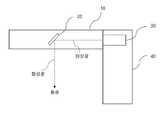
도 1은 상기 특허 문헌 1에 개시된 바와 같은 증강 현실용 광학 장치를 나타낸 도면이다.1 is a view showing an optical device for augmented reality as disclosed in Patent Document 1 above.
도 1을 참조하면, 화상 출사부(30)는 증강 현실용 화상에 상응하는 화상광을 출사하는 수단으로서 예컨대 소형 디스플레이 장치로 구현될 수 있다. 반사부(20)는 화상 출사부(30)로부터 출사된 증강 현실용 화상에 상응하는 화상광을 사용자의 동공을 향해 반사시킴으로써 증강 현실용 화상을 제공한다.Referring to FIG. 1, the
광학 수단(10)는 실제 사물로부터 출사된 화상광의 적어도 일부를 투과시키는 수단으로써 예컨대 안경 렌즈일 수 있으며, 그 내부에 반사부(20)가 매립되어 있다. 프레임부(40)는 화상 출사부(30)와 광학 수단(10)을 고정 및 지지하는 수단이다.The
도 1의 반사부(20)는, 사람의 동공 크기보다 작은 크기 즉, 8mm 이하로 형성되어 있는데, 이와 같이 반사부(20)를 동공 크기보다 작게 형성함으로써 반사부(20)를 통해 동공으로 입사하는 빛에 대한 심도(Field of Depth)를 거의 무한대에 가깝게 즉, 심도를 매우 깊게 할 수 있다. 여기서, 심도라 함은, 초점이 맞는 것으로 인식되는 범위를 말하는데, 심도가 깊어지게 되면 증강 현실용 화상에 대한 초점 거리도 깊어진다는 것을 의미하고 따라서 사용자가 실제 세계를 응시하면서 실제 세계에 대한 초점 거리를 변경하더라도 이와 관계없이 증강 현실용 화상의 초점은 항상 맞는 것으로 인식하게 된다. 이는 일종의 핀홀 효과(pin hole effect)라고 볼 수 있다. 따라서, 사용자가 실제 세계에 존재하는 실제 사물을 응시하면서 초점 거리를 변경하는 것과 상관없이 증강 현실용 화상에 대해서는 항상 선명한 가상 영상을 제공할 수 있다.The
도 2는 본 출원인에 의해 개발된 증강 현실용 광학 장치의 또 다른 예를 나타낸 도면이다.2 is a view showing another example of the optical device for augmented reality developed by the applicant.
도 2의 증강 현실용 광학 장치는, 도 1에서 설명한 바와 같은 장점을 그대로 가지되, 화상 출사부(30)로부터 출사된 증강 현실용 화상광이 광학 수단(10) 내면에서 반사되어 반사부(20)로 전달되고, 반사부(20)는 이를 동공(40)을 향해 반사시킴으로써 증강 현실용 화상을 제공하는 것을 특징으로 한다.The optical device for augmented reality of FIG. 2 has the same advantages as described in FIG. 1, but the augmented reality image light emitted from the
그러나, 도 2의 증강 현실용 광학 장치는, 증강 현실용 화상의 초점이 무한대이어야만 제대로 상이 표현된다는 문제점이 있다. 즉, 화상 출사부(30)로부터 출사되는 증강 현실용 화상광은 도 2에 나타낸 바와 같이 원칙적으로 완벽한 형태의 평행광이어야 한다.However, the optical device for augmented reality of FIG. 2 has a problem that an image is properly expressed only when the focus of the augmented reality image is infinite. That is, the image light for augmented reality emitted from the
도 3 및 도 4는 화상 출사부(30)로부터 출사되는 화상광이 평행광인 경우와 평행광이 아닌 경우를 비교설명하기 위한 것이다.3 and 4 are for comparing the case where the image light emitted from the
도 3을 참조하면, 화상 출사부(30)로부터 출사된 증강 현실용 화상에 상응하는 화상광(A,B)들은 평행광이며, 이들은 반사 미러(50)에서 반사된 후 광학 수단(10)의 내면에서 전반사되어 반사부(20)로 전달된다.Referring to Figure 3, the image light (A, B) corresponding to the augmented reality image emitted from the
이 때, 도 3에 나타낸 바와 같이, 화상광(A,B)들은 광학 수단(10)의 내면에서 반사된 후 서로 중첩됨을 알 수 있다. 따라서, 이러한 경우 반사부(20)에서 반사되어 동공(40)으로 반사될 때 사용자 입장에서는 제대로 맺힌 상을 볼 수 있을 것이다.At this time, as shown in FIG. 3, it can be seen that the image lights A and B overlap each other after being reflected from the inner surface of the
한편, 도 4는 화상 출사부(30)로부터 출사되는 화상광(A,B)들은 평행광이 아니며, 이러한 경우 반사 미러(50)를 거쳐 서로 다른 각도를 가지고 광학 수단(10)의 내면에 입사하기 때문에 광학 수단(10)의 내면에서 전반사될 때 도 3에서와 같이 중첩되지 않고 서로 다른 각도로 전반사되어 진행함을 알 수 있다. 따라서, 도 4와 같은 경우에는 반사부(20)를 통해 동공(40)으로 전달되는 화상광에 의해 형성되는 상은 어긋나거나 깨져보이게 된다. 바꾸어 말하면, 무한대의 초점을 갖는 증강 현실용 화상이 아닌 경우에는 상이 제대로 맺히지 않을 수 있다는 문제가 있으며, 이는 무한대가 아닌 초점을 갖는 근접 초점 거리의 증강 현실용 화상을 제대로 표현하기 어렵다는 것을 의미한다. 이러한 문제를 광 경로 길이 정합(optical path length matching) 또는 광 경로 길이 조절(optical path length adjusting) 문제라 하며, 도 4의 경우에는 광 경로 길이 정합이 불완전하게 되어 상 끊김 현상이 발생하게 된다.On the other hand, Figure 4 is the image light (A, B) emitted from the
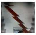
도 5 내지 도 7은 상 끊김 현상을 나타낸 실제 화면이다.5 to 7 are actual screens showing a phase break phenomenon.
도 5는 도 4에서 설명한 바와 같이 화상 출사부(30)로부터 출사되는 화상광(A,B)이 완전한 평행광이 아닌 경우로서, 근거리의 초점 거리를 갖는 가상 사물(연필)의 상이 끊겨서 표시됨을 알 수 있다. 이는 가상 사물에 상응하는 화상광이 광학 수단(10)을 통해 전달될 때 이미지가 자연스럽게 연결되지 않고 불완전한 상태로 결합되어 광 경로 길이 정합이 불완전하므로, 가상 사물(연필)이 부분 부분 끊겨서 제공됨을 알 수 있다.5 is a case where the image light A and B emitted from the
도 6은 도 5의 경우보다 초점 거리가 약간 길어진 경우로서 이 경우에도 역시 가상 사물의 상은 자연스럽게 연결되지 않고 광 경로 길이 정합이 불완전함을 알 수 있다.FIG. 6 shows that the focal length is slightly longer than that of FIG. 5, and in this case, it can be seen that the image of the virtual object is not naturally connected and the optical path length matching is incomplete.
한편, 도 7은 도 6의 경우보다 초점 거리가 상당히 길어진 경우로서 이 경우는 가상 사물의 초점 거리가 무한대에 가까운 것으로 볼 수 있으며 따라서 가상 사물로부터 출사되는 화상광(A,B)들은 도 3에서 나타낸 바와 같이 광학 수단(10)으로 평행광으로 입사하므로 왜곡이 없으며 또한 상 끊김 현상이 거의 없는 상을 사용자에게 제공할 수 있으며, 이는 광 경로 길이 정합이 거의 완전한 형태로 볼 수 있다.On the other hand, FIG. 7 is a case in which the focal length is considerably longer than that of FIG. 6, and in this case, the focal length of the virtual object is considered to be close to infinity. Therefore, the image lights A and B emitted from the virtual object are shown in FIG. 3. As shown, since it is incident to the
이러한 문제점을 해결하기 위해서는 도 8과 같은 방법을 생각할 수 있다.To solve this problem, a method as shown in FIG. 8 can be considered.
도 8은 근접 초점 거리의 증강 현실용 화상을 표시하기 위한 종래의 구성을 나타낸 것으로서, 도 8에 나타낸 바와 같이 광학 수단(10)의 앞뒤로 볼록 렌즈와 오목 렌즈의 쌍을 배치하고 근접 초점 거리를 갖는 증강 현실용 화상(가상 사물)에 대해서는 반사부(20)에서 반사된 후 오목 렌즈를 통해 화상광이 바깥쪽으로 굴절되도록 한다. 이 경우, 오목 렌즈만을 사용한다면 사용자가 광학 수단(10)을 통해 인식하는 실제 세계에 존재하는 실제 사물에 대한 상은 왜곡될 수 있으나, 광학 수단(10)의 외면에 배치된 볼록 렌즈에 의해 실제 사물에 대한 상은 안쪽으로 굴절되어 광학 수단(10)으로 입사하고 이후 오목 렌즈를 통해 다시 바깥쪽으로 굴절되기 때문에 실제 세계의 사물에 대한 상은 제대로 형성될 수 있다. 따라서, 도 8과 같은 구조를 사용하면, 근접 초점 거리의 증강 현실용 화상을 제대로 표현할 수 있다.FIG. 8 shows a conventional configuration for displaying an image for augmented reality at a close focal length, and as shown in FIG. 8, a pair of convex lenses and concave lenses is disposed back and forth of the
그러나, 도 8과 같은 구성은, 광학 수단(10)의 외부에 오목 렌즈와 볼록 렌즈와 같은 추가적인 구성을 필요로 하기 때문에 부피가 커지고 장치의 무게가 증가한다는 문제가 있다.However, the configuration as shown in FIG. 8 has a problem in that it is bulky and increases the weight of the device because it requires an additional configuration such as a concave lens and a convex lens outside the
본 발명은 상기한 바와 같은 문제점을 해결하기 위한 것으로서, 무한대의 초점 거리가 아닌 근접 초점 거리를 갖는 증강 현실용 화상을 왜곡이나 끊김없이 선명하게 사용자에게 제공할 수 있는 증강 현실용 광학 장치를 제공하는 것을 목적으로 한다.The present invention is to solve the above problems, to provide an optical device for augmented reality that can provide an augmented reality image having a near focal length rather than an infinite focal length to the user without distortion or loss. It is aimed at.
상기한 바와 같은 과제를 해결하기 위하여 본 발명은, 근접 거리의 증강 현실용 화상을 제공할 수 있는 증강 현실용 광학 장치에 있어서, 실제 사물로부터 출사된 화상광의 적어도 일부를 사용자의 눈의 동공을 향해 투과시키고, 화상 출사부로부터 출사되는 증강 현실용 화상에 상응하는 화상광을 내면에서 적어도 1회 이상 반사시켜 광학 소자로 전달하는 광학 수단; 및 상기 광학 수단의 내부에 배치되며, 상기 광학 수단을 통해 전달되는 증강 현실용 화상에 상응하는 화상광을 사용자의 눈의 동공을 향해 전달함으로써 사용자에게 증강 현실용 화상을 제공하는 적어도 하나 이상의 광학 소자를 포함하되, 상기 광학 수단은, 실제 사물로부터 출사된 화상광이 입사하는 제1 면과 상기 광학 소자를 통해 전달되는 증강 현실용 화상에 상응하는 화상광이 출사하는 제2 면을 가지되, 상기 제1 면과 제2 면은 서로 평행하지 않도록 경사각(θ)을 가지는 것을 특징으로 하는 근접 거리의 증강 현실용 화상을 제공할 수 있는 증강 현실용 광학 장치를 제공한다.In order to solve the problems as described above, the present invention, in the optical device for augmented reality capable of providing an image for augmented reality at a close distance, at least a portion of the image light emitted from a real object toward the pupil of the user's eye Optical means for transmitting and reflecting the image light corresponding to the image for augmented reality emitted from the image output unit at least once on the inner surface and transmitting it to the optical element; And at least one optical element disposed inside the optical means to provide an augmented reality image to the user by transmitting image light corresponding to the augmented reality image transmitted through the optical means toward the pupil of the user's eye. Including, but, the optical means has a first surface to which the image light emitted from a real object is incident and a second surface to which the image light corresponding to the augmented reality image transmitted through the optical element is emitted, the An optical device for augmented reality capable of providing an augmented reality image having a close distance, wherein the first surface and the second surface have an inclination angle θ so as not to be parallel to each other.
여기에서, 상기 광학 소자는, 8mm 이하의 반사 수단으로 형성된 것이 바람직하다.Here, it is preferable that the optical element is formed by a reflecting means of 8 mm or less.
또한, 상기 화상 출사부의 어느 한 점으로로부터 출사되는 화상광들은 서로 평행하지 않은 것이 바람직하다.Further, it is preferable that the image lights emitted from any one point of the image output section are not parallel to each other.
또한, 상기 화상 출사부로부터 출사된 화상광들은, 상기 광학 수단의 내면에 배치된 반사 미러에 의해 반사된 후 상기 제1 면 및 제2 면에서 적어도 1회 이상 전반사되어 광학 소자로 전달되도록 할 수도 있다.In addition, the image light emitted from the image output unit may be reflected by a reflection mirror disposed on the inner surface of the optical means and then totally reflected at least once on the first surface and the second surface to be transmitted to the optical element. have.
또한, 상기 경사각(θ)은 화상 출사부로부터 출사되는 증강 현실용 화상에 상응하는 화상광에 상응하는 증강 현실용 화상의 초점 거리(D)와 상기 화상 출사부로부터 광학 수단의 반사 미러로 입사하는 넓이(S)에 기초하여 설정되도록 구성할 수도 있다.In addition, the inclination angle θ is the focal length (D) of the image for augmented reality corresponding to the image light corresponding to the image for augmented reality emitted from the image output unit and incident from the image output unit to the reflection mirror of the optical means It can also be configured to be set based on the area (S).
또한, 상기 경사각(θ)은 tan-1(S/D)의 수식에 기초하여 설정되는 것이 바람직하다.In addition, the inclination angle θ is preferably set based on the formula of tan-1 (S / D).
또한, 상기 경사각(θ)는 0.015°~ 4.6°범위의 값을 갖도록 하는 것이 바람직하다.In addition, the inclination angle (θ) is preferably to have a value in the range of 0.015 ° ~ 4.6 °.
또한, 상기 광학 수단의 제1 면 및 제2 면 중 적어도 어느 하나는 적어도 일부분이 곡면으로 형성될 수 있다.Further, at least one of the first surface and the second surface of the optical means may be formed as a curved surface.
또한, 상기 광학 수단의 제1 면과 제2 면은 부분적으로 경사각(θ)을 가질 수 있다.Further, the first surface and the second surface of the optical means may partially have an inclination angle θ.
본 발명에 의하면, 무한대의 초점 거리가 아닌 근접 초점 거리를 갖는 증강 현실용 화상을 왜곡이나 끊김없이 선명하게 사용자에게 제공할 수 있는 증강 현실용 광학 장치를 제공할 수 있다.According to the present invention, it is possible to provide an optical device for augmented reality that can provide a user with an image for augmented reality having a close focal length rather than an infinite focal length without distortion or loss.
도 1은 특허 문헌 1에 개시된 바와 같은 증강 현실용 광학 장치를 나타낸 도면이다.
도 2는 본 출원인에 의해 개발된 증강 현실용 광학 장치의 또 다른 예를 나타낸 도면이다.
도 3 및 도 4는 화상 출사부(30)로부터 출사되는 화상광이 평행광인 경우와 평행광이 아닌 경우를 비교설명하기 위한 것이다.
도 5 내지 도 7은 상 끊김 현상을 나타낸 실제 화면이다.
도 8은 근접 초점 거리의 증강 현실용 화상을 표시하기 위한 종래의 구성을 나타낸 것이다.
도 9는 본 발명의 일실시예에 의한 증강 현실용 광학 장치(100)의 전체적인 구성을 나타낸 도면이다.
도 10 및 도 11은 도 9와 같은 구성에 의한 실제 사물에 대한 화상광의 굴절 및 이로 인한 영향을 설명하기 위한 도면이다.
도 12는 광학 수단(10)의 제1 면(11)과 제2 면(12)의 경사각(θ)을 설정하는 과정을 설명하기 위한 도면이다.1 is a view showing an optical device for augmented reality as disclosed in Patent Document 1.
2 is a view showing another example of the optical device for augmented reality developed by the applicant.
3 and 4 are for comparing the case where the image light emitted from the
5 to 7 are actual screens showing a phase break phenomenon.
8 shows a conventional configuration for displaying an image for augmented reality at a close focal length.
9 is a view showing the overall configuration of the
10 and 11 are diagrams for explaining the refraction of image light on an actual object by the configuration as shown in FIG. 9 and the effects thereof.
12 is a view for explaining a process of setting the inclination angle θ of the
이하, 첨부 도면을 참조하여 본 발명에 의한 실시예를 상세하게 설명하기로 한다.Hereinafter, embodiments according to the present invention will be described in detail with reference to the accompanying drawings.
도 9는 본 발명의 일실시예에 의한 증강 현실용 광학 장치(100)의 전체적인 구성을 나타낸 도면이다.9 is a view showing the overall configuration of the
도 9를 참조하면, 본 실시예의 증강 현실용 광학 장치(100, 이하, 간단히 "광학 장치(100)"라 한다)는, 광학 수단(10) 및 광학 소자(20)를 포함한다.Referring to FIG. 9, the optical device for augmented reality (hereinafter, simply referred to as “
광학 수단(10)은 실제 사물로부터 출사된 화상광의 적어도 일부를 사용자의 눈의 동공(40)을 향해 투과시키고, 화상 출사부(30)로부터 출사되는 증강 현실용 화상에 상응하는 화상광을 내면에서 적어도 1회 이상 반사시켜 광학 소자(20)로 전달하는 수단이다.The optical means 10 transmits at least a portion of the image light emitted from the real object toward the
또한, 광학 수단(10)은, 실제 사물로부터 출사된 화상광이 입사하는 제1 면(11)과 광학 소자(20)를 통해 전달된 증강 현실용 화상에 상응하는 화상광이 출사하는 제2 면(12)을 가지되, 상기 제1 면(11)과 제2 면(12)은 서로 평행하지 않도록 경사각(θ)을 가진다.In addition, the optical means 10 includes a
광학 소자(20)는, 광학 수단(10)의 내부에 배치되며, 광학 수단(10)을 통해 전달되는 증강 현실용 화상에 상응하는 화상광을 사용자의 동공(40)을 향해 전달함으로써 사용자에게 증강 현실용 화상을 제공하는 기능을 수행한다.The
즉, 실제 세계에 존재하는 실제 사물로부터 출사되는 화상광은 광학 수단(10)을 통해 사용자의 동공(40)으로 전달되고, 화상 출사부(30)로부터 출사되는 증강 현실용 화상광에 상응하는 화상광은 광학 수단(10) 및 광학 소자(20)에 의해 사용자의 동공(40)으로 전달되므로, 사용자는 실제 사물을 응시하면서 증강 현실용 화상을 제공받을 수 있다.That is, the image light emitted from the real object existing in the real world is transmitted to the
여기에서, 화상 출사부(30)는 증강 현실용 화상에 상응하는 화상광을 광학 수단(10)을 향해 출사하는 수단으로서, 예컨대 소형의 LCD와 같은 디스플레이 장치이거나, 디스플레이 장치로부터 출사되는 화상광을 반사 또는 굴절시켜서 광학 수단(10)을 향해 전달하는 반사 수단 또는 굴절 수단일 수 있다.Here, the
즉, 화상 출사부(30)는 증강 현실용 화상을 표시하는 디스플레이 장치이거나 이러한 디스플레이 장치로부터 출사된 화상광을 최종적으로 광학 수단(10)으로 전달하는 반사 또는 굴절 수단 등과 같은 기타 다양한 수단을 의미하며, 화상 출사부(30) 자체는 본 발명의 직접적인 목적이 아니며 종래 기술에 의해 알려져 있는 것이므로 여기에서는 상세 설명은 생략한다.That is, the
한편, 증강 현실용 화상이라 함은, 디스플레이 장치에 표시되어 광학 수단(10) 및 광학 소자(20)를 통해 사용자의 동공(40)으로 전달되는 가상 화상을 의미하며, 이미지 형태의 정지 영상이거나 동영상과 같은 것일 수 있다. 이러한 증강 현실용 화상은 디스플레이 장치로부터 화상광으로 출사되어 광학 수단(10) 및 광학 소자(20)에 의해 사용자의 동공(40)으로 전달됨으로써 가상 화상으로서 제공되고, 이와 동시에 사용자는 광학 수단(10)을 통해 실제 세계에 존재하는 실제 사물로부터 출사되는 화상광을 눈으로 직접 응시함으로써 증강 현실 서비스를 제공받게 된다.Meanwhile, the image for augmented reality refers to a virtual image displayed on a display device and transmitted to the
한편, 도 9에서 광학 소자(20)는 1개만을 나타내었으나, 복수개로 형성될 수도 있다. 복수개로 형성되는 경우, 도 9에서 가로 방향으로 일렬로 형성될 수 있다. 또한, 도 9에서의 지면 방향으로 일렬로 형성되거나 가로 방향 및 지면 방향의 조합에 의한 행렬 형태로 형성될 수도 있다.Meanwhile, in FIG. 9, only one
한편, 광학 소자(20)는 앞서 배경 기술에서 설명한 바와 같이, 심도를 깊게 하여 핀홀 효과를 얻을 수 있도록 사람의 동공 크기보다 작은 크기 즉, 8mm 이하로 형성되는 것이 바람직하다.On the other hand, as described in the background art, the
또한, 광학 소자(20)는 예컨대 소형 미러 또는 하프 미러와 같은 반사 수단이거나 회절 수단 등과 같은 것일 수 있으며, 사람의 동공 크기보다 작은 크기 즉, 8mm 이하의 반사 수단으로 형성되는 것이 바람직하다.Further, the
한편, 광학 수단(10)의 내면에는 반사 미러(50)가 배치되어 있는데, 이는 화상 출사부(30)로부터 출사된 화상광(A,B)을 반사시켜 광학 수단(10)의 내면으로 반사시켜서 전반사를 통해 화상광(A,B)가 광학 소자(20)로 전달될 수 있도록 하기 위한 수단이다.On the other hand, a
다만, 반사 미러(50)는 도 9와 같이 화상 출사부(30)가 배치된 경우에 필요한 것이며, 예컨대 화상 출사부(30)로부터 출사되는 화상광(A,B)들이 직접 광학 수단(10)의 내면에서 전반사가 이루어질 수 있도록 하는 위치에 배치되는 경우에는 생략될 수 있다.However, the
한편, 도 9에서, 화상 출사부(30)의 표면의 어느 한 점으로부터 출사되는 화상광들은, 앞서 도 4에서 설명한 바와 같이, 서로 평행하지 않은 화상광(A,B)들이며, 이들은 반사 미러(50)에 의해 반사된 후 광학 수단(10)의 제1 면(11)과 제2 면(12)에서 적어도 1회 이상 전반사된 후 광학 소자(20)로 입사한다.On the other hand, in FIG. 9, the image lights emitted from any one point on the surface of the
여기에서, 광학 수단(10)의 제1 면(11)과 제2 면(12)은 서로 평행하지 않도록 경사각(θ)을 가지도록 배치되어 있기 때문에, 화상광(A)와 화상광(B)는 서로 다른 각도를 가지고 광학 수단(10)의 제1 면(11)에서 전반사되고 광학 수단(10)의 제1 면(11)에서 처음 화상광(A)와 화상광(B)가 만나는 점부터는 화상광(A)와 화상광(B)는 중첩되어 광학 소자(20)로 전달된다.Here, since the
한편, 이와 같은 구성에 의하면, 제1 면(11)과 제2 면이 경사각(θ) 만큼 경사지게 형성되어 있으므로, 광학 수단(10)의 제1 면(11)을 통해 동공(40)으로 입사하는 실제 세계의 영상 즉, 실제 사물로부터 출사된 화상광은 광학 수단(10)을 통과할 때 굴절될 수 있으며, 이는 실제 사물에 대한 상에 영향을 줄 수 있다..On the other hand, according to such a configuration, since the
도 10 및 도 11은 도 9와 같은 구성에 의한 실제 사물에 대한 화상광의 굴절 및 이로 인한 영향을 설명하기 위한 도면이다.10 and 11 are diagrams for explaining the refraction of image light on an actual object by the configuration as shown in FIG. 9 and the effects thereof.
도 10을 참조하면, 제1 면(11)과 제2 면이 경사각(θ)을 가지고 배치되어 있으며, 광학 수단(10)의 굴절률을 n이라 할 때, 실제 사물로부터 출사되는 화상광이 광학 수단(10)으로 입사해서 굴절된 후 출사되는 출사각(θ')은 다음과 같은 관계를 만족한다.Referring to FIG. 10, when the


따라서, 사용자의 동공(40) 정면 방향에 대한 실제 사물에 대한 화상광의 출사각(θs)는 다음과 같이 구할 수 있다.Accordingly, the exit angle θs of the image light with respect to the real object with respect to the front direction of the

여기에서, θ가 0에 가까운 값을 가지면 sinθ는 θ로 수렴하고, sin-1(nsinθ)는 nθ로 볼 수 있다. 또한, 유리 재질의 광학 수단(10)인 경우 굴절률 n은 1.5이므로, 결국 θs ≒
이는 광학 수단(10)의 제1 면(11)과 제2 면(12)이 경사각(θ)을 가지고 배치되는 경우, 실제 사물은 동공(40) 정면 방향에 대해
한편, 도 11을 참조하면, 화상 출사부(30)로부터 출사된 서로 평행하지 않은 화상광(A) 및 화상광(B)이 광학 수단(10)의 제1 면(11)의 한 점에서 전반사된 후 광학 수단(10)의 제2 면(12)으로 출사할 때 경사각(θc)을 갖는데 이는 다음과 같은 관계를 만족한다.On the other hand, referring to FIG. 11, non-parallel image light A and image light B emitted from the
θc = 2θθc = 2θ
앞서 설명한 바와 같이, θ는 2θs이므로, θc≒ 4θs가 된다.As described above, θ is 2θs, so θc ≒ 4θs .
이는 광학 수단(10)의 제1 면(11)과 제2 면(12)이 경사각(θ)을 갖는 경우, 증강 현실용 화상에 상응하는 화상광에 대한 영향이 실제 세계의 실제 사물에 대한 화상광에 미치는 영향보다 4배 정도 크다는 것을 의미한다. 따라서, 증강 현실용 화상에 상응하는 화상광에 대한 상 맞춤 효과는 커지지만 이에 비해 실제 세계의 화상광에 대한 굴절 효과는 크지 않다는 것을 의미한다.This means that when the
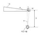
도 12는 광학 수단(10)의 제1 면(11)과 제2 면(12)의 경사각(θ)을 설정하는 과정을 설명하기 위한 도면이다.12 is a view for explaining a process of setting the inclination angle θ of the
도 12를 참조하면, 비교적 근거리의 초점 거리(D)를 갖는 가상 사물(허상)을 증강 현실용 화상으로 제공하고자 하는 경우, 가상 사물에 상응하는 화상광이 반사 미러(50)로 입사하는 넓이(S)는 다음과 같은 관계를 갖는다.Referring to FIG. 12, when a virtual object (imaginary image) having a relatively short focal length D is to be provided as an augmented reality image, an area where image light corresponding to the virtual object enters the reflection mirror 50 ( S) has the following relationship.
tanθ ≒ S/Dtanθ ≒ S / D
여기에서, θ는 가상 사물의 중심으로부터 반사 미러(50)의 최외곽으로 입사하는 화상광의 경로들 사이의 각도이며, 이를 광학 수단(10)의 제1 면(11)과 제2 면(12) 사이의 경사각(θ)으로 설정할 수 있다.Here, θ is the angle between the paths of the image light incident from the center of the virtual object to the outermost side of the
따라서, tan-1(S/D)를 계산함으로써 경사각(θ)을 계산할 수 있고, 이 계산된 결과에 근사한 값으로 광학 수단(10)의 제1 면(11)과 제2 면(12) 사이의 경사각(θ)을 설정할 수 있다.Therefore, it is possible to calculate the inclination angle θ by calculating tan-1 (S / D), and between the
즉, 광학 수단(10)의 제1 면(11)과 제2 면(12) 사이의 경사각(θ)은 증강 현실용 화상의 초점 거리(D)를 어디에 둘 것인가에 기초하여 설정할 수 있음을 의미한다.That is, the inclination angle θ between the
일반적으로 사람의 눈의 심도 범위는 ±0.3 디옵터인 것으로 알려져 있다. 따라서, 앞서 설명한 바와 같은 종래의 무한대 초점 거리를 갖는 구조에서는 초점 거리를 3,333mm(=1/0.3)보다 가깝게 하는 것이 불가능하다. 또한, 사람은 대략 125mm 이상인 경우에만 초점을 맞출 수 있으며 그 이하인 경우에는 초점을 맞출 수 없는 것으로 알려져 있다. 본 발명은 이러한 점을 고려하여, 증강 현실용 화상 즉, 가상 이미지를 3,333mm~125mm 사이에 초점을 둘 수 있도록 구성하는 것을 특징으로 한다.It is generally known that the human eye's depth range is ± 0.3 diopters. Therefore, it is impossible to make the focal length closer to 3,333 mm (= 1 / 0.3) in a structure having a conventional infinity focal length as described above. In addition, it is known that a person can focus only when it is approximately 125 mm or more, and cannot focus when it is less than that. In consideration of this point, the present invention is characterized in that an augmented reality image, that is, a virtual image is configured to focus between 3,333 mm and 125 mm.
따라서, 경사각(θ)가 가질 수 있는 바람직한 최소값과 최대값은 다음과 같이 계산할 수 있다.Therefore, the desirable minimum and maximum values that the inclination angle θ can have can be calculated as follows.
최소 경사각(θ)은 S = 3,333mm인 경우이므로, D는 사람의 동공 크기에 상응하므로 1mm~10mm의 범위의 값을 가지고 최소 경사각(θ)인 경우에는 D가 최소값을 가져야 하므로 D = 1mm 라고 하면, tanθ ≒ S/D ≒ 0.017 °가 된다.Since the minimum inclination angle (θ) is S = 3,333mm, D corresponds to the size of the pupil of the person, so it has a value in the range of 1mm to 10mm, and in the case of the minimum inclination angle (θ), D must have the minimum value, so D = 1mm If it is, it becomes tanθ ≒ S / D ≒ 0.017 °.
최대 경사각(θ)은 S = 125mm인 경우이므로, D는 사람의 동공 크기에 상응하므로 1mm~10mm의 범위의 값을 가지고 최대 경사각(θ)인 경우에는 D가 최대값을 가져야 하므로 D = 10mm 라고 하면, tanθ ≒ S/D ≒ 4.574°가 된다.Since the maximum inclination angle (θ) is in the case of S = 125mm, D is equivalent to the size of the pupil of the person, so it has a value in the range of 1mm to 10mm, and in the case of maximum inclination angle (θ), D must have the maximum value, so D = 10mm If it is, it becomes tanθ ≒ S / D ≒ 4.574 °.
따라서 경사각(θ)는 0.017°~ 4.574°사이의 값을 갖는 것이 바람직하며, 대략 0.015°~ 4.6°의 범위 이내라면 충분하다.Therefore, it is preferable that the inclination angle θ has a value between 0.017 ° and 4.574 °, and it is sufficient if it is within the range of approximately 0.015 ° to 4.6 °.
한편, 광학 수단(10)의 제1 면(11)과 제2 면(12)은 평면인 것으로 나타내었으나 이들 중 적어도 어느 하나는 적어도 일부분이 곡면으로 형성될 수도 있다.On the other hand, the
또한, 광학 수단(10)의 제1 면(11)과 제2 면(12)은 모두 평면으로 형성되어 있으므로 제1 면(11)과 제2 면(12)은 전체 면에 대해 경사각(θ)을 갖는 것으로 되어 있으나, 제1 면(11)과 제2 면(12)은 부분적으로만 경사각(θ)을 가지도록 해도 된다. 예컨대, 동공(40)의 주변부만을 경사각(θ)을 가지도록 하고 나머지 부분은 제1 면(11)과 제2 면(12)은 평행하도록 할 수도 있다.In addition, since the
이상에서 설명한 본 발명에 의한 증강 현실용 광학 장치(10)는 무한대의 초점 거리를 갖지 않는 근거리의 초점 거리를 갖는 가상 사물을 도 7의 경우와 같이 사용자에게 제공할 수 있는 효과를 갖는다.The
이상에서, 본 발명의 바람직한 실시예를 참조하여 본 발명을 설명하였으나 본 발명은 상기 실시예에 한정되는 것은 아니며 기타 다양한 수정 및 변형 실시가 가능함은 물론이다.In the above, the present invention has been described with reference to preferred embodiments of the present invention, but the present invention is not limited to the above embodiments, and various other modifications and variations can be implemented.
100...증강 현실용 광학 장치
10...광학 수단
20...광학 소자
30...화상 출사부
40...동공
50...반사 미러100 ... augmented reality optical device
10 ... optical means
20 ... optical element
30 ... Image output department
40 ... Pupil
50 ... reflective mirror
Claims (9)
Translated fromKorean실제 사물로부터 출사된 화상광의 적어도 일부를 사용자의 눈의 동공을 향해 투과시키고, 화상 출사부로부터 출사되는 증강 현실용 화상에 상응하는 화상광을 내면에서 적어도 1회 이상 반사시켜 광학 소자로 전달하는 광학 수단; 및
상기 광학 수단의 내부에 배치되며, 상기 광학 수단을 통해 전달되는 증강 현실용 화상에 상응하는 화상광을 사용자의 눈의 동공을 향해 전달함으로써 사용자에게 증강 현실용 화상을 제공하는 적어도 하나 이상의 광학 소자
를 포함하되,
상기 광학 수단은, 실제 사물로부터 출사된 화상광이 입사하는 제1 면과 상기 광학 소자를 통해 전달되는 증강 현실용 화상에 상응하는 화상광이 출사하는 제2 면을 가지되, 상기 제1 면과 제2 면은 서로 평행하지 않도록 경사각(θ)을 가지는 것을 특징으로 하는 근접 거리의 증강 현실용 화상을 제공할 수 있는 증강 현실용 광학 장치.
In the optical device for augmented reality that can provide a close-range augmented reality image,
Optical that transmits at least a portion of the image light emitted from a real object toward the pupil of the user's eye, and reflects the image light corresponding to the augmented reality image emitted from the image output unit at least once on the inner surface and transmits it to the optical element Way; And
At least one optical element disposed inside the optical means and providing an image for augmented reality to the user by transmitting image light corresponding to the image for augmented reality transmitted through the optical means toward the pupil of the user's eye
Including,
The optical means has a first surface on which the image light emitted from the real object is incident and a second surface on which the image light corresponding to the image for augmented reality transmitted through the optical element is emitted. An optical device for augmented reality capable of providing an image for augmented reality at a close distance, characterized in that the second surface has an inclination angle θ so as not to be parallel to each other.
상기 광학 소자는, 8mm 이하의 반사 수단으로 형성된 것을 특징으로 하는 근접 거리의 증강 현실용 화상을 제공할 수 있는 증강 현실용 광학 장치.
The method according to claim 1,
The optical element is an optical device for augmented reality capable of providing an image for augmented reality at a close distance, characterized in that formed by a reflecting means of 8 mm or less.
상기 화상 출사부의 어느 한 점으로로부터 출사되는 화상광들은 서로 평행하지 않은 것을 특징으로 하는 근접 거리의 증강 현실용 화상을 제공할 수 있는 증강 현실용 광학 장치.
The method according to claim 1,
The optical device for augmented reality capable of providing an augmented reality image of a close distance, characterized in that the image lights emitted from any one point of the image output unit are not parallel to each other.
상기 화상 출사부로부터 출사된 화상광들은, 상기 광학 수단의 내면에 배치된 반사 미러에 의해 반사된 후 상기 제1 면 및 제2 면에서 적어도 1회 이상 전반사되어 광학 소자로 전달되는 것을 특징으로 하는 근접 거리의 증강 현실용 화상을 제공할 수 있는 증강 현실용 광학 장치.
The method according to claim 1,
The image light emitted from the image output unit is reflected by a reflection mirror disposed on the inner surface of the optical means, and then totally reflected at least once on the first surface and the second surface and transmitted to the optical element. An optical device for augmented reality capable of providing an image for augmented reality at close range.
상기 경사각(θ)은 화상 출사부로부터 출사되는 증강 현실용 화상에 상응하는 화상광에 상응하는 증강 현실용 화상의 초점 거리(D)와 상기 화상 출사부로부터 광학 수단의 반사 미러로 입사하는 넓이(S)에 기초하여 설정되는 것을 특징으로 하는 근접 거리의 증강 현실용 화상을 제공할 수 있는 증강 현실용 광학 장치.
The method according to claim 4,
The inclination angle θ is the focal length D of the augmented reality image corresponding to the image light corresponding to the image for augmented reality emitted from the image emitting portion and the area incident from the image emitting portion to the reflection mirror of the optical means ( Optical device for augmented reality capable of providing an image for augmented reality at a close distance, which is set based on S).
상기 경사각(θ)은 tan-1(S/D)의 수식에 기초하여 설정되는 것을 특징으로 하는 근접 거리의 증강 현실용 화상을 제공할 수 있는 증강 현실용 광학 장치.
The method according to claim 5,
The inclination angle (θ) is an optical device for augmented reality that can provide an image for augmented reality at a close distance, characterized in that is set based on the formula of tan-1 (S / D).
상기 경사각(θ)는 0.015°~ 4.6°범위의 값을 갖는 것을 특징으로 하는 근접 거리의 증강 현실용 화상을 제공할 수 있는 증강 현실용 광학 장치.
The method according to claim 6,
The inclination angle θ is an optical device for augmented reality that can provide an image for augmented reality at a close distance, characterized in that it has a value in the range of 0.015 ° to 4.6 °.
상기 광학 수단의 제1 면 및 제2 면 중 적어도 어느 하나는 적어도 일부분이 곡면으로 형성된 것을 특징으로 하는 근접 거리의 증강 현실용 화상을 제공할 수 있는 증강 현실용 광학 장치.
The method according to claim 1,
At least one of the first surface and the second surface of the optical means is at least a portion of the augmented reality optical device capable of providing an augmented reality image of a close distance, characterized in that formed as a curved surface.
상기 광학 수단의 제1 면과 제2 면은 부분적으로 경사각(θ)을 갖는 것을 특징으로 하는 근접 거리의 증강 현실용 화상을 제공할 수 있는 증강 현실용 광학 장치.The method according to claim 1,
An optical device for augmented reality capable of providing an image for augmented reality at a close distance, wherein the first surface and the second surface of the optical means partially have an inclination angle θ.
Priority Applications (6)
| Application Number | Priority Date | Filing Date | Title |
|---|---|---|---|
| KR1020190016903AKR102099231B1 (en) | 2019-02-13 | 2019-02-13 | Optical device for augmented reality providing virtual image at near distance |
| EP19915533.4AEP3907552A4 (en) | 2019-02-13 | 2019-10-17 | Augmented reality optical device capable of providing augmented reality image at close range |
| JP2021547177AJP7356181B2 (en) | 2019-02-13 | 2019-10-17 | Augmented reality optical device capable of providing close-range augmented reality images |
| US17/429,238US12124047B2 (en) | 2019-02-13 | 2019-10-17 | Optical device for augmented reality capable of providing image for augmented reality having close distance |
| CN201980090514.1ACN113366376B (en) | 2019-02-13 | 2019-10-17 | Enhanced on-the-fly optical device capable of providing enhanced on-the-fly images at close range |
| PCT/KR2019/013628WO2020166785A1 (en) | 2019-02-13 | 2019-10-17 | Augmented reality optical device capable of providing augmented reality image at close range |
Applications Claiming Priority (1)
| Application Number | Priority Date | Filing Date | Title |
|---|---|---|---|
| KR1020190016903AKR102099231B1 (en) | 2019-02-13 | 2019-02-13 | Optical device for augmented reality providing virtual image at near distance |
Publications (1)
| Publication Number | Publication Date |
|---|---|
| KR102099231B1true KR102099231B1 (en) | 2020-04-08 |
Family
ID=70275546
Family Applications (1)
| Application Number | Title | Priority Date | Filing Date |
|---|---|---|---|
| KR1020190016903AActiveKR102099231B1 (en) | 2019-02-13 | 2019-02-13 | Optical device for augmented reality providing virtual image at near distance |
Country Status (6)
| Country | Link |
|---|---|
| US (1) | US12124047B2 (en) |
| EP (1) | EP3907552A4 (en) |
| JP (1) | JP7356181B2 (en) |
| KR (1) | KR102099231B1 (en) |
| CN (1) | CN113366376B (en) |
| WO (1) | WO2020166785A1 (en) |
Cited By (2)
| Publication number | Priority date | Publication date | Assignee | Title |
|---|---|---|---|---|
| WO2023128168A1 (en)* | 2021-12-28 | 2023-07-06 | 주식회사 레티널 | Compact augmented reality optical device using embedded collimator and optical element having negative refractive index |
| WO2023128167A1 (en)* | 2021-12-27 | 2023-07-06 | 주식회사 레티널 | Compact optical device for augmented reality, using negative refraction optical element |
Citations (4)
| Publication number | Priority date | Publication date | Assignee | Title |
|---|---|---|---|---|
| KR101660519B1 (en) | 2015-03-09 | 2016-09-29 | 하정훈 | Apparatus for augmented reality |
| US20170192239A1 (en)* | 2016-01-06 | 2017-07-06 | Naoki Nakamura | Light guide, virtual image display device, and light guide unit |
| KR20180025847A (en)* | 2015-07-06 | 2018-03-09 | 구글 엘엘씨 | The addition of prescription calibration to eyepieces for see-through head wearable displays |
| KR101894556B1 (en)* | 2016-09-08 | 2018-10-04 | 주식회사 레티널 | Optical device |
Family Cites Families (20)
| Publication number | Priority date | Publication date | Assignee | Title |
|---|---|---|---|---|
| JP3309615B2 (en)* | 1994-12-21 | 2002-07-29 | キヤノン株式会社 | Image observation apparatus and binocular image observation apparatus using the same |
| JP2011059444A (en)* | 2009-09-10 | 2011-03-24 | Olympus Corp | Spectacles-type image display device |
| JP5686011B2 (en)* | 2011-03-22 | 2015-03-18 | セイコーエプソン株式会社 | Image relay optical system and virtual image display device including the same |
| US8294994B1 (en) | 2011-08-12 | 2012-10-23 | Google Inc. | Image waveguide having non-parallel surfaces |
| JP6111635B2 (en)* | 2012-02-24 | 2017-04-12 | セイコーエプソン株式会社 | Virtual image display device |
| US9869861B2 (en) | 2012-11-09 | 2018-01-16 | The Arizona Board Of Regents On Behalf Of The University Of Arizona | Glass implemented display |
| JP6307793B2 (en)* | 2013-05-01 | 2018-04-11 | セイコーエプソン株式会社 | Virtual image display device |
| JP6244888B2 (en)* | 2013-09-03 | 2017-12-13 | セイコーエプソン株式会社 | Virtual image display device |
| WO2015114675A1 (en)* | 2014-01-28 | 2015-08-06 | オリンパス株式会社 | Head-mounted display device and light-guiding prism |
| JP5893077B2 (en)* | 2014-05-19 | 2016-03-23 | 株式会社東芝 | Display device |
| JP6892213B2 (en)* | 2015-04-30 | 2021-06-23 | ソニーグループ株式会社 | Display device and initial setting method of display device |
| CN107085300B (en)* | 2016-02-15 | 2021-06-22 | 精工爱普生株式会社 | Virtual image display device and method for manufacturing image element unit |
| DE102016105060B3 (en)* | 2016-03-18 | 2017-07-06 | Carl Zeiss Smart Optics Gmbh | Spectacle lens for imaging optics, imaging optics and data glasses |
| JP6812649B2 (en)* | 2016-03-24 | 2021-01-13 | セイコーエプソン株式会社 | Image display device |
| JP2018049106A (en)* | 2016-09-21 | 2018-03-29 | セイコーエプソン株式会社 | Optical element and display device |
| CN108107572B (en)* | 2016-11-25 | 2020-07-14 | 中强光电股份有限公司 | near-eye display device |
| JP6822194B2 (en)* | 2017-02-14 | 2021-01-27 | 株式会社リコー | Virtual image optical system and virtual image display device |
| KR20180106624A (en)* | 2017-03-21 | 2018-10-01 | 주식회사 파노비젼 | Optic system of see-through head mounted display having expanding manners for horizontal and vertical exit pupils |
| JP6917571B2 (en)* | 2017-03-28 | 2021-08-11 | パナソニックIpマネジメント株式会社 | Display device |
| KR102728848B1 (en)* | 2022-11-24 | 2024-11-13 | 주식회사 레티널 | Optical device for augmented reality which can prevent ghost image |
- 2019
- 2019-02-13KRKR1020190016903Apatent/KR102099231B1/enactiveActive
- 2019-10-17CNCN201980090514.1Apatent/CN113366376B/enactiveActive
- 2019-10-17JPJP2021547177Apatent/JP7356181B2/enactiveActive
- 2019-10-17USUS17/429,238patent/US12124047B2/enactiveActive
- 2019-10-17WOPCT/KR2019/013628patent/WO2020166785A1/ennot_activeCeased
- 2019-10-17EPEP19915533.4Apatent/EP3907552A4/enactivePending
Patent Citations (4)
| Publication number | Priority date | Publication date | Assignee | Title |
|---|---|---|---|---|
| KR101660519B1 (en) | 2015-03-09 | 2016-09-29 | 하정훈 | Apparatus for augmented reality |
| KR20180025847A (en)* | 2015-07-06 | 2018-03-09 | 구글 엘엘씨 | The addition of prescription calibration to eyepieces for see-through head wearable displays |
| US20170192239A1 (en)* | 2016-01-06 | 2017-07-06 | Naoki Nakamura | Light guide, virtual image display device, and light guide unit |
| KR101894556B1 (en)* | 2016-09-08 | 2018-10-04 | 주식회사 레티널 | Optical device |
Cited By (2)
| Publication number | Priority date | Publication date | Assignee | Title |
|---|---|---|---|---|
| WO2023128167A1 (en)* | 2021-12-27 | 2023-07-06 | 주식회사 레티널 | Compact optical device for augmented reality, using negative refraction optical element |
| WO2023128168A1 (en)* | 2021-12-28 | 2023-07-06 | 주식회사 레티널 | Compact augmented reality optical device using embedded collimator and optical element having negative refractive index |
Also Published As
| Publication number | Publication date |
|---|---|
| JP7356181B2 (en) | 2023-10-04 |
| US12124047B2 (en) | 2024-10-22 |
| JP2022520398A (en) | 2022-03-30 |
| CN113366376A (en) | 2021-09-07 |
| EP3907552A1 (en) | 2021-11-10 |
| CN113366376B (en) | 2023-11-03 |
| WO2020166785A1 (en) | 2020-08-20 |
| US20220137422A1 (en) | 2022-05-05 |
| EP3907552A4 (en) | 2022-03-30 |
Similar Documents
| Publication | Publication Date | Title |
|---|---|---|
| KR102192942B1 (en) | Optical device for augmented reality having improved light efficiency | |
| KR102255781B1 (en) | Compatct type optical device for augmented reality | |
| US11536963B2 (en) | Optical device for augmented reality having improved light efficiency | |
| KR102200144B1 (en) | Compact type optical device for augmented reality which can prevent ghost images with wide field of view | |
| KR102099231B1 (en) | Optical device for augmented reality providing virtual image at near distance | |
| KR102248606B1 (en) | Compact type optical device for augmented reality having reflective means arranged in curved line | |
| KR102438997B1 (en) | Optical device for augmented reality with vision correction function | |
| KR102323201B1 (en) | Optical device for augmented reality having reflective means arranged in curved line for light efficiency | |
| JP7202740B2 (en) | Compact augmented reality optical device | |
| KR102386259B1 (en) | Optical device for augmented reality having visual acuity correction function | |
| KR20210053249A (en) | Compact type optical device for augmented reality which can prevent ghost images with wide field of view | |
| KR20210004835A (en) | Camera module using small reflective surface and optical device for augmented reality using the camera module | |
| KR102303641B1 (en) | Optical device for augmented reality | |
| KR102302159B1 (en) | Optical device for augmented reality preventing light leakage | |
| KR102452963B1 (en) | Compact type optical device for augmented reality using total internal reflection | |
| KR102437585B1 (en) | Optical device for augmented reality which can prevent ghost images | |
| KR102334813B1 (en) | Optical device for augmented reality which can prevent ghost images | |
| US12248163B2 (en) | Optical device for augmented reality having improved light transmittance | |
| KR102353010B1 (en) | Optical device for augmented reality having visual acuity correction function | |
| KR102216587B1 (en) | Optical device for augmented reality which can prevent ghost images |
Legal Events
| Date | Code | Title | Description |
|---|---|---|---|
| PA0109 | Patent application | Patent event code:PA01091R01D Comment text:Patent Application Patent event date:20190213 | |
| PA0201 | Request for examination | ||
| E701 | Decision to grant or registration of patent right | ||
| PE0701 | Decision of registration | Patent event code:PE07011S01D Comment text:Decision to Grant Registration Patent event date:20200326 | |
| GRNT | Written decision to grant | ||
| PR0701 | Registration of establishment | Comment text:Registration of Establishment Patent event date:20200403 Patent event code:PR07011E01D | |
| PR1002 | Payment of registration fee | Payment date:20200403 End annual number:3 Start annual number:1 | |
| PG1601 | Publication of registration | ||
| PR1001 | Payment of annual fee | Payment date:20221202 Start annual number:4 End annual number:4 | |
| PR1001 | Payment of annual fee | Payment date:20240108 Start annual number:5 End annual number:5 | |
| PR1001 | Payment of annual fee | Payment date:20250114 Start annual number:6 End annual number:6 |