KR102096612B1 - 3-dimensional intraoral scanner - Google Patents
3-dimensional intraoral scannerDownload PDFInfo
- Publication number
- KR102096612B1 KR102096612B1KR1020190059581AKR20190059581AKR102096612B1KR 102096612 B1KR102096612 B1KR 102096612B1KR 1020190059581 AKR1020190059581 AKR 1020190059581AKR 20190059581 AKR20190059581 AKR 20190059581AKR 102096612 B1KR102096612 B1KR 102096612B1
- Authority
- KR
- South Korea
- Prior art keywords
- case
- camera
- light
- distance
- image
- Prior art date
- Legal status (The legal status is an assumption and is not a legal conclusion. Google has not performed a legal analysis and makes no representation as to the accuracy of the status listed.)
- Active
Links
Images


Classifications
- A—HUMAN NECESSITIES
- A61—MEDICAL OR VETERINARY SCIENCE; HYGIENE
- A61C—DENTISTRY; APPARATUS OR METHODS FOR ORAL OR DENTAL HYGIENE
- A61C9/00—Impression cups, i.e. impression trays; Impression methods
- A61C9/004—Means or methods for taking digitized impressions
- A61C9/0046—Data acquisition means or methods
- A61C9/0053—Optical means or methods, e.g. scanning the teeth by a laser or light beam
- A—HUMAN NECESSITIES
- A61—MEDICAL OR VETERINARY SCIENCE; HYGIENE
- A61B—DIAGNOSIS; SURGERY; IDENTIFICATION
- A61B1/00—Instruments for performing medical examinations of the interior of cavities or tubes of the body by visual or photographical inspection, e.g. endoscopes; Illuminating arrangements therefor
- A61B1/00163—Optical arrangements
- A61B1/00186—Optical arrangements with imaging filters
- A—HUMAN NECESSITIES
- A61—MEDICAL OR VETERINARY SCIENCE; HYGIENE
- A61B—DIAGNOSIS; SURGERY; IDENTIFICATION
- A61B5/00—Measuring for diagnostic purposes; Identification of persons
- A61B5/0059—Measuring for diagnostic purposes; Identification of persons using light, e.g. diagnosis by transillumination, diascopy, fluorescence
- A61B5/0082—Measuring for diagnostic purposes; Identification of persons using light, e.g. diagnosis by transillumination, diascopy, fluorescence adapted for particular medical purposes
- A61B5/0088—Measuring for diagnostic purposes; Identification of persons using light, e.g. diagnosis by transillumination, diascopy, fluorescence adapted for particular medical purposes for oral or dental tissue
- A—HUMAN NECESSITIES
- A61—MEDICAL OR VETERINARY SCIENCE; HYGIENE
- A61B—DIAGNOSIS; SURGERY; IDENTIFICATION
- A61B1/00—Instruments for performing medical examinations of the interior of cavities or tubes of the body by visual or photographical inspection, e.g. endoscopes; Illuminating arrangements therefor
- A61B1/00163—Optical arrangements
- A61B1/00172—Optical arrangements with means for scanning
- A—HUMAN NECESSITIES
- A61—MEDICAL OR VETERINARY SCIENCE; HYGIENE
- A61B—DIAGNOSIS; SURGERY; IDENTIFICATION
- A61B1/00—Instruments for performing medical examinations of the interior of cavities or tubes of the body by visual or photographical inspection, e.g. endoscopes; Illuminating arrangements therefor
- A61B1/24—Instruments for performing medical examinations of the interior of cavities or tubes of the body by visual or photographical inspection, e.g. endoscopes; Illuminating arrangements therefor for the mouth, i.e. stomatoscopes, e.g. with tongue depressors; Instruments for opening or keeping open the mouth
- A—HUMAN NECESSITIES
- A61—MEDICAL OR VETERINARY SCIENCE; HYGIENE
- A61B—DIAGNOSIS; SURGERY; IDENTIFICATION
- A61B5/00—Measuring for diagnostic purposes; Identification of persons
- A61B5/0059—Measuring for diagnostic purposes; Identification of persons using light, e.g. diagnosis by transillumination, diascopy, fluorescence
- A61B5/0062—Arrangements for scanning
- A—HUMAN NECESSITIES
- A61—MEDICAL OR VETERINARY SCIENCE; HYGIENE
- A61B—DIAGNOSIS; SURGERY; IDENTIFICATION
- A61B5/00—Measuring for diagnostic purposes; Identification of persons
- A61B5/0059—Measuring for diagnostic purposes; Identification of persons using light, e.g. diagnosis by transillumination, diascopy, fluorescence
- A61B5/0073—Measuring for diagnostic purposes; Identification of persons using light, e.g. diagnosis by transillumination, diascopy, fluorescence by tomography, i.e. reconstruction of 3D images from 2D projections
Landscapes
- Health & Medical Sciences (AREA)
- Life Sciences & Earth Sciences (AREA)
- Surgery (AREA)
- Veterinary Medicine (AREA)
- Public Health (AREA)
- General Health & Medical Sciences (AREA)
- Animal Behavior & Ethology (AREA)
- Physics & Mathematics (AREA)
- Medical Informatics (AREA)
- Biophysics (AREA)
- Biomedical Technology (AREA)
- Heart & Thoracic Surgery (AREA)
- Molecular Biology (AREA)
- Pathology (AREA)
- Engineering & Computer Science (AREA)
- Radiology & Medical Imaging (AREA)
- Nuclear Medicine, Radiotherapy & Molecular Imaging (AREA)
- Optics & Photonics (AREA)
- Dentistry (AREA)
- Oral & Maxillofacial Surgery (AREA)
- Audiology, Speech & Language Pathology (AREA)
- Epidemiology (AREA)
- Endoscopes (AREA)
- Dental Tools And Instruments Or Auxiliary Dental Instruments (AREA)
Abstract
Translated fromKorean
Description
Translated fromKorean본 발명은 3차원 구강 스캐너에 관한 것으로서, 보다 상세하게는 적어도 하나의 카메라를 통해 측정 대상물을 용이하게 측정할 수 있는 3차원 구강 스캐너에 관한 것이다.The present invention relates to a 3D oral scanner, and more particularly, to a 3D oral scanner that can easily measure a measurement object through at least one camera.
일반적으로, 구강 스캐너는 치과 환자의 구강 내에 삽입되어 비접촉식으로 치아를 스캐닝함으로써 치열에 대한 3차원 스캐닝 모델을 생성하기 위한 광학장치이다.In general, an oral scanner is an optical device that is inserted into the oral cavity of a dental patient and scans a tooth in a non-contact manner to generate a three-dimensional scanning model for dentition.
단일 카메라를 이용하여 다중 시점(view)에서 측정한 영상을 이용하여 3차원 정보를 획득하는 종래 기술로는, 서로 다른 시점의 영상의 좌표계를 이용하여 물체와 카메라간의 거리 정보를 구하는 방법으로 연속으로 촬영된 영상 정보를 정합하여 각 영상에서 서로 일치하는 물체를 찾은 후 사형식(projection)을 이용하여 물체의 거리 정보를 추출한다. 따라서, 3차원 정보를 처리하는데 어려움이 존재하고 계산량이 많아지는 문제가 있으며, 최근에는 두 개 이상의 카메라에서 얻어진 이미지를 이용하는 스테레오 비전(stereo vision) 방식이 구강 스캐너에 적용되고 있다.As a conventional technique for acquiring 3D information using an image measured at multiple views using a single camera, it is a method of continuously obtaining a distance information between an object and a camera using a coordinate system of images of different views. After matching the captured image information to find objects that match each other, the distance information of the object is extracted using projection. Therefore, there is a problem in that it is difficult to process 3D information and a calculation amount is increased, and recently, a stereo vision method using an image obtained from two or more cameras is applied to an oral scanner.
하지만, 스테레오 비전 방식을 이용한 3차원 데이터 측정의 경우, 최소한 두 대 이상의 카메라가 필요하고, 두 대의 카메라는 동일한 방향으로 측정대상을 바라보아야 하므로 두 대의 카메라를 수용하기 위한 구강 스캐너 내부 공간의 활용에 제약이 생기는 문제가 있고, 제품 전체의 크기가 증대하게 되어 기구 설계 제작이 어려운 문제가 있다.However, in the case of 3D data measurement using the stereo vision method, at least two cameras are required, and the two cameras need to look at the measurement object in the same direction, so it is necessary to utilize the space inside the oral scanner to accommodate the two cameras. There is a problem that constraints occur, and the size of the entire product increases, which makes it difficult to design and manufacture a mechanism.
도 1은 구강 스캐너를 이용한 3차원 정보 획득 모식도 및 편광판 적용 모식도이다.1 is a schematic diagram of obtaining 3D information using an oral scanner and a schematic diagram of applying a polarizing plate.
일반적으로 구강 스캐너를 이용하여 구강 내의 치아에 관한 3차원 스캐닝 모델을 형성하기 위해서는, 도 1의 (a)에 도시된 바와 같이, 측정 대상물(O)인 치아에 구조광을 투영하고 그로부터 반사된 빛을 획득하여 이로부터 3차원 데이터를 획득하는 방식을 취한다.In general, in order to form a three-dimensional scanning model of a tooth in the oral cavity using an oral scanner, as shown in FIG. 1 (a), the structured light is projected onto a tooth that is the object to be measured (O) and the light reflected therefrom And acquires 3D data therefrom.
즉, 광 발생부(170)로부터 발생된 광(光)은 프로젝션 렌즈(171)를 투과하여 측정 대상물(O)인 치아를 포함한 구강 내부에서 반사된 후 카메라 렌즈(121)를 통하여 내부로 입사되어 이미징 센서(130)를 통하여 3차원 데이터가 획득된다.That is, the light (light) generated from the
이러한 방식으로 치아에 관한 정밀한 표면 데이터를 획득하기 위해서는 투영된 구조광이 측정 대상물(O)의 표면인 치아에 정확히 투사되고 이를 획득하는 것이 중요하다. 그러나, 석고 모델과 같이 투사된 빛이 표면에서 반사되는 표면 반사(Surface reflection) 재질이 아닌 치아와 같은 내부 반사(Inner reflection) 재질인 경우 물체의 투영된 빛이 측정 대상물의 표면 뿐만 아니라 재질 내부로 투과되어 반사되는 영향으로 정확한 3차원 데이터를 획득할 수 없는 기술적인 문제가 있었다.In order to obtain precise surface data on the teeth in this way, it is important that the projected structural light is accurately projected onto the surface of the object to be measured (O) and obtained. However, if the projected light is a material that is an inner reflection material such as a tooth rather than a surface reflection material that reflects the light from the surface, such as a plaster model, the projected light of the object is measured not only on the surface of the object to be measured, but also inside the material. There is a technical problem in that accurate 3D data cannot be obtained due to the transmitted and reflected effects.
이를 해결하기 위하여, 광학적 파동 특성을 활용하여 측정 대상물의 내부 반사 재질의 표면에서만 반사된 빛을 획득하는 방법들(예를 들면 편광판을 이용하는 방법)이 연구 및 개발되고 있는 실정이나, 편광판을 이용하는 경우에도 3차원 데이터의 손실이 없도록 정밀한 축(axis) 조절 및 편광판 자체의 표면 반사 문제로 인한 적용에 어려움이 있는 실정이다.In order to solve this, methods for obtaining light reflected only from the surface of the internal reflective material of a measurement object by utilizing optical wave characteristics (for example, a method using a polarizing plate) are being researched and developed, or when using a polarizing plate Edo is difficult to apply due to precise axis adjustment and surface reflection problems of the polarizer itself so that there is no loss of 3D data.
아울러, 편광판을 적용하는 경우에도 도 1의 (b)에 도시된 바와 같이, 광 발생부(170)로부터 광이 측정 대상물(O)에 투사되기 전의 투사 경로에 제1편광판(180a)을 구비하고, 측정 대상물(O)로부터 반사되어 카메라 렌즈(121)로 입사되기 전의 입사 경로에 제2편광판(180b)을 구비하여야 하는데, 이는 단일 카메라의 경우 적어도 2개의 편광판(180a,180b)을 구비하여야 함을 의미하고, 나아가 스테레오 비전 방식이 적용된 경우에는 적어도 3개의 편광판을 구비하여야 함을 의미하는 바, 전체적인 제품의 슬림 설계가 매우 난망한 문제점으로 이어진다.In addition, even when a polarizing plate is applied, as shown in FIG. 1 (b), the first polarizing
본 발명의 목적은, 측정 대상물의 측정과 동시에 3차원 이미지 데이터의 확보가 가능함은 물론, 사용자의 파지가 용이하도록 본체 케이스의 슬림 제조가 가능한 3차원 구강 스캐너를 제공하는 것이다.An object of the present invention is to provide a three-dimensional oral scanner that is capable of securing three-dimensional image data simultaneously with measurement of an object to be measured, as well as slim manufacturing of a body case to facilitate gripping by a user.
또한, 본 발명의 다른 목적은, 측정 대상물을 측정함에 있어서 치아와 같은 내부 반사 물질에 의한 내부 반사 광을 제거하여 보다 선명하고 정밀한 측정이 가능하도록 하는 3차원 구강 스캐너를 제공하는 것이다.In addition, another object of the present invention is to provide a three-dimensional oral scanner that enables a clearer and more precise measurement by removing internal reflected light by an internal reflective material such as a tooth in measuring a measurement object.
아울러, 본 발명의 다른 목적은, 환자의 구강 내부로 인입 가능하게 구비된 팁 케이스의 슬림 제조가 가능하면서 고스트 이미지 또는 노이즈가 발생하지 않는 최적의 설계안을 제공할 수 있는 3차원 구강 스캐너를 제공하는 것이다.In addition, another object of the present invention is to provide a three-dimensional oral scanner that can provide an optimal design that does not generate ghost images or noise while allowing slim production of a tip case provided to be inserted into a patient's mouth. will be.
본 발명의 기술적 과제들은 이상에서 언급한 과제들로 제한되지 않으며, 언급되지 않은 또 다른 기술적 과제들은 아래의 기재들로부터 당업자에게 명확하게 이해될 수 있을 것이다.The technical problems of the present invention are not limited to the problems mentioned above, and other technical problems not mentioned will be clearly understood by those skilled in the art from the following descriptions.
상기의 목적을 달성하기 위한 본 발명의 일 실시예에 따른 3차원 구강 스캐너는, 구강 내에 인입 및 인출이 가능하고, 일단부를 통해 상기 구강 내부의 모습(이하, '화상'이라 약칭함)이 광의 형태로 내부로 입사되도록 개구된 개구부가 형성된 케이스, 상기 케이스의 내부에 배치되고, 상기 케이스의 개구부를 통하여 입사된 광을 통과시키도록 배치된 적어도 하나의 카메라, 상기 적어도 하나의 카메라 사이에 배치되어 상기 개구부를 통해 상기 구강 내부로 광을 조사하는 광 프로젝터 및 상기 적어도 하나의 카메라와 상기 개구부 사이에 위치되되, 상기 적어도 하나의 카메라 전단으로부터 설정거리(d)만큼 이격된 위치에 위치된 단일 편광 필터를 포함한다.The 3D oral scanner according to an embodiment of the present invention for achieving the above object is capable of being drawn in and out of the oral cavity, and the shape of the inside of the oral cavity (hereinafter abbreviated as 'image') is broad through one end. A case in which an opening is formed so as to be incident to the inside in a shape, and is disposed inside the case, and disposed between the at least one camera and at least one camera disposed to pass light incident through the opening of the case. An optical projector that irradiates light into the oral cavity through the opening, and a single polarization filter positioned between the at least one camera and the opening, and positioned at a predetermined distance (d) from the front end of the at least one camera. It includes.
여기서, 상기 설정거리(d)는, 상기 광 프로젝터로부터 상기 구강 내부로 투사되는 투사 화각과, 상기 구강 내부로부터 반사되어 상기 적어도 하나의 카메라로 입사되는 이미지 화각이 상호 겹치지 않는 거리로 설정될 수 있다.Here, the set distance (d) may be set to a distance in which the projection angle of view projected from the light projector into the oral cavity and the image angle of view reflected from the interior of the oral cavity do not overlap each other. .
또한, 상기 설정거리(d)는, 상기 광 프로젝터로부터 상기 구강 내부로 투사되는 광이 상기 단일 편광 필터에 의하여 반사된 반사 광 형태로 상기 적어도 하나의 카메라로 입사되지 않도록 설정될 수 있다.Further, the set distance d may be set such that light projected from the optical projector into the oral cavity does not enter the at least one camera in the form of reflected light reflected by the single polarization filter.
또한, 상기 설정거리(d)는, 상기 단일 편광 필터가 상기 적어도 하나의 카메라를 향하여 접근할수록 상기 단일 편광 필터의 상하 폭 및 좌우 폭(이하, '전체 크기'라고 약칭함)이 증가한다고 전제할 때, 상기 단일 편광 필터의 전체 크기가 가장 작은 위치에 설정될 수 있다.In addition, the set distance (d), it is assumed that as the single polarization filter approaches the at least one camera, the vertical width and the left and right widths of the single polarization filter (hereinafter abbreviated as 'total size') increase. At this time, the entire size of the single polarization filter may be set at the smallest position.
또한, 상기 설정거리(d)는, 다음의 수학식을 만족할 수 있다.Further, the set distance d may satisfy the following equation.
즉, 수학식 : 이고, 여기서, d는 상기 설정거리이고, 는 광 프로젝터로부터 화상까지의 거리이며, 는 일측 카메라 렌즈로부터 화상까지의 거리이고, 는 삼각측량 각도이며, D는 일측 카메라 렌즈의 구경이고, 는 투사 화각이다.That is, Equation: where d is the set distance, is the distance from the optical projector to the image, is the distance from the one camera lens to the image, is the triangulation angle, and D is the aperture of the one camera lens , And is the projection angle of view.
또한, 상기 케이스는, 상기 적어도 하나의 카메라 및 이를 구동시키기 위한 각종 전장 부품이 내장되는 본체 케이스 및 상기 본체 케이스의 일단부에 결합되고, 상기 개구부가 형성된 팁 케이스를 포함하고, 상기 단일 편광 필터는, 상기 설정거리(d)가 상기 팁 케이스에 위치되도록 설치될 수 있다.Further, the case includes a body case in which the at least one camera and various electric components for driving the same are embedded, and a tip case coupled to one end of the body case, wherein the opening is formed, and the single polarization filter is , The set distance (d) may be installed to be located in the tip case.
또한, 상기 팁 케이스의 내부에는 상기 단일 편광 필터의 상단 및 하단이 삽입되어 설치되는 상단 설치 리브 및 하단 설치 리브가 일체로 형성될 수 있다.In addition, the inside of the tip case may be formed integrally with the upper mounting rib and the lower mounting rib where the upper and lower ends of the single polarization filter are inserted and installed.
본 발명에 따른 3차원 구강 스캐너의 다른 실시예는, 구강 내에 인입 및 인출이 가능하고, 일단부를 통해 상기 구강 내부의 모습(이하, '화상'이라 약칭함)이 광의 형태로 내부로 입사되도록 개구된 개구부가 형성된 케이스, 상기 케이스의 내부에 배치되고, 상기 케이스의 개구부를 통하여 입사된 광을 통과시키도록 배치된 적어도 하나의 카메라, 상기 적어도 하나의 카메라의 일측에 배치되어 상기 개구부를 통해 상기 구강 내부로 광을 조사하는 광 프로젝터 및 상기 적어도 하나의 카메라와 상기 개구부 사이에 위치되되, 상기 광 프로젝터로부터 상기 구강 내부로 투사되는 투사 화각과, 상기 구강 내부로부터 반사되어 적어도 하나의 카메라로 입사되는 이미지 화각이 상호 겹쳐지지 않도록 수평 배치되는 단일 편광 필터를 포함한다.Another embodiment of the three-dimensional oral scanner according to the present invention, it is possible to enter and withdraw in the oral cavity, and the opening of the inside of the oral cavity (hereinafter abbreviated as an 'image') through one end is incident to the inside in the form of light A case in which the opened opening is formed, disposed at the inside of the case, and at least one camera disposed to pass light incident through the opening of the case, disposed at one side of the at least one camera, and the oral cavity through the opening An image projector that is located between the at least one camera and the opening, and an optical projector that irradiates light inside, and a projection angle of view projected from the optical projector to the inside of the oral cavity, and an image reflected from the inside of the oral cavity and incident on at least one camera It includes a single polarization filter arranged horizontally so that the angle of view does not overlap with each other.
본 발명에 따른 3차원 구강 스캐너의 또 다른 실시예는, 구강 내에 인입 및 인출이 가능하고, 본체 내부로 입사되는 입사광 및 본체 내부로부터 출사되는 출사광을 반사시키는 반사 부재가 구비된 케이스, 상기 케이스의 내부에 배치되고, 상기 케이스의 반사 부재를 통하여 입사된 입사광을 각각 상이한 경로로 통과시키도록 배치된 한 쌍의 스테레오 카메라, 상기 한 쌍의 스테레오 카메라 사이에 배치되어 상기 반사 부재를 통해 상기 구강 내부로 상기 출사광을 조사하는 광 프로젝터 및 상기 한 쌍의 스테레오 카메라와 상기 반사 부재 사이에 위치되되, 상기 광 프로젝터와 평행되게 배치되는 단일 편광 필터를 포함한다.Another embodiment of the three-dimensional oral scanner according to the present invention is a case provided with a reflective member capable of being drawn in and out of the oral cavity, and reflecting incident light entering the main body and exiting light emitted from the main body, the case A pair of stereo cameras disposed inside the pair of stereo cameras arranged to pass incident light incident through the reflective member of the case through different paths, and disposed between the pair of stereo cameras through the reflective member inside the oral cavity And a single polarization filter disposed between the pair of stereo cameras and the reflective member, and disposed in parallel with the optical projector.
본 발명의 일 실시예에 다른 3차원 구강 스캐너에 따르면 다음과 같은 다양한 효과를 달성할 수 있다.According to another 3D oral scanner according to an embodiment of the present invention, various effects such as the following can be achieved.
첫째, 이미징 센서가 부착된 이미징 보드를 본체 케이스의 내측벽에 결합시키되, 입사 광을 굴절 또는 변경시키도록 구비함으로써 사용자의 파지가 용이한 본체 케이스의 슬림 제조가 가능한 효과를 가진다.First, the imaging board with the imaging sensor is coupled to the inner wall of the main body case, but by providing the incident light to be refracted or changed, the user has the effect of being able to manufacture a slim body case that is easy to grip.
둘째, 단일 편광 필터를 통하여 측정 대상물로부터 발생되는 이미지 데이터의 손실없이 정확한 스캔이 이루어지도록 함으로써 제품의 신뢰성을 향상시킬 수 있는 효과를 가진다.Second, it has an effect of improving the reliability of the product by making an accurate scan without loss of image data generated from a measurement object through a single polarization filter.
셋째, 단일 편광 필터의 최적의 위치 설계안을 제시함으로써, 환자의 구강 내부로 유입되는 팁 케이스의 슬림 설계가 가능한 효과를 가진다.Third, by presenting an optimal position design plan of a single polarization filter, a slim design of a tip case flowing into a patient's mouth has a possible effect.
도 1은 구강 스캐너를 이용한 3차원 정보 획득 모식도 및 편광판 적용 모식도이고,
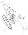
도 2는 본 발명에 따른 3차원 구강 스캐너의 일 실시예를 나타낸 사시도이며,
도 3은 도 2의 분해 사시도이고,
도 4는 도 2의 A-A선을 따라 취한 단면도이며,
도 5는 도 2의 구성 중 한 쌍의 스테레오 카메라를 이용한 광 경로를 나타낸 사시도이고,
도 6은 도 2의 구성 중 단일 편광 필터의 위치 설계를 설명하기 위한 평면 모식도이며,
도 7은 도 6의 이미지 화각, 투사 화각 및 삼각측량 각도를 나타낸 평면 모식도이다.1 is a schematic diagram of obtaining 3D information using an oral scanner and a schematic diagram of applying a polarizing plate,
Figure 2 is a perspective view showing an embodiment of a three-dimensional oral scanner according to the present invention,
Figure 3 is an exploded perspective view of Figure 2,
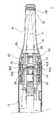
4 is a cross-sectional view taken along line AA of FIG. 2,
5 is a perspective view showing an optical path using a pair of stereo cameras in the configuration of FIG. 2,
6 is a schematic plan view for explaining a position design of a single polarization filter in the configuration of FIG. 2,
FIG. 7 is a plan view schematically showing the image angle of view, the projection angle of view, and the triangulation angle of FIG. 6.
이하, 본 발명의 일부 실시예들을 예시적인 도면을 통해 상세하게 설명한다. 각 도면의 구성요소들에 참조부호를 부가함에 있어서, 동일한 구성요소들에 대해서는 비록 다른 도면상에 표시되더라도 가능한 한 동일한 부호를 가지도록 하고 있음에 유의해야 한다. 또한, 본 발명의 실시예를 설명함에 있어, 관련된 공지 구성 또는 기능에 대한 구체적인 설명이 본 발명의 실시예에 대한 이해를 방해한다고 판단되는 경우에는 그 상세한 설명은 생략한다.Hereinafter, some embodiments of the present invention will be described in detail through exemplary drawings. It should be noted that in adding reference numerals to the components of each drawing, the same components have the same reference numerals as possible even though they are displayed on different drawings. In addition, in describing the embodiments of the present invention, when it is determined that detailed descriptions of related well-known configurations or functions interfere with the understanding of the embodiments of the present invention, detailed descriptions thereof will be omitted.
본 발명의 실시예의 구성요소를 설명하는 데 있어서, 제1, 제2, A, B, (a), (b) 등의 용어를 사용할 수 있다. 이러한 용어는 그 구성요소를 다른 구성요소와 구별하기 위한 것일 뿐, 그 용어에 의해 해당 구성 요소의 본질이나 차례 또는 순서 등이 한정되지 않는다. 또한, 다르게 정의되지 않는 한, 기술적이거나 과학적인 용어를 포함해서 여기서 사용되는 모든 용어들은 본 발명이 속하는 기술분야에서 통상의 지식을 가진 자에 의해 일반적으로 이해되는 것과 동일한 의미를 가진다. 일반적으로 사용되는 사전에 정의되어 있는 것과 같은 용어들은 관련 기술의 문맥상 가지는 의미와 일치하는 의미를 가진 것으로 해석되어야 하며, 본 출원에서 명백하게 정의하지 않는 한, 이상적이거나 과도하게 형식적인 의미로 해석되지 않는다.In describing the components of the embodiments of the present invention, terms such as first, second, A, B, (a), and (b) may be used. These terms are only for distinguishing the component from other components, and the nature, order, or order of the component is not limited by the term. In addition, unless defined otherwise, all terms used herein, including technical or scientific terms, have the same meaning as commonly understood by a person skilled in the art to which the present invention pertains. Terms, such as those defined in a commonly used dictionary, should be interpreted as having meanings consistent with meanings in the context of related technologies, and should not be interpreted as ideal or excessively formal meanings unless explicitly defined in the present application. Does not.
도 2는 본 발명에 따른 3차원 구강 스캐너의 일 실시예를 나타낸 사시도이고, 도 3은 도 2의 분해 사시도이며, 도 4는 도 2의 A-A선을 따라 취한 단면도이고, 도 5는 도 2의 구성 중 한 쌍의 스테레오 카메라를 이용한 광 경로를 나타낸 사시도이며, 도 6은 도 2의 구성 중 단일 편광 필터의 위치 설계를 설명하기 위한 평면 모식도이다.Figure 2 is a perspective view showing an embodiment of a three-dimensional oral scanner according to the present invention, Figure 3 is an exploded perspective view of Figure 2, Figure 4 is a cross-sectional view taken along line AA of Figure 2, Figure 5 is of Figure 2 It is a perspective view showing an optical path using a pair of stereo cameras in the configuration, and FIG. 6 is a schematic plan view for explaining the position design of a single polarization filter in the configuration in FIG. 2.
본 발명에 따른 3차원 구강 스캐너의 일 실시예는, 도 1 내지 도 4에 참조된 바와 같이, 구강 내에 인입 및 인출이 가능한 케이스(10)를 포함한다.One embodiment of the three-dimensional oral scanner according to the present invention, as referred to in Figures 1 to 4, includes a case 10 that can be drawn in and out in the oral cavity.
케이스(10)의 내부에는, 적어도 하나의 카메라(20)가 배치될 수 있다. 즉, 적어도 하나의 카메라(20)는, 도면에 도시되지 않았으나, 단일 카메라(20)로서, 케이스(10)의 내부에 배치될 수 있다. 또한, 적어도 하나의 카메라(20)는, 도 3에 참조된 바와 같이, 한 쌍의 스테레오 카메라(20)로서, 케이스(10)의 내부에 배치될 수 있다.At least one camera 20 may be disposed inside the case 10. That is, at least one camera 20, although not shown in the drawing, as a single camera 20, may be disposed inside the case 10. Also, at least one camera 20 may be disposed inside the case 10 as a pair of stereo cameras 20, as shown in FIG. 3.
이때, 적어도 하나의 카메라(20)가 한 쌍의 스테레오 카메라(20)로 배치되는 경우에는, 케이스(10)의 일단부로부터 입사된 광을 각각 상이한 경로로 통과시키도록 케이스(10)의 폭 방향으로 이격되게 배치될 수 있다. 이하에서는, 설명의 편의를 위하여 적어도 하나의 카메라(90)가 케이스(10)의 내부에 배치된 것을 전제로 설명하나, 단일 카메라(20)의 적용을 완전히 배제하는 것은 아님에 주의하여야 한다.At this time, when the at least one camera 20 is disposed as a pair of stereo cameras 20, the width direction of the case 10 so as to pass light incident from one end of the case 10 through different paths, respectively. It can be arranged spaced apart. Hereinafter, for convenience of description, it is assumed that at least one camera 90 is disposed inside the case 10, but it should be noted that the application of the single camera 20 is not completely excluded.
여기서, '광(光)'이라 함은, 넓은 의미로서는, 사람의 눈으로 볼 수 있는 가시광선 영역의 빛을 의미하는 것이나, 특별한 광학 장치를 이용하여 관찰할 수 있는 적외선 또는 자외선 영역의 빛을 모두 포함하는 개념일 수 있고, 좁은 의미로서는, 측정하고자 하는 환자의 구강 내부의 모습(이하, '화상'이라 약칭함)을 말하는 것일 수 있다.Here, the term 'light' means, in a broad sense, light in the visible region visible to the human eye, or light in the infrared or ultraviolet region that can be observed using a special optical device. It may be an all-inclusive concept, and in a narrow sense, it may refer to a state in the oral cavity of the patient to be measured (hereinafter, abbreviated as “image”).
따라서, 케이스(10)에는 일단부를 통해 화상이 광의 형태로 내부로 유입되도록 개구된 개구부(16)가 구비될 수 있다. 개구부(16)는, 케이스(10) 외부의 광이 케이스(10)의 내부로 유입되는 입구일 수 있다. 개구부(16)를 통하여 입사된 광은 각각 상이한 광 경로를 형성하면서 한 쌍의 스테레오 카메라(20) 각각으로 투과하게 된다. 한 쌍의 스테레오 카메라(20)를 투과한 광은 후술하는 이미징 보드(31a,32a)에 구비된 이미징 센서(31b,32b)를 통해 화상이 촬영된다.Therefore, the case 10 may be provided with an
여기서, 화상은 동시에 2개의 이미지 데이터로 확보될 수 있으므로, 한 쌍의 스테레오 카메라(20)의 이격 거리 및 각 스테레오 카메라(20)를 통하여 촬영된 대상지점의 초점 거리를 알면 화상의 3차원 영상 데이터를 확보할 수 있게 된다.Here, since the image can be secured with two image data at the same time, when the separation distance of a pair of stereo cameras 20 and the focal length of the target point photographed through each stereo camera 20 are known, 3D image data of the image Will be able to secure it.
한 쌍의 스테레오 카메라(20)는, 구체적으로 도시되지 않았지만, 구강 내의 화상에 대하여 초점 조절이 가능한 적어도 2 이상의 투과 렌즈를 포함할 수 있다.The pair of stereo cameras 20, although not specifically shown, may include at least two or more transmission lenses capable of focusing on images in the oral cavity.
이를 위해, 본 발명에 따른 3차원 구강 스캐너(1)의 일 실시예는, 한 쌍의 스테레오 카메라(20)를 투과한 광을 각각 이미징 처리하는 이미징 센서(31b,32b)를 가진 이미징 보드(31a,32a)를 더 포함할 수 있다. 아울러, 본 발명에 따른 3차원 구강 스캐너(1)의 일 실시예는, 한 쌍의 스테레오 카메라(20)의 작동을 제어하기 위한 전장부품이 실장된 카메라 제어 보드 및 스캐닝된 이미지를 처리하기 위한 전장부품이 실장된 스캐닝 제어 보드를 더 포함할 수 있다.To this end, one embodiment of the three-dimensional
케이스(10)는, 도 2 내지 도 4에 참조된 바와 같이, 상술한 한 쌍의 스테레오 카메라(20), 이미징 보드(31a,32a), 카메라 제어 보드(미도시) 및 스캐닝 제어 보드(미도시)가 내장되도록 소정 공간을 제공하는 역할을 한다.The case 10, as referenced in Figs. 2 to 4, the pair of stereo cameras 20, the
보다 상세하게는, 케이스(10)는, 도 3에 참조된 바와 같이, 상기 구성들이 내장되는 소정 공간이 형성된 로워 케이스(12)와, 로워 케이스(12)의 상측에 구비되되, 로워 케이스(12)에 착탈 가능하게 결합되어 상기 구성들을 커버하는 어퍼 케이스(13)로 이루어진 본체 케이스(11)를 포함한다.More specifically, the case 10 is provided on the upper side of the
아울러, 케이스(10)는, 본체 케이스(11)의 일단부에 결합되고, 상술한 개구부(16)가 형성되어 개구부(16)를 통해 본체 케이스(11) 내부로 입사되는 광 및 개구부(16)를 통해 본체 케이스(11) 내부로부터 출사되는 광을 가이드하는 입출광 경로부(17)가 형성된 팁 케이스(14)를 더 포함할 수 있다.In addition, the case 10 is coupled to one end of the
여기서, 개구부(16)를 통해 본체 케이스(11) 내부로 입사되는 광(이하, '입사 광'이라 한다)은, 환자의 구강 내부의 모습인 화상을 의미하고, 개구부(16)를 통해 본체 케이스(11) 내부에서 출사되는 광(이하, '출사광'이라 한다)은, 후술하는 광 프로젝터(70)로부터 조사되는 조사 광을 의미한다.Here, the light incident into the
팁 케이스(14)의 내부에는, 상기 입사 광과 출사광이 용이하게 케이스(10)의 내외부로 조사되는 광 가이드 구조가 형성될 수 있다. 아울러, 개구부(16)는, 팁 케이스(14)의 길이 방향에 대하여 직교되는 일측 방향으로 개구되게 형성되고, 개구부(16)에는, 후술하는 반사 부재(60)가 배치될 수 있다.Inside the
한 쌍의 스테레오 카메라(20)의 전단부는, 상술한 바와 같이, 팁 케이스(14) 측에서 수렴되게 배치되되, 팁 케이스(14) 측으로 소정거리 오버랩되게 배치될 수 있다. 아울러, 한 쌍의 스테레오 카메라(20)의 후단부는, 본체 케이스(11)의 내부에 고정된 카메라 마운팅부(50)에 연결되도록 구비될 수 있다.As described above, the front ends of the pair of stereo cameras 20 are converged on the
한편, 본 발명에 따른 3차원 구강 스캐너(1)의 일 실시예는, 도 3 및 도 4에 참조된 바와 같이, 케이스(10)의 내부에 배치되고, 한 쌍의 스테레오 카메라(20) 사이를 통하여 소정의 출사광을 방사하되, 케이스(10) 중 팁 케이스(14)의 전단부에 형성된 개구부(16)를 통하여 상기 출사광을 조사하는 광 프로젝터(70)를 더 포함할 수 있다.On the other hand, an embodiment of the three-dimensional
아울러, 본 발명에 따른 3차원 구강 스캐너(1)의 일 실시예는, 도 3 내지 도 5에 참조된 바와 같이, 한 쌍의 스테레오 카메라(20)와 개구부(16) 사이에 위치되되, 한 쌍의 스테레오 카메라(20) 전단으로부터 설정거리(d)만큼 이격된 위치에 위치된 단일 편광 필터(80)를 더 포함할 수 있다.In addition, one embodiment of the three-dimensional
본 발명에 따른 3차원 구강 스캐너(1)의 일 실시예는, 상술한 바와 같은 구성들을 케이스(10) 내부에 배치하되, 사용자 측면에서는 본 발명에 따른 3차원 구강 스캐너(1)를 쉽게 파지하여 사용할 수 있도록 본체 케이스(11)의 슬림 제조를 도모함은 물론, 치과 환자 측면에서는 구강으로 인입 및 인출이 용이하도록 팁 케이스(14)를 가능한 한 길고 슬림하게 형성할 수 있는 최적의 배치 구조를 제안한다.One embodiment of the three-dimensional oral scanner (1) according to the present invention, the arrangement as described above is disposed inside the case (10), but from the user's side, the three-dimensional oral scanner (1) according to the present invention is easily gripped In order to facilitate the manufacture of the
여기서, 본체 케이스(11)의 슬림화 설계는, 후술하는 바와 같이, 한 쌍의 스테레오 카메라(20) 각각을 통하여 입사되는 입사 광마다 별도로 구비되는 이미징 센서(31b,32b)의 배치 설계와 관계가 있는 한편, 팁 케이스(14)의 슬림화 설계는, 후술하는 바와 같이, 단일 편광 필터(80)의 배치 설계와 관계가 있다.Here, the slim design of the
이하, 본체 케이스(11)의 슬림화 설계 방안을 보다 상세하게 설명하기로 한다.Hereinafter, the slimming design method of the
케이스(10)의 내부에는, 도 3에 참조된 바와 같이, 한 쌍의 스테레오 카메라(20)의 일단부는 팁 케이스(14) 측을 향하여 돌출되도록 구비되고, 한 쌍의 카메라의 타단부가 삽입 설치됨과 아울러, 한 쌍의 스테레오 카메라(20)를 투과한 입사 광 또는 광 프로젝터(70)로부터 조사되는 출사광의 경로인 광도파관을 형성하는 카메라 마운팅부(50)가 배치될 수 있다.Inside the case 10, as shown in FIG. 3, one end of the pair of stereo cameras 20 is provided to protrude toward the
카메라 마운팅부(50)에 형성된 광도파관은, 개구부(16)로부터 입사되는 입사 광과 광 프로젝터(70)로부터 조사되는 출사광이 상호 구획되어 영향을 미치지 않도록 암실 형태로 구비될 수 있다.The optical waveguide formed in the
즉, 광도파관은, 광 프로텍터로부터 조사된 출사광의 팁 케이스(14) 측까지의 광 경로를 제공하는 출사광 경로부(53)와, 한 쌍의 스테레오 카메라(20) 중 일측의 카메라를 통해 입사되는 입사 광의 광 경로를 제공하는 일측 입사광 경로부(51)와, 한 쌍의 스테레오 카메라(20) 중 타측의 카메라를 통해 입사되는 입사 광의 광 경로를 제공하는 타측 입사광 경로부(52)를 포함할 수 있다.That is, the optical waveguide is incident through the camera on one side of the pair of stereo cameras 20 and the output
여기서, 출사광 경로부(53)와 일측 입사광 경로부(51) 및 타측 입사광 경로부(52) 각각은 상호 구획되도록 구비됨으로써 각각의 경로의 광이 상호 영향을 전혀 미치지 않게 구비될 수 있다.Here, each of the exiting
아울러, 광 프로텍터는 케이스(10)의 폭 방향으로 상호 소정거리 이격되게 배치된 한 쌍의 스테레오 카메라(20)의 타단부 중앙 부분에 위치되는 바, 출사광 경로부(53)는 일측 입사광 경로부(51)와 타측 입사광 경로부(52) 사이에 형성될 수 있다.In addition, the light protector is located in the center portion of the other end of the pair of stereo cameras 20 arranged at a predetermined distance from each other in the width direction of the case 10, and the exit
일측 입사광 경로부(51) 및 타측 입사광 경로부(52)는, 한 쌍의 스테레오 카메라(20)로부터 입사되는 입사 광이 투광되도록 각각에 대응되는 스테레오 카메라의 길이방향과 일치하도록 형성되되, 각각 카메라 마운팅부(50)의 일측면 및 타측면으로 개구되도록 형성될 수 있다.One side of the incident
여기서, 이미징 센서(31b,32b)가 집적된 이미징 보드(31a,32a)는, 케이스(10)의 폭방향 일측벽 및 폭방향 타측벽에 밀착되도록 상하 수직되게 배치될 수 있다. 보다 상세하게는, 일측의 이미징 보드(31a,32a)는, 카메라 마운팅부(50)의 일측면에 밀착되도록 배치되되, 케이스(10)의 폭방향 일측벽 사이에 배치될 수 있다. 아울러, 타측의 이미징 보드(31a,32a)는, 카메라 마운팅부(50)의 타측면에 밀착되도록 배치되도, 케이스(10)의 폭방향 타측벽 사이에 배치될 수 있다. 이때, 일측의 이미징 보드(31a,32a)는, 그에 집적된 이미징 센서(31b,32b)가 일측 입사광 경로부(51)에 노출되도록 구비되고, 타측의 이미징 보드(31a,32a)는, 그에 집적된 이미징 센서(31b,32b)가 타측 입사광 경로부(52)에 노출되도록 구비될 수 있다.Here, the
한편, 본 발명에 따른 3차원 구강 스캐너(1)의 일 실시예는, 한 쌍의 스테레오 카메라(20)를 각각 투과한 입사 광의 경로를 이미징 보드(31a,32a)에 집적된 이미징 센서(31b,32b)를 향하여 각각 변경시키도록 배치된 한 쌍의 광경로 변경 미러(41,42)를 더 포함할 수 있다.On the other hand, an embodiment of the three-dimensional
한 쌍의 광경로 변경 미러(41,42) 중 하나는, 일측 입사광 경로부(51)를 통하여 투과된 입사 광을 일측의 이미징 보드(31a,32a)에 집적된 이미징 센서(31b,32b)로 조사되도록 입사 광의 경로를 변경시키는 일측 광경로 변경 미러(41)이고, 한 쌍의 광경로 변경 미러(41,42) 중 다른 하나는, 타측 입사광 경로부(52)를 통하여 투과된 입사 광을 타측의 이미징 보드(31a,32a)에 집적된 이미징 센서(31b,32b)로 조사되도록 입사 광의 경로를 변경시키는 타측 광경로 변경 미러(42)일 수 있다.One of the pair of optical
여기서의 한 쌍의 광경로 변경 미러(41,42)는, 광의 전반사가 가능한 전반사 거울을 포함할 수 있다. 그러나, 반드시 전반사 거울만으로 한정되는 것은 아니고, 전반사가 가능한 여하한 광학 요소도 포함할 수 있다.Here, the pair of light
본 발명에 따른 3차원 구강 스캐너(1)의 일 실시예는, 한 쌍의 스테레오 카메라(20)를 이용하여 환자의 구강 내부 모습(즉, 화상)의 3차원 영상 데이터를 확보하는 것을 주요 기술적 요지로 한다.One embodiment of the three-dimensional oral scanner (1) according to the present invention, using a pair of stereo camera 20 to secure the three-dimensional image data of the inside of the patient's mouth (that is, the image) the main technical point Shall be
그런데, 상술한 바와 같이, 한 쌍의 스테레오 카메라(20)의 일단부(도면상 팁 케이스(14)가 구비된 방향을 말함)는 각각 하나의 개구부(16)에 구비된 반사 부재(60)를 향하도록 상호 수렴되는 각도를 가지도록 배치되는 한편, 한 쌍의 스테레오 카메라(20)의 타단부(도면상 광 프로젝터(70)가 구비된 방향을 말함)는 각각을 투과한 입사 광을 직선 방향으로 투과시키는 구조를 가져야 한다.By the way, as described above, one end of the pair of stereo cameras 20 (referring to the direction in which the
따라서, 한 쌍의 이미징 보드(31a,32a)를 한 쌍의 스테레오 카메라(20) 각각의 타단부의 일직선 방향에 대하여 직교되도록 케이스(10)의 폭방향으로 이격되게 배치되어야 한다. 그러나, 이 경우, 한 쌍의 이미징 보드(31a,32a)의 길이에 의하여 본체 케이스(11)의 폭방향 두께를 증가시킬 우려가 있다.Therefore, the pair of
본 발명에 따른 3차원 구강 스캐너(1)의 일 실시예는, 상술한 바와 같이, 입사광 경로부(51,52)가 카메라 마운팅부(50)의 일측면 및 타측면으로 각각 개구되도록 형성됨과 아울러, 이미징 보드(31a,32a)의 설치 위치를 카메라 마운팅부(50)의 일측면과 타측면 및 케이스(10)의 일측벽과 타측벽 사이에 수직 배치하고, 한 쌍의 스테레오 카메라(20)를 통과한 입사 광의 광 경로를 변경시키는 한 쌍의 광경로 변경 미러(41,42)를 구비함으로써, 본체 케이스(11)를 측정자가 엄지 손가락, 집게 손가락 및 가운데 손가락만으로 손쉽게 파지하여 사용할 수 있도록 슬림하게 형성할 수 있다.In one embodiment of the three-dimensional
한 쌍의 광경로 변경 미러(41,42)는, 한 쌍의 스테레오 카메라(20)를 투과한 입사 광이 한 쌍의 이미징 보드(31a,32a)에 구비된 각각의 이미징 센서(31b,32b)의 일면에 직각으로 입사되는 각도의 리플렉터면을 가지도록 배치될 수 있다.The pair of optical
이를 위해, 한 쌍의 광경로 변경 미러(41,42)는, 리플렉터면이 케이스(10)의 길이방향에 대하여 경사지게 배치될 수 있다. 즉, 일측 광경로 변경 미러(41)는, 일측 스테레오 카메라(21)를 투과한 입사 광이 일측 입사광 경로부(51)를 통해 입사된 후 일측 광경로 변경 미러(41)의 리플렉터면에 의해 굴절되어 일측 이미징 보드(31a)의 이미징 센서(31b,32b)에 조사되도록 구비될 수 있다. 마찬가지로, 타측 광경로 변경 미러(42)는, 타측 스테레오 카메라(22)를 투과한 입사 광이 타측 입사광 경로부(52)를 통해 입사된 후 타측 광경로 변경 미러(42)의 리플렉터면에 의해 굴절되어 타측 이미징 보드(31b)의 이미징 센서(31b,32b)에 조사되도록 구비될 수 있다.To this end, the pair of light
다음으로, 팁 케이스(14)의 슬림화 설계 방안을 보다 상세하게 설명하기로 한다.Next, the slimming design method of the
도 6은 도 2의 구성 중 단일 편광 필터의 위치 설계를 설명하기 위한 평면 모식도이고, 도 7은 도 6의 이미지 화각(92a,92b), 투사 화각(91) 및 삼각측량 각도를 나타낸 평면 모식도이다.6 is a schematic plan view for explaining the position design of a single polarization filter in the configuration of FIG. 2, and FIG. 7 is a schematic plan view showing the image angles of
본 발명에 따른 3차원 구강 스캐너의 일 실시예는, 도 3 내지 도 5에 참조된 바와 같이, 본체 케이스(11)의 전단부 측에 한 쌍의 스테레오 카메라(20)가 팁 케이스(14)가 구비된 측으로 소정길이 오버랩되게 구비되고, 한 쌍의 스테레오 카메라(20) 사이를 통하여 광이 출사되도록 광 프로젝터(70)가 설치될 수 있다.One embodiment of the three-dimensional oral scanner according to the present invention, as shown in FIGS. 3 to 5, a pair of stereo cameras 20 on the front end side of the
여기서, 본 발명에 따른 3차원 구강 스캐너의 일 실시예는, 치아와 같이 내부 반사 물질로 이루어진 측정 대상물(100)의 내부 반사광은 제거하고 표면 반사광만 필터링하여 통과하도록 단일 편광 필터(80)가 구비될 수 있다.Here, one embodiment of the three-dimensional oral scanner according to the present invention, a
단일 편광 필터(80)는, 케이스(10) 중 팁 케이스(14)에 위치되도록 설치될 수 있다. 보다 상세하게는, 팁 케이스(14)의 내부에는, 도 4에 참조된 바와 같이, 상단 설치 리브(미도시) 및 하단 설치 리브(81)가 일체로 형성될 수 있다. 즉, 단일 편광 필터(80)는, 팁 케이스(14)의 내부에 일체로 형성된 상단 설치 리브 및 하단 설치 리브(81)에 각각 상단과 하단이 끼워져 설치될 수 있다.The
단일 편광 필터(80)는, 한 쌍의 스테레오 카메라(20)와 개구부(16) 사이에 해당하는 팁 케이스(14) 내부에 위치되되, 한 쌍의 스테레오 카메라(20)의 전단으로부터 설정거리(d)만큼 이격된 위치에 위치될 수 있다.The
보다 상세하게는, 단일 편광 필터(80)는, 도 6에 참조된 바와 같이, 광 프로젝터(70)에 의하여 출사된 광이 투사하는 투사 화각(91) 및 측정 대상물(100)로부터 반사된 광으로서 한 쌍의 스테레오 카메라(20)로 각각 입사되는 2개소의 이미지 화각(92a,92b)이 상호 겹치지 않는 거리로 상기 설정거리(d)가 설정되는 것이 바람직하다.More specifically, as shown in FIG. 6, the
즉, 광 프로젝터(70)로부터 출사된 광은, 도 6에 참조된 바와 같이, 단일 편광 필터(80)를 관통한 후 개구부(16)를 통하여 측정 대상물(100)이 위치된 환자의 구강 내부로 투사되는데, 여기서 광 프로젝터(70)로부터 출사된 광이 단일 편광 필터(80)를 투과한 최대 면적을 상술한 바와 같이 투사 화각(91)으로 정의할 수 있다.That is, the light emitted from the
또한, 광 프로젝터(70)로부터 출사되어 환자의 구강 내부로 투사된 광은, 측정 대상물(100)로부터 반사되는 반사 광 형태로 다시 개구부(16)를 통하여 팁 케이스(14) 내부로 유입된 후 본체 케이스(11)의 폭 방향으로 이격되게 배치된 한 쌍의 스테레오 카메라(20) 각각으로 입사되는데, 여기서 한 쌍의 스테레오 카메라(20) 각각으로 입사될 때 단일 편광 필터(80)를 투과한 최대 면적을 상술한 바와 같이 이미지 화각(92a,92b)으로 정의할 수 있다.In addition, the light emitted from the
여기서, 단일 편광 필터(80)가 설치된 위치가 투사 화각(91) 및 이미지 화각(92a,92b)이 상호 겹치는 위치로 설정될 경우에는, 광 프로젝터(70)로부터 투사된 광이 단일 편광 필터(80)의 투과면에서 자체 반사되어 한 쌍의 스테레오 카메라(20)로 입사될 수 있다. 이 경우에는, 이미징 센서(31b,32b)를 통해 획득한 이미지는 주변 이미지보다 밝은 상점이 생성되는 이른 바 고스트 이미지 또는 노이즈가 발생할 수 있다.Here, when the position where the
그러므로, 본 발명에 따른 3차원 구강 스캐너(1)의 일 실시예에서는, 상술한 고스트 이미지 또는 노이즈가 발생하는 것을 사전에 차단할 수 있도록 단일 편광 필터(80)를 통해 투과되면서 형성하는 투사 화각(91) 및 이미지 화각(92a,92b)이 상호 겹치지 않는 위치에 상기 설정거리(d)가 설정되도록 설계될 수 있다.Therefore, in one embodiment of the three-dimensional
즉, 단일 편광 필터(80)가 위치를 정의하는 상기 설정거리(d)는, 광 프로젝터(70)로부터 구강 내부로 투사되는 광이 단일 편광 필터(80)에 의하여 반사된 반사 광 형태로 한 쌍의 스테레오 카메라 각각으로 입사되지 않도록 설정될 수 있다.That is, the set distance (d) in which the
이론적으로, 상기 설정거리(d)는, 투사 화각(91) 및 이미지 화각(92a,92b)이 상호 겹쳐지지 않는 범위에 단일 편광 필터(80)를 위치시키도록 설정되면 족하므로, 단일 편광 필터(80)를 한 쌍의 스테레오 카메라(20)의 전단에 최대한 근접되게 위치시킬 수 있다. 그러나 이 경우에는 팁 케이스(14)의 슬림 제조를 위한 최초 취지에 어긋나는 문제점이 있다.Theoretically, the set distance d is sufficient to set the
즉, 본 발명의 일 실시예에서, 단일 카메라가 적용된 경우에는, 적어도 단일 편광 필터(80)의 크기가 물리적으로 상술한 투사 화각(91) 및 이미지 화각(도 6의 도면부호 92a 및 92b 중 어느 하나 참조)의 크기보다 더 클 것이 요구되는 바, 단일 카메라의 전단에 단일 편광 필터(80)를 최대한 근접 위치되도록 설계된 경우에는 불가피하게 그 폭방향의 증가가 예상된다.That is, in one embodiment of the present invention, when a single camera is applied, at least the size of the
또한, 본 발명의 일 실시예에서, 상술한 단일 카메라를 이용할 때 제기되는 단점을 극복하기 위하여, 한 쌍의 스테레오 카메라(20)가 적용된 경우에는, 한 쌍의 스테리오 카메라(20)를 본체 케이스(11)의 폭 방향으로 설치하되, 한 쌍의 스테레오 카메라(20) 전단이 팁 케이스(14)로 오버랩되도록 설정되어 있다. 여기서, 단일 편광 필터(80)는 적어도 이미지 화각(92a,92b)이 구현될 수 있는 크기로 제조되어야 하는 바, 단일 편광 필터(80)가 상술한 바와 같이 한 쌍의 스테레오 카메라(20) 측으로 최대한 근접 설계된 경우에는 불가피하게 그 폭방향 크기가 증가하여야 하므로, 팁 케이스(14)의 슬림 설계를 저해하는 문제가 발생한다.In addition, in one embodiment of the present invention, in order to overcome the disadvantages of using the single camera described above, when a pair of stereo cameras 20 is applied, the pair of stereo cameras 20 is the main body case It is installed in the width direction of (11), but is set so that the front end of the pair of stereo cameras 20 overlap with the
본 발명에 따른 3차원 구강 스캐너(1)의 일 실시예는, 상술한 바와 같은 문제점의 해결을 위하여, 단일 편광 필터(80)의 설정거리(d)는, 단일 편광 필터(80)가 한 쌍의 스테레오 카메라(20)를 향하여 접근할수록 단일 편광 필터(80)의 상하 폭 및 좌우 폭(이하, '전체 크기'라고 약칭함)이 증가한다고 전제할 때, 상기 단일 편광 필터(80)의 전체 크기가 가장 작은 위치에 설정될 수 있다.One embodiment of the three-dimensional
또한, 본 발명에 따른 3차원 구강 스캐너(1)의 일 실시예에서는, 단일 편광 필터(80)를 한 쌍의 스테레오 카메라(20)에 최소 이격거리를 가지도록 접근시키더라도 단일 편광 필터(80)와 주변 구성품 간 기구적 또는 구조적인 간섭이 없는 위치로 설정되어야 할 것이다.In addition, in one embodiment of the three-dimensional
이를 위해, 단일 편광 필터(80)의 최적의 설정거리(d)는, 도 7에 참조된 바와 같이, 다음의 수학식을 만족하도록 설정될 수 있다.To this end, the optimal set distance d of the

여기서, d는 상기 설정거리이고,


위 수학식 1에 따르면, 설정거리(d)는 작으면 작을수록 좋으므로, 단일 편광 필터(80)는 한 쌍의 스테레오 카메라(20)와의 기구 간섭이 발생하지 않는 한 최소한의 거리까지 근접 위치시킬 수 있게 된다. 그러나, 상술한 바와 같이, 단일 편광 필터(80)가 한 쌍의 스테레오 카메라(20)에 근접될 경우 전체 크기가 증가하는 문제가 있으므로, 이 경우에도 본 발명의 일 실시예에서의 슬림 제조라는 취지를 고려한 설계가 이루어져야 할 것이다.According to
여기서, 도 7을 참조하면, D는 일측 카메라 렌즈(21)의 구경으로써, D의 증가는 설정거리(d)가 더 작도록 설계되어야 함을 의미하고 슬림화 설계의 저해 요소가 된다. 따라서, D는 가능한 한 최소화 설계하는 것이 바람직하고, 광 프로젝터(70)와 한 쌍의 스테레오 카메라(21,22) 각각은 상기 기구 간섭이 이루어지지 않는 최적의 구조 설계가 우선되어야 한다.Here, referring to FIG. 7, D is the aperture of the one-
아울러, 본 발명에 따른 3차원 구강 스캐너의 일 실시예는, 도 7에 참조된 바와 같이, 투사 화각(91)을 형성하는 단일 편광 필터(80)를 통하여 직접 반사광(L1)이 카메라(21)로 투과되지 않아야 하는 조건을 만족하여야 한다. 여기서, 일측 카메라 렌즈(21)의 구경(D)의 증가는 이미지 화각(92b)의 증가로 이어지고, 이 경우 투사 화각(91)과 이미지 화각(92b)이 상호 겹쳐질 수 있는 바, 설정거리(d)는 더 작도록 설계되어야 한다.In addition, an embodiment of the three-dimensional oral scanner according to the present invention, as shown in FIG. 7, the reflected light L1 through the
상술한 수학식 1은 이와 같은 취지들을 모두 구현할 수 있는 단일 편광 필터(80)의 최적의 설정거리(d)를 도출하는 이론적 배경을 제시한다.
한편, 팁 케이스(14)에 형성된 개구부(16)에는 상술한 바와 같이 반사 부재(60)가 구비될 수 있다. 반사 부재(60)는, 본체 케이스(11) 내부로 입사되는 입사 광 및 본체 케이스(11) 내부로부터 출사되는 출사광을 일정 경로로 반사시키는 역할을 한다. 이와 같은, 반사 부재(60)는, 미러(mirror) 또는 프리즘 형태로 구비될 수 있다.On the other hand, the
특히, 반사 부재(60)는, 케이스(10)의 길이방향에 대하여 직교되는 어느 일 방향으로 개구되게 형성된 개구부(16)를 통해 한 쌍의 스테레오 카메라(20)를 통한 촬영이 용이하도록 한다.In particular, the
여기서, 단일 편광 필터(80)는, 한 쌍의 스테레오 카메라(20)와 반사 부재(60) 사이에 위치되되, 광 프로젝터(70)와 평행되게 배치될 수 있다. 단일 편광 필터(80)가 광 프로젝터(70)와 평행되게 배치된다는 의미는, 종래 광 프로젝터(70)로부터의 출사광의 출사 경로 및 카메라 렌즈로의 입사광의 입사 경로마다 각각의 편광 필터를 구비하되, 편광 효율의 저하를 위해 매우 정교하게 각각의 편광 필터의 위치를 설계하던 복잡한 과정을 삭제할 수 있는 이점을 가진다는 것을 의미한다.Here, the
상기와 같이 구성되는 본 발명에 따른 3차원 구강 스캐너(1)의 작동 모습을 첨부된 도면(특히, 도 3 내지 도 6)을 참조하여 보다 상세히 설명하면 다음과 같다.The operation of the 3D
측정자가 환자의 구강 내로 본 발명에 따른 3차원 구강 스캐너(1)의 일 실시예를 이용하여 측정을 하기 위해 케이스(10)의 상부에 구비된 작동 버튼부(15)를 누른다.The operator presses the
그러면, 도 5 및 도 7에 참조된 바와 같이, 광 프로젝터(70)로부터 출사광이 조사된다. 광 프로젝터(70)로부터 조사된 출사광은, 순차적으로 카메라 마운팅부(50)에 형성된 광도파관 중 출사광 경로부(53) 및 팁 케이스(14)에 형성된 입출광 경로부(17)를 경유하여 개구부(16) 측으로 조사되고, 반사 부재(60)에 의하여 개구부(16)를 통해 환자의 구강 내부에 조사된다.Then, as shown in FIGS. 5 and 7, the light emitted from the
동시에, 도 5 및 도 6에 참조된 바와 같이, 측정자가 작동 버튼부(15)를 누르는 동작에 의해 한 쌍의 스테레오 카메라(20)가 작동됨으로써 화상의 어느 일 지점을 동일한 초점으로 하는 2개의 이미지 데이터를 확보할 수 있다.At the same time, as shown in Figs. 5 and 6, a pair of stereo cameras 20 are operated by the action of the operator pressing the
이때, 환자의 구강 화상은 출사광에 의하여 광의 형태로 존재하는 것으로서, 출사광과는 반대로, 순차적으로 개구부(16)를 통해 팁 케이스(14) 내부로 입사되되, 반사 부재(60)를 통해 경로가 변경되고, 실질적으로 반사 부재(60)의 반사면을 촬영하는 한 쌍의 카메라 렌즈 각각으로 상술한 입출광 경로부(17), 대응하는 스테레오 카메라 및 광도파관 중 대응하는 입사광 경로부(51,52)를 경유하여 입사된다. 그리고, 각각의 광경로 변경 미러(41,42)에 의하여 해당하는 이미징 보드(31a,32a)의 이미징 센서(31b,32b)에 조사됨으로써 소정의 화상 데이터 2개를 동시에 확보할 수 있다. 이와 같이 확보된 2개의 화상 데이터를 토대로 환자의 구강 화상에 관한 3차원 데이터가 용이하게 확보될 수 있다.At this time, the oral image of the patient is present in the form of light by the emitted light, and, contrary to the emitted light, sequentially enters into the
이상, 본 발명에 따른 3차원 구강 스캐너의 일 실시예를 첨부된 도면을 참조하여 상세하게 설명하였다. 그러나, 본 발명의 실시예가 반드시 상술한 일 실시예에 의하여 한정되는 것은 아니고, 본 발명이 속하는 기술분야에서 통상의 지식을 가진 자에 의한 다양한 변형 및 균등한 범위에서의 실시가 가능함은 당연하다고 할 것이다. 그러므로, 본 발명의 진정한 권리범위는 후술하는 청구범위에 의하여 정해진다고 할 것이다.The embodiments of the 3D oral scanner according to the present invention have been described above in detail with reference to the accompanying drawings. However, the embodiments of the present invention are not necessarily limited to the above-described embodiments, and it is natural that various modifications and equivalent implementations are possible by those skilled in the art to which the present invention pertains. will be. Therefore, the true scope of the present invention will be defined by the claims below.
1: 3차원 구강 스캐너10: 케이스
11: 본체 케이스12: 로워 케이스
13: 어퍼 케이스14: 팁 케이스
16: 개구부17: 입출광 경로부
20: 한 쌍의 스테레오 카메라21: 일측 스테레오 카메라
22: 타측 스테레오 카메라31a,32a: 이미징 보드
31b,32b: 이미징 센서41,42: 광경로 변경 미러
50: 카메라 마운팅부51,52: 입사광 경로부
53: 출사광 경로부60: 반사 부재
70: 광 프로젝터80: 단일 편광 필터
81: 하단 설치 리브91: 투사 화각
92a,92b: 이미지 화각100: 측정 대상물1: 3D Oral Scanner 10: Case
11: body case 12: lower case
13: upper case 14: tip case
16: Opening 17: I / O path part
20: a pair of stereo cameras 21: one side stereo camera
22: the
31b, 32b:
50:
53: exit light path portion 60: reflective member
70: light projector 80: single polarization filter
81: lower mounting rib 91: throw angle of view
92a, 92b: image angle of view 100: object to be measured
Claims (9)
Translated fromKorean상기 케이스의 내부에 배치되고, 상기 케이스의 개구부를 통하여 입사된 광을 통과시키도록 배치된 적어도 하나의 카메라;
상기 적어도 하나의 카메라의 일측에 배치되어 상기 개구부를 통해 상기 구강 내부로 광을 조사하는 광 프로젝터; 및
상기 적어도 하나의 카메라와 상기 개구부 사이에 위치되되, 상기 적어도 하나의 카메라 전단으로부터 설정거리(d)만큼 이격된 위치에 위치된 단일 편광 필터; 를 포함하고,
상기 설정거리(d)는, 다음의 수학식을 만족하는, 3차원 구강 스캐너.
수학식:

여기서, d는 상기 설정거리이고,


At least one camera disposed inside the case and arranged to pass light incident through the opening of the case;
An optical projector disposed on one side of the at least one camera and irradiating light into the oral cavity through the opening; And
A single polarization filter positioned between the at least one camera and the opening, and positioned at a predetermined distance d from the front end of the at least one camera; Including,
The set distance (d), a three-dimensional oral scanner that satisfies the following equation.
Equation:
Here, d is the set distance,
상기 설정거리(d)는, 상기 광 프로젝터로부터 상기 구강 내부로 투사되는 투사 화각과, 상기 구강 내부로부터 반사되어 상기 적어도 하나의 카메라로 입사되는 이미지 화각이 상호 겹치지 않는 거리로 설정되는, 3차원 구강 스캐너.The method according to claim 1,
The set distance (d) is a three-dimensional oral cavity that is set to a distance in which the projection angle of view projected from the light projector into the oral cavity and the image angle of view reflected from the interior of the oral cavity do not overlap each other. scanner.
상기 설정거리(d)는, 상기 광 프로젝터로부터 상기 구강 내부로 투사되는 광이 상기 단일 편광 필터에 의하여 반사된 반사 광 형태로 상기 적어도 하나의 카메라로 입사되지 않도록 설정되는, 3차원 구강 스캐너.The method according to claim 1,
The set distance (d) is a three-dimensional oral scanner that is set so that light projected from the light projector into the oral cavity is not incident on the at least one camera in the form of reflected light reflected by the single polarization filter.
상기 설정거리(d)는, 상기 단일 편광 필터가 상기 적어도 하나의 카메라를 향하여 접근할수록 상기 단일 편광 필터의 상하 폭 및 좌우 폭(이하, '전체 크기'라고 약칭함)이 증가한다고 전제할 때, 상기 단일 편광 필터의 전체 크기가 가장 작은 위치에 설정되는, 3차원 구강 스캐너.The method according to claim 1,
The set distance (d), assuming that the single polarization filter approaches the at least one camera, increases the vertical width and the left and right widths of the single polarization filter (hereinafter, abbreviated as 'total size'), A three-dimensional oral scanner, in which the total size of the single polarization filter is set at the smallest position.
상기 케이스는,
상기 적어도 하나의 카메라 및 이를 구동시키기 위한 각종 전장 부품이 내장되는 본체 케이스; 및
상기 본체 케이스의 일단부에 결합되고, 상기 개구부가 형성된 팁 케이스; 를 포함하고,
상기 단일 편광 필터는, 상기 설정거리(d)가 상기 팁 케이스에 위치되도록 설치되는, 3차원 구강 스캐너.The method according to claim 1,
The case,
A body case in which the at least one camera and various electric components for driving the camera are built; And
A tip case coupled to one end of the main body case and having the openings; Including,
The single polarization filter is installed so that the set distance (d) is located in the tip case, a three-dimensional oral scanner.
상기 팁 케이스의 내부에는 상기 단일 편광 필터의 상단 및 하단이 삽입되어 설치되는 상단 설치 리브 및 하단 설치 리브가 일체로 형성된, 3차원 구강 스캐너.The method according to claim 6,
The inside of the tip case is a three-dimensional oral scanner, the upper and lower mounting ribs are installed in which the upper and lower ends of the single polarization filter are inserted and installed.
상기 케이스의 내부에 배치되고, 상기 케이스의 개구부를 통하여 입사된 광을 통과시키도록 배치된 적어도 하나의 카메라;
상기 적어도 하나의 카메라의 일측에 배치되어 상기 개구부를 통해 상기 구강 내부로 광을 조사하는 광 프로젝터; 및
상기 적어도 하나의 카메라와 상기 개구부 사이에 위치되되, 상기 광 프로젝터로부터 상기 구강 내부로 투사되는 투사 화각과, 상기 구강 내부로부터 반사되어 적어도 하나의 카메라로 입사되는 이미지 화각이 상호 겹쳐지지 않도록 수평 배치되되, 상기 적어도 하나의 카메라 전단으로부터 설정거리(d)만큼 이격된 위치에 위치된 단일 편광 필터를 포함하고,
상기 설정거리(d)는, 다음의 수학식을 만족하는, 3차원 구강 스캐너.
수학식:

여기서, d는 상기 설정거리이고,


At least one camera disposed inside the case and arranged to pass light incident through the opening of the case;
An optical projector disposed on one side of the at least one camera and irradiating light into the oral cavity through the opening; And
Located between the at least one camera and the opening, the projection angle of view projected from the optical projector to the inside of the oral cavity and the image angle of view reflected from the interior of the oral cavity to be incident on at least one camera are horizontally disposed so as not to overlap each other. , A single polarization filter positioned at a position spaced apart from the at least one camera by a set distance (d),
The set distance (d), a three-dimensional oral scanner that satisfies the following equation.
Equation:
Here, d is the set distance,
상기 케이스의 내부에 배치되고, 상기 케이스의 반사 부재를 통하여 입사된 입사광을 각각 상이한 경로로 통과시키도록 배치된 한 쌍의 스테레오 카메라;
상기 한 쌍의 스테레오 카메라 사이에 배치되어 상기 반사 부재를 통해 상기 구강 내부로 상기 출사광을 조사하는 광 프로젝터; 및
상기 한 쌍의 스테레오 카메라와 상기 반사 부재 사이에 위치되되, 상기 광 프로젝터와 평행되게 배치되되, 상기 한 쌍의 스테레오 카메라 전단으로부터 설정거리(d)만큼 이격된 위치에 위치된 단일 편광 필터를 포함하고,
상기 설정거리(d)는, 다음의 수학식을 만족하는, 3차원 구강 스캐너.
수학식:

여기서, d는 상기 설정거리이고,


A pair of stereo cameras disposed inside the case and arranged to pass incident light incident through the reflective member of the case through different paths;
An optical projector disposed between the pair of stereo cameras and irradiating the emitted light into the oral cavity through the reflective member; And
A single polarization filter positioned between the pair of stereo cameras and the reflective member, and disposed parallel to the optical projector, and positioned at a distance from the front end of the pair of stereo cameras by a set distance (d); ,
The set distance (d), a three-dimensional oral scanner that satisfies the following equation.
Equation:
Here, d is the set distance,
Priority Applications (6)
| Application Number | Priority Date | Filing Date | Title |
|---|---|---|---|
| KR1020190059581AKR102096612B1 (en) | 2019-05-21 | 2019-05-21 | 3-dimensional intraoral scanner |
| KR1020200037382AKR102403595B1 (en) | 2019-05-21 | 2020-03-27 | 3-dimensional intraoral scanner |
| PCT/KR2020/006652WO2020235948A1 (en) | 2019-05-21 | 2020-05-21 | Three-dimensional intraoral scanner |
| CN202080036942.9ACN113840568B (en) | 2019-05-21 | 2020-05-21 | Three-dimensional oral cavity scanner |
| EP20810303.6AEP3964121A4 (en) | 2019-05-21 | 2020-05-21 | THREE-DIMENSIONAL INTRAORAL SCANNER |
| US17/530,528US12263062B2 (en) | 2019-05-21 | 2021-11-19 | Three-dimensional intraoral scanner |
Applications Claiming Priority (1)
| Application Number | Priority Date | Filing Date | Title |
|---|---|---|---|
| KR1020190059581AKR102096612B1 (en) | 2019-05-21 | 2019-05-21 | 3-dimensional intraoral scanner |
Related Child Applications (1)
| Application Number | Title | Priority Date | Filing Date |
|---|---|---|---|
| KR1020200037382ADivisionKR102403595B1 (en) | 2019-05-21 | 2020-03-27 | 3-dimensional intraoral scanner |
Publications (1)
| Publication Number | Publication Date |
|---|---|
| KR102096612B1true KR102096612B1 (en) | 2020-04-02 |
Family
ID=70281713
Family Applications (1)
| Application Number | Title | Priority Date | Filing Date |
|---|---|---|---|
| KR1020190059581AActiveKR102096612B1 (en) | 2019-05-21 | 2019-05-21 | 3-dimensional intraoral scanner |
Country Status (5)
| Country | Link |
|---|---|
| US (1) | US12263062B2 (en) |
| EP (1) | EP3964121A4 (en) |
| KR (1) | KR102096612B1 (en) |
| CN (1) | CN113840568B (en) |
| WO (1) | WO2020235948A1 (en) |
Cited By (5)
| Publication number | Priority date | Publication date | Assignee | Title |
|---|---|---|---|---|
| KR20220012645A (en) | 2020-07-23 | 2022-02-04 | 오스템임플란트 주식회사 | 3-dimensional intraoral scanner |
| KR20220012644A (en) | 2020-07-23 | 2022-02-04 | 오스템임플란트 주식회사 | 3-dimensional intraoral scanner |
| KR20220016643A (en) | 2020-08-03 | 2022-02-10 | 오스템임플란트 주식회사 | 3-dimensional intraoral scanner |
| KR20220018352A (en) | 2020-08-06 | 2022-02-15 | 주식회사 메디트 | Obtaining System of Reliability Data Using Multi-Angle Scanning And Method Thereof |
| WO2022043911A1 (en) | 2020-08-28 | 2022-03-03 | Dental Scanner Solutions Kft. | Dental scanner apparatus |
Families Citing this family (3)
| Publication number | Priority date | Publication date | Assignee | Title |
|---|---|---|---|---|
| JP1711307S (en)* | 2021-02-08 | 2022-03-30 | Dental scanner | |
| USD1048401S1 (en)* | 2022-12-08 | 2024-10-22 | 3Shape A/S | Scanner tip |
| USD1051387S1 (en)* | 2022-12-08 | 2024-11-12 | 3Shape A/S | Scanner with a tip |
Citations (3)
| Publication number | Priority date | Publication date | Assignee | Title |
|---|---|---|---|---|
| JP2009165831A (en)* | 2008-01-11 | 2009-07-30 | Carestream Health Inc | Intra-oral imaging apparatus for diagnostic and cosmetic imaging |
| KR101838917B1 (en) | 2016-06-29 | 2018-03-15 | 오스템임플란트 주식회사 | Method for processing a dental image, apparatus and computer program therefor |
| KR101874547B1 (en)* | 2018-05-03 | 2018-07-04 | 주식회사 메디트 | 3-dimensional intraoral scaner |
Family Cites Families (7)
| Publication number | Priority date | Publication date | Assignee | Title |
|---|---|---|---|---|
| US9282926B2 (en)* | 2008-12-18 | 2016-03-15 | Sirona Dental Systems Gmbh | Camera for recording surface structures, such as for dental purposes |
| JP5433381B2 (en)* | 2009-01-28 | 2014-03-05 | 合同会社IP Bridge1号 | Intraoral measurement device and intraoral measurement method |
| KR101533756B1 (en)* | 2014-01-24 | 2015-07-03 | 주식회사 오라픽스 | Oral cavity fixed type three dimensions oral cavity scanner |
| KR101524605B1 (en)* | 2014-02-26 | 2015-06-03 | 주식회사 덴티움 | Three-dimensional apparatus for measuring tooth in mouth |
| KR20160133112A (en)* | 2015-05-12 | 2016-11-22 | (주)바텍이우홀딩스 | Intraoral scanner having a plurality of optical path |
| KR102091897B1 (en)* | 2015-12-28 | 2020-03-20 | 전자부품연구원 | 3D Oral Cavity Scanner and Oral Cavity Scanning Method thereof |
| CN106491082B (en)* | 2016-10-11 | 2020-09-18 | 明基智能科技(上海)有限公司 | Three-dimensional profile scanner |
- 2019
- 2019-05-21KRKR1020190059581Apatent/KR102096612B1/enactiveActive
- 2020
- 2020-05-21CNCN202080036942.9Apatent/CN113840568B/enactiveActive
- 2020-05-21EPEP20810303.6Apatent/EP3964121A4/enactivePending
- 2020-05-21WOPCT/KR2020/006652patent/WO2020235948A1/ennot_activeCeased
- 2021
- 2021-11-19USUS17/530,528patent/US12263062B2/enactiveActive
Patent Citations (3)
| Publication number | Priority date | Publication date | Assignee | Title |
|---|---|---|---|---|
| JP2009165831A (en)* | 2008-01-11 | 2009-07-30 | Carestream Health Inc | Intra-oral imaging apparatus for diagnostic and cosmetic imaging |
| KR101838917B1 (en) | 2016-06-29 | 2018-03-15 | 오스템임플란트 주식회사 | Method for processing a dental image, apparatus and computer program therefor |
| KR101874547B1 (en)* | 2018-05-03 | 2018-07-04 | 주식회사 메디트 | 3-dimensional intraoral scaner |
Cited By (9)
| Publication number | Priority date | Publication date | Assignee | Title |
|---|---|---|---|---|
| KR20220012645A (en) | 2020-07-23 | 2022-02-04 | 오스템임플란트 주식회사 | 3-dimensional intraoral scanner |
| KR20220012644A (en) | 2020-07-23 | 2022-02-04 | 오스템임플란트 주식회사 | 3-dimensional intraoral scanner |
| KR102458837B1 (en)* | 2020-07-23 | 2022-10-24 | 오스템임플란트 주식회사 | 3-dimensional intraoral scanner |
| KR102458838B1 (en)* | 2020-07-23 | 2022-10-24 | 오스템임플란트 주식회사 | 3-dimensional intraoral scanner |
| KR20220016643A (en) | 2020-08-03 | 2022-02-10 | 오스템임플란트 주식회사 | 3-dimensional intraoral scanner |
| KR102465219B1 (en)* | 2020-08-03 | 2022-11-10 | 오스템임플란트 주식회사 | 3-dimensional intraoral scanner |
| KR20220018352A (en) | 2020-08-06 | 2022-02-15 | 주식회사 메디트 | Obtaining System of Reliability Data Using Multi-Angle Scanning And Method Thereof |
| KR102463389B1 (en) | 2020-08-06 | 2022-11-07 | 주식회사 메디트 | Obtaining System of Reliability Data Using Multi-Angle Scanning And Method Thereof |
| WO2022043911A1 (en) | 2020-08-28 | 2022-03-03 | Dental Scanner Solutions Kft. | Dental scanner apparatus |
Also Published As
| Publication number | Publication date |
|---|---|
| EP3964121A4 (en) | 2023-02-01 |
| CN113840568B (en) | 2024-10-22 |
| WO2020235948A1 (en) | 2020-11-26 |
| US20220079717A1 (en) | 2022-03-17 |
| CN113840568A (en) | 2021-12-24 |
| US12263062B2 (en) | 2025-04-01 |
| EP3964121A1 (en) | 2022-03-09 |
Similar Documents
| Publication | Publication Date | Title |
|---|---|---|
| KR102096612B1 (en) | 3-dimensional intraoral scanner | |
| KR101874547B1 (en) | 3-dimensional intraoral scaner | |
| KR102337757B1 (en) | Intraoral scanner | |
| KR102403595B1 (en) | 3-dimensional intraoral scanner | |
| JP7383595B2 (en) | Device for intraoral imaging and device for confocal imaging | |
| US11202560B2 (en) | Intraoral scanner | |
| CN106572896B (en) | Probe and equipment for confocal imaging in mouth | |
| US11060852B2 (en) | Three-dimensional scanner and probe | |
| EP2654607B1 (en) | Optical system in 3d focus scanner | |
| US7006126B2 (en) | Color analyzing apparatus with polarized light source | |
| JP5944156B2 (en) | Optical system in which illumination optical system and imaging optical system are integrated, and three-dimensional image acquisition apparatus including the same | |
| KR20160133112A (en) | Intraoral scanner having a plurality of optical path | |
| KR20200016803A (en) | Handle for 3-dimensional intraoral scanner | |
| KR101524605B1 (en) | Three-dimensional apparatus for measuring tooth in mouth | |
| US20240098240A1 (en) | Three-dimensional scanner | |
| KR102692837B1 (en) | 3-dimensional scanner | |
| CN116723809A (en) | Three-dimensional scanner | |
| KR102449041B1 (en) | Oral 3D color scanner | |
| JP2024037387A (en) | Intraoral measurement device | |
| KR20210131647A (en) | Oral 3D Color Scanner |
Legal Events
| Date | Code | Title | Description |
|---|---|---|---|
| PA0109 | Patent application | Patent event code:PA01091R01D Comment text:Patent Application Patent event date:20190521 | |
| PA0201 | Request for examination | ||
| PA0302 | Request for accelerated examination | Patent event date:20190521 Patent event code:PA03022R01D Comment text:Request for Accelerated Examination | |
| PE0902 | Notice of grounds for rejection | Comment text:Notification of reason for refusal Patent event date:20190716 Patent event code:PE09021S01D | |
| PE0701 | Decision of registration | Patent event code:PE07011S01D Comment text:Decision to Grant Registration Patent event date:20191226 | |
| A107 | Divisional application of patent | ||
| GRNT | Written decision to grant | ||
| PA0107 | Divisional application | Comment text:Divisional Application of Patent Patent event date:20200327 Patent event code:PA01071R01D | |
| PR0701 | Registration of establishment | Comment text:Registration of Establishment Patent event date:20200327 Patent event code:PR07011E01D | |
| PR1002 | Payment of registration fee | Payment date:20200330 End annual number:3 Start annual number:1 | |
| PG1601 | Publication of registration | ||
| PR1001 | Payment of annual fee | Payment date:20230307 Start annual number:4 End annual number:4 | |
| PR1001 | Payment of annual fee | Payment date:20240222 Start annual number:5 End annual number:5 |