KR102096431B1 - Wireless communication method for saving power and wireless communication terminal using same - Google Patents
Wireless communication method for saving power and wireless communication terminal using sameDownload PDFInfo
- Publication number
- KR102096431B1 KR102096431B1KR1020167035117AKR20167035117AKR102096431B1KR 102096431 B1KR102096431 B1KR 102096431B1KR 1020167035117 AKR1020167035117 AKR 1020167035117AKR 20167035117 AKR20167035117 AKR 20167035117AKR 102096431 B1KR102096431 B1KR 102096431B1
- Authority
- KR
- South Korea
- Prior art keywords
- terminal
- frame
- poll
- wireless communication
- group
- Prior art date
- Legal status (The legal status is an assumption and is not a legal conclusion. Google has not performed a legal analysis and makes no representation as to the accuracy of the status listed.)
- Active
Links
- 238000000034methodMethods0.000titleclaimsabstractdescription115
- 238000004891communicationMethods0.000titleclaimsabstractdescription66
- 230000005540biological transmissionEffects0.000claimsabstractdescription193
- 230000004044responseEffects0.000claimsdescription15
- 238000012545processingMethods0.000claimsdescription4
- 230000002618waking effectEffects0.000claims1
- 108091006146ChannelsProteins0.000description254
- 238000010586diagramMethods0.000description15
- 238000005516engineering processMethods0.000description12
- 230000036961partial effectEffects0.000description12
- 230000008569processEffects0.000description11
- 101100161473Arabidopsis thaliana ABCB25 geneProteins0.000description8
- 101100096893Mus musculus Sult2a1 geneProteins0.000description8
- 101150081243STA1 geneProteins0.000description8
- 230000002829reductive effectEffects0.000description6
- 239000000523sampleSubstances0.000description6
- 230000006870functionEffects0.000description5
- 239000003550markerSubstances0.000description5
- OVGWMUWIRHGGJP-WVDJAODQSA-N(z)-7-[(1s,3r,4r,5s)-3-[(e,3r)-3-hydroxyoct-1-enyl]-6-thiabicyclo[3.1.1]heptan-4-yl]hept-5-enoic acidChemical compoundOC(=O)CCC\C=C/C[C@@H]1[C@@H](/C=C/[C@H](O)CCCCC)C[C@@H]2S[C@H]1C2OVGWMUWIRHGGJP-WVDJAODQSA-N0.000description3
- 101000988961Escherichia coli Heat-stable enterotoxin A2Proteins0.000description3
- 230000008859changeEffects0.000description3
- 101100395869Escherichia coli sta3 geneProteins0.000description2
- 101000752249Homo sapiens Rho guanine nucleotide exchange factor 3Proteins0.000description2
- 102100021689Rho guanine nucleotide exchange factor 3Human genes0.000description2
- 230000007423decreaseEffects0.000description2
- 230000003247decreasing effectEffects0.000description2
- 239000000284extractSubstances0.000description2
- 230000000670limiting effectEffects0.000description2
- 238000010295mobile communicationMethods0.000description2
- 230000008054signal transmissionEffects0.000description2
- 230000001960triggered effectEffects0.000description2
- 241001522296Erithacus rubeculaSpecies0.000description1
- 101000576989Homo sapiens Mannose-P-dolichol utilization defect 1 proteinProteins0.000description1
- 108700026140MAC combinationProteins0.000description1
- 102100025297Mannose-P-dolichol utilization defect 1 proteinHuman genes0.000description1
- 238000003491arrayMethods0.000description1
- 230000008901benefitEffects0.000description1
- 230000010267cellular communicationEffects0.000description1
- 230000001934delayEffects0.000description1
- 238000013461designMethods0.000description1
- 238000011161developmentMethods0.000description1
- 230000000694effectsEffects0.000description1
- 230000002441reversible effectEffects0.000description1
Images


Classifications
- H—ELECTRICITY
- H04—ELECTRIC COMMUNICATION TECHNIQUE
- H04W—WIRELESS COMMUNICATION NETWORKS
- H04W74/00—Wireless channel access
- H04W74/04—Scheduled access
- H04W74/06—Scheduled access using polling
- H—ELECTRICITY
- H04—ELECTRIC COMMUNICATION TECHNIQUE
- H04W—WIRELESS COMMUNICATION NETWORKS
- H04W52/00—Power management, e.g. Transmission Power Control [TPC] or power classes
- H04W52/02—Power saving arrangements
- H04W52/0209—Power saving arrangements in terminal devices
- H04W52/0212—Power saving arrangements in terminal devices managed by the network, e.g. network or access point is leader and terminal is follower
- H04W52/0219—Power saving arrangements in terminal devices managed by the network, e.g. network or access point is leader and terminal is follower where the power saving management affects multiple terminals
- H—ELECTRICITY
- H04—ELECTRIC COMMUNICATION TECHNIQUE
- H04W—WIRELESS COMMUNICATION NETWORKS
- H04W52/00—Power management, e.g. Transmission Power Control [TPC] or power classes
- H04W52/02—Power saving arrangements
- H—ELECTRICITY
- H04—ELECTRIC COMMUNICATION TECHNIQUE
- H04L—TRANSMISSION OF DIGITAL INFORMATION, e.g. TELEGRAPHIC COMMUNICATION
- H04L5/00—Arrangements affording multiple use of the transmission path
- H04L5/003—Arrangements for allocating sub-channels of the transmission path
- H04L5/0048—Allocation of pilot signals, i.e. of signals known to the receiver
- H—ELECTRICITY
- H04—ELECTRIC COMMUNICATION TECHNIQUE
- H04W—WIRELESS COMMUNICATION NETWORKS
- H04W72/00—Local resource management
- H04W72/04—Wireless resource allocation
- H04W72/044—Wireless resource allocation based on the type of the allocated resource
- H04W72/0446—Resources in time domain, e.g. slots or frames
- H—ELECTRICITY
- H04—ELECTRIC COMMUNICATION TECHNIQUE
- H04W—WIRELESS COMMUNICATION NETWORKS
- H04W74/00—Wireless channel access
- H04W74/002—Transmission of channel access control information
- H04W74/004—Transmission of channel access control information in the uplink, i.e. towards network
- H—ELECTRICITY
- H04—ELECTRIC COMMUNICATION TECHNIQUE
- H04W—WIRELESS COMMUNICATION NETWORKS
- H04W74/00—Wireless channel access
- H04W74/08—Non-scheduled access, e.g. ALOHA
- H04W74/0833—Random access procedures, e.g. with 4-step access
- H04W74/0841—Random access procedures, e.g. with 4-step access with collision treatment
- H04W74/085—Random access procedures, e.g. with 4-step access with collision treatment collision avoidance
- H—ELECTRICITY
- H04—ELECTRIC COMMUNICATION TECHNIQUE
- H04W—WIRELESS COMMUNICATION NETWORKS
- H04W84/00—Network topologies
- H04W84/02—Hierarchically pre-organised networks, e.g. paging networks, cellular networks, WLAN [Wireless Local Area Network] or WLL [Wireless Local Loop]
- H04W84/10—Small scale networks; Flat hierarchical networks
- H04W84/12—WLAN [Wireless Local Area Networks]
- H—ELECTRICITY
- H04—ELECTRIC COMMUNICATION TECHNIQUE
- H04W—WIRELESS COMMUNICATION NETWORKS
- H04W74/00—Wireless channel access
- H04W74/002—Transmission of channel access control information
- H04W74/006—Transmission of channel access control information in the downlink, i.e. towards the terminal
- H—ELECTRICITY
- H04—ELECTRIC COMMUNICATION TECHNIQUE
- H04W—WIRELESS COMMUNICATION NETWORKS
- H04W88/00—Devices specially adapted for wireless communication networks, e.g. terminals, base stations or access point devices
- H04W88/02—Terminal devices
- Y—GENERAL TAGGING OF NEW TECHNOLOGICAL DEVELOPMENTS; GENERAL TAGGING OF CROSS-SECTIONAL TECHNOLOGIES SPANNING OVER SEVERAL SECTIONS OF THE IPC; TECHNICAL SUBJECTS COVERED BY FORMER USPC CROSS-REFERENCE ART COLLECTIONS [XRACs] AND DIGESTS
- Y02—TECHNOLOGIES OR APPLICATIONS FOR MITIGATION OR ADAPTATION AGAINST CLIMATE CHANGE
- Y02D—CLIMATE CHANGE MITIGATION TECHNOLOGIES IN INFORMATION AND COMMUNICATION TECHNOLOGIES [ICT], I.E. INFORMATION AND COMMUNICATION TECHNOLOGIES AIMING AT THE REDUCTION OF THEIR OWN ENERGY USE
- Y02D30/00—Reducing energy consumption in communication networks
- Y02D30/70—Reducing energy consumption in communication networks in wireless communication networks
- Y02D70/00—
Landscapes
- Engineering & Computer Science (AREA)
- Signal Processing (AREA)
- Computer Networks & Wireless Communication (AREA)
- Mobile Radio Communication Systems (AREA)
Abstract
Translated fromKoreanDescription
Translated fromKorean본 발명은 전력 절약을 위한 무선 통신 방법 및 이를 이용한 무선 통신 단말로서, 더욱 상세하게는 고밀도 환경에서 각 단말들의 데이터 송수신을 효율적으로 운영하기 위한 무선 통신 방법 및 이를 이용한 무선 통신 단말에 관한 것이다.The present invention relates to a wireless communication method for power saving and a wireless communication terminal using the same, and more particularly, to a wireless communication method for efficiently operating data transmission and reception of each terminal in a high density environment and a wireless communication terminal using the same.
최근 모바일 기기의 보급이 확대됨에 따라 이들에게 빠른 무선 인터넷 서비스를 제공할 수 있는 무선랜(Wireless LAN) 기술이 많은 각광을 받고 있다. 무선랜 기술은 근거리에서 무선 통신 기술을 바탕으로 스마트 폰, 스마트 패드, 랩탑 컴퓨터, 휴대형 멀티미디어 플레이어, 임베디드 기기 등과 같은 모바일 기기들을 가정이나 기업 또는 특정 서비스 제공지역에서 무선으로 인터넷에 접속할 수 있도록 하는 기술이다.2. Description of the Related Art As the spread of mobile devices has recently increased, wireless LAN technology, which can provide fast wireless Internet services to them, has attracted much attention. Wireless LAN technology is a technology that enables mobile devices such as smart phones, smart pads, laptop computers, portable multimedia players, embedded devices, etc. to access the Internet wirelessly in a home, business, or specific service area based on wireless communication technology in a short distance. to be.
IEEE(Institute of Electrical and Electronics Engineers) 802.11은 2.4GHz 주파수를 이용한 초기의 무선랜 기술을 지원한 이래, 다양한 기술의 표준을 실용화 또는 개발 중에 있다. 먼저, IEEE 802.11b는 2.4GHz 밴드의 주파수를 사용하면서 최고 11Mbps의 통신 속도를 지원한다. IEEE 802.11b 이후에 상용화된 IEEE 802.11a는 2.4GHz 밴드가 아닌 5GHz 밴드의 주파수를 사용함으로써 상당히 혼잡한 2.4GHz 밴드의 주파수에 비해 간섭에 대한 영향을 줄였으며, OFDM 기술을 사용하여 통신 속도를 최대 54Mbps까지 향상시켰다. 그러나 IEEE 802.11a는 IEEE 802.11b에 비해 통신 거리가 짧은 단점이 있다. 그리고 IEEE 802.11g는 IEEE 802.11b와 마찬가지로 2.4GHz 밴드의 주파수를 사용하여 최대 54Mbps의 통신속도를 구현하며, 하위 호환성(backward compatibility)을 만족하고 있어 상당한 주목을 받았는데, 통신 거리에 있어서도 IEEE 802.11a보다 우위에 있다.Since IEEE (Institute of Electrical and Electronics Engineers) 802.11 supported the initial wireless LAN technology using the 2.4 GHz frequency, various technology standards are being put into practical use or development. First, IEEE 802.11b supports a communication speed of up to 11 Mbps while using the frequency of the 2.4 GHz band. IEEE 802.11a, which was commercialized after IEEE 802.11b, used 5GHz bands instead of 2.4GHz bands to reduce the effect of interference compared to the frequencies of the fairly crowded 2.4GHz bands, and uses OFDM technology to maximize the communication speed. Improved to 54Mbps. However, IEEE 802.11a has a shorter communication distance than IEEE 802.11b. And IEEE 802.11g, like IEEE 802.11b, uses a frequency of 2.4 GHz band to realize a communication speed of up to 54 Mbps, and has received considerable attention because it satisfies backward compatibility. Is superior.
그리고 무선랜에서 취약점으로 지적되어온 통신 속도에 대한 한계를 극복하기 위하여 제정된 기술 규격으로서 IEEE 802.11n이 있다. IEEE 802.11n은 네트워크의 속도와 신뢰성을 증가시키고, 무선 네트워크의 운영 거리를 확장하는데 목적을 두고 있다. 보다 구체적으로, IEEE 802.11n에서는 데이터 처리 속도가 최대 540Mbps 이상인 고처리율(High Throughput, HT)을 지원하며, 또한 전송 에러를 최소화하고 데이터 속도를 최적화하기 위해 송신부와 수신부 양단 모두에 다중 안테나를 사용하는 MIMO(Multiple Inputs and Multiple Outputs) 기술에 기반을 두고 있다. 또한, 이 규격은 데이터 신뢰성을 높이기 위해 중복되는 사본을 여러 개 전송하는 코딩 방식을 사용할 수 있다.And there is IEEE 802.11n as a technical standard enacted to overcome the limitation on communication speed, which has been pointed out as a vulnerability in wireless LAN. IEEE 802.11n aims to increase the speed and reliability of the network and to extend the operating distance of the wireless network. More specifically, IEEE 802.11n supports high throughput (HT) of which the data processing speed is up to 540 Mbps or higher, and also uses multiple antennas at both ends of the transmitter and receiver to minimize transmission errors and optimize the data rate. It is based on MIMO (Multiple Inputs and Multiple Outputs) technology. In addition, this standard may use a coding scheme in which multiple duplicate copies are transmitted to increase data reliability.
무선랜의 보급이 활성화되고 또한 이를 이용한 어플리케이션이 다양화됨에 따라, IEEE 802.11n이 지원하는 데이터 처리 속도보다 더 높은 처리율(Very High Throughput, VHT)을 지원하기 위한 새로운 무선랜 시스템에 대한 필요성이 대두되었다. 이 중 IEEE 802.11ac는 5GHz 주파수에서 넓은 대역폭(80MHz~160MHz)을 지원한다. IEEE 802.11ac 표준은 5GHz 대역에서만 정의되어 있으나 기존 2.4GHz 대역 제품들과의 하위 호환성을 위해 초기 11ac 칩셋들은 2.4GHz 대역에서의 동작도 지원할 것이다. 이론적으로, 이 규격에 따르면 다중 스테이션의 무선랜 속도는 최소 1Gbps, 최대 단일 링크 속도는 최소 500Mbps까지 가능하게 된다. 이는 더 넓은 무선 주파수 대역폭(최대 160MHz), 더 많은 MIMO 공간적 스트림(최대 8개), 다중 사용자 MIMO, 그리고 높은 밀도의 변조(최대 256 QAM) 등 802.11n에서 받아들인 무선 인터페이스 개념을 확장하여 이루어진다. 또한, 기존 2.4GHz/5GHz 대신 60GHz 밴드를 사용해 데이터를 전송하는 방식으로 IEEE 802.11ad가 있다. IEEE 802.11ad는 빔포밍 기술을 이용하여 최대 7Gbps의 속도를 제공하는 전송규격으로서, 대용량의 데이터나 무압축 HD 비디오 등 높은 비트레이트 동영상 스트리밍에 적합하다. 하지만 60GHz 주파수 밴드는 장애물 통과가 어려워 근거리 공간에서의 디바이스들 간에만 이용이 가능한 단점이 있다.As the spread of wireless LAN is activated and the applications using it are diversified, there is a need for a new wireless LAN system to support a higher throughput (VHT) than the data processing speed supported by IEEE 802.11n. Became. Among them, IEEE 802.11ac supports a wide bandwidth (80 MHz to 160 MHz) at a 5 GHz frequency. The IEEE 802.11ac standard is defined only in the 5GHz band, but for backward compatibility with existing 2.4GHz band products, the initial 11ac chipsets will also support operation in the 2.4GHz band. Theoretically, according to this standard, a multi-station WLAN speed of at least 1 Gbps and a maximum single link speed of at least 500 Mbps are possible. This is done by extending the concept of wireless interfaces accepted by 802.11n, including wider radio frequency bandwidth (up to 160 MHz), more MIMO spatial streams (up to 8), multi-user MIMO, and high density modulation (up to 256 QAM). In addition, IEEE 802.11ad is a method of transmitting data using a 60 GHz band instead of the existing 2.4 GHz / 5 GHz. IEEE 802.11ad is a transmission standard that provides a speed of up to 7 Gbps using beamforming technology, and is suitable for high bitrate video streaming such as large-capacity data or uncompressed HD video. However, the 60 GHz frequency band has a drawback that it is difficult to pass through an obstacle and can be used only between devices in a short distance.
한편, 최근에는 802.11ac 및 802.11ad 이후의 차세대 무선랜 표준으로서, 고밀도 환경에서의 고효율 및 고성능의 무선랜 통신 기술을 제공하기 위한 논의가 계속해서 이루어지고 있다. 즉, 차세대 무선랜 환경에서는 고밀도의 스테이션과 AP(Access Point)의 존재 하에 실내/외에서 높은 주파수 효율의 통신이 제공되어야 하며, 이를 구현하기 위한 다양한 기술들이 필요하다.On the other hand, in recent years, as a next-generation wireless LAN standard since 802.11ac and 802.11ad, discussions have been continuously made to provide high-efficiency and high-performance wireless LAN communication technology in a high-density environment. That is, in a next-generation wireless LAN environment, high-frequency / high-efficiency communication must be provided in the presence of a high-density station and an access point (AP), and various technologies are required to implement this.
본 발명은 전술한 바와 같이 고밀도 환경에서의 고효율/고성능의 무선랜 통신을 제공하기 위한 목적을 가지고 있다.The present invention has an object to provide a high efficiency / high performance wireless LAN communication in a high density environment as described above.
본 발명은 전력 절약 모드에서 단말들의 데이터 송수신을 효율적으로 운영하기 위한 목적을 가지고 있다.The present invention has an object to efficiently operate data transmission and reception of terminals in a power saving mode.
뿐만 아니라, 본 발명은 밀집된 사용자 환경에서 복수의 단말들의 데이터 전송의 충돌 가능성을 줄이고, 안정적인 데이터 통신 환경을 제공하기 위한 목적을 가지고 있다.In addition, the present invention has an object to reduce the possibility of collision of data transmission of a plurality of terminals in a dense user environment, and to provide a stable data communication environment.
또한, 본 발명은 복수의 단말들이 다중 채널을 이용한 데이터 분산 전송을 수행할 수 있도록 하기 위한 목적을 가지고 있다.In addition, the present invention has an object to enable multiple terminals to perform data distribution transmission using multiple channels.
상기와 같은 과제를 해결하기 위해, 본 발명은 다음과 같은 단말의 무선 통신 방법 및 무선 통신 단말을 제공한다.In order to solve the above problems, the present invention provides a wireless communication method and a wireless communication terminal of the following terminals.
먼저, 본 발명은 단말의 무선 통신 방법으로서, 그룹 단위의 데이터 송수신을 위한 분산 접속 그룹 파라메터를 수신하는 단계, 상기 분산 접속 그룹 파라메터는 해당 BSS에 부여된 그룹 개수 정보를 포함함; 상기 분산 접속 그룹 파라메터에 기초하여, 상기 단말의 그룹 정보를 획득하는 단계; 및 상기 획득된 그룹 정보에 기초하여 데이터 전송을 수행하는 단계; 를 포함하는 것을 특징으로 하는 무선 통신 방법을 제공한다.First, the present invention is a wireless communication method of a terminal, receiving a distributed access group parameter for transmitting and receiving data in group units, wherein the distributed access group parameter includes group number information assigned to a corresponding BSS; Obtaining group information of the terminal based on the distributed access group parameter; And performing data transmission based on the obtained group information. It provides a wireless communication method comprising a.
또한, 본 발명은 무선 통신 단말로서, 무선 신호를 송수신하는 송수신부; 및 상기 단말의 동작을 제어하는 프로세서를 포함하되, 상기 프로세서는, 그룹 단위의 데이터 송수신을 위한 분산 접속 그룹 파라메터를 수신하되, 상기 분산 접속 그룹 파라메터는 해당 BSS에 부여된 그룹 개수 정보를 포함하고, 상기 분산 접속 그룹 파라메터에 기초하여, 상기 단말의 그룹 정보를 획득하고, 상기 획득된 그룹 정보에 기초하여 데이터 전송을 수행하는 것을 특징으로 하는 무선 통신 단말을 제공한다.In addition, the present invention is a wireless communication terminal, a transmitting and receiving unit for transmitting and receiving wireless signals; And a processor that controls the operation of the terminal, wherein the processor receives a distributed access group parameter for data transmission and reception in group units, wherein the distributed access group parameter includes group number information assigned to a corresponding BSS, Provided is a wireless communication terminal characterized in that, based on the distributed access group parameter, acquires group information of the terminal and performs data transmission based on the obtained group information.
본 발명의 실시예에 따르면, 상기 데이터 전송을 수행하는 단계는 기 설정된 접속 기간 동안 동일 그룹 정보를 갖는 적어도 하나의 단말들이 상기 데이터 전송에 참여하는 것을 특징으로 한다.According to an embodiment of the present invention, the step of performing the data transmission is characterized in that at least one terminal having the same group information participates in the data transmission during a preset access period.
본 발명의 일 실시예에 따르면, 동일 그룹 정보를 갖는 상기 적어도 하나의 단말들은 서로 다른 채널을 이용하여 동시에 데이터를 전송하는 것을 특징으로 한다.According to an embodiment of the present invention, the at least one terminal having the same group information is characterized by transmitting data simultaneously using different channels.
본 발명의 다른 실시예에 따르면, 동일 그룹 정보를 갖는 상기 적어도 하나의 단말들은 순차적으로 데이터를 전송하는 것을 특징으로 한다.According to another embodiment of the present invention, the at least one terminal having the same group information is characterized by sequentially transmitting data.
이때, 기 설정된 접속 기간 동안 동일 그룹 정보를 갖는 상기 적어도 하나의 단말들은 상기 데이터 전송을 위한 백오프 절차를 수행하는 것을 특징으로 한다.At this time, the at least one terminal having the same group information during a preset access period is characterized in that it performs a back-off procedure for the data transmission.
본 발명의 실시예에 따르면, 상기 분산 접속 그룹 파라메터는 그룹간 접속 오프셋 정보를 더 포함하며, 상기 기 설정된 접속 기간은 상기 그룹간 접속 오프셋 시간 동안 채널이 유휴 할 때 종료되는 것을 특징으로 한다.According to an embodiment of the present invention, the distributed access group parameter further includes inter-group access offset information, and the preset access period is terminated when a channel is idle during the inter-group access offset time.
본 발명의 다른 실시예에 따르면, 상기 기 설정된 접속 기간은 고정된 시간 값으로 설정되는 것을 특징으로 한다.According to another embodiment of the present invention, the preset access period is characterized by being set to a fixed time value.
또한, 상기 기 설정된 접속 기간이 종료되면, 다음 접속 순서의 그룹 정보를 갖는 단말들이 상기 데이터 전송에 참여하는 것을 특징으로 한다.In addition, when the preset access period ends, it is characterized in that the terminals having group information of the next access order participate in the data transmission.
본 발명의 일 실시예에 따르면, 상기 단말의 그룹 정보는 상기 그룹 개수 정보와 상기 단말의 식별자 정보에 기초하여 결정되는 것을 특징으로 한다.According to an embodiment of the present invention, the group information of the terminal is determined based on the group number information and the identifier information of the terminal.
이때, 상기 단말의 그룹 정보는 상기 단말의 식별자 정보를 상기 그룹 개수로 모듈로 연산한 결과 값에 기초하여 결정되는 것을 특징으로 한다.At this time, the group information of the terminal is characterized in that it is determined based on the result of calculating the identifier information of the terminal in the number of groups as a module.
본 발명의 일 실시예에 따르면, 상기 그룹 개수 정보는 개별 그룹의 접속 기간의 지속 시간에 기초하여 변경되는 것을 특징으로 한다.According to an embodiment of the present invention, the group number information is changed based on the duration of the access period of the individual group.
여기서, 상기 분산 접속 그룹 파라메터는 비콘 또는 프로브 응답을 통해 전송되는 것을 특징으로 한다.Here, the distributed access group parameter is characterized in that it is transmitted through a beacon or probe response.
본 발명의 또 다른 실시예에 따르면, 상기 분산 접속 그룹 파라메터는 각 그룹의 단말들이 접속을 시작하는 시점을 나타내는 접속 시작 오프셋 정보를 더 포함하는 것을 특징으로 한다.According to another embodiment of the present invention, the distributed access group parameter is characterized in that it further comprises access start offset information indicating a time point at which the terminals of each group start access.
다음으로, 본 발명은 대상 단말의 무선 통신 방법으로서, 다중 채널을 통해 BSS의 각 단말들로 전송될 하향 데이터를 지시하는 트리거 프레임을 수신하는 단계; 상기 트리거 프레임이 상기 대상 단말로 전송될 하향 데이터가 있음을 지시할 경우, 상기 하향 데이터를 수신하기 위한 대상 채널 정보를 획득하는 단계; 및 상기 대상 채널을 통해 상기 하향 데이터를 수신하는 단계; 를 포함하는 것을 특징으로 하는 무선 통신 방법을 제공한다.Next, the present invention is a wireless communication method of a target terminal, comprising: receiving a trigger frame indicating downlink data to be transmitted to each terminal of the BSS through multiple channels; If the trigger frame indicates that there is downlink data to be transmitted to the target terminal, obtaining target channel information for receiving the downlink data; And receiving the downlink data through the target channel. It provides a wireless communication method comprising a.
또한, 본 발명은 무선 통신을 위한 대상 단말로서, 무선 신호를 송수신하는 송수신부; 및 상기 대상 단말의 동작을 제어하는 프로세서를 포함하되, 상기 프로세서는, 다중 채널을 통해 BSS의 각 단말들로 전송될 하향 데이터를 지시하는 트리거 프레임을 수신하고, 상기 트리거 프레임이 상기 대상 단말로 전송될 하향 데이터가 있음을 지시할 경우, 상기 하향 데이터를 수신하기 위한 대상 채널 정보를 획득하고, 상기 대상 채널을 통해 상기 하향 데이터를 수신하는 것을 특징으로 하는 대상 단말을 제공한다.In addition, the present invention is a target terminal for wireless communication, a transmitting and receiving unit for transmitting and receiving wireless signals; And a processor that controls the operation of the target terminal, wherein the processor receives a trigger frame indicating downlink data to be transmitted to each terminal of the BSS through multiple channels, and the trigger frame is transmitted to the target terminal. When it is indicated that there is downlink data to be provided, target channel information for receiving the downlink data is obtained, and a downlink data is received through the target channel.
이때, 상기 대상 단말을 포함하는 BSS의 각 단말들은 다중 채널을 이용하여 동시에 하향 데이터를 수신하는 것을 특징으로 한다.At this time, each terminal of the BSS including the target terminal is characterized in that it receives downlink data simultaneously using multiple channels.
또한, 상기 트리거 프레임에 대응하여 상기 대상 단말의 존재를 나타내는 데이터 요청 프레임을 상기 대상 채널을 통해 전송하는 단계를 더 포함하는 것을 특징으로 한다.In addition, it characterized in that it further comprises the step of transmitting a data request frame indicating the presence of the target terminal in response to the trigger frame through the target channel.
이때, 상기 데이터 요청 프레임을 전송하기 위해 상기 대상 채널에서 백오프 절차를 수행하는 단계를 더 포함하는 것을 특징으로 한다.At this time, it characterized in that it further comprises the step of performing a back-off procedure in the target channel to transmit the data request frame.
여기서, 상기 백오프 절차의 백오프 카운터가 만료되어 상기 대상 단말이 상기 데이터 요청 프레임을 전송한 경우, 상기 대상 채널을 통해 상기 대상 단말로 하향 데이터가 수신되는 것을 특징으로 한다.Here, when the backoff counter of the backoff procedure expires and the target terminal transmits the data request frame, downlink data is received through the target channel to the target terminal.
일 실시예에 따르면, 상기 대상 채널은 상기 대상 단말의 식별자 및 상기 BSS의 가용 채널 개수 정보에 기초하여 결정되는 것을 특징으로 한다.According to one embodiment, the target channel is characterized in that it is determined based on the identifier of the target terminal and the number of available channels of the BSS.
더욱 구체적으로, 상기 대상 채널은 상기 대상 단말의 식별자를 상기 가용 채널 개수 정보로 모듈로(modulo) 연산한 결과 값에 기초하여 결정되는 것을 특징으로 한다.More specifically, the target channel is characterized in that it is determined based on a result of modulo calculation of the identifier of the target terminal with the number of available channels.
이때, 상기 대상 단말의 식별자는 상기 대상 단말의 MAC 주소 또는 결합 ID 중 어느 하나인 것을 특징으로 한다.At this time, the identifier of the target terminal is characterized in that either the MAC address or the combined ID of the target terminal.
다른 실시예에 따르면, 상기 대상 채널은 상기 트리거 프레임에서 상기 대상 단말이 지시된 순서 및 상기 BSS의 가용 채널 개수 정보에 기초하여 결정되는 것을 특징으로 한다.According to another embodiment, the target channel is determined based on the order in which the target terminal is indicated in the trigger frame and information on the number of available channels of the BSS.
더욱 구체적으로, 상기 대상 채널은 전송될 상기 트리거 프레임이 상기 전송될 하향 데이터가 있음을 지시한 단말들 중 상기 대상 단말이 지시된 순서를 상기 BSS의 가용 채널 개수 정보로 모듈로(modulo) 연산한 결과 값에 기초하여 결정되는 것을 특징으로 한다.More specifically, the target channel moduloly calculates the order in which the target terminal is indicated among the terminals indicating that the trigger frame to be transmitted has downlink data to be transmitted as information on the number of available channels of the BSS. It is characterized by being determined based on the result value.
일 실시예에 따르면, 상기 트리거 프레임은 TIM(Traffic Indication Map)인 것을 특징으로 한다.According to an embodiment, the trigger frame is characterized in that it is a traffic indication map (TIM).
또한, 상기 트리거 프레임은 상기 BSS의 가용 채널 개수 정보를 포함하는 것을 특징으로 한다.In addition, the trigger frame is characterized by including the number of available channels of the BSS.
또한, 상기 데이터 요청 프레임은 PS-Poll인 것을 특징으로 한다.In addition, the data request frame is characterized in that the PS-Poll.
본 발명의 실시예에 따르면, 상기 BSS의 각 단말들은 전력 절약 모드에 있는 단말인 것을 특징으로 한다.According to an embodiment of the present invention, each terminal of the BSS is characterized in that the terminal in the power saving mode.
본 발명의 다른 실시예에 따르면, 상기 데이터 요청 프레임의 전송과 상기 하향 데이터의 수신은 별도로 할당된 기간에 각각 수행되는 것을 특징으로 한다.According to another embodiment of the present invention, the transmission of the data request frame and the reception of the downlink data are respectively performed in separately allocated periods.
또한, 상기 데이터 요청 프레임 전송 기간 및 하향 데이터의 수신 기간은 복수 회 반복되는 것을 특징으로 한다.In addition, the data request frame transmission period and the reception period of the downlink data is characterized in that repeated multiple times.
이때, 상기 반복되는 횟수 정보는 상기 트리거 프레임에 포함되는 것을 특징으로 한다.At this time, the repeated number of times information is characterized in that included in the trigger frame.
일 실시예에 따르면, 상기 데이터 요청 프레임은 상기 데이터 요청 프레임 전송 기간의 종료 시점까지의 듀레이션 정보를 포함하며, 상기 데이터 요청 프레임을 수신한 상기 BSS의 각 단말들은 상기 듀레이션 정보에 기초하여 NAV(Network Allocation Vector)를 설정하는 것을 특징으로 한다.According to an embodiment, the data request frame includes duration information until the end of the data request frame transmission period, and each terminal of the BSS that has received the data request frame is based on the duration information and NAV (Network) Allocation Vector).
이때, 상기 데이터 요청 프레임은 조합된 전송자 주소 필드를 포함하며, 상기 조합된 전송자 주소 필드는 상기 데이터 요청 프레임을 전송하는 단말의 결합 ID와 상기 단말의 MAC 주소 하위 일부 정보를 포함하여 구성되는 것을 특징으로 한다.At this time, the data request frame includes a combined sender address field, and the combined sender address field comprises a combined ID of a terminal transmitting the data request frame and some information below a MAC address of the terminal. Is done.
본 발명의 일 실시예에 따르면, 상기 하향 데이터는 복수의 단말들을 위한 병합된 데이터인 것을 특징으로 한다.According to an embodiment of the present invention, the downlink data is characterized by being merged data for a plurality of terminals.
이때, 상기 병합된 데이터는 각 단말 별 MPDU를 복수 개 병합하여 구성된 A-MPDU를 포함하는 것을 특징으로 한다.At this time, the merged data is characterized in that it comprises an A-MPDU configured by merging a plurality of MPDU for each terminal.
또한, 상기 병합된 데이터는 A-MPDU를 복수 개 병합하여 구성되는 것을 특징으로 한다.In addition, the merged data is configured by merging a plurality of A-MPDUs.
본 발명의 다른 실시예에 따르면, 상기 데이터 요청 프레임 전송 기간의 설정을 위한 RTS-to-self 프레임을 더 수신하는 것을 특징으로 한다.According to another embodiment of the present invention, the RTS-to-self frame for setting the data request frame transmission period is further received.
이때, 상기 RTS-to-self 프레임은 수신자 주소와 전송자 주소가 모두 상기 BSS를 운영하는 AP의 MAC 주소로 설정되는 것을 특징으로 한다.At this time, the RTS-to-self frame is characterized in that both the recipient address and the sender address are set to the MAC address of the AP operating the BSS.
또한, 상기 RTS-to-self 프레임의 듀레이션 필드는 상기 데이터 요청 프레임 전송 기간의 종료 시점까지의 시간을 나타내는 것을 특징으로 한다.In addition, the duration field of the RTS-to-self frame is characterized in that it indicates the time until the end of the data request frame transmission period.
본 발명의 또 다른 실시예에 따르면, 상기 데이터 요청 프레임 전송 기간은 적어도 하나의 슬롯으로 구성되며, 각 슬롯마다 한 개의 단말의 데이터 요청 프레임 전송 기회가 부여되는 것을 특징으로 한다.According to another embodiment of the present invention, the data request frame transmission period is composed of at least one slot, and each slot is provided with an opportunity to transmit a data request frame of one terminal.
이때, 상기 트리거 프레임은 상기 데이터 요청 프레임 전송 기간이 시간 축으로 몇 개의 상기 슬롯으로 구성되어 있는지의 정보를 나타내는 슬롯 개수 필드를 포함하는 것을 특징으로 한다.At this time, the trigger frame is characterized in that it includes a slot number field indicating information on how many slots the data request frame transmission period consists of on the time axis.
또한, 상기 단말에 할당된 상기 데이터 요청 프레임 전송 기간의 회차는 상기 슬롯 개수, 상기 BSS의 가용 채널 개수 및 상기 트리거 프레임에서 상기 대상 단말이 지시된 순서에 기초하여 결정되는 것을 특징으로 한다.In addition, it is characterized in that the round of the data request frame transmission period allocated to the terminal is determined based on the number of slots, the number of available channels of the BSS, and the order in which the target terminal is indicated in the trigger frame.
또한, 상기 할당된 회차에서 상기 단말이 데이터 요청 프레임을 전송할 대상 채널 및 슬롯은 상기 슬롯 개수, 상기 BSS의 가용 채널 개수 및 상기 트리거 프레임에서 상기 대상 단말이 지시된 순서에 기초하여 결정되는 것을 특징으로 한다.In addition, a target channel and a slot in which the terminal transmits a data request frame in the allocated round is determined based on the number of slots, the number of available channels of the BSS, and the order in which the target terminal is indicated in the trigger frame. do.
본 발명의 실시예에 따르면, 밀집된 사용자 환경에서 각 단말들의 데이터 전송의 충돌 가능성을 줄임으로 접속에 소요되는 시간을 줄일 수 있다.According to an embodiment of the present invention, it is possible to reduce the time required for access by reducing the possibility of collision of data transmission of each terminal in a dense user environment.
또한 본 발명의 실시예에 따르면, 수신할 데이터가 있는 단말들이 데이터 요청 프레임을 전송할 수 있는 구간을 보장해 줌으로, 각 단말들이 신속히 데이터를 수신할 수 있도록 한다.In addition, according to an embodiment of the present invention, by guaranteeing a section in which terminals with data to be received can transmit a data request frame, each terminal can quickly receive data.
또한 본 발명의 실시예에 따르면, 복수의 단말들을 위한 데이터를 병합하여 전송함으로 데이터 전송에 필요한 오버헤드를 줄일 수 있다.In addition, according to an embodiment of the present invention, overhead required for data transmission can be reduced by merging and transmitting data for a plurality of terminals.
본 발명의 실시예에 따르면, 경쟁 기반 채널 접근 시스템에서 전체 자원 사용률을 증가시키고, 무선랜 시스템의 성능을 향상시킬 수 있다.According to an embodiment of the present invention, it is possible to increase the overall resource use rate in the contention-based channel access system and improve the performance of the WLAN system.
도 1은 본 발명의 일 실시예에 따른 무선랜 시스템을 나타낸 도면.
도 2는 본 발명의 다른 실시예에 따른 무선랜 시스템을 나타낸 도면.
도 3은 본 발명의 일 실시예에 따른 스테이션의 구성을 나타낸 블록도.
도 4는 본 발명의 일 실시예에 따른 액세스 포인트의 구성을 나타낸 블록도.
도 5는 STA가 AP와 링크를 설정하는 과정을 개략적으로 도시한 도면.
도 6은 무선랜 통신에서 사용되는 CSMA(Carrier Sense Multiple Access)/CA(Collision Avoidance) 방법을 나타낸 도면.
도 7은 RTS(Request to Send) 프레임과 CTS(Clear to Send) 프레임을 이용한 DCF(Distributed Coordination Function) 수행 방법을 나타낸 도면.
도 8 내지 도 10은 분산 접속 그룹을 이용한 단말의 무선 통신 방법을 나타낸 도면.
도 11은 전력 절약 모드에서 TIM 및 PS-Poll을 이용한 데이터 전송 방법을 나타낸 도면.
도 12는 다중 채널을 이용한 데이터 분산 전송을 위한 데이터 요청 프레임의 일 실시예를 나타낸 도면.
도 13 내지 도 18은 본 발명의 제1 실시예에 따른 다중 채널을 이용한 데이터 분산 전송 방법들을 나타낸 도면.
도 19는 다중 채널을 이용한 데이터 분산 전송을 위한 데이터 요청 프레임의 다른 실시예를 나타낸 도면.
도 20 내지 도 25는 본 발명의 제2 실시예에 따른 다중 채널을 이용한 데이터 분산 전송 방법들을 나타낸 도면.
도 26은 PS 폴링 기간의 설정을 위한 RTS-to-self 프레임을 나타낸 도면.
도 27 및 도 28은 본 발명의 제3 실시예에 따른 다중 채널을 이용한 데이터 분산 전송 방법들을 나타낸 도면.
도 29는 다중 채널을 통해 각 단말들로 전송될 하향 데이터를 지시하는 트리거 프레임의 다른 실시예를 나타낸 도면.
도 30 및 도 31은 본 발명의 제4 실시예에 따른 다중 채널을 이용한 데이터 분산 전송 방법들을 나타낸 도면.1 is a view showing a wireless LAN system according to an embodiment of the present invention.
2 is a view showing a wireless LAN system according to another embodiment of the present invention.
Figure 3 is a block diagram showing the configuration of a station according to an embodiment of the present invention.
4 is a block diagram showing the configuration of an access point according to an embodiment of the present invention.
5 is a diagram schematically showing a process of an STA establishing a link with an AP.
FIG. 6 is a diagram illustrating a Carrier Sense Multiple Access (CSMA) / Collision Avoidance (CA) method used in wireless LAN communication.
7 is a view showing a DCF (Distributed Coordination Function) method using a Request to Send (RTS) frame and a Clear to Send (CTS) frame.
8 to 10 are views showing a wireless communication method of a terminal using a distributed access group.
11 is a diagram showing a data transmission method using TIM and PS-Poll in a power saving mode.
12 is a diagram showing an embodiment of a data request frame for data distribution transmission using multiple channels.
13 to 18 are diagrams illustrating data distribution transmission methods using multiple channels according to a first embodiment of the present invention.
19 is a diagram showing another embodiment of a data request frame for data distribution transmission using multiple channels.
20 to 25 are diagrams illustrating data distribution transmission methods using multiple channels according to a second embodiment of the present invention.
26 shows an RTS-to-self frame for setting a PS polling period.
27 and 28 are diagrams illustrating data distribution transmission methods using multiple channels according to a third embodiment of the present invention.
29 is a view showing another embodiment of a trigger frame indicating downlink data to be transmitted to each terminal through multiple channels.
30 and 31 are diagrams illustrating data distribution transmission methods using multiple channels according to a fourth embodiment of the present invention.
발명의 실시를 위한 최선의 형태Best mode for carrying out the invention
본 명세서에서 사용되는 용어는 본 발명에서의 기능을 고려하면서 가능한 현재 널리 사용되는 일반적인 용어를 선택하였으나, 이는 당 분야에 종사하는 기술자의 의도, 관례 또는 새로운 기술의 출현 등에 따라 달라질 수 있다. 또한 특정 경우는 출원인이 임의로 선정한 용어도 있으며, 이 경우 해당되는 발명의 설명 부분에서 그 의미를 기재할 것이다. 따라서 본 명세서에서 사용되는 용어는, 단순한 용어의 명칭이 아닌 그 용어가 가진 실질적인 의미와 본 명세서의 전반에 걸친 내용을 토대로 해석되어야 함을 밝혀두고자 한다.The terminology used in the present specification is a general terminology that is currently widely used while considering functions in the present invention, but this may vary according to the intention of a person skilled in the art, customs, or the emergence of new technologies. Also, in certain cases, some terms are arbitrarily selected by the applicant, and in this case, their meaning will be described in the description of the applicable invention. Therefore, it is intended to clarify that the terms used in the present specification should be interpreted based on the actual meaning of the term and the contents of the present specification rather than simply the name of the term.
명세서 전체에서, 어떤 구성이 다른 구성과 “연결”되어 있다고 할 때, 이는 “직접적으로 연결”되어 있는 경우뿐 아니라, 그 중간에 다른 구성요소를 사이에 두고 “전기적으로 연결”되어 있는 경우도 포함한다. 또한 어떤 구성이 특정 구성요소를 “포함”한다고 할 때, 이는 특별히 반대되는 기재가 없는 한 다른 구성요소를 제외하는 것이 아니라 다른 구성요소를 더 포함할 수 있는 것을 의미한다. 이에 더하여, 특정 임계값을 기준으로 “이상” 또는 “이하”라는 한정 사항은 실시예에 따라 각각 “초과” 또는 “미만”으로 적절하게 대체될 수 있다.Throughout the specification, when a component is “connected” to another component, it includes not only “directly connected” but also “electrically connected” with other components in between. do. Also, when a component is said to “include” a specific component, this means that other components may be further included, not excluded, unless specifically stated to the contrary. In addition, the limitations of “above” or “below” based on a specific threshold may be appropriately replaced with “excess” or “below”, respectively, depending on the embodiment.
본 출원은 대한민국 특허 출원 제10-2014-0076101호, 제10-2014-0076388호, 제10-2014-0080250호 및 제10-2014-0083847호를 기초로 한 우선권을 주장하며, 우선권의 기초가 되는 상기 각 출원들에 서술된 실시예 및 기재 사항은 본 출원의 상세한 설명에 포함되는 것으로 한다.This application claims priority based on Korean Patent Applications Nos. 10-2014-0076101, 10-2014-0076388, 10-2014-0080250 and 10-2014-0083847, and the basis of priority is The embodiments and descriptions described in each of the above applications are to be included in the detailed description of the present application.
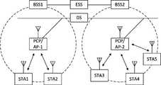
도 1은 본 발명의 일 실시예에 따른 무선랜 시스템을 도시하고 있다. 무선랜 시스템은 하나 또는 그 이상의 베이직 서비스 세트(Basic Service Set, BSS)를 포함하는데, BSS는 성공적으로 동기화를 이루어서 서로 통신할 수 있는 기기들의 집합을 나타낸다. 일반적으로 BSS는 인프라스트럭쳐 BSS(infrastructure BSS)와 독립 BSS(Independent BSS, IBSS)로 구분될 수 있으며, 도 1은 이 중 인프라스트럭쳐 BSS를 나타내고 있다.1 shows a wireless LAN system according to an embodiment of the present invention. A wireless LAN system includes one or more basic service sets (BSSs), which represent a set of devices capable of successfully synchronizing and communicating with each other. In general, the BSS can be divided into an infrastructure BSS (Infrastructure BSS) and an independent BSS (Independent BSS, IBSS), and FIG. 1 shows an infrastructure BSS among them.
도 1에 도시된 바와 같이 인프라스트럭쳐 BSS(BSS1, BSS2)는 하나 또는 그 이상의 스테이션(STA1, STA2, STA3, STA4, STA5), 분배 서비스(Distribution Service)를 제공하는 스테이션인 액세스 포인트(PCP/AP-1, PCP/AP-2), 및 다수의 액세스 포인트(PCP/AP-1, PCP/AP-2)를 연결시키는 분배 시스템(Distribution System, DS)을 포함한다.As shown in FIG. 1, the infrastructure BSS (BSS1, BSS2) is one or more stations (STA1, STA2, STA3, STA4, STA5), an access point (PCP / AP) that is a station that provides a distribution service. -1, PCP / AP-2), and a Distribution System (DS) that connects multiple access points (PCP / AP-1, PCP / AP-2).
스테이션(Station, STA)은 IEEE 802.11 표준의 규정을 따르는 매체 접속 제어(Medium Access Control, MAC)와 무선 매체에 대한 물리층(Physical Layer) 인터페이스를 포함하는 임의의 디바이스로서, 광의로는 비 액세스 포인트(non-AP) 스테이션뿐만 아니라 액세스 포인트(AP)를 모두 포함한다. 또한, 본 명세서에서 '단말'은 non-AP STA 또는 AP를 가리키거나, 양 자를 모두 가리키는 용어로 사용될 수 있다. 무선 통신을 위한 스테이션은 프로세서(Processor)와 송수신부(transmit/receive unit)를 포함하고, 실시예에 따라 유저 인터페이스부와 디스플레이 유닛 등을 더 포함할 수 있다. 프로세서는 무선 네트워크를 통해 전송할 프레임을 생성하거나 또는 상기 무선 네트워크를 통해 수신된 프레임을 처리하며, 그 밖에 스테이션을 제어하기 위한 다양한 처리를 수행할 수 있다. 그리고, 송수신부는 상기 프로세서와 기능적으로 연결되어 있으며 스테이션을 위하여 무선 네트워크를 통해 프레임을 송수신한다.A station (STA) is any device that includes a medium access control (MAC) and a physical layer interface to a wireless medium that conforms to the IEEE 802.11 standard. This includes both access points (APs) as well as non-AP stations. In addition, in this specification, 'terminal' may refer to a non-AP STA or an AP, or may be used as a term indicating both. The station for wireless communication includes a processor and a transmit / receive unit, and may further include a user interface and a display unit according to embodiments. The processor may generate a frame to be transmitted through a wireless network or process a frame received through the wireless network, and may also perform various processes for controlling a station. Then, the transceiver is functionally connected to the processor and transmits and receives frames through a wireless network for the station.
액세스 포인트(Access Point, AP)는 자신에게 결합된(associated) 스테이션을 위하여 무선 매체를 경유하여 분배시스템(DS)에 대한 접속을 제공하는 개체이다. 인프라스트럭쳐 BSS에서 비 AP 스테이션들 사이의 통신은 AP를 경유하여 이루어지는 것이 원칙이지만, 다이렉트 링크가 설정된 경우에는 비AP 스테이션들 사이에서도 직접 통신이 가능하다. 한편, 본 발명에서 AP는 PCP(Personal BSS Coordination Point)를 포함하는 개념으로 사용되며, 광의적으로는 집중 제어기, 기지국(Base Station, BS), 노드-B, BTS(Base Transceiver System), 또는 사이트 제어기 등의 개념을 모두 포함할 수 있다.An access point (AP) is an entity that provides access to a distribution system (DS) via a wireless medium for an associated station. In principle, communication between non-AP stations in the infrastructure BSS is performed through an AP, but when a direct link is established, direct communication between non-AP stations is also possible. On the other hand, in the present invention, the AP is used as a concept including a Personal BSS Coordination Point (PCP), and, broadly, a centralized controller, a base station (BS), a node-B, a base transceiver system (BTS), or a site. It can include all concepts such as a controller.
복수의 인프라스트럭쳐 BSS는 분배 시스템(DS)을 통해 상호 연결될 수 있다. 이때, 분배 시스템을 통하여 연결된 복수의 BSS를 확장 서비스 세트(Extended Service Set, ESS)라 한다.The plurality of infrastructure BSSs may be interconnected through a distribution system (DS). At this time, a plurality of BSS connected through a distribution system is called an extended service set (ESS).
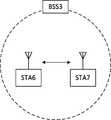
도 2는 본 발명의 다른 실시예에 따른 무선랜 시스템인 독립 BSS를 도시하고 있다. 도 2의 실시예에서 도 1의 실시예와 동일하거나 상응하는 부분은 중복적인 설명을 생략하도록 한다.2 illustrates an independent BSS that is a wireless LAN system according to another embodiment of the present invention. In the embodiment of FIG. 2, the same or corresponding parts as the embodiment of FIG. 1 will be omitted.
도 2에 도시된 BSS3는 독립 BSS이며 AP를 포함하지 않기 때문에, 모든 스테이션(STA6, STA7)이 AP와 접속되지 않은 상태이다. 독립 BSS는 분배 시스템으로의 접속이 허용되지 않으며, 자기 완비적 네트워크(self-contained network)를 이룬다. 독립 BSS에서 각각의 스테이션들(STA6, STA7)은 다이렉트로 서로 연결될 수 있다.Since BSS3 shown in FIG. 2 is an independent BSS and does not include an AP, all stations STA6 and STA7 are not connected to the AP. The independent BSS is not allowed to access the distribution system, and forms a self-contained network. In the independent BSS, each of the stations STA6 and STA7 can be directly connected to each other.
도 3은 본 발명의 일 실시예에 따른 스테이션(100)의 구성을 나타낸 블록도이다.3 is a block diagram showing the configuration of a
도시된 바와 같이, 본 발명의 실시예에 따른 스테이션(100)은 프로세서(110), 송수신부(120), 유저 인터페이스부(140), 디스플레이 유닛(150) 및 메모리(160)를 포함할 수 있다.As illustrated, the
먼저, 송수신부(120)는 무선랜 패킷 등의 무선 신호를 송수신 하며, 스테이션(100)에 내장되거나 외장으로 구비될 수 있다. 실시예에 따르면, 송수신부(120)는 서로 다른 주파수 밴드를 이용하는 적어도 하나의 송수신 모듈을 포함할 수 있다. 이를 테면, 상기 송수신부(120)는 2.4GHz, 5GHz 및 60GHz 등의 서로 다른 주파수 밴드의 송수신 모듈을 포함할 수 있다. 일 실시예에 따르면, 스테이션(100)은 6GHz 이상의 주파수 밴드를 이용하는 송수신 모듈과, 6GHz 이하의 주파수 밴드를 이용하는 송수신 모듈을 구비할 수 있다. 각각의 송수신 모듈은 해당 송수신 모듈이 지원하는 주파수 밴드의 무선랜 규격에 따라 AP 또는 외부 스테이션과 무선 통신을 수행할 수 있다. 송수신부(120)는 스테이션(100)의 성능 및 요구 사항에 따라 한 번에 하나의 송수신 모듈만을 동작시키거나 동시에 다수의 송수신 모듈을 함께 동작시킬 수 있다. 스테이션(100)이 복수의 송수신 모듈을 포함할 경우, 각 송수신 모듈은 각각 독립된 형태로 구비될 수도 있으며, 복수의 모듈이 하나의 칩으로 통합되어 구비될 수도 있다.First, the
다음으로, 유저 인터페이스부(140)는 스테이션(100)에 구비된 다양한 형태의 입/출력 수단을 포함한다. 즉, 유저 인터페이스부(140)는 다양한 입력 수단을 이용하여 유저의 입력을 수신할 수 있으며, 프로세서(110)는 수신된 유저 입력에 기초하여 스테이션(100)을 제어할 수 있다. 또한, 유저 인터페이스부(140)는 다양한 출력 수단을 이용하여 프로세서(110)의 명령에 기초한 출력을 수행할 수 있다.Next, the
다음으로, 디스플레이 유닛(150)은 디스플레이 화면에 이미지를 출력한다. 상기 디스플레이 유닛(150)은 프로세서(110)에 의해 실행되는 컨텐츠 또는 프로세서(110)의 제어 명령에 기초한 유저 인터페이스 등의 다양한 디스플레이 오브젝트를 출력할 수 있다. 또한, 메모리(160)는 스테이션(100)에서 사용되는 제어 프로그램 및 그에 따른 각종 데이터를 저장한다. 이러한 제어 프로그램에는 스테이션(100)이 AP 또는 외부 스테이션과 접속을 수행하는데 필요한 접속 프로그램이 포함될 수 있다.Next, the
본 발명의 프로세서(110)는 다양한 명령 또는 프로그램을 실행하고, 스테이션(100) 내부의 데이터를 프로세싱 할 수 있다. 또한, 상기 프로세서(110)는 상술한 스테이션(100)의 각 유닛들을 제어하며, 유닛들 간의 데이터 송수신을 제어할 수 있다. 본 발명의 실시예에 따르면, 프로세서(110)는 메모리(160)에 저장된 AP와의 접속을 위한 프로그램을 실행하고, AP가 전송한 통신 설정 메시지를 수신할 수 있다. 또한, 프로세서(110)는 통신 설정 메시지에 포함된 스테이션(100)의 우선 조건에 대한 정보를 판독하고, 스테이션(100)의 우선 조건에 대한 정보에 기초하여 AP에 대한 접속을 요청할 수 있다. 본 발명의 프로세서(110)는 스테이션(100)의 메인 컨트롤 유닛을 가리킬 수도 있으며, 실시예에 따라 스테이션(100)의 일부 구성 이를 테면, 송수신부(120)등을 개별적으로 제어하기 위한 컨트롤 유닛을 가리킬 수도 있다. 프로세서(110)는 본 발명의 실시예에 따른 스테이션(100)의 무선 신호 송수신의 각종 동작을 제어한다. 이에 대한 구체적인 실시예는 추후 기술하기로 한다.The
도 3에 도시된 스테이션(100)은 본 발명의 일 실시예에 따른 블록도로서, 분리하여 표시한 블록들은 디바이스의 엘리먼트들을 논리적으로 구별하여 도시한 것이다. 따라서 상술한 디바이스의 엘리먼트들은 디바이스의 설계에 따라 하나의 칩으로 또는 복수의 칩으로 장착될 수 있다. 이를테면, 상기 프로세서(110) 및 송수신부(120)는 하나의 칩으로 통합되어 구현될 수도 있으며 별도의 칩으로 구현될 수도 있다. 또한, 본 발명의 실시예에서 상기 스테이션(100)의 일부 구성들, 이를 테면 유저 인터페이스부(140) 및 디스플레이 유닛(150) 등은 스테이션(100)에 선택적으로 구비될 수 있다.The
도 4는 본 발명의 일 실시예에 따른 AP(200)의 구성을 나타낸 블록도이다.4 is a block diagram showing the configuration of the
도시된 바와 같이, 본 발명의 실시예에 따른 AP(200)는 프로세서(210), 송수신부(220) 및 메모리(260)를 포함할 수 있다. 도 4에서 AP(200)의 구성 중 도 3의 스테이션(100)의 구성과 동일하거나 상응하는 부분에 대해서는 중복적인 설명을 생략하도록 한다.As illustrated, the
도 4를 참조하면, 본 발명에 따른 AP(200)는 적어도 하나의 주파수 밴드에서 BSS를 운영하기 위한 송수신부(220)를 구비한다. 도 3의 실시예에서 전술한 바와 같이, 상기 AP(200)의 송수신부(220) 또한 서로 다른 주파수 밴드를 이용하는 복수의 송수신 모듈을 포함할 수 있다. 즉, 본 발명의 실시예에 따른 AP(200)는 서로 다른 주파수 밴드, 이를 테면 2.4GHz, 5GHz, 60GHz 중 두 개 이상의 송수신 모듈을 함께 구비할 수 있다. 바람직하게는, AP(200)는 6GHz 이상의 주파수 밴드를 이용하는 송수신 모듈과, 6GHz 이하의 주파수 밴드를 이용하는 송수신 모듈을 구비할 수 있다. 각각의 송수신 모듈은 해당 송수신 모듈이 지원하는 주파수 밴드의 무선랜 규격에 따라 스테이션과 무선 통신을 수행할 수 있다. 상기 송수신부(220)는 AP(200)의 성능 및 요구 사항에 따라 한 번에 하나의 송수신 모듈만을 동작시키거나 동시에 다수의 송수신 모듈을 함께 동작시킬 수 있다.Referring to FIG. 4, the
다음으로, 메모리(260)는 AP(200)에서 사용되는 제어 프로그램 및 그에 따른 각종 데이터를 저장한다. 이러한 제어 프로그램에는 스테이션의 접속을 관리하는 접속 프로그램이 포함될 수 있다. 또한, 프로세서(210)는 AP(200)의 각 유닛들을 제어하며, 유닛들 간의 데이터 송수신을 제어할 수 있다. 본 발명의 실시예에 따르면, 프로세서(210)는 메모리(260)에 저장된 스테이션과의 접속을 위한 프로그램을 실행하고, 하나 이상의 스테이션에 대한 통신 설정 메시지를 전송할 수 있다. 이때, 통신 설정 메시지에는 각 스테이션의 접속 우선 조건에 대한 정보가 포함될 수 있다. 또한, 프로세서(210)는 스테이션의 접속 요청에 따라 접속 설정을 수행한다. 프로세서(210)는 본 발명의 실시예에 따른 AP(200)의 무선 신호 송수신의 각종 동작을 제어한다. 이에 대한 구체적인 실시예는 추후 기술하기로 한다.Next, the
도 5는 STA가 AP와 링크를 설정하는 과정을 개략적으로 도시하고 있다.5 schematically illustrates a process in which an STA establishes a link with an AP.
도 5를 참조하면, STA(100)와 AP(200) 간의 링크는 크게 스캐닝(scanning), 인증(authentication) 및 결합(association)의 3단계를 통해 설정된다. 먼저, 스캐닝 단계는 AP(200)가 운영하는 BSS의 접속 정보를 STA(100)가 획득하는 단계이다. 스캐닝을 수행하기 위한 방법으로는 AP(200)가 주기적으로 전송하는 비콘(beacon) 메시지(S101)만을 활용하여 정보를 획득하는 패시브 스캐닝(passive scanning) 방법과, STA(100)가 AP에 프로브 요청(probe request)을 전송하고(S103), AP로부터 프로브 응답(probe response)을 수신하여(S105) 접속 정보를 획득하는 액티브 스캐닝(active scanning) 방법이 있다.Referring to FIG. 5, the link between the
스캐닝 단계에서 성공적으로 무선 접속 정보를 수신한 STA(100)는 인증 요청(authentication request)을 전송하고(S107a), AP(200)로부터 인증 응답(authentication response)을 수신하여(S107b) 인증 단계를 수행한다. 인증 단계가 수행된 후, STA(100)는 결합 요청(association request)를 전송하고(S109a), AP(200)로부터 결합 응답(association response)을 수신하여(S109b) 결합 단계를 수행한다.The
한편, 추가적으로 802.1X 기반의 인증 단계(S111) 및 DHCP를 통한 IP 주소 획득 단계(S113)가 수행될 수 있다. 도 5에서 인증 서버(300)는 STA(100)와 802.1X 기반의 인증을 처리하는 서버로서, AP(200)에 물리적으로 결합되어 존재하거나 별도의 서버로서 존재할 수 있다.Meanwhile, an 802.1X-based authentication step (S111) and an IP address acquisition step (S113) through DHCP may be performed. In FIG. 5, the
도 6은 무선랜 통신에서 사용되는 CSMA(Carrier Sense Multiple Access)/CA(Collision Avoidance) 방법을 나타내고 있다.6 shows a CSMA (Carrier Sense Multiple Access) / CA (Collision Avoidance) method used in wireless LAN communication.
무선랜 통신을 수행하는 단말은 데이터를 전송하기 전에 캐리어 센싱(Carrier Sensing)을 수행하여 채널이 점유 상태(busy)인지 여부를 체크한다. 만약, 일정한 세기 이상의 무선 신호가 감지되는 경우 해당 채널이 점유 상태(busy)인 것으로 판별되고, 상기 단말은 해당 채널에 대한 액세스를 지연한다. 이러한 과정을 클리어 채널 할당(Clear Channel Assessment, CCA) 이라고 하며, 해당 신호 감지 유무를 결정하는 레벨을 CCA 임계값(CCA threshold)이라 한다. 만약 단말에 수신된 CCA 임계값 이상의 무선 신호가 해당 단말을 수신자로 하는 경우, 단말은 수신된 무선 신호를 처리하게 된다. 한편, 해당 채널에서 무선 신호가 감지되지 않거나 CCA 임계값보다 작은 세기의 무선 신호가 감지될 경우 상기 채널은 유휴 상태(idle)인 것으로 판별된다.The terminal performing wireless LAN communication performs carrier sensing before transmitting data to check whether the channel is in a busy state. If a radio signal having a certain intensity or higher is detected, it is determined that the corresponding channel is in a busy state, and the terminal delays access to the corresponding channel. This process is called Clear Channel Assessment (CCA), and the level to determine whether or not the corresponding signal is detected is referred to as a CCA threshold. If the radio signal above the CCA threshold received by the terminal makes the corresponding terminal a receiver, the terminal processes the received radio signal. Meanwhile, when a radio signal is not detected in a corresponding channel or when a radio signal having a strength lower than a CCA threshold is detected, the channel is determined to be idle.
채널이 유휴 상태인 것으로 판별되면, 전송할 데이터가 있는 각 단말은 각 단말의 상황에 따른 IFS(InterFrame Space) 이를테면, AIFS(Arbitration IFS), PIFS(PCF IFS) 등의 시간 뒤에 백오프 절차를 수행한다. 실시예에 따라, 상기 AIFS는 기존의 DIFS(DCF IFS)를 대체하는 구성으로 사용될 수 있다. 각 단말은 해당 단말에 할당된 난수(random number) 만큼의 슬롯 타임을 상기 채널의 유휴 상태의 간격(interval) 동안 감소시켜가며 대기하고, 슬롯 타임을 모두 소진한 단말이 해당 채널에 대한 액세스를 시도하게 된다. 이와 같이 각 단말들이 백오프 절차를 수행하는 구간을 경쟁 윈도우 구간이라고 한다.When it is determined that the channel is in an idle state, each terminal having data to be transmitted performs a backoff procedure after a time such as interframe space (IFS), such as AIFS (Arbitration IFS), PIFS (PCF IFS) according to the situation of each terminal. . According to an embodiment, the AIFS may be used as a configuration to replace the existing DIFS (DCF IFS). Each terminal waits while reducing the slot time corresponding to a random number allocated to the corresponding terminal during an idle interval of the channel, and the terminal exhausting the slot time tries to access the channel Is done. In this way, a period in which each terminal performs a backoff procedure is called a contention window period.
만약, 특정 단말이 상기 채널에 성공적으로 액세스하게 되면, 해당 단말은 상기 채널을 통해 데이터를 전송할 수 있다. 그러나, 액세스를 시도한 단말이 다른 단말과 충돌하게 되면, 충돌된 단말들은 각각 새로운 난수를 할당 받아 다시 백오프 절차를 수행한다. 일 실시예에 따르면, 각 단말에 새로 할당되는 난수는 해당 단말이 이전에 할당 받은 난수 범위(경쟁 윈도우, CW)의 2배의 범위(2*CW) 내에서 결정될 수 있다. 한편, 각 단말은 다음 경쟁 윈도우 구간에서 다시 백오프 절차를 수행하여 액세스를 시도하며, 이때 각 단말은 이전 경쟁 윈도우 구간에서 남게 된 슬롯 타임부터 백오프 절차를 수행한다. 이와 같은 방법으로 무선랜 통신을 수행하는 각 단말들은 특정 채널에 대한 서로간의 충돌을 회피할 수 있다.If a specific terminal successfully accesses the channel, the corresponding terminal can transmit data through the channel. However, when the terminal attempting to access collides with another terminal, the collisiond terminals each receive a new random number and perform a backoff procedure again. According to an embodiment, the random number newly allocated to each terminal may be determined within a range (2 * CW) of twice the random number range (competition window, CW) previously allocated by the corresponding terminal. Meanwhile, each terminal attempts access by performing a backoff procedure again in the next contention window section, and each terminal performs a backoff procedure from the slot time remaining in the previous contention window section. In this way, each terminal performing wireless LAN communication can avoid collision with each other for a specific channel.
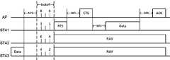
도 7은 RTS(Request to Send) 프레임과 CTS(Clear to Send) 프레임을 이용한 DCF(Distributed Coordination Function) 수행 방법을 나타낸 도면이다.7 is a diagram illustrating a method of performing a distributed coordination function (DCF) using a request to send (RTS) frame and a clear to send (CTS) frame.
BSS 내의 AP 및 STA들은 데이터를 전송하기 위한 권리를 얻기 위해 경쟁을 하게 된다. 이전 단계의 데이터 전송이 완료되면, 전송할 데이터가 있는 각 단말들은 AIFS의 시간이 지난 후에 각 단말에 할당된 난수의 백오프 카운터(또는, 백오프 타이머)를 감소해가며 백오프 절차를 수행한다. 백오프 카운터가 만료된 전송 단말은 RTS(Request to Send) 프레임을 전송하여, 해당 단말이 전송할 데이터가 있음을 알린다. 도 7의 실시예에 따르면, 최소의 백오프로 경쟁에서 우위를 점한 STA1이 백오프 카운터 만료 후 RTS 프레임을 전송할 수 있다. RTS 프레임은 리시버 어드레스(receiver address), 트랜스미터 어드레스(transmitter address) 및 듀레이션(duration) 등의 정보를 포함한다. RTS 프레임을 수신한 수신 단말(즉, 도 7에서 AP)은 SIFS(Short IFS)의 시간을 대기한 후 CTS(Clear to Send) 프레임을 전송하여 전송 단말(STA1)에게 데이터 전송이 가능함을 알린다. CTS 프레임은 리시버 어드레스와 듀레이션 등의 정보를 포함한다. 이때, CTS 프레임의 리시버 어드레스는 이에 대응하는 RTS 프레임의 트랜스미터 어드레스 즉, 전송 단말(STA1)의 어드레스와 동일하게 설정될 수 있다.APs and STAs in the BSS compete for the right to transmit data. When the data transmission of the previous step is completed, each terminal having data to be transmitted performs a backoff procedure by decreasing the backoff counter (or backoff timer) of the random number allocated to each terminal after the time of AIFS. The transmitting terminal whose backoff counter has expired transmits a Request to Send (RTS) frame to inform that the terminal has data to transmit. According to the embodiment of FIG. 7, STA1, which has an advantage in contention with minimum backoff, may transmit an RTS frame after the backoff counter expires. The RTS frame includes information such as a receiver address, a transmitter address, and a duration. After receiving the RTS frame, the receiving terminal (that is, the AP in FIG. 7) waits for a time of SIFS (Short IFS) and transmits a Clear to Send (CTS) frame to inform the transmitting terminal STA1 that data transmission is possible. The CTS frame includes information such as a receiver address and duration. At this time, the receiver address of the CTS frame may be set to be the same as the address of the transmitter of the corresponding RTS frame, that is, the address of the transmitting terminal STA1.
CTS 프레임을 수신한 전송 단말(STA1)은 SIFS의 시간 후에 데이터를 전송한다. 데이터 전송이 완료되면, 수신 단말(AP)은 SIFS의 시간 후에 응답(ACK) 프레임을 전송하여 데이터 전송이 완료되었음을 알린다. 기 설정된 시간 이내에 응답 프레임을 수신한 경우, 전송 단말은 데이터 전송에 성공한 것으로 간주한다. 그러나 기 설정된 시간 이내에 응답 프레임이 수신되지 않은 경우, 전송 단말은 데이터 전송에 실패한 것으로 간주한다. 한편, 상기 전송 과정 동안 RTS 프레임 및 CTS 프레임 중 적어도 하나를 수신한 주변 단말들은 NAV(Network Allocation Vector)를 설정하며, 설정된 NAV가 만료될 때까지 데이터 전송을 수행하지 않는다. 이때, 각 단말의 NAV는 수신된 RTS 프레임 또는 CTS 프레임의 듀레이션 필드에 기초하여 설정될 수 있다.The transmitting terminal STA1 receiving the CTS frame transmits data after the time of SIFS. When the data transmission is completed, the receiving terminal AP transmits an acknowledgment (ACK) frame after the time of SIFS to inform that the data transmission is completed. If a response frame is received within a preset time, the transmitting terminal is considered to have successfully transmitted data. However, if a response frame is not received within a preset time, the transmitting terminal is considered to have failed data transmission. Meanwhile, neighboring terminals that have received at least one of the RTS frame and the CTS frame during the transmission process set a Network Allocation Vector (NAV) and do not perform data transmission until the set NAV expires. At this time, the NAV of each terminal may be set based on the duration field of the received RTS frame or CTS frame.
전술한 데이터 전송 과정에서, 단말들의 RTS 프레임 또는 CTS 프레임이 간섭이나 충돌 등의 상황으로 목표 단말(즉, 리시버 어드레스의 단말)에게 정상적으로 전달되지 않는 경우에는 이후의 과정의 수행이 중단된다. RTS 프레임을 전송한 전송 단말(STA1)은 데이터 전송이 불가능한 것으로 간주하고, 새로운 난수를 할당 받아 다음 회의 경쟁에 참여하게 된다. 이때, 새로 할당되는 난수는 전술한 바와 같이 이전의 기 설정된 난수 범위(경쟁 윈도우, CW)의 2배의 범위(2*CW) 내에서 결정될 수 있다.In the above data transmission process, if the RTS frame or CTS frame of the terminals is not normally delivered to the target terminal (ie, the terminal of the receiver address) due to interference or collision, the execution of the subsequent process is stopped. The transmitting terminal STA1 that transmits the RTS frame considers that data transmission is impossible, and is assigned a new random number to participate in the next conference competition. At this time, the newly allocated random number may be determined within a range (2 * CW) twice as long as the previously set random number range (competition window, CW).
이하의 실시예들에서, 제1 단말이 제2 단말로 RTS 프레임을 전송한다는 것은, 별도의 설명이 없으면 트랜스미터 어드레스가 제1 단말의 어드레스이고, 리시버 어드레스가 제2 단말의 어드레스인 RTS 프레임을 제1 단말이 전송한다는 의미로 해석될 수 있다. 또한, 제1 단말이 제2 단말로 CTS 프레임을 전송한다는 것은, 별도의 설명이 없으면 리시버 어드레스가 제2 단말의 어드레스인 CTS 프레임을 제1 단말이 전송한다는 의미로 해석될 수 있다.In the following embodiments, when the first terminal transmits the RTS frame to the second terminal, the RTS frame whose transmitter address is the address of the first terminal and the receiver address is the address of the second terminal, unless otherwise specified. It can be interpreted as meaning that 1 terminal transmits. Further, that the first terminal transmits the CTS frame to the second terminal may be interpreted as meaning that the first terminal transmits the CTS frame whose receiver address is the address of the second terminal, unless otherwise specified.
한편, 전술한 바와 같은 경쟁 기반의 데이터 전송 방법들은 사용자가 적은 환경에서는 잘 동작할 수 있지만, 패킷을 전송하고자 하는 사용자가 많은 환경에서는 통신 성능이 급격히 열악해지는 문제가 있다. 따라서, 밀집된 사용자 환경에서 복수의 단말들이 효율적으로 데이터를 송수신하기 위한 방법이 필요하다. 이하, 각 도면을 참조로 본 발명의 실시예에 따른 데이터 송수신 방법을 설명한다. 각 도면의 실시예에서, 이전 도면의 실시예와 동일하거나 상응하는 부분은 중복적인 설명을 생략하도록 한다.On the other hand, the above-described contention-based data transmission methods may work well in an environment where there are few users, but there is a problem in that communication performance is rapidly deteriorated in an environment where there are many users who want to transmit packets. Accordingly, there is a need for a method for efficiently transmitting and receiving data by a plurality of terminals in a dense user environment. Hereinafter, a data transmission / reception method according to an embodiment of the present invention will be described with reference to each drawing. In each embodiment of the drawings, the same or corresponding parts as the embodiments of the previous drawings will be omitted.
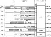
도 8 내지 도 10은 본 발명의 일 실시예로서, 분산 접속 그룹을 이용한 단말의 무선 통신 방법을 나타내고 있다. 본 발명의 일 실시예에 따르면, BSS 내의 복수의 단말들은 적어도 하나의 그룹으로 그룹핑(grouping)되며, 할당된 그룹 단위로 단말들의 데이터 송수신이 수행될 수 있다.8 to 10 is an embodiment of the present invention, and shows a wireless communication method of a terminal using a distributed access group. According to an embodiment of the present invention, a plurality of terminals in the BSS are grouped into at least one group, and data transmission / reception of the terminals can be performed in units of assigned groups.
그룹 단위의 데이터 송수신을 위해, AP는 분산 접속 그룹 파라메터를 전송한다. AP로부터 분산 접속 그룹 파라메터를 수신한 BSS 내의 단말들은 그룹 단위의 분산 접속을 개시한다. 그룹 단위의 분산 접속을 트리거(trigger)하는 분산 접속 그룹 파라메터는 접속 지연 임계값에 기초하여 전송될 수 있다. AP는 BSS 내의 단말들이 패킷을 전송하기 위해 CSMA/CA 경쟁을 하는데 걸리는 시간이 접속 지연 임계값보다 높을 경우 분산 접속 그룹 파라메터를 전송할 수 있다. 예를 들어, AP는 해당 AP 또는 BSS 내의 단말에 할당되는 경쟁 윈도우 값이 접속 지연 임계값보다 높을 경우 분산 접속 그룹 파라메터를 전송할 수 있다. 다른 실시예로서, AP는 단위 시간당 패킷 충돌 횟수 정보를 획득하고, 상기 패킷 충돌 횟수가 기 설정된 기준값보다 높을 경우 분산 접속 그룹 파라메터를 전송할 수 있다.To transmit / receive group data, the AP transmits distributed access group parameters. The terminals in the BSS receiving the distributed access group parameter from the AP initiate distributed access in groups. The distributed access group parameter that triggers distributed access in group units may be transmitted based on a connection delay threshold. The AP may transmit distributed access group parameters when the time taken for the terminals in the BSS to compete for CSMA / CA to transmit packets is higher than the access delay threshold. For example, the AP may transmit the distributed access group parameter when the contention window value allocated to the terminal in the corresponding AP or BSS is higher than the access delay threshold. As another embodiment, the AP may acquire information on the number of packet collisions per unit time, and transmit the distributed access group parameter when the number of packet collisions is higher than a preset reference value.
분산 접속 그룹 파라메터는 비콘(beacon), 프로브 응답(probe response), 결합 응답(association response) 등의 제어 메시지에 포함될 수 있다. 다른 실시예에 따르면, AP는 분산 접속 그룹 파라메터를 별도의 트리거 프레임을 통해 전송할 수 있다. 분산 접속 그룹 파라메터는 단말들이 그룹 단위의 분산 접속을 수행하기 위해 참조하는 파라메터로서, 해당 BSS에 부여된 그룹 개수, 그룹간 접속 오프셋(inter group access offset) 등의 정보를 포함한다. 이때, 각 그룹에 포함되는 단말들의 정보는 분산 접속 그룹 파라메터를 통해 지정된다. AP는 각 그룹에 속하는 단말들을 직접 지정하고, 상기 지정 정보를 분산 접속 그룹 파라메터로 전송할 수 있다. 다른 실시예에 따르면 단말은 AP로부터 수신된 분산 접속 그룹 파라메터를 이용하여 해당 단말에 할당될 그룹 정보 즉, 그룹 번호를 획득할 수 있다.The distributed access group parameters may be included in control messages such as beacons, probe responses, and association responses. According to another embodiment, the AP may transmit distributed access group parameters through a separate trigger frame. The distributed access group parameter is a parameter that UEs refer to in order to perform distributed access in groups, and includes information such as the number of groups assigned to the corresponding BSS and inter group access offset. At this time, information of terminals included in each group is designated through distributed access group parameters. The AP may directly designate terminals belonging to each group, and transmit the designated information as a distributed access group parameter. According to another embodiment, the terminal may acquire group information to be allocated to the corresponding terminal, that is, a group number using the distributed access group parameter received from the AP.
단말의 그룹 번호는 해당 단말의 식별자 정보(또는, 주소 정보)와 그룹 개수 정보에 기초하여 결정될 수 있다. 일 실시예에 따르면, 단말의 그룹 번호는 아래 수학식과 같이 해당 단말의 식별자 정보를 그룹 개수 정보로 모듈로(modulo) 연산한 결과 값에 기초하여 결정될 수 있다.The group number of the terminal may be determined based on identifier information (or address information) of the terminal and group number information. According to an embodiment, the group number of the terminal may be determined based on a result of modulo calculation of identifier information of the corresponding terminal as group number information, as shown in the following equation.

이때, 단말의 식별자 정보로는 해당 단말의 MAC 주소, 결합 ID(Association Identification, AID) 정보 등이 사용될 수 있다. 48bit의 MAC 주소가 단말의 식별자 정보로 사용되는 경우를 예로 들면, 3C-A9-F4-69-43-A4의 MAC 주소는 이진수로 0011 1100 1010 1001 1111 0100 0110 1001 0100 0011 1010 0100으로 표현된다. 만약, 그룹 개수가 5인 경우 상기 MAC 주소를 5로 모듈로(modulo) 연산하면 4를 결과값으로 획득하게 된다. 이때, 모듈로 연산의 결과값인 4가 해당 단말의 그룹 번호로 할당 되거나, 수학식 1과 같이 모듈로 연산의 결과값에 1을 더한 값(즉, 5)이 해당 단말의 그룹 번호로 할당 될 수 있다.In this case, as the identifier information of the terminal, the MAC address of the terminal, association identification (AID) information, and the like may be used. For example, when the 48-bit MAC address is used as the identifier information of the terminal, the MAC address of 3C-A9-F4-69-43-A4 is represented as 0011 1100 1010 1001 1111 0100 0110 1001 0100 0011 1010 0100 in binary. If the number of groups is 5, when the MAC address is modulo 5, 4 is obtained as a result. At this time, 4, which is the result of the modulo operation, is assigned as a group number of the corresponding terminal, or a value obtained by adding 1 to the result of the modulo operation as shown in Equation 1 (ie, 5) is assigned as the group number of the corresponding terminal You can.
이와 같이 복수의 단말들이 적어도 하나의 그룹으로 분류되면, 각 단말들은 할당된 그룹 단위로 데이터 송수신을 수행한다. 본 발명의 실시예에 따르면, 각 그룹의 접속 기간(access period) 동안, 해당 그룹에 지정된 단말들만 데이터 송수신에 참여할 수 있다. 이때, 동일 그룹 내의 각 단말들은 순차적으로 데이터를 송수신할 수도 있고, 서로 다른 채널(주파수 대역)을 이용하여 동시에 데이터를 송수신할 수도 있다. 각 단말이 순차적으로 데이터를 송수신할 경우, 각 단말은 해당 그룹의 접속 기간 동안 전술한 CSMA/CA 방법을 이용하여 상향(uplink) 데이터를 전송할 수 있다. 또한, 각 단말이 서로 다른 채널을 이용하여 동시에 데이터를 송수신할 경우, 각 단말은 OFDMA(Orthogonal Frequency Domain Multiple Access)를 이용하여 상향 데이터를 전송할 수 있다.As described above, when a plurality of terminals are classified into at least one group, each terminal performs data transmission / reception in an assigned group unit. According to an embodiment of the present invention, during the access period of each group, only terminals designated in the corresponding group can participate in data transmission and reception. At this time, each terminal in the same group may sequentially transmit and receive data, or may transmit and receive data simultaneously using different channels (frequency bands). When each terminal sequentially transmits and receives data, each terminal may transmit uplink data using the above-described CSMA / CA method during the access period of the corresponding group. In addition, when each terminal transmits and receives data simultaneously using different channels, each terminal may transmit uplink data using Orthogonal Frequency Domain Multiple Access (OFDMA).
본 발명의 일 실시예에 따르면, 각 그룹의 접속 기간은 그룹간 접속 오프셋(inter group access offset) 시간 동안 채널이 유휴(idle)할 때까지 지속될 수 있다. 즉, 기 설정된 그룹간 접속 오프셋 시간 동안 채널이 유휴 하면, 이전 그룹의 접속 기간에서 다음 그룹의 접속 기간으로 전환된다. 한편 본 발명의 다른 실시예에 따르면, 각 그룹의 접속 기간은 고정된 시간 값으로 설정될 수도 있으며, 그룹 내에 지정된 단말들의 개수 정보 등에 기초하여 가변 하는 시간 값으로 설정될 수도 있다.According to an embodiment of the present invention, the access period of each group may last until the channel is idle for an inter group access offset time. That is, when the channel is idle for a preset connection offset time between groups, the channel is switched from the previous group access period to the next group access period. Meanwhile, according to another embodiment of the present invention, the access period of each group may be set to a fixed time value, or may be set to a variable time value based on information on the number of terminals designated in the group.
도 8은 분산 접속 그룹을 이용한 단말의 무선 통신 방법의 일 실시예를 나타내고 있다. 도 8의 실시예에서, 데이터 전송을 위한 STA는 6개이며 그룹 개수는 3으로 설정된다. 또한 전술한 그룹 번호 결정 방법에 기초하여, STA1 및 STA2는 그룹 1으로, STA3 및 STA4는 그룹 2로, STA5 및 STA6는 그룹 3로 각각 그룹핑 된다고 가정한다. 각 단말들은 그룹 별로 할당된 접속 순서에 따라 데이터 송수신을 수행한다. 도 8의 실시예에서는 그룹 1, 그룹 2, 그룹 3의 순서대로 접속 순서가 할당되며, 그룹 1의 단말들이 가장 먼저 접속을 시도한다.8 shows an embodiment of a wireless communication method of a terminal using a distributed access group. In the embodiment of FIG. 8, there are 6 STAs for data transmission and the number of groups is set to 3. Also, based on the above-described group number determination method, it is assumed that STA1 and STA2 are grouped into
그룹 1에 포함된 STA1 및 STA2는 그룹 1의 접속 기간 동안 전술한 CSMA/CA 또는 OFDMA를 이용하여 상향(uplink) 데이터를 전송한다. 본 발명의 일 실시예에 따르면, 특정 그룹에 할당된 접속 기간 동안 해당 그룹에 속한 non-AP STA들의 상향 데이터 전송은 각각 기 설정된 횟수(이를테면, 1회)로 제한될 수 있다. 이때, 각 non-AP STA들은 상기 접속 기간 동안 순차적으로 상향 데이터를 전송할 수도 있고, 서로 다른 채널(주파수 대역)을 이용하여 동시에 상향 데이터를 전송할 수도 있다. 그러나 AP는 어느 그룹의 접속 기간에서도 하향(downlink) 데이터를 전송할 수 있으며, 특정 그룹에 할당된 접속 기간 내에서도 횟수의 제한 없이 하향 데이터를 전송할 수 있다.STA1 and STA2 included in the
이전 그룹(그룹 1) 단말들의 데이터 전송이 완료되면, 더 이상의 데이터 전송이 수행되지 않아 채널은 유휴(idle) 하게 된다. BSS 내의 각 단말들은 CCA를 수행하여 채널의 점유(busy) 여부를 확인하며, 채널의 유휴(idle) 상태가 그룹간 접속 오프셋 시간 동안 지속되면 다음 접속 순서 그룹(그룹 2)의 접속 기간이 시작된다. 즉, 그룹간 접속 오프셋 시간 동안 채널이 유휴(idle) 하면, 다음 그룹(그룹 2)의 단말들은 이전 그룹(그룹 1)의 접속 기간이 종료된 것으로 간주하고 해당 오프셋 시간 후에 바로 데이터 전송을 시도할 수 있다. 본 발명의 실시예에 따르면, 그룹간 접속 오프셋은 일반적인 백오프 절차의 수행을 위한 AIFS의 값보다 크게 설정될 수 있다. 일 실시예에 따르면, 그룹간 접속 오프셋은 AIFS의 2배 또는 3배의 값으로 설정될 수 있다. 다른 실시예에 따르면, 그룹간 접속 오프셋은 DIFS + a*CWmax 값으로 설정될 수 있다. 여기서, CWmax는 경쟁 윈도우의 최대값이며, a는 1 이하의 상수이다. 상수 a는 채널 가용 상황에 따라 기 설정된 범위에서 변경될 수 있다. BSS 내의 각 단말들은 그룹간 접속 오프셋이 발생할 경우(즉, 그룹간 접속 오프셋 시간 동안 채널이 유휴 할 경우), 데이터 송수신을 수행하는 그룹이 전환되었음을 식별할 수 있다.When the data transmission of the previous group (group 1) terminals is completed, no more data transmission is performed, and the channel is idle. Each terminal in the BSS performs CCA to check whether the channel is occupied or not, and if the idle state of the channel continues for a connection offset time between groups, the access period of the next access sequence group (Group 2) starts. . That is, if the channel is idle during the access offset time between groups, the terminals of the next group (group 2) consider that the access period of the previous group (group 1) is over and attempt to transmit data immediately after the offset time. You can. According to an embodiment of the present invention, the inter-group connection offset may be set larger than the value of AIFS for performing a normal back-off procedure. According to an embodiment, the connection offset between groups may be set to a value of 2 or 3 times AIFS. According to another embodiment, the connection offset between groups may be set as a value of DIFS + a * CWmax. Here, CWmax is the maximum value of the contention window, and a is a constant of 1 or less. The constant a can be changed in a preset range according to the channel availability. Each terminal in the BSS can identify that a group performing data transmission / reception is switched when a connection offset between groups occurs (that is, a channel is idle during a connection offset time between groups).
한편, 그룹간 접속 오프셋 시간이 짧게 설정될 경우(이를 테면, AIFS 등), 이전 그룹(그룹 1)의 접속 기간이 종료될 때까지 해당 그룹(그룹 1)에 속한 단말의 데이터 전송이 완료되지 않을 수 있다. 이때, 해당 단말은 다음 그룹(그룹 2)의 접속 기간에서도 상향 데이터 전송 경쟁에 참여할 수 있다. 즉, 각 단말에 할당된 그룹의 접속 기간에 백오프 절차를 개시하게 된 단말은 데이터 전송이 완료될 때까지 그룹별 접속 기간에 관계없이 백오프 절차를 계속 수행하여 데이터 전송을 시도할 수 있다.On the other hand, when the connection offset time between groups is set to be short (for example, AIFS, etc.), data transmission of the terminals belonging to the group (group 1) may not be completed until the access period of the previous group (group 1) ends. You can. At this time, the terminal can participate in uplink data transmission competition even in the access period of the next group (group 2). That is, the terminal that initiates the backoff procedure in the access period of the group assigned to each terminal may attempt to transmit data by continuously performing the backoff procedure regardless of the access period for each group until data transmission is completed.
도 8의 실시예에서 그룹 2의 접속 기간이 종료되면, 동일한 방법으로 그룹간 접속 오프셋 시간 후에 그룹 3의 접속 기간이 시작된다. 그룹 단위의 데이터 송수신은 각 그룹별로 1회씩 수행될 수도 있으며, 복수 회 반복될 수도 있다. 그룹 단위의 데이터 송수신이 복수 회 반복될 경우, 마지막 그룹(그룹 3)의 접속 기간이 종료되면 다시 처음 그룹(그룹 1)의 접속 기간이 재개될 수 있다. 이때, 그룹 단위의 데이터 송수신의 반복 횟수 정보는 분산 접속 그룹 파라메터에 포함될 수 있다.In the embodiment of FIG. 8, when the connection period of the
도 9는 분산 접속 그룹을 이용한 단말의 무선 통신 방법의 다른 실시예를 나타내고 있다. 본 발명의 다른 실시예에 따르면, 그룹 단위의 데이터 송수신의 수행 중에 분산 접속 그룹 파라메터의 적어도 하나의 정보가 변경될 수 있다. 도 9의 실시예에 따르면, 분산 접속 그룹 파라메터의 그룹 개수 정보가 변경될 수 있다. AP는 기 설정된 규칙에 따라 그룹 개수(# of Group) 초기값을 설정하고, 그룹 단위의 데이터 송수신 상황에 따라 그룹 개수를 변경할 수 있다.9 shows another embodiment of a wireless communication method of a terminal using a distributed access group. According to another embodiment of the present invention, at least one information of a distributed access group parameter may be changed during data transmission / reception of a group unit. According to the embodiment of FIG. 9, group number information of the distributed access group parameter may be changed. The AP may set the initial number of groups (# of Group) according to a preset rule, and change the number of groups according to the data transmission / reception status of the group unit.
도 9를 참조하면, AP는 그룹 개수의 초기값을 2로 설정하여 분산 접속 그룹 파라메터를 전송한다. 따라서, BSS 내의 단말들은 전술한 실시예에 따라 2개의 그룹으로 분류되고, 그룹 별로 할당된 접속 순서에 따라 그룹 1의 단말들부터 접속을 시도한다. 그러나 하나의 그룹에 많은 수의 단말들이 할당되면, 해당 그룹의 단말들이 모두 데이터 전송을 완료하는데 소요되는 시간이 길어지고, 해당 그룹의 접속 기간 동안 단말들 간에 충돌이 발생할 확률도 높아진다. 따라서, AP는 그룹 단위의 분산 접속에 사용되는 그룹 개수를 늘려서 동일 시간대(즉, 접속 기간)에 경쟁에 참여하는 단말의 개수를 줄일 수 있다.Referring to FIG. 9, the AP transmits a distributed access group parameter by setting the initial value of the number of groups to 2. Accordingly, the terminals in the BSS are classified into two groups according to the above-described embodiment, and attempts to access from the terminals of
일 실시예에 따르면, AP는 개별 그룹의 접속 기간의 지속 시간(duration)에 기초하여 그룹 개수를 변경할 수 있다. 즉, AP는 해당 그룹의 단말들이 데이터 전송 경쟁을 시작한 때부터 그룹간 접속 오프셋이 발생할 때까지의 시간이 기 설정된 최대 경쟁 시간 임계값 보다 길어질 경우 그룹 개수를 증가시킬 수 있다. 그룹 개수가 증가될 경우, 갱신된 그룹 개수는 이전 그룹 개수에서 1씩 증가되거나, 이전 그룹 개수의 2배로 증가될 수 있으며, 본 발명은 이에 한정하지 않는다. AP는 갱신된 그룹 개수 정보를 분산 접속 그룹 파라메터를 통해 전송하며, 상기 분산 접속 그룹 파라메터를 수신한 각 단말들은 갱신된 그룹 개수 정보에 기초하여 해당 단말의 그룹 번호를 새로 획득한다. 도 9의 실시예에 따르면, AP는 그룹 개수를 초기값 2에서 4로 증가시키며, 갱신된 그룹 개수 정보가 포함된 분산 접속 그룹 파라메터를 비콘 또는 프로브 응답을 통해 BSS 내의 각 단말들로 전송한다. 각 단말들은 해당 단말의 그룹 번호를 변경하고, 갱신된 그룹 개수 정보 및 변경된 그룹 번호에 기초하여 그룹 단위의 데이터 송수신을 재개하게 된다.According to an embodiment, the AP may change the number of groups based on the duration of the access period of the individual group. That is, the AP may increase the number of groups when the time from when the UEs of the corresponding group starts data transmission contention to when the inter-group access offset occurs is longer than the preset maximum contention time threshold. When the number of groups is increased, the updated number of groups may be increased by 1 from the previous number of groups, or may be increased to twice the number of previous groups, and the present invention is not limited thereto. The AP transmits the updated group number information through the distributed access group parameter, and each terminal receiving the distributed access group parameter acquires a new group number of the corresponding terminal based on the updated group number information. According to the embodiment of FIG. 9, the AP increases the number of groups from an initial value of 2 to 4, and transmits a distributed access group parameter including updated group number information to each terminal in the BSS through a beacon or probe response. Each terminal changes the group number of the corresponding terminal and resumes data transmission and reception in group units based on the updated group number information and the changed group number.
반대로, AP는 해당 그룹의 단말들이 데이터 전송 경쟁을 시작한 때부터 그룹간 접속 오프셋이 발생할 때까지의 시간(즉, 개별 그룹의 접속 시간)이 기 설정된 최소 경쟁 시간 임계값 보다 짧을 경우 그룹 개수를 감소시킬 수 있다. 그룹 개수가 감소될 경우, 갱신된 그룹 개수는 이전 그룹 개수에서 1씩 감소되거나, 이전 그룹 개수의 절반으로 감소될 수 있으며, 본 발명은 이에 한정하지 않는다. 따라서, AP는 전체 단말 개수에 비해 과도한 그룹 개수로 인해, 그룹간 접속 오프셋의 발생 횟수가 증가되고 채널의 사용 효율이 저하되는 것을 방지할 수 있다.Conversely, the AP decreases the number of groups when the time from when the UEs of the corresponding group starts data transmission contention to the access offset between groups occurs (that is, the access time of individual groups) is shorter than a preset minimum contention time threshold. I can do it. When the number of groups is reduced, the updated number of groups may be decreased by 1 from the number of previous groups, or may be reduced to half of the number of previous groups, and the present invention is not limited thereto. Accordingly, the AP can prevent an increase in the number of occurrences of access offsets between groups and a decrease in channel usage efficiency due to an excessive number of groups compared to the total number of terminals.
도 10은 분산 접속 그룹을 이용한 단말의 무선 통신 방법의 또 다른 실시예를 나타내고 있다. 도 10의 실시예에 따르면, 분산 접속 그룹 파라메터는 각 그룹의 접속 시작 오프셋 정보를 더 포함할 수 있다. 접속 시작 오프셋 정보는 분산 접속 그룹 파라메터의 전송 이후 해당 그룹의 단말들이 접속을 시작하는 시점까지의 시간을 나타낸다. 각 단말은 해당 단말의 그룹 번호와 이에 대응하는 접속 시작 오프셋 정보를 획득할 수 있으며, 분산 접속 그룹 파라메터에 의해 트리거 된 시점으로부터 해당 단말의 접속 시작 오프셋 시간이 지난 후에 상향(uplink) 데이터 전송을 시작한다.10 shows another embodiment of a wireless communication method of a terminal using a distributed access group. According to the embodiment of FIG. 10, the distributed access group parameter may further include access start offset information of each group. The access start offset information indicates the time from the transmission of the distributed access group parameter until the terminals of the corresponding group start access. Each terminal can obtain the group number of the corresponding terminal and the corresponding connection start offset information, and start uplink data transmission after the connection start offset time of the corresponding terminal has elapsed from the time triggered by the distributed access group parameter. do.
도 10을 참조하면, 그룹 개수는 3으로 설정되며 그룹 1, 그룹 2 및 그룹 3의 단말들은 각각 제1 전송 시작 오프셋(Offset 1), 제2 전송 시작 오프셋(Offset 2) 및 제3 전송 시작 오프셋(Offset 3)의 시간이 지난 후에 데이터 전송을 시작한다. 일 실시예에 따르면, 각 그룹 간의 전송 시작 오프셋은 균일한 간격으로 설정될 수도 있으며, 각 그룹에 할당된 단말 개수 등에 따라 서로 다른 간격으로 설정될 수도 있다. 만약 각 그룹 간의 전송 시작 오프셋이 균일한 간격으로 설정될 경우 즉, 각 그룹에 할당된 접속 시간이 동일할 경우, 분산 접속 그룹 파라메터는 그룹 접속 시간(Group Access Time) 정보 T_gr을 포함할 수 있다. 그룹 접속 시간 정보(T_gr)를 획득한 각 단말은 해당 단말의 그룹 번호와 상기 그룹 접속 시간 정보(T_gr)를 이용하여 해당 단말이 속한 그룹의 전송 시작 오프셋 정보를 산출할 수 있다. 예를 들어, 도 10의 실시예에서 그룹 3의 전송 시작 오프셋(Offset)은 2*T_gr + Offset 1으로 결정될 수 있다. 여기서, Offset 1은 분산 접속 그룹 파라메터에 의해 트리거 된 시점으로부터 처음 그룹(그룹 1)의 접속 기간이 시작되기까지의 시간을 나타낸다.Referring to FIG. 10, the number of groups is set to 3, and UEs of
전술한 바와 같이, 이전 그룹의 단말의 데이터 전송이 완료되지 않았는데 다음 그룹의 전송 시작 오프셋 시간이 도래하여 다음 그룹의 단말들의 데이터 전송이 시작될 수 있다. 이때, 이전 그룹의 상기 데이터 전송이 완료되지 않은 단말은 다음 그룹의 접속 기간에서도 데이터 전송을 위한 경쟁에 참여할 수 있다.As described above, although the data transmission of the terminal of the previous group is not completed, the transmission start offset time of the next group has arrived and data transmission of the terminals of the next group may start. At this time, the terminal in which the data transmission of the previous group has not been completed may participate in the competition for data transmission even in the access period of the next group.
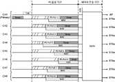
도 11은 본 발명의 다른 실시예로서, 전력 절약 모드에서 TIM 및 PS-Poll을 이용한 데이터 전송 방법을 나타내고 있다. 무선랜 단말들은 효율적인 전력 관리를 위해 전력 절약(Power Save, PS) 모드로 전환할 수 있다. PS 모드에서 각 단말(STA)은 AP가 주기적으로 전송하는 TIM(Traffic Indicator Map)을 수신하고, 해당 단말이 수신할 데이터가 있는지 여부를 확인한다. 만약 TIM이 해당 단말이 수신할 데이터가 있음을 지시할 경우, 상기 단말은 PS-Poll을 전송하여 데이터 수신이 가능함을 나타낸다. 이때, 단말은 전술한 CSMA/CA 방법을 이용하여 PS-Poll을 전송한다. 즉, PS-Poll을 전송하기 위한 각 단말은 경쟁 윈도우 구간에서 백오프 절차를 수행한다. 백오프 카운터가 만료된 단말은 PS-Poll을 전송하고, PS-Poll을 수신한 AP는 해당 단말로 데이터를 전송한다. 단말은 데이터 수신 완료 후 응답(ACK) 프레임을 전송하고, 수면(sleep) 상태로 전환한다.11 shows another embodiment of the present invention, and shows a data transmission method using TIM and PS-Poll in a power saving mode. WLAN terminals can be switched to a power save (PS) mode for efficient power management. In the PS mode, each terminal (STA) receives a traffic indicator map (TIM) periodically transmitted by the AP, and checks whether there is data to be received by the terminal. If the TIM indicates that the corresponding terminal has data to be received, the terminal indicates that data reception is possible by transmitting the PS-Poll. At this time, the terminal transmits the PS-Poll using the CSMA / CA method described above. That is, each terminal for transmitting the PS-Poll performs a backoff procedure in the contention window section. The terminal whose backoff counter has expired transmits the PS-Poll, and the AP receiving the PS-Poll transmits data to the corresponding terminal. After the data reception is completed, the terminal transmits an ACK frame and switches to a sleep state.
도 12는 PS-Poll의 프레임 구조를 나타내고 있다. 단말이 전송하는 PS-Poll에는 해당 단말의 결합 ID(AID), BSS 식별자(BSSID) 및 전송자 주소(Transmitter Address, TA)가 포함된다. 결합 ID는 단말의 결합 절차 중에 AP로부터 수신되며, 일 실시예에 따르면 최대 2007의 값을 가질 수 있다. BSS 식별자는 해당 단말이 결합된 AP의 MAC 주소를 나타내며, PS-Poll의 수신자 주소(Receiver Address, RA)로 사용된다. 전송자 주소는 PS-Poll을 전송하는 단말의 MAC 주소를 나타낸다.12 shows the frame structure of PS-Poll. The PS-Poll transmitted by the terminal includes a combination ID (AID), a BSS identifier (BSSID), and a transmitter address (TA) of the corresponding terminal. The association ID is received from the AP during the association procedure of the terminal, and may have a maximum value of 2007 according to an embodiment. The BSS identifier indicates the MAC address of the AP to which the corresponding terminal is coupled, and is used as a recipient address (RA) of the PS-Poll. The sender address indicates the MAC address of the terminal transmitting the PS-Poll.
본 발명의 실시예에 따르면, TIM 및 PS-Poll을 이용하여 다중 사용자를 위한 데이터 전송을 수행할 수 있다. 더욱 구체적으로, 본 발명의 실시예에 따르면 다중 채널을 이용한 데이터 분산 전송을 통해 복수의 단말들을 위한 효율적인 데이터 송수신을 수행할 수 있으며, 이때 TIM 및 PS-Poll이 이용될 수 있다. 이하의 실시예들은 단말들의 PS 모드에서 수행될 수 있지만, 본 발명은 이에 한정하지 아니하며 단말들의 다른 일반 모드에서도 수행될 수 있다. 본 발명이 단말들의 일반 모드에서 수행될 경우, 이하의 실시예에서 TIM, PS-Poll 및 PS 폴링 기간(period)은 각각 트리거 프레임, 데이터 요청 프레임 및 데이터 요청 프레임 전송 기간으로 대체될 수 있다.According to an embodiment of the present invention, data transmission for multiple users can be performed using TIM and PS-Poll. More specifically, according to an embodiment of the present invention, it is possible to perform efficient data transmission and reception for a plurality of terminals through data distribution transmission using multiple channels, where TIM and PS-Poll can be used. The following embodiments may be performed in the PS mode of the terminals, but the present invention is not limited to this and may be performed in other general modes of the terminals. When the present invention is performed in the normal mode of the terminals, in the following embodiments, the TIM, PS-Poll, and PS polling periods may be replaced with trigger frames, data request frames, and data request frame transmission periods, respectively.
도 13은 다중 채널을 이용한 데이터 분산 전송 방법의 일 실시예를 나타내고 있다. 도 13을 참조하면, PS 모드에 있는 단말들은 TIM이 전송되는 시점에 깨어나 TIM을 수신한다. 본 발명의 실시예에서, TIM은 다중 채널을 통해 각 단말들로 전송될 하향 데이터를 지시하는 트리거 프레임을 나타내며, 이러한 트리거 프레임은 실시예에 따라 TIM이 아닌 다른 형태의 프레임으로 구현될 수도 있다. TIM이 해당 단말로 전송될 데이터가 있음을 지시할 경우, 단말은 데이터를 수신하기 위해 해당 단말의 존재를 나타내는 PS-Poll을 전송한다. 한편, PS-Poll을 전송하기 위해서 단말은 백오프 절차를 통한 경쟁을 수행하는데, 많은 수의 단말들이 경쟁에 참여할 경우 충돌이 발생하여 성공적인 PS-Poll 전송까지 오랜 시간 경쟁이 지속될 확률이 높아진다.13 shows an embodiment of a data distribution transmission method using multiple channels. Referring to FIG. 13, terminals in the PS mode wake up at a time when the TIM is transmitted and receive the TIM. In an embodiment of the present invention, the TIM represents a trigger frame indicating downlink data to be transmitted to each terminal through multiple channels, and the trigger frame may be implemented as a frame other than the TIM according to the embodiment. When the TIM indicates that there is data to be transmitted to the corresponding terminal, the terminal transmits a PS-Poll indicating the existence of the corresponding terminal to receive the data. On the other hand, in order to transmit the PS-Poll, the UE performs competition through a back-off procedure. When a large number of UEs participate in the competition, a collision occurs, so that the probability of long-time competition until the successful PS-Poll transmission increases.
따라서, 본 발명의 실시예에 따르면 다중 채널을 이용하여 복수의 단말들의 PS-Poll이 전송될 수 있다. 본 발명의 실시예에서 PS-Poll은 상기 트리거 프레임에 대응하는 데이터 요청 프레임을 나타내며, 이러한 데이터 요청 프레임은 실시예에 따라 PS-Poll이 아닌 다른 형태의 프레임(이를테면, 후술하는 PS-Poll')으로도 구현될 수 있다.Accordingly, according to an embodiment of the present invention, PS-Polls of a plurality of terminals may be transmitted using multiple channels. In the exemplary embodiment of the present invention, PS-Poll indicates a data request frame corresponding to the trigger frame, and the data request frame is a frame other than PS-Poll according to an embodiment (for example, PS-Poll 'described later) Can also be implemented as
일 실시예에 따르면, 각 단말이 PS-Poll을 전송할 대상 채널은 해당 단말의 식별자 및 가용 채널 개수 정보에 기초하여 결정될 수 있다. 단말은 비콘 프레임을 통해 전달되는 채널 폭 정보 등을 참조하여 AP가 운영하는 채널 정보를 획득할 수 있다. 이때, 상기 AP가 운영하는 채널들 전부 또는 일부가 가용 채널로 지정될 수 있다. TIM에 의해 수신할 데이터가 있는 것으로 지시된 단말들은 상기 채널 정보에 기초하여 PS-Poll을 전송할 대상 채널을 결정할 수 있다. 더욱 구체적으로, PS-Poll이 전송될 대상 채널은 해당 단말의 식별자 정보를 가용 채널 개수로 모듈로(modulo) 연산한 결과 값에 기초하여 결정될 수 있다. 이때, 단말의 식별자 정보로는 해당 단말의 MAC 주소, 결합 ID(Association Identification, AID) 정보 등이 사용될 수 있다. 만약 가용 채널들이 연속적으로 배치된 경우, PS-Poll이 전송될 대상 채널의 채널 번호는 상기 모듈로 연산의 결과 값에 가용 채널들 중 첫 번째 채널의 채널 번호를 더한 값으로 결정될 수 있다.According to an embodiment, a target channel for each terminal to transmit the PS-Poll may be determined based on the identifier of the corresponding terminal and the number of available channels. The terminal may acquire channel information operated by the AP with reference to channel width information transmitted through the beacon frame. At this time, all or some of the channels operated by the AP may be designated as available channels. Terminals indicated as having data to be received by the TIM may determine a target channel to transmit PS-Poll based on the channel information. More specifically, the target channel to which the PS-Poll is to be transmitted may be determined based on a result of modulo calculation of identifier information of a corresponding terminal with the number of available channels. In this case, as the identifier information of the terminal, the MAC address of the terminal, association identification (AID) information, and the like may be used. If the available channels are continuously arranged, the channel number of the target channel to which the PS-Poll is to be transmitted can be determined by adding the channel number of the first channel among the available channels to the result of the modulo operation.
다른 실시예에 따르면, 각 단말이 PS-Poll을 전송할 대상 채널은 수신된 TIM에서 해당 단말이 지시된 순서에 기초하여 결정될 수 있다. TIM의 부분 가상 비트맵(partial virtual bitmap)은 BSS의 각 단말들에게 전달될 데이터가 존재하는지 여부를 나타낸다. 만약 특정 단말에 전달될 데이터가 존재할 경우 해당 단말은 1로 지시될 수 있으며, 전달될 데이터가 존재하지 않을 경우 해당 단말은 0으로 지시될 수 있다. 이때, 각 단말이 PS-Poll을 전송할 대상 채널은 부분 가상 비트맵 상에서 전달될 데이터가 존재하는 것으로 지시된 단말들의 순서에 기초하여 라운드 로빈(round robin) 방식으로 결정될 수 있다. 즉, 부분 가상 비트맵 상에서 첫 번째 1로 지시된 단말에 CH1(주채널)이 할당되고, 두 번째 1로 지시된 단말에 CH2가 할당될 수 있다. 또한, 가용 채널의 개수가 도 13의 실시예와 같이 8개일 때, 부분 가상 비트맵 상에서 10번째 1로 지시된 단말에는 CH2가 할당될 수 있다. 이러한 채널 할당 방법은 부분 가상 비트맵 상에서 해당 단말이 지시된 순서를 가용 채널 개수로 모듈로 연산한 결과 값에 기초하여 결정하는 것과 같다. 이때, PS-Poll이 전송될 대상 채널의 채널 번호는 상기 모듈로 연산의 결과 값에 가용 채널들 중 첫 번째 채널의 채널 번호를 더하고, 1을 뺀 값으로 결정될 수 있다.According to another embodiment, a target channel for each terminal to transmit the PS-Poll may be determined based on the order in which the corresponding terminal is indicated in the received TIM. A partial virtual bitmap of the TIM indicates whether data to be delivered to each terminal of the BSS exists. If there is data to be delivered to a specific terminal, the corresponding terminal may be indicated as 1, and if there is no data to be delivered, the corresponding terminal may be indicated as 0. At this time, the target channel for each UE to transmit the PS-Poll may be determined in a round robin manner based on the order of UEs indicated as having data to be transmitted on the partial virtual bitmap. That is, CH1 (main channel) may be allocated to the UE indicated as the first 1 on the partial virtual bitmap, and CH2 may be allocated to the UE indicated as the second 1. In addition, when the number of available channels is eight as in the embodiment of FIG. 13, CH2 may be allocated to the UE indicated as the 10th 1 on the partial virtual bitmap. The channel allocation method is the same as determining the order in which the terminal is indicated on the partial virtual bitmap based on the result of a module operation with the number of available channels. At this time, the channel number of the target channel to which the PS-Poll is to be transmitted may be determined by adding the channel number of the first channel among the available channels to the result of the modulo operation and subtracting 1.
이와 같이 각 단말이 PS-Poll을 전송할 대상 채널이 결정되면, 단말은 PS-Poll을 전송하기 위해 상기 결정된 대상 채널에서 백오프 절차를 수행한다. 백오프 절차의 백오프 카운터가 만료된 단말은 대상 채널로 PS-Poll을 전송한다. PS-Poll이 성공적으로 전송되면, AP는 해당 채널을 통해 상기 PS-Poll을 전송한 단말로 하향 데이터를 전송한다. 단말은 하향 데이터를 수신한 후 응답 메시지를 전송한다. 전술한 동작들은 각 채널에 할당된 단말들이 모두 PS-Poll을 전송하고 데이터를 수신할 때까지 계속될 수 있다. 이때, PS-Poll, 데이터 및 응답 메시지가 전송되는 일련의 과정들은 다중 채널의 각 채널 별로 독립적으로 수행될 수 있다. 이와 같이, BSS의 각 단말들이 PS-Poll을 전송하고 데이터를 수신하는데 사용하는 채널을 분산시킴으로 단말들 간의 충돌 가능성을 낮출 수 있다. 한편, 도 13에서는 각 전송 절차 간의 IFS(InterFrame Space)의 표시를 생략하였으나, 각 전송 절차 간에는 AIFS, SIFS 등의 기 설정된 대기 시간이 설정될 수 있다.As described above, when each UE determines the target channel to transmit the PS-Poll, the UE performs a backoff procedure on the determined target channel to transmit the PS-Poll. The terminal whose backoff counter of the backoff procedure has expired transmits PS-Poll to the target channel. When the PS-Poll is successfully transmitted, the AP transmits downlink data to the terminal transmitting the PS-Poll through the corresponding channel. After receiving the downlink data, the terminal transmits a response message. The above-described operations may continue until all terminals allocated to each channel transmit PS-Poll and receive data. In this case, a series of processes in which the PS-Poll, data, and response message are transmitted can be independently performed for each channel of multiple channels. As described above, by distributing the channels used by each terminal of the BSS to transmit the PS-Poll and receive data, the possibility of collision between the terminals can be reduced. On the other hand, in FIG. 13, the display of the interframe space (IFS) between each transmission procedure is omitted, but a predetermined waiting time such as AIFS and SIFS may be set between each transmission procedure.
도 14는 도 13의 실시예에 따른 데이터 전송 시 AP의 자원 할당 방법을 나타내고 있다. 본 발명의 실시예에 따르면, AP는 OFDMA를 이용하여 각 단말들로 데이터를 전송할 수 있다. 도 14에서 음영 표시된 부분은 AP가 데이터를 전송하는 구간을 나타내며, AP는 OFDM 심볼(symbol) 시간 단위로 가용 채널들을 이용하여 각 단말로 데이터를 동시에 전송한다. 각 단말들은 다중 채널 중 해당 단말에 할당된 대상 채널로 상기 데이터를 수신한다.14 illustrates a method for allocating resources of an AP during data transmission according to the embodiment of FIG. 13. According to an embodiment of the present invention, the AP may transmit data to each terminal using OFDMA. The shaded portion in FIG. 14 represents a section in which the AP transmits data, and the AP simultaneously transmits data to each terminal using available channels in an OFDM symbol time unit. Each terminal receives the data as a target channel allocated to a corresponding terminal among multiple channels.
도 15는 다중 채널을 이용한 데이터 분산 전송 방법의 다른 실시예를 나타내고 있다. 전송될 데이터가 많은 경우에는 데이터를 A-MPDU(Aggregate MAC Protocol Data Unit)로 전송하는 것이 효율적이다. 이를 위해, 도 15의 실시예에 따르면 PS 폴링 기간(period)과 데이터 전송 기간(period)이 별도로 할당되어 데이터 분산 전송이 수행될 수 있다. PS 폴링 기간은 각 단말들의 PS-Poll이 전송되는 구간으로서, 전술한 실시예에 따라 각 단말들은 대상 채널을 할당 받고 할당된 대상 채널에서 백오프 경쟁을 수행하여 PS-Poll을 전송한다. 또한, 데이터 전송 기간은 PS-Poll 전송에 성공한 단말들에게 하향 데이터가 전송되는 구간이다.15 shows another embodiment of a data distribution transmission method using multiple channels. When there is a lot of data to be transmitted, it is efficient to transmit the data to an Aggregate MAC Protocol Data Unit (A-MPDU). To this end, according to the embodiment of FIG. 15, a PS polling period (period) and a data transmission period (period) are separately allocated and data distribution transmission may be performed. The PS polling period is a period in which PS-Polls of respective terminals are transmitted, and according to the above-described embodiment, each terminal is assigned a target channel and performs back-off contention on the assigned target channel to transmit PS-Poll. In addition, the data transmission period is a period in which downlink data is transmitted to terminals that have successfully transmitted PS-Poll.
PS 폴링 기간 및 데이터 전송 기간의 듀레이션(duration) 정보는 비콘 등을 통해 전송되거나, 미리 지정된 시간 값이 사용될 수 있다. 도 15의 실시예에 따르면, PS 폴링 기간은 각 채널 별로 한 개의 단말이 PS-Poll을 전송할 수 있는 시간으로 결정될 수 있는데, AIFS + 경쟁 윈도우 최소값(CWmin) + PS-Poll의 전송 시간으로 결정될 수 있다. 경쟁에 성공하여 PS-Poll을 전송한 단말은 남은 PS 폴링 기간 동안 수면(sleep) 상태로 전환하여 전력을 절약할 수 있다. 한편, 단말이 전송하는 PS-Poll에는 PS 폴링 기간의 종료 시점까지의 시간을 나타내는 듀레이션 필드가 설정될 수 있다. 일 실시예에 따르면, PS 폴링 기간의 동시 종료를 위해 PS-Poll의 듀레이션 필드 값은 초기 설정된 PS 폴링 기간의 듀레이션 값에서 해당 PS-Poll의 전송을 위해 사용된 백오프 카운터 값을 뺀 결과에 기초하여 결정될 수 있다. PS-Poll을 수신한 다른 단말들은 PS-Poll의 듀레이션 필드 값에 기초하여 NAV(Network Allocation Vector)를 설정한다. 즉, PS-Poll을 수신한 다른 단말들은 PS-Poll이 전송되는 시간 및 남은 PS 폴링 기간 동안 데이터 전송을 수행하지 않는다. 따라서, PS-Poll을 전송한 단말은 PS 폴링 기간이 만료되고 데이터 전송 기간이 시작되면 곧바로 AP로부터 데이터를 수신할 수 있다.The duration information of the PS polling period and the data transmission period may be transmitted through a beacon or the like, or a predetermined time value may be used. According to the embodiment of FIG. 15, the PS polling period may be determined as a time for one UE to transmit PS-Poll for each channel, and may be determined as AIFS + contention window minimum value (CWmin) + PS-Poll transmission time. have. The UE that successfully transmits the PS-Poll after the competition may switch to a sleep state for the remaining PS polling period to save power. Meanwhile, a duration field indicating a time until the end of the PS polling period may be set in the PS-Poll transmitted by the UE. According to an embodiment, for the simultaneous termination of the PS polling period, the duration field value of the PS-Poll is based on the result of subtracting the backoff counter value used for transmission of the PS-Poll from the duration value of the initially set PS polling period Can be determined. Other terminals that have received the PS-Poll set a Network Allocation Vector (NAV) based on the duration field value of the PS-Poll. That is, other terminals that have received the PS-Poll do not perform data transmission during the time during which the PS-Poll is transmitted and the remaining PS polling period. Therefore, the terminal transmitting the PS-Poll can receive data from the AP immediately after the PS polling period expires and the data transmission period starts.
PS 폴링 기간이 종료되면 SIFS의 시간 후에 데이터 전송이 시작될 수 있다. 데이터 전송 기간 동안, AP는 PS 폴링 기간에 PS-Poll을 전송한 단말들로 하향 데이터를 전송한다. 이때, AP는 다중 채널을 통해 복수의 단말들로 동시에 데이터를 전송할 수 있다. 일 실시예에 따르면, AP는 복수의 단말들에 대한 데이터가 병합된 A-MPDU를 데이터 전송 기간 동안 전송할 수 있다. 한편, PS 폴링 기간과 데이터 전송 기간 사이에는 SIFS가 아닌 다른 대기 시간 이를 테면, AIFS의 대기 시간이 설정될 수도 있다.When the PS polling period ends, data transmission may start after the time of SIFS. During the data transmission period, the AP transmits downlink data to terminals that have transmitted the PS-Poll during the PS polling period. At this time, the AP may simultaneously transmit data to a plurality of terminals through multiple channels. According to an embodiment, the AP may transmit an A-MPDU in which data for a plurality of terminals is merged during a data transmission period. Meanwhile, a waiting time other than SIFS, for example, a waiting time of AIFS may be set between the PS polling period and the data transmission period.
본 발명의 일 실시예에 따르면, PS 폴링 기간 및 데이터 전송 기간은 복수 회 반복될 수 있다. 이때, 반복 횟수 정보는 TIM에 포함되어 각 단말에 전달된다. 이전 PS 폴링 기간에서 PS-Poll 전송에 실패한 단말들은 새로운 PS 폴링 기간에서 다시 PS-Poll을 전송하기 위해 백오프 절차를 수행할 수 있다. 이때, 각 단말은 이전 PS 폴링 기간에서 남게 된 백오프 카운터를 이용하여 백오프 절차를 수행할 수도 있으며, 새로운 백오프 카운터를 할당 받아 백오프 절차를 수행할 수도 있다. 본 발명의 다른 실시예에 따르면, 상기 반복 횟수는 별도로 설정되지 않을 수 있으며, TIM에 지시된 각 단말이 모두 데이터를 수신할 때까지 PS 폴링 기간 및 데이터 전송 기간이 반복될 수도 있다.According to an embodiment of the present invention, the PS polling period and the data transmission period may be repeated multiple times. At this time, the repetition number information is included in the TIM and transmitted to each terminal. UEs that fail to transmit PS-Poll in the previous PS polling period may perform a backoff procedure to transmit PS-Poll again in the new PS polling period. At this time, each terminal may perform a backoff procedure using the backoff counter left in the previous PS polling period, or may perform a backoff procedure by being assigned a new backoff counter. According to another embodiment of the present invention, the number of repetitions may not be set separately, and the PS polling period and the data transmission period may be repeated until each terminal instructed to the TIM receives data.
도 16은 다중 채널을 이용한 데이터 분산 전송 방법의 또 다른 실시예를 나타내고 있다. 도 16의 실시예에 따르면, PS 폴링 기간에 각 채널 별로 복수의 단말들이 PS-Poll을 전송할 수 있다. 이때, PS 폴링 기간은 동일 채널에서 복수의 단말들이 PS-Poll을 전송할 수 있도록 충분히 긴 시간으로 결정될 수 있으며, PS 폴링 기간이 만료될 때까지 각 단말들은 해당 단말에 할당된 대상 채널에서 백오프 경쟁을 수행하여 PS-Poll을 전송한다. 즉, 대상 채널로 PS-Poll을 전송할 단말이 복수 개일 경우, 백오프 카운터가 가장 먼저 만료된 제1 단말이 PS-Poll을 전송하고 나머지 단말들은 대기한다. 제1 단말의 PS-Poll 전송이 완료되면 제1 단말을 제외한 나머지 단말들은 백오프 절차를 재개하며, 재개된 백오프 절차에서 백오프 카운터가 가장 먼저 만료된 제2 단말이 PS-Poll을 전송할 수 있다. PS 폴링 기간에 성공적으로 PS-Poll을 전송한 단말들은 남은 PS 폴링 기간 동안 수면(sleep) 상태로 전환하여 전력을 절약할 수 있다. 한편, 단말이 전송하는 PS-Poll에는 PS 폴링 기간의 종료 시점까지의 시간을 나타내는 듀레이션 필드가 설정될 수 있다. PS-Poll을 수신한 레거시 단말들은 PS-Poll에 포함된 듀레이션 정보에 기초하여 NAV(Network Allocation Vector)를 설정할 수 있다.16 shows another embodiment of a data distribution transmission method using multiple channels. According to the embodiment of FIG. 16, a plurality of terminals for each channel may transmit PS-Poll during the PS polling period. At this time, the PS polling period may be determined to be a sufficiently long time for a plurality of UEs to transmit the PS-Poll on the same channel, and until the PS polling period expires, each UE competes for backoff in the target channel allocated to the UE. Performs to transmit PS-Poll. That is, when there are a plurality of terminals to transmit the PS-Poll to the target channel, the first terminal whose backoff counter has expired first transmits the PS-Poll and the remaining terminals wait. When the PS-Poll transmission of the first terminal is completed, the terminals other than the first terminal resume the backoff procedure, and in the resumed backoff procedure, the second terminal whose first backoff counter has expired can transmit the PS-Poll. have. The UEs that successfully transmit the PS-Poll during the PS polling period can save power by switching to a sleep state for the remaining PS polling period. Meanwhile, a duration field indicating a time until the end of the PS polling period may be set in the PS-Poll transmitted by the UE. Legacy terminals that have received the PS-Poll may set a network allocation vector (NAV) based on duration information included in the PS-Poll.
기 설정된 PS 폴링 기간이 종료되면, AP는 PS 폴링 기간 동안 수신된 PS-Poll 패킷들에 기초하여 해당 단말들에 전송할 데이터를 병합하고(aggregate), 병합된 데이터를 데이터 전송 기간에 전송한다. PS 폴링 기간 동안 PS-Poll을 전송한 각 단말들은 데이터 전송 기간에 상기 병합된 데이터를 수신하고, 병합된 데이터에서 해당 단말의 데이터를 추출한다.When the preset PS polling period ends, the AP aggregates data to be transmitted to the corresponding terminals based on PS-Poll packets received during the PS polling period, and transmits the merged data in the data transmission period. Each terminal that transmits the PS-Poll during the PS polling period receives the merged data during the data transmission period, and extracts data of the corresponding terminal from the merged data.
도 17은 다중 채널을 이용한 데이터 분산 전송을 위한 데이터 구성 방법의 일 실시예를 도시하고 있다. 전술한 PS 폴링 기간에 PS-Poll을 전송한 단말들이 식별되면, AP는 해당 단말들에게 전송할 데이터를 병합하여 A-MPDU(멀티유저 A-MPDU)를 구성할 수 있다. 더욱 구체적으로, AP는 각 단말 별 MPDU(MPDU1, MPDU 2, …)의 앞뒤로 MPDU 구분 문자(delimiter) 및 패드(pad)를 붙이고, 이를 복수 개 병합하여 멀티 유저 A-MPDU를 구성한다.17 shows an embodiment of a data configuration method for data distribution transmission using multiple channels. When the terminals transmitting the PS-Poll are identified in the above-described PS polling period, the AP may configure A-MPDU (multiuser A-MPDU) by merging data to be transmitted to the corresponding terminals. More specifically, the AP forms a multi-user A-MPDU by attaching MPDU delimiters and pads before and after the MPDUs (MPDU1,
본 발명의 추가적인 실시예에 따르면, AP가 전송하는 병합된 데이터(멀티 유저 A-MPDU)는 복수의 A-MPDU(A-MPDU #1, A-MPDU #2)로 구성될 수 있다. 이때, 병합된 데이터가 포함하는 A-MPDU의 개수 정보는 TIM에 포함되어 각 단말에 전달된다. 각 단말을 위한 MPDU가 포함된 A-MPDU 번호는 해당 단말의 PS-Poll 전송 순서에 기초하여 결정될 수 있다. 즉, 특정 단말의 MPDU가 포함된 A-MPDU 번호는 PS 폴링 기간에서 해당 단말의 PS-Poll 전송 순서를 전체 A-MPDU 개수로 모듈로(modulo) 연산한 결과 값에 기초하여 결정될 수 있다.According to a further embodiment of the present invention, the merged data (multi-user A-MPDU) transmitted by the AP may consist of a plurality of A-MPDUs (
도 18은 다중 채널을 이용한 데이터 분산 전송 방법의 또 다른 실시예를 나타내고 있다. 도 18의 실시예에 따르면, PS 폴링 기간이 종료된 후 AP는 데이터 전송을 위한 경쟁을 수행할 수 있다. 즉, AP는 데이터 전송을 위한 백오프 절차를 수행하고, 백오프 카운터가 만료되면 전술한 데이터 전송 기간에 진입하여 하향 데이터를 전송할 수 있다. 일 실시예에 따르면, AP의 백오프 절차는 주채널(CH1)에 대해서만 수행되며, 다른 부채널들(CH2~CH8)에서는 백오프 카운터 만료 전 PIFS의 시간 동안 CCA가 수행되어 해당 채널이 유휴(idle)한지 여부가 판별될 수 있다. 백오프 카운터가 만료되면, AP는 다른 단말들에 의해 점유되지 않은 유휴(idle)한 채널들을 함께 이용하여 병합된 데이터(A-MPDU)를 전송할 수 있다.18 shows another embodiment of a data distribution transmission method using multiple channels. According to the embodiment of FIG. 18, after the PS polling period ends, the AP may perform contention for data transmission. That is, the AP performs a backoff procedure for data transmission, and when the backoff counter expires, the AP may enter the aforementioned data transmission period and transmit downlink data. According to an embodiment, the backoff procedure of the AP is performed only on the primary channel (CH1), and CCA is performed during the PIFS time before the backoff counter expires on the other subchannels (CH2 to CH8), so that the channel is idle ( idle) can be determined. When the backoff counter expires, the AP may transmit merged data (A-MPDU) by using idle channels not occupied by other terminals.
도 19는 다중 채널을 이용한 데이터 분산 전송을 위한 데이터 요청 프레임의 다른 실시예를 나타내고 있다. 도 19의 실시예에 따르면, 변형된 PS-Poll(PS-Poll')이 데이터 요청 프레임으로 사용될 수 있다.19 shows another embodiment of a data request frame for data distribution transmission using multiple channels. According to the embodiment of FIG. 19, a modified PS-Poll (PS-Poll ') may be used as a data request frame.
먼저, PS-Poll'에서 프레임 컨트롤 필드의 타입 및 서브타입은 RTS로 설정될 수 있다. 따라서, PS-Poll'을 수신한 레거시 단말들은 듀레이션 필드 값에 기초하여 NAV를 설정할 수 있다. PS-Poll'는 듀레이션 필드, BSS 식별자(BSSID) 및 조합된(combined) 전송자 주소(TA') 포함할 수 있다. 듀레이션 필드는 PS 폴링 기간의 종료 시점까지의 시간을 나타낸다. 일 실시예에 따르면, PS 폴링 기간의 동시 종료를 위해 듀레이션 필드 값은 초기 설정된 PS 폴링 기간의 듀레이션 값에서 해당 PS-Poll'의 전송을 위해 사용된 백오프 카운터 값을 뺀 결과에 기초하여 결정될 수 있다. BSS 식별자(BSSID)는 해당 PS-Poll'를 전송하는 단말이 결합된 AP의 MAC 주소를 나타내며, PS-Poll'의 수신자 주소(Receiver Address, RA)로 사용된다.First, in PS-Poll ', the type and subtype of the frame control field may be set to RTS. Therefore, legacy terminals that have received the PS-Poll 'can set the NAV based on the duration field value. The PS-Poll 'may include a duration field, a BSS identifier (BSSID) and a combined sender address (TA'). The duration field indicates the time until the end of the PS polling period. According to an embodiment, the duration field value for simultaneous termination of the PS polling period may be determined based on a result of subtracting a backoff counter value used for transmission of the PS-Poll 'from a duration value of the initially set PS polling period. have. The BSS identifier (BSSID) indicates the MAC address of the AP to which the terminal transmitting the corresponding PS-Poll 'is coupled, and is used as the recipient address (RA) of the PS-Poll'.
다음으로, 조합된 전송자 주소(TA')는 해당 PS-Poll'을 전송하는 단말의 식별자와 해당 단말의 MAC 주소 정보가 조합된 정보를 포함할 수 있다. 더욱 구체적으로, TA'은 해당 단말의 결합 ID(AID) 및 해당 단말의 MAC 주소 하위 일부 정보(이를테면, 하위 3byte)를 포함할 수 있다. 단말의 MAC 주소 중 상위 3byte는 판매사(vendor)의 ID를 나타내고, 하위 3byte는 해당 네트워크 인터페이스 카드의 ID를 나타낸다. 따라서, PS-Poll'은 기존의 PS-Poll의 전송자 주소(TA)로 사용되는 MAC 주소 중 하위 3byte 정보만을 TA' 필드에 포함시키고, TA'의 나머지 필드를 AID 정보를 나타내는데 사용할 수 있다. PS-Poll'을 수신한 AP는 해당 PS-Poll'에서 TA' 필드의 AID 정보와 부분적인 MAC 주소 정보를 참조하여, PS-Poll'을 전송한 단말을 식별할 수 있다.Next, the combined sender address TA 'may include information obtained by combining the identifier of the terminal transmitting the corresponding PS-Poll' and the MAC address information of the terminal. More specifically, TA 'may include a combined ID (AID) of the corresponding terminal and some information below the MAC address of the corresponding terminal (eg, lower 3 bytes). The upper 3 bytes of the MAC address of the terminal indicate the ID of the vendor, and the lower 3 bytes indicate the ID of the corresponding network interface card. Accordingly, the PS-Poll 'includes only the lower 3 bytes of the MAC address used as the sender address (TA) of the existing PS-Poll in the TA' field, and the remaining fields of the TA 'can be used to indicate AID information. The AP that has received the PS-Poll 'may identify the terminal that has transmitted the PS-Poll' by referring to the AID information and partial MAC address information of the TA 'field in the corresponding PS-Poll'.
추가적인 실시예에 따르면, TA'은 마커(marker)를 더 포함할 수 있다. 마커는 본 발명의 실시예에 따른 PS-Poll'을 식별하기 위한 식별자로서, 상기 마커에 기초하여 RTS 프레임과 PS-Poll' 프레임이 구별될 수 있다. 또한, 마커는 해당 프레임의 전송자 주소 필드가 조합된 전송자 주소(TA')를 나타내는지 또는 일반적인 전송자 주소(TA)를 나타내는지를 나타낼 수 있다. 한편, 도 19의 실시예에서는 TA'이 각각 1byte의 마커, 2byte의 AID 및 3byte의 MAC 주소 하위 일부 정보로 구성되는 것으로 도시되었으나, 이는 본 발명의 설명을 위한 일 실시예를 나타내며 본 발명은 이에 한정되지 않는다. 예를 들어, TA'는 2byte의 AID와 4byte의 MAC 주소 하위 일부 정보로 구성될 수 있다.According to a further embodiment, TA 'may further include a marker. The marker is an identifier for identifying PS-Poll 'according to an embodiment of the present invention, and an RTS frame and a PS-Poll' frame can be distinguished based on the marker. Further, the marker may indicate whether the sender address field of the corresponding frame indicates a combined sender address TA 'or a general sender address TA. Meanwhile, in the embodiment of FIG. 19, TA 'is shown to be composed of 1 byte marker, 2 bytes AID, and 3 bytes of MAC address sub-part information, which represents an embodiment for the description of the present invention. It is not limited. For example, TA 'may be composed of 2 bytes of AID and 4 bytes of MAC address lower part information.
본 발명의 실시예에 따르면, 상기 PS-Poll'을 이용하여 다중 사용자를 위한 데이터 전송을 수행할 수 있다. 즉, 듀레이션 필드를 추가적으로 포함하는 PS-Poll'를 이용하여 복수의 단말들을 위한 효율적인 데이터 분산 전송이 수행될 수 있다. 도 20 내지 도 25는 이에 대한 구체적인 실시예들을 나타내고 있다. 이하의 실시예들에서 도 13 내지 도 18의 실시예와 동일하거나 상응하는 부분은 중복적인 설명을 생략하도록 한다. 즉, 도 13 내지 도 18의 PS-Poll을 전송하는 실시예들은 별도의 설명 없이 PS-Poll'을 전송하는 실시예로 대체될 수 있다.According to an embodiment of the present invention, data transmission for multiple users may be performed using the PS-Poll '. That is, efficient data distribution transmission for a plurality of terminals may be performed using PS-Poll 'additionally including a duration field. 20 to 25 show specific embodiments thereof. In the following embodiments, the same or corresponding parts as the embodiments of FIGS. 13 to 18 will be omitted. That is, the embodiments for transmitting the PS-Poll of FIGS. 13 to 18 may be replaced with the embodiment for transmitting the PS-Poll 'without a separate description.
먼저, 도 20은 다중 채널을 이용한 데이터 분산 전송 방법의 일 실시예를 나타내고 있다. 도 15의 실시예에서 전술한 바와 같이, 데이터 분산 전송은 별도로 할당된 PS 폴링 기간과 데이터 전송 기간을 통해 수행될 수 있다. PS 폴링 기간에서 각 단말이 PS-Poll'을 전송하면, 해당 PS-Poll'을 수신한 다른 단말들은 PS-Poll'의 듀레이션 필드 값에 기초하여 NAV를 설정한다. 전술한 실시예와 같이, PS-Poll'의 듀레이션 필드는 PS 폴링 기간의 종료 시점까지의 시간을 나타내며, 초기 설정된 PS 폴링 기간의 듀레이션 값에서 해당 PS-Poll'의 전송을 위해 사용된 백오프 카운터 값을 뺀 결과에 기초하여 결정될 수 있다.First, FIG. 20 shows an embodiment of a data distribution transmission method using multiple channels. As described above in the embodiment of FIG. 15, data distribution transmission may be performed through separately allocated PS polling periods and data transmission periods. When each terminal transmits the PS-Poll 'in the PS polling period, other terminals receiving the corresponding PS-Poll' set the NAV based on the duration field value of the PS-Poll '. As in the above-described embodiment, the duration field of the PS-Poll 'indicates the time until the end of the PS polling period, and a backoff counter used for transmission of the PS-Poll' in the duration value of the initially set PS polling period It can be determined based on the result of subtracting the value.
PS 폴링 기간이 종료되면 SIFS의 시간 후에 데이터 전송이 시작될 수 있다. 데이터 전송 기간 동안, AP는 PS 폴링 기간에 PS-Poll'을 전송한 단말들로 하향 데이터를 전송한다. 이때, AP는 다중 채널을 통해 복수의 단말들로 동시에 데이터를 전송할 수 있다. 한편, PS 폴링 기간과 데이터 전송 기간 사이에는 SIFS가 아닌 다른 대기 시간 이를 테면, AIFS의 대기 시간이 설정될 수도 있다.When the PS polling period ends, data transmission may start after the time of SIFS. During the data transmission period, the AP transmits downlink data to terminals that have transmitted PS-Poll 'during the PS polling period. At this time, the AP may simultaneously transmit data to a plurality of terminals through multiple channels. Meanwhile, a waiting time other than SIFS, for example, a waiting time of AIFS may be set between the PS polling period and the data transmission period.
도 21은 다중 채널을 이용한 데이터 분산 전송을 지시하는 MAC 헤더 구성 방법의 일 실시예를 나타내고 있다. 도 21을 참조하면, AP가 전송하는 A-MPDU의 헤더에는 가용 채널 정보와 해당 가용 채널에 할당된 단말들을 나타내는 정보가 포함될 수 있다. 단말들은 헤더에 포함된 상기 정보들을 참조하여, 해당 단말이 할당된 채널만을 디코딩하고 데이터를 획득할 수 있다.21 shows an embodiment of a method for configuring a MAC header indicating data distribution transmission using multiple channels. Referring to FIG. 21, the header of the A-MPDU transmitted by the AP may include available channel information and information indicating terminals allocated to the available channel. The terminals can decode the channel to which the corresponding terminal is allocated and acquire data by referring to the information included in the header.
AP는 복수의 단말들로 전송할 데이터를 병합하여 A-MPDU를 구성하고, 다중 채널을 이용하여 A-MPDU를 전송할 수 있다. 이때, 다른 사용자의 채널 점유 상황에 따라 AP가 할당을 하지 못하는 채널이 발생할 수 있다. AP와 단말들은 전체 대역을 IFFT/FFT(Inverse Fourier Transform/Fourier Transform)하게 되므로, 비가용 채널에 대한 정보를 획득해야 해당 채널에서 디코딩 된 비트를 제외하여 데이터를 처리할 수 있다. 따라서, 본 발명의 일 실시예에 따르면 A-MPDU의 가장 첫 MPDU의 MAC 헤더에 상기 가용 채널 정보와 해당 가용 채널에 할당된 단말들을 나타내는 정보가 포함될 수 있다. 본 발명의 다른 실시예에 따르면, A-MPDU는 복수의 단말들을 위한 데이터로 구성될 수 있으며, 이때 가용 채널 정보와 해당 가용 채널에 할당된 단말들을 나타내는 정보는 A-MPDU의 맨 앞에 추가된 별도의 MAC 헤더에 포함될 수 있다.The AP may configure A-MPDUs by merging data to be transmitted to a plurality of terminals, and transmit A-MPDUs using multiple channels. At this time, depending on the channel occupancy situation of another user, a channel that the AP cannot allocate may occur. Since APs and UEs perform Inverse Fourier Transform / Fourier Transform (IFFT / FFT) for the entire band, information on an unavailable channel must be obtained to process data by excluding bits decoded from the corresponding channel. Accordingly, according to an embodiment of the present invention, the MAC header of the first MPDU of the A-MPDU may include the available channel information and information indicating terminals allocated to the available channel. According to another embodiment of the present invention, the A-MPDU may consist of data for a plurality of terminals, wherein available channel information and information indicating terminals allocated to the available channel are separately added to the front of the A-MPDU. It can be included in the MAC header.
도 21을 참조하면, 본 발명의 MAC 헤더는 OFDMA 제어 필드를 포함할 수 있다. OFDMA 제어 필드는 상기 가용 채널 정보와 해당 가용 채널에 할당된 단말들을 나타내는 정보가 포함되며, 가변 길이로 설정될 수 있다. 일 실시예에 따르면, MAC 헤더의 HT 제어 필드 중 1 bit가 OFDMA 제어 비트로 사용될 수 있다. OFMDA 제어 비트는 해당 MAC 헤더에 본 발명의 실시예에 따른 OFDMA 제어 필드가 포함되는지 여부를 나타내며, 해당 비트가 1로 설정될 경우 HT 제어 필드 뒤에 가변 길이의 OFDMA 제어 필드가 따라올 수 있다.Referring to FIG. 21, the MAC header of the present invention may include an OFDMA control field. The OFDMA control field includes the available channel information and information indicating terminals allocated to the available channel, and may be set to a variable length. According to an embodiment, 1 bit of the HT control field of the MAC header may be used as the OFDMA control bit. The OFMDA control bit indicates whether an OFDMA control field according to an embodiment of the present invention is included in a corresponding MAC header, and if the corresponding bit is set to 1, a variable length OFDMA control field may follow the HT control field.
OFDMA 제어 필드는 길이 필드, 할당 비트맵 필드 및 사용자 지시 필드를 포함할 수 있다. 길이 필드는 가변 길이의 OFDMA 제어 필드의 전체 길이 정보를 나타내며, 1byte의 길이로 설정될 수 있다. 할당 비트맵 필드는 가용 채널 정보를 나타내며, 1byte의 길이로 설정되어 20MHz 단위의 총 8개의 채널 각각에 대한 가용 여부를 나타낼 수 있다. 만약 채널이 가용 불가능할 경우 해당 채널에 대응하는 비트는 0으로 설정되고, 채널이 가용하여 데이터가 할당된 경우 해당 채널에 대응하는 비트는 1로 설정될 수 있다. 다음으로, 사용자 지시 필드는 가용 채널에 할당된 단말들에 대한 정보를 나타낸다. 더욱 구체적으로, 사용자 지시 필드는 각각의 가용 채널 별로 할당된 단말들의 개수 정보(# User)와 할당된 각 단말들의 식별자 정보(S-AID)를 포함할 수 있다. 일 실시예에 따르면, 식별자 정보(S-AID)는 해당 단말의 AID의 일부 정보 이를 테면, AID의 하위 2bit가 사용될 수 있다. 예를 들어, 할당 비트맵에서 CH1과 CH3가 가용 채널로 지시되고, CH1에 STA 1, 2, 3, 4의 MPDU가, CH3에 STA 5, 6, 7의 MPDU가 각각 할당될 수 있다. 이때, 사용자 지시 필드의 첫 번째 개수 정보(# User)는 4로 설정되고, STA 1, 2, 3, 4의 식별자 정보(S-AID)가 이를 뒤따를 수 있다. 또한, 사용자 지시 필드의 다음 개수 정보(# User)는 3으로 설정되고, STA 5, 6, 7의 식별자 정보(S-AID)가 이를 뒤따를 수 있다.The OFDMA control field may include a length field, an allocation bitmap field and a user indication field. The length field indicates total length information of the variable length OFDMA control field, and may be set to a length of 1 byte. The allocated bitmap field indicates available channel information, and is set to a length of 1 byte to indicate availability for each of 8 channels in total of 20 MHz. If the channel is unavailable, the bit corresponding to the corresponding channel may be set to 0, and if the channel is available and data is allocated, the bit corresponding to the corresponding channel may be set to 1. Next, the user indication field indicates information on terminals allocated to an available channel. More specifically, the user indication field may include information on the number of terminals allocated for each available channel (# User) and identifier information on each allocated terminal (S-AID). According to an embodiment, the identifier information (S-AID) may include some information of the AID of the corresponding terminal, such as the lower 2 bits of the AID. For example, in the allocation bitmap, CH1 and CH3 are indicated as available channels, and MPDUs of
한편 본 발명의 다른 실시예로서, 사용자 지시 필드는 A-MPDU에서 각 단말의 MPDU가 위치한 순서를 지시할 수 있다. 이때, 사용자 지시 정보를 획득한 단말은 MPDU 구분 문자(delimiter)에 포함된 MPDU 길이 정보를 이용하여 전체 A-MPDU를 복수의 MPDU로 분할할 수 있으며, 그 중 해당 단말의 MPDU를 추출할 수 있다.Meanwhile, as another embodiment of the present invention, the user indication field may indicate the order in which the MPDU of each terminal is located in the A-MPDU. At this time, the terminal obtaining the user indication information may divide the entire A-MPDU into a plurality of MPDUs using the MPDU length information included in the MPDU delimiter, and extract the MPDU of the terminal. .
도 22는 다중 채널을 이용한 데이터 분산 전송을 위한 데이터 구성 방법의 다른 실시예를 도시하고 있다. 전술한 바와 같이 AP는 PS-Poll'을 전송한 단말들에 대한 데이터를 병합하여 A-MPDU(멀티 유저 A-MPDU)를 구성한다. 복수의 단말들에게 전송될 MPDU를 병합하여 하나의 A-MPDU를 구성하면, 각 단말 별로 A-MPDU를 전송할 때에 비하여 프리앰블의 양을 줄일 수 있게 되어 오버헤드가 감소하게 된다. AP는 이와 같이 구성된 멀티 유저 A-MPDU를 복수의 OFDM 채널로 할당하여 전송한다.22 illustrates another embodiment of a data configuration method for data distribution transmission using multiple channels. As described above, the AP configures an A-MPDU (multi-user A-MPDU) by merging data for terminals transmitting the PS-Poll '. When one A-MPDU is configured by merging MPDUs to be transmitted to a plurality of terminals, the amount of preamble can be reduced compared to when transmitting A-MPDUs for each terminal, and overhead is reduced. The AP allocates and transmits the multi-user A-MPDU configured in this manner as a plurality of OFDM channels.
또한 본 발명의 추가적인 실시예에 따르면, 멀티 유저 A-MPDU는 복수의 A-MPDU(A-MPDU #1, A-MPDU #2)를 포함하여 구성될 수 있다. 도 22를 참조하면, 멀티 유저 A-MPDU의 시작 부분에는 프리앰블이 위치하며, 그 다음에는 각각의 A-MPDU(A-MPDU #1, A-MPDU #2)가 순차적으로 배치된다. 이때, 각 A-MPDU(A-MPDU #1, A-MPDU #2)의 시작 부분에는 전술한 실시예에 따른 MAC 헤더(HDR)가 포함되어, 멀티 유저 A-MPDU의 가용 채널 정보와 해당 가용 채널에 할당된 단말들을 나타낼 수 있다. 따라서, 멀티 유저 A-MPDU를 수신한 단말은 각 A-MPDU의 MAC 헤더(HDR)를 참조하여 점유 상태(busy)의 채널을 판별할 수 있다. 또한, 단말은 상기 MAC 헤더(HDR)를 참조하여 해당 단말을 위한 MPDU가 위치한 채널이나 A-MPDU에서 해당 단말을 위한 MPDU가 위치한 순서를 식별할 수 있으며, 식별된 정보에 기초하여 해당 단말을 위한 MPDU를 추출하고 디코딩할 수 있다.In addition, according to an additional embodiment of the present invention, the multi-user A-MPDU may include a plurality of A-MPDUs (
도 23 내지 도 25는 PS 폴링 기간에 일부 채널이 점유 상태(busy)일 경우 데이터 분산 전송을 수행하는 실시예들을 나타내고 있다. 먼저, 도 23 및 도 24의 실시예에서는 PS 폴링 기간이 종료되고 SIFS의 시간 후에 데이터 전송이 시작된다고 가정한다. 또한, 도 25의 실시예에서는 PS 폴링 기간이 종료되고 AP가 다중 채널을 이용한 하향 데이터 전송을 수행하기 위해 별도의 백오프 절차를 수행하는 것으로 가정한다.23 to 25 illustrate embodiments of performing data distribution transmission when some channels are busy during a PS polling period. First, in the embodiments of FIGS. 23 and 24, it is assumed that the PS polling period ends and data transmission starts after the time of SIFS. In addition, in the embodiment of FIG. 25, it is assumed that the PS polling period ends and the AP performs a separate backoff procedure to perform downlink data transmission using multiple channels.
먼저 도 23의 실시예에 따르면, TIM에 의해 하향 데이터가 있음을 지시 받은 단말들은 전술한 실시예와 같이 PS-Poll'을 전송할 채널을 할당 받는다. 그러나 CH5, CH7와 같이 단말에 할당된 채널이 PS 폴링 기간의 개시 시점에 점유 상태이면 해당 단말은 PS-Poll'을 전송할 채널을 재할당 받을 수 있다. 단말은 PS 폴링 기간의 개시 시점에 각 채널들의 유휴(idle) 여부를 판별하고, 판별된 유휴 상태(idle)의 채널들 중 하나를 재할당 받아 PS-Poll'의 전송을 시도할 수 있다. 일 실시예에 따르면, 단말이 점유 상태의 채널에 할당된 순서에 기초하여 새로운 채널이 할당될 수 있다. 도 23에서 점유 상태의 CH5에 할당된 특정 단말이 CH5에서 4번째 할당된 단말이라면, 해당 단말은 유휴 상태의 채널들 중 4번째인 CH4에 재할당 될 수 있다. 도 23의 실시예에 따르면, PS 폴링 기간의 개시 시점에 점유 상태인 채널(CH5, CH7)은 할당 대상에서 제외되어, PS 폴링 기간과 데이터 전송 기간에 모두 사용되지 않는다.First, according to the embodiment of FIG. 23, UEs instructed that there is downlink data by the TIM are allocated a channel to transmit PS-Poll 'as in the above-described embodiment. However, if a channel allocated to the terminal, such as CH5 and CH7, is occupied at the start of the PS polling period, the corresponding terminal can reassign the channel to transmit the PS-Poll '. The UE may determine whether each channel is idle at the start of the PS polling period, and attempt to transmit PS-Poll 'by reassigning one of the determined idle channels. According to an embodiment, a new channel may be allocated based on the order in which the terminal is assigned to an occupied channel. In FIG. 23, if a specific terminal allocated to the occupied state CH5 is the fourth allocated terminal from the CH5, the corresponding terminal may be reassigned to the fourth CH4 of the idle channels. According to the embodiment of FIG. 23, channels occupied at the start of the PS polling period (CH5, CH7) are excluded from allocation and are not used in both the PS polling period and the data transmission period.
한편 도 24의 실시예에 따르면, PS 폴링 기간의 개시 시점에 점유 상태의 채널이라 하더라도, 데이터 전송 기간의 개시 전에 유휴 하게 되면 데이터 전송에 사용될 수 있다. 전술한 바와 같이, 단말에 할당된 채널이 PS 폴링 기간의 개시 시점에 점유 상태이면 해당 단말은 PS-Poll'을 전송할 채널을 재할당 받을 수 있다. 그러나 AP는 PS-Poll'의 전송에 사용되지 않은 채널(CH5, CH7)이 PS 폴링 기간 내에 유휴 상태가 되면 AIFS의 시간 후에 백오프 절차를 수행할 수 있다. 백오프 절차의 백오프 카운터가 만료될 때까지 채널이 유휴 하면, 해당 채널은 데이터 전송 기간에 사용 가능한 후보 채널이 될 수 있다. AP는 후보 채널들 중 데이터 전송 기간의 개시 시점에도 유휴 상태인 채널(CH5)을 하향 데이터 전송을 위한 채널로 사용할 수 있다. 그러나, 후보 채널들 중 데이터 전송 기간의 개시 시점에 다른 단말에 의해 점유 상태가 된 채널(CH7)은 AP의 데이터 전송을 위한 채널에서 제외된다.Meanwhile, according to the embodiment of FIG. 24, even if the channel is occupied at the start of the PS polling period, it can be used for data transmission if it is idle before the start of the data transmission period. As described above, if the channel allocated to the terminal is occupied at the start time of the PS polling period, the corresponding terminal can reassign the channel to transmit the PS-Poll '. However, the AP may perform a backoff procedure after the time of AIFS when the channels (CH5, CH7) that are not used for transmission of the PS-Poll 'become idle within the PS polling period. If the channel is idle until the backoff counter of the backoff procedure expires, the channel may be a candidate channel usable during the data transmission period. The AP may use the idle channel (CH5) as a channel for downlink data transmission even at the start of the data transmission period among candidate channels. However, among the candidate channels, the channel CH7 that is occupied by another terminal at the start of the data transmission period is excluded from the channel for data transmission of the AP.
다음으로 도 25의 실시예에 따르면, PS 폴링 기간이 종료되고 AP는 데이터 전송을 위해 주채널(CH1)에서 백오프 절차를 수행할 수 있다. 한편, 다른 부채널들(CH2~CH8)에서는 백오프 카운터 만료 전 PIFS의 시간 동안 CCA가 수행되어 해당 채널이 유휴(idle)한지 여부가 판별될 수 있다. 백오프 카운터가 만료되면, AP는 다른 단말들에 의해 점유되지 않은 유휴(idle)한 채널들을 이용하여 데이터를 전송한다. 도 25를 참조하면, PS 폴링 기간에는 PS 폴링 개시 시점에 유휴 상태에 있는 CH1 내지 CH4, CH6 및 CH8이 PS-Poll' 전송에 사용되지만, 데이터 전송 기간에는 전술한 백오프 절차에 따라 CH1 내지 CH3 및 CH6 내지 CH8이 데이터 전송에 사용 된다. 즉, 도 24 및 도 25의 실시예에 따르면 PS 폴링 기간에 사용되는 채널과 데이터 전송 기간에 사용되는 채널은 서로 독립적으로 운영될 수 있다.Next, according to the embodiment of FIG. 25, the PS polling period ends and the AP may perform a backoff procedure on the primary channel (CH1) for data transmission. Meanwhile, in other sub-channels CH2 to CH8, CCA is performed for a time of PIFS before the backoff counter expires, so it can be determined whether the corresponding channel is idle. When the backoff counter expires, the AP transmits data using idle channels not occupied by other terminals. Referring to FIG. 25, in the PS polling period, CH1 to CH4, CH6, and CH8 that are in an idle state at the time of the PS polling start are used for PS-Poll 'transmission, but in the data transmission period, CH1 to CH3 according to the aforementioned backoff procedure And CH6 to CH8 are used for data transmission. That is, according to the embodiment of FIGS. 24 and 25, the channel used in the PS polling period and the channel used in the data transmission period can be operated independently of each other.
도 26은 본 발명의 또 다른 실시예로서, PS 폴링 기간의 설정을 위한 RTS-to-self(이하, RTS') 프레임을 나타낸 도면이다. 본 발명의 실시예에 따라 별도로 PS 폴링 기간이 할당될 경우, 레거시 단말들은 해당 PS 폴링 기간의 듀레이션을 식별하지 못할 수 있다. 따라서, AP는 PS 폴링 기간의 설정을 위한 별도의 RTS'을 전송할 수 있다.26 is a view showing an RTS-to-self (hereinafter, RTS ') frame for setting a PS polling period as another embodiment of the present invention. When a PS polling period is separately allocated according to an embodiment of the present invention, legacy terminals may not identify the duration of the PS polling period. Accordingly, the AP may transmit a separate RTS 'for setting the PS polling period.
RTS'은 RTS의 프레임 형태를 가지며, 일 실시예에 따르면 수신자 주소(RA)와 전송자 주소(TA)가 모두 AP의 MAC 주소로 설정될 수 있다. 다른 실시예에 따르면, RTS'은 수신자 주소(RA)가 AP의 MAC 주소로 설정되고, 전송자 주소(TA)가 기 설정된 PS-Poll용 멀티캐스트 주소로 설정될 수 있다. 또한, RTS'의 듀레이션 필드는 PS 폴링 기간의 종료 시점까지의 시간을 나타낸다. 따라서, RTS'을 수신한 레거시 단말들은 상기 듀레이션 필드에 기초하여 NAV를 설정한다.RTS 'has a frame form of RTS, and according to an embodiment, both the recipient address RA and the sender address TA may be set as the MAC address of the AP. According to another embodiment, RTS 'may have a recipient address (RA) set to the MAC address of the AP, and a sender address (TA) set to a preset multicast address for PS-Poll. In addition, the duration field of RTS 'indicates the time until the end of the PS polling period. Therefore, legacy terminals that have received RTS 'set the NAV based on the duration field.
도 27 및 도 28은 RTS'을 이용하여 데이터 분산 전송을 수행하는 방법들을 나타내고 있다. 먼저, 도 27의 실시예는 도 23 또는 도 24의 실시예와 같이 PS 폴링 기간이 종료되고 SIFS의 시간 후에 데이터 전송이 시작된다고 가정한다. 또한, 도 28의 실시예는 도 25의 실시예와 같이 PS 폴링 기간이 종료되고 AP가 다중 채널을 이용한 하향 데이터 전송을 수행하기 위해 별도의 백오프 절차를 수행하는 것으로 가정한다.27 and 28 show methods for performing data distribution transmission using RTS '. First, the embodiment of FIG. 27 assumes that the PS polling period ends and data transmission starts after the time of SIFS as in the embodiment of FIG. 23 or 24. In addition, in the embodiment of FIG. 28, it is assumed that the PS polling period is terminated and the AP performs a separate backoff procedure to perform downlink data transmission using multiple channels as in the embodiment of FIG.
도 27 및 28의 실시예에서, AP는 PS 폴링 기간을 트리거하는 TIM을 전송하기 위해 별도의 백오프 절차를 수행할 수 있다. 이때, 백오프 절차는 주채널(CH1)에 대하여 수행되며, AP의 이전 수면 상태가 종료되고 AIFS 또는 PIFS의 시간 후에 개시될 수 있다. AP는 백오프 카운터 만료 전 PIFS의 시간 동안 부채널들(CH2~CH8)에 대한 CCA를 수행하고, 해당 채널이 유휴 상태인지 여부를 판별한다. 다음으로, AP는 유휴 상태로 판별된 부채널을 통해 RTS'을 전송한다. 또한, AP는 백오프 카운터가 만료되면 주채널(CH1)을 통해 TIM을 전송하고, SIFS의 시간 후에 해당 주채널(CH1)로 RTS'을 전송한다.In the embodiments of FIGS. 27 and 28, the AP may perform a separate backoff procedure to transmit the TIM triggering the PS polling period. At this time, the back-off procedure is performed on the main channel (CH1), the previous sleep state of the AP is terminated and may be initiated after the time of AIFS or PIFS. The AP performs CCA for sub-channels CH2 to CH8 during the time of PIFS before the backoff counter expires, and determines whether the corresponding channel is idle. Next, the AP transmits RTS 'through a subchannel determined to be idle. In addition, the AP transmits the TIM through the primary channel (CH1) when the backoff counter expires, and transmits RTS 'to the corresponding primary channel (CH1) after the time of SIFS.
RTS'을 수신한 레거시 단말들은 해당 프레임의 듀레이션 필드에 기초하여 NAV를 설정한다. 따라서, PS 폴링 기간 동안 레거시 단말들의 상향 데이터를 전송이 방지될 수 있다. 그러나 RTS'을 수신한 논-레거시 단말들은 이에 대응하여 NAV를 설정하지 않고, PS 폴링 기간 동안 PS-Poll(또는, PS-Poll')을 전송하기 위한 경쟁을 수행할 수 있다.Legacy terminals that have received RTS 'set the NAV based on the duration field of the corresponding frame. Therefore, transmission of uplink data of legacy terminals during the PS polling period may be prevented. However, non-legacy terminals that have received RTS 'may perform contention to transmit PS-Poll (or PS-Poll') during the PS polling period without setting the NAV correspondingly.
도 29는 다중 채널을 통해 각 단말들로 전송될 하향 데이터를 지시하는 트리거 프레임의 다른 실시예를 나타내고 있다. 도 29를 참조하면, 기존의 TIM에서 일부 정보가 추가로 포함된 TIM'이 상기 트리거 프레임으로 사용될 수 있다.29 shows another embodiment of a trigger frame indicating downlink data to be transmitted to each terminal through multiple channels. Referring to FIG. 29, a TIM 'in which some information is additionally included in an existing TIM may be used as the trigger frame.
더욱 구체적으로, TIM'은 가용 채널 정보를 나타내는 할당 비트맵(Allocation Bitmap) 필드와, PS 폴링 기간의 구성에 대한 정보를 나타내는 폴링 기회 정보(Polling Opportunity Information) 필드를 포함한다. 먼저, 할당 비트맵 필드는 1byte의 길이로 설정되어 20MHz 단위의 총 8개의 채널 각각에 대한 가용 여부를 나타낼 수 있다. 만약 채널이 가용 불가능할 경우 해당 채널에 대응하는 비트는 0으로 설정되고, 채널이 가용하여 데이터가 할당된 경우 해당 채널에 대응하는 비트는 1로 설정될 수 있다. 또는, 각 비트는 반대로 설정될 수도 있다.More specifically, the TIM 'includes an Allocation Bitmap field indicating available channel information and a Polling Opportunity Information field indicating information on the configuration of the PS polling period. First, the allocated bitmap field is set to a length of 1 byte to indicate availability of each of 8 channels in a total of 20 MHz. If the channel is unavailable, the bit corresponding to the corresponding channel may be set to 0, and if the channel is available and data is allocated, the bit corresponding to the corresponding channel may be set to 1. Alternatively, each bit may be set in reverse.
다음으로, 폴링 기회 정보 필드는 PS 폴링 기간 동안 각 단말에 할당된 PS-Poll(또는 PS-Poll') 전송 기회의 구성에 대한 정보를 나타낸다. 본 발명의 실시예에 따르면, PS 폴링 기간 동안 복수의 단말들의 PS-Poll 전송이 서로 중첩되지 않도록 하기 위해, 기 설정된 슬롯 단위로 PS-Poll 전송 기회가 부여될 수 있다. 즉, PS 폴링 기간은 적어도 하나의 슬롯으로 구성되며, 각 슬롯마다 한 개의 단말에게 PS-Poll 전송 기회가 주어진다. 또한, 상기 슬롯은 가용 채널마다 할당될 수 있다. 일 실시예에 따르면, PS-Poll 전송을 위한 슬롯의 길이는 PS-Poll 전송을 위한 시간에 xIFS 시간을 더한 값으로 결정될 수 있다. 이때, xIFS는 단말들이 전송한 PS-Poll이 서로 중첩되지 않도록 보장하기 위한 마진(margin)이며, xIFS의 2배의 시간이 AIFS(또는, DIFS)의 미만이 되도록 설정될 수 있다. 따라서, 특정 슬롯의 시작 부분에 PS-Poll이 전송되고 다음 슬롯의 끝 부분에 PS-Poll이 전송되어 xIFS의 2배의 시간 동안 해당 채널이 유휴 상태가 될 때, 레거시 단말이 해당 채널을 점유하는 것을 방지할 수 있다.Next, the polling opportunity information field indicates information on the configuration of a PS-Poll (or PS-Poll ') transmission opportunity allocated to each terminal during the PS polling period. According to an embodiment of the present invention, in order to prevent PS-Poll transmissions of a plurality of terminals from overlapping each other during the PS polling period, an opportunity to transmit PS-Polls in a predetermined slot unit may be provided. That is, the PS polling period is composed of at least one slot, and each terminal is given a chance to transmit the PS-Poll to one terminal. In addition, the slot may be allocated for each available channel. According to an embodiment, the length of the slot for PS-Poll transmission may be determined by adding the xIFS time to the time for PS-Poll transmission. At this time, xIFS is a margin for ensuring that the PS-Polls transmitted by the terminals do not overlap each other, and may be set such that the time twice the xIFS is less than AIFS (or DIFS). Therefore, when the PS-Poll is transmitted to the beginning of a specific slot and the PS-Poll is transmitted to the end of the next slot, when the corresponding channel is idle for twice the time of xIFS, the legacy terminal occupies the corresponding channel. Can be prevented.
폴링 기회 정보 필드는 슬롯 개수 필드 즉, PS-Poll 전송 기회 개수(Number of Opportunity) 필드와 반복 횟수(Number of Repetition) 필드를 포함할 수 있다. 슬롯 개수 필드는 1회의 PS 폴링 기간이 시간 축으로 몇 개의 슬롯으로 구성되어 있는지의 정보를 나타낸다. 즉, 슬롯 개수 필드는 PS 폴링 기간에 각 채널당 할당 되는 슬롯의 개수를 나타낸다. 따라서, PS 폴링 기간의 듀레이션은 슬롯 개수에 슬롯 길이를 곱한 값에 기초하여 결정될 수 있다. 한편, 반복 횟수 필드는 PS 폴링 기간이 연속적으로 반복되는 횟수의 정보를 나타낸다. 만약 반복 횟수 필드 값이 m일 경우, PS 폴링 기간 및 데이터 전송 기간은 각각 m회씩 순차적으로 반복될 수 있다.The polling opportunity information field may include a slot number field, that is, a PS-Poll transmission opportunity number (Number of Opportunity) field and a number of repetition (Number of Repetition) fields. The slot number field indicates information on how many slots the PS polling period is composed of on the time axis. That is, the slot number field indicates the number of slots allocated for each channel in the PS polling period. Accordingly, the duration of the PS polling period can be determined based on the number of slots multiplied by the slot length. On the other hand, the repetition number field indicates information on the number of times the PS polling period is continuously repeated. If the repetition number field value is m, the PS polling period and the data transmission period may be sequentially repeated m times each.
도 30 및 도 31은 전술한 TIM'을 이용하여 데이터 분산 전송을 수행하는 방법들을 나타내고 있다.30 and 31 show methods for performing data distribution transmission using the above-described TIM '.
먼저 도 30을 참조하면, AP는 PS 폴링 기간을 트리거하는 TIM'을 전송한다. TIM'은 비콘에 포함되어 전송될 수 있으며, 전술한 실시예들과 같이 TIM'의 전송을 위해 AP는 별도의 백오프 절차를 수행할 수 있다. AP는 백오프 카운터 만료 전 PIFS의 시간 동안 각 채널들에 대한 CCA를 수행하여, 각 채널들의 유휴 여부를 판별한다. AP는 상기 판별 결과에 기초하여 TIM'의 할당 비트맵을 설정한다. 즉, 유휴 상태로 판별된 채널들은 할당 비트맵에서 가용 채널로 표시되며, 점유 상태로 판별된 채널들은 할당 비트맵에서 비가용 채널로 표시된다. AP는 이와 같이 설정된 TIM'를 전송한다. 이때, AP는 유휴 상태로 판별된 채널들을 통해 전술한 실시예에 따른 RTS'을 전송할 수 있다. RTS'을 수신한 레거시 단말들은 해당 프레임의 듀레이션 필드에 기초하여 NAV를 설정한다. 따라서, PS 폴링 기간 동안 레거시 단말들의 상향 데이터를 전송이 방지될 수 있다. 그러나 RTS'을 수신한 논-레거시 단말들은 이에 대응하여 NAV를 설정하지 않고, PS 폴링 기간 동안 해당 단말에 할당된 슬롯 타임에 PS-Poll을 전송한다. 일 실시예에 따르면, PS 폴링 기간의 첫 번째 슬롯(OP1) 타임은 RTS'이 수신되고 SIFS의 시간 후에 시작될 수 있다.Referring first to FIG. 30, the AP transmits a TIM 'that triggers a PS polling period. The TIM 'may be transmitted by being included in a beacon, and the AP may perform a separate backoff procedure for the transmission of the TIM' as described above. The AP performs CCA for each channel during the time of PIFS before the backoff counter expires, thereby determining whether each channel is idle. The AP sets the allocation bitmap of TIM 'based on the determination result. That is, channels determined to be idle are indicated as available channels in the assigned bitmap, and channels determined to be occupied are indicated as unavailable channels in the assigned bitmap. The AP transmits the TIM 'thus set. At this time, the AP may transmit RTS 'according to the above-described embodiment through channels determined to be idle. Legacy terminals that have received RTS 'set the NAV based on the duration field of the corresponding frame. Therefore, transmission of uplink data of legacy terminals during the PS polling period may be prevented. However, the non-legacy terminals that have received RTS 'do not set the NAV correspondingly, and transmit the PS-Poll at the slot time allocated to the corresponding terminal during the PS polling period. According to an embodiment, the first slot (OP1) time of the PS polling period may start after the time of SIFS when RTS 'is received.
TIM'을 수신한 각 단말들은 TIM'에 포함된 정보를 이용하여 해당 단말이 PS-Poll을 전송할 슬롯 정보를 획득할 수 있다. 먼저, 단말은 PS-Poll 전송을 위해 해당 단말에 할당된 PS 폴링 기간 회차 정보를 획득한다. TIM'의 부분 가상 비트맵(partial virtual bitmap) 상에서 특정 단말이 지시된 순서를 n이라 할 때, 해당 단말의 PS 폴링 기간 회차 j는 다음과 같이 결정될 수 있다.Each terminal that has received the TIM 'can use the information included in the TIM' to obtain slot information for the terminal to transmit the PS-Poll. First, the terminal acquires PS polling period rounding information allocated to the corresponding terminal for PS-Poll transmission. When the order in which a specific terminal is indicated on the partial virtual bitmap of the TIM 'is n, the PS polling period round j of the corresponding terminal may be determined as follows.

여기서, ceil(x)는 x보다 작지 않은 최소의 정수를 나타낸다. 즉, 단말의 PS 폴링 기간 회차 j는 부분 가상 비트맵 상에서 해당 단말이 지시된 순서 n을 PS 폴링 기간의 각 채널 당 슬롯 개수와 가용 채널 개수를 곱한 값으로 나눈 값을 올림 하여 결정될 수 있다. 예를 들어, 도 30에 도시된 바와 같이 슬롯 개수가 7, 가용 채널(CH1~CH2, CH4~CH6, CH8)의 개수가 6이고, 단말의 n=40인 경우, 해당 단말의 PS 폴링 기간 회차 j는 ceil(40/(7X6))=1이 되어, 해당 단말은 첫 번째 PS 폴링 기간에 PS-Poll을 전송한다. 마찬가지로, 단말의 n=70인 경우, 해당 단말의 PS 폴링 기간 회차 j는 ceil(70/(7X6))=2가 되어, 해당 단말은 두 번째 PS 폴링 기간에 PS-Poll을 전송한다.Here, ceil (x) represents the smallest integer not less than x. That is, the PS polling period round j of the UE may be determined by raising a value obtained by dividing the order n indicated by the UE on the partial virtual bitmap by the number of slots per channel of the PS polling period multiplied by the number of available channels. For example, as illustrated in FIG. 30, when the number of slots is 7, and the number of available channels (CH1 to CH2, CH4 to CH6, and CH8) is 6, and n = 40 of the terminal, the PS polling period of the terminal is repeated j becomes ceil (40 / (7X6)) = 1, and the corresponding UE transmits PS-Poll during the first PS polling period. Similarly, when n = 70 of the terminal, the PS polling period round j of the terminal becomes ceil (70 / (7X6)) = 2, and the terminal transmits PS-Poll during the second PS polling period.
단말은 할당된 회차 j에서 해당 단말이 PS-Poll을 전송할 대상 채널 및 대상 슬롯 번호를 획득한다. 이를 위해, 단말에 할당된 PS 폴링 기간 회차 j에서 해당 단말의 지시 순서 n'이 다음과 같이 결정될 수 있다.The terminal acquires a target channel and a target slot number through which the corresponding terminal will transmit the PS-Poll in the assigned round j. To this end, in the PS polling period round j allocated to the terminal, the order n 'of the corresponding terminal may be determined as follows.

전술한 실시예에서 n=40인 경우 n'=40이며, n=70인 경우 n'=28이 된다. 즉, 할당된 회차 j에서 해당 단말의 지시 순서 n'은, 부분 가상 비트맵에서 해당 단말이 지시된 순서 n에서 이전 회차까지의 총 슬롯 개수를 뺀 값으로 결정될 수 있다.In the above-described embodiment, when n = 40, n ′ = 40, and when n = 70, n ′ = 28. That is, in the allocated round j, the order n 'of the corresponding terminal may be determined by subtracting the total number of slots from the order n indicated by the terminal to the previous round in the partial virtual bitmap.
다음으로, 단말에 할당된 회차에서의 지시 순서 n'에 기초하여, 해당 단말이 PS-Poll을 전송할 대상 채널 k 및 슬롯 번호 s가 다음과 같이 결정될 수 있다.Next, based on the instruction order n 'in the round allocated to the terminal, the target channel k and the slot number s to which the corresponding terminal will transmit the PS-Poll can be determined as follows.


여기서, 대상 채널 번호 k는 가용 채널들 중에서의 논리 채널 순서를 나타낸다. 즉, 도 30의 실시예에서 가용 채널인 CH1, CH2, CH4, CH5, CH6 및 CH8의 논리 채널 순서는 각각 1, 2, 3, 4, 5, 6으로 할당된다. 예를 들어, 단말의 n=40인 경우 n'=40이며, 대상 채널 k는 ceil(40/7)=6, 슬롯 번호 s는 mod(40-1, 7)+1=5가 할당된다. 따라서, 해당 단말은 첫 번째 PS 폴링 기간(j=1)에 6번째 논리 채널인 CH8에서 5번째 슬롯 타임 OP5에 PS-Poll을 전송한다. 마찬가지로, 단말의 n=70인 경우 n'=28이며, 대상 채널 k는 ceil(28/7)=4, 슬롯 번호 s는 mod(28-1, 7)+1=7이 할당된다. 따라서, 해당 단말은 두 번째 PS 폴링 기간(j=2)에 4번째 논리 채널인 CH5에서 7번째 슬롯 타임 OP7에 PS-Poll을 전송한다. 한편, 상기 수학식 4 및 수학식 5에 따른 대상 채널 할당 방법 및 슬롯 번호 할당 방법은 본 발명의 일 실시예를 나타낸 것이며, 본 발명은 이에 한정되지 않는다. 예를 들어 본 발명의 다른 실시예에 따르면, 대상 채널이 수학식 5에 기초하여 할당되고, 슬롯 번호가 수학식 4에 기초하여 할당되는 것으로도 변경 가능하다.Here, the target channel number k represents a logical channel order among available channels. That is, in the embodiment of FIG. 30, logical channel sequences of available channels CH1, CH2, CH4, CH5, CH6, and CH8 are assigned to 1, 2, 3, 4, 5, and 6, respectively. For example, if n = 40 of the terminal, n '= 40, and target channel k is assigned ceil (40/7) = 6, and slot number s is mod (40-1, 7) + 1 = 5. Therefore, the corresponding UE transmits PS-Poll in the fifth slot time OP5 in CH8, the sixth logical channel, in the first PS polling period (j = 1). Similarly, when n = 70 of the terminal, n ′ = 28, and target channel k is assigned ceil (28/7) = 4, and slot number s is mod (28-1, 7) + 1 = 7. Therefore, the UE transmits PS-Poll in the fourth logical channel CH5 in the second PS polling period (j = 2) to the seventh slot time OP7. Meanwhile, the target channel allocation method and the slot number allocation method according to
각 단말이 PS-Poll을 전송할 PS 폴링 기간 회차, 대상 채널 및 슬롯 번호가 결정되면, 단말은 해당 회차, 채널 및 슬롯 타임에 PS-Poll을 전송한다. 하나의 PS 폴링 기간 후에는 이에 대응하는 데이터 전송 기간이 시작되어, PS 폴링 기간 동안 PS-Poll을 성공적으로 전송한 단말로 데이터가 전송된다. 전술한 바와 같이, PS 폴링 기간 및 데이터 전송 기간은 TIM'의 반복 횟수 필드 값에 기초하여 순차적으로 반복하여 수행된다.When the terminal, the target channel, and the slot number of the PS polling period in which each UE will transmit the PS-Poll are determined, the UE transmits the PS-Poll in the corresponding round, channel, and slot time. After one PS polling period, a corresponding data transmission period starts, and data is transmitted to the terminal that successfully transmits the PS-Poll during the PS polling period. As described above, the PS polling period and the data transmission period are sequentially repeated based on the TIM 'repetition number field value.
다음으로 도 31의 실시예에 따르면, PS-Poll을 전송할 단말의 수가 전체 가용 채널의 개수보다 적을 경우, 가용 채널들 중 일부는 PS 폴링 기간에 PS-Poll 전송에 사용되지 않을 수 있다. 먼저, TIM'에 지시된 반복 횟수 정보, 가용 채널(할당 비트맵) 정보 및 슬롯 개수 정보에 기초하여, 전체 PS-Poll 전송 기회 개수가 획득될 수 있다. 만약, 부분 가상 비트맵 상에서 지시된 단말의 개수가 전체 PS-Poll 전송 기회 개수보다 적을 경우, 마지막으로 지시된 단말이 할당되는 채널에서는 PS 폴링 기간에 설정된 채널 당 슬롯 개수보다 적은 수의 슬롯이 필요할 수 있다.Next, according to the embodiment of FIG. 31, when the number of terminals to transmit the PS-Poll is less than the total number of available channels, some of the available channels may not be used for PS-Poll transmission in the PS polling period. First, the total number of PS-Poll transmission opportunities may be obtained based on the number of repetitions, the available channel (assigned bitmap) information, and the number of slots information indicated in the TIM '. If the number of terminals indicated on the partial virtual bitmap is less than the total number of PS-Poll transmission opportunities, the number of slots per channel set in the PS polling period is required in the channel to which the last indicated terminal is allocated. You can.
도 31의 2번째 PS 폴링 기간을 참조하면, 부분 가상 비트맵 상에서 마지막으로 지시된 단말이 할당되는 채널 CH5에서는, 채널 당 할당된 슬롯 개수 7보다 적은 4개의 슬롯만이 PS-Poll 전송을 위해 필요하다. 따라서, 마지막 단말이 할당되는 채널로 전송되는 RTS'의 듀레이션 필드는 해당 단말에 할당된 슬롯 번호에 기초하여 조정될 수 있다. 즉, 2번째 PS 폴링 기간에 CH5로 전송되는 RTS'의 듀레이션 필드는 4번째 슬롯(OP4)까지의 시간으로 설정된다. 따라서, 4번째 슬롯(OP4) 이후의 시간에는 다른 단말들이 해당 채널을 점유할 수 있게 된다.Referring to the second PS polling period of FIG. 31, in the channel CH5 to which the terminal indicated last on the partial virtual bitmap is allocated, only four slots less than the number of allocated slots per
뿐만 아니라, 부분 가상 비트맵 상에서 마지막으로 지시된 단말에 할당되는 논리 채널(CH5) 이후의 채널들(CH6~CH8)에서는, 더 이상의 PS-Poll 전송이 이루어지지 않으므로 RTS'이 전송되지 않을 수 있다. 따라서, PS 폴링 기간 동안 CH6~CH8은 다른 단말들에 의해 점유될 수 있다. 한편, RTS'이 전송되지 않은 채널들(CH6~CH8)에서는 데이터 전송 기간이 시작되기 전 PIFS의 시간 동안 CCA가 수행되어 해당 채널이 유휴한지 여부가 판별될 수 있다. AP는 해당 채널이 유휴 상태인 경우 데이터를 할당하고, 해당 채널이 점유 상태인 경우 데이터 할당에서 제외할 수 있다.In addition, in the channels (CH6 to CH8) after the logical channel (CH5) allocated to the terminal indicated last on the partial virtual bitmap, since no further PS-Poll transmission is performed, RTS 'may not be transmitted. . Accordingly, CH6 to CH8 may be occupied by other terminals during the PS polling period. On the other hand, in channels (CH6 to CH8) in which RTS 'has not been transmitted, CCA is performed for a PIFS time before the data transmission period starts, so it can be determined whether the corresponding channel is idle. The AP may allocate data when the corresponding channel is idle, and may exclude data allocation when the corresponding channel is occupied.
이와 같이, 본 발명의 일 실시예에 따르면 복수의 단말들은 정해진 기간 동안 비경쟁(non-contention) 기반의 데이터 전송을 수행할 수 있다. 즉, 각 단말들은 백오프 절차 등의 경쟁을 수행하지 않고, AP의 스케쥴링에 기초하여 각 단말에 할당된 대상 채널 및 대상 슬롯 타임을 이용하여 PS-Poll을 전송할 수 있다.As such, according to an embodiment of the present invention, a plurality of terminals can perform non-contention-based data transmission for a predetermined period. That is, each terminal can transmit the PS-Poll using the target channel and the target slot time allocated to each terminal based on the scheduling of the AP without performing competition such as a backoff procedure.
상기와 같이 무선랜 통신을 예로 들어 본 발명을 설명하였지만, 본 발명은 이에 한정하지 않으며 셀룰러 통신 등 다른 통신 시스템에서도 동일하게 적용될 수 있다. 또한 본 발명의 방법, 장치 및 시스템은 특정 실시예와 관련하여 설명되었지만, 본 발명의 구성 요소, 동작의 일부 또는 전부는 범용 하드웨어 아키텍쳐를 갖는 컴퓨터 시스템을 사용하여 구현될 수 있다.As described above, the present invention has been described by taking WLAN communication as an example, but the present invention is not limited thereto, and may be applied to other communication systems such as cellular communication. In addition, although the methods, devices, and systems of the present invention have been described in connection with specific embodiments, some or all of the components, operations of the present invention may be implemented using a computer system having a general purpose hardware architecture.
상술한 본 발명의 실시예들은 다양한 수단을 통해 구현될 수 있다. 예를 들어, 본 발명의 실시예들은 하드웨어, 펌웨어(firmware), 소프트웨어 또는 그것들의 결합 등에 의해 구현될 수 있다.The above-described embodiments of the present invention can be implemented through various means. For example, embodiments of the present invention may be implemented by hardware, firmware, software, or a combination thereof.
하드웨어에 의한 구현의 경우, 본 발명의 실시예들에 따른 방법은 하나 또는 그 이상의 ASICs(Application Specific Integrated Circuits), DSPs(Digital Signal Processors), DSPDs(Digital Signal Processing Devices), PLDs(Programmable Logic Devices), FPGAs(Field Programmable Gate Arrays), 프로세서, 컨트롤러, 마이크로 컨트롤러, 마이크로 프로세서 등에 의해 구현될 수 있다.For implementation by hardware, the method according to embodiments of the present invention includes one or more Application Specific Integrated Circuits (ASICs), Digital Signal Processors (DSPs), Digital Signal Processing Devices (DSPDs), Programmable Logic Devices (PLDs) , Field Programmable Gate Arrays (FPGAs), processors, controllers, microcontrollers, microprocessors, and the like.
펌웨어나 소프트웨어에 의한 구현의 경우, 본 발명의 실시예들에 따른 방법은 이상에서 설명된 기능 또는 동작들을 수행하는 모듈, 절차 또는 함수 등의 형태로 구현될 수 있다. 소프트웨어 코드는 메모리에 저장되어 프로세서에 의해 구동될 수 있다. 상기 메모리는 프로세서의 내부 또는 외부에 위치할 수 있으며, 이미 공지된 다양한 수단에 의해 프로세서와 데이터를 주고 받을 수 있다.In the case of implementation by firmware or software, the method according to embodiments of the present invention may be implemented in the form of a module, procedure, or function that performs the functions or operations described above. The software code can be stored in memory and driven by a processor. The memory may be located inside or outside the processor, and may exchange data with the processor by various means known in the art.
전술한 본 발명의 설명은 예시를 위한 것이며, 본 발명이 속하는 기술분야의 통상의 지식을 가진 자는 본 발명의 기술적 사상이나 필수적인 특징을 변경하지 않고서 다른 구체적인 형태로 쉽게 변형이 가능하다는 것을 이해할 수 있을 것이다. 그러므로 이상에서 기술한 실시예들은 모든 면에서 예시적인 것이며 한정적인 것이 아는 것으로 해석해야 한다. 예를 들어, 단일형으로 설명되어 있는 각 구성 요소는 분산되어 실시될 수도 있으며, 마찬가지로 분산된 것으로 설명되어 있는 구성 요소들도 결합된 형태로 실시될 수 있다.The above description of the present invention is for illustration only, and those skilled in the art to which the present invention pertains can understand that it can be easily modified to other specific forms without changing the technical spirit or essential features of the present invention. will be. Therefore, the above-described embodiments should be interpreted as being illustrative in all respects and not limiting. For example, each component described as a single type may be implemented in a distributed manner, and similarly, components described as distributed may be implemented in a combined form.
본 발명의 범위는 상기 상세한 설명보다는 후술하는 특허청구범위에 의하여 나타내어지며, 특허청구범위의 의미 및 범위 그리고 그 균등 개념으로부터 도출되는 모든 변경 또는 변형된 형태가 본 발명의 범위에 포함되는 것으로 해석되어야 한다.The scope of the present invention is indicated by the following claims rather than the above detailed description, and it should be interpreted that all changes or modified forms derived from the meaning and scope of the claims and equivalent concepts thereof are included in the scope of the present invention. do.
발명의 실시를 위한 형태Mode for carrying out the invention
전술한 바와 같이, 발명의 실시를 위한 최선의 형태에서 관련 사항을 서술하였다.As described above, related matters have been described in the best mode for carrying out the invention.
본 발명의 다양한 실시예들은 IEEE 802.11 시스템을 중심으로 설명되었으나, 그 밖의 다양한 형태의 이동통신 장치, 이동통신 시스템 등에 적용될 수 있다.Various embodiments of the present invention have been mainly described for the IEEE 802.11 system, but may be applied to various other types of mobile communication devices, mobile communication systems, and the like.
Claims (14)
Translated fromKorean무선 신호를 송수신하는 송수신부; 및
상기 송수신부를 통해 송수신되는 무선 신호를 처리하는 프로세서를 포함하되,
전략 절약 모드에서 상기 프로세서는,
깨어있는 상태로 전환하여 트리거 프레임을 수신하되, 상기 트리거 프레임은 기 설정된 시간 또는 그 이후에 수신되고,
상기 트리거 프레임에 대응하여 상향 프레임을 전송하고,
상기 상향 프레임은, OFDMA(Orthogonal Frequency Domain Multiple Access)를 이용하여, 상기 트리거 프레임에 대응하여 하나 이상의 다른 단말들로부터 전송되는 하나 이상의 다른 상향 프레임들과 함께 전송되는 무선 통신 단말.As a wireless communication terminal,
A transmitting and receiving unit for transmitting and receiving wireless signals; And
It includes a processor for processing a radio signal transmitted and received through the transceiver,
In strategic saving mode, the processor,
Switch to the waking state to receive a trigger frame, the trigger frame is received at or after a predetermined time,
Transmit an uplink frame in response to the trigger frame,
The uplink frame is a wireless communication terminal transmitted with one or more other uplink frames transmitted from one or more other terminals corresponding to the trigger frame using OFDMA (Orthogonal Frequency Domain Multiple Access).
상기 프로세서는,
상기 상향 프레임 전송을 위해 백오프 카운터를 유지하고,
상기 백오프 카운터가 만료되면 상기 상향 프레임을 전송하는 무선 통신 단말.According to claim 1,
The processor,
Maintain a backoff counter for the uplink frame transmission,
A wireless communication terminal transmitting the uplink frame when the backoff counter expires.
상기 트리거 프레임은 기 설정된 기간 이내에 후속 트리거 프레임의 전송이 스케쥴되어 있는지 여부를 지시하는 무선 통신 단말.According to claim 1,
The trigger frame is a wireless communication terminal that indicates whether transmission of a subsequent trigger frame is scheduled within a preset period.
상기 트리거 프레임에 대응하여 상기 상향 프레임이 전송되지 않은 경우, 상기 상향 프레임을 전송하기 위한 추가적인 기회가 상기 후속 트리거 프레임에 의해 제공되는 무선 통신 단말.According to claim 3,
If the uplink frame is not transmitted in response to the trigger frame, an additional opportunity for transmitting the uplink frame is provided by the subsequent trigger frame.
상기 기 설정된 시간의 정보는 비콘에 의해 지시되는 무선 통신 단말.According to claim 1,
The preset time information is indicated by a beacon wireless communication terminal.
상기 상향 프레임은 PS-Poll 프레임을 포함하는 무선 통신 단말.According to claim 1,
The uplink frame is a wireless communication terminal including a PS-Poll frame.
PS-Poll 전송을 위한 기 설정된 기간 이후에, PS-Poll 전송에 성공한 단말들에게 하향 다중 사용자 전송이 수행되는 무선 통신 단말.The method of claim 6,
After the preset period for PS-Poll transmission, a wireless communication terminal in which downlink multi-user transmission is performed to terminals that succeed in PS-Poll transmission.
깨어있는 상태로 전환하여 트리거 프레임을 수신하는 단계, 상기 트리거 프레임은 기 설정된 시간 또는 그 이후에 수신됨; 및
상기 트리거 프레임에 대응하여 상향 프레임을 전송하는 단계를 포함하되,
상기 상향 프레임은, OFDMA(Orthogonal Frequency Domain Multiple Access)를 이용하여, 상기 트리거 프레임에 대응하여 하나 이상의 다른 단말들로부터 전송되는 하나 이상의 다른 상향 프레임들과 함께 전송되는 무선 통신 방법.As a wireless communication method of the terminal in the strategy saving mode,
Receiving a trigger frame by switching to awake state, the trigger frame received at or after a preset time; And
And transmitting an uplink frame corresponding to the trigger frame,
The uplink frame is a wireless communication method transmitted using one or more other uplink frames transmitted from one or more other terminals corresponding to the trigger frame using OFDMA (Orthogonal Frequency Domain Multiple Access).
상기 상향 프레임 전송을 위해 백오프 카운터를 유지되고,
상기 백오프 카운터가 만료되면 상기 상향 프레임이 전송되는 무선 통신 방법.The method of claim 8,
A backoff counter is maintained for the uplink frame transmission,
A wireless communication method in which the uplink frame is transmitted when the backoff counter expires.
상기 트리거 프레임은 기 설정된 기간 이내에 후속 트리거 프레임의 전송이 스케쥴되어 있는지 여부를 지시하는 무선 통신 방법.The method of claim 8,
The trigger frame is a wireless communication method indicating whether transmission of a subsequent trigger frame is scheduled within a preset period.
상기 트리거 프레임에 대응하여 상기 상향 프레임이 전송되지 않은 경우, 상기 상향 프레임을 전송하기 위한 추가적인 기회가 상기 후속 트리거 프레임에 의해 제공되는 무선 통신 방법.The method of claim 10,
If the uplink frame is not transmitted in response to the trigger frame, an additional opportunity for transmitting the uplink frame is provided by the subsequent trigger frame.
상기 기 설정된 시간의 정보는 비콘에 의해 지시되는 무선 통신 방법.The method of claim 8,
The predetermined time information is indicated by a beacon wireless communication method.
상기 상향 프레임은 PS-Poll 프레임을 포함하는 무선 통신 방법.The method of claim 8,
The uplink frame includes a PS-Poll frame.
PS-Poll 전송을 위한 기 설정된 기간 이후에, PS-Poll 전송에 성공한 단말들에게 하향 다중 사용자 전송이 수행되는 무선 통신 방법.The method of claim 13,
A wireless communication method in which downlink multi-user transmission is performed to terminals that have successfully transmitted PS-Poll after a preset period for PS-Poll transmission.
Applications Claiming Priority (9)
| Application Number | Priority Date | Filing Date | Title |
|---|---|---|---|
| KR20140076101 | 2014-06-20 | ||
| KR1020140076101 | 2014-06-20 | ||
| KR20140076388 | 2014-06-23 | ||
| KR1020140076388 | 2014-06-23 | ||
| KR1020140080250 | 2014-06-27 | ||
| KR20140080250 | 2014-06-27 | ||
| KR20140083847 | 2014-07-04 | ||
| KR1020140083847 | 2014-07-04 | ||
| PCT/KR2015/006290WO2015194917A1 (en) | 2014-06-20 | 2015-06-22 | Wireless communication method for saving power and wireless communication terminal using same |
Related Child Applications (2)
| Application Number | Title | Priority Date | Filing Date |
|---|---|---|---|
| KR1020207006109ADivisionKR102218970B1 (en) | 2014-06-20 | 2015-06-22 | Wireless communication method for uplink multi-user transmission and wireless communication terminal using the same |
| KR1020207006111ADivisionKR102230309B1 (en) | 2014-06-20 | 2015-06-22 | Wireless communication method for uplink multi-user transmission and wireless communication terminal using the same |
Publications (2)
| Publication Number | Publication Date |
|---|---|
| KR20170022993A KR20170022993A (en) | 2017-03-02 |
| KR102096431B1true KR102096431B1 (en) | 2020-04-03 |
Family
ID=54935819
Family Applications (5)
| Application Number | Title | Priority Date | Filing Date |
|---|---|---|---|
| KR1020167035117AActiveKR102096431B1 (en) | 2014-06-20 | 2015-06-22 | Wireless communication method for saving power and wireless communication terminal using same |
| KR1020217007669AActiveKR102536582B1 (en) | 2014-06-20 | 2015-06-22 | Wireless communication method for uplink multi-user transmission and wireless communication terminal using the same |
| KR1020207006109AActiveKR102218970B1 (en) | 2014-06-20 | 2015-06-22 | Wireless communication method for uplink multi-user transmission and wireless communication terminal using the same |
| KR1020237017218AActiveKR102864612B1 (en) | 2014-06-20 | 2015-06-22 | Wireless communication method for uplink multi-user transmission and wireless communication terminal using the same |
| KR1020207006111AActiveKR102230309B1 (en) | 2014-06-20 | 2015-06-22 | Wireless communication method for uplink multi-user transmission and wireless communication terminal using the same |
Family Applications After (4)
| Application Number | Title | Priority Date | Filing Date |
|---|---|---|---|
| KR1020217007669AActiveKR102536582B1 (en) | 2014-06-20 | 2015-06-22 | Wireless communication method for uplink multi-user transmission and wireless communication terminal using the same |
| KR1020207006109AActiveKR102218970B1 (en) | 2014-06-20 | 2015-06-22 | Wireless communication method for uplink multi-user transmission and wireless communication terminal using the same |
| KR1020237017218AActiveKR102864612B1 (en) | 2014-06-20 | 2015-06-22 | Wireless communication method for uplink multi-user transmission and wireless communication terminal using the same |
| KR1020207006111AActiveKR102230309B1 (en) | 2014-06-20 | 2015-06-22 | Wireless communication method for uplink multi-user transmission and wireless communication terminal using the same |
Country Status (3)
| Country | Link |
|---|---|
| US (6) | US10313966B2 (en) |
| KR (5) | KR102096431B1 (en) |
| WO (1) | WO2015194917A1 (en) |
Families Citing this family (17)
| Publication number | Priority date | Publication date | Assignee | Title |
|---|---|---|---|---|
| KR102096431B1 (en) | 2014-06-20 | 2020-04-03 | 주식회사 윌러스표준기술연구소 | Wireless communication method for saving power and wireless communication terminal using same |
| CN107078790B (en) | 2014-09-19 | 2019-09-03 | 华为技术有限公司 | A wireless local area network data transmission method and device |
| CN106060933B (en)* | 2015-04-08 | 2019-08-27 | 财团法人资讯工业策进会 | Base station, user device, transmission control method, and data transmission method |
| ES2785647T3 (en)* | 2016-03-11 | 2020-10-07 | Asustek Comp Inc | Procedure and apparatus to aid data transmission in a wireless communication system |
| US9872251B2 (en)* | 2016-04-26 | 2018-01-16 | Intel IP Corporation | Awake window protection |
| US10880870B2 (en)* | 2017-01-09 | 2020-12-29 | Huawei Technologies Co., Ltd. | Methods and systems for transmitting operating channel indicators |
| WO2019051830A1 (en)* | 2017-09-18 | 2019-03-21 | Telefonaktiebolaget Lm Ericsson (Publ) | A method and network node for radio resource allocation |
| KR20210126557A (en)* | 2019-02-15 | 2021-10-20 | 소니그룹주식회사 | Communication device and communication method |
| US11985704B2 (en)* | 2019-02-15 | 2024-05-14 | Lg Electronics Inc. | Method and apparatus for performing joint transmission in wireless LAN system |
| CN111970761B (en)* | 2019-05-20 | 2025-05-13 | 华为技术有限公司 | Resource allocation indication method and device |
| US11304133B2 (en)* | 2019-07-12 | 2022-04-12 | Apple Inc. | Power savings for multi-link wireless local area network infrastructure |
| US12408178B2 (en) | 2020-03-06 | 2025-09-02 | Beijing Xiaomi Mobile Software Co., Ltd. | Downlink control channel transmission method and apparatus, terminal and access network device |
| JP7217980B2 (en)* | 2020-03-26 | 2023-02-06 | サイレックス・テクノロジー株式会社 | Wireless communication system, wireless communication method and program |
| CN113596862A (en)* | 2020-04-30 | 2021-11-02 | 北京三星通信技术研究有限公司 | Transmission method and equipment |
| KR102315604B1 (en)* | 2020-07-09 | 2021-10-20 | 대구대학교 산학협력단 | Method for managing channel contention of a terminal in a wireless communication environment |
| US20240267945A1 (en)* | 2023-02-03 | 2024-08-08 | Realtek Semiconductor Corporation | Access point apparatus, station apparatus and wireless communication system having reliable network medium access mechanism |
| WO2025014071A1 (en)* | 2023-07-07 | 2025-01-16 | 삼성전자주식회사 | Electronic device and method for operating access point |
Citations (1)
| Publication number | Priority date | Publication date | Assignee | Title |
|---|---|---|---|---|
| KR101382882B1 (en) | 2009-12-03 | 2014-04-08 | 엘지전자 주식회사 | Method and apparatus for transmitting a frame in a wireless ran system |
Family Cites Families (33)
| Publication number | Priority date | Publication date | Assignee | Title |
|---|---|---|---|---|
| US7801092B2 (en)* | 2003-03-21 | 2010-09-21 | Cisco Technology, Inc. | Method for a simple 802.11e HCF implementation |
| KR20050024125A (en)* | 2003-09-04 | 2005-03-10 | 삼성전자주식회사 | Method for transitting sleep mode allowed for handover in broadband wireless access communication systems |
| US7570613B2 (en)* | 2004-04-21 | 2009-08-04 | Avaya Technology Corp. | Organization of automatic power save delivery buffers at an access point |
| US20060252449A1 (en)* | 2005-04-26 | 2006-11-09 | Sridhar Ramesh | Methods and apparatus to provide adaptive power save delivery modes in wireless local area networks (LANs) |
| US8793576B2 (en) | 2005-10-14 | 2014-07-29 | Apple Inc. | System and method for computing a desktop picture |
| US8358612B2 (en)* | 2006-03-14 | 2013-01-22 | Intellectual Ventures I Llc | Power save improvement during a network allocation vector period |
| US7899396B2 (en)* | 2006-06-02 | 2011-03-01 | Qulacomm Incorporated | Efficient operation for co-located WLAN and Bluetooth |
| WO2008067505A2 (en)* | 2006-11-30 | 2008-06-05 | Conexant Systems, Inc. | Systems and methods for coexistence of wlan and bluetooth networks |
| KR20080080726A (en) | 2007-03-02 | 2008-09-05 | 삼성전자주식회사 | Transmission apparatus and method using multilevel competition |
| US8185138B2 (en)* | 2008-10-13 | 2012-05-22 | Qualcomm Incorporated | Paging messages for power saving in a mobile WiMAX system |
| JP5652098B2 (en) | 2010-10-04 | 2015-01-14 | ソニー株式会社 | Base station, wireless communication method, program, wireless communication system, and wireless terminal |
| ES2587834T3 (en)* | 2010-10-08 | 2016-10-27 | Lg Electronics Inc. | Energy saving method in a wireless local area network and corresponding device |
| KR101897119B1 (en)* | 2010-12-23 | 2018-09-10 | 한국전자통신연구원 | Apparatus and method for transmitting/receiving data in communication system |
| US9246562B2 (en)* | 2010-12-23 | 2016-01-26 | Electronics And Telecommunications Research Institute | Apparatus and method for transmitting/receiving data in communication system |
| ES2598028T3 (en)* | 2011-01-16 | 2017-01-24 | Lg Electronics Inc. | Procedure for communication based on assignment of identification information and device for it |
| US9210720B2 (en)* | 2012-02-13 | 2015-12-08 | Qualcomm Incorporated | Systems and methods for access point triggered transmissions after traffic indication map paging |
| EP2820909B1 (en)* | 2012-03-01 | 2017-09-06 | Interdigital Patent Holdings, Inc. | Multi-user parallel channel access in wlan systems |
| EP2823676A1 (en)* | 2012-03-06 | 2015-01-14 | Interdigital Patent Holdings, Inc. | Method and apparatus for power savings in a wireless local area network |
| US9820302B2 (en)* | 2012-04-13 | 2017-11-14 | Lg Electronics Inc. | Channel access method in wireless communication system and apparatus for same |
| CN104303580B (en)* | 2012-04-28 | 2018-04-27 | Lg 电子株式会社 | Method and device for channel access in WLAN system |
| US9451637B2 (en)* | 2012-06-27 | 2016-09-20 | Lg Electronics Inc. | Method for indicating channel access type in wireless communication system, and apparatus therefor |
| JP6162801B2 (en)* | 2012-07-13 | 2017-07-12 | エルジー エレクトロニクス インコーポレイティド | Channel access method and apparatus using null data packet frame in wireless LAN system |
| KR20150058200A (en)* | 2012-08-13 | 2015-05-28 | 엘지전자 주식회사 | Method and device for updating system information in wireless lan system |
| US8934390B2 (en)* | 2012-09-28 | 2015-01-13 | Stmicroelectronics, Inc. | Enhancement of low power medium access STAs |
| KR101648777B1 (en)* | 2012-10-04 | 2016-08-17 | 엘지전자 주식회사 | Method and device for updating system information in wireless lan system |
| WO2014071308A1 (en)* | 2012-11-02 | 2014-05-08 | Interdigital Patent Holdings, Inc. | Power control methods and procedures for wireless local area networks |
| GB2508608B (en)* | 2012-12-04 | 2015-06-10 | Broadcom Corp | Data delivery |
| US9712231B2 (en)* | 2013-04-15 | 2017-07-18 | Avago Technologies General Ip (Singapore) Pte. Ltd. | Multiple narrow bandwidth channel access and MAC operation within wireless communications |
| CN110932996B (en)* | 2014-05-26 | 2023-04-28 | 韦勒斯标准与技术协会公司 | Wireless communication method and device for simultaneous data transmission and reception |
| KR102096431B1 (en) | 2014-06-20 | 2020-04-03 | 주식회사 윌러스표준기술연구소 | Wireless communication method for saving power and wireless communication terminal using same |
| KR102054043B1 (en)* | 2014-06-27 | 2020-01-22 | 주식회사 윌러스표준기술연구소 | Wireless communication method for simultaneous data transmission, and wireless communication terminal using same |
| US20170325264A1 (en)* | 2016-05-09 | 2017-11-09 | Qualcomm Incorporated | Backoff techniques for transitioning between single-user and multi-user modes |
| US10727922B2 (en)* | 2016-06-23 | 2020-07-28 | Zte Corporation | Integrated OFDMA and EDCA channel access mechanism |
- 2015
- 2015-06-22KRKR1020167035117Apatent/KR102096431B1/enactiveActive
- 2015-06-22USUS15/320,318patent/US10313966B2/enactiveActive
- 2015-06-22KRKR1020217007669Apatent/KR102536582B1/enactiveActive
- 2015-06-22KRKR1020207006109Apatent/KR102218970B1/enactiveActive
- 2015-06-22KRKR1020237017218Apatent/KR102864612B1/enactiveActive
- 2015-06-22WOPCT/KR2015/006290patent/WO2015194917A1/enactiveApplication Filing
- 2015-06-22KRKR1020207006111Apatent/KR102230309B1/enactiveActive
- 2019
- 2019-04-22USUS16/390,591patent/US10849060B2/enactiveActive
- 2020
- 2020-10-14USUS17/070,909patent/US11523335B2/enactiveActive
- 2022
- 2022-11-11USUS17/985,424patent/US11832176B2/enactiveActive
- 2023
- 2023-10-17USUS18/381,164patent/US12284607B2/enactiveActive
- 2025
- 2025-04-04USUS19/170,085patent/US20250234286A1/enactivePending
Patent Citations (1)
| Publication number | Priority date | Publication date | Assignee | Title |
|---|---|---|---|---|
| KR101382882B1 (en) | 2009-12-03 | 2014-04-08 | 엘지전자 주식회사 | Method and apparatus for transmitting a frame in a wireless ran system |
Also Published As
| Publication number | Publication date |
|---|---|
| KR20170022993A (en) | 2017-03-02 |
| US20210029631A1 (en) | 2021-01-28 |
| US20250234286A1 (en) | 2025-07-17 |
| US20240073809A1 (en) | 2024-02-29 |
| KR102218970B1 (en) | 2021-02-23 |
| US12284607B2 (en) | 2025-04-22 |
| US11832176B2 (en) | 2023-11-28 |
| KR20210031792A (en) | 2021-03-22 |
| KR102864612B1 (en) | 2025-09-26 |
| KR20200043403A (en) | 2020-04-27 |
| KR102536582B1 (en) | 2023-05-26 |
| US11523335B2 (en) | 2022-12-06 |
| US20170208542A1 (en) | 2017-07-20 |
| US10313966B2 (en) | 2019-06-04 |
| KR20200041895A (en) | 2020-04-22 |
| US10849060B2 (en) | 2020-11-24 |
| WO2015194917A1 (en) | 2015-12-23 |
| US20230071979A1 (en) | 2023-03-09 |
| KR20230074850A (en) | 2023-05-31 |
| KR102230309B1 (en) | 2021-03-19 |
| US20190253963A1 (en) | 2019-08-15 |
Similar Documents
| Publication | Publication Date | Title |
|---|---|---|
| KR102096431B1 (en) | Wireless communication method for saving power and wireless communication terminal using same | |
| KR102218971B1 (en) | Wireless communication method for simultaneous data transmission, and wireless communication terminal using same | |
| KR102203133B1 (en) | Wireless communication terminal and wireless communication method for multi-user uplink transmission | |
| KR102423848B1 (en) | Wireless communication terminal and wireless communication method for transmitting uplink by multiple users | |
| KR102297623B1 (en) | Wireless communication method for multi-user transmission scheduling and wireless communication terminal using same |
Legal Events
| Date | Code | Title | Description |
|---|---|---|---|
| PA0105 | International application | Patent event date:20161215 Patent event code:PA01051R01D Comment text:International Patent Application | |
| PG1501 | Laying open of application | ||
| N231 | Notification of change of applicant | ||
| PN2301 | Change of applicant | Patent event date:20180718 Comment text:Notification of Change of Applicant Patent event code:PN23011R01D | |
| A201 | Request for examination | ||
| PA0201 | Request for examination | Patent event code:PA02012R01D Patent event date:20190903 Comment text:Request for Examination of Application | |
| A302 | Request for accelerated examination | ||
| PA0302 | Request for accelerated examination | Patent event date:20190904 Patent event code:PA03022R01D Comment text:Request for Accelerated Examination | |
| E701 | Decision to grant or registration of patent right | ||
| PE0701 | Decision of registration | Patent event code:PE07011S01D Comment text:Decision to Grant Registration Patent event date:20191226 | |
| PA0104 | Divisional application for international application | Comment text:Divisional Application for International Patent Patent event code:PA01041R01D Patent event date:20200302 | |
| PR0701 | Registration of establishment | Comment text:Registration of Establishment Patent event date:20200327 Patent event code:PR07011E01D | |
| PR1002 | Payment of registration fee | Payment date:20200327 End annual number:3 Start annual number:1 | |
| PG1601 | Publication of registration | ||
| PR1001 | Payment of annual fee | Payment date:20241219 Start annual number:6 End annual number:6 |