KR102094444B1 - Ultrasound operating apparatus - Google Patents
Ultrasound operating apparatusDownload PDFInfo
- Publication number
- KR102094444B1 KR102094444B1KR1020180010855AKR20180010855AKR102094444B1KR 102094444 B1KR102094444 B1KR 102094444B1KR 1020180010855 AKR1020180010855 AKR 1020180010855AKR 20180010855 AKR20180010855 AKR 20180010855AKR 102094444 B1KR102094444 B1KR 102094444B1
- Authority
- KR
- South Korea
- Prior art keywords
- driving
- guide
- rotation
- unit
- window
- Prior art date
- Legal status (The legal status is an assumption and is not a legal conclusion. Google has not performed a legal analysis and makes no representation as to the accuracy of the status listed.)
- Active
Links
- 238000002604ultrasonographyMethods0.000titleclaimsabstractdescription35
- 238000009210therapy by ultrasoundMethods0.000claimsabstractdescription69
- 238000000034methodMethods0.000claimsdescription28
- 230000003247decreasing effectEffects0.000claimsdescription9
- 238000000926separation methodMethods0.000claimsdescription5
- 210000003491skinAnatomy0.000description18
- 210000000106sweat glandAnatomy0.000description10
- 210000001519tissueAnatomy0.000description8
- 208000008454HyperhidrosisDiseases0.000description7
- 238000003384imaging methodMethods0.000description7
- 230000037315hyperhidrosisEffects0.000description6
- 230000000694effectsEffects0.000description5
- 239000007788liquidSubstances0.000description4
- 210000004003subcutaneous fatAnatomy0.000description4
- 238000010586diagramMethods0.000description3
- 230000006870functionEffects0.000description3
- 230000001678irradiating effectEffects0.000description3
- 210000004243sweatAnatomy0.000description3
- 230000009471actionEffects0.000description2
- 230000008901benefitEffects0.000description2
- 230000005540biological transmissionEffects0.000description2
- 230000007423decreaseEffects0.000description2
- 208000002557hidradenitisDiseases0.000description2
- 230000001788irregularEffects0.000description2
- 210000003205muscleAnatomy0.000description2
- 230000008569processEffects0.000description2
- 208000024891symptomDiseases0.000description2
- 230000000451tissue damageEffects0.000description2
- 231100000827tissue damageToxicity0.000description2
- 238000004078waterproofingMethods0.000description2
- 238000007792additionMethods0.000description1
- 210000000577adipose tissueAnatomy0.000description1
- 210000000040apocrine glandAnatomy0.000description1
- 230000036760body temperatureEffects0.000description1
- 230000008859changeEffects0.000description1
- 238000001816coolingMethods0.000description1
- 230000008878couplingEffects0.000description1
- 238000010168coupling processMethods0.000description1
- 238000005859coupling reactionMethods0.000description1
- 210000004207dermisAnatomy0.000description1
- 239000003814drugSubstances0.000description1
- 229940079593drugDrugs0.000description1
- 210000000804eccrine glandAnatomy0.000description1
- 230000002500effect on skinEffects0.000description1
- 238000005516engineering processMethods0.000description1
- 210000004907glandAnatomy0.000description1
- 230000004130lipolysisEffects0.000description1
- 238000004519manufacturing processMethods0.000description1
- 239000000463materialSubstances0.000description1
- 230000004048modificationEffects0.000description1
- 238000012986modificationMethods0.000description1
- 230000009467reductionEffects0.000description1
- 230000001105regulatory effectEffects0.000description1
- 230000000630rising effectEffects0.000description1
- 230000035807sensationEffects0.000description1
- 230000008054signal transmissionEffects0.000description1
- 230000037394skin elasticityEffects0.000description1
- 230000035900sweatingEffects0.000description1
- 230000037303wrinklesEffects0.000description1
Images


Classifications
- A—HUMAN NECESSITIES
- A61—MEDICAL OR VETERINARY SCIENCE; HYGIENE
- A61N—ELECTROTHERAPY; MAGNETOTHERAPY; RADIATION THERAPY; ULTRASOUND THERAPY
- A61N7/00—Ultrasound therapy
- A61N7/02—Localised ultrasound hyperthermia
- A—HUMAN NECESSITIES
- A61—MEDICAL OR VETERINARY SCIENCE; HYGIENE
- A61B—DIAGNOSIS; SURGERY; IDENTIFICATION
- A61B8/00—Diagnosis using ultrasonic, sonic or infrasonic waves
- A61B8/08—Clinical applications
- A61B8/0833—Clinical applications involving detecting or locating foreign bodies or organic structures
- A61B8/085—Clinical applications involving detecting or locating foreign bodies or organic structures for locating body or organic structures, e.g. tumours, calculi, blood vessels, nodules
- A—HUMAN NECESSITIES
- A61—MEDICAL OR VETERINARY SCIENCE; HYGIENE
- A61N—ELECTROTHERAPY; MAGNETOTHERAPY; RADIATION THERAPY; ULTRASOUND THERAPY
- A61N7/00—Ultrasound therapy
- A61N2007/0004—Applications of ultrasound therapy
- A61N2007/0034—Skin treatment
- A—HUMAN NECESSITIES
- A61—MEDICAL OR VETERINARY SCIENCE; HYGIENE
- A61N—ELECTROTHERAPY; MAGNETOTHERAPY; RADIATION THERAPY; ULTRASOUND THERAPY
- A61N7/00—Ultrasound therapy
- A61N2007/0086—Beam steering
- A61N2007/0091—Beam steering with moving parts, e.g. transducers, lenses, reflectors
Landscapes
- Health & Medical Sciences (AREA)
- Life Sciences & Earth Sciences (AREA)
- Animal Behavior & Ethology (AREA)
- Veterinary Medicine (AREA)
- Public Health (AREA)
- Nuclear Medicine, Radiotherapy & Molecular Imaging (AREA)
- General Health & Medical Sciences (AREA)
- Radiology & Medical Imaging (AREA)
- Engineering & Computer Science (AREA)
- Biomedical Technology (AREA)
- Biophysics (AREA)
- Medical Informatics (AREA)
- Molecular Biology (AREA)
- Surgery (AREA)
- Heart & Thoracic Surgery (AREA)
- Pathology (AREA)
- Physics & Mathematics (AREA)
- Vascular Medicine (AREA)
- Surgical Instruments (AREA)
Abstract
Translated fromKoreanDescription
Translated fromKorean본 발명의 일실시예는 초음파 시술 장치에 관한 것으로, 더욱 상세하게는 집속 초음파를 이용하여 다한증 치료, 액취증 치료, 피하지방 분해, 페이스 리프팅, 스킨 타이트닝 시술 등을 수행할 수 있는 초음파 시술 장치에 관련된다.
An embodiment of the present invention relates to an ultrasound treatment device, and more particularly, to an ultrasound treatment device capable of performing hyperhidrosis treatment, odor treatment, subcutaneous fat disintegration, face lifting, skin tightening treatment, etc. using focused ultrasound. do.
피부 탄력 개선, 주름완화 등 피부 상태를 개선시키기 위한 시술이나, 피하지방을 감소시키기 위한 다양한 시술들이 개발되고 있다. 이러한 시술들은 크게 침습적 방식과 비침습적 방식으로 구분될 수 있는데, 집속 초음파(Intensity focused ultrasound:IFU)를 피부 내부로 조사하여 소정의 근육이나 지방층 등의 조직에 열적 초점을 형성시켜 조직을 재생시키거나 제거하는 방식으로 시술을 수행할 수 있도록 하는 초음파 의료기기들이 특허문헌1, 2 등 다양한 문헌을 통해서 제안되고 있다.Various procedures have been developed to improve skin elasticity and wrinkles, and to improve skin condition, or to reduce subcutaneous fat. These procedures can be largely divided into an invasive method and a non-invasive method. Intensity focused ultrasound (IFU) is irradiated into the skin to regenerate tissue by forming a thermal focus on tissues such as muscles or fat layers. Ultrasound medical devices that allow a procedure to be performed in a removing manner have been proposed through various documents such as Patent Documents 1 and 2.
한편, 땀이 과도하게 많이 분비되는 증상(이른바 다한증)을 치료하기 위한 다양한 방법이 연구되고 있다. 대표적인 방법으로써, 땀샘 조직에 전극을 접근시키고 전류를 인가하여 땀샘 조직을 파괴하는 방법이 특허문헌3에 소개되어 있으며, 다한증 치료용 약물에 관한 기술이 특허문헌4에 소개되어 있다.
On the other hand, various methods have been studied to treat symptoms of excessive sweating (so-called hyperhidrosis). As a representative method, a method of approaching an electrode to a sweat gland tissue and destroying the sweat gland tissue by applying an electric current is introduced in Patent Document 3, and a technology for a drug for treating hyperhidrosis is introduced in Patent Document 4.
본 발명의 일실시예에 따르면 집속 초음파를 이용한 시술의 효율성이 향상된 초음파 시술 장치를 제공할 수 있다.According to an embodiment of the present invention, an ultrasound surgical device with improved efficiency of a procedure using focused ultrasound may be provided.
본 발명의 일실시예에 따르면 집속 초음파를 이용하여 피시술자의 피부 표면에 상처를 남기지 않으면서 다한증 또는 액취증을 치료할 수 있는 초음파 시술 장치를 제공할 수 있다.
According to an embodiment of the present invention, it is possible to provide an ultrasound surgical apparatus that can treat hyperhidrosis or odor without leaving a wound on the skin surface of the subject using focused ultrasound.
본 발명의 예시적인 실시예에 따른 초음파 시술 장치는, 초음파를 투과시키는 윈도우가 구비된 카트리지; 상기 카트리지 내부에 구비되어 초음파를 발생시키는 초음파 치료부; 및 상기 윈도우로부터 이격되며 상기 윈도우와 평행인 구동평면 상에서 상기 초음파 치료부를 나선형으로 이동시키는 구동부;를 포함할 수 있다.An ultrasound treatment apparatus according to an exemplary embodiment of the present invention includes a cartridge having a window for transmitting ultrasound; An ultrasonic treatment unit provided inside the cartridge to generate ultrasonic waves; And a driving unit spaced apart from the window and helically moving the ultrasound treatment unit on a driving plane parallel to the window.
이때, 상기 구동부는, 상기 구동평면의 법선과 평행한 제1 회전축을 갖는 제1 베벨기어; 상기 구동평면과 평행한 제2 회전축을 갖는 제2 베벨기어; 상기 제2 베벨기어에 구비되어 상기 제2 회전축을 축으로 회전되는 구동핀; 및 상기 제1 회전축을 중심으로 회동되며, 상기 구동핀에 결합되어 상기 제1 회전축을 중심으로 하는 상기 구동핀의 회동을 안내하는 구동핀 가이드;를 포함할 수 있다.At this time, the drive unit, a first bevel gear having a first rotation axis parallel to the normal of the drive plane; A second bevel gear having a second rotational axis parallel to the driving plane; A driving pin provided on the second bevel gear and rotating about the second rotating shaft; And a driving pin guide which is rotated about the first rotation axis and is coupled to the driving pin to guide rotation of the driving pin around the first rotation axis.
또한, 상기 구동부는, 상기 제2 회전축을 축으로 하는 상기 구동핀의 회전에 의하여 상기 구동핀 상에서 전진 또는 후진하는 가이드;를 더 포함하고, 상기 초음파 치료부는 상기 가이드의 일측에 결합될 수 있다.In addition, the driving unit may further include a guide that moves forward or backward on the driving pin by rotation of the driving pin about the second rotation axis, and the ultrasound treatment unit may be coupled to one side of the guide.
또한, 상기 구동부는, 상기 제1 회전축을 중심축으로 회전되는 회전 가이드;를 더 포함하고, 상기 구동핀 가이드의 일측이 상기 회전 가이드에 결합되어 상기 회전 가이드의 회전에 따라 상기 구동핀 가이드가 회동될 수 있다.In addition, the driving unit, further comprising; a rotation guide that rotates about the first rotation axis as a central axis, one side of the driving pin guide is coupled to the rotation guide, the drive pin guide rotates according to the rotation of the rotation guide Can be.
또한, 상기 제1 베벨기어가 회전되면, 상기 제2 베벨기어가 상기 제2 회전축을 축으로 회전되면서 상기 구동핀 가이드가 상기 제1 회전축을 중심으로 회동될 수 있다.In addition, when the first bevel gear is rotated, the driving pin guide may be rotated around the first rotation shaft while the second bevel gear is rotated about the second rotation shaft.
또한, 홀센서가 구비된 회로기판, 회전력을 발생시키는 모터 및 상기 모터의 회전력을 전달하는 구동축이 구비된 핸드피스를 더 포함하며, 자력을 발생시키는 자력부가 상기 초음파 치료부에 구비되고, 상기 홀센서는 상기 자력을 감지하여 상기 초음파 치료부의 위치를 도출할 수 있다.In addition, a circuit board equipped with a hall sensor, a motor for generating a rotational force, and a handpiece with a drive shaft for transmitting the rotational force of the motor, further comprising a magnetic force generating magnetic force is provided in the ultrasonic treatment unit, the hole The sensor may detect the magnetic force and derive the position of the ultrasound treatment unit.
또한, 상기 구동평면과 상기 윈도우 사이의 이격거리를 증가시키거나 감소시키는 부가 구동부;를 더 포함하고, 상기 구동평면은 제1 구동평면 및 제2 구동평면을 포함하되, 상기 제1 구동평면은 제1 거리만큼 상기 윈도우로부터 이격되고, 상기 제2 구동평면은 상기 제1 거리보다 작은 제2 거리만큼 상기 윈도우로부터 이격될 수 있다.
In addition, the driving plane and the additional driving unit for increasing or decreasing the separation distance between the window; further comprises, the driving plane includes a first driving plane and a second driving plane, the first driving plane is The distance may be spaced from the window by one distance, and the second driving plane may be spaced from the window by a second distance smaller than the first distance.
본 발명의 예시적인 실시예에 따른 초음파 시술 장치는, 초음파가 투과되는 윈도우가 구비된 카트리지; 상기 카트리지 내부에 구비되어 초음파를 발생시키는 초음파 치료부; 상기 윈도우로부터 이격되며 상기 윈도우와 평행인 구동평면들 상에서 상기 초음파 치료부를 이동시키는 제1 구동부; 및 상기 구동평면과 상기 윈도우 사이의 이격거리를 증가시키거나 감소시키는 제2 구동부;를 포함하고, 상기 구동평면들은 제1 구동평면 및 제2 구동평면을 포함하되, 상기 제1 구동평면은 제1 거리만큼 상기 윈도우로부터 이격되고, 상기 제2 구동평면은 상기 제1 거리보다 작은 제2 거리만큼 상기 윈도우로부터 이격되는 것일 수 있다.An ultrasound treatment apparatus according to an exemplary embodiment of the present invention includes a cartridge having a window through which ultrasound is transmitted; An ultrasonic treatment unit provided inside the cartridge to generate ultrasonic waves; A first driving unit spaced apart from the window and moving the ultrasound treatment unit on driving planes parallel to the window; And a second driving unit that increases or decreases a separation distance between the driving plane and the window, wherein the driving planes include a first driving plane and a second driving plane, wherein the first driving plane is the first. The distance may be spaced apart from the window, and the second driving plane may be spaced apart from the window by a second distance smaller than the first distance.
이때, 상기 초음파 치료부는, 초음파를 발생시키는 트랜스듀서 및 상기 트랜스듀서를 지지하는 제1 가이드부를 포함하고, 상기 제1 구동부는, 제1 축을 중심으로 회전가능하게 구비되는 구동캠을 포함하며, 상기 제2 구동부는, 상기 구동캠의 회전에 의하여 상기 제1 축을 따라 전진 또는 후진하는 제2 가이드부를 포함하고, 상기 제1 가이드부는 상기 제2 가이드부에 결합되어 상기 제2 가이드부와 함께 전진 또는 후진하되, 상기 제1 가이드부와 상기 제2 가이드부 사이의 거리가 증가되거나 감소될 수 있다.At this time, the ultrasound treatment unit includes a transducer for generating ultrasound and a first guide unit for supporting the transducer, and the first driving unit includes a drive cam rotatably provided around a first axis, and The second driving unit includes a second guide unit that is advanced or reversed along the first axis by rotation of the driving cam, and the first guide unit is coupled to the second guide unit and is advanced together with the second guide unit or While moving backward, the distance between the first guide portion and the second guide portion may be increased or decreased.
또한, 상기 제1 가이드부 및 상기 제2 가이드부 중 하나에 피니언이 회전가능하게 구비되고 나머지 하나에 래크가 구비되며, 상기 피니언의 회전에 따라 상기 제1 가이드부 및 상기 제2 가이드부 사이의 거리가 증가되거나 감소될 수 있다.In addition, a pinion is rotatably provided on one of the first guide part and the second guide part, and a rack is provided on the other, and between the first guide part and the second guide part according to the rotation of the pinion. The distance can be increased or decreased.
또한, 상기 제1 구동부는 상기 초음파 치료부를 상기 제1 구동평면 및 제2 구동평면 중 선택되는 구동평면 상에서 나선형으로 이동시킬 수 있다.In addition, the first driving unit may move the ultrasonic treatment unit in a spiral on a driving plane selected from the first driving plane and the second driving plane.
또한, 상기 제1 구동부는, 상기 구동평면들의 법선과 평행한 제1 회전축을 갖는 제1 베벨기어; 상기 구동평면들과 평행한 제2 회전축을 갖는 제2 베벨기어; 상기 제2 베벨기어에 구비되어 상기 제2 회전축을 따라 회전되는 구동핀; 및 상기 제1 회전축을 중심으로 회동되며 상기 구동핀을 가이드하는 구동핀 가이드;를 포함할 수 있다.In addition, the first drive unit, a first bevel gear having a first rotation axis parallel to the normal of the drive planes; A second bevel gear having a second rotational axis parallel to the driving planes; A driving pin provided on the second bevel gear and rotating along the second rotation axis; And a driving pin guide which is rotated about the first rotation axis and guides the driving pin.
또한, 상기 초음파 치료부는, 초음파를 발생시키는 트랜스듀서 및 상기 트랜스듀서를 지지하는 제1 가이드부를 포함하고, 상기 제2 구동부는, 상기 구동핀의 회전에 의하여 상기 제2 회전축을 따라 전진 또는 후진하는 제2 가이드부를 포함하며, 상기 제1 가이드부는 상기 제2 가이드부에 결합되어 상기 제2 가이드부와 함께 전진 또는 후진하되, 상기 제1 가이드부와 상기 제2 가이드부 사이의 거리가 증가되거나 감소될 수 있다.In addition, the ultrasound treatment unit includes a transducer for generating ultrasound and a first guide unit for supporting the transducer, and the second driving unit is advanced or reversed along the second rotation axis by rotation of the driving pin. A second guide portion is included, and the first guide portion is coupled to the second guide portion to move forward or backward together with the second guide portion, but increases or decreases the distance between the first guide portion and the second guide portion Can be.
또한, 상기 제1 가이드부 및 상기 제2 가이드부 중 하나에 피니언이 회전가능하게 구비되고 나머지 하나에 래크가 구비되며, 상기 피니언의 회전에 따라 상기 제1 가이드부 및 상기 제2 가이드부 사이의 거리가 증가되거나 감소될 수 있다.
In addition, a pinion is rotatably provided on one of the first guide part and the second guide part, and a rack is provided on the other, and between the first guide part and the second guide part according to the rotation of the pinion. The distance can be increased or decreased.
본 발명의 일실시예에 따르면, 시술시간을 단축하고 시술자의 피로도를 감소시킬 수 있다.According to one embodiment of the present invention, it is possible to shorten the treatment time and reduce the fatigue of the operator.
본 발명의 일실시예에 따르면, 피부 표면으로부터 불규칙한 분포, 깊이 및 크기로 위치되는 땀샘을 효과적으로 제거할 수 있다.
According to one embodiment of the present invention, it is possible to effectively remove sweat glands located at irregular distribution, depth and size from the skin surface.
도 1은 피부 조직의 구조를 설명하기 위한 도면이다.
도 2는 본 발명의 일실시예에 따른 초음파 시술 장치를 개략적으로 예시한 도면이다.
도 3은 본 발명의 일실시예에 따른 초음파 시술 장치를 개략적으로 예시한 블록도이다.
도 4는 본 발명의 일실시예에 따른 초음파 시술 장치의 주요부를 개략적으로 예시한 도면이다.
도 5는 본 발명의 일실시예에 따른 초음파 시술 장치의 주요부를 개략적으로 예시한 도면이다.
도 6은 본 발명의 다른 실시예에 따른 초음파 시술 장치를 설명하기 위한 도면이다.
도 7은 본 발명의 다른 실시예에 따른 초음파 시술 장치를 개략적으로 예시한 도면이다.
도 8은 본 발명의 다른 실시예에 따른 초음파 시술 장치를 설명하기 위한 도면이다.
도 9은 본 발명의 다른 실시예에 따른 초음파 시술 장치의 작동원리를 설명하기 위한 도면이다.
도 10은 본 발명의 다른 실시예에 따른 초음파 시술 장치의 변형예를 설명하기 위한 도면이다.1 is a view for explaining the structure of the skin tissue.
2 is a view schematically illustrating an ultrasound treatment apparatus according to an embodiment of the present invention.
3 is a block diagram schematically illustrating an ultrasound treatment apparatus according to an embodiment of the present invention.
4 is a view schematically illustrating a main part of an ultrasound treatment apparatus according to an embodiment of the present invention.
5 is a view schematically illustrating the main part of the ultrasound treatment apparatus according to an embodiment of the present invention.
6 is a view for explaining an ultrasound treatment apparatus according to another embodiment of the present invention.
7 is a view schematically illustrating an ultrasound treatment apparatus according to another embodiment of the present invention.
8 is a view for explaining an ultrasound treatment apparatus according to another embodiment of the present invention.
9 is a view for explaining the operating principle of the ultrasound treatment apparatus according to another embodiment of the present invention.
10 is a view for explaining a modification of the ultrasound treatment apparatus according to another embodiment of the present invention.
본 발명의 이점 및 특징, 그리고 그것들을 달성하는 방법은 첨부되는 도면들과 함께 상세하게 후술되어 있는 실시예들을 참조하면 명확해질 것이다. 그러나 본 발명은 이하에서 개시되는 실시예들에 한정되는 것이 아니라 서로 다른 다양한 형태로 구현될 수 있다. 본 실시예들은 본 발명의 개시가 완전하도록 하고, 본 발명이 속하는 기술분야에서 통상의 지식을 가진 자에게 발명의 범주를 완전하게 알려주기 위해 제공될 수 있다. 명세서 전문에 걸쳐 동일 참조 부호는 동일 구성 요소를 지칭한다Advantages and features of the present invention, and methods for achieving them will be clarified with reference to embodiments described below in detail together with the accompanying drawings. However, the present invention is not limited to the embodiments disclosed below, but may be implemented in various different forms. The present embodiments can be provided to make the disclosure of the present invention complete, and to fully disclose the scope of the invention to those skilled in the art. Throughout the specification, the same reference numerals refer to the same components
본 명세서에서 사용된 용어들은 실시예들을 설명하기 위한 것이며 본 발명을 제한하고자 하는 단계는 아니다. 본 명세서에서, 단수형은 문구에서 특별히 언급하지 않는 한 복수형도 포함한다. 명세서에서 사용되는 '포함한다(comprise)' 및/또는 '포함하는(comprising)'은 언급된 구성요소, 단계, 동작 및/또는 소자는 하나 이상의 다른 구성요소, 단계, 동작 및/또는 소자의 존재 또는 추가를 배제하지 않는다.The terms used herein are for describing the embodiments and are not intended to limit the present invention. In this specification, the singular form also includes the plural form unless otherwise specified in the phrase. As used herein, 'comprise' and / or 'comprising' refers to the components, steps, operations and / or elements mentioned above, the presence of one or more other components, steps, operations and / or elements. Or do not exclude additions.
또한, 본 명세서에서 기술하는 실시예들은 본 발명의 이상적인 예시도인 단면도 및/또는 평면도들을 참고하여 설명될 것이다. 도면들에 있어서, 각 구성들의 세부 크기, 형태, 두께, 곡률 등은 기술적 내용의 효과적인 설명을 위해 과장되거나 도식화된 것으로서, 허용 오차 등에 의해 그 형태가 변형될 수 있다.
In addition, embodiments described herein will be described with reference to cross-sectional views and / or plan views, which are ideal exemplary views of the present invention. In the drawings, detailed sizes, shapes, thicknesses, curvatures, and the like of each component are exaggerated or schematically illustrated for effective description of technical contents, and their shapes may be modified due to tolerances.
이하에서는 첨부된 도면을 참조하여 본 발명의 구성 및 작용효과를 더욱 상세하게 설명한다.Hereinafter, the configuration and operational effects of the present invention will be described in more detail with reference to the accompanying drawings.
도 1은 피부 조직(500)의 구조를 설명하기 위한 도면이다. 도 1을 참조하면, 땀샘은 진피 하부에서 피하지방 사이에 분포하며 지방조직으로 둘러싸여 있다. 땀샘(504, 505)은 체온을 조절하는 기능을 수행하며, 에크린 땀샘(504)과 아포크린 땀샘(505)으로 구분될 수 있다. 이중 아포크린 땀샘(505)에서 분비되는 땀에는 특유한 냄새가 발생하는데, 이러한 냄새가 과도하게 발생하여 악취로 인한 불쾌감을 유발하는 증상이 액취증이라 불리우고 있다, 또한, 에크린 땀샘(504) 등에서 땀이 과도하게 많이 분비되는 증상이 다한증이라 불리우고 있다. 도 1에서 도면부호 501은 땀꾸멍, 502는 피부 기름샘을 가르킨다.
1 is a view for explaining the structure of the
도 2는 본 발명의 일실시예에 따른 초음파 시술 장치(1000)를 개략적으로 예시한 도면, 도 3은 본 발명의 일실시예에 따른 초음파 시술 장치(1000)를 개략적으로 예시한 블록도, 도 4 및 도 5는 본 발명의 일실시예에 따른 초음파 시술 장치(1000)의 주요부를 개략적으로 예시한 도면이다.
2 is a block diagram schematically illustrating an
도면을 참조하면, 본 발명의 일실시예에 따른 초음파 시술 장치(1000)는 집속 초음파(Intensity Focused Ultrasound:IFU)를 이용하여 각종 시술을 수행하는 의료기기일 수 있다. 이때, 집속 초음파의 강도가 상대적으로 높은 고강도 집속 초음파(High Intensity Focused Ultrasound : 이하에서 ‘HIFU'라 칭할 수 있음)가 활용될 수 있다. 다른 실시예에서, 필요에 따라 집속 초음파의 강도가 상대적으로 낮은 저강도 집속 초음파(Low Intensity Focused Ultrasound : 이하에서 ‘LIFU'라 칭할 수 있음)가 활용될 수 있다.Referring to the drawings, the ultrasound
본 발명의 일실시예에 따른 초음파 시술 장치(1000)는, 카트리지(100) 및 핸드피스(200)를 포함할 수 있다.The
일실시예에서, 카트리지(100)는 핸드피스(200)에 탈부착 될 수 있다. 이에 따라, 카트리지(100)가 고장이 나거나 수명이 다한 경우 다른 카트리지(100)를 교체 부착하여 시술을 수행할 수 있다.In one embodiment,
또한, 목적이 서로 다른 시술을 수행할 용도로 구현된 서로 다른 카트리지들도 핸드피스(200)에 교체 부착될 수 있으며, 따라서 핸드피스(200) 하나로 다양한 시술을 수행할 수 있다.In addition, different cartridges, which are implemented for the purpose of performing different procedures, can also be attached to the
또한, 동일한 시술 목적을 가지더라도, 열적 초점(10)의 직경, 열적 초점(10)이 피부 표면으로부터 이격된 거리, 열적 초점(10)들 사이의 간격 등 세부적인 특성을 달리하여 설계된 카트리지(100)들을 하나의 핸드피스(200)에 교체 부착함으로써, 시술에 최적화된 특성을 갖는 열적 초점(10)을 이용해서 시술이 수행되도록 할 수도 있다.
In addition, the
일실시예에서, 시술자는 핸드피스(200)의 일부분을 손으로 잡고 카트리지(100)가 시술대상 부위에 접촉되도록 위치를 조정한 상태로 집속 초음파를 조사하는 방식으로 시술을 수행할 수 있다. 이를 위하여 핸드피스(200)는 시술자가 파지하여 조작하기에 적합한 형상을 가지도록 구현될 수 있다. 일실시예에서, 도 2에 예시된 바와 같이, 상부 하우징(210u)과 하부 하우징(210b)이 결합되고 그 내부에 필요한 부품들이 구비됨으로써 핸드피스(200)가 구현될 수 있다.In one embodiment, the operator may perform the procedure by holding a part of the
일실시예에서, 제어부(MCU)가 구비될 수 있다. 도시되지는 않았지만 핸드피스에 제어부가 구비될 수 있다.In one embodiment, a control unit (MCU) may be provided. Although not shown, a control unit may be provided on the handpiece.
일실시예에서, 시술대상부위 중 목표영역의 위치나 분포 등을 파악하기 위한 이미징 모듈(IG)이 구비될 수 있으며, 이미징 모듈(IG)은 영상초음파 등을 활용할 수 있다. 일실시예에서, 이미징 모듈(IG)은 카트리지(100) 및 핸드피스(200) 중 적어도 하나에 구비될 수 있다. 다른 실시예에서, 이미징 모듈(IG)을 포함하는 별도의 장비가 활용될 수도 있다.In one embodiment, an imaging module (IG) for grasping the position or distribution of the target region among the target areas may be provided, and the imaging module (IG) may utilize image ultrasound or the like. In one embodiment, the imaging module (IG) may be provided on at least one of the
일실시예에서, 시술과 관련된 각종 정보를 시술자에게 제공하는 디스플레이 모듈(DP)이 구비될 수 있으며, 디스플레이 모듈(DP)에는 이미징 모듈(IG)에서 획득한 영상이 표시될 수도 있다.In one embodiment, a display module DP may be provided to provide various information related to the procedure to the operator, and an image acquired by the imaging module IG may be displayed on the display module DP.
일실시예에서, 시술자의 명령을 입력받는 입력장치 등이 구비될 수 있다. 한편, 도 2에 예시된 제1 스위치(220)는 입력장치의 일 예가 될 수 있다.In one embodiment, an input device or the like for receiving an operator's command may be provided. Meanwhile, the
일실시예에서, 전원모듈(PM)이 구비될 수 있다. 이 전원모듈(PM)은 핸드피스(200) 내부에 구비되어 마치 전기면도기 등을 사용하는 경우 처럼 핸드피스(200)를 자유롭게 이동시키며 시술할 수 있도록 구현될 수 있다.In one embodiment, a power module (PM) may be provided. The power module PM is provided inside the
도시되지는 않았지만, 별도의 케이블에 의하여 핸드피스(200)와 연결되는 별도의 외부장치가 구비될 수 있다. 이 경우, 제어부(MCU), 전원모듈(PM), 디스플레이 모듈(DP) 등이 외부장치에 구비될 수 있다. 또한, 외부장치에는 전술한 이미징 모듈(IG)이 케이블 등으로 연결될 수 있다.
Although not shown, a separate external device connected to the
본 발명의 일실시예에 따른 초음파 시술 장치(1000)는, 피부 조직(500) 중 소정의 부위에 집속 초음파를 조사할 수 있다. 예컨대, 피하 지방층에 열적 초점(10)이 형성되어 지방분해시술이 수행될 수 있다. 또한, 필요에 따라, 진피층이나 근육충에 열적 초점(10)이 형성되어 페이스 리프팅이나 스킨 타이트닝 시술이 수행될 수 있다. 또한, 땀샘 부위에 열적 초점(10)이 형성되어 다한증 또는 액취증 감소 시술이 수행될 수 있다.The
본 발명의 일실시예에 따른 초음파 시술 장치(1000)는, 피부 조직 중 땀샘(504, 505)이 분포되는 부위에 집속 초음파를 조사하여 열적 초점(10)을 형성할 수 있다. 이 열적 초점(10)의 열적 효과 및 캐비테이션 효과 중 적어도 어느 한 효과에 의하여 에크린 땀샘(504) 및 아포크린 땀샘(505) 중 적어도 하나가 제거될 수 있다.
The
일실시예에서, 카트리지(100)는 카트리지 하우징(110), 초음파 치료부(120), 윈도우(115) 및 구동부를 포함할 수 있다.In one embodiment, the
일실시예에서, 카트리지 하우징(110)은 카트리지(100)의 외벽을 이루는 일종의 케이스일 수 있다. 이 카트리지 하우징(110) 내부의 공간에는 각종 부품이 구비될 수 있고, 그 외의 빈 공간에는 매질이 충진될 수 있다. 이 매질은 트랜스듀서(121)에서 발사되는 집속 초음파가 카트리지 하우징(110) 외부로 원활하게 전달되도록 하는 일종에 전달매체 역할을 할 수 있다. 또한, 매질은 트랜스듀서(121)가 집속 초음파를 생성시키는 과정에서 발생되는 열을 냉각시키는 역할을 수행할 수 있다.In one embodiment, the
일실시예에서 초음파 치료부(120)는 카트리지 하우징(110) 내부에 구비되어 집속 초음파를 발생시키는 트랜스듀서(121)를 포함할 수 있다. 더 나아가, 초음파 치료부(120)는 트랜스듀서(121)에 결합되는 제1 가이드부(122)를 포함할 수 있다. 또한, 초음파 치료부(120)는 제1 모터(123) 및 피니언(124) 등을 더 포함할 수 있다.In one embodiment, the
일실시예에서, 트랜스듀서(121)가 발생시킨 집속 초음파는 윈도우(115)를 통과해서 카트리지(100) 외부로 전달된다. 따라서, 집속 초음파가 통과되면서 가급적 영향을 적게 받을 수 있는 재질과 두깨로 윈도우(115)를 구현하는 것이 바람직하다. 즉, 윈도우(115)를 통과하는 집속 초음파의 강도, 특성, 방향 등의 변화 정도가 작도록 하는 것이 바람직하다는 것이다.In one embodiment, the focused ultrasound generated by the
일실시예에서, 카트리지(100)에 제1 센서부(118)가 구비될 수 있다. 이 제1 센서부(118)는 카트리지(100)가 피부에 잘 밀착되는지를 감지하는 역할을 수행할 수 있다. 여기서, 제1 센서부(118)는 포스(force) 센서, 포토(photo) 센서, 정전 센서 등으로 구현될 수 있다.
In one embodiment, the
일실시예에서, 제1 구동부(130)는 초음파 치료부(120)를 이동시키는 기능을 수행할 수 있다. 이때, 초음파 치료부(120)는 카트리지 하우징(110) 내부에서 전진하거나 후진할 수 있다. 도 2를 참조하면, 제1 기어(132)측에서 멀어지는 방향으로 이동될 경우를 전진으로 보고, 그 반대인 경우 후진으로 볼 수 있다.In one embodiment, the
일실시예에서, 제2 구동부(140)는 초음파 치료부(120)를 카트리지 하우징(110) 내부에서 상승하거나 하강할 수 있다. 도 5를 참조하면, 초음파 치료부(120)가 구동캠(131)으로부터 멀어지는 방향으로 이동하는 것을 하강하는 것으로 보고, 그 반대인 경우 상승하는 것으로 볼 수 있다.In one embodiment, the
이와 같이 초음파 치료부(120)가 상승하거나 하강하면, 초음파 치료부(120)와 윈도우(115) 사이의 거리가 증가되거나 감소될 수 있다.When the
한편, 제1 구동부(130)에 의하여 초음파 치료부(120)가 이동되는 평면을 구동평면이라고 칭할 수 있는데, 일실시예에서, 제2 구동부(140)가 초음파 치료부(120)를 상승시키거나 하강시킬 수 있으므로, 윈도우(115)로부터의 이격 거리가 서로 다른 복수의 구동평면이 형성될 수 있다. 설명의 편의를 위하여 제1 구동평면 보다 윈도우(115)에 가까운 평면을 제2 구동평면이라 정의할 수 있다.Meanwhile, a plane in which the
본 발명의 일실시예에 따른 초음파 시술 장치(1000)는, 초음파 치료부(120)가 제1 구동평면 상에서 전진 또는 후진될 수 있으며, 이동중에 집속 초음파를 조사하거나, 이동 후 멈춘 상태에서 초음파를 조사하고 다시 이동될 수 있다. 또한, 초음파 치료부(120)가 하강하여 제2 구동평면에 위치된 상태에서 전진 또는 후진될 수 있다. 이에 따라, 시술자가 카트리지(100)를 피시술자의 피부 표면에 위치시킨 뒤 움직이지 않으면서도, 피부 표면으로부터 제1 깊이에 해당하는 인체 조직에 일직선 상에서 연속되는 열적 초점(10)을 형성한 뒤 제2 깊이에 해당하는 인체조직에도 일직선 상에서 연속되는 열적 초점(10)을 형성할 수 있다.In the
일실시예에서, 제1 구동부(130)는 구동캠(131)을 포함할 수 있다. 이 구동캠(131)이 카트리지 하우징(110) 내부에서 안정적으로 고정되어 회전될 수 있도록 별도의 고정수단이 구비될 수 있으며, 도 2에 예시된 제1 프레임(111)이 고정수단의 일 예가 될 수 있다. 여기서 구동캠(131)은 카트리지 하우징(110) 외부로부터 전달되는 힘에 의하여 회전될 수 있다. 일 예로써, 도 2 등에 도시된 바와 같이 제2 기어(133)가 카트리지 하우징(110) 외부와 연결되어 회전될 수 있고, 제2 기어(133)에 맞물린 제1 기어(132)에 구동캠(131)이 결합됨으로써 구동캠(131)이 회전될 수 있다. 도면에서는 베벨기어 구조가 예시되어 있으나, 이에 한정되는 것은 아니다.In one embodiment, the
구동캠(131)에 결합되어 구동캠(131)의 회전에 따라 전진 또는 후진하는 구성요소로써 제2 가이드부(142)가 도면에 예시된다. 일실시예에서 제2 구동부(140)는 제2 가이드부(142)와 래크(141)를 포함할 수 있고, 래크(141)에 초음파 치료부(120)가 결합될 수 있다. 여기서, 초음파 치료부(120)는 제1 가이드부(122), 트랜스듀서(121), 피니언(124) 및 제1 모터(123)를 포함할 수 있다. 본 실시예에서, 제1 모터(123)의 회전에 의하여 피니언(124)이 래크(141) 상에서 회전되면서 제2 가이드부(142)와 제1 가이드부(122) 사이의 거리가 증가되거나 감소될 수 있다.The
도시되지는 않았지만, 래크(141)가 제1 가이드부(122)에 고정되게 구비되고, 피니언(124) 및 모터가 제2 가이드부(142)에 구비될 수도 있다.Although not shown, the
한편, 제2 가이드부(142)의 이동을 안내하기 위한 가이드레일(134)이 도 4에 예시된다.Meanwhile, a
도시되지는 않았지만, 제1 가이드부(122)의 이동을 안내하기 위한 안내수단이 별도로 구비될 수 있다.
Although not illustrated, guide means for guiding the movement of the
도 6 내지 도 10은 본 발명의 다른 실시예에 따른 초음파 시술 장치(2000)를 설명하기 위한 도면이다.6 to 10 are views for explaining the
도 1 내지 도 10을 참조하면, 본 발명의 일실시예에 따른 초음파 시술장치는, 구동평면(PL)들 상에서 초음파 치료부를 나선형으로 이동시킬 수 있다. 이에 따라, 전술한 실시예에서 초음파 치료부가 전진 또는 후진 운동을 수행하는 경우에 비하여 더 넓은 영역에 대한 시술이 간편하고 신속하게 수행될 수 있다.1 to 10, the ultrasound treatment apparatus according to an embodiment of the present invention may move the ultrasound treatment part spirally on the driving planes PL. Accordingly, in the above-described embodiment, compared to the case where the ultrasound treatment unit performs forward or backward movement, the procedure for a wider area can be performed simply and quickly.
또한, 본 실시예에서, 초음파 치료부의 나선형 이동은 복수의 구동평면 상에서 구현될 수 있다. 이에 따라, 피부 표면으로부터 불규칙한 분포, 깊이 및 크기로 위치되는 땀샘을 효과적으로 제거할 수 있게 된다.In addition, in this embodiment, the spiral movement of the ultrasound treatment unit may be implemented on a plurality of driving planes. Accordingly, it is possible to effectively remove sweat glands located in an irregular distribution, depth and size from the skin surface.
일실시예에서, 제1 구동부는 제1 베벨기어(161), 제2 베벨기어(162), 구동핀(163), 구동핀 가이드(164) 및 회전 가이드(165) 중 적어도 하나를 포함할 수 있다.In one embodiment, the first driving unit may include at least one of the
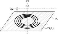
일실시예에서, 제1 베벨기어(161)는 카트리지 하우징(110) 외부로부터 회전력을 제공받아 카트리지 하우징(110) 내부에서 회전될 수 있다. 예컨대, 도 7에 예시된 바와 같이 핸드피스(200)에 구비되는 제2 모터(135)의 회전력이 구동축(136)을 통해 제1 베벨기어(161)로 전달될 수 있다. 일실시예에서 제2 베벨기어(162)는 제1 베벨기어(161)에 맞물리고 제1 베벨기어(161)의 회전운동에 맞춰 회전될 수 있다. 여기서, 제1 베벨기어(161)의 회전축을 제1 회전축(X1)이라 칭하고, 제2 베벨기어(162)의 회전축을 제2 회전축(X2)이라 칭할 수 있다. 제1 회전축(X1)은 초음파 치료부가 나선형으로 이동되는 구동평면(PL)에 수직을 이룰 수 있다. 즉, 제1 회전축은 구동평면(PL)의 법선과 평행할 수 있다. 그리고, 제2 회전축(X2)은 구동평면(PL)과 평행할 수 있으며, 구동핀(163) 또한 제2 회전축(X2)을 축으로 하여 회전될 수 있다. 도 8에는 제1 회전축(X1), 제2 회전축(X2) 및 구동평면(PL)의 관계가 예시되며, 구동평면(PL)상에서 나선형을 이루는 초음파 치료부의 궤적(TRAJ)이 이해될 수 있을 것이다.In one embodiment, the
일실시예에서, 구동핀 가이드(164)는 구동핀(163)이 회동가능하게 고정되는 요소로써, 제1 회전축(X1)을 중심으로 회동가능하게 구비될 수 있다. 일 예로써, 제1 베벨기어(161)의 회전축을 중심으로 회전하는 회전 가이드(165)가 구비되고, 이 회전 가이드(165) 상에 구동핀 가이드(164)의 일측이 결합되어 회전 가이드(165)의 회전에 따라 구동핀 가이드(164)가 제1 회전축(X1)을 중심으로 회동될 수 있다. 이때 제2 베벨기어(162)의 회전력에 의하여 구동핀(163)이 제2 회전축(X2)을 축으로 회전될 수 있으며, 그 결과 트랜스듀서(151)가 제1 회전축(X1)으로부터 멀어지는 방향으로 이동될 수 있다. 이때, 회전방향이 전환되면 트랜스듀서(151)가 제1 회전축(X1)에 가까워지는 방향으로 이동될 수도 있다. 이러한 작동원리는 도 9를 통해서 쉽게 이해될 수 있을 것이다. 다만, 도 9에서 제1 회전축(X1)을 축으로 하는 회전의 회전량 대비 트랜스듀서(151)의 직선이동 거리는 필요에 따라 적절히 조절될 수 있다.In one embodiment, the driving
일실시예에서, 제1 베벨기어(161)의 회전력이 제2 베벨기어(162)에 전달되면서 제2 베벨기어(162)가 회전되고, 더불어 구동핀 가이드(164)가 제1 회전축(X1)을 중심으로 회동될 수 있다.In one embodiment, as the rotational force of the
일실시예에서, 구동핀(163)에 제2 가이드(172)가 구비되고, 제2 가이드(172)에 초음파 치료부가 결합될 수 있다. 여기서, 전술한 실시예와 유사하게, 본 실시예에서도 초음파 치료부가 제1 가이드(152)와 트랜스듀서(151)를 포함할 수 있다.In one embodiment, a
일실시예에서, 도시되지는 않았지만, 트랜스듀서(151)와 제2 가이드(172) 사이의 거리가 증가되거나 감소될 수 있다. 도시되지는 않았지만 회전 가이드(165)가 제1 회전축을 따라 상승하거나 하강할 수도 있다. 이 경우, 트랜스듀서(151)와 제2 가이드(172) 사이의 거리가 증가되거나 감소되지 않더라도 열적 초점(10)의 깊이가 조절될 수 있다. 여기서, 회전 가이드(165) 자체가 제1 회전축(XL1)을 따라 상승하거나 하강할 수도 있으며, 회전 가이드(165)를 고정하는 제3 가이드부(도 6의 180) 전체가 제1 회전축(XL1)에 평행한 방향으로 상승하거나 하강할 수도 있다.In one embodiment, although not shown, the distance between the
일실시예에서, 회전 가이드(165)의 회전속도는 제1 베벨기어(161)의 회전속도와 다를 수 있다. 이를 위하여 구동축(136)은 회전 가이드(165) 내부를 관통하여 제1 베벨기어(161)에 결합되고, 구동축(136)과 회전 가이드(165) 사이를 간접적으로 연결하여 구동축(136)의 회전운동을 부분적으로 회전 가이드(165)에 전달하는 요소가 더 구비될 수 있다.In one embodiment, the rotation speed of the
본 발명의 일실시예에 따른 초음파 시술 장치(2000)는 제2 센서부(190)를 더 포함할 수 있다. 이 제2 센서부(190)는 트랜스듀서(151)의 위치 및/또는 회전 정도를 감지하는 기능을 수행할 수 있다. 일실시예에서, 제2 센서부(190)를 통해서 제1 회전축(X1)을 중심으로 하는 회전의 정도가 감지될 수 있다. 일 예로, 제2 모터(135)의 회전력을 전달하는 구동축(136)에 통공(137)을 구비하고, 이 구동축(136)을 사이에 두고 양측에 발광부(191)와 수광부(192)를 배치함으로써 구동축(136)의 회전을 감지하는 방식으로 작동될 수 있다.The
일실시예에서, 제2 센서부(190)를 통해서 트랜스듀서(151)의 위치가 감지될 수 있다. 일 예로, 트랜스듀서(151)와 함께 이동되는 구성요소들(제1 가이드(152), 제2 가이드(172)) 중에서 적어도 하나에 자력부(196)를 구비하고, 핸드피스(200)에 홀센서(195)가 구비되도록 할 수 있다. 이에 따라, 트랜스듀서(151)의 위치를 보다 정밀하게 검출하여 제어에 활용할 수 있다.In one embodiment, the position of the
한편, 전술한 발광부(191), 수광부(192), 홀센서(195) 등은 핸드피스에 구비되고, 전술한 자력부(196)는 카트리지 하우징(110) 내측에 구비될 수 있다. 카트리지 하우징(110) 내부에는 초음파의 전달 및 트랜스듀서의 냉각을 위한 액체가 충진되어야 하는데, 자력부(196)는 통상의 자석으로 구현될 수 있으므로 액체와 접촉해도 무방한 반면에, 발광부(191), 수광부(192) 및 홀센서(195)는 전원 및 신호 전달을 위한 요소들이 구비되어야 하므로 액체와 접촉되어야 한다면 별도의 방수 조치가 필요하다. 그러나, 본 발명의 일실시예에 따르면 발광부(191), 수광부(192), 홀센서(195) 등은 핸드피스(200)에 구비됨으로써 액체로부터 격리되므로 별도의 방수조치가 불필요하다는 장점을 가질 수 있다. 일실시예에서, 핸드피스(200) 내측에 회로기판(CB)이 구비되고, 이 회로기판(CB) 상에 발광부(191), 수광부(192), 홀센서(195) 등이 배치되도록 함으로써 제조효율 및 공간 활용성이 향상될 수 있다.Meanwhile, the above-described
도 10 등을 참조하면, 일실시예에서 트랜스듀서(151)와 제1 회전축(X1) 사이의 거리가 최소화될 수 있도록 제1 가이드(152-1)가 절곡된 형상으로 이루어질 수 있다. 즉, 제1 가이드(152-1)가 도 9에 예시된 바와 같이 절곡됨으로써 트랜스듀서(151)가 제2 가이드(172)와 제1 회전축(X1) 사이에 트랜스듀서(151)가 위치될 수 있다는 것이다. 이에 따라, 제1, 2 베벨기어의 결합관계에도 불구하고 트랜스듀서(151)가 나선형 회전의 중심부근에도 도달될 수 있으므로 시술의 효율성이 향상될 수 있다.Referring to FIG. 10 and the like, in one embodiment, the first guide 152-1 may be formed in a bent shape so that the distance between the
일반적으로, 연속적으로 형성되는 열적 초점들 사이의 간격이 과도하게 가까울 경우 피부조직이 손상될 위험성이 커서 소정의 안전거리를 유지하면서 열적 초점들을 형성하게 하고 있었다. 즉, 제1 샷 직후에 제2 샷을 하는 경우, 제1 샷에 의한 열적 초점과 제2 샷에 의한 열적 초점들 사이의 이격 거리를 감소시키는데 한계가 있었다는 것이다. 그러나, 본 실시예에 따르면 초음파 치료부가 360도 회전되는 과정에 소정의 시간이 소요되는 바, 나선의 간격이 더 좁아질 수 있으며, 그 결과 피부 조직의 손상 위험성을 낮추면서도 캐비테이션 효과의 중첩작용에 의하여 치료 효능이 향상될 수 있다.
In general, when the distance between thermal focal points formed continuously is too close, the risk of skin tissue damage is high, and thermal focal points are formed while maintaining a predetermined safety distance. That is, when the second shot was taken immediately after the first shot, there was a limit in reducing the separation distance between the thermal focus by the first shot and the thermal focus by the second shot. However, according to the present embodiment, since the ultrasound treatment part takes a predetermined time in the process of rotating 360 degrees, the interval between the spirals may be narrower, and as a result, the overlapping effect of the cavitation effect is reduced while reducing the risk of skin tissue damage. By this, the treatment efficacy can be improved.
1000 : 초음파 시술 장치
10 : 열적 초점
100 : 카트리지
110 : 카트리지 하우징
111 : 제1 프레임
115 : 윈도우
118 : 제1 센서부
120 : 초음파 치료부
121 : 트랜스듀서
122 : 제1 가이드부
123 : 제1 모터
124 : 피니언
130 : 제1 구동부
131 : 구동캠
132 : 제1 기어
133 : 제2 기어
134 : 가이드레일
140 : 제2 구동부
141 : 래크
142 : 제2 가이드부
151 : 트랜스듀서
152 : 제1 가이드
161 : 제1 베벨기어
162 : 제2 베벨기어
163 : 구동핀
164 : 구동핀 가이드
165 : 회전 가이드
172 : 제2 가이드
180 : 제3 가이드
190 : 제2 센서부
200 : 핸드피스
210u : 상부 하우징
210b : 하부 하우징
220 : 제1 스위치
MCU : 제어부
PM : 전원모듈
IG : 이미징 모듈
DP : 디스플레이 모듈
PL : 구동평면1000: ultrasound treatment device
10: thermal focus
100: cartridge
110: cartridge housing
111: first frame
115: Windows
118: first sensor unit
120: ultrasound treatment unit
121: transducer
122: first guide unit
123: first motor
124: pinion
130: first driving unit
131: Driving cam
132: first gear
133: second gear
134: Guide rail
140: second driving unit
141: Rack
142: second guide section
151: transducer
152: first guide
161: 1st bevel gear
162: second bevel gear
163: driving pin
164: Driving pin guide
165: rotation guide
172: second guide
180: third guide
190: second sensor unit
200: handpiece
210u: upper housing
210b: lower housing
220: first switch
MCU: Control
PM: Power module
IG: imaging module
DP: display module
PL: Driving plane
Claims (7)
Translated fromKorean상기 카트리지 내부에 구비되어 초음파를 발생시키는 초음파 치료부; 및
상기 윈도우로부터 이격되며 상기 윈도우와 평행인 구동평면 상에서 상기 초음파 치료부를 나선형으로 이동시키는 구동부;
를 포함하되,
상기 구동부는,
상기 구동평면의 법선과 평행한 제1 회전축을 갖는 제1 베벨기어;
상기 구동평면과 평행한 제2 회전축을 갖는 제2 베벨기어;
상기 제2 베벨기어에 구비되어 상기 제2 회전축을 축으로 회전되는 구동핀;
상기 제1 회전축을 중심으로 회동되며, 상기 구동핀에 결합되어 상기 제1 회전축을 중심으로 하는 상기 구동핀의 회동을 안내하는 구동핀 가이드;
상기 제2 회전축을 축으로 하는 상기 구동핀의 회전에 의하여 상기 구동핀 상에서 전진 또는 후진하며, 상기 초음파 치료부가 일측에 결합되는 가이드; 및
상기 제1 회전축을 중심축으로 회전되는 회전 가이드;를 포함하고,
상기 구동핀 가이드의 일측이 상기 회전 가이드에 결합되어 상기 회전 가이드의 회전에 따라 상기 구동핀 가이드가 회동되는 초음파 시술 장치.
A cartridge equipped with a window for transmitting ultrasound;
An ultrasonic treatment unit provided inside the cartridge to generate ultrasonic waves; And
A driving unit spaced apart from the window and helically moving the ultrasound treatment unit on a driving plane parallel to the window;
Including,
The driving unit,
A first bevel gear having a first axis of rotation parallel to the normal of the driving plane;
A second bevel gear having a second rotational axis parallel to the driving plane;
A driving pin provided on the second bevel gear and rotating about the second rotating shaft;
A drive pin guide which is rotated around the first rotation axis and is coupled to the drive pin to guide rotation of the drive pin around the first rotation axis;
A guide which is advanced or reversed on the driving pin by rotation of the driving pin having the second rotation axis as an axis, and the ultrasonic treatment unit is coupled to one side; And
It includes; a rotation guide that is rotated about the first rotation axis as a central axis,
An ultrasonic surgical device in which one side of the driving pin guide is coupled to the rotating guide and the driving pin guide is rotated according to the rotation of the rotating guide.
상기 제1 베벨기어가 회전되면, 상기 제2 베벨기어가 상기 제2 회전축을 축으로 회전되면서 상기 구동핀 가이드가 상기 제1 회전축을 중심으로 회동되는 것을 특징으로 하는 초음파 시술 장치.
The method of claim 1,
When the first bevel gear is rotated, the second bevel gear is rotated about the second rotation shaft, the driving pin guide is rotated around the first rotation axis, ultrasound treatment apparatus.
홀센서가 구비된 회로기판, 회전력을 발생시키는 모터 및 상기 모터의 회전력을 전달하는 구동축이 구비된 핸드피스를 더 포함하며,
자력을 발생시키는 자력부가 상기 초음파 치료부에 구비되고,
상기 홀센서는 상기 자력을 감지하여 상기 초음파 치료부의 위치를 도출하는 것을 특징으로 하는 초음파 시술 장치.
The method of claim 1,
Further comprising a circuit board with a Hall sensor, a motor for generating rotational force and a handpiece with a drive shaft for transmitting the rotational force of the motor,
A magnetic force generating magnetic force is provided in the ultrasonic treatment part,
The hall sensor is an ultrasonic surgical device characterized in that to derive the position of the ultrasonic treatment unit by sensing the magnetic force.
상기 구동평면과 상기 윈도우 사이의 이격거리를 증가시키거나 감소시키는 부가 구동부;를 더 포함하고,
상기 구동평면은 제1 구동평면 및 제2 구동평면을 포함하되, 상기 제1 구동평면은 제1 거리만큼 상기 윈도우로부터 이격되고, 상기 제2 구동평면은 상기 제1 거리보다 작은 제2 거리만큼 상기 윈도우로부터 이격되는 초음파 시술 장치.
The method of any one of claims 1, 5, and 6,
Further comprising; an additional driving unit for increasing or decreasing the separation distance between the driving plane and the window;
The driving plane includes a first driving plane and a second driving plane, wherein the first driving plane is spaced from the window by a first distance, and the second driving plane is by a second distance smaller than the first distance. Ultrasound treatment device spaced from the window.
Applications Claiming Priority (2)
| Application Number | Priority Date | Filing Date | Title |
|---|---|---|---|
| KR1020170013458 | 2017-01-31 | ||
| KR20170013458 | 2017-01-31 |
Publications (2)
| Publication Number | Publication Date |
|---|---|
| KR20180089309A KR20180089309A (en) | 2018-08-08 |
| KR102094444B1true KR102094444B1 (en) | 2020-03-27 |
Family
ID=63230066
Family Applications (1)
| Application Number | Title | Priority Date | Filing Date |
|---|---|---|---|
| KR1020180010855AActiveKR102094444B1 (en) | 2017-01-31 | 2018-01-29 | Ultrasound operating apparatus |
Country Status (1)
| Country | Link |
|---|---|
| KR (1) | KR102094444B1 (en) |
Cited By (4)
| Publication number | Priority date | Publication date | Assignee | Title |
|---|---|---|---|---|
| KR20220083540A (en)* | 2020-12-11 | 2022-06-20 | (주)비올 | Ultrasound apparatus with reciprocating transfer way of transducer |
| KR20240163318A (en) | 2023-05-10 | 2024-11-19 | 박종수 | Facial beauty treatment equipment |
| US12415095B2 (en) | 2020-12-11 | 2025-09-16 | Viol Co., Ltd. | Ultrasound apparatus with two-row transfer way of transducer |
| US12440705B2 (en) | 2020-12-11 | 2025-10-14 | Viol Co., Ltd. | Ultrasound apparatus with reciprocating transfer way of transducer |
Families Citing this family (8)
| Publication number | Priority date | Publication date | Assignee | Title |
|---|---|---|---|---|
| KR102111103B1 (en)* | 2018-09-13 | 2020-05-14 | 주식회사 이루다 | High intensity focused ultrasound device and control method of piezo-electric driving device used to the same |
| US11247075B2 (en)* | 2018-12-21 | 2022-02-15 | Industrial Technology Research Institute | Ultrasonic probe device |
| KR102165046B1 (en)* | 2020-03-04 | 2020-10-13 | 이가연 | Cartridge with dirve unit inside coupled with high intensity focused ultrasonic device and high intensity focused ultrasonic device with cartridge |
| KR102412736B1 (en)* | 2020-04-21 | 2022-06-23 | 박종철 | Cartridge for focused ultrasound device and focused ultrasound device comprising same |
| KR102522627B1 (en)* | 2020-09-17 | 2023-04-17 | 주식회사 제이시스메디칼 | Ultrasonic medical instrument with adjusable focusing depth of ultrasonic wave generator |
| JP2025531568A (en)* | 2022-09-30 | 2025-09-19 | プリスキン インコーポレイテッド | Lifting beauty device using high-intensity focused ultrasound |
| KR20240045951A (en)* | 2022-09-30 | 2024-04-08 | 퓨리스킨 알앤디 주식회사 | Lifting beauty device using high-intensity focused ultrasound |
| KR102650092B1 (en)* | 2023-03-03 | 2024-03-21 | 장대규 | Lifting beauty device using high-intensity focused ultrasound |
Citations (2)
| Publication number | Priority date | Publication date | Assignee | Title |
|---|---|---|---|---|
| JP2006026262A (en)* | 2004-07-21 | 2006-02-02 | Aloka Co Ltd | Ultrasonic probe |
| KR101335476B1 (en)* | 2013-02-25 | 2013-12-11 | 주식회사 코러스트 | Line-focus type ultrasound transducer and high intensity focused ultrasound generating apparatus including the same |
Family Cites Families (5)
| Publication number | Priority date | Publication date | Assignee | Title |
|---|---|---|---|---|
| JP2008036199A (en) | 2006-08-08 | 2008-02-21 | Olympus Corp | Endoscope system |
| CN104027893B (en) | 2013-03-08 | 2021-08-31 | 奥赛拉公司 | Apparatus and method for multifocal ultrasound therapy |
| KR102066002B1 (en) | 2013-06-10 | 2020-02-11 | 삼성전자주식회사 | Polishing pad compound |
| WO2015160708A1 (en)* | 2014-04-18 | 2015-10-22 | Ulthera, Inc. | Band transducer ultrasound therapy |
| KR102447731B1 (en) | 2015-05-28 | 2022-09-27 | 주식회사 하이로닉 | High-intensity focused ultrasound device |
- 2018
- 2018-01-29KRKR1020180010855Apatent/KR102094444B1/enactiveActive
Patent Citations (2)
| Publication number | Priority date | Publication date | Assignee | Title |
|---|---|---|---|---|
| JP2006026262A (en)* | 2004-07-21 | 2006-02-02 | Aloka Co Ltd | Ultrasonic probe |
| KR101335476B1 (en)* | 2013-02-25 | 2013-12-11 | 주식회사 코러스트 | Line-focus type ultrasound transducer and high intensity focused ultrasound generating apparatus including the same |
Cited By (5)
| Publication number | Priority date | Publication date | Assignee | Title |
|---|---|---|---|---|
| KR20220083540A (en)* | 2020-12-11 | 2022-06-20 | (주)비올 | Ultrasound apparatus with reciprocating transfer way of transducer |
| KR102553256B1 (en) | 2020-12-11 | 2023-07-07 | (주)비올 | Ultrasound apparatus with reciprocating transfer way of transducer |
| US12415095B2 (en) | 2020-12-11 | 2025-09-16 | Viol Co., Ltd. | Ultrasound apparatus with two-row transfer way of transducer |
| US12440705B2 (en) | 2020-12-11 | 2025-10-14 | Viol Co., Ltd. | Ultrasound apparatus with reciprocating transfer way of transducer |
| KR20240163318A (en) | 2023-05-10 | 2024-11-19 | 박종수 | Facial beauty treatment equipment |
Also Published As
| Publication number | Publication date |
|---|---|
| KR20180089309A (en) | 2018-08-08 |
Similar Documents
| Publication | Publication Date | Title |
|---|---|---|
| KR102094444B1 (en) | Ultrasound operating apparatus | |
| KR101756618B1 (en) | Ultrasound operating apparatus | |
| KR101893584B1 (en) | Ultrasound operating apparatus | |
| JP6931244B2 (en) | Ultrasonic treatment device | |
| CN207950348U (en) | Ultrasonic wave generator | |
| JP7495761B2 (en) | An ultrasonic generator that allows you to adjust the ultrasonic focusing depth | |
| KR101713318B1 (en) | High intensity focused ultrasound operating apparatus | |
| KR102168246B1 (en) | High intensity focused ultrasound operating apparatus | |
| KR102118017B1 (en) | Piezo-electric driving device and high intensity focused ultrasound(hifu) handpiece device using the same | |
| KR102149062B1 (en) | Intensity focused ultrasound operating apparatus | |
| KR102412736B1 (en) | Cartridge for focused ultrasound device and focused ultrasound device comprising same | |
| JP2012519549A (en) | Ultrasound treatment of adipose tissue at multiple depths | |
| KR102118019B1 (en) | High intensity focused ultrasound(hifu) device and stand alone type cartridge detachably combined with hifu hanpiece used to the same | |
| KR102581952B1 (en) | Focused ultrasound operating apparatus | |
| KR101791550B1 (en) | Head of ultrasonic therapy system for treatment | |
| KR20230129361A (en) | High intensity focused ultrasound operating apparatus and driving method thereof | |
| KR102105146B1 (en) | Operating apparatus for skin treatment | |
| KR20140138030A (en) | Device for generating high intensity focused ultrasound | |
| KR20160062984A (en) | Ultrasound apparatus | |
| KR102117636B1 (en) | Ultrasound treatment cartridge and treatment apparatus having the same | |
| KR20150060644A (en) | High Intensity Focused Ultrasonic Medical Instrument | |
| KR101750015B1 (en) | Ultrasound apparatus | |
| KR102840413B1 (en) | Cartridge for focused ultrasound device and focused ultrasound device comprising same | |
| US12440705B2 (en) | Ultrasound apparatus with reciprocating transfer way of transducer | |
| EP4260903A1 (en) | Ultrasound apparatus with reciprocating movement-type transducer |
Legal Events
| Date | Code | Title | Description |
|---|---|---|---|
| A201 | Request for examination | ||
| PA0109 | Patent application | Patent event code:PA01091R01D Comment text:Patent Application Patent event date:20180129 | |
| PA0201 | Request for examination | Patent event code:PA02012R01D Patent event date:20180129 Comment text:Request for Examination of Application | |
| PG1501 | Laying open of application | ||
| E902 | Notification of reason for refusal | ||
| PE0902 | Notice of grounds for rejection | Comment text:Notification of reason for refusal Patent event date:20190820 Patent event code:PE09021S01D | |
| E701 | Decision to grant or registration of patent right | ||
| PE0701 | Decision of registration | Patent event code:PE07011S01D Comment text:Decision to Grant Registration Patent event date:20200226 | |
| GRNT | Written decision to grant | ||
| PR0701 | Registration of establishment | Comment text:Registration of Establishment Patent event date:20200323 Patent event code:PR07011E01D | |
| PR1002 | Payment of registration fee | Payment date:20200323 End annual number:3 Start annual number:1 | |
| PG1601 | Publication of registration | ||
| PR1001 | Payment of annual fee | Payment date:20230323 Start annual number:4 End annual number:4 | |
| PR1001 | Payment of annual fee | Payment date:20250211 Start annual number:6 End annual number:6 |