KR102093841B1 - Laser processing systems using through-the-lens alignment of a laser beam with a target feature - Google Patents
Laser processing systems using through-the-lens alignment of a laser beam with a target featureDownload PDFInfo
- Publication number
- KR102093841B1 KR102093841B1KR1020177011821AKR20177011821AKR102093841B1KR 102093841 B1KR102093841 B1KR 102093841B1KR 1020177011821 AKR1020177011821 AKR 1020177011821AKR 20177011821 AKR20177011821 AKR 20177011821AKR 102093841 B1KR102093841 B1KR 102093841B1
- Authority
- KR
- South Korea
- Prior art keywords
- laser beam
- processing
- workpiece
- aod
- subsystem
- Prior art date
- Legal status (The legal status is an assumption and is not a legal conclusion. Google has not performed a legal analysis and makes no representation as to the accuracy of the status listed.)
- Active
Links
Images


Classifications
- B—PERFORMING OPERATIONS; TRANSPORTING
- B23—MACHINE TOOLS; METAL-WORKING NOT OTHERWISE PROVIDED FOR
- B23K—SOLDERING OR UNSOLDERING; WELDING; CLADDING OR PLATING BY SOLDERING OR WELDING; CUTTING BY APPLYING HEAT LOCALLY, e.g. FLAME CUTTING; WORKING BY LASER BEAM
- B23K26/00—Working by laser beam, e.g. welding, cutting or boring
- B23K26/02—Positioning or observing the workpiece, e.g. with respect to the point of impact; Aligning, aiming or focusing the laser beam
- B23K26/03—Observing, e.g. monitoring, the workpiece
- B23K26/032—Observing, e.g. monitoring, the workpiece using optical means
- B—PERFORMING OPERATIONS; TRANSPORTING
- B23—MACHINE TOOLS; METAL-WORKING NOT OTHERWISE PROVIDED FOR
- B23K—SOLDERING OR UNSOLDERING; WELDING; CLADDING OR PLATING BY SOLDERING OR WELDING; CUTTING BY APPLYING HEAT LOCALLY, e.g. FLAME CUTTING; WORKING BY LASER BEAM
- B23K26/00—Working by laser beam, e.g. welding, cutting or boring
- B23K26/02—Positioning or observing the workpiece, e.g. with respect to the point of impact; Aligning, aiming or focusing the laser beam
- B23K26/04—Automatically aligning, aiming or focusing the laser beam, e.g. using the back-scattered light
- B23K26/046—Automatically focusing the laser beam
- B—PERFORMING OPERATIONS; TRANSPORTING
- B23—MACHINE TOOLS; METAL-WORKING NOT OTHERWISE PROVIDED FOR
- B23K—SOLDERING OR UNSOLDERING; WELDING; CLADDING OR PLATING BY SOLDERING OR WELDING; CUTTING BY APPLYING HEAT LOCALLY, e.g. FLAME CUTTING; WORKING BY LASER BEAM
- B23K26/00—Working by laser beam, e.g. welding, cutting or boring
- B23K26/02—Positioning or observing the workpiece, e.g. with respect to the point of impact; Aligning, aiming or focusing the laser beam
- B23K26/06—Shaping the laser beam, e.g. by masks or multi-focusing
- B23K26/064—Shaping the laser beam, e.g. by masks or multi-focusing by means of optical elements, e.g. lenses, mirrors or prisms
- B23K26/0648—Shaping the laser beam, e.g. by masks or multi-focusing by means of optical elements, e.g. lenses, mirrors or prisms comprising lenses
- B—PERFORMING OPERATIONS; TRANSPORTING
- B23—MACHINE TOOLS; METAL-WORKING NOT OTHERWISE PROVIDED FOR
- B23K—SOLDERING OR UNSOLDERING; WELDING; CLADDING OR PLATING BY SOLDERING OR WELDING; CUTTING BY APPLYING HEAT LOCALLY, e.g. FLAME CUTTING; WORKING BY LASER BEAM
- B23K26/00—Working by laser beam, e.g. welding, cutting or boring
- B23K26/02—Positioning or observing the workpiece, e.g. with respect to the point of impact; Aligning, aiming or focusing the laser beam
- B23K26/06—Shaping the laser beam, e.g. by masks or multi-focusing
- B23K26/0665—Shaping the laser beam, e.g. by masks or multi-focusing by beam condensation on the workpiece, e.g. for focusing
- B—PERFORMING OPERATIONS; TRANSPORTING
- B23—MACHINE TOOLS; METAL-WORKING NOT OTHERWISE PROVIDED FOR
- B23K—SOLDERING OR UNSOLDERING; WELDING; CLADDING OR PLATING BY SOLDERING OR WELDING; CUTTING BY APPLYING HEAT LOCALLY, e.g. FLAME CUTTING; WORKING BY LASER BEAM
- B23K26/00—Working by laser beam, e.g. welding, cutting or boring
- B23K26/08—Devices involving relative movement between laser beam and workpiece
- B23K26/082—Scanning systems, i.e. devices involving movement of the laser beam relative to the laser head
- B—PERFORMING OPERATIONS; TRANSPORTING
- B23—MACHINE TOOLS; METAL-WORKING NOT OTHERWISE PROVIDED FOR
- B23K—SOLDERING OR UNSOLDERING; WELDING; CLADDING OR PLATING BY SOLDERING OR WELDING; CUTTING BY APPLYING HEAT LOCALLY, e.g. FLAME CUTTING; WORKING BY LASER BEAM
- B23K26/00—Working by laser beam, e.g. welding, cutting or boring
- B23K26/36—Removing material
- B23K26/40—Removing material taking account of the properties of the material involved
- B—PERFORMING OPERATIONS; TRANSPORTING
- B23—MACHINE TOOLS; METAL-WORKING NOT OTHERWISE PROVIDED FOR
- B23K—SOLDERING OR UNSOLDERING; WELDING; CLADDING OR PLATING BY SOLDERING OR WELDING; CUTTING BY APPLYING HEAT LOCALLY, e.g. FLAME CUTTING; WORKING BY LASER BEAM
- B23K2101/00—Articles made by soldering, welding or cutting
- B23K2101/36—Electric or electronic devices
- B23K2101/40—Semiconductor devices
- B—PERFORMING OPERATIONS; TRANSPORTING
- B23—MACHINE TOOLS; METAL-WORKING NOT OTHERWISE PROVIDED FOR
- B23K—SOLDERING OR UNSOLDERING; WELDING; CLADDING OR PLATING BY SOLDERING OR WELDING; CUTTING BY APPLYING HEAT LOCALLY, e.g. FLAME CUTTING; WORKING BY LASER BEAM
- B23K2103/00—Materials to be soldered, welded or cut
- B23K2103/50—Inorganic material, e.g. metals, not provided for in B23K2103/02 – B23K2103/26
- B23K2103/56—Inorganic material, e.g. metals, not provided for in B23K2103/02 – B23K2103/26 semiconducting
Landscapes
- Physics & Mathematics (AREA)
- Optics & Photonics (AREA)
- Engineering & Computer Science (AREA)
- Plasma & Fusion (AREA)
- Mechanical Engineering (AREA)
- Laser Beam Processing (AREA)
- Optical Modulation, Optical Deflection, Nonlinear Optics, Optical Demodulation, Optical Logic Elements (AREA)
- Mechanical Light Control Or Optical Switches (AREA)
- Mechanical Optical Scanning Systems (AREA)
- Micromachines (AREA)
Abstract
Translated fromKoreanDescription
Translated fromKorean본 내용은 유전체 또는 다른 재료들의 레이저 처리에 관한 것이다.This disclosure relates to laser processing of dielectrics or other materials.
유전체 및 전도성 재료들의 레이저 처리는 전자 구성요소들의 미세 특징부들을 융제하기 위해 일반적으로 사용된다. 예로서, 칩 패키징 기판들은 반도체 다이로부터 볼 그리드 어레이 또는 유사 패키지로 신호들을 라우팅하기 위해 레이저 처리될 수 있다. 레이저 처리된 특징부들은 신호 트레이스들, 접지 트레이스들 및 마이크로비아들(패키지 층들 사이의 신호 트레이스들의 연결을 위한)을 포함할 수 있다. 최근 디자인 경향은 칩 패키지 내의 층들의 수를 감소시키면서 신호 임피던스를 엄격하게 제어하기 위해 단일 층 상에 신호 및 접지 트레이스들을 통합시키고 있다. 이런 접근법은 작은 특징부 치수들과 간격(예를 들어, 약 10 미크론(㎛) 내지 약 25㎛) 및 패키지 당 긴 트레이스 길이(예를 들어, 약 5 미터(m) 내지 약 10 m)를 필요로 할 수 있다. 경제적으로 칩 패키지들을 구성하기 위해, 이런 특징부들이 융제되는 속도는 매우 높다(예를 들어, 약 1 미터/초(m/s)로부터 약 10 m/s). 특정 패키지들은 고객 처리량 목적들을 충족시키기 위해 예로서, 약 0.5 초(s) 내지 약 5s로 처리될 수 있다.Laser processing of dielectric and conductive materials is commonly used to fuse fine features of electronic components. As an example, chip packaging substrates can be lasered to route signals from a semiconductor die to a ball grid array or similar package. The lasered features can include signal traces, ground traces and microvias (for connection of signal traces between package layers). A recent design trend is integrating signal and ground traces on a single layer to tightly control signal impedance while reducing the number of layers in the chip package. This approach requires small feature dimensions and spacing (eg, about 10 microns (μm) to about 25 μm) and long trace length per package (eg, about 5 meters (m) to about 10 m). Can be done with To economically construct chip packages, the speed at which these features are fused is very high (eg, about 1 m / s (m / s) to about 10 m / s). Certain packages can be processed from about 0.5 seconds (s) to about 5s, for example, to meet customer throughput objectives.
칩 패키징의 다른 유용한 특성은 제어된 깊이 변동으로 교차 트레이스들을 제공하는 것일 수 있다. 예로서, 접지 트레이스들은 패턴을 통한 다수의 지점들에서 분기될 수 있다. 각 분기 교차부에서, 트레이스들은 약 +/- 10% 미만의 원하는 깊이 변동으로 융제될 수 있다. 일반적으로, 두 개의 트렌치들이 일 지점에서 융제되는 경우, 융제 비임의 이중적 노출은 약 100%의 깊이 변동을 생성한다.Another useful property of chip packaging may be to provide cross traces with controlled depth variations. As an example, ground traces may branch at multiple points through the pattern. At each branch intersection, traces can be fluxed with a desired depth variation of less than about +/- 10%. Generally, when two trenches are fused at one point, the double exposure of the flux beam creates a depth fluctuation of about 100%.
칩 패키징의 다른 유용한 특성은 층간 연결 비아들을 위한 패드들을 제공하거나 임피던스를 제어하기 위해 패키지의 다양한 부분들에서 가변적 트레이스 폭들을 제공하는 것일 수 있다. 트레이스 폭 제어는 주 트레이스의 고속 처리를 위해 감소된 또는 최소의 중단으로 제공되어야 한다.Another useful feature of chip packaging may be to provide pads for interlayer connecting vias or to provide variable trace widths in various parts of the package to control impedance. Trace width control should be provided with reduced or minimal interruptions for high-speed processing of the main trace.
또한, 이는 특징부의 특성들을 변화시키기 위해 감소된 또는 최소의 시간으로 임의적 크기 및 형상의 특징부들을 고속으로 처리하는데 유용할 수 있다. 예로서, 특징부들은 다양한 직경들 및/또는 측벽 테이퍼를 갖는 마이크로비아들, 정사각형 또는 직사각형 패드들, 정렬 기점들 및/또는 영숫자 표기를 포함할 수 있다. 통상적으로, 마이크로비아들 같은 특징부들을 처리하기 위해, 광학 시스템들은 순수 가우스 비임들 또는 가변 직경의 성형된 강도 프로파일들(예를 들어, 평면-상단 비임들)을 제공하도록 설계되어야 한다. 이들 광학 시스템들은 레이저 처리 스팟 특성들이 변할 때 충분한 시간 지연들(예를 들어, 약 10 밀리초(ms) 내지 약 10 s)을 가질 수 있다.In addition, it can be useful to process features of arbitrary size and shape at high speed with reduced or minimal time to change features of the feature. By way of example, the features can include microvias with various diameters and / or sidewall tapers, square or rectangular pads, alignment origins and / or alphanumeric notation. Typically, to process features such as microvias, optical systems must be designed to provide pure Gaussian beams or variable diameter shaped strength profiles (eg, planar-top beams). These optical systems can have sufficient time delays (eg, about 10 milliseconds (ms) to about 10 s) when the laser processing spot characteristics change.
다른 문제점들은 상술한 처리 파라미터들을 충족시키기 위한 기계를 구성하는 것과 연계되어 있다. 예로서, 트레이스들은 라우팅 요건들에 기인하여 패키지를 통한 방향을 변화시킬 수 있다. 고속으로 트레이스들을 처리할 때, 궤적 각도의 변화는 매우 짧은 시간 규모들로 높은 비임 위치 정확도를 필요로 할 수 있다. 레이저 처리는 예로서, 높은 처리량을 위해 사용되는 높은 속도들(예를 들어, 약 1 m/s 내지 약 10 m/s)로 구동될 때 비임 위치설정기의 동적 한계들을 쉽게 초과할 수 있다.Other problems are associated with constructing a machine to meet the above-described processing parameters. By way of example, traces can change direction through the package due to routing requirements. When processing traces at high speed, changes in trajectory angle may require high beam position accuracy on very short time scales. The laser treatment can easily exceed the dynamic limits of the beam positioner when driven at high speeds (eg, about 1 m / s to about 10 m / s) used for high throughput, for example.
이런 가속들 및/또는 속도들은 이 유형의 처리에 사용되는 시간 규모들(예를 들어, 약 1 마이크로초(μs) 내지 약 100 μs 정도)에 응답할 수 없는 정적(또는 저속으로 변하는) 비임 상태조정 광학장치와 함께 거울 갈바노미터 비임 편향기들(본 명세서에서 "갤보들(galvos)" 또는 "갤보 거울들"이라 지칭되는)과 조합된 선형 스테이지들 같은 비임 위치설정 기술들에 의존할 수 있는 통상적 레이저 처리 기계들에서는 달성하기가 어려울 수 있다.These accelerations and / or velocities are static (or changing at a slow) beam state that cannot respond to the time scales used in this type of processing (eg, on the order of about 1 microsecond (μs) to about 100 μs). Beam positioning techniques, such as linear stages combined with mirror galvanometer beam deflectors (referred to herein as “galvos” or “galvo mirrors”) with adjustment optics, may be relied upon. It can be difficult to achieve in conventional laser processing machines.
또한, 실제 융제 처리는 고려 대상 인자일 수 있다. 고 피크 파워를 갖는 레이저 펄스들은 용융, 크랙킹 및 기판 손상 같은 열적 부차적 영향들을 최소화하면서 유전체 재료를 융제하기 위해 사용될 수 있다. 예로서, 약 5 메가헤르쯔(MHz) 내지 약 100 MHz의 반복율들로 약 20 피코초(ps)와 약 50 ps 사이의 범위의 펄스 폭들을 갖는 초급속 레이저들이 펄스 간격 효과들을 피하기 위해 충분한 펄스 중첩을 제공하면서 높은 피크 파워로 재료들을 처리할 수 있다. 이제, 파이버 레이저들은 일반적으로 약 500 킬로헤르쯔(kHz)보다 큰 반복율로 나노초 영역에서 펄스 폭들을 제공한다. 일반적으로, 주어진 처리 조건(융제 깊이 및 폭)에 대하여, 처리된 재료에 인가되는 "투여량"(파워/속도) 일정하여야 한다. 그러나, 낮은 속도들에서, 인가된 파워는 피크 펄스 파워가 열적 영향들(예를 들어, 용융 및 차링(charring))을 유도하지 않고 재료를 융제하기에 불충분하게 너무 낮아질 수 있다.Also, the actual flux treatment may be a factor to be considered. Laser pulses with high peak power can be used to flux the dielectric material while minimizing thermal side effects such as melting, cracking and substrate damage. As an example, ultra-fast lasers with pulse widths ranging from about 20 picoseconds (ps) to about 50 ps with repetition rates of about 5 MHz (MHz) to about 100 MHz provide sufficient pulse overlap to avoid pulse spacing effects. While providing, the materials can be processed with high peak power. Now, fiber lasers typically provide pulse widths in the nanosecond region with a repetition rate greater than about 500 kilohertz (kHz). In general, for a given treatment condition (depth and width of melt), the "dose" (power / speed) applied to the treated material should be constant. However, at low speeds, the applied power may be too low for the peak pulse power to be insufficient to flux the material without inducing thermal effects (eg, melting and charring).
융제 효율을 감소시킬 수 있는 다른 처리 효과는 융제된 재료의 플룸(plume)과의 처리 비임의 상호작용일 수 있다. 플룸들은 그 편향에 기인하여 정확도 문제들을 유발하거나 집속된 비임을 교란시키기에 충분하게 비임을 왜곡시키거나 편향시킬 수 있다.Another treatment effect that can reduce the fluxing efficiency can be the interaction of the treatment beam with a plume of the fluxed material. Plumes may cause accuracy problems due to the deflection or distort or deflect the beam sufficient to disturb the focused beam.
비임 위치설정기 디자인들은 갤보들을 사용하여 처리 비임을 편향시킬 수 있다. 작업편에서 처리 비임의 강도 프로파일은 고정된 광학 비임 성형기에 의해 상태조정된 비임들을 위한 가우스(가우스 비임의 단순 집속을 위한) 또는 성형된 강도 프로파일(예를 들어, 평면-상단 프로파일)일 수 있다.Beam positioner designs can use galvos to deflect the processing beam. The intensity profile of the treated beam in the workpiece can be a Gaussian (for simple focusing of the Gaussian beam) or a shaped intensity profile (eg, a planar-top profile) for beams conditioned by a fixed optical beam forming machine. .
음향-광학 편향기들(acousto-optic deflectors)(AODs)이 고속 편향을 제공하기 위해 갤보들과 조합되는 시스템들이 예로서, 미국 특허 제5,837,962호 및 제7,133,187호에 개시되어 있다. 그러나, 이들 참조문헌들은 진보된 비임 위치설정기 디자인으로 원하는 성능을 획득하는 것을 개시하지 못하고 있다.Systems in which acoustic-optic deflectors (AODs) are combined with galvos to provide high-speed deflection are disclosed, for example, in US Pat. Nos. 5,837,962 and 7,133,187. However, these references do not disclose achieving the desired performance with an advanced beam locator design.
일 실시예에서, 작업편을 마이크로기계가공하기 위한 레이저 처리 시스템은 작업편의 표면에 특징부를 처리하기 위해 일련의 레이저 펄스들을 생성하기 위한 레이저 소스와, 작업편의 표면에 관하여 처리 궤적을 따른 레이저 비임 스팟 위치의 제1 상대적 이동을 부여하기 위한 갈바노미터-구동(갤보) 서브시스템과, 음향-광학 편향기(AOD) 서브시스템을 포함한다. AOD 서브시스템은 AOD들과 전자-광학 편향기들의 조합을 포함할 수 있다.In one embodiment, a laser processing system for micromachining a workpiece includes a laser source for generating a series of laser pulses to process features on the surface of the workpiece, and a laser beam spot along the treatment trajectory with respect to the surface of the workpiece And a galvanometer-driven (galvo) subsystem for imparting a first relative movement of position, and an acoustic-optical deflector (AOD) subsystem. The AOD subsystem can include a combination of AODs and electro-optical deflectors.
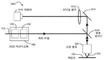
일 실시예에서, 작업편 특징부들에 처리 레이저 비임을 정렬시키기 위한 방법이 제공된다. 처리 레이저 비임은 작업편 특징부들을 처리하기 위한 사전결정된 파장을 포함한다. 이 방법은 스캔 렌즈를 통해 전파 경로를 따라 작업편으로 처리 레이저 비임을 전파하는 단계를 포함한다. 또한, 이 방법은 사전결정된 파장의 조작된 처리 레이저 비임으로 정렬 타겟을 포함하는 작업편의 선택된 영역을 스캔 렌즈를 통해 조명하도록 처리 레이저 비임을 조작하는 단계를 포함한다. 선택된 영역은 스캔 렌즈를 통해 제공된 처리 레이저 비임의 기준 레이저 비임 스팟 보다 크다. 이 방법은 작업편의 선택된 영역을 이미징하기 위해 카메라에 스캔 렌즈를 통해 조작된 처리 레이저 비임의 반사의 적어도 일부를 다시 안내하는 단계를 더 포함한다. 카메라에 의해 포착된 선택된 영역의 이미지에 기초하여, 이 방법은 또한 정렬 타겟에 대하여 기준 레이저 비임 스팟의 위치를 결정하는 단계를 포함한다.In one embodiment, a method is provided for aligning a processing laser beam to workpiece features. The processing laser beam includes a predetermined wavelength for processing workpiece features. The method includes propagating the processed laser beam through the scan lens along the propagation path to the workpiece. The method also includes manipulating the process laser beam to illuminate through a scan lens a selected area of the workpiece including the alignment target with a manipulated process laser beam of a predetermined wavelength. The selected area is larger than the reference laser beam spot of the treatment laser beam provided through the scan lens. The method further includes directing at least a portion of the reflection of the processed laser beam manipulated through the scan lens to the camera to image the selected area of the workpiece. Based on the image of the selected area captured by the camera, the method also includes determining the position of the reference laser beam spot relative to the alignment target.
도 1은 특정 실시예들에 따라 사용될 수 있는 AOD의 동작을 예시하는 블록도이다.
도 2는 특정 실시예들에 따라 사용될 수 있는 다양한 RF 주파수들에서 AOD 회절 효율 곡선들에 대한 RF 파워를 도식적으로 나타낸다.
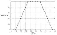
도 3은 일 실시예에 따른 원하는 감쇄를 선택하기 위해 사용되는 예시적 AOD 파워 선형화 곡선을 도식적으로 나타낸다.
도 4는 특정 실시예들에 따른 회절 효율과 편향 범위 사이의 절충을 선택하기 위해 사용될 수 있는 AOD 회절 효율들에 대한 RF 주파수를 도식적으로 나타낸다.
도 5는 일 실시예에 따라 레이저 비임을 디더링시키기 위한 AOD 서브시스템 및 갤보 서브시스템을 포함하는 시스템의 블록도이다.
도 5a는 일 실시예에 따른 비임 성형을 위한 시스템의 블록도이다.
도 5b는 일 실시예에 따른 경사진 처리 비임들을 제공하는 시스템의 블록도이다.
도 6은 일 실시예에 따른 래스터 지점들의 그리드에 걸친 스팟 진폭들의 세트를 결정하기 위한 최소 자승 최적화 루틴을 사용하는 방법의 흐름도이다.
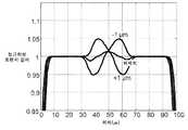
도 7a는 일 실시예에 따른 바람직한 플루엔스(fluence) 프로파일을 도식적으로 나타낸다.
도 7b는 일 실시예에 따른 도 7a의 바람직한 플루엔스 프로파일에 대응하는 최적화된 래스터 진폭들을 도식적으로 나타낸다.
도 8은 일 실시예에 따른 예시적 AOD 갤보 에러 교정 필터와 연계된 곡선들을 도식적으로 나타낸다.
도 9는 일 실시예에 따른 갤보 서브시스템의 보조 센서를 포함하는 레이저 처리 시스템의 블록도이다.
도 10은 특정 실시예에 따른 레이저 직접 융제를 위해 처리된 예시적 트렌치 패턴들을 예시하는 개략도이다.
도 11은 일 실시예에 따른 AOD 및 갤보 조화(coordination)와 연계된 곡선들을 도식적으로 나타낸다.
도 12는 일 실시예에 따른 AOD 속도 보상과 연계된 곡선들을 도식적으로 나타낸다.
도 13은 일 실시예에 따른 병렬 처리 및 영역 결합을 개략적으로 나타낸다.
도 14는 일 실시예에 따른 제3 프로파일링 서브시스템을 개략적으로 예시한다.
도 15a, 도 15b, 도 15c, 도 15d 및 도 15e는 일 실시예에 따른 도 14에 도시된 제3 프로파일링 서브시스템에 의해 생성 및/또는 사용되는 신호들을 예시한다.
도 16a, 도 16b 및 도 16c는 특정 실시예들에 다른 예시적 AOD 명령 시퀀스들을 예시한다.
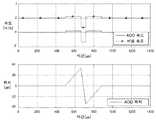
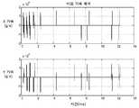
도 17a 및 도 17b는 특정 실시예들에 따른 속도 변조의 예들을 도식적으로 예시한다.
도 18은 일 실시예에 따른 위치 명령 신호에 관한 위치설정 에러 및 결과적인 AOD 위치 프로파일을 도식적으로 예시한다.
도 19는 일 실시예에 따른 래스터 조명을 위한 AOD 서브시스템을 사용한 렌즈 관통(through-the-lens)용 시스템의 블록도이다.
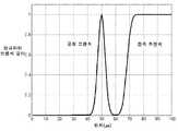
도 20은 예시적 실시예에 따른 AOD 회절 효율 곡선들을 도식적으로 나타낸다.
도 21은 예시적 실시예에 따른 추가적 AOD 선형화 곡선들을 도식적으로 나타낸다.
도 22는 일 실시예에 따른 AOD 제어 데이터 유동을 나타내는 블록도이다.
도 23은 일 실시예에 따른 교차부에서 접촉 트렌치(butting trench)의 접근을 도식적으로 나타낸다.
도 24는 일 실시예에 따른 도 23에 도시된 충돌 및 공칭 트렌치들의 단면 프로파일을 도식적으로 나타낸다.
도 25는 일 실시예에 따른 가우스 비임들과의 최적의 교차부를 도식적으로 나타낸다.
도 26은 일 실시예에 따른 도 25에 도시된 가우스 비임들과의 최적의 교차의 단면 프로파일을 도식적으로 나타낸다.
도 27은 일 실시예에 따른 교차 이전의 디더 트렌치들을 도식적으로 나타낸다.
도 28은 일 실시예에 따른 도 27에 도시된 디더를 갖는 공칭 및 접촉 트렌치들의 단면 프로파일을 도식적으로 나타낸다.
도 29는 일 실시예에 따른 디더 비임들과의 최적의 교차를 도식적으로 나타낸다.
도 30은 일 실시예에 따른 도 29에 대응하는 디더 비임들(최적 + 감도)을 갖는 교차부 단면을 도식적으로 나타낸다.
도 31은 일 실시예에 따른 개선된 위치 공차(교차 이전)를 위한 넓은 전이 에지를 도식적으로 나타낸다.
도 32는 일 실시예에 따른 도 31에 도시된 넓은 전이 트렌치들(교차 이전)을 갖는 공칭 및 접촉 트렌치들의 단면 프로파일을 도식적으로 나타낸다.
도 33은 일 실시예에 따른 넓은 전이 에지를 갖는 최적의 교차부를 도식적으로 나타낸다.
도 34는 일 실시예에 따른 도 33에 대응하는 넓은 전이부(최적 + 감도)를 갖는 교차 단면을 도식적으로 나타낸다.
도 35는 일 실시예에 따른 절결부를 갖는 교차된 교차 트렌치를 도식적으로 나타낸다.
도 36은 일 실시예에 따른 도 35에 도시된 절결된 트렌치의 단면 프로파일을 도식적으로 나타낸다.
도 37은 일 실시예에 따른 최적으로 교차된 교차부를 도식적으로 나타낸다.
도 38은 일 실시예에 따른 도 37에 대응하는 넓은 전이부(최적 + 감도)를 갖는 교차부 단면을 도식적으로 나타낸다.
도 39는 일 실시예에 따른 교차 트렌치들을 갖도록 처리된 "T" 교차부를 도식적으로 나타낸다.
도 40은 일 실시예에 따른 교차부들에서 투여량 및 형상 제어의 역학을 도식적으로 나타낸다.1 is a block diagram illustrating the operation of an AOD that can be used according to certain embodiments.
2 schematically shows the RF power for AOD diffraction efficiency curves at various RF frequencies that can be used according to certain embodiments.
3 schematically illustrates an exemplary AOD power linearization curve used to select a desired attenuation according to one embodiment.
4 schematically shows the RF frequency for AOD diffraction efficiencies that can be used to select a compromise between diffraction efficiency and deflection range according to certain embodiments.
5 is a block diagram of a system including an AOD subsystem and a galvo subsystem for dithering a laser beam according to one embodiment.
5A is a block diagram of a system for beam forming according to one embodiment.
5B is a block diagram of a system for providing tilted processing beams according to one embodiment.
6 is a flow diagram of a method of using a least squares optimization routine to determine a set of spot amplitudes across a grid of raster points according to one embodiment.
7A schematically illustrates a preferred fluence profile according to one embodiment.
7B schematically shows optimized raster amplitudes corresponding to the preferred fluence profile of FIG. 7A according to one embodiment.
8 schematically shows curves associated with an exemplary AOD galvo error correction filter according to one embodiment.
9 is a block diagram of a laser processing system including an auxiliary sensor of a galvo subsystem according to one embodiment.
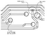
10 is a schematic diagram illustrating exemplary trench patterns processed for laser direct ablation according to a particular embodiment.
11 schematically illustrates curves associated with AOD and galvo coordination according to one embodiment.
12 schematically shows curves associated with AOD speed compensation according to one embodiment.
13 schematically illustrates parallel processing and region combining according to an embodiment.
14 schematically illustrates a third profiling subsystem according to one embodiment.
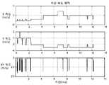
15A, 15B, 15C, 15D, and 15E illustrate signals generated and / or used by the third profiling subsystem shown in FIG. 14 according to one embodiment.
16A, 16B, and 16C illustrate example AOD command sequences that are different to certain embodiments.
17A and 17B schematically illustrate examples of speed modulation according to certain embodiments.
18 schematically illustrates a positioning error and a resulting AOD position profile for a position command signal according to one embodiment.
19 is a block diagram of a system for through-the-lens using an AOD subsystem for raster illumination according to one embodiment.
20 schematically shows AOD diffraction efficiency curves according to an exemplary embodiment.
21 schematically shows additional AOD linearization curves according to an exemplary embodiment.
22 is a block diagram illustrating AOD control data flow according to an embodiment.
23 schematically illustrates the approach of a butting trench at an intersection according to one embodiment.
24 schematically illustrates a cross-sectional profile of the collision and nominal trenches shown in FIG. 23 according to one embodiment.
25 schematically shows an optimal intersection with Gaussian beams according to one embodiment.
26 schematically illustrates a cross-sectional profile of an optimal crossover with the Gaussian beams shown in FIG. 25 according to one embodiment.
27 schematically shows dither trenches before crossover according to one embodiment.
28 schematically shows a cross-sectional profile of nominal and contact trenches with dither shown in FIG. 27 according to one embodiment.
29 schematically illustrates an optimal intersection with dither beams according to one embodiment.
FIG. 30 schematically shows a cross section of a cross section with dither beams (optimal + sensitivity) corresponding to FIG. 29 according to one embodiment.
31 schematically shows a wide transition edge for improved position tolerance (before crossing), according to one embodiment.
FIG. 32 schematically shows a cross-sectional profile of nominal and contact trenches with wide transition trenches (before crossing) shown in FIG. 31 according to one embodiment.
33 schematically illustrates an optimal intersection with a wide transition edge, according to one embodiment.
FIG. 34 schematically illustrates a cross section with a wide transition (optimal + sensitivity) corresponding to FIG. 33 according to one embodiment.
35 schematically illustrates an intersecting cross trench with cutouts according to one embodiment.
36 schematically illustrates a cross-sectional profile of the cut trench shown in FIG. 35 according to one embodiment.
37 schematically shows an optimally crossed intersection according to one embodiment.
38 schematically illustrates a cross section of a cross section with a wide transition (optimal + sensitivity) corresponding to FIG. 37 according to one embodiment.
39 schematically shows a “T” intersection processed to have crossing trenches according to one embodiment.
40 schematically illustrates the dynamics of dose and shape control at intersections according to one embodiment.
본 명세서에 개시된 실시예는 경제적이고 실현가능한 유연한, 고속 비임 위치설정 및 상태조정을 제공한다. 본 내용은 선형 위치설정 스테이지들 및/또는 갤보들과 조합한 AOD들의 사용을 설명한다.The embodiments disclosed herein provide economical, feasible, flexible, high-speed beam positioning and conditioning. This article describes the use of AODs in combination with linear positioning stages and / or galvos.
본 명세서에 개시된 예시적 실시예들은 AOD들에 관한 것이지만, 전자-광학 편향기들(EODs)도 사용될 수 있다. 특정 실시예들에서, 예로서, EOD들은 일부 또는 모든 AOD 포인팅(편향) 기능들을 위한 적절한 대체물들이다. EOD들(각도 편향을 위한 구성시)은 통상적으로 파워를 변조하지 않는다. 따라서, 특정 실시예들에서, 하나 이상의 AOD들이 파워 변조를 위해 사용되고, 하나 이상의 EOD들이 포인팅을 위해 사용된다. 변조를 수행하는 음향-광학 장치들은 음향-광학 변조기들(AOMs)로서 여기에서 지칭될 수 있다. 급속 조종 거울들(FSMs) 같은 다른 기계적 비임 조종 기술들은 기능성의 손실 없이 갤보 비임 위치설정 서브시스템을 대체할 할 수 있다.Although the exemplary embodiments disclosed herein relate to AODs, electro-optical deflectors (EODs) may also be used. In certain embodiments, as an example, EODs are suitable replacements for some or all AOD pointing (deflection) functions. EODs (when configured for angle deflection) typically do not modulate power. Thus, in certain embodiments, one or more AODs are used for power modulation and one or more EODs are used for pointing. Acoustic-optical devices that perform modulation may be referred to herein as acoustic-optical modulators (AOMs). Other mechanical beam steering techniques, such as fast steering mirrors (FSMs), can replace the galvo beam positioning subsystem without loss of functionality.
이하에 상세히 설명된 특정 실시예에 따른 레이저 처리 시스템은 AOD 및 갤보 위치설정 양자 모두를 제공한다. AOD 및 갤보 비임 위치설정을 포함하는 시스템은 원하는 작동 조건을 위해 파워 선형화 곡선들을 맞춤화함으로써 AOD로부터 높은 회절 효율에 대해 더 큰 편향 범위를 절충시키는 기능을 제공할 수 있다.The laser processing system according to the specific embodiment described in detail below provides both AOD and galvo positioning. Systems comprising AOD and galvo beam positioning can provide the ability to trade off a larger deflection range for high diffraction efficiency from AOD by customizing power linearization curves for the desired operating conditions.
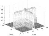
특정 실시예들은 작업편의 맞춤화된 처리를 위해 선택된 강도 프로파일을 생성하도록 AOD 편향 명령들을 급속 갱신함으로써 처리 비임의 디더링을 제공한다. 디더링은 처리 비임의 유효 치수들(예를 들어, 그 폭 또는 단면 형상)을 변화시키기 위해 또는 성형을 통한 것 같은 용례들을 위한 맞춤화된 스팟 강도 프로파일(임의의 형상의 상단-햇 강도 프로파일들)들을 생성하기 위해 사용될 수 있다. 디더링은 예로서, 교차부의 부분들의 과노출에 기인한 부적합한 깊이 변동을 피하면서 작업편 상에 교차하는 융제 특징부들을 생성하기 위해 사용될 수 있다. 본 명세서에 개시된 교차 처리 기능성들은 연속적 처리(중단 없이 주 특징부들을 처리하면서 비임 강도 프로파일을 성형) 또는 래스터 접근을 사용한 맞춤 처리 중 어느 하나를 가능하게 하며, 이는 다른 방식에서는 진행중인 처리를 불가능하게 하거나 곤란하게 할 수 있는 임의적 형상의 교차부들을 생성하기 위한 기능을 제공한다.Certain embodiments provide for processing beam dithering by rapidly updating AOD deflection commands to generate a selected intensity profile for customized processing of the workpiece. Dithering provides customized spot strength profiles (top-hat strength profiles of arbitrary shape) for applications such as through molding or to change the effective dimensions of the treatment beam (eg, its width or cross-sectional shape). Can be used to generate Dithering can be used, for example, to create crossover flux features on the workpiece while avoiding unsuitable depth variations due to overexposure of portions of the intersection. The cross-processing functionalities disclosed herein enable either continuous processing (forming the beam strength profile while processing the main features without interruption) or custom processing using a raster approach, which would otherwise disable ongoing processing or Provides the ability to create randomly shaped intersections that can be difficult.
AOD 및 갤보 위치설정을 갖는 시스템은 또한 원하는 교차부를 적절히 형성하도록 래스터 패턴(처리 비임 지점들의 위치 및 강도)을 최적화하는 것을 제공할 수도 있다. 또한, 특정 실시예들은 바람직하지 못한 노이즈를 동시에 필터링하면서 선택된 주파수 범위에 걸쳐 갤보 에러로부터의 위상 및 이득 응답을 비임 위치에 정합시키기 위해 갤보 에러 신호들을 적절히 필터링함으로써 갤보 위치설정 에러를 위한 교정을 제공한다. 디더링을 위한 대안적 접근법에서, 특정 실시예들은 펄스-펄스 기반으로 비임을 집속해제하기 위해 AOD 음향 파형을 "처핑(chirping)"함으로써 처리 비임 스팟 크기의 변경을 제공한다.Systems with AOD and galvo positioning may also provide for optimizing raster patterns (position and intensity of treatment beam points) to properly form the desired intersection. In addition, certain embodiments provide correction for galvo positioning errors by properly filtering the galvo error signals to match the phase and gain response from the galvo error to the beam location over the selected frequency range while simultaneously filtering out undesirable noise. do. In an alternative approach for dithering, certain embodiments provide a change in processing beam spot size by "chirping" the AOD acoustic waveform to defocus the beam on a pulse-pulse basis.
추가로, 또는 다른 실시예들에서, 갤보 비임 위치설정기들의 동작은 AOD 위치설정의 동작과 조화됨으로써 AOD들이 고 대역폭 궤적 구성요소들을 위해 처리 비임을 편향시킬 수 있게 하고, 갤보들이 별개의 프로파일링 명령들 또는 주 비임 궤적 명령들의 필터링 중 어느 하나를 통해 더 낮은 대역폭 구성요소들을 위해 비임을 편향시킬 수 있게 한다. 갤보 속도를 변화시키지 않으면서 고속 비임 궤적들은 AOD들이 작은 국지적 영역으로 비임 속도를 감소시킬 수 있게 함으로써 가능화되고, 이는 전체 속도에서 더 큰 국지적 특징부들의 처리를 가능하게 한다. 유사하게, 특징부 처리(비임 속도에 독립적인) 동안 일정한 투여량을 유지하기 위한 처리 비임 파워의 변조는 특정 섹션들에서 전체 속도로 갤보들이 이동할 수 있게 하고, 궤적의 더 양호한 추적을 위해 다른 섹션들에서 더 낮은 속도들로 신속하게 감속될 수 있게 한다.Additionally, or in other embodiments, the operation of the galvo beam locators is coordinated with the operation of the AOD positioning to allow the AODs to deflect the processing beam for high bandwidth trajectory components, and the galvos to separate profiles. Filtering of ring commands or primary beam trajectory commands allows the beam to be biased for lower bandwidth components. High-speed beam trajectories without changing the galvo speed are made possible by allowing the AODs to reduce the beam speed to a small local area, which allows processing of larger local features at full speed. Similarly, modulation of the treatment beam power to maintain a constant dose during feature processing (independent of beam speed) allows galvos to move at full speed in certain sections, and for better tracking of trajectories. It allows the sections to decelerate quickly at lower speeds.
특정 실시예들에서, 다수의 작업편 특징부들이 병렬로 처리되어(특징부들 사이에서 디더링하는 AOD들을 사용하여) 비임 위치설정기 속도를 감소시키면서 병렬 처리를 통한 더 높은 처리량을 가능하게 한다. AOD들에 의해 제공되는 교차 처리 기능들은 병렬로 처리되지 않는 인접 섹션들에 병렬로 처리되는 작업편 특징부들의 부분들을 결합시키기 위해 사용될 수 있다.In certain embodiments, multiple workpiece features are processed in parallel (using AODs dithering between features) to enable higher throughput through parallel processing while reducing beam positioner speed. The cross-processing functions provided by AODs can be used to combine portions of workpiece features that are processed in parallel to adjacent sections that are not processed in parallel.
또한, AOD들은 선택된 작업편 특징부의 속도 벡터를 따라 비임 위치를 디더링시키도록 AOD들을 사용함으로써 작업편 처리 동안 플룸 형성의 부적합한 효과들을 피하기 위해 및/또는 광학 트레인의 미소한 추가적 비용 또는 복잡성으로 비임 지터를 안정화하기 위해 사용될 수도 있다. 또한, AOD들이 작업편에 대한 정렬 및 그 렌즈 관통 관찰을 위한 필드 조명 및 기준 처리 비임 스팟을 동시에 제공함으로써 매우 높은 정확도로 작업편 특징부들에 처리 비임을 정렬시키기 위한, 그리고, 처리 비임에 대한 초점 정렬을 최적화하기 위한 기능을 (미소한 여분의 비용 또는 복잡성으로) 제공하기 위해 사용될 수도 있다. AOD들은 열의 영향을 받은 구역 효과들이 최소화되도록 프로세스 비임의 듀티 사이클을 맞춤 조정할 수 있는 기능을 또한 제공할 수 있다.In addition, AODs use beams to dither beam positions along the velocity vector of the selected workpiece feature to avoid inappropriate effects of plume formation during workpiece processing and / or beam jitter with a minor additional cost or complexity of the optical train. It can also be used to stabilize. In addition, the AODs simultaneously provide field illumination and reference treatment beam spots for alignment to the workpiece and observing its lens, thereby aligning the treatment beam to the workpiece features with very high accuracy, and focus on the treatment beam It can also be used to provide the ability to optimize alignment (with minimal extra cost or complexity). AODs can also provide the ability to tailor the duty cycle of the process beam to minimize heat-affected zone effects.
이제, 유사 참조 번호들이 유사 구성요소들을 나타내고 있는 도면들을 참조한다. 명료성을 위해, 참조 번호의 첫 자리는 대응 구성요소가 최초 사용되는 도면 번호를 나타낸다. 후속 설명에서, 다수의 특정 세부사항들은 본 명세서에 개시된 실시예들의 전반적 이해를 위해 제공되어 있다. 그러나, 본 기술 분야의 숙련자들은 특정 세부사항들 중 하나 이상 없이 또는 다른 방법들, 구성요소들 또는 재료들로 실시될 수 있다는 것을 알 수 있을 것이다. 또한, 일부 경우들에서, 잘 알려진 구조들, 재료들 또는 동작들은 본 발명의 양태들을 불명료하게 하는 것을 피하기 위해 상세히 도시 또는 설명되어 있다. 또한, 설명된 특징부들, 구조들 또는 특징들은 하나 이상의 실시예들에서 임의의 적절한 방식으로 조합될 수 있다.Reference is now made to the figures in which like reference numbers indicate like elements. For the sake of clarity, the first digit of the reference number indicates the drawing number in which the corresponding component is first used. In the following description, numerous specific details are provided for a general understanding of the embodiments disclosed herein. However, one skilled in the art will appreciate that it may be practiced without one or more of the specific details or with other methods, components, or materials. Also, in some cases, well-known structures, materials, or operations are shown or described in detail to avoid obscuring aspects of the invention. Further, the described features, structures or features can be combined in any suitable way in one or more embodiments.
실시예들은 다양한 단계들을 포함할 수 있으며, 이는 범용 목적 또는 특수 목적 컴퓨터(또는 다른 전자 장치)에 의해 실행되는 기계 실행가능 명령들로 구현될 수 있다. 대안적으로, 단계들은 단계들을 수행하기 위한 특정 로직을 포함하는 하드웨어 구성요소들 또는 하드웨어, 소프트웨어 및/또는 펌웨어의 조합에 의해 수행될 수 있다.Embodiments can include various steps, which can be implemented with machine-executable instructions executed by a general purpose or special purpose computer (or other electronic device). Alternatively, the steps can be performed by hardware components that include specific logic to perform the steps or a combination of hardware, software and / or firmware.
또한, 실시예들은 본 명세서에 설명된 처리들을 수행하도록 컴퓨터(또는 다른 전자 장치)를 프로그램하기 위해 사용될 수 있는 명령들이 저장되어 있는 비-일시적, 기계 판독가능 매체를 포함하는 컴퓨터 프로그램 제품으로서 제공될 수 있다. 기계 판독가능 매체는 하드 드라이브들, 플로피 디스켓들, 광학 디스크들, CD-ROM들, DVD-ROM들, ROM들, RAM들, EPROM들, EEPROM들, 자기 또는 광학 카드들, 고상 메모리장치들 또는 전자 명령들을 저장하기에 적합한 다른 유형의 매체/컴퓨터 판독가능 매체를 포함하지만 이에 한정되지 않을 수 있다.In addition, the embodiments are to be provided as a computer program product comprising a non-transitory, machine readable medium storing instructions that can be used to program a computer (or other electronic device) to perform the processes described herein. You can. Machine-readable media include hard drives, floppy diskettes, optical disks, CD-ROMs, DVD-ROMs, ROMs, RAMs, EPROMs, EEPROMs, magnetic or optical cards, solid state memory devices or Other types of media / computer readable media suitable for storing electronic instructions include, but are not limited to.
I. AOD 개요I. AOD Overview
도 1은 특정 실시예들에 따라 사용될 수 있는 AOD(100)의 동작을 예시한다. AOD(100)는 결정(crystal)(112)에 결합된 압전 트랜스듀서(110)를 포함한다. AOD(100)는 결정(112) 내에 RF 주파수 음향 웨이브(114)(예를 들어, 약 50 MHz와 약 1500 MHz 사이의 주파수 범위에서)를 생성하기 위해 압전 트랜스듀서(110)를 구동하도록 구성된 라디오 주파수(RF) 구동부(113)를 더 포함한다. 입사 레이저 비임(115)은 결정(112)에 구성된 음향 웨이브(114)에 의해 회절되며, 입력 비임 파워의 일부는 편향되며("1차" 비임(116)) 및 파워의 잔여부는 편향되지 않는다("0차" 비임(118)). 일부 실시예들에서, 1차 비임(116)은 처리를 위해 사용되고, 0차 비임은 비임 덤프(122)로 전송된다. 1차 편향 각도(120)는 인가된 RF 주파수에 비례한다.1 illustrates the operation of
일 실시예에서, 음향 웨이브 컬럼에 대한 입사 비임 각도는 브랙(Bragg) 각도로 설정된다. 입사 비임 각도를 브랙 각도로 설정하는 것은 회절 효율을 증가시키거나 최대화하며, 이는 입력 비임 파워에 대한 1차 비임 파워의 비율이다. 1차 비임(116) 내로 편향된 상대적 파워는 낮은 RF 파워 레벨들에서 RF 구동부(113)에 의해 인가되는 RF 파워에 대략 비례할 수 있다. 그러나, 1차 비임(116)으로 편향된 상대적 파워는 높은 레벨로 포화될 수 있다(예를 들어, 도 2에 도시된 바와 같이). 실제 작동에서, 소량의 파워는 또한 더 높은 차수의 비임들(미도시)로 편향되거나 산란될 수도 있다.In one embodiment, the angle of incidence beam for the acoustic wave column is set to the Bragg angle. Setting the incident beam angle to the Bragg angle increases or maximizes the diffraction efficiency, which is the ratio of the primary beam power to the input beam power. The relative power deflected into the
AOD들의 회절 효율들은 선택된 RF 주파수 및 진폭에서 양호한(고품질 가우스) 입력 비임을 갖는 적절히 설계된 장치를 위해 대략 95% 이상까지의 범위에 걸쳐질 수 있다. RF 주파수가 변할 때, 편향된 비임 각도들은 변하며, 회절 효율은 그 최대값 미만으로 떨어진다. AOD들은 작업편(미도시)에서 집속된 스팟의 약 3 내지 5 직경과 같은 편향 범위에 걸쳐 약 90% 효율보다 크게 유지할 수 있다. 구체적으로, 설계된 AOD들은 RF 주파수의 함수로서 음향 비임 각도를 조정하는 기술들을 통한 매우 더 높은 회절 효율들을 달성할 수 있다.The diffraction efficiencies of AODs can span up to approximately 95% or more for a properly designed device with a good (high quality Gaussian) input beam at the selected RF frequency and amplitude. When the RF frequency changes, the deflected beam angles change, and the diffraction efficiency falls below its maximum value. AODs can maintain greater than about 90% efficiency over a deflection range, such as about 3 to 5 diameters of the spot focused on the workpiece (not shown). Specifically, designed AODs can achieve much higher diffraction efficiencies through techniques that adjust the acoustic beam angle as a function of RF frequency.
두 개의 AOD들은 이차원(2-D) 편향 서브시스템을 생성하도록 조합될 수 있다. 갤보들 이전에 배치될 때, 후술된 바와 같이, 두 개의 AOD들은 갤보들에 의해 생성된 공칭 비임 위치 둘레에 작은 비임 편향을 부여한다. 이런 배열은 예로서, 미국 특허 제5,837,962호에 설명되어 있다. 작업편을 처리하기 위해 이런 배열을 사용할 때, 특정 실시예들은 AOD 편향의 함수로서 회절 효율의 변화에도 불구하고 AOD 편향 동안 일정한 비임 파워를 유지한다. AOD 편향 동안 일정한 비임 파워를 유지하는 것은 RF 주파수의 함수로서 RF 파워 진폭을 갱신(예를 들어, 변조)함으로써 고속으로(예를 들어, 약 0.1 μs 내지 약 10 μs의 AOD들에 대해 사용되는 갱신율들에서) 달성될 수 있다. RF 파워 변조는 최저 회절 효율에 근사하거나 그와 일치하도록 AOD 편향 범위의 중간 부분의 회절 효율을 낮추는 효과를 갖는다. 최저 회절 효율을 정합시키는 것이 회절 서브시스템의 효율을 저하시키지만, 이는 AOD 편향 범위에 걸쳐 실질적으로 일정한(또는 예측가능한) 파워를 사용하는 용례들에 AOD들이 사용될 수 있게 한다.The two AODs can be combined to create a two-dimensional (2-D) bias subsystem. When placed before the galvos, as described below, the two AODs impart a small beam deflection around the nominal beam location created by the galvos. Such an arrangement is described, for example, in US Pat. No. 5,837,962. When using this arrangement to process a workpiece, certain embodiments maintain a constant beam power during AOD deflection despite changes in diffraction efficiency as a function of AOD deflection. Maintaining a constant beam power during AOD deflection is an update used for high-speed (e.g., about 0.1 μs to about 10 μs AODs) by updating (e.g., modulating) the RF power amplitude as a function of RF frequency. Rates). RF power modulation has the effect of lowering the diffraction efficiency in the middle of the AOD deflection range to approximate or match the lowest diffraction efficiency. Matching the lowest diffraction efficiency degrades the efficiency of the diffraction subsystem, but this allows AODs to be used in applications that use a substantially constant (or predictable) power across the AOD deflection range.
상술한 바와 같이, EOD들은 각도 편향 용례들을 위해 AOD들에 대한 대안으로서(또는 AOD들과 연계하여) 사용될 수 있다. EOD 편향기들은 제한된 범위(예를 들어, 작업편의 소수의 스팟 직경들과 등가인), 매우 높은 대역폭들(예를 들어, 마이크로초 응답 시간들) 및 높은 전송 효율로 AOD들에 유사한 기능들을 갖는다. 그러나, EOD 장치들을 구현하기 위해 사용되는 결정들은 비교적 높은 광학 파워 흡수(예를 들어, 수 퍼센트) 또는 현저한 전기적 파워 소산을 겪을 수 있으며, 이는 열적 렌싱 및/또는 비임 포인팅 드리프트의 문제들을 초래할 수 있다. 또한, 일부 실시예들(예를 들어, 낮은 광학 파워 및/또는 높은 전송 파장들을 사용하여)에서, AOD들을 사용하여 아래에 설명된 기술들이 EOD들에 의해 달성될 수 있다.As described above, EODs can be used as an alternative (or in conjunction with AODs) to AODs for angular deflection applications. EOD deflectors have similar functions to AODs with limited range (e.g., equivalent to a small number of spot diameters in the workpiece), very high bandwidths (e.g. microsecond response times) and high transmission efficiency. . However, the crystals used to implement EOD devices can suffer from relatively high optical power absorption (eg, several percent) or significant electrical power dissipation, which can lead to problems of thermal lensing and / or beam pointing drift. . Also, in some embodiments (eg, using low optical power and / or high transmission wavelengths), techniques described below using AODs can be achieved by EODs.
II. 파워 선형화II. Power linearization
특정 실시예들에 따른 레이저 처리 용례들에서 AOD들을 적절히 사용하기 위해, 회절 효율 곡선은 RF 파워 및 주파수의 함수로서 선형화된다. 예측가능한 동작을 위해, 정규화된 AOD 파워 감쇄 명령(0 내지 1의 범위)이 사용될 수 있으며, 이는 1차 비임 파워의 선형 감쇄를 초래한다. 도 2는 특정 실시예들에 따라 사용될 수 있는 다양한 RF 주파수들에서 AOD 회절 효율 곡선들 대 RF 파워를 도식적으로 나타낸다. 도 2에 도시된 바와 같이, AOD 회절 효율 곡선은 일반적으로 비선형적이다. 회절 효율 곡선들의 비선형 특성에 기인하여, 회절 효율 대 RF 파워가 특정 실시예들에 따라 맵핑될 수 있으며, 명령된 감쇄를 초래하는 RF 파워를 제공하는 선형화 함수(예를 들어, 다항식, 참조표 또는 유사 알고리즘)가 생성될 수 있다.In order to properly use AODs in laser processing applications according to certain embodiments, the diffraction efficiency curve is linearized as a function of RF power and frequency. For predictable operation, a normalized AOD power attenuation command (range from 0 to 1) can be used, resulting in a linear attenuation of the primary beam power. 2 schematically shows AOD diffraction efficiency curves versus RF power at various RF frequencies that can be used according to certain embodiments. As shown in Figure 2, the AOD diffraction efficiency curve is generally nonlinear. Due to the non-linear nature of the diffraction efficiency curves, the diffraction efficiency versus RF power can be mapped according to certain embodiments and provides a linearization function (e.g., polynomial, reference table or Pseudo-algorithm).
도 3은 일 실시예에 따른 원하는 감쇄를 선택하기 위해 사용되는 예시적 AOD 파워 선형화 곡선을 도식적으로 나타낸다. 도 3에 예시된 예시적 선형화 함수는 참조표 형태로 나타내질 수 있다. 도 3에 도시된 선형화 함수는 다양한 RF 주파수들을 위한 미소한 변동과 함께 특정 RF 주파수를 위해 유효하다. 적절한 RF 주파수(그리고, 이에 따른 편향) 범위에 걸친 선형 동작을 가능하게 하기 위해, 특정 실시예들은 복수의 선형화 표들을 사용한다. 선형화 표들의 수는 AOD에 적용되는 주파수 범위 및 파워 정규화가 유지되는 정밀도에 의존한다. 특정 실시예들에서, 선형화 표들은 약 1%의 공차 이내의 선형 파워 규제를 생성할 수 있다.3 schematically illustrates an exemplary AOD power linearization curve used to select a desired attenuation according to one embodiment. The exemplary linearization function illustrated in FIG. 3 may be represented in the form of a reference table. The linearization function shown in FIG. 3 is valid for a particular RF frequency with minor variations for various RF frequencies. To enable linear operation over a suitable RF frequency (and thus deflection) range, certain embodiments use multiple linearization tables. The number of linearization tables depends on the frequency range applied to the AOD and the precision with which power normalization is maintained. In certain embodiments, linearization tables can generate a linear power regulation within a tolerance of about 1%.
2-D AOD 구성에서, 단 하나의 AOD가 파워 선형화를 위해 RF 파워를 제어하기 위해 필요할 수 있다. 제1 AOD의 RF 파워의 변조는 제2 AOD의 회절 효율을 선형화하기 위해 사용되는 제어를 제공할 수 있다. 특정 이런 실시예들에서, 제2 AOD는 그 포화 지점 부근에서 동작하고, 여기서, RF 주파수의 변화들은 회절 효율에 최소의 영향을 가지며, 이는 편향의 함수로서 회절 효율 변동을 최소화 및 감소시킨다. 특정 실시예들에 필요한 경우, 두 개의 AOD들 중 어느 하나는 파워 선형화를 위해 사용될 수 있다. 특정 실시예들에서, 제1 AOD는 거친 파워 제어를 위해 사용될 수 있고, 제2 AOD는 양자화된 RF 파워 명령들에 의해 도입되는 선형화 에러들을 최소화 및 감소시키기 위해 미세 파워 제어를 위해 사용될 수 있다.In a 2-D AOD configuration, only one AOD may be needed to control the RF power for power linearization. Modulation of the RF power of the first AOD can provide control used to linearize the diffraction efficiency of the second AOD. In certain such embodiments, the second AOD operates near its saturation point, where changes in RF frequency have minimal effect on diffraction efficiency, which minimizes and reduces diffraction efficiency variations as a function of deflection. If necessary for certain embodiments, either of the two AODs can be used for power linearization. In certain embodiments, the first AOD can be used for coarse power control, and the second AOD can be used for fine power control to minimize and reduce linearization errors introduced by quantized RF power commands.
최적 RF 주파수 설정에서 회절 효율 곡선의 피크화에 기인하여, 다른 주파수들에서의 동작은 더 낮은 광학 효율로 AOD를 운용하는 것을 필요로 할 수 있다. AOD가 주어진 편향 범위에 걸쳐 일정한 광학 출력 파워로 동작되는 경우, 요구된 출력 파워는 전체 편향 범위에 걸쳐 최소 달성가능 출력 파워 미만으로 유지하도록 특정 실시예들에서 구성될 수 있다. 이러한 제약은 레이저 처리 시스템의 디자인에서 인식될 수 있으며, AOD의 동작 편향 범위의 선택을 안내할 수 있다. 매우 높은 광학 효율을 필요로 하는 처리들에 대하여, AOD는 작은 편향 범위(예를 들어, 약 5 스팟 직경들 미만) 이내에서 동작될 수 있다. 더 큰 편향 범위(예를 들어, 수백 스팟 직경들 까지)를 필요로하는 처리들에 대하여, 최대 효율은 사용자가 효율(예를 들어, 광학 파워) 대 편향 범위의 절충을 가능하게 하기 위해 감소될 수 있다. 예로서, 도 4는 특정 실시예들에 따른 편향 범위와 회절 효율 사이의 절충을 선택하기 위해 사용될 수 있는 AOD 회절 효율들 대 RF 주파수를 도식적으로 나타낸다. 도 4는 예시적 RF 주파수(편향 진폭) 동작 범위(412)를 위한, 회절 효율 응답 대 RF 주파수 이동 및 최소 회절 효율의 변화를 나타낸다. 작은 범위에 걸친 높은 효율은 화살표(414)로 도시되어 있으며, 더 큰 범위에 걸친 더 낮은 효율이 화살표(416)로 도시되어 있다.Due to the peaking of the diffraction efficiency curve at the optimal RF frequency setting, operation at different frequencies may require operating the AOD with lower optical efficiency. When the AOD is operated with a constant optical output power over a given deflection range, the required output power can be configured in certain embodiments to keep below the minimum achievable output power over the entire deflection range. These constraints can be recognized in the design of laser processing systems and can guide the selection of the operating deflection range of the AOD. For processes requiring very high optical efficiency, AOD can be operated within a small deflection range (eg, less than about 5 spot diameters). For processes that require a larger deflection range (eg, up to several hundred spot diameters), the maximum efficiency can be reduced to enable the user to trade off the efficiency (eg, optical power) versus deflection range. You can. As an example, FIG. 4 schematically shows the RF frequency versus AOD diffraction efficiencies that can be used to select a compromise between deflection range and diffraction efficiency according to certain embodiments. 4 shows the change in diffraction efficiency response versus RF frequency shift and minimum diffraction efficiency, for an exemplary RF frequency (deflection amplitude)
III. 디더링(Dithering)III. Dithering
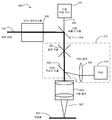
도 5는 일 실시예에 따른 레이저 비임을 디더링시키기 위한 갤보 서브시스템(508) 및 AOD 서브시스템(506)을 포함하는 시스템(500)의 블록도이다. 시스템(500)은 AOD 서브시스템(506)에 처리 비임(512)을 제공하기 위한 레이저 소스(510)를 포함한다. 일 실시예에서, 레이저 소스(510)는 처리 비임(512)이 일련의 레이저 펄스들을 포함하도록 펄스형 레이저 소스를 포함한다. 다른 실시예에서, 레이저 소스(510)는 처리 비임(512)이 CW 레이저 비임을 포함하도록 연속 파(CW) 레이저 소스를 포함한다. 특정 이런 실시예들에서, AOD 서브시스템(506)은 분리된("펄스") 간격들로 처리 비임(512)을 편향시킴으로써 CW 레이저 비임으로부터 레이저 펄스들을 생성한다.5 is a block diagram of a
상술한 바와 같이, AOD 서브시스템(506)은 AOD 편향 각도(514)에서 처리 비임(512)의 1차 비임(513) 및 처리 비임(512)의 0차 비임(515)을 비임 덤프(516)로 편향시킨다. 시스템(500)은 1차 비임(513)을 갤보 서브시스템(508)으로 편향시키기 위한 고정 거울(518) 및 작업편(524) 내에 또는 상에 레이저 비임 스팟(522)을 집속시키기 위한 스캔 렌즈(520)를 더 포함할 수 있다. 스캔 렌즈(520)의 출력은 본 명세서에서 집속된 레이저 비임(525)이라 지칭될 수 있다.As described above, the
일 실시예에서, AOD 서브시스템(506)은 갤보 시스템(508)이 처리 궤적(526)을 따른 제2 방향으로 편향을 제공하는 동안 제1 방향(예를 들어, 디더 방향)으로 전후 편향을 제공하기 위해 사용되는 단일 AOD를 포함할 수 있다. 그러나, 증가된 속도 및 다재성을 위해, 도 5에 예시된 실시예의 AOD 서브시스템(506)은 작업편(524)의 표면에 관하여 X 축 및 Y 축을 따른 2-D 편향을 제공한다. 본 예에서, Y 축은 처리 궤적(526)에 평행한 것으로 지칭될 수 있으며, X 축은 처리 궤적(526)에 수직인 것으로 지칭될 수 있다. 따라서, X 축은 디더 방향이라 지칭될 수 있다. 처리 궤적(526)은 예로서, 시스템(500)이 작업편(524)의 표면 내에 트렌치(528)를 새기거나 절삭하는(예를 들어, 갤보 서브시스템(508)의 제어 하에) 방향에 대응할 수 있다.In one embodiment,
예시된 2-D 편향을 제공하기 위해, AOD 서브시스템(506)은 갤보 서브시스템(508)이 처리 궤적(526)을 따라 비임 축을 이동시킬 때, 제1 방향으로 1차 비임(513)을 편향시키기 위한 제1 AOD(530)와, 제2 방향으로 1차 비임(513)을 편향시키기 위한 제2 AOD(532)를 포함한다. 달리 말하면, AOD 서브시스템(506)에 의해 제공되는 비임 스팟 위치들의 이동은 갤보 서브시스템(508)에 의해 제공되는 비임 스팟 위치들의 이동에 중첩된다. 도 5에 도시된 바와 같이, 갤보 서브시스템(508)은 또한 작업편(524)의 표면에 관하여 X 축 및 Y 축 방향들 양자 모두로 1차 비임(513)을 편향시키기 위한 제1 갤보 거울(533) 및 제2 갤보 거울(535)을 포함할 수 있다.To provide the illustrated 2-D deflection,
AOD 편향들의 배향은 갤보 서브시스템(508)의 편향 축들에 정렬되지 않을 수 있다. 일반적으로, 결과적 AOD 편향들을 원하는 좌표 프레임에 정렬시키기 위해 AOD 편향 명령들에 좌표 변환이 적용될 수 있다. 또한, 이 좌표 변환은 속도의 함수일 수 있으며, 갤보 서브시스템(508)에 의해 형성된 처리 궤적에 수직인 AOD 비임 편향을 유지하기 위해 AOD 편향 좌표 프레임을 회전시킨다.The orientation of the AOD deflections may not be aligned with the deflection axes of the
시스템(500)에 포함된 AOD 서브시스템(506)에 의해, 다수의 동작 모드들이 가능화된다. 일 실시예에서, 동작 모드는 작업편(524)에서 레이저 비임 스팟(522)을 효과적으로 확장시키기 위해 처리 비임(512)을 디더링시키는 기능을 포함한다. 달리 말하면, 처리 비임(512)을 디더링시키는 것은 스캔 렌즈(520)에 의해 집속된 개별 레이저 비임 스팟(522)의 것들보다 큰 치수들을 갖는 형상 특징부들을 생성하기 위해 일련의 집속된 레이저 비임 스팟들(534)을 공간적으로 위치시키는 것을 포함한다. 예시적 목적들을 위해, 도 5는 트렌치(528)가 처리 궤적(526)의 방향으로 처리될 때 작업편(524)의 표면 위로부터 볼 때 디더링된 레이저 비임 스팟들(534)을 나타낸다. 따라서, 예로서, 주어진 반복율의 일련의 디더링된 레이저 비임 스팟들(534)은 더 낮은 펄스 반복율에서 처리 궤적(526)의 방향으로 연속적으로 적용되는 일련의 더 큰 직경의 레이저 비임 스팟들의 영향을 갖는다.By the
특정 실시예들에서, AOD들(530, 532)은 약 0.1 μs 내지 약 10 μs 정도로 그 반복적 음향 필드들(새로운 음향 파형을 갖는 광학 개구를 채우는)을 갱신시킬 수 있다. 약 1 μs의 공칭 갱신율을 가정하면, 처리 비임의 위치는 처리 동안 다수의 디더 레이저 비임 스팟들(534)이 중첩하도록 반복적으로 갱신될 수 있다. 디더 레이저 비임 스팟들(534)은 처리되는 특징부(예를 들어, 트렌치(528))를 확장시키기 위해 처리 궤적(526)에 수직인 차원(예를 들어, X 축 또는 디더 방향을 따라)에서 중첩될 수 있다. 도 5에 도시된 바와 같이, 디더 레이저 비임 스팟들(534)은 또한 처리 궤적(526)의 방향으로 중첩할 수 있다. 특정 실시예들에 따른 처리 궤적(526)에 수직으로 배향된 디더 비임을 유지하기 위해, 디더 축은 처리 궤적(526)의 각도가 변할 때 일정하게 조절될 수 있다. 추가적으로, 디더 축은 처리 궤적 속도의 함수로서 디더 지점의 라인에 부여된 각도를 보상하도록 조절될 수 있다. 궤적 속도(V), 디더 갱신 주기(Td), 다수의 디더 지점들(Npts) 및 디더 편위(Dd)가 주어지면, 이 각도는 atan[Td*(Npts-1)*V/Dd]와 같다.In certain embodiments,
작업편(524)의 표면에 관하여 비임 위치를 디더링시키는 것에 추가로, 또는, 다른 실시예들에서, AOD 서브시스템(506)은 디더 축의 강도 프로파일을 변화시키도록 사용될 수 있다. 디더 축을 따른 처리 비임(512)의 강도 프로파일의 조작은 처리된 트렌치(528)의 단면의 성형을 가능하게 한다. 예로서, 트렌치(528)는 직사각형, U 또는 V 형 단면들로 처리될 수 있다. 측벽 경사 같은 특징부들의 성형은 교차부 형성 같은 상황들에 유용할 수 있다. 성형 해상도는 기본적 스팟 크기에 기초할 수 있으며, 성형된 강도 프로파일은 스팟 강도 프로파일(예를 들어, 가우스 또는 다른 프로파일 형상)과 디더 패턴(위치 및 강도)의 콘볼루션일 수 있다. 특징부는 예로서, 선택된 양의 타겟 재료를 제거하기 위해 디더 축을 따라 특정 위치들(예를 들어, 둘 이상의 펄스들이 동일 위치에 인가될 수 있음)에서 펄스들을 중첩시킴으로써 및/또는 디더 축을 따라 편향 위치의 함수로서 레이저 펄스들의 파워 진폭들을 변조시킴으로써 성형될 수 있다.In addition to dithering the beam position relative to the surface of the
디더 축을 따른 특징부의 성형에 추가로 또는 다른 실시예들에서, AOD 서브시스템(506)은 처리된 선형 특징부의 "종점"의 유사한 성형을 가능하게 하도록 처리 궤적(526)을 따른 위치의 함수로서 파워를 제어하기 위해 사용될 수 있다. 처리 궤적(526)을 따른 위치의 함수로서 파워를 제어하는 것은 또한 교차부 형성 같은 용례들에 유용할 수 있다. AOD 서브시스템(506)의 사용은 강도 프로파일들(예를 들어, 약 5 ㎛과 약 50 ㎛ 사이의 범위의 특징부 치수들을 가짐)의 미세 제어가 높은 처리 속도들(예를 들어, 약 1 m/s와 약 5 m/s 사이의 범위)에서 가능하도록 매우 높은 속도들(예를 들어, 마이크로초 정도)에서 파워 변조가 이루어질 수 있게 한다.In addition to or in other embodiments, shaping of the feature along the dither axis, the
가우스 비임들의 편향에 추가로, 특정 실시예들은 또한 예로서, 회절 광학 구성요소들(DOEs)을 포함하는 전형적 비임 성형 기술들에 의해 성형된 비임을 편향시킬 수 있다. 예로서, 도 5a는 일 실시예에 따른 비임 성형을 위한 시스템(540)의 블록도이다. 시스템(540)은 도 5에 도시된, AOD 서브시스템(506)(제1 AOD(530) 및 제2 AOD(532)를 구비), 0차 비임 덤프(516) 및 거울(518)을 포함한다. 시스템(540)은 비임 성형 및 광학 구성요소들(544)(예를 들어, 이미징 광학장치, 갤보 거울들 및 스캔 렌즈)을 위한 회절 광학 구성요소(DOE)(542)를 추가로 포함한다. 예시적 목적들로, 도 5a의 1차 비임(513)은 AOD 편향 각도들(514)의 범위에 걸쳐 도시되어 있다. 도 5a에 예시된 실시예에서, AOD 서브시스템(506)에 의해 편향된 1차 비임(513)은 AOD 서브시스템(506)에 의해 부여되는 AOD 편향 각도(514)에 무관하게 DOE의 개구에 중심설정된 1차 비임(513)을 유지하기 위해 중계 렌즈(546)(비임의 피봇 지점을 DOE(542) 상에 이미징)를 통해 DOE(542)에 중계된다. DOE(542)는 그후 추가적 웨이브프론트 위상 왜곡(이런 비임 성형 DOE들에 통상적인 바와 같은)을 부여함으로써 비임 강도를 성형할 수 있다. 이 접근법은 레이저 성형 비임들이 편향되고 예로서, 스퀘어 강도 프로파일들을 갖는 더욱 균일한 디더 플루엔스 프로파일을 형성하도록 인접될 수 있는 상황들에서 유익할 수 있다. 이 접근법은 또한 원하는 특징부(예로서, 유전체 재료에 천공된 마이크로비아)를 형성하기 위해 소수의 레이저 펄스들이 적합한 상황들에 유익할 수도 있다. 이 경우에, 가우스 펄스들의 래스터 용례는 성형된 강도 프로파일을 적용하는 것에 비해 비효율적일 수 있으며, 오히려, 고속 AOD 편향이 성형된 강도 처리 스팟 위치의 고속 제어에 바람직할 수 있다.In addition to deflection of Gaussian beams, certain embodiments may also deflect beams shaped by typical beam forming techniques, including, for example, diffractive optical components (DOEs). As an example, FIG. 5A is a block diagram of a
다른 실시예들에서, 유사한 중계 렌즈 구성은 스캔 렌즈에서 AOD 편향 비임의 편향을 맞춤화하기 위해 사용될 수 있다. 이는 적어도 두 가지 이유들 때문에 바람직할 수 있다. 먼저, (a) 비임 크립핑을 피하도록 스캔 렌즈 및 갤보 거울들의 투명 개구에 중심설정된 비임을 유지하고, (b) 스캔 렌즈 입사 동공의 중심으로부터 비임을 변위시키는 것을 피하도록 갤보 스캔 거울들로 피봇 지점을 중계(비임 측방향 편향의 제거)하는 것이 바람직할 수 있으며, 그 이유는 이런 변위가 작업표면에 경사 비임을 생성할 수 있기 때문이다. 두 번째로, 작업 표면에서 비임을 의도적으로 생성하기 위해 스캔 렌즈에 측방향 비임 편향을 부여하는 것이 바람직할 수 있다. 경사 비임은 처리된 특징부들(예로서, 마이크로비아 천공) 내에 급준한 측벽을 생성하기 위해 특정 가우스 레이저 천공 용례들에 유리할 수 있다.In other embodiments, a similar relay lens configuration can be used to tailor the deflection of the AOD deflection beam in the scan lens. This can be desirable for at least two reasons. First, (a) keep the beam centered in the transparent opening of the scan lens and galvo mirrors to avoid beam creeping, and (b) pivot into the galvo scan mirrors to avoid displacing the beam from the center of the scan lens incidence pupil It may be desirable to relay the point (removal of beam lateral deflection), since this displacement can create an inclined beam on the working surface. Second, it may be desirable to impart lateral beam deflection to the scan lens to intentionally create the beam at the working surface. Inclined beams can be advantageous for certain Gaussian laser drilling applications to create steep sidewalls within treated features (eg, microvia drilling).
도 5b는 일 실시예에 따른 경사 처리 비임들(552)을 제공하는 시스템(550)의 블록도이다. 시스템(550)은 AOD 서브시스템(506)(제1 AOD(530) 및 제2 AOD(532)), 0차 비임 덤프(516) 및 도 5에 도시된 거울(518)을 포함한다. 시스템(550)은 중계 렌즈(546) 및 광학 구성요소들(544)(예를 들어, 이미징 광학장치, 갤보 거울들 및 스캔 렌즈)을 더 포함한다. 예시적 목적들로, 도 5b의 1차 비임(513)이 AOD 편향 각도들(514)의 범위에 걸쳐 도시되어 있다. 도 5b에 도시된 바와 같이, 스캔 렌즈로부터(예를 들어, 도 5에 도시된 스캔 렌즈(520)로부터) 중계 렌즈(546)를 적절히 설계하고 간격을 둠으로써(554), AOD 서브시스템(506)에 의해 편향된 1차 비임(513)은 또한 작업편(524)의 표면에서 경사 비임(552)을 생성하도록 측방향으로 편향될 수도 있다. 작업편(524)에서 처리 스팟의 주어진 편향을 위해 비임 경사의 양은 (a) 작업편(524)에서 측방향 스팟 편향을 실질적으로 생성하기 위해 AOD들(530, 532)을 사용하고 스캔 렌즈(예를 들어, 스캔 렌즈(520))으로 중계 렌즈(546) 광학장치 및 간격(554)을 변화시키거나, (b) 스캔 렌즈에서의 임의적 측방향 비임 편향(그리고, 이에 따른 작업편(524)에서의 임의적 비임 경사)이 작업편(524)에서 바람직한 측방향 스팟 편향으로부터 독립적으로 부여될 수 있도록 갤보들(예를 들어, 도 5에 도시된 갤보들(533, 535)) 및 AOD들(530, 532)을 조화시킴으로써 제어될 수 있다.5B is a block diagram of a
또한, 성형 기술들의 세부사항들은 "예시적 AOD 제어 실시예들"이란 명칭의 장에서 이하에 설명되어 있다.In addition, details of the molding techniques are described below in the chapter entitled “Example AOD Control Embodiments”.
비임 디더링이 원하는 플루엔스 프로파일을 생성하기에 매우 효과적이고 유연할 수 있지만, 디더링을 위한 대안적(그러나, 때때로 더욱 제한적인) 접근법은 적어도 하나의 AOD들(530, 532)에 처프(chirp) 파형을 적용함으로써 레이저 비임 스팟(522)의 초점을 변화시키는 것을 포함한다. 처프 파형에 의해, 음향 웨이브의 순간적 주파수는 AOD의 결정을 통과하는 광학 처리 비임(512) 내에서 선형적으로 변한다. 음향 웨이브의 순간적 주파수의 선형 변화는 별개의 단계들에서 레이저 비임 스팟(522)을 변위시키는 대신, 처리 비임(512)에 단일 축(비점수차) 집속 항을 적용하는 효과를 갖는다. 특정 실시예들에 따라서 AOD들(530, 532) 양자 모두에 처프 파형들을 적용함으로써, 레이저 비임 스팟(522)은 대칭적으로 탈초점화되며, 따라서, 작업편(524)에서 스팟 크기를 증가시킬 수 있다. 이 접근법은 예로서, 펄스 반복 주파수가 트렌치(528)의 확장시 강도 변화를 피하기 위해, 작업편(524)에서 펄스들의 양호한 중첩을 제공하기에 충분히 높지 않을 수 있는, 더 낮은 반복율의 레이저들의 경우에 유용할 수 있다.Although beam dithering can be very effective and flexible to create the desired fluence profile, an alternative (but sometimes more restrictive) approach for dithering is a chirp waveform to at least one AODs 530, 532. By changing the focus of the
IV. 래스터링IV. Rastering
AOD 서브시스템(506)과 함께 사용될 수 있는 다른 작동 모드는 AOD들(530, 532)로 2차원 패턴을 매우 신속하게 래스터링하는 것을 포함한다. 래스터링의 한가지 용도는 마이크로비아들 같은 작업편(524)에 바람직한 특징부들을 생성하기 위해 처리 비임(512)의 강도 프로파일을 공간적으로 성형하는 것을 포함한다. AOD들(530, 532)은 임의의 원하는 강도 프로파일의 생성을 가능하게 하는 스팟 위치 및 강도 가중 양자 모두를 제어한다. 추가로, 구리 천공 같은 높은 강도를 사용하는 처리 작업들을 위해 각 위치에서 레이저 비임 스팟(522)의 체류 시간을 변화시키는 것이 유익할 수 있다.Another mode of operation that can be used with
래스터링의 사용은 전형적 "성형 광학장치" 접근법보다 다수의 장점들을 제공한다. 일부 장점들은 처리 스팟 직경(AOD 범위 이내) 또는 형상(예를 들어, 둥근, 정사각형, 직사각형, 난형 또는 다른 형상)의 임의적 선택, 성형 광학장치 및/또는 가우스 또는 성형 모드 변화 광학장치의 제거에 기인한 비용의 감소, 갤보 비임 위치설정에 기인한 동적 제약들이 없는 고속의 고강도 가우스 비임(예를 들어, 나선형, 트레판(trepan) 또는 다른 패턴들을 사용하여)으로 특징부들을 처리하는 기능, 래스터 패턴 적절성을 변화시키는 것에 의한 비임 왜곡(예를 들어, 타원 스팟들)의 보상, 및/또는 테이퍼 및/또는 저부 품질 같은 특성들을 최적화 또는 개선시키기 위한 진행중인 공간적 강도 분포의 맞춤화를 포함하지만 이에 한정되지 않는다.The use of rastering offers a number of advantages over a typical "shaping optics" approach. Some advantages are due to the random selection of the treatment spot diameter (within the AOD range) or shape (eg, round, square, rectangular, oval or other shape), removal of the forming optics and / or Gaussian or forming mode changing optics Ability to process features with high-speed, high-strength Gaussian beams (e.g., using spiral, trepan or other patterns), with one cost reduction, no dynamic constraints due to galvo beam positioning, raster pattern Compensation for beam distortion (e.g., elliptical spots) by varying adequacy, and / or tailoring the ongoing spatial intensity distribution to optimize or improve properties such as taper and / or bottom quality. .
다수의 선택사항들은 래스터 패턴(스팟 위치 및 진폭)을 설계하기 위해 가용하다. 일 실시예는 스팟 위치들의 어레이로 영역을 충전하는 것을 포함한다. 그러나, 본 실시예는 영역에 걸쳐 최종 누적 플루엔스 프로파일에 대한 미소한 제어를 제공할 수 있다. 예로서, 래스터링된 영역의 에지들에서 플루엔스 프로파일의 정의는 비아 형성 또는 교차 처리를 위해 원하는 "경사"(예를 들어, 플루엔스 대 위치의 변화)를 갖지 않을 수 있다.Multiple options are available for designing raster patterns (spot position and amplitude). One embodiment includes filling an area with an array of spot locations. However, this embodiment can provide fine control over the final cumulative fluence profile across regions. By way of example, the definition of a fluence profile at the edges of a rasterized region may not have the desired “tilt” (eg fluence versus position change) for via formation or cross processing.
다른 실시예에서, 플루엔스 프로파일은 명시적으로 규정되며, 래스터 패턴은 규정된 프로파일에 가장 잘 맞도록 선택된다. 이는 예로서, 래스터 영역의 에지들에서 특정 형상의 측벽들을 갖는 또는 깊이를 변화시키도록 래스터 영역 전반에 걸쳐 가변적 플루엔스 레벨들을 갖는 맞춤화된 플루엔스 분포들을 생성하는 장점을 갖는다. 본 실시예는 예로서, 맞춤화된 측벽 테이퍼를 갖는 비아들을 천공할 때 및/또는 교차하는 트레이스들의 플루엔스들을 조합할 때 유용할 수 있다.In other embodiments, the fluence profile is explicitly defined, and the raster pattern is selected to best fit the defined profile. This has the advantage of creating customized fluence distributions with variable fluence levels throughout the raster region, such as with varying sidewalls or with specific shaped sidewalls at the edges of the raster region. This embodiment may be useful, for example, when drilling vias with customized sidewall taper and / or when combining fluences of crossing traces.
도 6은 일 실시예에 따른 래스터 지점들의 그리드에 걸쳐 스팟 진폭들의 세트를 결정하기 위해 최소 자승 최적화를 사용하는 방법(600)의 흐름도이다. 도 6에 도시된 바와 같이, 방법(600)은 후보 래스터 그리드를 설정(610)하는 단계를 포함한다. 래스터 그리드의 각 스팟에 대하여, 방법(600)은 각각의 "영향 함수(influence function)"를 생성하도록 래스터 필드에 걸쳐 플루엔스 프로파일을 계산하는 단계(612)를 포함한다. 이 방법(600)은 영향 함수들을 영향 함수 매트릭스로 컴파일링하는 단계(614), 영향 함수 매트릭스의 의사 역행렬을 계산하는 단계(616)(예를 들어, 단일값 분해(SVD) 알고리즘을 사용하여) 및 영향 함수 매트릭스의 의사-역행렬을 사용하여 각각의 그리드 지점들에서 스팟 진폭들을 계산하는 단계(618)를 추가로 포함한다. 이 방법(600)은 각각의 래스터 지점들에서 계산된 스팟 진폭들에 따라 작업편에 레이저 비임 스팟들을 인가하는 단계(620)를 더 포함할 수 있다.6 is a flow diagram of a
도 6에 도시된 방법을 설명하는 예시적 방정식들이 이하에 개요설명되어 있다. 예시적 수학식들은 Nr 지점들을 포함하는, XY 좌표들[xr, yr]에 규정된 래스터 패턴을 가정한다. 래스터 진폭들(Zr)의 세트를 인가하는 것은 원하는 플루엔스 표면(Zs)을 생성하며, 이는 Ne 지점들을 포함하는 XY 좌표들[xe, ye]의 세트에서 평가될 수 있다. 영향 매트릭스(influence matrix)(H)는 이하와 같이 규정된다.Exemplary equations illustrating the method illustrated in FIG. 6 are outlined below. Exemplary equations assume a raster pattern defined in XY coordinates [xr, yr], including Nr points. Applying the set of raster amplitudes Zr produces the desired fluence surface Zs, which can be evaluated in a set of XY coordinates [xe, ye] including Ne points. The influence matrix H is defined as follows.
Ze = H*Zr, 는 (Ne x Nr)Ze = H * Zr, is (Ne x Nr)
영향 매트릭스(H)를 생성하기 위한 작업은 각 [xe, ye] 지점에 걸쳐 평가된 하나의 [xr, yr] 지점에 위치된 단일 처리 스팟의 플루엔스를 계산하는 것을 포함한다. Zr 및 Ze 매트릭스들이 각 평가를 위해 "벡터화"되는 경우, 이때, Zr은 (Nr x 1)이고 Ze는 (Ne x 1)이다. 절차는 총 Nr 평가들을 위해, 각 [xr, yr] 래스터 지점에 대해 반복될 수 있다. 모든 결과들(Zr 및 Ze)을 매트리스들에 첨부함으로써, 크기(Nr x Nr)의 Zr 대각 매트릭스와 크기 (Ne x Nr)의 Ze 매트릭스를 생성한다. 각 스팟의 적용된 크기에 의한 결과들을 정규화함으로써 Zr을 위한 식별 매트릭스를 초래한다. 그후, 영향 매트릭스(H)는 (정규화된) Ze 매트릭스이다.The work to generate the influence matrix H involves calculating the fluence of a single treatment spot located at one [xr, yr] point evaluated over each [xe, ye] point. If the Zr and Ze matrices are "vectorized" for each evaluation, then Zr is (Nr x 1) and Ze is (Ne x 1). The procedure can be repeated for each [xr, yr] raster point, for total Nr evaluations. By attaching all the results (Zr and Ze) to the mattresses, a Zr diagonal matrix of size (Nr x Nr) and a Ze matrix of size (Ne x Nr) are generated. Normalizing the results by the applied size of each spot results in an identification matrix for Zr. Thereafter, the influence matrix H is a (normalized) Ze matrix.
영향 매트릭스(H)가 주어지면, 원하는 표면 플루엔스(zDes)을 생성하기 위해 사용되는 원하는 작동기 명령 백터(Zr)는 아래와 같이 주어질 수 있다.Given the influence matrix H, the desired actuator command vector Zr used to generate the desired surface fluence zz can be given as follows.
Zs = Hinv*ZrZs = Hinv * Zr
Hinv는 SVD 분해를 통해 계산될 수 있으며, Hinv 내의 모드들의 수는 과도한 노이즈 영향들을 피하기 위해 제한된다. H(그리고, Hinv)의 식별이 근사치일 수 있기 때문에, Zr의 계산은 폐루프 모드에서 수행될 수 있으며, 적용되는 조율 이득은 이하와 같고,Hinv can be calculated through SVD decomposition, and the number of modes in Hinv is limited to avoid excessive noise effects. Since the identification of H (and Hinv) may be approximate, the calculation of Zr can be performed in closed-loop mode, and the applied tuning gain is as follows,
Zr(k+1) = Zr(k) - kAlpha*Hinv*(zDes - Zs)Zr (k + 1) = Zr (k)-kAlpha * Hinv * (zDes-Zs)
Zs는 측정된 시스템 데이터 또는 모델로부터의 각 반복에서 계산된다.Zs is calculated at each iteration from the measured system data or model.
도 6의 방법(600) 및 상술된 예시적 수학식들이 매우 간단할 수 있지만, 이 방법(600)은 의사 역행렬을 계산하는 방법 및 래스터 그리드의 선택에 민감할 수 있다. 그러나, 이 방법(600)은 기본 레이저 비임 처리 스팟의 공간적 특성들의 한계들 이내에서 원하는 플루엔스 프로파일에 대한 적절한 근사화를 제공할 수 있으며, 이는 래스터 패턴의 임의의 에지에서의 해상도에 대한 기본적 한계를 부여할 수 있다. 도 7a는 원하는 플루엔스 프로파일을 도식적으로 나타내고, 도 7b는 상술한 예시적 수학식들 및 도 6의 방법(600)에 따라 결정된 대응하는 최적화된 래스터 진폭들을 도식적으로 나타낸다.Although the
다른 실시예에 따라서, 관련 접근법은 구배 하강 방법을 사용하여 래스터 패턴을 최적화하는 것을 포함한다. 본 실시예에서, 목적 함수(예를 들어, 바람직한 플루엔스 프로파일에 대한 부합도)가 규정된다. 최적화 처리는 국지적 목적 함수 구배(각 래스터 그리드 위치에 인가된 플루엔스의 주어진 증분적 변화들에서의 함수 내의 증분적 변화)를 결정하며, 래스터 스팟 진폭들의 최적 벡터에 대한 검색을 위한 알고리즘의 구배를 사용한다.According to another embodiment, the related approach involves optimizing the raster pattern using a gradient descent method. In this embodiment, an objective function (e.g., conformity to a desired fluence profile) is defined. The optimization process determines the local objective function gradient (incremental variation within the function at given incremental changes of the fluence applied to each raster grid location) and the algorithm gradient for searching for the optimal vector of raster spot amplitudes. use.
양 접근법들(SVD 및 구배 하강)은 시뮬레이션 또는 시스템 중 어느 하나에서 수행될 수 있다. 시스템에서, 주어진 래스터 패턴으로부터 초래되는 실제 플루엔스 분포(계측 카메라에 의해 측정되는 바와 같은)가 성능을 정량화하기 위해 사용될 수 있다. 각 최적화 방법은 그후 플루엔스 분포, 스팟 크기 및 왜곡 같은 시스템의 공차들을 고려하고, 모델링 에러들을 회피 또는 감소시키는 프로세스, AOD 선형화 에러 및/또는 광학 정렬을 최적화하기 위해 적용될 수 있다.Both approaches (SVD and gradient descent) can be performed in either the simulation or the system. In the system, the actual fluence distribution resulting from a given raster pattern (as measured by a metrology camera) can be used to quantify performance. Each optimization method can then be applied to optimize the AOD linearization error and / or optical alignment process, taking into account system tolerances such as fluence distribution, spot size and distortion, and avoiding or reducing modeling errors.
물론, 다른 최적화 방법들이 상술한 알고리즘들을 대체할 수 있다.Of course, other optimization methods can replace the algorithms described above.
V. 교차부 형성V. Formation of intersections
특정 실시예들은 교차부에서의 특징부들의 깊이의 제어된 변동을 갖는 교차하는 처리된 특징부들(예를 들어, 트렌치들, 패드들, 비아들 및 다른 특징부들)의 형성을 포함한다. 예로서, 이는 임피던스(고속 신호 완전성을 유지하기 위해) 또는 유전체 파괴(도금된 트렌치와 기저 전도 층 사이의 간극에 민감할 수 있음) 같은 전기적 특성들을 제어하는 것 또는 도금 품질을 제어하는 것이 바람직할 수 있다.Certain embodiments include the formation of intersecting processed features (eg, trenches, pads, vias and other features) with a controlled variation of the depth of the features at the intersection. As an example, it may be desirable to control electrical properties such as impedance (to maintain high-speed signal integrity) or dielectric breakdown (which may be sensitive to the gap between the plated trench and the underlying conductive layer) or to control plating quality. You can.
교차 처리는 예로서, 처리 비임 플루엔스가 재료의 융제 임계치를 매우 초과할 때, 작업편 유전체의 융제가 누적 인가된 플루엔스에 비례할 수 있기 때문에 매우 어려워질 수 있다. 이 상황에서, 특징부들을 단순히 가로지름으로써 두 개의 교차하는 특징부들을 처리하는 것은 이중 노출의 지점에서의 깊이 변동이 100%에 가까운, "이중 노출"을 초래한다.Cross-treatment can be very difficult, for example, when the treatment beam fluence exceeds the flux threshold of the material very much, because the flux of the workpiece dielectric can be proportional to the cumulatively applied fluence. In this situation, processing two intersecting features by simply traversing the features results in "double exposure", where the depth fluctuation at the point of double exposure is close to 100%.
삭제delete
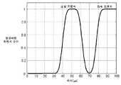
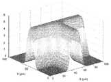
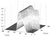
이 문제점을 피하거나 감소시키기 위해, 도 5에 관하여 상술된 시스템(500)은 이중 노출을 피하고 감소시키도록 교차 영역에서 두 개의 특징부들의 플루엔스들을 "혼합(blend)"하기 위해 사용될 수 있다. 예로서, AOD 서브시스템(506)이 그 측벽에서의 플루엔스의 넓은 "경사"를 갖는 하나의 트렌치 특징부를 처리하기 위해, 그리고, 그 종점에서 일치하는 플루엔스 "경사"를 갖는 교차하는 트렌치 특징부를 처리하기 위해 사용되는 경우, 두 개의 플루엔스 분포들은 교차부에서 명목상 평탄한 플루엔스 필드를 생성하도록 조합된다. 따라서, AOD 서브시스템(506)은 깊이-제어된 교차부를 생성하기 위해 사용될 수 있다.To avoid or reduce this problem, the
플루엔스 경사부의 생성은 비임 위치설정 공차들에 기인한 깊이 변화의 최소화 같은 다른 이득들을 제공한다. 교차 영역의 급준한 플루엔스 경사에 의해, 교차 특징부들의 융제 동안 비임 위치의 작은 변화들(예를 들어, 약 1 ㎛ 내지 약 5 ㎛ 정도)은 현저한 깊이 변동을 유발할 수 있다. 플루엔스 내의 점진적 경사를 생성함으로써, 비임 위치설정 에러들은 허용가능한 깊이 변화(예를 들어, 공칭 깊이의 약 10% 내지 약 15% 미만)를 생성한다.The creation of the fluence slope provides other benefits, such as minimization of depth change due to beam positioning tolerances. Due to the steep fluence slope of the crossing area, small changes in beam position during the fluxing of crossing features (eg, on the order of about 1 μm to about 5 μm) can cause significant depth fluctuations. By creating a gradual slope within the fluence, beam positioning errors produce an acceptable depth change (eg, about 10% to less than about 15% of the nominal depth).
교차 특징부들이 진행중에 플루엔스 경사들 및/또는 폭들을 변화시킴으로써 처리될 때 플루엔스 경사의 생성이 구현될 수 있다. 다른 실시예에서, 트렌치 특징부들은 교차부의 외부에서 종결되고(적절한 플루엔스 경사들에 의해), 후속하여, 교차부 체적의 잔여부의 래스터링이 이어진다. 본 실시예는 교차부의 유형에 대한 낮은 감도(예를 들어, 교차하는 트렌치들의 각도, 단일 지점에서 교차하는 다중의 트렌치들, 굴곡된 트렌치들의 교차부들), 인접한 트렌치들 사이의 간격의 바람직하지 못한 변화들을 유발할 수 있는 측부 플루엔스 경사들을 생성하기 위해 사용되는 최소화된 외부 라인 폭 및/또는 교차부의 특성들을 최적화하기 위한 래스터 패턴의 맞춤화를 위한 기능을 포함하는 다수의 장점들을 갖는다. 래스터 패턴의 맞춤화는 다수의 교차하는 트레이스들을 갖는 원형 패드들 같은 교차부에서의 임의적 형상부들을 처리할 때 유용할 수 있다.The generation of the fluence slope can be implemented when the crossing features are processed by changing the fluence slopes and / or widths in progress. In another embodiment, the trench features terminate outside the intersection (by appropriate fluence gradients), followed by rasterization of the remainder of the intersection volume. This embodiment has low sensitivity to the type of intersection (e.g., angle of intersecting trenches, multiple trenches intersecting at a single point, intersections of curved trenches), undesirable spacing of adjacent trenches. It has a number of advantages, including the ability to customize the raster pattern to optimize the characteristics of the cross section and / or the minimized outer line width used to create side fluence slopes that can cause changes. Customization of the raster pattern can be useful when processing arbitrary features at the intersection, such as circular pads with multiple intersecting traces.
교차부 처리의 추가적 세부사항들은 "예시적 교차부 처리 실시예들"이라는 명칭의 장에서 본 명세서에 개시되어 있다.Additional details of crossover processing are disclosed herein in a chapter entitled “Exemplary Crossover Processing Embodiments”.
VI. 갤보 에러 교정VI. Galvo error correction
*반복성 에러의 일 소스(상술된 바와 같은 양호한 깊이 제어에 의해 교차부들의 기계가공 기능을 제한할 수 있는)가 도 5에 도시된 갤보 서브시스템(508)의 위치설정 에러일 수 있다. 이들 에러들은 센서 노이즈 및 추적 에러에 기인할 수 있다. 갤보 서브시스템(508) 내의 각 갤보 거울(533, 535)은 각각의 갤보 서보들(미도시)을 사용하여 거울 이동들을 제어하도록 피드백 센서(미도시)와 연계될 수 있다. 센서 노이즈 효과들은 갤보 서보가 서보의 대역폭 이내의 피드백 센서 노이즈를 추적할 때 발생할 수 있으며, 물리적 비임 이동을 초래한다. 이 에러 여기는 또한 갤보의 폐루프 응답에 의해 증폭될 수 있으며, 이는 주파수 스펙트럼의 일부 부분을 증폭시킨다. 센서 노이즈 효과들은 특정 광학 및 서보 디자인에 따라서 예로서, 약 0.1 ㎛ 평균 자승 근(RMS) 내지 약 5 ㎛ RMS의 비임 에러들을 생성할 수 있다.One source of repeatability error (which can limit the machining function of the intersections by good depth control as described above) may be the positioning error of the
센서 노이즈 효과들은 명령된 비임 궤적에 무관하게 항상 발생할 수 있다. 그러나, 갤보들이 동적 침해적 비임 궤적(큰 가속 또는 고 주파수 명령들을 포함)을 추종하도록 명령될 때, 추적 에러가 발생한다. 명령들을 추적하는 것에 대한 갤보 서보의 불능성은 추적 에러 및 결과적 반복성의 손실을 초래한다. 추적 에러들은 예로서, 선형 서보 응답 성능 및/또는 비선형 갤보 거동(베어링 마찰 또는 자기 히스테리시스 같은)의 결과일 수 있다.Sensor noise effects can always occur regardless of the commanded beam trajectory. However, tracking errors occur when galvos are commanded to follow a dynamic invasive beam trajectory (including large acceleration or high frequency commands). The Galvo Servo's inability to track commands results in tracking errors and resulting loss of repeatability. Tracking errors can be, for example, the result of linear servo response performance and / or nonlinear galvo behavior (such as bearing friction or magnetic hysteresis).
일 실시예에 따라서, 센서 노이즈 에러 및 추적 에러 소스들을 감소시키기 위해, AOD 서브시스템(506)의 편향 기능들이 위치 센서 피드백에 의해 나타내진 바와 같은 갤보 에러들을 교정하기 위해 사용된다. 센서 판독은 센서 노이즈를 포함하며, 이는 이 노이즈에 응답하여 바람직하지 못한 비임 운동의 추가를 감소시키거나 회피하기 위해 정당한 대역폭을 초과하여 필터링 제거될 수 있다. 일 실시예에서, 필터링은 더 높은 주파수들에서 필터링하면서 관련 대역폭 이내의 갤보 위치 센서와 비임 변위("비임 전달 함수" 또는 BTF) 사이의 전달 함수의 이득 및 위상 양자 모두를 실질적으로 일치시킨다. 특정 실시예들에서, BTF는 위치 센서와 갤보 거울 사이의 역학들에 의해 강하게 영향을 받으며, 종종 가볍게 댐핑된 2차 폴에 의해 잘 모델링된다. 신호 필터링 및 데이터 통신에 기인한 시간 지연들 같은 위상 정합에 영향을 주는 다른 인자들은 에러 교정 필터의 디자인에 포함될 수 있다. 도 8은 약 10 kHz를 초과하는 센서 노이즈 필터링과 약 10 kHz 미만의 위상 및 이득 정합의 상충적 요건들 사이의 타협을 제공하는 AOD 에러 교정 필터의 일 예시적 실시예를 도식적으로 예시한다.According to one embodiment, to reduce sensor noise error and tracking error sources, deflection functions of the
또한, 센서 노이즈 배제는 모델링되지 않은 역학들 또는 비선형 거동에 기인하여 일부 실시예들의 감소된 성능의 위험에서, 추정치(예를 들어, Kalman 필터링) 같은 대안들을 통해 달성될 수도 있다.In addition, sensor noise exclusion may be achieved through alternatives, such as estimates (eg, Kalman filtering), at risk of reduced performance in some embodiments due to non-modeled dynamics or nonlinear behavior.
VII. 비임 위치설정 정확도 개선을 감지하기 위한 PSD 거울VII. PSD mirror to detect improved beam positioning accuracy
특정 실시예들에서, AOD 에러 교정은 실제 갤보 거울 위치를 검출하는 외부적 센서들을 사용하여 개선된다. 특정 갤보 기반 비임 위치설정 시스템들에서, 각도 위치 센서는 거울 각도를 감지하기 위해 갤보 내에 내장된다. 센서들은 갤보 샤프트의 먼 단부(거울로부터 이격된)에 위치될 수 있으며, 나머지들은 거울 부근의 샤프트 단부에 위치된다.In certain embodiments, AOD error correction is improved using external sensors that detect the actual galvo mirror position. In certain galvo-based beam positioning systems, an angular position sensor is embedded within the galvo to sense the mirror angle. The sensors can be located at the distal end of the galvo shaft (away from the mirror), and the rest are located at the end of the shaft near the mirror.
각도 위치 센서가 거울로부터 먼 갤보 샤프트의 먼 단부에 위치될 때, 센서는 샤프트 회전을 검출한다. 그러나, 샤프트 각도 편향은 거울이 다양한 편향 각도를 가질 수 있게 한다. 이 센서 배치는 거울 공진에 응답하지 않기 때문에, 서보 대역폭을 증가시키는 기능을 제공하는 소정의 장점들을 갖는다.When the angular position sensor is located at the far end of the galvo shaft far from the mirror, the sensor detects shaft rotation. However, the shaft angle deflection allows the mirror to have various deflection angles. Since this sensor arrangement does not respond to mirror resonance, it has certain advantages that provide the ability to increase servo bandwidth.
각도 위치 센서가 거울 부근의 샤프트 단부에 위치될 때, 센서는 거울에 더 근접한 샤프트의 각도 편향을 검출한다. 이 센서 배치는 진정한 거울 각도를 더욱 정확하게 측정한다. 그러나, 거울 자체가 센서에서 샤프트에 대하여 굴곡될 때 센서는 여전히 에러를 가질 수 있다. 추가로, 이 센서 배치에서, 샤프트 및 거울의 공진이 갤보 주파수 응답에서 발생함으로써(모터 구동부로부터 센서 출력부까지), 갤보 서보 디자인을 복잡하게 하고 그 성능을 제한한다.When the angular position sensor is located at the end of the shaft near the mirror, the sensor detects the angular deflection of the shaft closer to the mirror. This sensor arrangement more accurately measures true mirror angle. However, the sensor may still have errors when the mirror itself is bent against the shaft in the sensor. Additionally, in this sensor arrangement, resonance of the shaft and mirror occurs in the galvo frequency response (from motor drive to sensor output), complicating the galvo servo design and limiting its performance.
추가적으로, 센서 배치 어느 것도 샤프트 각도에 관련되지 않은 거울 모드들을 측정할 수 있다. 하나의 모드는 "플랩핑(flapping)" 거울의 것을 포함하며, 여기서, 거울 평면은 회전 샤프트에 수직인 축을 중심으로 회전한다. 이 모드는 고속 갤보 편향 시스템들의 성능에 대한 제한이 될 수 있다.Additionally, none of the sensor arrangements can measure mirror modes that are not related to the shaft angle. One mode includes that of a “flapping” mirror, where the mirror plane rotates about an axis perpendicular to the rotating shaft. This mode can be a limitation on the performance of high-speed galvo deflection systems.
갤보 회전 센서들의 다른 문제점은 그 노이즈 성능을 포함한다. 위치 센서들의 크기(그리고, 회전 관성)를 최소화하려는 소망 및 갤보들의 작은 패키지 크기에 기인하여, 센서 회로 내에 존재하는 전기적 노이즈는 현저한 유효 각도 노이즈로 변환되고, 이는 갤보 서보 위치설정 성능을 열화시킬 수 있다. 예로서, 이 노이즈는 10 kHz 대역폭 이내의 약 0.1 마이크로라디안(μRad) RMS 내지 약 5 μRad RMS와 동등할 수 있다.Another problem with galvo rotating sensors involves its noise performance. Due to the small package size of galvos and the desire to minimize the size (and rotational inertia) of the position sensors, the electrical noise present in the sensor circuit is converted into significant effective angular noise, which will degrade the galvo servo positioning performance. You can. By way of example, this noise may be equivalent to about 0.1 microradian (μRad) RMS to about 5 μRad RMS within a 10 kHz bandwidth.
일 실시예에서, 샤프트 편향 효과들 없이 거울들의 진정한 각도 위치를 검출하고, 비임 위치 정확도에 영향을 주는 거울 운동의 모든 모드들을 검출하고, 낮은 노이즈 레벨들로 각도 측정을 생성하는 다양한 센서가 선택될 수 있으며, 그래서, 측정은 감지된 에러를 교정하기 위해 갤보 서보 루프 또는 다른 장치들에 의해 사용될 수 있다.In one embodiment, various sensors may be selected that detect true angular position of mirrors without shaft deflection effects, detect all modes of mirror motion affecting beam position accuracy, and generate angle measurements with low noise levels. So, the measurement can be used by a galvo servo loop or other devices to correct the detected error.
특정 실시예들에 따라서, 실제 갤보 거울 위치의 에러들을 교정하기 위해, 도 5에 도시된 갤보 서브시스템(508)은 스캔 렌즈(520)에 관하여 갤보 거울들을 보유하기 위해 피드백을 제공하는 보조 센서(도 5에는 미도시)를 포함한다. 예로서, 도 9는 일 실시예에 따른 갤보 서브시스템(912)의 보조 센서(910)를 포함하는 레이저 처리 시스템(900)의 블록도이다. 본 실시예에서 보조 센서(910)는 위치 감지 다이오드(PSD)를 포함하며, PSD(910)라 본 명세서에서 지칭된다. 또한, 레이저 처리 시스템(900)은 AOD 서브시스템(506), 스캔 렌즈(520), 기준 비임 소스(914) 및 기준 조합기 거울(916)을 포함한다. AOD 서브시스템(506) 및 스캔 렌즈(520)는 작업편(524)의 표면에 집속된 처리 비임(922)을 제공하기 위해 도 5를 참조로 상술되어 있다.In order to correct for errors in the actual galvo mirror position, according to certain embodiments, the
기준 조합기 거울(916)은 갤보 서브시스템(912)에 대한 입력을 위해 AOD 서브시스템(506)으로부터의 처리 비임(920) 및 기준 비임 소스(914)로부터의 기준 비임(918)을 조합한다. 기준 비임 조합기(916)는 안정한 파워 및 포인팅 각도를 갖는 기준 비임을 제공하도록 레이저 비임들을 조합하기 위한 예로서, 다이크로익 거울, 편광 비임 분할 거울 또는 다른 유사 장치를 포함할 수 있다. AOD 서브시스템(506)으로부터의 처리 비임(920)의 사용은 처리 비임의 위치 및 파워가 특정 용례를 위해 충분히 안정적인 경우 PSD 감지 작업 동안 가능할 수 있다(필수적이지는 않음).The
PSD(910)에 추가로, 갤보 서브시스템(912)은 갤보 거울들(924), PSD 픽오프 거울(926) 및 PSD 렌즈(928)를 포함한다. 기준 비임(918)은 갤보 거울들(924)로부터 반사된다(주 처리 비임(920)과 함께). PSD 픽오프 거울(예를 들어, 분할 거울)은 편향된 기준 비임(예를 들어, 갤보 거울들(924)에 의해 편향됨)을 픽 오프하고, 검출을 위해 PSD에 편향된 기준 비임을 안내한다.In addition to
PSD 렌즈(928)(예를 들어, 초점 렌즈)는 검출된 기준 비임의 각도 운동만이 PSD(910) 상의 XY 스팟 편향으로 변환되도록 측정 경로 내에 선택적으로 삽입될 수 있으며, 측방향 비임 운동은 PSD(910)에서의 비임 각도로 변환되고, 따라서, PSD XY 평면에서 측정되지 않는다. 특정 실시예들에서, PSD 렌즈(928)는 PSD 평면에서 스팟 운동을 증폭하기 위해 긴 유효 초점 길이를 갖는 축약적 텔레포토 렌즈를 포함한다. 특정 이런 실시예들에서, PSD 렌즈(928)는 전방 초점이 스캔 렌즈 진입 동공에 위치되도록 위치된다. 특정 실시예들에서, 측방향 비임 운동이 고려되지 않는 경우 PSD 렌즈(928)를 생략할 수 있으며, PSD(910) 상의 비임 운동의 스케일링은 특정 용례에 적합하다.The PSD lens 928 (eg, focus lens) can be selectively inserted into the measurement path such that only the detected angular motion of the reference beam is converted to the XY spot deflection on the
독립적 기준 비임(918) 및 PSD(910)는 PSD 광학 감도와 조합하여 비임 파워가 적절히 낮은 노이즈를 제공하도록 선택될 수 있다. PSD 측정들의 주된 노이즈 소스는 "샷 노이즈"일 수 있거나, 출력 전류의 전하 캐리어들(개별 전자들)의 양자화에 의해 생성된 노이즈일 수 있다. 신호대 잡음비(SNR)는 전류의 자승근에 비례할 수 있다. 출력 전류를 높은 레벨로 상승시킴으로써, SNR이 개선될 수 있으며, 낮은 노이즈 각도 측정이 가능할 수 있다.Independent reference beams 918 and
PSD 감지가 이루어지고 나면, PSD(910)의 출력 대 작업편에서 집속된 처리 비임(922)의 위치가 쉽게 캘리브레이팅될 수 있다. 캘리브레이팅된 PSD(910)가 주어지면, 비임 위치설정은 다수의 방식으로 개선될 수 있다. 예로서, PSD(910)는 갤보 서보들을 위한 위치 피드백 센서로서 사용될 수 있다. 이는 이것이 교차 결합된 시스템을 생성함으로써 피드백 시스템의 역학을 복잡하게 한다는 사실에 의해 복잡해질 수 있다. 추가적으로, 비 회전 거울 모드들("플랩핑" 및 다른 모드들)은 서보 루프에 수용하기에 어려울 수 있다. 역학 추정기들(예를 들어, Kalman 필터들, Luenberger 관찰기들 또는 다른 추정기들)이 역학 모드들을 분리시키고 서보 루프 디자인을 개선시키기 위해 사용될 수 있다.After PSD detection is performed, the output of the
추가적으로 또는 다른 실시예들에서, PSD(910)는 갤보 서브시스템(912) 자체에 의한 제한된 에러 교정을 위해 사용될 수 있다. 예로서, 그 주파수 콘텐츠가 갤보 서보 대역폭 이내인 경우 거울 교차축 모드들은 갤보들에 의해 교정될 수 있다. 추가적으로, 내장된 갤보 센서들(미도시)의 저 주파수 노이즈 에러가 PSD(910)(낮은 주파수에서) 및 내장 센서(높은 주파수들에서)로부터의 피드백을 혼합함으로써 배제될 수 있다.Additionally or in other embodiments,
추가적으로, 또는 다른 실시예들에서, PSD 위치 판독은 비임 경로에 포함된 AOD 같은 별개의 장치에 의해 개루프 에러 교정을 위해 사용될 수 있다. 이는 에러 교정 시스템으로부터 갤보 역학들을 분리시키기 때문에 유용한 동작 모드일 수 있다. 주 처리 비임으로부터 별개의 기준 비임(이는 AOD 서브시스템(506)에 의해 편향될 수 있으며, 따라서, PSD(910)에 의해 감지됨)을 사용하는 것은 AOD 에러 교정이 "개방 루프" 모드에서 동작할 수 있게 하며, AOD 에러 교정은 PSD 비임 위치 출력에 영향을 주지 않는다. 이는 에러 교정 알고리즘을 현저히 단순화할 수 있다. 노이즈 및 거울 편향 모드들 양자 모두는 이런 실시예에서 쉽게 교정될 수 있다.Additionally, or in other embodiments, PSD position reading can be used for open loop error correction by a separate device, such as an AOD included in the beam path. This can be a useful mode of operation because it separates galvo dynamics from the error correction system. Using a separate reference beam from the main processing beam (which can be biased by the
처리 비임(920)이 PSD 기준 비임(918)으로서도 사용되는 경우, 폐쇄 에러 교정 루프를 형성하는 AOD 서브시스템(506)에 의해 유사한 AOD 에러 교정이 여전히 가능하다. 이 경우에, PSD 판독은 의도적 명령들이 PSD(910)에 의해 감지되기 때문에 임의의 의도적 AOD 편향 명령들(디더링, 래스터링 및/또는 고 역학 비임 위치설정)을 제거하는 것으로 분석된다.If the
특정 실시예들에서, 별개의 기준 비임 각도를 감지하는 제1 PSD 센서 및 상술한 실시예들의 이득들을 조합하기 위해 처리 비임 각도를 감지하는 제2 PSD(미도시)를 포함하는 것이 유용할 수 있다. 예로서, 제2 PSD는 진단 측정 및 처리 품질 감시를 위해 사용될 수 있다.In certain embodiments, it may be useful to include a first PSD sensor that senses a separate reference beam angle and a second PSD (not shown) that senses the processing beam angle to combine the gains of the above-described embodiments. . As an example, the second PSD can be used for diagnostic measurement and monitoring of processing quality.
VIII. 처리량 개선들: AOD/갤보 조정 및 제3 프로파일링VIII. Throughput improvements: AOD / galvo adjustment and third profiling
레이저 직접 융제(LDA) 같은 특정 레이저 처리 용례들은 높은 처리량을 달성하도록 높은 처리 비임 속도들(예를 들어, 약 0.2 m/s 및 약 5 m/s 사이의 범위의 속도들)로 특징부들을 융제한다. 고속 처리를 이행하는 한가지 과제는 처리 비임 위치를 제어하기 위해 사용되는 갤보 비임 위치설정 시스템들의 역학 제한들일 수 있다. 짧은 아크 세그먼트들 같은 일부 특징부들의 처리 동안, 비임 위치설정기는 비임 속도 궤적을 변화시키도록 가속한다. 예로서, LDA 용례들은 약 1 ㎛의 바람직한 반복성(갤보 필드 이내)으로 수십 미크론 이하의 정도의 엄격한 전향 반경을 갖는 특징부들의 처리를 필요로할 수 있다. 도 10은 특정 실시예들에 따른 LDA 용례를 위해 처리된 예시적 트렌치 패턴들을 예시하는 개략도이다. 본 명세서에 개시된 실시예들은 트렌치 교차부들(1010), 패드 교차부들(1012), 전이부들(1014)과의 패드 교차부들 및 LDA 처리와 연계된 다른 특징부들의 고속 처리를 제공한다.Certain laser treatment applications, such as laser direct flux (LDA), flux features with high treatment beam speeds (eg, speeds in the range between about 0.2 m / s and about 5 m / s) to achieve high throughput. do. One challenge in implementing high-speed processing may be the mechanical limitations of the galvo beam positioning systems used to control the processing beam position. During processing of some features, such as short arc segments, the beam locator accelerates to change the beam velocity trajectory. By way of example, LDA applications may require treatment of features having a strict forward radius of the order of tens of microns or less with desirable repeatability of about 1 μm (within a galvo field). 10 is a schematic diagram illustrating example trench patterns processed for an LDA application according to certain embodiments. Embodiments disclosed herein provide high-speed processing of
처리 비임 속도가 증가하거나 아크 세그먼트들이 더 짧아질 때, 가속은 비임 위치설정기가 더 높은 대역폭 제어를 사용하는 더 짧은 시간 주기들에 걸쳐 발생한다. 이는 결국 높은 속도들에 도달하는 기능의 한계가 될 수 있다.When the treatment beam speed increases or the arc segments become shorter, acceleration occurs over shorter time periods where the beam positioner uses higher bandwidth control. This can eventually be the limit of the ability to reach high speeds.
다시 도 5를 참조하면, 이러한 제한은 AOD 서브시스템(506) 같은 고속 편향기를 사용하여 비임 궤적 제어의 높은 대역폭 부분을 수행함으로써 회피될 수 있다. 이러한 접근법에서, 갤보 궤적은 갤보 서브시스템(508)의 동적 제약들(예를 들어, 가속 및/또는 대역폭) 내에 남아있으면서 원하는 처리 궤적(526)을 대략 추종하도록 설계될 수 있다. 예로서, 도 11은 일 실시예에 따른 AOD 및 갤보 조화와 연계된 곡선들을 도식적으로 나타낸다. 도 11에 도시된 바와 같이, 갤보 경로(1110)는 원하는 처리 경로(1112)를 정확하게 추종할 수 없어서 비임 궤적 에러를 초래할 수 있다. 비임 궤적 에러는 처리 비임(512)을 추가적으로 편향시키도록 AOD 서브시스템(506)을 사용하여 제거될 수 있다. 예로서, 도 11은 갤보 경로(1110) 및 처리 경로(1112)에 관한 AOD 명령 신호(1114)를 나타낸다. 두 개의 궤적들(갤보 및 처리 비임)이 미리 알려져 있기 때문에, AOD 편향 궤적이 계산될 수 있으며, AOD의 제약들(예를 들어, 범위 및 이 범위에 걸쳐 최대치 정규화된 파워)을 충족시킨다는 것이 확인될 수 있다. 갤보 궤적은 잔류 에러가 AOD의 제약들을 위반하지 않도록 맞춤화될 수 있다. 이는 반복적 프로세스일 수 있으며, 예로서, 갤보 속도는 갤보가 선택된 궤적을 더욱 긴밀하게 추적하고, 따라서, AOD 범위 한계들 내에서 결과적 궤적 에러를 유지할 수 있도록 툴 경로의 특정 부분에서 감소될 수 있다.Referring again to FIG. 5, this limitation can be avoided by performing a high bandwidth portion of beam trajectory control using a high speed deflector such as
다른 실시예는 상술한 바와 같이 AOD 서브시스템(506)을 사용하여 갤보 추적 에러를 "수동적으로" 교정하는 것을 포함한다. 본 실시예에서, 선택된 처리 궤적(526)은 명시적 제약들 없이 계획되며, 갤보 서브시스템(508)은 이 경로를 추종하기를 시도하며, 결과적 추적 에러는 AOD 서브시스템(506)에 의해 교정된다. 이 접근법의 한계들은 갤보 내의 바람직하지 못한 역학들의 여기(거울 공진)를 포함할 수 있으며, AOD 에러 교정의 성능이 특정 용례를 위한 전체적 비임 위치설정 요건들을 충족시키도록 추적 에러를 감소시키기에 충분히 적합하지 않은 위험을 포함할 수 있다.Another embodiment involves "manually" correcting a galvo tracking error using the
특정 실시예들에서, 갤보 에러의 AOD 교정은 잔류 갤보 추적 에러를 제거하기 위해 별개로 생성된 비임 및 갤보 궤적들과 함께 사용될 수 있다. 유효 스팟 크기를 제어하기 위해 비임을 동시에 디더링 및 집속해제하면서 상술한 실시예들 중 임의의 것에 설명된 AOD 동작이 적용될 수 있다.In certain embodiments, AOD correction of the galvo error can be used with separately generated beam and galvo trajectories to eliminate residual galvo tracking error. The AOD operation described in any of the above-described embodiments may be applied while dithering and defocusing the beam simultaneously to control the effective spot size.
처리량에 대한 다른 제한은 특정 패턴의 다양한 부분들을 처리하는데 가용한 레이저 파워일 수 있다. 주어진 재료에 대하여, 처리 투여량(속도로 나누어진 파워)은 융제된 특징부의 단면적의 함수일 수 있다. 시스템이 최대 가용 레이저 파워를 사용하는 경우, 처리 비임 속도는 투여량에 의해 결정될 수 있다(속도=파워/투여량). 높은 처리량을 유지하기 위해 투여량의 변화들에도 불구하고, 최고 가능 속도를 유지하는 것이 바람직할 수 있다. 일부 경우들에서, 이는 투여량의 급속한 변화들에 기인하여 어려울 수 있다. 예로서, 비교적 얇은 트렌치가 대면적 특징부를 형성하기 위해 약 5배(5x)만큼 넓어질 때 높은 속도를 획득하는 것이 어려울 수 있다. 이 경우에, 비임 속도가 이러한 특징부 설정의 길이에 걸쳐 비임 속도가 일정하게 유지되는 경우, 속도는 연장된 영역에서 사용되는 높은 투여량에 의해 제약될 수 있다. 이는 더 얇은 트렌치를 따른 비임 속도를 불필요하게 저속화할 수 있다. 주 비임 위치설정기(갤보들)의 급속한 가속 및 감속은 갤보들의 역학적 한계들에 기인하여 특히 급속한 전이부들을 위해 바람직하지 않을 수 있다.Another limitation on throughput may be the laser power available to process various parts of a particular pattern. For a given material, the treatment dose (power divided by speed) can be a function of the cross-sectional area of the fused feature. When the system uses the maximum available laser power, the treatment beam rate can be determined by the dose (speed = power / dose). Despite changes in dosage to maintain a high throughput, it may be desirable to maintain the highest possible rate. In some cases, this can be difficult due to rapid changes in dosage. As an example, it can be difficult to obtain a high speed when a relatively thin trench is widened by about 5 times (5x) to form a large area feature. In this case, if the beam rate remains constant over the length of this feature set, the rate can be constrained by the high dose used in the extended area. This can unnecessarily slow down the beam speed along the thinner trench. Rapid acceleration and deceleration of the main beam positioner (galvos) may be undesirable, especially for rapid transitions due to the mechanical limitations of the galvos.
일 실시예에 따른 주 비임 위치설정기의 신속한 가속 및 감속을 회피 또는 감소시키기 위해, 가용 AOD 필드는 짧은 세그먼트에 걸쳐 더 낮은 비임 속도를 생성한다. 예로서, 트렌치 특징부가 약 2 m/s의 속도로 처리될 수 있는 것을 가정하면, 100 ㎛의 길이를 갖는 연장된 특징부는 세배(3x) 더 느리게 처리될 수 있다(3x 더 높은 특정 투여량에 기인하여). 2 m/s의 갤보 속도가 변하지 않는 경우, 명목상 비임이 약 50 μs의 넓은 특징부에 걸쳐 통과한다. 그러나, 비임은 약 2/3 = 0.67 m/s의 비임 속도로 특징부를 처리한다(적절한 투여량을 유지하기 위해). 따라서, AOD 편향의 상대적 속도는 약 2 - 0.67 = 1.33 m/s이며, 이는 약 50 μs 동안 적용되어 약 67 ㎛(+/- 약 33 ㎛)의 AOD 편향을 초래한다. 넓은 특징부들에 기인한 전체 섹션의 속도 한계들을 피함으로써, 본 실시예는 약 3x 만큼 국지적 처리 속도를 효과적으로 증가시킨다. 도 12는 예로서, 이런 주기 동안 속도 궤적들을 예시한다. 도 12는 넓은 특징부 또는 높은 투여량을 사용하는 다른 특징부에서 AOD 속도 보상과 연계된 곡선들을 도식적으로 나타낸다. 넓은 특징부의 예상에서, 비임 속도는 국지적으로 속도가 상승되며, AOD 위치가 이동한다. 넓은 특징부에 도달시, 비임 속도가 감소되고, AOD 위치는 저속화를 보상하도록 그 필드를 가로질러 돌려진다(slew). 넓은 특징부의 처리 이후, 비임 속도는 그 속도를 회복하며, AOD 위치는 그 중립 위치로 복귀된다.To avoid or reduce rapid acceleration and deceleration of the main beam positioner according to one embodiment, the available AOD field produces a lower beam speed over a short segment. As an example, assuming that the trench feature can be processed at a rate of about 2 m / s, the extended feature with a length of 100 μm can be processed three times (3x) slower (at a 3x higher specific dose) Due to). If the galvo speed of 2 m / s does not change, the nominal beam passes over a broad feature of about 50 μs. However, the beam treats the feature at a beam speed of about 2/3 = 0.67 m / s (to maintain the proper dose). Thus, the relative speed of the AOD deflection is about 2-0.67 = 1.33 m / s, which is applied for about 50 μs, resulting in an AOD deflection of about 67 μm (+/− about 33 μm). By avoiding the speed limitations of the entire section due to the wide features, this embodiment effectively increases the local processing speed by about 3x. 12 illustrates speed trajectories during this period as an example. 12 schematically shows curves associated with AOD rate compensation in a wide feature or other feature using a high dose. In the expectation of the wide feature, the beam speed is locally increased, and the AOD position shifts. Upon reaching the wide feature, the beam speed is reduced and the AOD position is slewed across the field to compensate for slowing. After processing the wide feature, the beam speed recovers its speed, and the AOD position is returned to its neutral position.
추가로, 또는 다른 실시예에서, 비임의 평균 속도는 일정한 투여량(파워/속도)을 유지하면서 동적으로 변화(변조)될 수 있다. 특정 이런 실시예들에서, AOD 서브시스템(506)은 순시적 갤보 속도의 함수로서 처리 비임 파워를 변조한다. 파워 변조는 더욱 제약된 역학적 요건들(예를 들어, 신속하고 빈번한 융제된 특징부의 배향의 변화들)로 작업편(524)의 섹션들을 처리하기 위해 갤보 거울들(533, 535)을 저속화하거나, 완화된 역학적 요건들을 갖는 섹션들(예를 들어, 배향의 매우 점진적 변화들을 갖는 섹션들 또는 직선 섹션들)에서 갤보 거울들(533, 535)을 속도 상승시키는 기능을 제공한다. 실시간 AOD 파워 제어 없이, 이런 기능들은 가능하지 않으며, 처리량의 손실을 초래한다.Additionally, or in other embodiments, the average rate of the beam can be dynamically changed (modulated) while maintaining a constant dose (power / rate). In certain such embodiments,
평행 라인 세그먼트들(예를 들어, 인접한 트렌치들)을 처리할 때 처리량 개선을 위한 다른 기회가 발생한다. 특정 이런 실시예들에서, AOD 서브시스템(506)은 두 개의 라인들이 동시에 처리되는 것으로 나타나도록 충분히 신속한 속도(예를 들어, 1 μs 정도)로 두 개의 라인들 사이에서 처리 비임(512)을 토글할 수 있다. 동등한 투여량을 필요로하는 동일한 치수의 두 개의 라인들에 대하여, 병렬 처리는 필요한 레이저 파워를 배가시킨다. 파워 제한 시스템에서, 이는 약 50%만큼 감소되는 속도를 필요로 할 수 있음으로써, 처리량 장점들을 제한한다. 그러나, 이는 두 개의 라인들을 위한 설정 이동들을 제거하며, 달리는 전체 속도의 사용을 방지할 수 있는 속도 의존성 역학적 제약들을 감소시킨다. 이런 파워 한계들 없는 시스템들에서, 병렬 라인 처리는 이 섹션을 위한 처리량을 배가시킬 수 있다. 추가로, 양자의 경우들에서, 이런 라인들의 병렬 처리는 라인 임피던스를 제어하기 위해 일부 용례들에서 유익한 라인-라인 간격 제어(이는 AOD 서브시스템(506)의 반복성에 의해 제어됨)를 개선시킨다.Another opportunity to improve throughput occurs when processing parallel line segments (eg, adjacent trenches). In certain such embodiments, the
라인들이 코너를 돌아갈 때, 두 개의 라인들의 경로 길이는 회전 반경, 회전 각도 및 라인 분리에 따라서 서로 다르다. 특정 이런 실시예들에서, 두 개의 라인들의 유효 비임 속도들은 두 개의 라인 세그먼트들의 다양한 경로 길이들을 고려하도록 조절될 수 있다. 이때, 파워(투여량*속도)는 처리가 두 라인들 사이에서 스위칭될 때 AOD 서브시스템(506)에 의해 변조될 수 있다. 라인 세트가 가용 AOD 필드 내에 부합되고 충분한 처리 비임 파워가 적절히 높은 속도를 생성하도록 가용한 한, 동일 접근법은 다수의 라인들로 확장될 수 있다.When the lines turn around the corner, the path lengths of the two lines are different depending on the turning radius, turning angle and line separation. In certain such embodiments, the effective beam speeds of the two lines can be adjusted to account for various path lengths of the two line segments. At this time, the power (dose * speed) can be modulated by the
다수의 라인들을 동시에 처리하는 것은 다수의 라인들이 그 전체적 각각의 경로들에 걸쳐 평행할 때 복잡해질 수 있다. 특정 이런 실시예들에서, 적절한 영역은 병렬로 처리될 수 있으며, 교차 처리를 위해 사용되는 기술에서와 같이 영역들의 단부에 전이 영역이 적용된다(예를 들어, 경사 플루엔스). 그후, 잔여 섹션은 유사하게 전이된 영역을 갖는 종결부에서 처리 및 결합될 수 있다. 이 방식에서, 병렬 처리의 사용은 처리량을 향상시키도록 최대화될 수 있다.Processing multiple lines simultaneously can be complicated when multiple lines are parallel across their respective paths throughout. In certain such embodiments, suitable regions can be processed in parallel, and transition regions are applied at the ends of the regions (eg, sloped fluence) as in the technique used for cross processing. Thereafter, the remaining sections can be processed and combined at the ends with similarly metastasized regions. In this way, the use of parallel processing can be maximized to improve throughput.
도 13은 일 실시예에 따라 결합되는 병렬 처리와 영역을 개략적으로 나타낸다. 도 13은 제1 영역(1308)에서 서로 병렬로 운영되며, 제2 영역(1309)에서 서로 발산되는 복수의 라인들(1306(a), 1306(b), 1306(c), 1306(d))(라인들(1306)이라 총체적으로 지칭됨)을 예시한다. 달리 말하면, 라인들(1306)은 제1 영역(1308)에 평행한 부분들을 가지며, 제2 영역(1309)에 발산하는 부분들을 가진다. 도 13은 라인들(1306)이 평행 부분들로부터 발산 부분들로 변하는 전이 영역(1310)을 예시한다.13 schematically shows the parallel processing and regions being combined according to one embodiment. FIG. 13 is a plurality of lines 1306 (a), 1306 (b), 1306 (c), and 1306 (d) operating in parallel with each other in the
제1 영역(1308)에서 디더링을 사용하여 라인들(1306)을 처리하기 위해, AOD 서브시스템(506)은 레이저 비임이 제1 영역(1308) 내의 상호 처리 궤적을 따른 단일 패스(pass)로 평행 부분들을 처리하도록 라인들(1306)의 평행 부분들 사이에서 전후로 레이저 비임 스팟 위치를 이동시킨다. AOD 서브시스템(506)은 각각의 평행 부분들에 대응하는 다양한 경로 길이들을 초래하는 처리 궤적을 따른 전향부들을 고려하도록 평행 부분들 사이에서 유효 비임 처리 속도들을 조절한다. 또한, AOD 서브시스템(506)은 평행 부분들 각각을 위한 원하는 처리 투여량들을 유지하기 위해 조절된 유효 비임 처리 속도들에 기초한 레이저 비임의 파워를 변조한다. 전이 영역(1310)에 도달시, AOD 서브시스템(506)은 라인들 중 세 개(1306(a), 1306(b) 및 1306(c))의 평행 부분들을 선택적으로 성형하고, 그 처리 궤적을 따른 라인(1306(d))을 처리하기를 지속하면서 전이 영역(1310)에서 세 개의 성형된 라인들(1306(a), 1306(b), 1306(c))의 처리를 종결한다. 성형은 각각의 교차부들에서 원하는 깊이를 유지하면서 추후 시간 지점에서 종결된 라인들(1306(a), 1306(b), 1306(c))이 교차될 수 있게 한다(각각의 발산 부분들). 라인(1306(d))의 발산 부분을 처리한 이후, 라인들(1306(a), 1306(b), 1306(c))의 발산 부분들은 제2 영역(1309)에서 그 각각의 발산하는 처리 궤적들을 따라 순차적으로 처리된다.To process the
도 14는 일 실시예에 따른 제3 프로파일링 서브시스템(1400)을 개략적으로 예시한다. 제3 프로파일링은 제3 위치설정기로서 AOD 서브시스템(506)을 사용하는 것을 지칭한다(예를 들어, XY 스테이지들 및 갤보 서브시스템(508)에 추가로). 예시적 레이저 비임 제3 위치설정기는 미국 특허 제6,706,999호에 개시되어 있으며, 이는 본 발명의 양수인에게 양도되며, 이는 그 전문이 본 명세서에 참조로 통합되어 있다. 본 명세서에 개시된 바와 같이 AOD 서브시스템(506)을 사용하는 제3 프로파일링은 고속으로 비임 경로를 프로파일링할 수 있게 하며(예를 들어, 타이밍 해상도를 제공하도록 약 1 μs의 갱신을 사용하여), AOD 명령들은 불연속 타이밍 경계들 상에서 발령된다. 제3 프로파일링 서브시스템(1400)은 프로파일링 필터(1404), 지연 구성요소(1406) 및 감산기(1408)를 포함한다.14 schematically illustrates a
도 14는 작업편 내로 절삭되는 것이 바람직한 트렌치에 대응하는 예시적 비임 프로파일(1410)을 예시한다. 예시적 비임 프로파일(1410)은 갤보 서브시스템(508)을 사용하여 높은 속도들에서 추적하는 것이 곤란할 수 있는 날카로운 전향부들을 포함한다. 예시적 비임 프로파일(1410)은 프로파일링 필터(1404) 및 지연 구성요소(1406)에 제공된다(명령 비임 위치 신호로서). 프로파일링 필터(1404)는 갤보 서브시스템(508)의 추적을 곤란하게 할 수 있는 높은 주파수 콘텐츠를 필터링 제거하는 저역 통과 필터를 포함한다. 프로파일링 필터(1404)의 출력은 위치 프로파일(1412)에 의해 도시된 바와 같이 갤보 명령(갤보 제어 신호)으로서 사용될 수 있다. 도 14는 위치 프로파일(1412)의 확대 부분(1413)을 예시하며, 이는 갤보 서브시스템(508)에 의해 제공되는 실제 위치(1418)에 관한 명령 신호(1416)를 보여준다. AOD 서브시스템(506)은 명령 위치(1416)와 실제 위치(1418) 사이의 편차를 교정하기 위해 사용된다.14 illustrates an
예시된 실시예에서, 프로파일링 필터(1404)는 유한 임펄스 응답(FIR) 필터를 포함한다. FIR 필터들은 본질적으로 임의의 주파수 범위에서 신호들을 위한 일정한 지연을 갖는다. 그러나, 장인은 본 내용으로부터, 다른 유형의 필터들이 또한 사용될 수 있다는 것을 인지할 수 있을 것이다. 지연 구성요소(1406)는 프로파일링 필터(1404)에 의해 도입된 대략 동일한 양의 지연에 의해 예시적 비임 프로파일(1410)을 지연시킨다. 감산기(1408)는 갤보 명령으로부터 제거되는 고 주파수 콘텐츠를 취득하기 위해 지연 구성요소(1406)의 출력부로부터 프로파일링 필터(1404)의 출력을 차감한다. 감산기(1408)에 의해 출력된 고 주파수 콘텐츠는 그후 AOD 서브시스템(506)을 제어하기 위한 AOD 명령 신호로서 사용될 수 있다. 도 14는 예시적 AOD 위치 명령 프로파일(1414)을 예시한다. 비록, 도시되어 있지 않지만, 대응하는 속도 및 가속도 명령 프로파일들을 계산하기 위해 위치 명령 프로파일(1414) 상에 미분들이 사용될 수 있다.In the illustrated embodiment,
비제한적인 다른 예로서, 도 15a, 도 15b, 도 15c, 도 15d 및 도 15e는 일 실시예에 따른 도 14에 도시된 제3 프로파일링 서브시스템(1400)에 의해 생성 및/또는 사용되는 신호들을 예시한다. 도 15a는 제3 프로파일링 서브시스템(1400)에 대한 예시적 비임 프로파일 입력을 예시한다. 도 15b는 도 15a의 예시적 비임 프로파일에 대응하는 X, Y, XY 비임 속도 궤적들을 도식적으로 예시한다. 도 15c는 도 15a의 예시적 비임 프로파일에 대응하는 X 및 Y 비임 가속 궤적들을 도식적으로 예시한다. 도 15d는 명령 위치, 속도 및 가속 신호들을 포함하는 예시적 갤보 역학들을 예시한다. 도 15e는 명령 편위 및 에러 신호들을 포함하는 예시적 제3 (AOD) 역학을 예시한다.As another non-limiting example, FIGS. 15A, 15B, 15C, 15D, and 15E are signals generated and / or used by the
도 16a, 도 16b 및 도 16c는 특정 실시예들에 따른 예시적 AOD 명령 시퀀스들을 예시한다. 도 16a에서, AOD 명령 시퀀스는약 5 μs 간격들로 AOD를 갱신시키며, 이들은 5 μs 경계들에 정렬된다. 이런 실시예는 저속 처리(예를 들어, 약 200 mm/s에서의 처리)를 위해 충분할 수 있다. 도 16b에서, 고속 AOD 명령 시퀀스는 타이밍 경계들에 정렬되지 않는 약 1 μs 간격들로 AOD를 갱신시킨다. 임의의 타이밍(어떠한 타이밍 경계들에도 정렬되지 않은 갱신들을 갖는)은 일부 실시예들에서 이행하기가 곤란할 수 있다. 예로서, 교차부 처리는 약 2 m/s 내지 약 3 m/s의 고속으로 약 1 μs 해상도로 AOD 전이들이 이루어지는 것을 필요로 할 수 있다. 이런 실시예들을 충족시키기 위해, 일정한 속도로 처리되는 임의적 레이아웃들이 가변적, 서브마이크로초 타이밍 해상도를 사용할 수 있다. 또한, 가변 속도 처리는 증가된 처리량을 위해 좁은 트렌치들에 대해 높은 속도를 제공하고, 플루엔스를 유지하기 위해 넓은 트렌치들에 대해 더 낮은 속도를 제공하며, 래스터 인라인을 위해(예를 들어, 복귀 이동들을 감소 또는 제거하기 위해)래스터링된 영역들에 걸쳐 저속화하고(또는 일시정지) 및/또는 필요시 갤보 추적을 개선시키기 위해, 그리고, 그 경계들 이내로 AOD를 유지하기 위해 저속화하는 것이 바람직할 수 있다.16A, 16B and 16C illustrate exemplary AOD instruction sequences according to certain embodiments. In FIG. 16A, the AOD command sequence updates the AOD at approximately 5 μs intervals, which are aligned at 5 μs boundaries. Such an embodiment may be sufficient for low speed processing (eg, processing at about 200 mm / s). In FIG. 16B, the fast AOD command sequence updates the AOD at approximately 1 μs intervals that are not aligned to the timing boundaries. Any timing (with updates that are not aligned to any timing boundaries) may be difficult to implement in some embodiments. As an example, cross-section processing may require AOD transitions to be made at a high resolution of about 2 m / s to about 3 m / s at a resolution of about 1 μs. To meet these embodiments, arbitrary layouts processed at a constant rate can use variable, submicrosecond timing resolution. In addition, variable speed processing provides high speed for narrow trenches for increased throughput, lower speed for wide trenches to maintain fluence, and for raster inline (eg return) Slowing (or pausing) across rastered areas (to reduce or eliminate movements) and / or to improve galvo tracking as needed, and slowing down to maintain AOD within those boundaries It may be desirable.
일 실시예에서, 타이밍은 위치 기반 AOD 명령들 및 임의적 비임 궤적에 의해 제공된다. 이런 실시예에서, 트리거링은 XY 위치에 기초한다. 따라서, 비선형 비임 위치설정기 궤적을 위해, 트리거는 특징부 위치에 따라 X 축 또는 Y 축에 기초한다. 본 실시예는 작업편이 처리될 때 스트리밍 퍼스트-인-퍼스트-아웃(FIFO) 트리거 데이터, 실시간 위치 명령 데이터(X 및 Y 양자 모두) 및 처리 동안(예를 들어, 전체 필드에 걸쳐 고 해상도) 사용되는 넓은 역학 범위에 기인한 증가된 필드 프로그램형 어레이(FPGA) 데이터 처리 요건들을 가질 수 있다. 본 실시예는 또한 가변적 속도 처리를 제공하지 않는 명령 트리거링을 사용할 수 있다.In one embodiment, timing is provided by location-based AOD instructions and an arbitrary beam trajectory. In this embodiment, triggering is based on the XY position. Thus, for a non-linear beam positioner trajectory, the trigger is based on the X or Y axis depending on the feature location. This embodiment uses streaming first-in-first-out (FIFO) trigger data when the workpiece is processed, real-time position command data (both X and Y) and during processing (e.g., high resolution across the entire field). It may have increased field programmable array (FPGA) data processing requirements due to the wide dynamic range. This embodiment can also use command triggering that does not provide variable speed processing.
다른 실시예에서, 타이밍은 시간 기반 AOD 명령들 및 변형 비임 궤적에 의해 제공된다. 본 실시예는 세그먼트 경계들로 AOD 명령 전이들을 제한할 수 있으며, 세그먼트들은 필요에 따라 AOD 명령들을 포함하도록 세분될 수 있다. 본 실시예는 비임 속도로부터 처리 형상을 커플링 해제하는 위치 (비 시간) 경계들에 세그먼트들을 정렬시킨다. 또한, 본 실시예는 경계들이 규칙적 시간 간격들에 타격되도록 세그먼트 속도들을 조절하며, 이는 유연성, 가변적 처리 속도, 제3 비임 위치설정기로 쉽게 구현되는 속도 변동 및 속도 변동을 제약하기 위한 AOD 전이 간격에 대한 적절한 규제들을 제공한다. 이 접근법은 예로서, 펄스형 레이저 시스템들에서 바람직할 수 있으며, 이는 불연속적인 예측가능한 시간 경계들에 대한 레이저 펄싱 제어를 필요로 할 수 있다.In another embodiment, timing is provided by time-based AOD instructions and a modified beam trajectory. This embodiment can limit AOD instruction transitions to segment boundaries, and segments can be subdivided to include AOD instructions as needed. This embodiment aligns the segments at the location (non-time) boundaries that uncouple the treatment shape from the beam velocity. In addition, the present embodiment adjusts segment speeds such that the boundaries strike at regular time intervals, which is flexible, variable processing speed, speed fluctuations easily implemented with a third beam positioner and AOD transition intervals to constrain the speed fluctuations. Providing appropriate regulations. This approach may be desirable, for example, in pulsed laser systems, which may require laser pulsing control over discontinuous predictable time boundaries.
도 16c에서, AOD 갱신들은 1 μs 간격들로 이루어지며, 분리된 결정론적 1 μs 경계들에 정렬된다. 그러나, 특징부 위치들은 툴경로 내에 임의적으로 위치될 수 있다. 임의적으로 위치된 특징부들을 시간적으로 정렬하기 위해, 특징부들 사이의 속도는 사전결정된다. 따라서, 특정 이런 실시예들에서, 특징부들 사이에서 세그먼트로부터 세그먼트까지 속도 변조가 사용된다. 도 17a 및 도 17b는 특정 실시예들에 따른 속도 변조의 예들을 도식적으로 예시한다. 도 17a에서, 속도 변조는 최적 처리 속도에 대응하는 위치 증분들에 기초한 타이밍을 사용한다. 도 17b에서, 속도 변조는 타이밍을 분리된 시간 증분들(동일 위치 증분들)에 정렬시킴으로써 속도를 조절한다. 특정 실시예들에서, 명목상 Dseg/Vnom과 같은 세그먼트 경계들 사이의 시간 델타(Δ)는(Dseg = 세그먼트 길이, Vnom = 최대 처리 속도) 다음 불연속 타이밍 경계까지 라운딩된다. 속도 변조 동안, 투여량은 일정하게 유지될 수 있다(예로서, 속도 변화들로서 파워를 변화시킴으로써). 최소 위치 증분(ΔPmin) 및 최대 타이밍 증분(ΔT)은 Vnom*ΔT/ΔPmin으로 처리 속도의 상대적 강하를 구속하도록 선택될 수 있으며, 여기서, Vnom은 공칭 속도이다. 예로서, ΔT는 1 μs가 되도록 선택될 수 있으며, ΔPmin은 3 m/s로 15% 속도 변화를 제공하도록 20 ㎛이 되도록 선택될 수 있다. 속도 변동이 단지 짧은 시간 기간 동안 발생하기 때문에, 이는 처리량에 대한 미소한 영향을 갖거나 전혀 영향을 갖지 않을 수 있다.In FIG. 16C, AOD updates are made at 1 μs intervals, aligned to separate deterministic 1 μs boundaries. However, feature locations can be arbitrarily located within the toolpath. To temporally align randomly located features, the speed between features is predetermined. Thus, in certain such embodiments, speed modulation is used from segment to segment between features. 17A and 17B schematically illustrate examples of speed modulation according to certain embodiments. In Fig. 17A, speed modulation uses timing based on position increments corresponding to the optimal processing speed. In FIG. 17B, speed modulation adjusts speed by aligning the timing to separate time increments (same position increments). In certain embodiments, the time delta (Δ) between segment boundaries, such as nominally Dseg / Vnom (Dseg = segment length, Vnom = maximum processing speed) is rounded to the next discontinuous timing boundary. During rate modulation, the dosage may remain constant (eg, by varying power as rate changes). The minimum position increment (ΔPmin) and the maximum timing increment (ΔT) can be selected to constrain the relative drop in processing speed to Vnom * ΔT / ΔPmin, where Vnom is the nominal speed. As an example, ΔT can be selected to be 1 μs, and ΔPmin can be selected to be 20 μm to provide a 15% velocity change at 3 m / s. Since the rate fluctuation only occurs over a short period of time, it may have little or no effect on throughput.
제3 프로파일링은 불연속 AOD 갱신 주기 및 AOD 속도 항으로부터 초래되는 위치설정 에러를 생성할 수 있다. 예로서, 도 18은 일 실시예에 따른 결과적 AOD 위치 프로파일(1814) 및 위치 명령 신호(1812)에 관한 위치설정 에러(1810)를 도식적으로 예시한다. 도 18에 도시된 바와 같이, AOD는 예로서, 기계적 거울과 동일한 방식으로 명령 갱신들 사이에서 돌려지지 않는다. 따라서, 예로서, 3 m/s의 속도로 1 μs 갱신 주기는 약 +/- 1.5 ㎛의 위치설정 에러를 생성할 수 있다. 갱신 주기는 필요시 이 에러를 제한하기 위해 감소될 수 있다. RF 파형의 처핑은 특정 실시예들에서 위치설정 에러들을 감소시킬 수 있다. 도 15e는 예시적 위치 에러를 도식적으로 예시한다.The third profiling can generate a positioning error resulting from the discontinuous AOD update period and the AOD speed term. As an example, FIG. 18 schematically illustrates a
IX. 비임 위치설정 안정화IX. Stabilization of beam positioning
양호한 정확도 및/또는 반복성을 제공하는 특정 레이저 처리 용례들에서, 각도 또는 병진 비임 지터의 기여도는 에러 예산의 현저한 부분이 될 수 있다. 지터는 레이저 소스에 고유한 비임 운동에 기인할 수 있거나 비임 경로의 공기 난류 및/또는 광학장치 트레인 내의 기계적 진동들에 기인할 수 있다(비임 경로 내의 공기 온도 편차들에 의해 심화되는). 레이저 스캐닝 시스템에서, 각도 에러는 스캔 렌즈 초점 길이에 의해 스케일링될 때 작업편에서의 위치 에러들에 직접적으로 기여한다. 비임 병진 에러들은 작업편에서 (보상되지 않은) 비임 각도를 생성함으로써, 작업편 에러들에 간접적으로 기여하며, 작업편 표면의 임의의 Z 높이 변동에 의해 스케일링된 이러한 각도는 작업편 상의 XY 비임 위치설정 에러들을 생성한다.In certain laser processing applications that provide good accuracy and / or repeatability, the contribution of angular or translational beam jitter can be a significant part of the error budget. The jitter can be due to beam motion inherent in the laser source or due to air turbulence in the beam path and / or mechanical vibrations in the optics train (intensified by air temperature variations in the beam path). In a laser scanning system, the angular error directly contributes to position errors in the work piece when scaled by the scan lens focal length. Beam translation errors contribute indirectly to the work piece errors by generating a (uncompensated) beam angle in the work piece, and this angle scaled by any Z height variation on the work piece surface is the XY beam position on the work piece. Generate configuration errors.
도 5에 도시된 시스템(500) 같은 AOD 편향 기능들을 구비한 시스템은 미소한 추가적 작동 비용으로 또는 어떠한 추가적 작동 비용도 없이 비임 지터를 교정할 수 있다. 광학 경로(예를 들어, 스캔 렌즈(520) 부근)를 따라 센서(미도시)를 배치함으로써, 피드백 제어는 스캔 렌즈(520) 내로 정확하게 위치설정된 비임을 유지하도록 AOD 편향을 명령할 수 있으며, 이는 비임 위치 정확성 및 반복성을 개선시킬 수 있다. 다수의 비임 지터 소스들의 주파수 콘텐츠는 비교적 낮을 수 있으며(예를 들어, 공기 난류에 대하여 약 10 Hz 미만, 그리고, 기계적 진동에 대하여 약 500 Hz 미만), 따라서, AOD 서브시스템(506)에 의해 쉽게 교정될 수 있다. 이러한 접근법의 제한 인자는 비임 각도 및 병진을 검출하기 위해 사용되는 센서의 노이즈 콘텐츠일 수 있다.A system with AOD deflection functions, such as
AOD의 의도적 편향(선택된 작업편 궤적을 생성하도록 명령된)은 측정들을 수행할 때 고려될 수 있다. 예로서, 중계 광학장치가 AOD 편향된 비임을 스캔 렌즈(520)로 전송하기 위해 사용되지 않는 광학 트레인에서, AOD 서브시스템(506)으로부터 스캔 렌즈(520)까지 비임 경로 길이에 의해 스케일링될 때 AOD의 편향 각도는 스캔 렌즈(520)에 병진 오프셋을 생성한다. 간단한 캘리브레이션은 지터 교정 이전에 측정으로부터 이것이 제거될 수 있게 한다. 캘리브레이션은 필요시 AOD 서브시스템(506)으로부터 스캔 렌즈(520)까지의 초점 길이의 함수로서 수행될 수 있다. 그러나, 일반적으로, 처리 비임이 센서 상에 집속되는 경우, 측방향 비임 운동이 센서에서 스팟 위치에 영향을 주지 않기 때문에 어떠한 이런 보상도 필요하지 않을 수 있다.The intentional deflection of the AOD (commanded to generate the selected workpiece trajectory) can be taken into account when performing measurements. As an example, in an optical train where relay optics are not used to transmit the AOD biased beam to scan
또한, 지터 교정은 고 파워 AOD 장치들을 발생시킬 수 있는 AOD 가열에 기인한 비임의 열적 드리프트 같은 AOD 동작으로부터의 바람직하지 못한 부차적 영향들을 교정할 수 있다는 것을 주의하여야 한다.It should also be noted that jitter calibration can correct undesirable side effects from AOD operation, such as thermal drift of the beam due to AOD heating, which can result in high power AOD devices.
X. 처리 개선들: 듀티 사이클X. Treatment Improvements: Duty Cycle
일부 실시예들에서, AOD 서브시스템(506)은 레이저/재료 상호작용 처리 개선들을 가능하게 한다. 일 예에서, 유전체 재료 내로 절삭된 트렌치의 단면적은 작업편에 인가되는 "투여량"(비임 속도에 의해 나뉘어진 처리 비임 파워)에 대해 민감하다. 일부 용례들에서 최상의 또는 개선된 성능을 위하여, 인가된 투여량은 용융 또는 차링 같은 열 영향 영역(HAZ) 효과들을 피하기 위해 재료의 융제 임계치보다 매우 높게 유지될 수 있다. 비임 위치설정기 역학들 또는 레이저 파워에 의해 부여되는 제약들에 기인한 일부 상황들에서 사용될 수 있는 낮은 속도들에서, 적용된 투여량은 바람직하지 못한 HAZ 효과들을 생성하기 시작할 수 있다. 따라서, 일 실시예에 따른 HAZ 효과들을 회피 또는 감소시키기 위해, AOD 서브시스템(506)은 특정 작동 조건을 위해 사용되는 것의 레벨로 평균 파워를 감소시키면서 높은 피크 파워가 유지되도록 처리 비임(512)의 파워 듀티 사이클을 변조시킨다. 예로서, 약 100 mm/s로 처리 비임(512)을 이동시킬 때, 약 10%의 듀티 사이클(약 1 μs 온, 9 μs 오프)로 비임을 변조시키는 것은 감쇄된 100% 듀티 사이클 비임에 대하여 약 10 배(10x) 만큼 피크 파워를 증가시키면서 약 1 ㎛의 수용가능하게 작은 "바이트 크기"(펄스 간격 당 증분 처리 길이)를 생성한다. 상술한 지터 교정에서와 같이, 이 기능은 미소한 추가적 비용으로 또는 어떠한 추가적 비용도 없이 추가될 수 있다.In some embodiments,
XI. 처리 개선들: 플룸 회피XI. Treatment improvements: plume avoidance
AOD 작업은 또한 작업편 상의 또는 작업편 내의 타겟 재료의 융제 동안 플룸 효과들을 감소시키거나 회피하는 기능을 제공할 수 있다. 플라즈마, 가스 또는 미립자 파편으로서 배출될 수 있는 작업편으로부터 융제된 재료는 예로서, 파전두 왜곡, 파워 감쇄 및/또는 포인팅 효과들을 통한 처리 비임 스팟의 품질에 영향을 줄 수 있다. 일 실시예에 따른 플룸 효과들을 완화시키기 위해, 처리 스팟의 위치는 처리 동안 각 스팟이 이전 스팟의 플룸 효과들에 의해 영향을 받지 않도록 스위칭된다. 처리 스팟 위치가 가용 AOD 필드 거리(Daod)에 걸쳐 N 위치들(선택된 처리 궤적을 따라 모든 스팟들이 배치됨) 사이에서 스위칭될 수 있는 경우, 처리 속도(V)에서의 운영시, 순방향 처리 스팟의 플룸이 다음 스팟에 영향을 주기 이전에 Daod/V/N 초들 동안 소산시킨다. 예로서, 위치 N=5, Daod=50 ㎛, V = 2 m/s일 때, 순방향 처리 스팟의 플룸은 다음 스팟에 영향을 주기 이전에 소산되도록 약 5 μs를 가질 수 있다. 처리 궤적이 굴곡된 세그먼트들을 포함할 때, 분산된 스팟들의 위치들은 선택된 궤적을 유지하도록 조절될 수 있다.AOD work can also provide the ability to reduce or avoid plume effects during the fluxing of the target material on or within the work piece. Materials fused from a workpiece that can be discharged as plasma, gas, or particulate debris can affect the quality of the treatment beam spot through, for example, wave front distortion, power attenuation, and / or pointing effects. To mitigate plume effects according to one embodiment, the location of the treatment spot is switched so that each spot during processing is not affected by the plume effects of the previous spot. If the processing spot position can be switched between N positions (all spots are placed along the selected processing trajectory) over the available AOD field distance (Daod), when operating at processing speed V, the plume of the forward processing spot Dissipate for Daod / V / N seconds before affecting this next spot. As an example, when position N = 5, Daod = 50 μm, V = 2 m / s, the plume of the forward treatment spot can have about 5 μs to dissipate before affecting the next spot. When the processing trajectory includes curved segments, the positions of the distributed spots can be adjusted to maintain the selected trajectory.
XII. 관통 렌즈 관찰XII. Through-lens observation
레이저 처리 기계들에서, 처리 비임들은 작업편 특징부들에 정렬된다. 정렬은 정렬 카메라로 작업편 정렬 기점(예를 들어, 정렬 타겟)을 식별하고, 그후, 캘리브레이션을 통해 처리 비임 위치로 카메라 시계를 맵핑함으로써 수행될 수 있다. 속도 및 효율은 이것이 2 단계 프로세스(레이저-카메라 캘리브레이션 에러 및 카메라 기점 식별 에러를 수반함)를 사용하기 때문에, 그리고, 카메라 및 스캔 렌즈가 서로 분리되기 때문에 감소될 수 있으며, 이는 위치설정 스테이지 반복성 및 정확도에 기인한 다른 불확실성을 추가한다.In laser processing machines, the treatment beams are aligned to the workpiece features. Alignment can be performed by identifying the workpiece alignment origin (eg, alignment target) with the alignment camera, and then mapping the camera field of view to the processing beam location via calibration. Speed and efficiency can be reduced because it uses a two-step process (which involves laser-camera calibration errors and camera origin identification errors), and because the camera and scan lens are separate from each other, this can help with positioning stage repeatability and Add other uncertainties due to accuracy.
특정 실시예들에서, 하나의 이미지 내에서 처리 비임 및 작업편 양자 모두의 모습을 포착하기 위해 렌즈 관통 관찰을 사용하는 것이 더욱 바람직하며, 이는 비임과 기점 타겟 사이의 상대적 위치의 측정을 가능하게 한다. 이는 두 개의 파장들(처리 파장 및 관찰 파장)에서의 동작을 위해 도 5에 도시된 스캔 렌즈(520)를 설계함으로써 달성될 수 있다. 처리 파장 및 관찰 파장 양자 모두를 달성하기 위해 스캔 렌즈 디자인에 때때로 절충이 이루어질 수 있다. 일 실시예는 기점의 이미징시 처리 비임 파장으로 작업편(524)을 조명함으로써 이 절충을 극복한다.In certain embodiments, it is more preferable to use through-lens observation to capture the appearance of both the processing beam and the work piece within one image, which enables measurement of the relative position between the beam and the fiducial target. . This can be achieved by designing the
예로서, 도 19는 일 실시예에 따른 래스터 조명을 위해 AOD 서브시스템(506)을 사용한 관통 렌즈 관찰을 위한 시스템(1900)의 블록도이다. 또한, 시스템(1900)은 카메라(1910), 이미징 렌즈(1912), 거울(1914), 부분 반사기(1916) 및 스캔 렌즈(520)를 포함한다. 도 5에 관하여 상술된 바와 같이, AOD 서브시스템(506)은 스캔 렌즈(520)에 제공된 처리 비임(512)을 편향시키기 위해 AOD들(530, 532)을 포함하며, 이는 집속된 레이저 비임(525)을 작업편(524)에 제공한다. 이는 처리 비임(512)과 동일한 파장을 갖는 조명 소스를 발견하는 것이 어려울 수 있으며, 다양한 파장(수 나노미터 이내에서도)을 사용하여 검사 해상도를 열화시킬 수 있다.As an example, FIG. 19 is a block diagram of a
대신, 처리 비임(512)의 일부는 분할될 수 있고, 작업편(524)을 조명하기 위해 사용될 수 있다. 이는 비임 분할기들 및 확산기들 또는 다른 집속해제 구성요소들로 수행될 수 있으며, 이들은 추가적 광학 구성요소들, 정렬 및 복잡성을 추가할 수 있다. 따라서, 도 19에 도시된 실시예에서, AOD 서브시스템(506)은 균일한 플루엔스로 작업편(524) 상의 영역을 충전하는 래스터 패턴을 사용하여 작업편(524)을 조명하기 위해 사용되며, 래스터 패턴은 작업편(524)에 대한 처리 비임의 정렬을 위한 기준으로서 사용하기 위해 더 높은 강도의 하나의 기준 스팟을 포함한다. 부분적 반사기(1916)는 작업편(524)으로부터 반사된 광을 픽 오프하며, 거울(1914)은 카메라(1910)에 이미지를 집속시키기 위해 이미징 렌즈(1912)를 통해 반사된 광을 재안내한다. 스캔 렌즈(520) 내로 작업편(524)으로부터 반사된 광을 픽 오프 및 재 이미징을 위한 광학 경로를 추가하는 것은 작업편(524) 및 기준 스팟을 카메라(1910)가 이미징할 수 있게 하며, 기점에 대한 비임의 상대적 정렬을 결정한다.Instead, a portion of the
도 19에 도시된 실시예는 스팟 초점을 유지(정렬 카메라 내의 스팟 크기를 최소화하는)하도록 정확한 스캔 렌즈(Z) 높이 조절을 결정하는 기능을 제공할 수 있다. 세 개 내지 다섯 개의 별개의 렌즈(Z) 높이들에서 재 이미징된 스팟 크기를 기록하는 것은 예상 스팟 크기 성장 대 Z 높이에 대한 곡선 정합 이후 최적의 스팟 위치를 유도하기에 충분한 정보를 제공할 수 있다.The embodiment shown in FIG. 19 may provide a function of determining the correct scan lens Z height adjustment to maintain spot focus (minimizing spot size in the alignment camera). Recording the re-imaged spot size at three to five distinct lens (Z) heights can provide enough information to derive the optimal spot position after curve matching for expected spot size growth versus Z height. .
정렬 기술은 매우 양호한 비임-대-기점 정렬 정확도(예를 들어, 스팟 크기의 약 10% 미만)를 제공할 수 있다. 이는 작업편 상의 XY 위치가 처리 및 정렬을 위해 동일할 수 있기 때문에, 작업편 상에 두 개의 별개의 스캔 필드 영역들을 신속히 정렬시키는 기능을 제공할 수 있다. 하나의 스캔 필드의 스팟을 인접한 스캔 필드의 처리된 특징부에 정렬시킴으로써, 두 개의 처리 필드들은 높은 정확도로 또한 함께 결합되어 별개로 처리될 수 있다.The alignment technique can provide very good beam-to-base alignment accuracy (eg, less than about 10% of the spot size). This can provide the ability to quickly align two separate scan field areas on the workpiece, since the XY position on the workpiece can be the same for processing and alignment. By aligning the spots of one scan field to the processed features of adjacent scan fields, the two processing fields can also be processed separately with high accuracy and also joined together.
관통 렌즈의 추가적 특징은 처리 대상 부분의 표면에 걸쳐 비임 위치설정 에러들을 맵핑하는 기능이다. 이런 큰 필드에 걸쳐 일부를 처리하는 한가지 과제는 비임이 비 텔레센트릭형이면서(예를 들어, 작업편에서의 비임 각도가 0이 아니거나 법선을 벗어날 수 있음) 필드에 걸쳐 변한다는 것이다. 임의의 Z 높이 변화로 승산된 이 각도는 XY 위치설정 에러를 생성한다. 큰 필드 스캔 렌즈를 위한 텔레센트릭 각도는 약 15도까지일 수 있다. 작업편 표면 변동은 약 +/- 100 ㎛일 수 있다. 따라서, 텔레센트릭 각도들 및 작업편 표면 변동의 조합은 약 +/- 26 ㎛까지의 XY 에러들을 생성할 수 있다(예를 들어, 약 10 ㎛과 약 20 ㎛ 사이의 범위의 에러 예산에 대하여). 필드 내의 다수의 지점들에서 이들 위치 오프셋들을 기록하기 위해 관통 렌즈 관찰을 사용함으로써(처리 필드에 걸쳐 이 부분의 Z 영역을 정확하게 맵핑하기에 충분한 샘플들), 텔레센트릭 에러들이 제거될 수 있다. 작업편 상의 기준 기점들의 세트는 기점들에 대한 처리 스팟의 위치가 정확하게 측정(수 미크론 이내로)될 수 있도록 사용될 수 있다. 관통 렌즈 설정의 스팟 위치의 절대적 측정이 곤란할 수 있다. 그러나, 스팟 위치 측정들은 부분 처리 동안 실시간으로 또는 정렬 동안 수행될 수 있다.An additional feature of the through lens is the ability to map beam positioning errors across the surface of the portion to be treated. One challenge in handling some over these large fields is that the beams are non-telecentric, for example, the beam angle on the workpiece may vary across the field, or may not be zero. This angle multiplied by any Z height change produces an XY positioning error. The telecentric angle for a large field scan lens can be up to about 15 degrees. The workpiece surface variation can be about +/- 100 μm. Thus, a combination of telecentric angles and workpiece surface variation can produce XY errors up to about +/- 26 μm (eg, for an error budget in the range between about 10 μm and about 20 μm). ). By using a through-lens observation to record these position offsets at multiple points in the field (samples sufficient to accurately map the Z region of this portion across the processing field), telecentric errors can be eliminated. The set of reference fiducials on the work piece can be used so that the position of the treatment spot relative to the fiducials can be accurately measured (within a few microns). Absolute measurement of the spot position of the through lens setting may be difficult. However, spot position measurements can be performed in real time during partial processing or during alignment.
일 실시예에서, 방법은 작업편 특징부들에 처리 레이저 비임을 정렬하는 단계를 포함한다. 처리 레이저 비임은 작업편 특징부들을 처리하기 위한 사전결정된 파장을 포함한다. 이 방법은 작업편에 스캔 렌즈를 통한 전파 경로를 따라 처리 레이저 비임을 전파하는 단계를 포함한다. 이 방법은 사전결정된 파장의 조작된 처리 레이저 비임으로 정렬 타겟을 포함하는 작업편의 선택된 영역을 스캔 렌즈를 통해 조명하도록 처리 레이저 비임을 조작하는 단계를 더 포함하며, 선택된 영역은 스캔 렌즈를 통해 제공되는 처리 레이저 비임의 기준 레이저 비임 스팟보다 크다. 이 방법은 작업편의 선택된 영역을 이미징하기 위한 카메라에 스캔 렌즈를 통해 조작된 처리 레이저 비임의 반사의 적어도 일부를 다시 안내하는 단계와, 카메라에 의해 포착된 선택된 영역의 이미지에 기초하여, 정렬 타겟에 대한 기준 레이저 비임 스팟의 위치를 결정하는 단계를 더 포함한다.In one embodiment, the method includes aligning the processing laser beam to the workpiece features. The processing laser beam includes a predetermined wavelength for processing workpiece features. The method includes propagating the processing laser beam along a propagation path through the scan lens to the workpiece. The method further comprises manipulating the processing laser beam to illuminate through the scanning lens a selected area of the workpiece comprising the alignment target with a manipulated processing laser beam of a predetermined wavelength, the selected area being provided through the scanning lens The treatment laser beam is larger than the reference laser beam spot. The method further guides at least a portion of the reflection of the processed laser beam manipulated through the scan lens to the camera for imaging the selected area of the workpiece, and based on the image of the selected area captured by the camera, the alignment target And determining the location of the reference laser beam spot for.
일 실시예에서, 레이저 처리 시스템은 작업편 특징부들에 처리 레이저 비임을 정렬시키기 위해 제공된다. 처리 레이저 비임은 작업편 특징부들을 처리하기 위한 사전결정된 파장을 포함한다. 시스템은 처리 레이저 비임을 제공하기 위한 레이저 소스와, 작업편 상에 또는 그 내에 레이저 비임 스팟에서 처리 레이저 비임을 집속시키기 위한 스캔 렌즈와, AOD 서브시스템을 포함한다. AOD 서브시스템은 균일한 플루엔스로 스캔 렌즈를 통해 작업편의 선택된 영역을 조명하는 레이저 비임 스팟의 래스터 패턴을 생성하며, 선택된 영역은 정렬 타겟을 포함한다. AOD 서브시스템은 선택된 영역 내의 기준 레이저 비임 스팟을 스캔 렌즈를 통해 추가로 제공하며, 기준 레이저 비임 스팟은 레이저 비임 스팟들의 래스터 패턴의 것보다 높은 강도이다. 또한, 이 시스템은 스캔 렌즈를 통해 선택된 영역으로부터의 처리 레이저 비임의 반사의 적어도 일부를 다시 안내하기 위한 광학 구성요소들과, 작업편의 선택된 영역을 이미징하기 위한 카메라를 포함한다. 선택된 영역의 이미지는 정렬 타겟에 대한 기준 레이저 비임 스팟의 위치를 결정하기 위해 사용된다.In one embodiment, a laser processing system is provided to align the processing laser beam to workpiece features. The processing laser beam includes a predetermined wavelength for processing workpiece features. The system includes a laser source for providing a processed laser beam, a scan lens for focusing the processed laser beam at a laser beam spot on or within the workpiece, and an AOD subsystem. The AOD subsystem creates a raster pattern of the laser beam spot that illuminates a selected area of the workpiece through a scan lens with a uniform fluence, and the selected area includes an alignment target. The AOD subsystem further provides a reference laser beam spot in the selected area through a scan lens, the reference laser beam spot being of higher intensity than that of the raster pattern of the laser beam spots. The system also includes optical components to guide back at least a portion of the reflection of the processing laser beam from the selected area through the scan lens, and a camera to image the selected area of the workpiece. The image of the selected area is used to determine the position of the reference laser beam spot relative to the alignment target.
특정 실시예들에서, 광학 구성요소들은 스캔 렌즈를 통해 선택된 영역으로부터 처리 레이저 비임의 반사를 수신하기 위한 부분 반사기와, 부분 반사기로부터 처리 레이저 비임의 반사의 적어도 일부를 수신하고 카메라의 개구 상으로 이 반사의 적어도 일부를 집속시키기 위한 이미징 렌즈를 포함한다.In certain embodiments, the optical components receive a partial reflector for receiving a reflection of the processing laser beam from a selected area through a scan lens, and receive at least a portion of the reflection of the processing laser beam from the partial reflector and move it over the aperture of the camera. And an imaging lens for focusing at least a portion of the reflection.
특정 실시예들에서, 시스템은 정렬 타겟에 대한 기준 레이저 비임 스팟의 결정된 위치에 기초한 위치설정 에러를 계산하기 위한 제어기를 더 포함한다. 계산된 위치설정 에러에 기초하여, 제어기는 AOD 서브시스템에게 선택된 작업편 특징부에 대해 처리 레이저 비임 스팟 위치를 위치설정하도록 명령한다. 처리 레이저 비임은 선택된 작업편 특징부를 처리하기 위해 처리 레이저 비임 스팟 위치에서 사전결정된 파장의 처리 레이저 비임을 집속하도록 스캔 렌즈를 통해 전파 경로를 따라 전파한다.In certain embodiments, the system further includes a controller to calculate a positioning error based on the determined position of the reference laser beam spot relative to the alignment target. Based on the calculated positioning error, the controller instructs the AOD subsystem to position the processing laser beam spot position for the selected workpiece feature. The processing laser beam propagates along the propagation path through the scan lens to focus the processing laser beam of a predetermined wavelength at the processing laser beam spot location to process the selected workpiece feature.
XIII. 예시적 AOD 제어 실시예들XIII. Exemplary AOD control embodiments
(a) 서론(a) Introduction
본 절은 처리 동안 AOD 편향 명령들을 결정하는 예시적 수학식들을 포함하는 일 실시예에 따른 AOD 제어 아키텍쳐를 사용한 LDA 처리를 설명한다.This section describes LDA processing using an AOD control architecture according to one embodiment including example equations for determining AOD bias commands during processing.
AOD는 적어도 두 개의 기능들을 제공한다: (1) 처리 비임 치수를 확장시키기 위한 비임 위치 디더링 및 (2) 융제된 특징부들 상의 경사 제어를 가능하게 하기 위한 진폭 변조. 경사 제어는 특징부 교차부들에서 허용가능한 깊이 변동을 획득하는 양태이다.AOD provides at least two functions: (1) beam position dithering to expand the processing beam dimension and (2) amplitude modulation to enable tilt control on the fused features. Tilt control is an aspect of obtaining acceptable depth variation at feature intersections.
AOD 주파수 및 진폭 변조 명령들은 본 실시예에서 FPGA를 통해 갱신된다. 예로서, 도 22는 일 실시예에 따른 FPGA(2200)에서 구현된 AOD 제어 데이터 유동을 나타내는 블록도이다. 공칭 갱신 주기는 약 260 ns이다. 기본적 디더 테이블(2210)은 용례당 기반으로 FPGA(2200) 내에 로딩될 수 있다. 이 디더 패턴은 처리 동안 동적으로 두 개의 AOD 축들 사이에서 스케일링 및 분할된다. 추가적으로, 진폭 변조 명령은 레이저 파워를 동적으로 제어한다.AOD frequency and amplitude modulation commands are updated through the FPGA in this embodiment. As an example, FIG. 22 is a block diagram illustrating AOD control data flow implemented in the
숙련자는 본 아키텍쳐가 예로서, 다양한 디더 파형들의 세트들, 갤보 에러 교정 및/또는 프로파일링 보조를 포함하도록 확장될 수 있다는 것을 본 명세서의 내용으로부터 인지할 수 있을 것이다.One skilled in the art will appreciate from the context of this specification that the architecture can be extended to include, for example, various sets of dither waveforms, galvo error correction and / or profiling aids.
(b) 일반적 정의들(b) General definitions
XY 비임 위치설정 축들은 AOD 축들과 정렬되지 않는다(갤보 블록 내부의 전향 거울의 각도에 기인하여). 따라서, 본 예의 AOD 축들은 X 및 Y가 아닌 축 0 및 1을 기준으로 한다.The XY beam positioning axes are not aligned with the AOD axes (due to the angle of the forward mirror inside the galvo block). Therefore, the AOD axes in this example are based on
디더: 하나 또는 양 AOD 축들로 주파수 명령을 신속히 변경하는 프로세스. 작업편 상의 또는 그 내부의 처리 비임의 위치는 AOD 주파수 명령의 선형 함수이다.Dither: The process of quickly changing the frequency command to one or both AOD axes. The location of the processing beam on or within the workpiece is a linear function of the AOD frequency command.
F0: AOD 주파수 명령, 축 0.F0: AOD frequency command,
F1: AOD 주파수 명령, 축 1.F1: AOD frequency command,
Fnom: 제로 편향을 위한 공칭 AOD 주파수 명령(명목상 110 MHz).Fnom: Nominal AOD frequency command for zero deflection (nominal 110 MHz).
*Fd[1..Nd]: 상술한 "디더 표"(2210)를 포함하는 편향 주파수들의 세트.* Fd [1..Nd]: A set of deflection frequencies including the "dither table" 2210 described above.
Nd: 편향 주파수 지점들의 수.Nd: Number of deflection frequency points.
Kw: 디더 폭 스케일링 인자. 디더링이 없는 것에 대해 Kw = 0이다(공칭 처리 비임).Kw: Dither width scaling factor. Kw = 0 for no dithering (nominal treatment beam).
W0: 공칭 폭(비디더 처리 비임에 대하여).W0: Nominal width (for non-dither processing beams).
Wmax: 전체 AOD 편향에 대하여 최대 폭.Wmax: maximum width for the entire AOD deflection.
Lwc: 폭 변화 전이의 길이.Lwc: Length of width change transition.
Wk: 처리 세그먼트 k의 단부에서의 폭.Wk: width at the end of the treatment segment k.
Theta0: 디더 각도 오프셋. 시스템 XY 축들에 대한 이 각도에서 절삭된 루트들은 트렌치를 확장시키도록 AOD 1을 편향시킨다. 각도는 X 축, 포지티브 CCW에 대하여 규정된다.Theta0: Dither angle offset. The cut roots at this angle to the system XY axes deflect
Vx = X축 속도.Vx = X axis speed.
Vy = Y축 속도.Vy = Y axis speed.
투여량: 트렌치 품질을 결정하는 기본 처리 파라미터; 파워/속도로서 규정되거나 또는 W/(m/sec) = (J/sec)/(m/sec) = J/m. 처리 동안, 투여량은 초점에서의 공칭(비디더) 처리 비임을 위해 규정될 수 있다.Dosage: basic treatment parameter determining trench quality; Defined as power / speed or W / (m / sec) = (J / sec) / (m / sec) = J / m. During treatment, the dose can be defined for a nominal (vidider) treatment beam at the focal point.
(c) AOD 주파수 갱신들(c) AOD frequency updates
이하의 수학식들은 예시적 실시예에 따른 처리 동안 AOD 주파수 명령들을 생성하기 위한 처리를 설명한다. 후술된 바와 같이, 데이터 표들로부터 추출되거나 SCC로부터 스트리밍된 지수들이 변수들을 위해 사용된다. 비 지수 변수들이 계산 또는 측정된다. 본 예에서, FPGA(2200)(명목상 260 ns)로부터 "j" 프로세스 세그먼트(변수 타이밍) 및 "k" 갱신들이 존재한다.The following equations describe processing for generating AOD frequency commands during processing according to an example embodiment. As described below, indices extracted from data tables or streamed from SCC are used for variables. Non-exponential variables are calculated or measured. In this example, there are "j" process segment (variable timing) and "k" updates from the FPGA 2200 (nominal 260 ns).
DSP 및 FPGA(2200) 갱신 주기들은 공칭적이며, 처리량(DSP를 위한) 또는 AOD 드라이버 성능(FPGA(2200)을 위한)에 따라서 조절될 수 있다(예를 들어, 0.1 내지 5.0 μsec의 범위에서)는 것을 주의하여야 한다.The DSP and
(c-i) 직선 처리(c-i) straight processing
W[j] = 현재 처리 세그먼트를 위한 폭에 대하여,W [j] = for the width for the current processing segment,
Kw = (W[j] - W0)/(Wmax - W0),Kw = (W [j]-W0) / (Wmax-W0),
Theta = atan(Vy/Vx) - Theta0,Theta = atan (Vy / Vx)-Theta0,
Fo = Fnom + Fd[k]*Kw,Fo = Fnom + Fd [k] * Kw,
F0 = Fo*cos(Theta),F0 = Fo * cos (Theta),
F1 = Fo*sin(Theta).F1 = Fo * sin (Theta).
(c-ii) 코너 처리(c-ii) Corner treatment
처리 궤적이 방향을 변화시키는 경우, 전향 세그먼트 동안 동적으로 Vy 및Vx가 변한다. 전향은 (공칭적으로) 일정한 접선 속도(Vx^2 + Vy^2 = 상수)로 이루어진다. 세타는 시간의 함수로서 보간될 수 있으며, 초기 및 최종 각도들을 알 수 있다.When the treatment trajectory changes direction, Vy and Vx change dynamically during the forward segment. Forwarding is (nominal) at a constant tangential velocity (Vx ^ 2 + Vy ^ 2 = constant). Theta can be interpolated as a function of time, and the initial and final angles can be known.
툴 경로는 선택적으로 코너들이 특히, Kw > 0 인 경우 넓은 라인들에 대하여, 연속적이고 사인 프로파일형(또는 사인 프로파일링에 대한 적절한 근사화)이 되도록 단지 평활한 세그먼트들을 사용하도록 구속된다.The tool path is optionally constrained to use only smooth segments to be continuous and sinusoidal (or appropriate approximation for sinus profiling), for wide lines, especially when the corners are Kw> 0.
(c-iii) 폭 변화(c-iii) Width change
폭 변화 동안, 디더 인자(Kw)는 실시간으로 갱신된다.During the width change, the dither factor Kw is updated in real time.
Tseg = 폭 변화 세그먼트를 처리하는 데 소진된 누적 시간(시간의 함수)이라 하면,Tseg = cumulative time exhausted to process the width-changing segment (a function of time),
V[j] = V[j-1] = 처리 세그먼트 속도,V [j] = V [j-1] = processing segment speed,
Lwc = 폭 변화 처리 세그먼트의 길이이다.Lwc = width change processing segment length.
시간의 함수로서의 실시간 폭은The real-time width as a function of time
W = W[j-1] + (W[j] - W[j-1])*Tseg/(Lwc/V[j])이고,W = W [j-1] + (W [j]-W [j-1]) * Tseg / (Lwc / V [j]),
디더 인자(Kw)는 이때Dither factor (Kw) is
Kw = (W - W0)/(Wmax - W0)일 수 있다.Kw = (W-W0) / (Wmax-W0).
(d) 파워 변조(d) Power modulation
(d-i) 동작 모드들(d-i) operating modes
AOD 서브시스템의 파워 변조는 비임 "셔터링"(온/오프), 적절한 갱신율들(약 0.1 내지 5 μs)에서의 처리 동안 파워 변조 및 높은 갱신율들(약 260 내지 2000 ns)에서의 편향 디더링 동안 파워 변조를 포함하는 다수의 목적들을 달성한다.The power modulation of the AOD subsystem is beam “shuttering” (on / off), power modulation during processing at appropriate update rates (about 0.1 to 5 μs) and bias at high update rates (about 260 to 2000 ns). A number of purposes are achieved, including power modulation during dithering.
본 예에서 비임 "셔터링"은 구동기의 디지털 변조 불연속 입력(DMOD)을 통해 제공된다. 처리 제어 및 디더링을 위한 파워 변조는 AOD 드라이버의 아날로그 변조 입력(AMOD)을 통해 제공된다.In this example, the beam “shuttering” is provided through the driver's digitally modulated discrete input (DMOD). Power modulation for processing control and dithering is provided through the analog modulation input (AMOD) of the AOD driver.
*셔터링은 실질적 완전한 종결을 제공하도록 온/오프 제어를 위해 사용될 수 있다(아날로그 변조는 심지어 0 명령에서도 파워를 누설할 수 있다). 이는 예로서, Q 스위치 제어 없이 모드 고정 레이저들에 유용하다.* Shuttering can be used for on / off control to provide a substantially complete termination (analog modulation can leak power even at zero command). This is useful, for example, for mode fixed lasers without Q switch control.
처리 파워 변조는 교차부들에서 특징부들의 단부벽 경사들을 성형하는 것 또는 동적으로 속도 변화로서 작업편 특징부들을 위한 원하는 투여량(파워/속도 비율)을 유지하는 것을 목적으로 한다.The processing power modulation aims to shape the end wall slopes of the features at the intersections or to dynamically maintain the desired dose (power / rate ratio) for the workpiece features as a velocity change.
디더 파워 변조는 적어도 두 개의 목적들로 기능한다: (1) 편향 명령의 함수로서 회절 효율을 정규화하는 목적 그리고 (2) 측벽들에서 제어된 경사들을 생성하기 위해 사용될 수 있는 편향 위치의 함수로서 비임 강도 프로파일을 성형하는 목적. 경사 제어(구체적으로, 감소된 경사 각도들)는 융제된 특징부들의 교차부들에서 깊이 제어를 개선시킨다.Dither power modulation serves for at least two purposes: (1) the purpose of normalizing diffraction efficiency as a function of deflection command and (2) the beam as a function of deflection position that can be used to generate controlled slopes at the side walls. Purpose of molding the strength profile. Tilt control (specifically, reduced tilt angles) improves depth control at intersections of the fused features.
(d-ii) 처리 파워 변조(d-ii) Processing power modulation
파워들은 투여량 및 속도의 함수로서 변조된다. 속도는 가속 및 감속 세그먼트들 동안 변하며, 투여량은 다양한 폭들을 갖는 두 개의 세그먼트들의 투여량들 사이에서 전이하거나, 다양한 깊이로 전이하는 세그먼트들 내에서 변할 수 있다.Powers are modulated as a function of dose and speed. Velocity varies during acceleration and deceleration segments, and the dosage can vary between dosages of two segments of varying widths, or within segments that transition to different depths.
투여량 = Dose[j-1] + (Dose[j]-Dose[j-1])*Tseg/(Lwc/V[j])Dose = Dose [j-1] + (Dose [j] -Dose [j-1]) * Tseg / (Lwc / V [j])
그리고, 처리 파워는 투여량 및 속도의 적에 의해 변조된다.And the processing power is modulated by the enemy of the dose and speed.
P = Does*VP = Does * V
파워는 AOD에서 감쇄를 통해 제어될 수 있다. AOD는 그 감쇄 응답을 선형화하기 위해 캘리브레이팅될 수 있다. 최대 (비감쇄) 파워 레벨(Pmax)은 부분의 처리 이전에 측정될 수 있다. 따라서, 이하와 같다.Power can be controlled through attenuation in the AOD. AOD can be calibrated to linearize its attenuation response. The maximum (non-attenuation) power level Pmax can be measured prior to the processing of the part. Therefore, it is as follows.
Atten = P/PmaxAtten = P / Pmax
(d-iii) 고속 파워 변조("성형")(d-iii) Fast Power Modulation ("Shaping")
위치설정 디더와 동기화된 고속 진폭 변조가 정확한 교차 처리를 지원하기 위해 측벽 경사 제어를 프로파일하기 위해 강도를 맞춤화한다. 이는 비임의 강도 프로파일의 "성형"이라 알려져 있다. 이 변조는 이들이 두 개의 별개의 단계들일 수 있기 때문에 본 명세서에 설명된 고속 선형화 보상에 의해 혼란이 발생하지 않아야 한다는 것을 주의하여야 한다. 원하는 속도에 기인하여(예를 들어, 약 260 ns의 갱신율), 고속 변조는 FPGA 참조표들(LUT)에서 구현된다.High-speed amplitude modulation synchronized with the positioning dither customizes the intensity to profile the sidewall tilt control to support accurate cross processing. This is known as the “shaping” of the beam's intensity profile. It should be noted that this modulation should not be confused by the fast linearization compensation described herein because they can be two separate steps. Due to the desired speed (eg, an update rate of about 260 ns), fast modulation is implemented in FPGA reference tables (LUT).
스케일링 인자(Ks)는 상술한 편향 디더에 유사하게 강도 성형을 스케일링한다. 스케일링은 교차부들에 대해서만 성형이 사용될 수 있게 함으로써, 넓은 특징부들의 긴 연장부 동안 현저한 파워 손실을 회피 또는 감소시킨다.The scaling factor Ks scales the strength shaping similar to the deflection dither described above. Scaling allows shaping to be used only for intersections, thereby avoiding or reducing significant power loss during long extensions of wide features.
이하와 같이 주어진다.It is given as follows.
Nd = 디더 표(2210)의 엔트리들의 수(예를 들어, 약 256 엔트리들),Nd = number of entries in the dither table 2210 (eg, about 256 entries),
성형[k] = 성형 값들의 표(2212)(0 내지 1; Nd 엔트리들),Shaping [k] = table 2212 of shaping values (0 to 1; Nd entries),
Ks = 성형 스케일 인자(0 내지 1; 0.1 내지 5 μs 속도의 갱신).Ks = molding scale factor (0 to 1; update of 0.1 to 5 μs rate).
그후, 성형표(2212)의 스케일링은 이하와 같이 주어진다.Thereafter, scaling of the molding table 2212 is given as follows.
Kshape = 1 - Shape[k]*Ks(1과 Nd 사이의 k 연속적 사이클링에 대해).Kshape = 1-Shape [k] * Ks (for k continuous cycling between 1 and Nd).
모든 1의 Shape[] 표(2213)는 실제로 0 파워(Ks=1에 대하여)에 대응한다는 것을 주의하여야 한다. 따라서, 전체 파워에 대하여 NomShape = 1 및 0 파워에 대하여 0을 사용자가 특정하는 경우, 표는 (1-NomShape)로 로딩될 수 있다.It should be noted that all 1's Shape [] tables 2213 actually correspond to 0 powers (for Ks = 1). Therefore, if the user specifies NomShape = 1 for the total power and 0 for the 0 power, the table may be loaded as (1-NomShape).
(d-iv) AOD 응답 및 선형화(d-iv) AOD response and linearization
상술된 파워 변조 모드들은 진폭 변조 명령이 비임 파워의 선형 응답을 생성하는 것을 가정한다. 그러나, 진폭 변조 명령에 대한 AOD의 응답은 비선형적일 수 있으며, 따라서, 정규화될 수 있다.The power modulation modes described above assume that the amplitude modulation command produces a linear response of beam power. However, the response of the AOD to the amplitude modulation command can be nonlinear, and thus can be normalized.
AOD는 그 RF 구동 진폭이 변할 때(편향 진폭을 결정하는 RF 주파수에 의해) 출력 비임 파워를 감쇄시킨다. 감쇄 특성은 사인 함수에 의해 근사화되며, 진폭 변조 명령의 소정 값에서 피크 전송(최소 감쇄)을 갖는다. 이 관계는 도 20 및 도 21에 도시된 것과 유사하게 "회절 효율"(DE) 곡선에 의해 예시되어 있다. 단일 RF 주파수(따라서, 고정된 편향 각도)에 대하여, 이 변조 곡선은 단일 (LUT)를 통해 선형화될 수 있다.AOD attenuates the output beam power when its RF drive amplitude changes (by the RF frequency that determines the deflection amplitude). The attenuation characteristic is approximated by a sine function, and has a peak transmission (minimum attenuation) at a certain value of the amplitude modulation command. This relationship is illustrated by a “diffraction efficiency” (DE) curve similar to that shown in FIGS. 20 and 21. For a single RF frequency (and hence a fixed deflection angle), this modulation curve can be linearized through a single (LUT).
다양한 RF 주파수들(편향 위치들)이 사용될 때 복잡성이 발생할 수 있다. DE 곡선의 피크는 다양한 변조 명령에서 발생할 수 있으며, DE 피크 값은 RF 주파수의 함수로서 변할 수 있다. 이 효과가 작을 수 있지만(예를 들어, 작은 편향 범위들에 대하여 약 10% 내지 약 20% 정도, 5 내지 10 스팟 직경들 정도), 이는 일부 처리 용례들에 대하여 고려되기에 충분하게 클 수 있다.Complexity can occur when various RF frequencies (deflection locations) are used. The peak of the DE curve can occur at various modulation commands, and the DE peak value can vary as a function of RF frequency. Although this effect can be small (eg, about 10% to about 20% for small deflection ranges, about 5 to 10 spot diameters), it can be large enough to be considered for some treatment applications. .
이를 적절히 정규화하기 위해, 고유 진폭 변조 교정 LUT는 주파수들의 특정 범위에 대해 인가될 수 있다. 편향 범위가 중간인(예를 들어, 약 3 내지 5 스팟 직경들) 특정 실시예들에 대하여, 8개 LUT들이 충분하다. LUT들의 세트는 각각 AOD 축을 위해 사용될 수 있다.To properly normalize this, a natural amplitude modulation correction LUT can be applied over a specific range of frequencies. For certain embodiments with a moderate deflection range (eg, about 3 to 5 spot diameters), 8 LUTs are sufficient. A set of LUTs can be used for each AOD axis.
LUT는 선형화 스케일링 인자 또는 진폭 변조 명령들 중 어느 하나에 대한 직접적 맵핑을 제공할 수 있다. 스캐일 인자 구현은 보간을 위한 필요성 및/또는 데이터 지점들의 수를 감소시킬 수 있다. 스케일링 구현은 도 22에 도시되어 있다.The LUT can provide a direct mapping to either linearization scaling factor or amplitude modulation commands. The scale factor implementation can reduce the need for interpolation and / or the number of data points. The scaling implementation is shown in Figure 22.
특정 AOD 동작 모드들이 신속(예를 들어, 약 4 MHz) 진폭 변조를 사용할 수 있기 때문에, LUT 교정은 각각의 주파수 명령 갱신을 위해 적용될 수 있다(FPGA 레벨에서).Because certain AOD modes of operation can use fast (eg, about 4 MHz) amplitude modulation, LUT calibration can be applied for each frequency command update (at the FPGA level).
(d-v) 진폭 변조 요약(d-v) Amplitude Modulation Summary
요약하면, 진폭 변조는 세 가지 감쇄 인자들의 적에 의해 생성될 수 있다: (1) 처리 파워, (2) 신속 진폭 변조(위치 디더에 의해 동기화됨) 및 (3) 주파수 의존성 선형화. 완전한 파워 변조 시퀀스는 이하와 같이 설명될 수 있다: 처리 파워 변조 값(Kpwr)은 처리 갱신 주기 당 일회 투여량 및 속도(파워 = 투여량*속도)에 기초하여 특정되며, 주파수 명령은 디더 표(2210)으로부터 계산되며(디더 갱신 사이클 당 1회), 고속 진폭 변조 값(Kshape)이 계산되고(디더 갱신 사이클 당 일회), 원하는 감쇄 명령은 AttenDes = Kpwr*Kshape로 주어지고, 진폭 변조 명령은 현재의 주파수 명령 및 AttenDes에 기초하여 선형화 LUT에 의해 생성된다.In summary, amplitude modulation can be generated by the enemy of three attenuation factors: (1) processing power, (2) rapid amplitude modulation (synchronized by position dither) and (3) frequency dependent linearization. The complete power modulation sequence can be described as follows: The treatment power modulation value (Kpwr) is specified based on the dose and rate (power = dose * rate) once per treatment update cycle, and the frequency command is a dither table ( 2210) (once per dither update cycle), the fast amplitude modulation value (Kshape) is calculated (once per dither update cycle), the desired attenuation command is given as AttenDes = Kpwr * Kshape, and the amplitude modulation command is currently Based on the frequency command and AttenDes, the linearized LUT is generated.
도 22는 위치 디더, 성형 감쇄, 저속 감쇄 및 선형화의 세부사항들을 포함하여, FPGA AOD 제어 블록들을 예시한다.22 illustrates FPGA AOD control blocks, including details of position dither, shaping attenuation, slow attenuation, and linearization.
특정 실시예들에서, 단 하나의 AOD가 파워를 제어하기 위해 필요할 수 있다는 것을 주의하여야 한다. AOD가 "포화" 또는 전체 스케일 진폭 변조시 더욱 예측가능하게 동작하기 때문에, 하나의 AOD 채널(Ch0)에 대하여 일정하게 유사한 변조 명령을 유지하는 장점이 존재할 수 있다. 제2 AOD(Ch1)는 비임 감쇄를 제어한다.It should be noted that in certain embodiments, only one AOD may be needed to control power. Since AOD operates more predictably in “saturation” or full-scale amplitude modulation, there may be an advantage of maintaining a constant similar modulation command for one AOD channel (Ch0). The second AOD (Ch1) controls beam attenuation.
*또한, 선형화 표(2214)는 Ch0의 광학 효율을 선형화하기 위해 사용된다. Ch0 감쇄 명령(Atten0), 글로벌 저속 감쇄 명령(Kpwr) 및 디더 감쇄(Kshape)의 적은 Ch1 선택 감쇄(Atten1)이다. 이는 Ch1 선형화 표(2215)에 의해 처리됨으로써 Ch1 아날로그 변조 명령을 생성한다.* Also, the linearization table 2214 is used to linearize the optical efficiency of Ch0. Ch0 attenuation command (Atten0), global low speed attenuation command (Kpwr) and dither attenuation (Kshape) are small Ch1 selection attenuation (Atten1). This is processed by the Ch1 linearization table 2215 to generate a Ch1 analog modulation command.
Ch0를 위한 Ch0 아날로그 변조 명령은 1에서 유지된다. 이때, Ch0를 위한 선형화 표(2214)는 단일 파라미터(주파수 명령)의 함수이다. Ch1 선형화 표(2215)는 선택된 감쇄 및 주파수 명령 양자 모두의 함수로 남아 있는다.The Ch0 analog modulation command for Ch0 is maintained at 1. At this time, the linearization table 2214 for Ch0 is a function of a single parameter (frequency command). Ch1 linearization table 2215 remains a function of both the selected attenuation and frequency command.
(e) 해상도 및 타이밍(e) Resolution and timing
상술된 데이터를 위한 최소 해상도 및 갱신율들은 이하의 표에 요약되어 있다. 더높은 해상도 또는 더 신속한 갱신율들이 허용될 수 있다. 비록, 후술되어 있지는 않지만, 디더 갱신 주파수에 가까운 펄스 반복 주파수를 갖는 레이저를 사용하는 경우, RF 주파수 갱신들은 레이저 펄스 타이밍과 동기화될 수 있다.The minimum resolution and update rates for the data described above are summarized in the table below. Higher resolution or faster update rates may be allowed. Although not described below, when using a laser having a pulse repetition frequency close to the dither update frequency, the RF frequency updates can be synchronized with the laser pulse timing.
지연율 교정(2216)은 파워 제어와 비임 위치설정을 동기화하도록 제공될 수 있다. 교차 처리 동안의 조화 공차들은 작업편에서 약 1 ㎛ 내지 약 2 ㎛ 정도이다. 약 1 m/s 내지 약 2 m/s의 처리 속도들에 대하여, 이는 약 1 μs의 해상도의 파워 조화를 사용한다.
이 조화가 사용되는 적어도 두 개의 영역들이 존재한다. 양 경우들에서, 교차 처리의 품질은 교차 트렌치의 벽 경사들의 제어에 의존한다.There are at least two areas in which this harmony is used. In both cases, the quality of the cross processing depends on the control of the wall slopes of the cross trench.
(e-i) 진폭 변조 성형(e-i) Amplitude Modulation Molding
진폭 변조를 성형하는 목적은 디더 주파수와 동기화된 진폭 변조를 갖는 트렌치 특징부의 측벽들을 성형하는 것이다. DAC 변환 및/또는 AOD 구동기 응답 같은 지연율 소스들이 고려될 수 있다. 일 실시예에서, 성형 표(2212)는 각각을 위한 갱신 주기는 1 마이크로초 미만이기 때문에, 주파수 디더 표(2210)에 대하여 "기울어" 진다.The purpose of shaping the amplitude modulation is to shape the sidewalls of the trench features with amplitude modulation synchronized with the dither frequency. Delay rate sources such as DAC conversion and / or AOD driver response can be considered. In one embodiment, shaping table 2212 is "leaned" against frequency dither table 2210 because the update period for each is less than 1 microsecond.
(e-ii) 저속 증폭 변조(e-ii) Slow amplification modulation
진폭 변조의 목적은 일반적 처리 제어, 예를들어, 원하는 특징부 깊이를 유지하기 위한 투여량 제어이다. 한 가지 경우는 교차 트렌치의 단부에서의 파워 제어이다. 본 경우에, 파워는 적절한 위치에서 적절한 단부벽 경사를 생성하도록 신속히 감쇄된다. 교차부들에서의 약 5% 미만의 깊이 변화에 기여하기 위한 단부벽 경사 제어에 대하여, 20 ㎛ 단부벽 전이 영역을 가정하면, 1 ㎛ 위치설정 정확도(타이밍 및 비임 위치설정기 위치설정 양자 모두에 기인한)가 사용된다. 약 1 m/s의 처리의 경우, 이는 약 1 μs 미만의 타이밍 정확도를 사용한다.The purpose of amplitude modulation is general treatment control, eg, dose control to maintain the desired feature depth. One case is power control at the end of the cross trench. In this case, the power is quickly attenuated to create an appropriate end wall slope at the appropriate location. For end wall tilt control to contribute to a depth change of less than about 5% at the intersections, assuming a 20 μm end wall transition region, 1 μm positioning accuracy (due to both timing and beam positioner positioning Han) is used. For processing of about 1 m / s, it uses timing accuracy of less than about 1 μs.
교차부 처리에 대한 한 가지 접근법은 일정한 속도로 교차부를 지나쳐 비임 위치설정기를 구동하는 것(위치설정 시스템에 대한 교란들을 최소화하는 것)이며, 정확한 위치에서 전이하도록 투여량 경사 하강을 시기설정하는 것이다. 지연율 효과들은 (지연율*속도)만큼 전이 위치를 이동시킴으로써 취급될 수 있다. 그러나, 이는 속도의 임의의 변화들(예를 들어, 처리 속도의 증가)이 전이 지점을 이동시키는 부차적 효과를 가질 수 있기 때문에 위험할 수 있다. 따라서, 지연율 조절(2216)은 비임 위치설정기에 대한 투여량 제어의 타이밍을 조절함으로써 이루어진다.One approach to cross section processing is to drive the beam positioner past the cross section at a constant rate (minimizing disturbances to the positioning system), and timing the dose ramp down to transition from the correct position. . Delay rate effects can be handled by shifting the transition position by (delay rate * speed). However, this can be dangerous because any changes in speed (eg, an increase in processing speed) can have a secondary effect of shifting the transition point. Thus, the
전진 및 지연 조절 양자 모두는 명령 갱신 주기(Tupdate)의 배수들로 비임 위치설정기 위치 명령을 지연시키고, 그리고, 부분 지연 시간들을 위한 투여량 지연 파라미터를 조절함으로써 수행될 수 있다. 부분 지연은 AOD 서브시스템으로 전송되기 이전에 투여량 명령에 대한 FIR 필터에 의해 구현될 수 있다. 갱신 주기 미만의 지연에 대하여 필터의 일예는 이하와 같다.Both forward and delay adjustment can be performed by delaying the beam positioner position command in multiples of the command update period (Tupdate), and adjusting the dose delay parameter for partial delay times. The partial delay can be implemented by the FIR filter for the dose command before being sent to the AOD subsystem. An example of the filter for the delay less than the update period is as follows.
Dout[k] = (1-Cd)*Dcmd[k] + Cd*Dcmd[k-1],Dout [k] = (1-Cd) * Dcmd [k] + Cd * Dcmd [k-1],
여기서,here,
Dout = AOD 서브시스템에 대한 지연 교정된 투여량 명령,Dout = delay corrected dose order for the AOD subsystem,
Dcmd = 명령 스트림으로부터의 투여량 명령,Dcmd = dose command from command stream,
k = 시간 지수,k = time index,
Cd = 지연 계수 = 지연/Tupdate.Cd = delay coefficient = delay / Tupdate.
이하의 표는 일 실시예에 따른 AOD 갱신 계산들에 사용되는 예시적 파라미터들 및 데이터 표들을 요약한다.The following table summarizes example parameters and data tables used in AOD update calculations according to one embodiment.
XIV. 예시적 검사 처리 실시예들XIV. Example inspection processing embodiments
(a) 서론(a) Introduction
본 절은 레이저 처리 동안 교차 특징부들을 생성하기 위한 접근법을 개요설명한다. 이 유형의 처리는 기능적 레이저 처리 시스템을 생성하는 것을 도우며, 시스템 디자인의 과제일 수 있다.This section outlines an approach for generating cross features during laser processing. This type of processing helps to create a functional laser processing system and can be a challenge in system design.
특정 실시예들에 따른 융제된 특징부들을 위한 교차부 처리의 과제는 약 ±10%의 깊이 변동의 원하는 제어에 기인한다. 깊이 제어 공차를 위한 이유들은 파괴 전압(트레이스로부터 하위 접지 평면들까지), 누설, 및 임피던스 변동들을 포함한다.The challenge of cross section processing for fused features according to certain embodiments is due to the desired control of depth variation of about ± 10%. Reasons for depth control tolerance include breakdown voltage (from trace to lower ground planes), leakage, and impedance variations.
(b) 기본 접근법(b) Basic approach
융제 특징부의 깊이는 누적된 레이저 플루엔스와 대략 선형적이다. 따라서, 교차부의 이중 노출은 약 100% 깊이 변동을 초래할 수 있다. 이를 피하기 위해, 교차부들은 교차부의 지점에서 "접촉" 트렌치의 절삭을 종결시킴으로써 생성된다. 이 접근법을 사용한 깊이 변동은 위치 및 진폭 변조를 통해 변경될 수 있는 처리 비임의 형상에 의존한다.The depth of the flux feature is approximately linear with the accumulated laser fluence. Thus, double exposure of the intersection can result in about 100% depth fluctuation. To avoid this, intersections are created by terminating the cutting of the "contact" trench at the point of intersection. Depth fluctuations using this approach depend on the shape of the treatment beam, which can be changed through position and amplitude modulation.
(b-i) 가우스 비임(b-i) Gaussian beam
시스템은 깊이 변동을 최소화하는 최적 중첩 지점에서 종료하도록 교차 특징부를 절삭할 수 있다. 그러나, 가우스 비임들의 누적 플루엔스는 이를 어렵게 한다. 도 23은 교차부가 처리되기 이전의 공칭 트렌치 및 접촉 트렌치를 예시한다. 도 24는 도 23에 도시된 접촉 트렌치 축을 따른 단면을 예시한다. 접촉 트렌치의 단부 경사는 단면에서 공칭 트렌치의 것보다 작다는 것을 주의하여야한다. 이는 접촉 트렌치의 헤드에서의 누적 플루엔스에 기인할 수 있다. 경사 불일치시, 완전한 교차부가 생성될 수 없다. 도 25 및 도 26은 약 ±10%의 깊이 변동을 갖는 최적 교차의 결과를 예시한다. 교차부는 위치 변동에 대한 어떠한 공차도 허용하지 않는다.The system can cut the cross feature to end at an optimal overlap point that minimizes depth variations. However, the cumulative fluence of Gaussian beams makes this difficult. 23 illustrates a nominal trench and a contact trench before the intersection is processed. 24 illustrates a cross section along the contact trench axis shown in FIG. 23. It should be noted that the end slope of the contact trench is smaller than that of the nominal trench in cross section. This can be attributed to the cumulative fluence at the head of the contact trench. In case of a slope mismatch, a complete intersection cannot be created. 25 and 26 illustrate the results of an optimal crossover with a depth variation of about ± 10%. The cross section does not allow any tolerance for position variations.
(b-ii) 디더 비임(b-ii) Dither Beam
처리 비임이 디더링되지 않을 때, 결과적 트렌치 경사들은 (일정한) 가우스 스팟 직경에 의해 결정된다. 트렌치 축에 수직인 처리 비임을 디더링시킴으로써, 측부 경사는 접촉 및 공칭 경사들이 거의 동일하며 덜 급준하도록 변형될 수 있다(도 27 및 도 28 참조). 최적 교차 지점에서, 깊이 변동은 약 2% 미만이다(도 29 및 도 30 참조). 그러나, 위치설정 에러에 대한 감도는 여전히 허용불가할 수 있으며, 예로서, 1 ㎛ 위치 에러가 10%보다 큰 깊이 변동을 생성할 수 있다.When the treatment beam is not dithered, the resulting trench slopes are determined by the (constant) Gaussian spot diameter. By dithering the treatment beam perpendicular to the trench axis, the side slopes can be deformed such that the contact and nominal slopes are nearly identical and less steep (see FIGS. 27 and 28). At the optimum intersection, the depth variation is less than about 2% (see FIGS. 29 and 30). However, sensitivity to positioning errors may still be unacceptable, for example, a 1 μm position error may produce depth fluctuations greater than 10%.
(b-iii) 경사 성형(b-iii) bevel molding
디더 비임들은 디더가 교차하는 처리 비임들의 경사들을 감소시키기 때문에 교차부를 향상시킨다. 그러나, 이들 경사들은 비임 파워를 일정하게 유지하면서 비임 위치를 디더링시킴으로써 단지 온건한 정도로만 감소될 수 있다. 트렌치 경사들의 추가적 제어는 "공칭" 트렌치를 위한 디더의 위치의 함수로서 디더 비임의 파워를 조정함으로써(그 측벽 경사를 제어하기 위해) 및/또는 접촉 트렌치가 교차부에 접근할 때 비임의 파워를 조정함으로써(단부벽 경사를 제어하기 위해) 제공될 수 있다.Dither beams improve the intersection because dither beams reduce the slopes of the treatment beams that the dither intersect. However, these slopes can only be reduced to a moderate degree by dithering the beam position while keeping the beam power constant. Further control of the trench slopes can be achieved by adjusting the power of the dither beam as a function of the dither's position for the “nominal” trench (to control its sidewall slope) and / or when the contact trench approaches the intersection. It can be provided by adjusting (to control the end wall slope).
Ebp의 교차부 위치설정 에러 공차 및 Δ의 허용 상대 깊이 변동을 가정하면, 경사 전이 영역의 폭은 Ws = Ebp/Δ로 주어진다. 예로서, Ebp = 1 ㎛이고 Δ=0.05(5%)이면, Ws = 20 ㎛이다.Assuming the crossover positioning error tolerance of Ebp and the permissible relative depth variation of Δ, the width of the slope transition region is given by Ws = Ebp / Δ. For example, if Ebp = 1 μm and Δ = 0.05 (5%), Ws = 20 μm.
제어된 경사를 생성하기 위한 간단한 방식은 전이 영역에 걸쳐 0 내지 1의 선형 경사부로 AOD 감쇄를 프로파일링하는 것이다(접촉 트렌치 상의 위치 의존성 변조 및 공칭 트렌치를 위한 디더 변조를 사용하여). 결과적인 누적 플루엔스들은 진폭 변조와 비임 프로파일의 콘볼루션이다. 비임 직경과 같은 감쇄 곡선의 "평탄한 상단" 부분은 전이 경사가 대향 경사에 의해 경향을 받지 않게 한다.A simple way to create a controlled slope is to profile the AOD attenuation with a linear slope of 0 to 1 across the transition region (using position-dependent modulation on the contact trench and dither modulation for the nominal trench). The resulting cumulative fluences are amplitude modulation and convolution of the beam profile. The "flat top" portion of the attenuation curve, such as the beam diameter, ensures that the transition slope is not tended by the opposite slope.
도 31은 전이 경사 상의 20 ㎛ 폭을 갖는 공칭 및 접촉 트렌치 쌍을 예시한다. 도 32는 교차 이전의 트렌치들의 단면을 예시한다. 이 경우에, 공칭 트렌치의 단 하나의 벽이 경사지고, 접촉 트렌치의 프로파일은 성형되지 않는다. 성형은 처리량 영향들을 최소화하기 위해 바람직할 수 있다. 성형은 감쇄를 통해 구현될 수 있으며, 따라서, 유효 레이저 파워 및 처리량을 감소시킨다. 공칭 및 접촉 트렌치들이 서로 다른 디더링 패턴들로 형성되는 경우, 두 개의 트렌치들에 인가되는 유효 투여량(J/m)은 트렌치 깊이를 정규화하도록 조정된다.FIG. 31 illustrates a nominal and contact trench pair with a 20 μm width on the transition slope. 32 illustrates a cross section of trenches before crossing. In this case, only one wall of the nominal trench is inclined, and the profile of the contact trench is not molded. Molding may be desirable to minimize throughput effects. Molding can be implemented through attenuation, thus reducing effective laser power and throughput. When the nominal and contact trenches are formed with different dithering patterns, the effective dose (J / m) applied to the two trenches is adjusted to normalize the trench depth.
도 33은 최적의 위치설정을 갖는 완성된 교차부를 예시하며, 도 34는 ±1 ㎛ 공차를 갖는 최적 위치에서의 결과적 깊이 변동을 예시한다. 예상과 같이, 20 ㎛ 폭 전이부는 약 ± 1 ㎛ 위치설정 에러에서 약 ± 5% 깊이 변동을 유발한다.FIG. 33 illustrates the completed intersection with optimal positioning, and FIG. 34 illustrates the resulting depth variation at the optimal location with ± 1 μm tolerance. As expected, a 20 μm wide transition causes about ± 5% depth variation at about ± 1 μm positioning error.
(b-iv) 교차된 교차부(b-iv) Intersected intersection
이전 예는 더 넓은 트렌치 치수를 대가로하여 교차부 깊이에 대한 양호한 제어를 제공하였다. 이는 AOD들의 경우에서 그러할 수 있는 디더 기구의 이동 범위가 제약되는 경우 문제가 될 수 있다. 디더 이동 범위를 감소시키는 대안적 접근법은 접촉 트렌치들이 아니라 가로지르는 트렌치들로 교차부를 처리하는 것이다. 각 트렌치는 교차부에서 대칭적 "절결부"로 처리된다. 공칭 트렌치 깊이의 절반과 같은 절결부 깊이에서, 측부 경사들은 동일 트렌치 폭에 대해 절반만큼 급준해질 수 있다. 따라서, 동일한 디더 폭에 대하여, 가로지르는 접근법은 접촉 접근법에서의 위치설정 에러들에 대한 감도의 절반이다.The previous example provided good control over the intersection depth at the expense of wider trench dimensions. This can be a problem when the range of movement of the dither mechanism, which may be the case in AODs, is limited. An alternative approach to reducing the dither movement range is to treat the intersection with trenches traversing rather than contact trenches. Each trench is treated as a symmetrical “notch” at the intersection. At cut depths equal to half the nominal trench depth, the side slopes can be steeped by half for the same trench width. Thus, for the same dither width, the traversing approach is half the sensitivity to positioning errors in the contact approach.
가로지르는 교차부들은 특정 실시예들에 따라 "T" 교차부의 일 측부 상에 짧은 스터브를 생성하지만, 스터브의 짧은 길이(수 미크론)는 미소한 임피던스 효과들을 유발할 수 있다. 반대로, 이 접근법은 두 개의 교차하는 트렌치들에 대해 동일한 처리를 사용하는 것을 가능하게 하며, 가로지른(비 "T") 교차부들의 처리를 단순화한다.Traversing intersections produce a short stub on one side of the “T” intersection, according to certain embodiments, but the short length (several microns) of the stub can cause minor impedance effects. Conversely, this approach makes it possible to use the same treatment for two intersecting trenches and simplifies the processing of transverse (non- "T") intersections.
도 35, 도 36, 도 37 및 도 38은 특정 실시예들에 따른 절결부들을 사용하는 가로지른 교차부들의 특성들을 예시한다. 이전 예의 것의 절반의 디더 폭을 사용하면서 동일한 위치 공차가 달성된다.35, 36, 37 and 38 illustrate the characteristics of transverse intersections using cutouts according to certain embodiments. The same position tolerance is achieved using half the dither width of the previous example.
도 39는 T 교차부의 일 실시예를 예시하며, 이는 교차부에서 작은 스터브(수 미크론 길이)를 형성한다. 상술한 바와 같이, 도 39에 도시된 실시예는 교차부에서 절결부들을 사용하여 생성될 수 있다. 결과적 스터브는 결과적 트렌치들이 저기 전도를 위해 도금될 때 임피던스에 대해 미소한 변화를 유발하거나 변화를 유발하지 않는다.39 illustrates one embodiment of the T intersection, which forms a small stub (a few microns long) at the intersection. As described above, the embodiment shown in FIG. 39 can be created using cutouts at the intersection. The resulting stub causes little or no change to impedance when the resulting trenches are plated for conduction over there.
(c) 처리 파라미터 정의(c) Process parameter definition
특정 실시예들에 따라, 교차부들을 적절히 처리하기 위해, 위치 디더, 진폭 디더 및 파워 제어를 위한 파라미터들이 정의된다. 이들 파라미터들은 공칭 가우스 스팟 크기, 트렌치 깊이, 트렌치 폭 및 처리 속도 같은 용례의 다양한 특성들에 의존한다. 상술한 예시적 아키텍쳐에서, 고속 진폭 및 위치 디더 파라미터들은 FPGA 참조표들을 사용하여 생성된다. 특정 실시예들에 따라서 모두 동일 디더 파라미터들을 갖는 교차부들을 생성하는 것은 다수의 디더 표들에 다른 과도한 복잡성을 피할 수 있게 한다. 이는 교차부들을 위해 사용되는 동일 디더 파라미터들이 수용할 수 있는 넓은 트렌치들을 생성하기 위해 교차부 적용을 위해 사용된다는 것을 의미한다. 다른 실시예는 다양한 특징부 유형들을 위한 다수의 디더 표들을 로딩하는 것을 포함한다.According to certain embodiments, to properly handle intersections, parameters for position dither, amplitude dither and power control are defined. These parameters depend on various characteristics of the application, such as nominal Gaussian spot size, trench depth, trench width and processing speed. In the exemplary architecture described above, fast amplitude and position dither parameters are generated using FPGA reference tables. Generating intersections that all have the same dither parameters according to certain embodiments makes it possible to avoid other excessive complexity to multiple dither tables. This means that the same dither parameters used for the intersections are used for the intersection application to create wide trenches that are acceptable. Another embodiment involves loading multiple dither tables for various feature types.
교차부를 처리하기 위해, 이하의 단계들 중 적어도 일부가 이어질 수 있다: 교차부를 위해 필요한 속도로 속도 변경(예를 들어, 정밀도, 명령 갱신율들 및 다른 처리 인자들에 기초함), 폭(디더 위치) 및 투여량(깊이 유지를 위해) 변경, 단면 형상(디더 진폭) 및 투여량(필요시 깊이 유지를 위해) 변경, 투여량 감소(교차부 경사 생성), 소정 거리에 대해 공칭치의 절반으로 투여량을 유지(이는 선택적일 수 있음), 투여량 증가(반대 교차부 경사의 생성), 단면 형상(디더 진폭) 및 투여량(필요시 깊이 유지를 위해) 변경, 폭(디더 위치) 및 투여량(깊이 유지를 위해) 변경, 속도를 다시 공칭치로 변경.In order to process the intersection, at least some of the following steps may be followed: changing the speed to the speed required for the intersection (eg, based on precision, instruction update rates and other processing factors), width (dither Position) and dosage (to maintain depth), cross-sectional shape (dither amplitude) and dosage (to maintain depth if necessary), dosage reduction (to create cross slope), at half the nominal value for a given distance Maintaining the dose (which may be optional), increasing the dose (creating the opposite cross slope), changing the cross-sectional shape (dither amplitude) and dose (to maintain depth if necessary), width (dither position) and dosing Change the amount (to maintain depth) and change the speed back to the nominal value.
특정 실시예들에서, 단계들은 깊이 제어에 영향을 줄 수 있는 상호작용들을 피하기 위해 순차적으로, 그리고, 개별적으로 완료될 수 있다(예를 들어, 폭 및 속도 변화를 조합할 때 비선형 파워 제어가 사용될 수 있음).In certain embodiments, the steps can be completed sequentially and individually to avoid interactions that may affect depth control (eg, nonlinear power control may be used when combining width and speed changes). Can).
도 40의 도면은 일 실시예에 따른 교차부들에서 투여량 및 형상 제어의 역학들을 예시한다.The diagram of FIG. 40 illustrates the dynamics of dose and shape control at intersections according to one embodiment.
본 기술 분야의 숙련자들은 본 발명의 기본 원리들로부터 벗어나지 않고 상술한 실시예들의 세부사항들에 대해 다수의 변경들이 이루어질 수 있다는 것을 이해할 것이다. 본 발명의 범주는 따라서, 이하의 청구범위에 의해서만 결정되어야 한다.Those skilled in the art will understand that many changes can be made to the details of the above-described embodiments without departing from the basic principles of the invention. Therefore, the scope of the present invention should be determined only by the following claims.
Claims (17)
Translated fromKorean스캔 렌즈를 통한 전파 경로를 따라 처리 레이저 비임을 작업편으로 전파하는 단계;
사전결정된 파장에서 조작된 처리 레이저 비임으로 정렬 타겟을 포함하는 작업편의 선택된 영역을 스캔 렌즈를 통해 조명하도록 처리 레이저 비임을 조작하는 단계로서, 선택된 영역은 스캔 렌즈를 통해 제공된 처리 레이저 비임의 기준 레이저 비임 스팟보다 더 큰, 처리 레이저 비임을 조작하는 단계;
조작된 처리 레이저 비임의 반사의 적어도 일부를 다시 스캔 렌즈를 통해 작업편의 선택된 영역을 이미징하기 위한 카메라에 안내하는 단계; 및
카메라에 의해 포착된 선택된 영역의 이미지에 기초하여, 정렬 타겟에 대한 기준 레이저 비임 스팟의 위치를 결정하는 단계;
를 포함하고,
상기 처리 레이저 비임을 조작하는 단계는, 균일한 플루엔스(fluence)로 작업편의 선택된 영역을 채우는 레이저 비임 스팟들의 래스터 패턴을 생성하도록 음향-광학 편향기(AOD) 서브시스템을 사용하는 단계를 포함하는, 처리 레이저 비임을 작업편 특징부들에 정렬하기 위한 방법.A method for aligning a processed laser beam with predetermined wavelengths for processing workpiece features to workpiece features, comprising:
Propagating the processed laser beam to the workpiece along a propagation path through the scan lens;
Manipulating the process laser beam to illuminate through a scan lens a selected area of a workpiece comprising an alignment target with a process laser beam manipulated at a predetermined wavelength, the selected area being the reference laser beam of the process laser beam provided through the scan lens Manipulating the processing laser beam larger than the spot;
Directing at least a portion of the reflection of the manipulated processing laser beam through a scan lens back to a camera for imaging a selected area of the workpiece; And
Determining a location of a reference laser beam spot relative to the alignment target, based on the image of the selected area captured by the camera;
Including,
Manipulating the processed laser beam comprises using an acousto-optical deflector (AOD) subsystem to generate a raster pattern of laser beam spots that fill a selected area of the workpiece with a uniform fluence. , A method for aligning a processed laser beam to workpiece features.
정렬 타겟에 대하여 기준 레이저 비임 스팟의 위치의 결정을 위한 기준으로서 사용하도록 레이저 비임 스팟들의 래스터 패턴의 강도보다 높은 강도의 기준 레이저 비임 스팟을 제공하도록 음향-광학 편향기(AOD) 서브시스템을 사용하는 단계를 더 포함하는, 처리 레이저 비임을 작업편 특징부들에 정렬하기 위한 방법.In claim 1,
Using an acousto-optical deflector (AOD) subsystem to provide a reference laser beam spot of higher intensity than the intensity of the raster pattern of the laser beam spots to use as a reference for the determination of the position of the reference laser beam spot relative to the alignment target And further comprising a step of aligning the processing laser beam to the workpiece features.
정렬 타겟에 대한 기준 레이저 비임 스팟의 결정된 위치에 기초하여 위치설정 에러를 계산하는 단계;
계산된 위치설정 에러에 기초하여, 선택된 작업편 특징부에 대해 처리 레이저 비임 스팟 위치를 위치설정하는 단계; 및
선택된 작업편 특징부를 처리하기 위해 처리 레이저 비임 스팟 위치에서 사전결정된 파장의 처리 레이저 비임을 집속하도록 스캔 렌즈를 통해 전파 경로를 따라 처리 레이저 비임을 전파하는 단계를 더 포함하는, 처리 레이저 비임을 작업편 특징부들에 정렬하기 위한 방법.In claim 1,
Calculating a positioning error based on the determined position of the reference laser beam spot relative to the alignment target;
Based on the calculated positioning error, positioning a process laser beam spot position for the selected workpiece feature; And
Further comprising propagating the processing laser beam along a propagation path through a scan lens to focus the processing laser beam of a predetermined wavelength at a processing laser beam spot location to process the selected workpiece feature. Method for alignment to features.
작업편의 선택된 영역을 조명하도록 처리 레이저 비임을 조작하는 단계는, 처리 레이저 비임을 확산 또는 집속해제하는 단계를 포함하는, 처리 레이저 비임을 작업편 특징부들에 정렬하기 위한 방법.In claim 1,
A method for aligning a processed laser beam to workpiece features, wherein manipulating the processed laser beam to illuminate a selected area of the workpiece comprises diffusing or defocusing the processed laser beam.
작업편에서 복수의 레이저 비임 스팟 위치들에서 처리 레이저 비임을 집속하도록 스캔 렌즈를 통해 전파 경로를 따라 처리 레이저 비임을 전파하는 단계;
작업편에서 복수의 레이저 비임 스팟 위치들 각각에서 각각의 레이저 비임 스팟을 카메라를 사용하여 스캔 렌즈를 통해 이미징하는 단계; 및
이미징에 기초하여, 목표 스팟 초점을 유지하도록 작업편에 관하여 스캔 렌즈의 높이를 교정하도록 각각의 레이저 비임 스팟들의 크기를 측정하는 단계를 더 포함하는, 처리 레이저 비임을 작업편 특징부들에 정렬하기 위한 방법.In claim 1,
Propagating the processing laser beam along a propagation path through a scan lens to focus the processing laser beam at a plurality of laser beam spot locations on a workpiece;
Imaging each laser beam spot at each of the plurality of laser beam spot locations on the workpiece using a camera through a scanning lens; And
Based on the imaging, further comprising measuring the size of each laser beam spot to correct the height of the scan lens relative to the workpiece to maintain the target spot focus, for aligning the processed laser beam to the workpiece features. Way.
작업편의 선택된 영역을 조명하도록 처리 레이저 비임을 조작하는 단계와, 정렬 타겟에 대한 레이저 비임 스팟 위치를 결정하는 단계는, 처리 레이저 비임으로 작업편 특징부들을 처리하기 이전에 정렬 절차 동안 수행되는, 처리 레이저 비임을 작업편 특징부들에 정렬하기 위한 방법.In claim 1,
Manipulating the processing laser beam to illuminate the selected area of the workpiece, and determining the laser beam spot position relative to the alignment target is performed during the alignment procedure prior to processing the workpiece features with the processing laser beam. Method for aligning laser beams to workpiece features.
작업편의 선택된 영역을 조명하도록 처리 레이저 비임을 조작하는 단계와, 정렬 타겟에 대한 레이저 비임 스팟 위치를 결정하는 단계는, 처리 레이저 비임으로 작업편 특징부들의 처리 동안 실시간으로 수행되는, 처리 레이저 비임을 작업편 특징부들에 정렬하기 위한 방법.In claim 1,
Manipulating the processing laser beam to illuminate a selected area of the workpiece, and determining the laser beam spot position relative to the alignment target, the processing laser beam is performed in real time during processing of the workpiece features with the processing laser beam Method for alignment to workpiece features.
처리 레이저 비임을 제공하기 위한 레이저 소스;
작업편 상의 또는 그 내부의 레이저 비임 스팟에 처리 레이저 비임을 집속하기 위한 스캔 렌즈;
음향-광학 편향기(AOD) 서브시스템으로서,
균일한 플루엔스로 스캔 렌즈를 통해 정렬 타겟을 포함하는 작업편의 선택된 영역을 조명하는 레이저 비임의 래스터 패턴을 생성하고,
스캔 렌즈를 통해 선택된 영역 내에, 레이저 비임 스팟들의 래스터 패턴의 강도보다 높은 강도인 기준 레이저 비임 스팟을 제공하기 위한
음향-광학 편향기(AOD) 서브시스템;
선택된 영역으로부터 처리 레이저 비임의 반사의 적어도 일부를 스캔 렌즈를 통해 안내하기 위한 광학 구성요소들; 및
작업편의 선택된 영역을 이미징하기 위한 카메라로서, 선택된 영역의 이미지는 정렬 타겟에 대해 기준 레이저 비임 스팟의 위치를 결정하기 위해 사용되는, 카메라를
포함하는, 레이저 처리 시스템.A laser processing system for aligning a processing laser beam comprising predetermined wavelengths for processing workpiece features to workpiece features, comprising:
A laser source to provide a processed laser beam;
A scanning lens for focusing the processed laser beam onto a laser beam spot on or inside the workpiece;
Acoustic-optical deflector (AOD) subsystem,
Create a raster pattern of a laser beam that illuminates a selected area of the workpiece containing the alignment target through a scanning lens with a uniform fluence,
In order to provide a reference laser beam spot having an intensity higher than that of the raster pattern of the laser beam spots in the selected area through the scan lens.
Acoustic-optical deflector (AOD) subsystem;
Optical components for guiding at least a portion of the reflection of the processing laser beam from the selected area through the scan lens; And
A camera for imaging a selected area of a workpiece, wherein the image of the selected area is used to determine the position of the reference laser beam spot relative to the alignment target.
Including, laser processing system.
상기 음향-광학 편향기(AOD) 서브시스템은, 균일한 플루엔스로 작업편의 선택된 영역을 채우는 레이저 비임 스팟들의 래스터 패턴을 생성하고, 정렬 타겟에 대하여 기준 레이저 비임 스팟의 위치의 결정을 위한 기준으로서 사용하도록 레이저 비임 스팟의 래스터 패턴의 강도보다 높은 강도의 기준 레이저 비임 스팟을 더 제공하는, 레이저 처리 시스템.In claim 9,
The Acoustic-Optical Deflector (AOD) subsystem creates a raster pattern of laser beam spots filling a selected area of the workpiece with a uniform fluence, and as a reference for determining the position of the reference laser beam spot relative to the alignment target. A laser processing system that provides a reference laser beam spot of higher intensity than the intensity of the raster pattern of the laser beam spot to use.
광학 구성요소들은,
스캔 렌즈를 통해 선택된 영역으로부터 처리 레이저 비임의 반사를 수신하기 위한 부분 반사기; 및
부분 반사기로부터 처리 레이저 비임의 반사의 적어도 일부를 수신하고, 카메라의 개구 상으로 반사의 적어도 일부를 집속하기 위한 이미징 렌즈를
포함하는, 레이저 처리 시스템.In claim 9,
The optical components,
A partial reflector for receiving reflection of the processing laser beam from a selected area through a scan lens; And
An imaging lens for receiving at least a portion of the reflection of the processing laser beam from the partial reflector and focusing at least a portion of the reflection onto the aperture of the camera
Including, laser processing system.
제어기를 더 포함하고,
제어기는,
정렬 타겟에 대한 기준 레이저 비임 스팟의 결정된 위치에 기초하여 위치설정 에러를 계산하고,
계산된 위치설정 에러에 기초하여, 선택된 작업편 특징부에 대하여 처리 레이저 비임 스팟 위치를 위치설정할 것을 음향-광학 편향기(AOD) 서브시스템에 명령하며,
처리 레이저 비임은 선택된 작업편 특징부를 처리하기 위해 처리 레이저 비임 스팟 위치에서 사전결정된 파장의 처리 레이저 비임을 집속하도록 스캔 렌즈를 통해 전파 경로를 따라 전파하는, 레이저 처리 시스템.In claim 9,
Further comprising a controller,
The controller,
Calculate a positioning error based on the determined position of the reference laser beam spot relative to the alignment target,
Based on the calculated positioning error, instructs the acousto-optical deflector (AOD) subsystem to position the processing laser beam spot position for the selected workpiece feature,
The processing laser beam propagates along a propagation path through a scan lens to focus a processing laser beam of a predetermined wavelength at a processing laser beam spot location to process a selected workpiece feature.
스캔 렌즈를 통해 전파 경로를 따라 처리 레이저 비임을 작업편으로 전파하고, 사전결정된 파장의 조작된 처리 레이저 비임으로 정렬 타겟을 포함하는 작업편의 선택된 영역을 스캔 렌즈를 통해 조명하도록 처리 레이저 비임을 조작하기 위한 음향-광학 편향기(AOD) 서브시스템으로서, 선택된 영역은 스캔 렌즈를 통해 제공된 처리 레이저 비임의 기준 레이저 비임 스팟보다 더 큰, 처리 레이저 비임을 조작하기 위한 음향-광학 편향기(AOD) 서브시스템;
작업편의 선택된 영역을 이미징하기 위한 카메라에 스캔 렌즈를 통해 다시 조작된 처리 레이저 비임의 반사의 적어도 일부를 안내하기 위한 광학 구성요소들; 및
카메라에 의해 포착된 선택된 영역의 이미지에 기초하여 정렬 타겟에 대하여 기준 레이저 비임 스팟의 위치를 결정하기 위한 카메라
를 포함하고,
상기 음향-광학 편향기(AOD) 서브시스템은, 균일한 플루엔스로 작업편의 선택된 영역을 채우는 레이저 비임 스팟들의 래스터 패턴을 생성하는, 처리 레이저 비임을 작업편 특징부들에 정렬시키기 위한 시스템.A system for aligning a processing laser beam to a workpiece feature comprising a predetermined wavelength for processing workpiece features, comprising:
Propagating the processing laser beam along the propagation path through the scan lens to the workpiece, and manipulating the processing laser beam to illuminate through a scan lens a selected area of the workpiece containing the alignment target with a manipulated processing laser beam of a predetermined wavelength. Acoustic-optical deflector (AOD) subsystem for manipulating the processed laser beam, wherein the selected area is larger than the reference laser beam spot of the processed laser beam provided through the scan lens ;
Optical components for guiding at least a portion of the reflection of the processed laser beam manipulated back through the scan lens to a camera for imaging a selected area of the workpiece; And
Camera for determining the position of the reference laser beam spot relative to the alignment target based on the image of the selected area captured by the camera
Including,
The Acoustic-Optical Deflector (AOD) subsystem generates a raster pattern of laser beam spots that fill a selected area of the workpiece with a uniform fluence, a system for aligning processed laser beams to workpiece features.
상기 음향-광학 편향기(AOD) 서브시스템은, 정렬 타겟에 대하여 기준 레이저 비임 스팟의 위치의 결정을 위한 기준으로서 사용하도록 레이저 비임 스팟의 래스터 패턴의 강도보다 높은 강도의 기준 레이저 비임 스팟을 더 제공하는, 처리 레이저 비임을 작업편 특징부들에 정렬시키기 위한 시스템.In claim 13,
The Acoustic-Optical Deflector (AOD) subsystem further provides a reference laser beam spot of higher intensity than the intensity of the raster pattern of the laser beam spot for use as a reference for determining the position of the reference laser beam spot relative to the alignment target A system for aligning processed laser beams to workpiece features.
작업편의 선택된 영역을 조명하도록 처리 레이저 비임을 조작하기 위한 상기 음향-광학 편향기(AOD) 서브시스템은
처리 레이저 비임을 확산 또는 집속해제하는, 처리 레이저 비임을 작업편 특징부들에 정렬시키기 위한 시스템.
In claim 13,
The acousto-optical deflector (AOD) subsystem for manipulating a processed laser beam to illuminate a selected area of a workpiece is
A system for aligning a processing laser beam with workpiece features that diffuses or defocuses the processing laser beam.
상기 광학 구성요소들 중 하나는 상기 처리 레이저 비임을 상기 스캔 렌즈로 반사하는 부분 반사기를 포함하는, 레이저 처리 시스템.The method of claim 9,
One of the optical components comprises a partial reflector reflecting the processing laser beam to the scan lens.
상기 처리 레이저 비임을 상기 스캔 렌즈로 반사하는 부분 반사기를 더 포함하는, 처리 레이저 비임을 작업편 특징부들에 정렬시키기 위한 시스템.The method of claim 13,
And further comprising a partial reflector reflecting the processing laser beam to the scan lens.
Applications Claiming Priority (3)
| Application Number | Priority Date | Filing Date | Title |
|---|---|---|---|
| US18188909P | 2009-05-28 | 2009-05-28 | |
| US61/181,889 | 2009-05-28 | ||
| PCT/US2010/036707WO2010138900A2 (en) | 2009-05-28 | 2010-05-28 | Laser processing systems using through-the-lens alignment of a laser beam with a target feature |
Related Parent Applications (1)
| Application Number | Title | Priority Date | Filing Date |
|---|---|---|---|
| KR1020117030939ADivisionKR20120027393A (en) | 2009-05-28 | 2010-05-28 | Laser processing systems using through-the-lens alignment of a laser beam with a target feature |
Related Child Applications (2)
| Application Number | Title | Priority Date | Filing Date |
|---|---|---|---|
| KR1020207008102ADivisionKR102216782B1 (en) | 2009-05-28 | 2010-05-28 | Laser processing systems using through-the-lens alignment of a laser beam with a target feature |
| KR1020187024022ADivisionKR102062203B1 (en) | 2009-05-28 | 2010-05-28 | Laser processing systems using through-the-lens alignment of a laser beam with a target feature |
Publications (2)
| Publication Number | Publication Date |
|---|---|
| KR20170051538A KR20170051538A (en) | 2017-05-11 |
| KR102093841B1true KR102093841B1 (en) | 2020-04-29 |
Family
ID=43219074
Family Applications (8)
| Application Number | Title | Priority Date | Filing Date |
|---|---|---|---|
| KR1020187024022AActiveKR102062203B1 (en) | 2009-05-28 | 2010-05-28 | Laser processing systems using through-the-lens alignment of a laser beam with a target feature |
| KR1020117030939ACeasedKR20120027393A (en) | 2009-05-28 | 2010-05-28 | Laser processing systems using through-the-lens alignment of a laser beam with a target feature |
| KR1020227017428AActiveKR102583177B1 (en) | 2009-05-28 | 2010-05-28 | Laser processing systems using through-the-lens alignment of a laser beam with a target feature |
| KR1020197038568ACeasedKR20200001617A (en) | 2009-05-28 | 2010-05-28 | Laser processing systems using through-the-lens alignment of a laser beam with a target feature |
| KR1020117030935AActiveKR101796798B1 (en) | 2009-05-28 | 2010-05-28 | Acousto-optic deflector applications in laser processing of dielectric or other materials |
| KR1020177011821AActiveKR102093841B1 (en) | 2009-05-28 | 2010-05-28 | Laser processing systems using through-the-lens alignment of a laser beam with a target feature |
| KR1020207008102AActiveKR102216782B1 (en) | 2009-05-28 | 2010-05-28 | Laser processing systems using through-the-lens alignment of a laser beam with a target feature |
| KR1020217000054AActiveKR102402984B1 (en) | 2009-05-28 | 2010-05-28 | Laser processing systems using through-the-lens alignment of a laser beam with a target feature |
Family Applications Before (5)
| Application Number | Title | Priority Date | Filing Date |
|---|---|---|---|
| KR1020187024022AActiveKR102062203B1 (en) | 2009-05-28 | 2010-05-28 | Laser processing systems using through-the-lens alignment of a laser beam with a target feature |
| KR1020117030939ACeasedKR20120027393A (en) | 2009-05-28 | 2010-05-28 | Laser processing systems using through-the-lens alignment of a laser beam with a target feature |
| KR1020227017428AActiveKR102583177B1 (en) | 2009-05-28 | 2010-05-28 | Laser processing systems using through-the-lens alignment of a laser beam with a target feature |
| KR1020197038568ACeasedKR20200001617A (en) | 2009-05-28 | 2010-05-28 | Laser processing systems using through-the-lens alignment of a laser beam with a target feature |
| KR1020117030935AActiveKR101796798B1 (en) | 2009-05-28 | 2010-05-28 | Acousto-optic deflector applications in laser processing of dielectric or other materials |
Family Applications After (2)
| Application Number | Title | Priority Date | Filing Date |
|---|---|---|---|
| KR1020207008102AActiveKR102216782B1 (en) | 2009-05-28 | 2010-05-28 | Laser processing systems using through-the-lens alignment of a laser beam with a target feature |
| KR1020217000054AActiveKR102402984B1 (en) | 2009-05-28 | 2010-05-28 | Laser processing systems using through-the-lens alignment of a laser beam with a target feature |
Country Status (6)
| Country | Link |
|---|---|
| US (5) | US8288679B2 (en) |
| JP (3) | JP5689873B2 (en) |
| KR (8) | KR102062203B1 (en) |
| CN (2) | CN102481664B (en) |
| TW (3) | TWI523720B (en) |
| WO (2) | WO2010138900A2 (en) |
Families Citing this family (148)
| Publication number | Priority date | Publication date | Assignee | Title |
|---|---|---|---|---|
| TWI523720B (en) | 2009-05-28 | 2016-03-01 | 伊雷克托科學工業股份有限公司 | Acousto-optic deflector applications in laser processing of features in a workpiece, and related laser processing method |
| US20130256286A1 (en)* | 2009-12-07 | 2013-10-03 | Ipg Microsystems Llc | Laser processing using an astigmatic elongated beam spot and using ultrashort pulses and/or longer wavelengths |
| US8803026B2 (en)* | 2010-10-15 | 2014-08-12 | Mitsubishi Electric Corporation | Laser machining device and bellows device |
| KR102143502B1 (en)* | 2010-10-22 | 2020-08-13 | 일렉트로 싸이언티픽 인더스트리이즈 인코포레이티드 | Laser processing systems and methods for beam dithering and skiving |
| JP5731868B2 (en)* | 2011-03-24 | 2015-06-10 | ビアメカニクス株式会社 | Laser processing method and processing apparatus |
| US8648277B2 (en)* | 2011-03-31 | 2014-02-11 | Electro Scientific Industries, Inc. | Laser direct ablation with picosecond laser pulses at high pulse repetition frequencies |
| TWI449420B (en)* | 2011-05-31 | 2014-08-11 | Nat Applied Res Laboratoires | Image searching, capturing system and control method thereof |
| JP5860228B2 (en)* | 2011-06-13 | 2016-02-16 | 株式会社ディスコ | Laser processing equipment |
| KR102138223B1 (en) | 2011-07-05 | 2020-07-28 | 일렉트로 싸이언티픽 인더스트리이즈 인코포레이티드 | Systems and methods for providing temperature stability of acousto-optic beam deflectors and acousto-optic modulators during use |
| TWI587957B (en)* | 2011-08-18 | 2017-06-21 | 奧寶科技有限公司 | A lens assembly for use in an inspection/repair/inspection system for electrical circuits and a combiner assembly for use in an inspection/repair/inspection system for electrical circuits |
| US9885934B2 (en) | 2011-09-14 | 2018-02-06 | View, Inc. | Portable defect mitigators for electrochromic windows |
| EP2795392B1 (en) | 2011-12-22 | 2018-07-04 | Intel Corporation | Configuration of acousto-optic deflectors for laser beam scanning |
| US9828278B2 (en) | 2012-02-28 | 2017-11-28 | Electro Scientific Industries, Inc. | Method and apparatus for separation of strengthened glass and articles produced thereby |
| US10357850B2 (en) | 2012-09-24 | 2019-07-23 | Electro Scientific Industries, Inc. | Method and apparatus for machining a workpiece |
| KR20140138134A (en)* | 2012-02-28 | 2014-12-03 | 일렉트로 싸이언티픽 인더스트리이즈 인코포레이티드 | Method and apparatus for separation of strengthened glass and articles produced thereby |
| WO2013130608A1 (en) | 2012-02-29 | 2013-09-06 | Electro Scientific Industries, Inc. | Methods and apparatus for machining strengthened glass and articles produced thereby |
| EP3410183B1 (en) | 2012-03-13 | 2022-06-15 | View, Inc. | Visible defect mitigation for electrochromic windows |
| HK1208403A1 (en)* | 2012-05-18 | 2016-03-04 | View, Inc. | Circumscribing defects in optical devices |
| US8848277B2 (en)* | 2012-05-31 | 2014-09-30 | Asml Netherlands B.V. | System and method for protecting a seed laser in an EUV light source with a Bragg AOM |
| JP6338597B2 (en) | 2013-01-09 | 2018-06-06 | ザ リージェンツ オブ ザ ユニバーシティ オブ カリフォルニアThe Regents Of The University Of California | Apparatus and method for fluorescence imaging using radio frequency multiplex excitation |
| EP2943311A4 (en) | 2013-01-11 | 2016-08-31 | Electro Scient Ind Inc | Laser pulse energy control systems and methods |
| DE102013201968B4 (en) | 2013-02-07 | 2014-08-28 | BLZ Bayerisches Laserzentrum Gemeinnützige Forschungsgesellschaft mbH | Apparatus for acousto-optic conversion of periodically pulsed, electromagnetic radiation |
| US10464172B2 (en) | 2013-02-21 | 2019-11-05 | Nlight, Inc. | Patterning conductive films using variable focal plane to control feature size |
| US9842665B2 (en) | 2013-02-21 | 2017-12-12 | Nlight, Inc. | Optimization of high resolution digitally encoded laser scanners for fine feature marking |
| CN105144346B (en) | 2013-02-21 | 2017-12-15 | 恩耐公司 | The laser scribing of sandwich construction |
| US9776277B2 (en)* | 2013-03-15 | 2017-10-03 | Electro Scientific Industries, Inc. | Phased array steering apparatus for laser beam positioning systems |
| CN105102174B (en)* | 2013-03-15 | 2017-05-31 | 伊雷克托科学工业股份有限公司 | Beam Positioner Controlled Based on Laser Radiation |
| CN105102169B (en)* | 2013-03-15 | 2017-05-03 | 伊雷克托科学工业股份有限公司 | Laser systems and methods for acousto-optic deflector defeat treatment |
| CN105121088B (en)* | 2013-03-15 | 2017-03-08 | 伊雷克托科学工业股份有限公司 | Laser processing apparatus and method of processing workpieces via laser tool manipulation |
| TWI543830B (en) | 2013-05-10 | 2016-08-01 | 財團法人工業技術研究院 | Visual error correction method |
| DE102013019156A1 (en)* | 2013-11-14 | 2015-05-21 | Jenoptik Automatisierungstechnik Gmbh | Method and apparatus for generating dynamic scanner figures for machining a workpiece |
| KR20150102180A (en)* | 2014-02-27 | 2015-09-07 | 삼성디스플레이 주식회사 | Laser beam irradiation apparatus and manufacturing method of organic light emitting display apparatus using the same |
| EP3120130B1 (en) | 2014-03-18 | 2023-07-26 | The Regents of the University of California | Parallel flow cytometer using radiofrequency mulitplexing, and method |
| SG11201608316UA (en)* | 2014-05-22 | 2016-11-29 | Intel Corp | Acousto-optic deflector with multiple transducers for optical beam steering |
| US10069271B2 (en) | 2014-06-02 | 2018-09-04 | Nlight, Inc. | Scalable high power fiber laser |
| US10618131B2 (en) | 2014-06-05 | 2020-04-14 | Nlight, Inc. | Laser patterning skew correction |
| TWI649932B (en)* | 2014-06-20 | 2019-02-01 | 美商克萊譚克公司 | Laser repetition rate multiplier and flat-top beam profile generators using mirrors and/or prisms |
| CN105720463B (en) | 2014-08-01 | 2021-05-14 | 恩耐公司 | Protection and monitoring of back reflection in optical fiber and fiber-optic transmission lasers |
| JP2016096241A (en)* | 2014-11-14 | 2016-05-26 | 株式会社ディスコ | Laser oscillation mechanism |
| EP3226797B1 (en) | 2014-12-05 | 2024-03-20 | Convergent Dental, Inc. | Systems for alignment of a laser beam |
| EP3229962B1 (en)* | 2014-12-10 | 2025-04-02 | Bruker Cellular Analysis, Inc. | Systems for operating electrokinetic devices |
| US9837783B2 (en) | 2015-01-26 | 2017-12-05 | Nlight, Inc. | High-power, single-mode fiber sources |
| US10509390B2 (en) | 2015-02-12 | 2019-12-17 | Glowforge Inc. | Safety and reliability guarantees for laser fabrication |
| EP3907570A1 (en) | 2015-02-12 | 2021-11-10 | Glowforge Inc. | Cloud controlled laser fabrication |
| WO2016138367A1 (en) | 2015-02-27 | 2016-09-01 | Electro Scientific Industries, Inc. | Fast beam manipulation for cross-axis micromachining |
| US10050404B2 (en) | 2015-03-26 | 2018-08-14 | Nlight, Inc. | Fiber source with cascaded gain stages and/or multimode delivery fiber with low splice loss |
| JP6553940B2 (en)* | 2015-05-15 | 2019-07-31 | 株式会社ディスコ | Laser processing equipment |
| CN104921805B (en)* | 2015-05-20 | 2017-05-31 | 中卫祥光(北京)科技有限公司 | Visualization dot matrix laser therapeutic apparantus |
| US10721420B2 (en) | 2015-06-02 | 2020-07-21 | Intel Corporation | Method and system of adaptable exposure control and light projection for cameras |
| JP6847865B2 (en) | 2015-06-22 | 2021-03-24 | エレクトロ サイエンティフィック インダストリーズ インコーポレーテッド | Multi-axis machine tool and how to control it |
| US10520671B2 (en) | 2015-07-08 | 2019-12-31 | Nlight, Inc. | Fiber with depressed central index for increased beam parameter product |
| DE102015112151A1 (en)* | 2015-07-24 | 2017-02-09 | Lpkf Laser & Electronics Ag | Method and device for laser processing of a substrate with multiple deflection of a laser radiation |
| KR101821239B1 (en)* | 2015-09-04 | 2018-01-24 | 주식회사 이오테크닉스 | Method and apparatus for removing adhesive |
| WO2017044646A1 (en)* | 2015-09-09 | 2017-03-16 | Electro Scientific Industries, Inc. | Laser processing apparatus, methods of laser-processing workpieces and related arrangements |
| KR102711298B1 (en) | 2015-10-13 | 2024-09-30 | 벡톤 디킨슨 앤드 컴퍼니 | Multi-modal fluorescence imaging flow cytometry system |
| US11179807B2 (en) | 2015-11-23 | 2021-11-23 | Nlight, Inc. | Fine-scale temporal control for laser material processing |
| WO2017091505A1 (en)* | 2015-11-23 | 2017-06-01 | Nlight, Inc. | Fine-scale temporal control for laser material processing |
| US11642725B2 (en) | 2016-01-19 | 2023-05-09 | General Electric Company | Method for calibrating laser additive manufacturing process |
| WO2017127573A1 (en) | 2016-01-19 | 2017-07-27 | Nlight, Inc. | Method of processing calibration data in 3d laser scanner systems |
| BR112018068866B1 (en) | 2016-03-17 | 2022-11-29 | Bd Biosciences | CELL SORTING USING A HIGH-THROUGH FLUORESCENCE FLOW CYTOMETER |
| EP3455608A1 (en) | 2016-05-12 | 2019-03-20 | BD Biosciences | Fluorescence imaging flow cytometry with enhanced image resolution |
| US10423047B2 (en)* | 2016-07-27 | 2019-09-24 | Coherent, Inc. | Laser machining method and apparatus |
| CN109477785B (en)* | 2016-09-13 | 2022-09-27 | 贝克顿·迪金森公司 | Flow cytometer with optical equalization |
| US10673199B2 (en) | 2016-09-29 | 2020-06-02 | Nlight, Inc. | Fiber-based saturable absorber |
| US10673197B2 (en) | 2016-09-29 | 2020-06-02 | Nlight, Inc. | Fiber-based optical modulator |
| US10730785B2 (en) | 2016-09-29 | 2020-08-04 | Nlight, Inc. | Optical fiber bending mechanisms |
| CN109791252B (en) | 2016-09-29 | 2021-06-29 | 恩耐公司 | Adjustable beam characteristics |
| US10673198B2 (en) | 2016-09-29 | 2020-06-02 | Nlight, Inc. | Fiber-coupled laser with time varying beam characteristics |
| US10732439B2 (en) | 2016-09-29 | 2020-08-04 | Nlight, Inc. | Fiber-coupled device for varying beam characteristics |
| US10401704B2 (en)* | 2016-11-11 | 2019-09-03 | Asml Netherlands B.V. | Compensating for a physical effect in an optical system |
| WO2018098399A1 (en) | 2016-11-25 | 2018-05-31 | Glowforge Inc. | Controlled deceleration of moveable components in a computer numerically controlled machine |
| WO2018098395A1 (en)* | 2016-11-25 | 2018-05-31 | Glowforge Inc. | Improved engraving in a computer numerically controlled machine |
| WO2018098396A1 (en) | 2016-11-25 | 2018-05-31 | Glowforge Inc. | Multi-user computer-numerically-controlled machine |
| WO2018098398A1 (en) | 2016-11-25 | 2018-05-31 | Glowforge Inc. | Preset optical components in a computer numerically controlled machine |
| US12420355B2 (en) | 2016-11-25 | 2025-09-23 | Glowforge Inc. | Laser fabrication with beam detection |
| WO2018098393A1 (en) | 2016-11-25 | 2018-05-31 | Glowforge Inc. | Housing for computer-numerically-controlled machine |
| CN110226137A (en) | 2016-11-25 | 2019-09-10 | 格罗弗治公司 | It is manufactured by image trace |
| WO2018098397A1 (en) | 2016-11-25 | 2018-05-31 | Glowforge Inc. | Calibration of computer-numerically-controlled machine |
| JP6870974B2 (en)* | 2016-12-08 | 2021-05-12 | 株式会社ディスコ | How to divide the work piece |
| US11478853B2 (en) | 2016-12-23 | 2022-10-25 | General Electric Company | Method for emissions plume monitoring in additive manufacturing |
| US11318535B2 (en) | 2016-12-23 | 2022-05-03 | General Electric Company | Method for process control in additive manufacturing |
| US11072025B2 (en) | 2016-12-23 | 2021-07-27 | General Electric Company | Method for avoiding plume interference in additive manufacturing |
| WO2018126078A1 (en)* | 2016-12-30 | 2018-07-05 | Electro Scientific Industries, Inc. | Method and system for extending optics lifetime in laser processing apparatus |
| US10904514B2 (en) | 2017-02-09 | 2021-01-26 | Facebook Technologies, Llc | Polarization illumination using acousto-optic structured light in 3D depth sensing |
| JP6909392B2 (en)* | 2017-03-31 | 2021-07-28 | 株式会社東京精密 | Laser processing equipment and laser processing method |
| EP3607389B1 (en) | 2017-04-04 | 2023-06-07 | Nlight, Inc. | Optical fiducial generation for galvanometric scanner calibration |
| JP6938212B2 (en) | 2017-05-11 | 2021-09-22 | 株式会社ディスコ | Processing method |
| US10613413B1 (en) | 2017-05-31 | 2020-04-07 | Facebook Technologies, Llc | Ultra-wide field-of-view scanning devices for depth sensing |
| US10181200B1 (en) | 2017-06-28 | 2019-01-15 | Facebook Technologies, Llc | Circularly polarized illumination and detection for depth sensing |
| KR101902969B1 (en)* | 2017-09-05 | 2018-11-07 | 최병찬 | Laser processing apparatus, laver with pattern manufacturing the same and laser processing method |
| US10574973B2 (en) | 2017-09-06 | 2020-02-25 | Facebook Technologies, Llc | Non-mechanical beam steering for depth sensing |
| US20240375222A1 (en)* | 2023-05-11 | 2024-11-14 | Orbotech Ltd. | Universal dynamic beam shaper |
| EP3730014B1 (en)* | 2018-03-07 | 2024-05-01 | Guangdong Midea Consumer Electrics Manufacturing Co., Ltd. | Food processing machine |
| TW201946719A (en) | 2018-05-02 | 2019-12-16 | 國立清華大學 | Portable surface finishing device based on coherent light source |
| KR102655354B1 (en)* | 2018-06-05 | 2024-04-08 | 일렉트로 싸이언티픽 인더스트리이즈 인코포레이티드 | Laser processing device, its operation method and method of processing workpieces using it |
| US11454836B2 (en) | 2018-06-29 | 2022-09-27 | Via Mechanics, Ltd. | Laser processing apparatus and laser processing method |
| JP7241615B2 (en)* | 2018-06-29 | 2023-03-17 | ビアメカニクス株式会社 | LASER PROCESSING APPARATUS AND LASER PROCESSING METHOD |
| JP7085951B2 (en)* | 2018-09-05 | 2022-06-17 | イビデン株式会社 | Laser processing equipment and laser processing method |
| CN111142936B (en)* | 2018-11-02 | 2021-12-31 | 深圳云天励飞技术股份有限公司 | Data stream operation method, processor and computer storage medium |
| WO2020096857A1 (en)* | 2018-11-05 | 2020-05-14 | Alltec Angewandte Laserlicht Technologie Gmbh | Laser marking through the lens of an image scanning system with multiple location image calibration |
| US11342256B2 (en) | 2019-01-24 | 2022-05-24 | Applied Materials, Inc. | Method of fine redistribution interconnect formation for advanced packaging applications |
| TWI843784B (en)* | 2019-01-31 | 2024-06-01 | 美商伊雷克托科學工業股份有限公司 | Laser-processing apparatus, a controller and a non-transitory computer-readable medium for use with the laser-processing apparatus |
| SG11202104735XA (en)* | 2019-02-21 | 2021-06-29 | Electro Scientific Industries Inc | Phased-array beam steering for materials processing |
| WO2020178813A1 (en)* | 2019-03-06 | 2020-09-10 | Orbotech Ltd. | High-speed dynamic beam shaping |
| US12103110B2 (en) | 2019-03-22 | 2024-10-01 | Via Mechanics, Ltd. | Laser processing apparatus and laser processing method |
| JP7404043B2 (en)* | 2019-03-22 | 2023-12-25 | ビアメカニクス株式会社 | Laser processing equipment and laser processing method |
| IT201900006740A1 (en) | 2019-05-10 | 2020-11-10 | Applied Materials Inc | SUBSTRATE STRUCTURING PROCEDURES |
| IT201900006736A1 (en) | 2019-05-10 | 2020-11-10 | Applied Materials Inc | PACKAGE MANUFACTURING PROCEDURES |
| DE102019208386B4 (en) | 2019-06-07 | 2024-07-25 | Infineon Technologies Ag | Control system and method for laser scanning |
| US11931855B2 (en) | 2019-06-17 | 2024-03-19 | Applied Materials, Inc. | Planarization methods for packaging substrates |
| US11704918B2 (en) | 2019-07-10 | 2023-07-18 | Becton, Dickinson And Company | Reconfigurable integrated circuits for adjusting cell sorting classification |
| JP7303079B2 (en)* | 2019-09-11 | 2023-07-04 | 浜松ホトニクス株式会社 | LASER PROCESSING APPARATUS AND LASER PROCESSING METHOD |
| JP7538861B2 (en)* | 2019-11-05 | 2024-08-22 | オルボテック リミテッド | Thermal stabilization of acousto-optic devices. |
| US11862546B2 (en) | 2019-11-27 | 2024-01-02 | Applied Materials, Inc. | Package core assembly and fabrication methods |
| US11307433B2 (en)* | 2020-02-21 | 2022-04-19 | Robotic Research Opco, Llc | Acoustically adjustable lenses |
| US11257790B2 (en) | 2020-03-10 | 2022-02-22 | Applied Materials, Inc. | High connectivity device stacking |
| US11454884B2 (en) | 2020-04-15 | 2022-09-27 | Applied Materials, Inc. | Fluoropolymer stamp fabrication method |
| GB202005541D0 (en)* | 2020-04-16 | 2020-06-03 | M Solv Ltd | Method and apparatus for performing laser ablation |
| US11400545B2 (en) | 2020-05-11 | 2022-08-02 | Applied Materials, Inc. | Laser ablation for package fabrication |
| JP2023527306A (en) | 2020-05-19 | 2023-06-28 | ベクトン・ディキンソン・アンド・カンパニー | Method and system for modulating the intensity profile of a laser beam |
| JP2023532895A (en) | 2020-06-26 | 2023-08-01 | ベクトン・ディキンソン・アンド・カンパニー | Dual excitation beam for irradiating a sample in a flowstream, and method for using same |
| US11232951B1 (en) | 2020-07-14 | 2022-01-25 | Applied Materials, Inc. | Method and apparatus for laser drilling blind vias |
| US11676832B2 (en)* | 2020-07-24 | 2023-06-13 | Applied Materials, Inc. | Laser ablation system for package fabrication |
| DE102020122598A1 (en) | 2020-08-28 | 2022-03-03 | Trumpf Laser- Und Systemtechnik Gmbh | Method of processing a material |
| US12345658B2 (en)* | 2020-09-24 | 2025-07-01 | Kla Corporation | Large-particle monitoring with laser power control for defect inspection |
| US12070898B2 (en) | 2020-11-12 | 2024-08-27 | Eagle Technology, Llc | Additive manufacturing device with acousto-optic deflector and related methods |
| CN116323072A (en)* | 2020-11-13 | 2023-06-23 | 伊雷克托科学工业股份有限公司 | Laser processing apparatus with debris removal system and integrated beam dump and method of operating the same |
| US11521937B2 (en) | 2020-11-16 | 2022-12-06 | Applied Materials, Inc. | Package structures with built-in EMI shielding |
| US11404318B2 (en) | 2020-11-20 | 2022-08-02 | Applied Materials, Inc. | Methods of forming through-silicon vias in substrates for advanced packaging |
| US20220176495A1 (en)* | 2020-12-04 | 2022-06-09 | Lawrence Livermore National Security, Llc | System and method for radius of curvature modification of optical plates and lenses by irradiation with optical energy |
| EP4260131A4 (en)* | 2020-12-08 | 2024-11-20 | Electro Scientific Industries, Inc. | Optical relay system and methods of use and manufacture |
| US11740608B2 (en) | 2020-12-24 | 2023-08-29 | Glowforge, Inc | Computer numerically controlled fabrication using projected information |
| KR20230121726A (en)* | 2020-12-28 | 2023-08-21 | 일렉트로 싸이언티픽 인더스트리이즈 인코포레이티드 | Apparatus and method for operating an acousto-optic deflector |
| JP7624843B2 (en)* | 2021-02-22 | 2025-01-31 | 住友重機械工業株式会社 | Laser processing device and laser processing method |
| US11698622B2 (en) | 2021-03-09 | 2023-07-11 | Glowforge Inc. | Previews for computer numerically controlled fabrication |
| JP7549559B2 (en)* | 2021-03-25 | 2024-09-11 | ビアメカニクス株式会社 | Laser scanning device and laser processing device |
| US11555895B2 (en)* | 2021-04-20 | 2023-01-17 | Innovusion, Inc. | Dynamic compensation to polygon and motor tolerance using galvo control profile |
| US11705365B2 (en) | 2021-05-18 | 2023-07-18 | Applied Materials, Inc. | Methods of micro-via formation for advanced packaging |
| EP4314884A1 (en) | 2021-05-21 | 2024-02-07 | Innovusion, Inc. | Movement profiles for smart scanning using galvonometer mirror inside lidar scanner |
| US20240286217A1 (en)* | 2021-06-21 | 2024-08-29 | Electro Scientific Industries, Inc. | Laser processing apparatus including beam analysis system and methods of measurement and control of beam characteristics |
| EP4402443A4 (en)* | 2021-09-17 | 2025-08-27 | Electro Scient Ind Inc | Conditioning device for reducing the position sensitivity of a laser beam on a photodetector and method for using the same |
| ES2982598T3 (en) | 2021-10-06 | 2024-10-17 | Upnano Gmbh | Generative manufacturing process and device based on lithography of a three-dimensional component |
| IL312370A (en) | 2021-10-25 | 2025-01-01 | Trumpf Lasersystems Semiconductor Mfg Gmbh | Euv light source having a beam-position adjustment device |
| US12183684B2 (en) | 2021-10-26 | 2024-12-31 | Applied Materials, Inc. | Semiconductor device packaging methods |
| US11874163B2 (en) | 2022-01-14 | 2024-01-16 | Ophir Optronics Solutions, Ltd. | Laser measurement apparatus having a removable and replaceable beam dump |
| US12202069B2 (en) | 2022-04-11 | 2025-01-21 | Salasoft Inc | System and method for calibrating laser marking and cutting systems |
| JP2025009873A (en)* | 2023-07-03 | 2025-01-20 | 株式会社リコー | Laser irradiation method, laser irradiation device, laser marking device, and molding device |
| JP2025117976A (en)* | 2024-01-31 | 2025-08-13 | 株式会社リコー | Laser irradiation device, molding device, and laser irradiation method |
Citations (3)
| Publication number | Priority date | Publication date | Assignee | Title |
|---|---|---|---|---|
| JP2008009395A (en)* | 2006-05-29 | 2008-01-17 | Olympus Corp | Laser scanning microscope and microscopic observation method |
| JP2008238229A (en)* | 2007-03-28 | 2008-10-09 | Fuji Electric Systems Co Ltd | Laser processing method and apparatus |
| JP2009056474A (en)* | 2007-08-30 | 2009-03-19 | Sumitomo Heavy Ind Ltd | Laser beam machining apparatus and machining method |
Family Cites Families (121)
| Publication number | Priority date | Publication date | Assignee | Title |
|---|---|---|---|---|
| US580700A (en) | 1897-04-13 | Henry mcevoy | ||
| US3848104A (en) | 1973-04-09 | 1974-11-12 | Avco Everett Res Lab Inc | Apparatus for heat treating a surface |
| US3851951A (en)* | 1974-01-16 | 1974-12-03 | Isomet Corp | High resolution laser beam recorder with self-focusing acousto-optic scanner |
| US4105953A (en) | 1977-01-24 | 1978-08-08 | The United States Of America As Represented By The Secretary Of The Navy | Chirped acousto-optic Q switch |
| US4118675A (en)* | 1977-03-31 | 1978-10-03 | The United States Of America As Represented By The Secretary Of The Navy | Laser tuning with an acousto-optic lens |
| US4272151A (en)* | 1979-10-30 | 1981-06-09 | Balasubramanian N | Apparatus for optical scanning |
| US4421388A (en)* | 1981-04-06 | 1983-12-20 | The United States Of America As Represented By The Secretary Of The Army | Acousto-optic time integrating frequency scanning correlator |
| US4426134A (en)* | 1981-11-02 | 1984-01-17 | The United States Of America As Represented By The Secretary Of The Army | Three and four product surface-wave acousto-optic time integrating correlators |
| US4456811A (en) | 1982-06-21 | 1984-06-26 | Avco Everett Research Laboratory, Inc. | Method of and apparatus for heat treating axisymmetric surfaces with an annular laser beam |
| US4532402A (en) | 1983-09-02 | 1985-07-30 | Xrl, Inc. | Method and apparatus for positioning a focused beam on an integrated circuit |
| FI74154C (en)* | 1985-06-20 | 1987-12-10 | Eero Byckling | FOERFARANDE FOER BESTRYKNING AV LASERSTRAOLE MEDELST ICKE-MEKANISKA AVLAENKNINGSDON. |
| US4827125A (en)* | 1987-04-29 | 1989-05-02 | The United States Of America As Represented By The Secretary Of The Department Of Health And Human Services | Confocal scanning laser microscope having no moving parts |
| US4894115A (en)* | 1989-02-14 | 1990-01-16 | General Electric Company | Laser beam scanning method for forming via holes in polymer materials |
| US5187364A (en)* | 1989-03-22 | 1993-02-16 | National Research Council Of Canada/Conseil National De Recherches Du Canada | Scanning device with waveform generator optimizer |
| US4970600A (en) | 1989-04-04 | 1990-11-13 | Melco Industries, Inc. | Laser engraver with X-Y assembly and cut control |
| DE3916264A1 (en) | 1989-05-18 | 1990-11-22 | Diehl Gmbh & Co | DEVICE FOR RADIATION IN LASER WORKPIECE PROCESSING |
| CA2029767C (en)* | 1990-11-13 | 1996-07-16 | Najeeb Ashraf Khalid | Laser scanning system for use in laser imaging |
| US5133602A (en) | 1991-04-08 | 1992-07-28 | International Business Machines Corporation | Particle path determination system |
| US5413289A (en) | 1991-07-30 | 1995-05-09 | Axis Usa, Inc. | Programmably controlled armature winding apparatus |
| US5223710A (en)* | 1992-03-06 | 1993-06-29 | Digital Equipment Corporation | Optical angular position sensing system for use with a galvanometer |
| DE4232915A1 (en) | 1992-10-01 | 1994-04-07 | Hohla Kristian | Device for shaping the cornea by removing tissue |
| US5558788A (en) | 1993-11-30 | 1996-09-24 | Martin Marietta Energy Systems, Inc. | Dual beam optical system for pulsed laser ablation film deposition |
| US5847960A (en) | 1995-03-20 | 1998-12-08 | Electro Scientific Industries, Inc. | Multi-tool positioning system |
| US5751585A (en) | 1995-03-20 | 1998-05-12 | Electro Scientific Industries, Inc. | High speed, high accuracy multi-stage tool positioning system |
| US5717401A (en)* | 1995-09-01 | 1998-02-10 | Litton Systems, Inc. | Active recognition system with optical signal processing |
| US5837962A (en) | 1996-07-15 | 1998-11-17 | Overbeck; James W. | Faster laser marker employing acousto-optic deflection |
| CN1155853C (en)* | 1996-09-06 | 2004-06-30 | 富士写真菲林株式会社 | Acousto-optic element, light deflector light beam scanner and image recording device |
| JPH10249557A (en)* | 1997-03-12 | 1998-09-22 | Mitsubishi Chem Corp | Texture device and texture processing method |
| JP2000009395A (en)* | 1998-06-19 | 2000-01-14 | Mitsubishi Heavy Ind Ltd | Heat exchanger incorporating soot blower |
| US6172325B1 (en) | 1999-02-10 | 2001-01-09 | Electro Scientific Industries, Inc. | Laser processing power output stabilization apparatus and method employing processing position feedback |
| US6341029B1 (en) | 1999-04-27 | 2002-01-22 | Gsi Lumonics, Inc. | Method and apparatus for shaping a laser-beam intensity profile by dithering |
| US6862490B1 (en)* | 1999-05-24 | 2005-03-01 | Potomac Photonics, Inc. | DLL circuit taking acount of external load |
| US6313434B1 (en) | 1999-05-27 | 2001-11-06 | International Business Machines Corporation | Method for creation of inclined microstructures using a scanned laser image |
| SE516347C2 (en)* | 1999-11-17 | 2001-12-17 | Micronic Laser Systems Ab | Laser scanning system and method for microlithographic writing |
| EP1275036B1 (en) | 2000-01-11 | 2005-10-26 | Electro Scientific Industries, Inc. | Abbe error correction system and method |
| US6985261B2 (en) | 2000-03-08 | 2006-01-10 | Esko-Graphics A/S | Method and apparatus for seamless imaging of sleeves as used in flexography |
| US6407363B2 (en) | 2000-03-30 | 2002-06-18 | Electro Scientific Industries, Inc. | Laser system and method for single press micromachining of multilayer workpieces |
| KR100346550B1 (en)* | 2000-06-13 | 2002-07-26 | 삼성에스디아이 주식회사 | Laser transfer |
| US6676878B2 (en)* | 2001-01-31 | 2004-01-13 | Electro Scientific Industries, Inc. | Laser segmented cutting |
| US6537941B2 (en) | 2001-01-04 | 2003-03-25 | Exxonmobil Chemical Patents, Inc. | Rejuvenating SAPO molecular sieve by freeze drying |
| US7450618B2 (en)* | 2001-01-30 | 2008-11-11 | Board Of Trustees Operating Michigan State University | Laser system using ultrashort laser pulses |
| CN101172319A (en) | 2001-02-16 | 2008-05-07 | 电子科学工业公司 | On-the-fly laser beam path error correction for specimen target location processing |
| US7245412B2 (en)* | 2001-02-16 | 2007-07-17 | Electro Scientific Industries, Inc. | On-the-fly laser beam path error correction for specimen target location processing |
| US8497450B2 (en) | 2001-02-16 | 2013-07-30 | Electro Scientific Industries, Inc. | On-the fly laser beam path dithering for enhancing throughput |
| ATE508398T1 (en) | 2001-03-29 | 2011-05-15 | Lasx Ind Inc | CONTROL FOR A LASER USING PREDICTIVE MODELS OF THE LASER BEAM MOTION SYSTEM |
| US7027155B2 (en)* | 2001-03-29 | 2006-04-11 | Gsi Lumonics Corporation | Methods and systems for precisely relatively positioning a waist of a pulsed laser beam and method and system for controlling energy delivered to a target structure |
| EP1393115B1 (en)* | 2001-05-03 | 2011-11-30 | KLA-Tencor Technologies Corporation | Systems and methods for scanning a beam of light across a specimen |
| JP2003053576A (en) | 2001-08-16 | 2003-02-26 | Sumitomo Heavy Ind Ltd | Method and device for laser beam machining |
| US6484114B1 (en) | 2001-08-20 | 2002-11-19 | Glimmerglass Networks, Inc. | Method for calibrating a free-space-coupled fiber-optic transmission system |
| US6713718B1 (en)* | 2001-11-27 | 2004-03-30 | Vi Engineering, Inc. | Scoring process and apparatus with confocal optical measurement |
| JP4340745B2 (en) | 2002-01-11 | 2009-10-07 | エレクトロ サイエンティフィック インダストリーズ インコーポレーテッド | Laser machining method for workpieces that expand the laser spot |
| US6706998B2 (en)* | 2002-01-11 | 2004-03-16 | Electro Scientific Industries, Inc. | Simulated laser spot enlargement |
| JP2003245785A (en)* | 2002-02-22 | 2003-09-02 | Sumitomo Heavy Ind Ltd | Beam machining method and device |
| US7563695B2 (en) | 2002-03-27 | 2009-07-21 | Gsi Group Corporation | Method and system for high-speed precise laser trimming and scan lens for use therein |
| US6951995B2 (en) | 2002-03-27 | 2005-10-04 | Gsi Lumonics Corp. | Method and system for high-speed, precise micromachining an array of devices |
| JP4187472B2 (en) | 2002-07-15 | 2008-11-26 | 株式会社キーエンス | Optical information reader and operating method thereof |
| JP3822188B2 (en)* | 2002-12-26 | 2006-09-13 | 日立ビアメカニクス株式会社 | Multi-beam laser drilling machine |
| US6706999B1 (en)* | 2003-02-24 | 2004-03-16 | Electro Scientific Industries, Inc. | Laser beam tertiary positioner apparatus and method |
| EP1616288A4 (en) | 2003-04-07 | 2008-02-27 | Silverbrook Res Pty Ltd | LASER SCANNING DEVICE FOR PRINTING PRODUCT IDENTIFICATION CODES |
| JP3872462B2 (en)* | 2003-09-01 | 2007-01-24 | 住友重機械工業株式会社 | Laser processing apparatus and laser processing method |
| US7521651B2 (en)* | 2003-09-12 | 2009-04-21 | Orbotech Ltd | Multiple beam micro-machining system and method |
| US7483196B2 (en)* | 2003-09-23 | 2009-01-27 | Applied Materials, Inc. | Apparatus for multiple beam deflection and intensity stabilization |
| JP4318525B2 (en)* | 2003-10-20 | 2009-08-26 | 住友重機械工業株式会社 | Optical apparatus and laser irradiation apparatus |
| US7090670B2 (en) | 2003-12-31 | 2006-08-15 | Reliant Technologies, Inc. | Multi-spot laser surgical apparatus and method |
| US7199330B2 (en) | 2004-01-20 | 2007-04-03 | Coherent, Inc. | Systems and methods for forming a laser beam having a flat top |
| EP1721695A4 (en) | 2004-03-05 | 2009-04-01 | Olympus Corp | Laser processing equipment |
| US7486705B2 (en)* | 2004-03-31 | 2009-02-03 | Imra America, Inc. | Femtosecond laser processing system with process parameters, controls and feedback |
| US20050281298A1 (en) | 2004-04-02 | 2005-12-22 | K2 Optronics | Analog external cavity laser |
| JP4729269B2 (en)* | 2004-06-01 | 2011-07-20 | オリンパス株式会社 | Laser scanning microscope |
| US7133187B2 (en)* | 2004-06-07 | 2006-11-07 | Electro Scientific Industries, Inc. | AOM modulation techniques employing plurality of transducers to improve laser system performance |
| KR101290665B1 (en) | 2004-06-07 | 2013-07-30 | 일렉트로 싸이언티픽 인더스트리이즈 인코포레이티드 | Aom modulation techniques for improving laser system performance |
| US7923306B2 (en) | 2004-06-18 | 2011-04-12 | Electro Scientific Industries, Inc. | Semiconductor structure processing using multiple laser beam spots |
| US7435927B2 (en)* | 2004-06-18 | 2008-10-14 | Electron Scientific Industries, Inc. | Semiconductor link processing using multiple laterally spaced laser beam spots with on-axis offset |
| US7322104B2 (en) | 2004-06-25 | 2008-01-29 | Canon Kabushiki Kaisha | Method for producing an ink jet head |
| US20060000814A1 (en) | 2004-06-30 | 2006-01-05 | Bo Gu | Laser-based method and system for processing targeted surface material and article produced thereby |
| US20060039419A1 (en)* | 2004-08-16 | 2006-02-23 | Tan Deshi | Method and apparatus for laser trimming of resistors using ultrafast laser pulse from ultrafast laser oscillator operating in picosecond and femtosecond pulse widths |
| US7508850B2 (en) | 2004-09-02 | 2009-03-24 | Coherent, Inc. | Apparatus for modifying CO2 slab laser pulses |
| US7227127B2 (en)* | 2004-10-06 | 2007-06-05 | Peter Saggau | High speed microscope with three-dimensional laser beam scanning including acousto-optic deflector for controlling the lateral position and collimation of the light beam |
| US20060102888A1 (en) | 2004-11-12 | 2006-05-18 | Samsung Electronics Co., Ltd. | Semiconductor substrate and method of fabricating the same |
| US20060114948A1 (en)* | 2004-11-29 | 2006-06-01 | Lo Ho W | Workpiece processing system using a common imaged optical assembly to shape the spatial distributions of light energy of multiple laser beams |
| US7250618B2 (en)* | 2005-02-02 | 2007-07-31 | Nikon Corporation | Radiantly heated cathode for an electron gun and heating assembly |
| US7586618B2 (en) | 2005-02-28 | 2009-09-08 | The Board Of Trustees Of The University Of Illinois | Distinguishing non-resonant four-wave-mixing noise in coherent stokes and anti-stokes Raman scattering |
| US7279721B2 (en) | 2005-04-13 | 2007-10-09 | Applied Materials, Inc. | Dual wavelength thermal flux laser anneal |
| US7466466B2 (en)* | 2005-05-11 | 2008-12-16 | Gsi Group Corporation | Optical scanning method and system and method for correcting optical aberrations introduced into the system by a beam deflector |
| US7576766B2 (en) | 2005-06-30 | 2009-08-18 | Microsoft Corporation | Normalized images for cameras |
| CN100353205C (en)* | 2005-07-20 | 2007-12-05 | 华中科技大学 | Laser scanner based on two-dimensional acousto-optic deflector |
| US7297972B2 (en)* | 2005-08-26 | 2007-11-20 | Electro Scientific Industries, Inc. | Methods and systems for positioning a laser beam spot relative to a semiconductor integrated circuit using a processing target as a metrology target |
| US7315038B2 (en) | 2005-08-26 | 2008-01-01 | Electro Scientific Industries, Inc. | Methods and systems for positioning a laser beam spot relative to a semiconductor integrated circuit using a processing target as an alignment target |
| US7713595B2 (en) | 2005-10-18 | 2010-05-11 | Nitto Denko Corporation | Optical compensation films produced by a carrier-web-casting process |
| JP5036181B2 (en) | 2005-12-15 | 2012-09-26 | 株式会社ディスコ | Laser processing equipment |
| JP5178022B2 (en) | 2006-02-03 | 2013-04-10 | 株式会社半導体エネルギー研究所 | Method for manufacturing memory element |
| US8580700B2 (en)* | 2006-02-17 | 2013-11-12 | Semiconductor Energy Laboratory Co., Ltd. | Method for manufacturing semiconductor device |
| DE602007002008D1 (en)* | 2006-05-29 | 2009-10-01 | Olympus Corp | Laser scan microscope and microscopic monitoring method |
| JP2008012916A (en)* | 2006-06-08 | 2008-01-24 | Hitachi Via Mechanics Ltd | Composite sheet, machining method of composite sheet and laser machining device |
| US7838818B2 (en)* | 2006-06-22 | 2010-11-23 | Olympus Corporation | Light-stimulus illumination apparatus which scans light-stimulus laser light in a direction intersecting an optical axis |
| JP5122773B2 (en)* | 2006-08-04 | 2013-01-16 | 株式会社ディスコ | Laser processing machine |
| JP2008068270A (en)* | 2006-09-12 | 2008-03-27 | Disco Abrasive Syst Ltd | Laser processing equipment |
| GB0617945D0 (en)* | 2006-09-12 | 2006-10-18 | Ucl Business Plc | Imaging apparatus and methods |
| GB2444037A (en) | 2006-11-27 | 2008-05-28 | Xsil Technology Ltd | Laser Machining |
| JP4908177B2 (en)* | 2006-12-15 | 2012-04-04 | 住友重機械工業株式会社 | Laser processing apparatus and laser processing method |
| JP4274251B2 (en)* | 2007-01-24 | 2009-06-03 | ソニー株式会社 | Laser drawing method and laser drawing apparatus |
| JP2008186870A (en)* | 2007-01-26 | 2008-08-14 | Disco Abrasive Syst Ltd | Via hole processing method |
| CN101617448B (en) | 2007-01-26 | 2012-05-23 | 伊雷克托科学工业股份有限公司 | Method and system for generating pulse trains for materials processing |
| JP4897526B2 (en) | 2007-03-23 | 2012-03-14 | コニカミノルタオプト株式会社 | Optical axis adjustment method of laser module |
| US8116341B2 (en) | 2007-05-31 | 2012-02-14 | Electro Scientific Industries, Inc. | Multiple laser wavelength and pulse width process drilling |
| US8026158B2 (en) | 2007-06-01 | 2011-09-27 | Electro Scientific Industries, Inc. | Systems and methods for processing semiconductor structures using laser pulses laterally distributed in a scanning window |
| US7724785B2 (en) | 2007-06-29 | 2010-05-25 | Coherent, Inc. | Multiple pulsed-laser system for silicon crystallization |
| US8848199B2 (en)* | 2007-07-10 | 2014-09-30 | Massachusetts Institute Of Technology | Tomographic phase microscopy |
| JP5114122B2 (en) | 2007-07-20 | 2013-01-09 | 日本電波工業株式会社 | Control circuit of thermostat in crystal oscillator with thermostat |
| JP5137488B2 (en)* | 2007-07-25 | 2013-02-06 | オリンパス株式会社 | Laser irradiation apparatus and laser processing system using the same |
| KR101310243B1 (en)* | 2007-09-19 | 2013-09-24 | 지에스아이 그룹 코포레이션 | Link processing with high speed beam deflection |
| JP5259157B2 (en)* | 2007-11-09 | 2013-08-07 | オリンパス株式会社 | Laser microscope |
| TW200923631A (en) | 2007-11-22 | 2009-06-01 | Inventec Corp | Apparatus and method for adjusting working frequency of VRD by detecting current |
| GB0800333D0 (en) | 2008-01-09 | 2008-02-20 | Ucl Business Plc | Beam deflection apparatus and methods |
| US20090193644A1 (en) | 2008-01-31 | 2009-08-06 | Michael James Malloy | Double nut bolted connection with cheese plate for reinforcing existing riveted or bolted structures under load |
| US7675673B2 (en) | 2008-03-26 | 2010-03-09 | Coherent, Inc. | Apparatus for providing multiple time-division multiplexed independently controllable pulsed beams from a single, pulsed laser output-beam |
| US8124911B2 (en) | 2008-03-31 | 2012-02-28 | Electro Scientific Industries, Inc. | On-the-fly manipulation of spot size and cutting speed for real-time control of trench depth and width in laser operations |
| US7522029B1 (en) | 2008-07-24 | 2009-04-21 | International Business Machines Corporation | Phase change actuator |
| US8680430B2 (en) | 2008-12-08 | 2014-03-25 | Electro Scientific Industries, Inc. | Controlling dynamic and thermal loads on laser beam positioning system to achieve high-throughput laser processing of workpiece features |
| TWI523720B (en) | 2009-05-28 | 2016-03-01 | 伊雷克托科學工業股份有限公司 | Acousto-optic deflector applications in laser processing of features in a workpiece, and related laser processing method |
| US8048706B1 (en) | 2010-10-14 | 2011-11-01 | Miasole | Ablative scribing of solar cell structures |
- 2010
- 2010-05-27TWTW099116980Apatent/TWI523720B/enactive
- 2010-05-27TWTW105102654Apatent/TWI594828B/enactive
- 2010-05-28KRKR1020187024022Apatent/KR102062203B1/enactiveActive
- 2010-05-28USUS12/790,093patent/US8288679B2/enactiveActive
- 2010-05-28JPJP2012513327Apatent/JP5689873B2/enactiveActive
- 2010-05-28KRKR1020117030939Apatent/KR20120027393A/ennot_activeCeased
- 2010-05-28KRKR1020227017428Apatent/KR102583177B1/enactiveActive
- 2010-05-28WOPCT/US2010/036707patent/WO2010138900A2/enactiveApplication Filing
- 2010-05-28WOPCT/US2010/036702patent/WO2010138897A2/enactiveApplication Filing
- 2010-05-28CNCN201080023567.0Apatent/CN102481664B/enactiveActive
- 2010-05-28KRKR1020197038568Apatent/KR20200001617A/ennot_activeCeased
- 2010-05-28JPJP2012513324Apatent/JP5826744B2/enactiveActive
- 2010-05-28CNCN201080023409.5Apatent/CN102449863B/enactiveActive
- 2010-05-28KRKR1020117030935Apatent/KR101796798B1/enactiveActive
- 2010-05-28KRKR1020177011821Apatent/KR102093841B1/enactiveActive
- 2010-05-28USUS12/790,082patent/US8404998B2/enactiveActive
- 2010-05-28TWTW099117388Apatent/TWI515067B/enactive
- 2010-05-28KRKR1020207008102Apatent/KR102216782B1/enactiveActive
- 2010-05-28KRKR1020217000054Apatent/KR102402984B1/enactiveActive
- 2013
- 2013-03-25USUS13/850,168patent/US10391585B2/enactiveActive
- 2015
- 2015-10-14JPJP2015202497Apatent/JP6170980B2/enactiveActive
- 2019
- 2019-07-08USUS16/505,422patent/US11738405B2/enactiveActive
- 2023
- 2023-06-30USUS18/345,053patent/US20240001484A1/enactivePending
Patent Citations (3)
| Publication number | Priority date | Publication date | Assignee | Title |
|---|---|---|---|---|
| JP2008009395A (en)* | 2006-05-29 | 2008-01-17 | Olympus Corp | Laser scanning microscope and microscopic observation method |
| JP2008238229A (en)* | 2007-03-28 | 2008-10-09 | Fuji Electric Systems Co Ltd | Laser processing method and apparatus |
| JP2009056474A (en)* | 2007-08-30 | 2009-03-19 | Sumitomo Heavy Ind Ltd | Laser beam machining apparatus and machining method |
Also Published As
Similar Documents
| Publication | Publication Date | Title |
|---|---|---|
| KR102093841B1 (en) | Laser processing systems using through-the-lens alignment of a laser beam with a target feature | |
| US20250001524A1 (en) | Laser processing systems and methods for beam dithering and skiving | |
| US10507544B2 (en) | Fast beam manipulation for cross-axis miromaching |
Legal Events
| Date | Code | Title | Description |
|---|---|---|---|
| A107 | Divisional application of patent | ||
| A201 | Request for examination | ||
| PA0104 | Divisional application for international application | Comment text:Divisional Application for International Patent Patent event code:PA01041R01D Patent event date:20170428 Application number text:1020117030939 Filing date:20111223 | |
| PA0201 | Request for examination | ||
| PG1501 | Laying open of application | ||
| E902 | Notification of reason for refusal | ||
| PE0902 | Notice of grounds for rejection | Comment text:Notification of reason for refusal Patent event date:20170703 Patent event code:PE09021S01D | |
| E902 | Notification of reason for refusal | ||
| PE0902 | Notice of grounds for rejection | Comment text:Notification of reason for refusal Patent event date:20180206 Patent event code:PE09021S01D | |
| E601 | Decision to refuse application | ||
| PE0601 | Decision on rejection of patent | Patent event date:20180711 Comment text:Decision to Refuse Application Patent event code:PE06012S01D Patent event date:20180206 Comment text:Notification of reason for refusal Patent event code:PE06011S01I Patent event date:20170703 Comment text:Notification of reason for refusal Patent event code:PE06011S01I | |
| J201 | Request for trial against refusal decision | ||
| PA0104 | Divisional application for international application | Comment text:Divisional Application for International Patent Patent event code:PA01041R01D Patent event date:20180821 Application number text:1020117030939 Filing date:20111223 | |
| PJ0201 | Trial against decision of rejection | Patent event date:20180821 Comment text:Request for Trial against Decision on Refusal Patent event code:PJ02012R01D Patent event date:20180711 Comment text:Decision to Refuse Application Patent event code:PJ02011S01I Appeal kind category:Appeal against decision to decline refusal Decision date:20191223 Appeal identifier:2018101003482 Request date:20180821 | |
| J301 | Trial decision | Free format text:TRIAL NUMBER: 2018101003482; TRIAL DECISION FOR APPEAL AGAINST DECISION TO DECLINE REFUSAL REQUESTED 20180821 Effective date:20191223 | |
| PJ1301 | Trial decision | Patent event code:PJ13011S01D Patent event date:20191223 Comment text:Trial Decision on Objection to Decision on Refusal Appeal kind category:Appeal against decision to decline refusal Request date:20180821 Decision date:20191223 Appeal identifier:2018101003482 | |
| PS0901 | Examination by remand of revocation | ||
| S901 | Examination by remand of revocation | ||
| GRNO | Decision to grant (after opposition) | ||
| PS0701 | Decision of registration after remand of revocation | Patent event date:20200123 Patent event code:PS07012S01D Comment text:Decision to Grant Registration Patent event date:20191224 Patent event code:PS07011S01I Comment text:Notice of Trial Decision (Remand of Revocation) | |
| PA0104 | Divisional application for international application | Comment text:Divisional Application for International Patent Patent event code:PA01041R01D Patent event date:20200319 Application number text:1020117030939 Filing date:20111223 | |
| PR0701 | Registration of establishment | Comment text:Registration of Establishment Patent event date:20200320 Patent event code:PR07011E01D | |
| PR1002 | Payment of registration fee | Payment date:20200323 End annual number:3 Start annual number:1 | |
| PG1601 | Publication of registration | ||
| PR1001 | Payment of annual fee | Payment date:20230307 Start annual number:4 End annual number:4 | |
| PR1001 | Payment of annual fee | Payment date:20240306 Start annual number:5 End annual number:5 |