KR102091215B1 - Wireless power transmitting apparatus and wireless power receiving apparatus - Google Patents
Wireless power transmitting apparatus and wireless power receiving apparatusDownload PDFInfo
- Publication number
- KR102091215B1 KR102091215B1KR1020180059064AKR20180059064AKR102091215B1KR 102091215 B1KR102091215 B1KR 102091215B1KR 1020180059064 AKR1020180059064 AKR 1020180059064AKR 20180059064 AKR20180059064 AKR 20180059064AKR 102091215 B1KR102091215 B1KR 102091215B1
- Authority
- KR
- South Korea
- Prior art keywords
- wireless power
- inverter
- equation
- value
- unit
- Prior art date
- Legal status (The legal status is an assumption and is not a legal conclusion. Google has not performed a legal analysis and makes no representation as to the accuracy of the status listed.)
- Active
Links
- 230000005540biological transmissionEffects0.000claimsabstractdescription107
- 238000000034methodMethods0.000claimsdescription20
- 230000008859changeEffects0.000abstractdescription54
- 239000003990capacitorSubstances0.000description16
- 230000008901benefitEffects0.000description8
- 230000008878couplingEffects0.000description7
- 238000010168coupling processMethods0.000description7
- 238000005859coupling reactionMethods0.000description7
- 230000006698inductionEffects0.000description7
- 230000007423decreaseEffects0.000description5
- 238000005516engineering processMethods0.000description3
- 238000012937correctionMethods0.000description2
- 238000004519manufacturing processMethods0.000description2
- 230000008569processEffects0.000description2
- 238000006243chemical reactionMethods0.000description1
- 238000004891communicationMethods0.000description1
- 230000000295complement effectEffects0.000description1
- 238000013461designMethods0.000description1
- 230000004907fluxEffects0.000description1
- 238000001646magnetic resonance methodMethods0.000description1
- 238000012986modificationMethods0.000description1
- 230000004048modificationEffects0.000description1
- 238000006467substitution reactionMethods0.000description1
- 230000001629suppressionEffects0.000description1
Images


Classifications
- H—ELECTRICITY
- H02—GENERATION; CONVERSION OR DISTRIBUTION OF ELECTRIC POWER
- H02J—CIRCUIT ARRANGEMENTS OR SYSTEMS FOR SUPPLYING OR DISTRIBUTING ELECTRIC POWER; SYSTEMS FOR STORING ELECTRIC ENERGY
- H02J50/00—Circuit arrangements or systems for wireless supply or distribution of electric power
- H02J50/10—Circuit arrangements or systems for wireless supply or distribution of electric power using inductive coupling
- H02J50/12—Circuit arrangements or systems for wireless supply or distribution of electric power using inductive coupling of the resonant type
- H02J5/005—
- H—ELECTRICITY
- H02—GENERATION; CONVERSION OR DISTRIBUTION OF ELECTRIC POWER
- H02J—CIRCUIT ARRANGEMENTS OR SYSTEMS FOR SUPPLYING OR DISTRIBUTING ELECTRIC POWER; SYSTEMS FOR STORING ELECTRIC ENERGY
- H02J50/00—Circuit arrangements or systems for wireless supply or distribution of electric power
- H02J50/50—Circuit arrangements or systems for wireless supply or distribution of electric power using additional energy repeaters between transmitting devices and receiving devices
- H—ELECTRICITY
- H02—GENERATION; CONVERSION OR DISTRIBUTION OF ELECTRIC POWER
- H02M—APPARATUS FOR CONVERSION BETWEEN AC AND AC, BETWEEN AC AND DC, OR BETWEEN DC AND DC, AND FOR USE WITH MAINS OR SIMILAR POWER SUPPLY SYSTEMS; CONVERSION OF DC OR AC INPUT POWER INTO SURGE OUTPUT POWER; CONTROL OR REGULATION THEREOF
- H02M7/00—Conversion of AC power input into DC power output; Conversion of DC power input into AC power output
- H02M7/42—Conversion of DC power input into AC power output without possibility of reversal
- H02M7/44—Conversion of DC power input into AC power output without possibility of reversal by static converters
- H02M7/48—Conversion of DC power input into AC power output without possibility of reversal by static converters using discharge tubes with control electrode or semiconductor devices with control electrode
- H02M7/4826—Conversion of DC power input into AC power output without possibility of reversal by static converters using discharge tubes with control electrode or semiconductor devices with control electrode operating from a resonant DC source, i.e. the DC input voltage varies periodically, e.g. resonant DC-link inverters
- H—ELECTRICITY
- H03—ELECTRONIC CIRCUITRY
- H03H—IMPEDANCE NETWORKS, e.g. RESONANT CIRCUITS; RESONATORS
- H03H3/00—Apparatus or processes specially adapted for the manufacture of impedance networks, resonating circuits, resonators
- H03H3/007—Apparatus or processes specially adapted for the manufacture of impedance networks, resonating circuits, resonators for the manufacture of electromechanical resonators or networks
- H03H3/0072—Apparatus or processes specially adapted for the manufacture of impedance networks, resonating circuits, resonators for the manufacture of electromechanical resonators or networks of microelectro-mechanical resonators or networks
- H03H3/0076—Apparatus or processes specially adapted for the manufacture of impedance networks, resonating circuits, resonators for the manufacture of electromechanical resonators or networks of microelectro-mechanical resonators or networks for obtaining desired frequency or temperature coefficients
- H03H3/0077—Apparatus or processes specially adapted for the manufacture of impedance networks, resonating circuits, resonators for the manufacture of electromechanical resonators or networks of microelectro-mechanical resonators or networks for obtaining desired frequency or temperature coefficients by tuning of resonance frequency
- H—ELECTRICITY
- H04—ELECTRIC COMMUNICATION TECHNIQUE
- H04B—TRANSMISSION
- H04B5/00—Near-field transmission systems, e.g. inductive or capacitive transmission systems
- H04B5/70—Near-field transmission systems, e.g. inductive or capacitive transmission systems specially adapted for specific purposes
- H04B5/79—Near-field transmission systems, e.g. inductive or capacitive transmission systems specially adapted for specific purposes for data transfer in combination with power transfer
- H02M2007/4815—
- Y—GENERAL TAGGING OF NEW TECHNOLOGICAL DEVELOPMENTS; GENERAL TAGGING OF CROSS-SECTIONAL TECHNOLOGIES SPANNING OVER SEVERAL SECTIONS OF THE IPC; TECHNICAL SUBJECTS COVERED BY FORMER USPC CROSS-REFERENCE ART COLLECTIONS [XRACs] AND DIGESTS
- Y02—TECHNOLOGIES OR APPLICATIONS FOR MITIGATION OR ADAPTATION AGAINST CLIMATE CHANGE
- Y02B—CLIMATE CHANGE MITIGATION TECHNOLOGIES RELATED TO BUILDINGS, e.g. HOUSING, HOUSE APPLIANCES OR RELATED END-USER APPLICATIONS
- Y02B70/00—Technologies for an efficient end-user side electric power management and consumption
- Y02B70/10—Technologies improving the efficiency by using switched-mode power supplies [SMPS], i.e. efficient power electronics conversion e.g. power factor correction or reduction of losses in power supplies or efficient standby modes
Landscapes
- Engineering & Computer Science (AREA)
- Power Engineering (AREA)
- Computer Networks & Wireless Communication (AREA)
- Manufacturing & Machinery (AREA)
- Signal Processing (AREA)
- Charge And Discharge Circuits For Batteries Or The Like (AREA)
Abstract
Translated fromKorean
Description
Translated fromKorean본 발명은 고출력을 요구하는 부하에 안정적으로 전력을 공급하기 위한 무선 전력 송신 장치 및 무선 전력 수신 장치에 관한 것이다.The present invention relates to a wireless power transmission device and a wireless power reception device for stably supplying power to a load requiring high power.
무선 전력 전송 기술(Wireless power transmission)은 자기장의 유도 원리를 이용하여 무선으로 전기 에너지를 전송하는 기술이다. 현재까지 무선을 이용한 에너지 전달 방식은 크게 자기 유도 방식, 자기 공진 방식 및 단파장 무선 주파수를 이용한 전력 전송 방식 등으로 구분될 수 있다.Wireless power transmission technology (wireless power transmission) is a technology that transmits electric energy wirelessly using the principle of induction of a magnetic field. Until now, the energy transmission method using wireless can be largely classified into a magnetic induction method, a magnetic resonance method, and a power transmission method using a short wavelength radio frequency.
이 중 자기 유도 방식은 두 개의 코일을 서로 인접시킨 후 한 개의 코일에 전류를 흘려보내면 이 때 발생한 자속(MagneticFlux)이 다른 코일에 기전력을 일으키는 현상을 이용하는 기술이다. 자기 유도 방식은 최대 수백 키로와트(kW)의 전력을 전송할 수 있고 전송 효율이 높아 최근 널리 사용되고 있다. 미국 공개특허공보 제2016-0322856호에는 자기 유도 방식을 이용하여 휴대용 전동 공구에 전력을 공급하는 기술이 개시되어 있다.Among them, the magnetic induction method is a technique that uses a phenomenon in which the magnetic flux generated at this time causes electromotive force in another coil when two coils are adjacent to each other and then current flows through one coil. The magnetic induction method can transmit power up to several hundred kilowatts (kW) and has high transmission efficiency, so it is widely used in recent years. US Patent Publication No. 2016-0322856 discloses a technique for supplying power to a portable power tool using a magnetic induction method.
도 1은 자기 유도 방식을 이용하는 무선 전력 송신기 및 무선 전력 수신기의 일부 회로 구성을 간략하게 나타낸다. 또한 도 2는 무선 전력 송신기의 구동 주파수 값의 변화에 따른 무선 전력 수신기에 전달되는 전압 값의 변화를 나타내는 그래프이다. 또한 도 3은 무선 전력 송신기의 구동 주파수 값의 변화에 따른 무선 전력 송신기의 송신 코일에 흐르는 전류 값의 변화를 나타내는 그래프이다.1 schematically illustrates a circuit configuration of a wireless power transmitter and a wireless power receiver using a magnetic induction method. 2 is a graph showing a change in a voltage value transmitted to a wireless power receiver according to a change in a driving frequency value of the wireless power transmitter. 3 is a graph showing a change in a current value flowing through a transmission coil of the wireless power transmitter according to a change in a driving frequency value of the wireless power transmitter.
도면을 참조하면, 무선 전력 송신기(10)는 무선 전력 수신기(12)로 무선 전력 신호를 송신하기 위한 송신 코일(L1) 및 송신 코일(L1)과 직렬로 연결되는 커패시터(C1)를 포함한다. 무선 전력 송신기(10)에 구비되며 구동 주파수에 기초하여 구동되는 인버터부(미도시)에 의해 생성되는 교류 전력이 송신 코일(L1)에 공급되면, 송신 코일(L1) 주변에 자기장이 형성된다. 이러한 자기장에 의해서 무선 전력 수신기(12)에 구비되는 수신 코일(L2)에 교류 전력이 유도됨으로써 무선 전력 송신기(10)로부터 무선 전력 수신기(12)로 전력이 전송된다. 무선 전력 수신기(12)에 의해서 수신된 전력은 내부 변환 회로를 통해 변환되어 무선 전력 수신기(12)와 전기적으로 연결되는 부하로 공급된다.Referring to the drawings, the
무선 전력 송신기(10)는 송신 코일(L1)의 인덕턴스 값(L1)과 캐패시터(C1)의 캐패시턴스 값(C1)에 의해서 정의되는 공진 주파수(

한편, 무선 전력 수신기(12)로부터 전력을 공급받는 부하가 사용하는 전력, 즉 소비 전력은 상황에 따라 달라질 수 있다. 예를 들어 무선 전력 수신기(12)와 연결된 부하와 무선 전력 수신기(12)와의 상대적인 위치 또는 무선 전력 송신기(10)와 무선 전력 수신기(12) 간의 상대적인 위치가 달라지면 부하의 소비 전력이 낮아지거나(경부하) 높아질(중부하) 수 있다. 또 다른 예로 무선 전력 송신기(10)와 무선 전력 수신기(12) 간의 거리가 갑자기 일정 거리 이상으로 멀어지게 될 경우, 부하의 소비 전력이 존재하지 않는 무부하 상태가 될 수도 있다.Meanwhile, power used by a load supplied with power from the
도 2에는 무선 전력 수신기(12)와 연결된 부하의 소비 전력이 낮을 때, 즉 경부하일 때(202)와 높을 때, 즉 중부하일 때(204), 무선 전력 송신기(10)의 구동 주파수 값의 변화에 따른 무선 전력 수신기에 전달되는 전압 값의 변화가 도시되어 있다.2, when the power consumption of the load connected to the
도 2에 도시된 바와 같이, 무선 전력 송신기(10)의 구동 주파수 값이 무선 전력 송신기(10)의 공진 주파수 값(fTx)(또는 이와 동일하게 설정되는 무선 전력 수신기(12)의 공진 주파수 값(fRx))에 가까울수록, 무선 전력 수신기(12)로부터 전력을 공급받는 부하의 소비 전력 변화에 따른 무선 전력 수신기(12)에 전달되는 전압 값의 변화가 매우 크게 나타난다.2, the driving frequency value of the
예컨대 무선 전력 송신기(10)의 구동 주파수 값이 무선 전력 송신기(10)의 공진 주파수 값(fTx)과 동일하게 설정된 경우, 부하가 무선 전력 수신기(12)로부터 전력을 공급받던 도중에 무선 전력 송신기(10)와 무선 전력 수신기(12), 또는 부하와 무선 전력 수신기(12) 간의 상대적인 위치가 변경되어 부하의 소비 전력이 급격하게 감소하는 상황이 발생하면, 무선 전력 수신기(12)에 전달되는 전압 값이 급격하게 증가한다. 이와 같은 전압 값의 급격한 증가는 무선 전력 수신기(12)를 구성하는 소자의 소손을 유발하여 무선 전력 수신기(12)의 고장으로 이어질 수 있다.For example, when the driving frequency value of the
한편, 도 3에는 무선 전력 수신기(12)와 연결된 부하의 소비 전력이 낮을 때, 즉 경부하일 때(302)와 높을 때, 즉 중부하일 때(304), 그리고 무선 전력 송신기(10)와 무선 전력 수신기(12) 간의 연결이 끊어진 무부하 상태일 때(306) 무선 전력 송신기(10)의 구동 주파수 값의 변화에 따른 무선 전력 수신기에 전달되는 전압 값의 변화가 도시되어 있다.On the other hand, in Figure 3, when the power consumption of the load connected to the
도 3에 도시된 바와 같이, 무선 전력 송신기(10)의 구동 주파수 값이 무선 전력 송신기(10)의 공진 주파수 값(fTx)(또는 이와 동일하게 설정되는 무선 전력 수신기(12)의 공진 주파수 값(fRx))에 가까울수록, 무선 전력 수신기(12)로부터 전력을 공급받는 부하의 소비 전력 변화에 따른 무선 전력 송신기(10)의 송신 코일에 흐르는 전류 값의 변화가 매우 크게 나타난다.As shown in FIG. 3, the driving frequency value of the
예컨대 무선 전력 송신기(10)의 구동 주파수 값이 무선 전력 송신기(10)의 공진 주파수 값(fTx)과 동일하게 설정된 경우, 부하가 무선 전력 수신기(12)로부터 전력을 공급받던 도중에 무선 전력 송신기(10)와 무선 전력 수신기(12), 또는 부하와 무선 전력 수신기(12) 간의 상대적인 위치가 변경되어 부하의 소비 전력이 급격하게 감소하는 상황이 발생하면, 무선 전력 송신기(12)의 송신 코일에 흐르는 전류가 급격하게 증가한다. 이와 같은 전류 값의 급격한 증가는 송신 코일 또는 다른 소자의 소손을 유발하여 무선 전력 송신기(12)의 고장으로 이어질 수 있다.For example, when the driving frequency value of the
이러한 현상을 방지하기 위하여, 종래에는 도 2 및 도 3과 같이 무선 전력 송신기(10)의 구동 주파수가 무선 전력 송신기(10)의 공진 주파수 값(fTx)(또는 이와 동일하게 설정되는 무선 전력 수신기(12)의 공진 주파수 값(fRx)) 보다 큰 값을 갖도록 무선 전력 송신기(10)의 구동 주파수 값의 범위(fo)를 설정한다. 구동 주파수 값이 도 2 또는 도 3과 같이 무선 전력 송신기(10)의 공진 주파수 값(fTx) 보다 큰 범위(fo) 내에서 설정되면, 무선 전력 수신기(12)로부터 전력을 공급받는 부하의 소비 전력 변화에 따른 무선 전력 수신기(12)에 전달되는 전압 값의 변화 및 무선 전력 송신기(10)의 송신 코일에 흐르는 전류 값의 변화가 작아지게 되므로 무선 전력 송신기(10) 및 무선 전력 수신기(12)의 안정성을 높일 수 있다.In order to prevent this phenomenon, conventionally, as shown in FIGS. 2 and 3, a wireless power receiver in which the driving frequency of the
그러나 도 3에 도시된 바와 같이 전력 전송 도중에 무선 전력 송신기(10)와 무선 전력 수신기(12)의 연결이 차단되어 무부하 상태가 될 경우, 무선 전력 송신기(10)의 공진 주파수 값(fTx)이 보다 높은 값(fTx')으로 증가한다. 이러한 무선 전력 송신기(10)의 공진 주파수 값의 변화로 인하여, 부하의 소비 전력 변화에 따른 무선 전력 송신기(10)의 송신 코일에 흐르는 전류 값의 변화가 다시 커지게 된다.However, as illustrated in FIG. 3, when the connection between the
이와 같은 문제를 해결하기 위하여, 종래의 무선 전력 송신기(10)와 무선 전력 수신기(12)는 전력 전송 과정에서 미리 설정된 주기(예컨대, 3초)에 따라서 무선 통신을 통해 소비 전압의 변화나 주파수 특성 변화에 대한 정보를 주고받는다. 무선 전력 송신기(10)는 이와 같은 정보를 기초로 무선 전력 송신기(10) 및 무선 전력 수신기(12)의 안정성을 높이기 위하여 무선 전력 송신기(10)의 구동 주파수를 실시간으로 변경하는 구동 주파수 제어를 수행한다.In order to solve this problem, the conventional
그러나 이러한 방법에 따르면 이전 정보와 다음 정보의 전송 간격, 즉 정보의 전송 주기 사이에 부하의 소비 전력이 갑작스럽게 변화하게 될 경운 전압 또는 전류의 급격한 변화를 방지하기 어려운 문제가 있다. 또한 제품 규격에 따라서 구동 주파수의 범위에 제한이 존재하므로, 구동 주파수 제어만으로는 전술한 문제를 완전히 해결하기 어려운 문제가 있다.However, according to this method, there is a problem in that it is difficult to prevent a sudden change in the voltage or current when the power consumption of the load changes abruptly between the transmission interval of the previous information and the next information, that is, the transmission period of the information. In addition, since there is a limitation in the range of the driving frequency according to the product specification, there is a problem that it is difficult to completely solve the above-described problem only by driving frequency control.
또한 종래에는 부하의 소비 전력 변화에 따른 무선 전력 수신기(12)에 전달되는 전압 값의 급격한 변화 또는 무선 전력 송신기(10)의 송신 코일에 흐르는 전류 값의 급격한 변화에 따른 소자의 소손을 방지하기 위하여 무선 전력 송신기(10) 또는 무선 전력 수신기(12) 내부에 보호 회로를 구비하기도 한다. 그러나 보호 회로의 추가로 인하여 제품의 크기 및 제조 비용이 상승하는 문제가 있다. 또한 부하의 소비 전력이 50W 이상으로 커지게 되면 무선 전력 송신기(10) 또는 무선 전력 수신기(12)의 내부에 흐르는 전압 또는 전류의 크기도 커지게 되므로 보호 회로만으로는 소자의 소손을 방지하는데 한계가 있다.In addition, in the related art, in order to prevent the element from being burned out due to a rapid change in the voltage value transmitted to the
본 발명은 무선 전력 전송 과정에서 송신 측과 수신 측 사이에 구동 주파수 제어를 위한 별도의 정보를 주고받는 과정 없이 구동 주파수를 고정된 값으로 사용하더라도 부하의 소비 전력 변화에 관계없이 안정적인 무선 전력 전송이 가능한 무선 전력 송신 장치 및 무선 전력 수신 장치를 제공하는 것을 목적으로 한다.The present invention provides stable wireless power transmission regardless of changes in power consumption of a load even if the driving frequency is used as a fixed value without a process of transmitting and receiving separate information for controlling the driving frequency between the transmitting side and the receiving side in the wireless power transmission process. It is an object to provide a wireless power transmission device and a wireless power reception device that are possible.
또한 본 발명은 부하의 소비 전력 변화에 따른 전압 또는 전류의 급격한 변화로 인한 소자의 소손을 보호하기 위한 보호 회로를 구비할 필요가 없는 무선 전력 송신 장치 및 무선 전력 수신 장치를 제공하는 것을 목적으로 한다.In addition, an object of the present invention is to provide a wireless power transmission device and a wireless power reception device that do not need to have a protection circuit to protect the device from damage due to a rapid change in voltage or current according to the change in power consumption of the load. .
본 발명의 목적들은 이상에서 언급한 목적으로 제한되지 않으며, 언급되지 않은 본 발명의 다른 목적 및 장점들은 하기의 설명에 의해서 이해될 수 있고, 본 발명의 실시예에 의해 보다 분명하게 이해될 것이다. 또한, 본 발명의 목적 및 장점들은 특허 청구 범위에 나타낸 수단 및 그 조합에 의해 실현될 수 있음을 쉽게 알 수 있을 것이다.The objects of the present invention are not limited to the objects mentioned above, and other objects and advantages of the present invention not mentioned can be understood by the following description, and will be more clearly understood by the embodiments of the present invention. Also, it will be readily appreciated that the objects and advantages of the present invention can be realized by means of the appended claims and combinations thereof.
전술한 바와 같이 무선 전력 전송 과정에서 부하의 소비 전력이 급격하게 변화함으로 인해서 발생하는 문제점을 방지하기 위하여, 본 발명에서는 무선 전력 송신 장치의 공진 주파수와 무선 전력 수신 장치의 공진 주파수를 서로 다른 값으로 설정한다.As described above, in order to prevent a problem caused by a sudden change in power consumption of a load in a wireless power transmission process, in the present invention, the resonance frequency of the wireless power transmission device and the resonance frequency of the wireless power reception device are set to different values. Set.
특히 본 발명에서는 무선 전력 송신 장치의 공진 주파수를 구동 주파수보다 낮은 값으로 설정한다. 본 발명에서 무선 전력 송신 장치의 공진 주파수는 다음과 같이 설정될 수 있다.In particular, in the present invention, the resonance frequency of the wireless power transmission device is set to a value lower than the driving frequency. In the present invention, the resonance frequency of the wireless power transmission device may be set as follows.
[수학식 1][Equation 1]

(여기서, fTx는 상기 송신부의 공진 주파수, a는 상수이며 0<a<1, fo는 상기 인버터부의 구동 주파수)(Where fTx is the resonant frequency of the transmitter, a is a constant, and 0 <a <1, fo is the drive frequency of the inverter)
본 발명에서는 a를 0.2 이하의 값으로 설정함으로써 무선 전력 송신 장치의 공진 주파수를 구동 주파수보다 충분히 낮은 값으로 설정할 수 있다. 이에 따라서 부하의 소비 전력이 급격히 감소하거나 갑작스럽게 무부하 상태가 되어 무선 전력 송신 장치의 공진 주파수가 증가하게 되더라도 무선 전력 송신 장치의 코일에 흐르는 전류의 크기가 급격하게 증가하는 현상이 방지되어 무선 전력 송신 장치의 안정적인 구동이 보장된다.In the present invention, by setting a to a value of 0.2 or less, the resonance frequency of the wireless power transmission device can be set to a value sufficiently lower than the driving frequency. Accordingly, even when the power consumption of the load is rapidly reduced or suddenly becomes no-load, and the resonance frequency of the wireless power transmitter increases, the phenomenon that the magnitude of the current flowing through the coil of the wireless power transmitter increases rapidly prevents wireless power transmission. Stable operation of the device is ensured.
한편, 본 발명에 따른 무선 전력 송신 장치의 구동 주파수는 무선 전력 수신 장치의 공진 주파수에 기초하여 설정되는 구동 범위 내의 값으로 설정된다. 본 발명에서 무선 전력 송신 장치의 구동 주파수는 다음과 같이 설정될 수 있다.Meanwhile, the driving frequency of the wireless power transmission apparatus according to the present invention is set to a value within a driving range that is set based on the resonance frequency of the wireless power reception apparatus. In the present invention, the driving frequency of the wireless power transmission device may be set as follows.
[수학식 2][Equation 2]

(여기서, fRx는 상기 수신부의 공진 주파수, b는 상수이며 0<b<1, fo는 상기 인버터부의 구동 주파수)(Where fRx is the resonant frequency of the receiver, b is a constant and 0 <b <1, fo is the drive frequency of the inverter)
본 발명에서 b는 0.1 이하의 값으로 설정될 수 있다. 이처럼 본 발명에서는 무선 전력 송신 장치의 구동 주파수가 무선 전력 수신 장치의 공진 주파수에 인접한 값으로 설정되며, 고정된 값으로 설정된다.In the present invention, b may be set to a value of 0.1 or less. As described above, in the present invention, the driving frequency of the wireless power transmission device is set to a value adjacent to the resonance frequency of the wireless power reception device, and is set to a fixed value.
또한 본 발명에서 무선 전력 송신 장치에 포함되는 송신 코일은 아래와 같은 인덕턴스 값을 갖도록 설정된다.In addition, the transmission coil included in the wireless power transmission apparatus in the present invention is set to have the following inductance value.
[수학식 3][Equation 3]

(여기서, L1은 상기 송신 코일의 인덕턴스 값, VIN은 상기 인버터에 입력되는 입력 전압의 크기, fo는 상기 인버터부의 구동 주파수, PMAX는 상기 무선 전력 수신 장치로 전송되는 전력의 최대 크기, n은 상수로서 상기 인버터부가 풀 브릿지 회로로 구성될 때 1로 설정되고 상기 인버터부가 하프 브릿지 회로로 구성될 때 2로 설정됨)(Where L1 is the inductance value of the transmitting coil, VIN is the magnitude of the input voltage input to the inverter, fo is the drive frequency of the inverter unit, PMAX is the maximum magnitude of the power transmitted to the wireless power receiving device , n is a constant, which is set to 1 when the inverter portion is composed of a full bridge circuit and 2 when the inverter portion is composed of a half bridge circuit)
송신 코일의 인덕턴스 값을 위와 같이 설정함으로써, 전력 전송 과정에서 전력 전송 효율 및 고조파 억제 효과가 극대화될 수 있다.By setting the inductance value of the transmitting coil as above, the power transmission efficiency and the harmonic suppression effect can be maximized in the power transmission process.
본 발명에 따르면, 무선 전력 전송 과정에서 송신 측과 수신 측 사이에 구동 주파수 제어를 위한 별도의 정보를 주고받는 과정 없이 구동 주파수를 고정된 값으로 사용하더라도 부하의 소비 전력 변화에 관계없이 안정적인 무선 전력 전송이 가능한 장점이 있다.According to the present invention, in the wireless power transmission process, even if the driving frequency is used as a fixed value without the process of transmitting and receiving separate information for controlling the driving frequency between the transmitting side and the receiving side, stable wireless power regardless of the change in power consumption of the load There is an advantage that transmission is possible.
또한 본 발명에 따른 무선 전력 송신 장치 및 무선 전력 수신 장치는 부하의 소비 전력 변화에 따른 전압 또는 전류의 급격한 변화로 인한 소자의 소손을 보호하기 위한 보호 회로를 구비할 필요가 없는 장점이 있다.In addition, the wireless power transmitting apparatus and the wireless power receiving apparatus according to the present invention have an advantage of not having to have a protection circuit to protect the device from damage due to a sudden change in voltage or current according to the change in power consumption of the load.
도 1은 자기 유도 방식을 이용하는 무선 전력 송신기 및 무선 전력 수신기의 일부 회로 구성을 간략하게 나타낸다.
도 2는 무선 전력 송신기의 구동 주파수 값의 변화에 따른 무선 전력 수신기에 전달되는 전압 값의 변화를 나타내는 그래프이다.
도 3은 무선 전력 송신기의 구동 주파수 값의 변화에 따른 무선 전력 송신기의 송신 코일에 흐르는 전류 값의 변화를 나타내는 그래프이다.
도 4는 본 발명의 일 실시예에 따른 무선 전력 송신 장치 및 무선 전력 수신 장치의 구성을 나타낸다.
도 5는 본 발명의 일 실시예에 따른 무선 전력 송신 장치의 구동 주파수 값의 변화에 따른 무선 전력 수신기에 전달되는 전압 값의 변화를 나타내는 그래프이다.
도 6은 무부하 상태일 때 송신 코일에 흐르는 전압 및 전류의 파형을 나타내는 그래프이다.
도 7은 경부하 상태일 때 송신 코일에 흐르는 전압 및 전류의 파형을 나타내는 그래프이다.
도 8은 중부하 상태일 때 송신 코일에 흐르는 전압 및 전류의 파형을 나타내는 그래프이다.
도 9는 부하의 소비 전력 변화에 따라서 무선 전력 송신 장치로부터 출력되는 출력 전압의 변화를 나타내는 그래프이다.1 schematically illustrates a circuit configuration of a wireless power transmitter and a wireless power receiver using a magnetic induction method.
2 is a graph showing a change in a voltage value transmitted to a wireless power receiver according to a change in a driving frequency value of the wireless power transmitter.
3 is a graph showing a change in a current value flowing through a transmission coil of a wireless power transmitter according to a change in a driving frequency value of the wireless power transmitter.
4 shows the configuration of a wireless power transmission apparatus and a wireless power reception apparatus according to an embodiment of the present invention.
5 is a graph showing a change in a voltage value transmitted to a wireless power receiver according to a change in a driving frequency value of a wireless power transmission apparatus according to an embodiment of the present invention.
6 is a graph showing waveforms of voltages and currents flowing in the transmitting coil when in a no-load state.
7 is a graph showing waveforms of voltage and current flowing in the transmitting coil when in a light load state.
8 is a graph showing waveforms of voltages and currents flowing in the transmitting coil when in a heavy load state.
9 is a graph showing a change in output voltage output from the wireless power transmission apparatus according to a change in power consumption of the load.
전술한 목적, 특징 및 장점은 첨부된 도면을 참조하여 상세하게 후술되며, 이에 따라 본 발명이 속하는 기술분야에서 통상의 지식을 가진 자가 본 발명의 기술적 사상을 용이하게 실시할 수 있을 것이다. 본 발명을 설명함에 있어서 본 발명과 관련된 공지 기술에 대한 구체적인 설명이 본 발명의 요지를 불필요하게 흐릴 수 있다고 판단되는 경우에는 상세한 설명을 생략한다. 이하, 첨부된 도면을 참조하여 본 발명에 따른 바람직한 실시예를 상세히 설명하기로 한다. 도면에서 동일한 참조부호는 동일 또는 유사한 구성요소를 가리키는 것으로 사용된다.The above-described objects, features, and advantages will be described in detail below with reference to the accompanying drawings, and accordingly, a person skilled in the art to which the present invention pertains can easily implement the technical spirit of the present invention. In describing the present invention, when it is determined that the detailed description of the known technology related to the present invention may unnecessarily obscure the subject matter of the present invention, the detailed description will be omitted. Hereinafter, preferred embodiments of the present invention will be described in detail with reference to the accompanying drawings. In the drawings, the same reference numerals are used to indicate the same or similar components.
도 4는 본 발명의 일 실시예에 따른 무선 전력 송신 장치 및 무선 전력 수신 장치의 구성을 나타낸다.4 shows the configuration of a wireless power transmission apparatus and a wireless power reception apparatus according to an embodiment of the present invention.
도 4를 참조하면, 본 발명의 일 실시예에 따른 무선 전력 송신 장치(40)는 정류부(402), 인버터부(404), 송신부(406)를 포함한다.4, the wireless
정류부(402)는 외부 전원(44)으로부터 입력되는 교류 입력 전력을 정류하여 직류 전력을 출력한다. 정류부(402)는 하나 이상의 다이오드로 구성되는 정류 회로 및 하나 이상의 캐패시터 소자로 구성될 수 있다. 정류부(402)를 구성하는 정류 회로의 예시로는 반파 정류 회로, 전파 정류 회로, 브릿지 전파 정류 회로, 또는 PFC(Power Factor Correction) 회로 등을 들 수 있다.The rectifying
인버터부(404)는 정류부(402)로부터 출력되는 직류 전력을 변환하여 교류 전력을 출력한다. 인버터부(404)는 직류 전력을 교류 전력으로 변환하기 위한 하나 이상의 스위칭 소자(예컨대, IGBT 소자 또는 FET 소자 등)를 포함한다. 인버터부(404)에 포함되는 스위칭 소자는 미리 정해진 구동 주파수에 따라서 상보적인 턴 온 및 턴 오프 동작을 반복적으로 수행하는 스위칭 동작을 통해서 직류 전력을 교류 전력으로 변환한다.The
인버터부(404)를 구성하는 스위칭 소자의 개수 및 연결 방법에 따라서 다양한 구성을 갖는 회로가 인버터부(404)에 적용될 수 있다. 본 발명의 일 실시예에서, 인버터부(404)는 하프 브릿지(Half Bridge) 회로 또는 풀 브릿지 회로(Full Bridge) 회로로 구성될 수 있다.Circuits having various configurations may be applied to the
송신부(406)는 인버터부(404)로부터 출력되는 교류 전력을 이용하여 무선 전력 수신 장치(42)로 전력을 송신한다. 송신부(406)는 서로 직렬로 연결되는 송신 코일(L1) 및 캐패시터(C1)를 포함한다.The
인버터부(404)로부터 출력되는 교류 전류가 송신 코일(L1)에 흐르면 송신 코일(L1) 주변에 자기장이 형성되고, 이 자기장에 의해서 무선 전력 수신 장치(42)의 수신부(426)에 포함되는 수신 코일(L2)에 교류 전류가 유도되어 전력 전송이 이루어진다.When an alternating current output from the
무선 전력 송신 장치(40)는 송신 코일(L1)의 인덕턴스 값(L1)과 캐패시터(C1)의 캐패시턴스 값(C1)에 의해서 정의되는 공진 주파수(fTx)를 갖는다.The wireless
다시 도면을 참조하면, 무선 전력 수신 장치(42)는 수신부(426), 정류부(422), 컨버터부(424)를 포함한다.Referring back to the drawings, the
수신부(426)는 무선 전력 송신 장치(40)의 송신부(406)로부터 전송되는 전력을 수신하여 교류 전력을 생성한다. 수신부(426)는 서로 직렬로 연결되는 수신 코일(L2) 및 캐패시터(C2)를 포함한다. 전술한 바와 같이 송신 코일(L1) 주변에 형성되는 자기장에 의해서 무선 전력 수신 장치(42)의 수신부(426)에 포함되는 수신 코일(L2)에 교류 전류가 유도된다.The
무선 전력 수신 장치(42)는 수신 코일(L2)의 인덕턴스 값(L2)과 캐패시터(C2)의 캐패시턴스 값(C2)에 의해서 정의되는 공진 주파수(fRx)를 갖는다.The wireless
정류부(422)는 수신부(426)로부터 출력되는 교류 전력을 변환하여 직류 전력을 출력한다. 정류부(422)는 하나 이상의 다이오드로 구성되는 정류 회로 및 하나 이상의 캐패시터 소자로 구성될 수 있다. 정류부(422)를 구성하는 정류 회로의 예시로는 반파 정류 회로, 전파 정류 회로, 브릿지 전파 정류 회로, 또는 PFC(Power Factor Correction) 회로 등을 들 수 있다.The rectifying
컨버터부(424)는 정류부(422)로부터 출력되는 직류 전력을 변환하여 부하(46)에 공급한다. 도 4의 실시예에서는 직류 전력을 사용하는 부하(46)가 연결되어 직류-직류(DC-DC) 컨버터부(424)가 사용되고 있으나, 실시예에 따라서 다른 종류의 컨버터가 사용될 수도 있다. 또한 실시예에 따라서는 컨버터부(424)가 생략되고 정류부(422)에 의해서 출력되는 전력이 직접 부하(46)로 공급될 수도 있다.The
도 4에 도시된 무선 전력 송신 장치(40)는 외부 전원(44)이 인가됨에 따라서 송신부(406)를 통해서 무선 전력 송신 장치(42)로 전력을 송신한다. 무선 전력 수신 장치(42)는 무선 전력 송신 장치(40)를 통해서 전송되는 전력을 수신하여 부하(46)의 구동에 필요한 소비 전력을 공급한다.The wireless
본 발명의 일 실시예에서 무선 전력 수신 장치(42)는 부하(46)와 물리적으로 결합되거나, 부하(46) 내의 일부 모듈로서 구현될 수 있다.In one embodiment of the present invention, the wireless
도 5는 본 발명의 일 실시예에 따른 무선 전력 송신 장치의 구동 주파수 값의 변화에 따른 무선 전력 수신기에 전달되는 전압 값의 변화를 나타내는 그래프이다.5 is a graph showing a change in a voltage value transmitted to a wireless power receiver according to a change in a driving frequency value of a wireless power transmission apparatus according to an embodiment of the present invention.
도 5에는 무선 전력 수신 장치(42)와 연결된 부하(46)의 소비 전력이 상대적으로 낮을 때, 즉 경부하일 때 무선 전력 송신기(10)의 구동 주파수 값의 변화에 따른 무선 전력 수신기에 전달되는 전압 값의 변화(502)가 도시되어 있다. 또한 도 5에는 무선 전력 수신 장치(42)와 연결된 부하(46)의 소비 전력이 상대적으로 높을 때, 즉 중부하일 때, 무선 전력 송신기(10)의 구동 주파수 값의 변화에 따른 무선 전력 수신기에 전달되는 전압 값의 변화(504)가 도시되어 있다.In FIG. 5, when the power consumption of the
앞서 설명된 바와 같이, 종래의 무선 전력 송신기 및 무선 전력 수신기는 서로 동일한 공진 주파수를 갖도록 설계된다. 이로 인해 발생하는 문제점을 해결하고 무선 전력 전송 과정에서 보다 안정적인 동작을 보장하기 위하여, 본 발명에서는 도 5에 도시된 바와 같이 무선 전력 송신 장치(40)의 공진 주파수(fTx)와 무선 전력 수신 장치(42)의 공진 주파수(fRx)가 서로 다른 값으로 설정된다.As described above, conventional wireless power transmitters and wireless power receivers are designed to have the same resonant frequency with each other. In order to solve the problems caused by this and to ensure a more stable operation in the wireless power transmission process, in the present invention, as shown in FIG. 5, the resonance frequency (fTx ) and the wireless power receiving device of the wireless
특히 본 발명에서는 무선 전력 전송 중에 부하(46)에 공급되는 전력, 즉 소비 전력의 급격한 변화로 인해 발생하는 문제점인 무선 전력 수신 장치(42) 내의 급격한 전압 상승 및 무선 전력 송신 장치(40) 내의 급격한 전류 상승과 같은 문제점을 극복하기 위하여, 무선 전력 송신 장치(40)의 공진 주파수(fTx)를 무선 전력 송신 장치(40)의 구동 주파수(fo), 즉 인버터부(404)의 구동 주파수보다 작은 값으로 설정한다.In particular, in the present invention, a sudden voltage rise in the wireless
본 발명에서 무선 전력 송신 장치의 공진 주파수(fTx)는 다음과 같이 설정될 수 있다.In the present invention, the resonance frequency fTx of the wireless power transmission device may be set as follows.
[수학식 1][Equation 1]

(여기서, fTx는 상기 송신부의 공진 주파수, a는 상수이며 0<a<1, fo는 상기 인버터부(404)의 구동 주파수)(Where, fTx is the resonant frequency of the transmitter, a is a constant and 0 <a <1, fo is the driving frequency of the inverter unit 404)
특히 본 발명에서는 a를 0.2 이하의 값으로 설정함으로써 무선 전력 송신 장치의 공진 주파수를 구동 주파수보다 충분히 낮은 값으로 설정할 수 있다. 예를 들어 a가 0.2로 설정될 경우, 무선 전력 송신 장치(40)의 공진 주파수(fTx)는 무선 전력 송신 장치(40)의 구동 주파수(fo)의 1/5보다 작은 값으로 설정된다.In particular, in the present invention, by setting a to a value of 0.2 or less, the resonance frequency of the wireless power transmission device can be set to a value sufficiently lower than the driving frequency. For example, when a is set to 0.2, the resonance frequency fTx of the wireless
이처럼 무선 전력 송신 장치(40)의 공진 주파수(fTx)를 무선 전력 송신 장치(40)의 구동 주파수(fo)보다 현저하게 작은 값으로 설정할 경우, 무선 전력 송신 장치(40)와 무선 전력 수신 장치(42)의 연결이 순간적으로 끊기거나 무선 전력 수신 장치(42)와 부하(46)의 연결이 순간적으로 끊김으로 인해서 부하의 소비 전력이 급격히 감소하거나 갑작스럽게 무부하 상태가 되어 무선 전력 송신 장치(40)의 공진 주파수가 기존의 주파수 값(fTx)보다 증가하게 되더라도, 무선 전력 수신 장치(42)에 인가되는 전압의 크기나 무선 전력 송신 장치의 코일에 흐르는 전류의 크기가 급격하게 증가하는 현상이 방지된다.As described above, when the resonance frequency fTx of the wireless
따라서 본 발명에 따른 무선 전력 송신 장치(40) 및 무선 전력 수신 장치(42)는 무선 전력 전송 중 부하(46)의 소비 전력 감소로 인한 문제를 해결하기 위하여 무선 전력 전송 중에 소비 전압의 변화나 주파수 특성 변화에 대한 정보를 별도로 주고받거나, 무선 전력 송신 장치(40)의 구동 주파수(fo)를 변경하는 제어를 수행할 필요가 없다.Therefore, the wireless
또한 본 발명에 따른 무선 전력 송신 장치(40) 및 무선 전력 수신 장치(42)는 종래와 같은 보호 회로를 구비할 필요가 없으므로 장치의 크기를 줄이는 동시에 제조 비용을 절감할 수 있다.In addition, the wireless
또한 본 발명에서 무선 전력 송신 장치(40)의 구동 주파수(fo)는 무선 전력 수신 장치(42)의 공진 주파수(fRx)에 기초하여 설정되는 구동 범위 내의 값으로 설정된다. 본 발명에서 무선 전력 송신 장치의 구동 주파수는 다음과 같이 설정되는 구동 범위 내의 값으로 설정된다.In addition, in the present invention, the driving frequency fo of the wireless
[수학식 2][Equation 2]

(여기서, fRx는 상기 수신부의 공진 주파수, b는 상수이며 0<b<1, fo는 상기 인버터부(404)의 구동 주파수)(Where, fRx is the resonance frequency of the receiver, b is a constant and 0 <b <1, fo is the driving frequency of the inverter unit 404)
특히 본 발명에서 b는 0.1 이하의 값으로 설정될 수 있다. 예를 들어 b가 0.1로 설정되고 무선 전력 수신 장치(42)의 공진 주파수(fRx)가 고정되면, 무선 전력 송신 장치(40)의 구동 주파수(fo)는 0.9fo<fRx<1.1fo의 범위를 만족하는 값 중에서 선택된 값으로 고정될 수 있다.In particular, b may be set to a value of 0.1 or less in the present invention. For example, when b is set to 0.1 and the resonance frequency fRx of the wireless
이처럼 본 발명에서는 무선 전력 송신 장치(40)의 구동 주파수(fo)가 무선 전력 수신 장치(42)의 공진 주파수(fRx)에 인접한 값으로 설정된다. 이에 따라서 무선 전력 송신 장치(40)의 공진 주파수(fTx)는 무선 전력 송신 장치(40)의 구동 주파수(fo) 또는 무선 전력 수신 장치(42)의 공진 주파수(fRx)보다 현저하게 낮은 값으로 설정된다.As described above, in the present invention, the driving frequency fo of the wireless
전술한 바와 같은 조건에 따라서 결정되는 무선 전력 송신 장치(40)의 공진 주파수(fTx), 무선 전력 수신 장치(42)의 공진 주파수(fRx), 무선 전력 송신 장치(40)의 구동 주파수(fo)값에 기초하여, 송신부(406)를 구성하는 송신 코일(L1)의 인덕턴스 값(L1)과 캐패시터(C1)의 캐패시턴스 값(C1), 그리고 수신부(426)를 구성하는 수신 코일(L2)의 인덕턴스 값(L2)과 캐패시터(C2)의 캐패시턴스 값(C2)이 각각 결정될 수 있다.Driving frequency of the wireless
먼저 수신부(426)에서 발생하는 총 인덕턴스(LRX_TOTAL) 값을 구하기 위한 수식은 다음과 같이 정리될 수 있다.First, the formula forobtaining the total inductance (LRX_TOTAL ) value generated by the
[수학식 3][Equation 3]

(여기서, k는 송신 코일(L1)과 수신 코일(L2)의 결합 계수, L2는 수신 코일(L2)의 인덕턴스 값)(Where k is the coupling coefficient of the transmitting coil L1 and the receiving coil L2, L2 is the inductance value of the receiving coil L2)
[수학식 3]을 정리하면, 무선 전력 수신 장치(42)의 공진 주파수(fRx)는 다음과 같이 계산될 수 있다.Summarizing [Equation 3], the resonance frequency fRx of the wireless
[수학식 4][Equation 4]

[수학식 4]를 C2에 관해 정리하면 다음과 같다.[Equation 4] is summarized as follows for C2 .
[수학식 5][Equation 5]

따라서, 무선 전력 수신 장치(42)의 공진 주파수(fRx)와 수신부(426)를 구성하는 수신 코일(L2)의 인덕턴스 값(L2)이 각각 결정되면 [수학식 5]에 따라서 캐패시터(C2)의 캐패시턴스 값(C2)이 산출될 수 있다. 수신 코일(L2)의 인덕턴스 값(L2)을 결정하는 방법에 대해서는 도 6 내지 8을 참조하여 후술한다.Accordingly, when the resonance frequency fRx of the wireless
또한 송신부(406)를 구성하는 송신 코일(L1)의 인덕턴스 값(L1)과 캐패시터(C1)의 캐패시턴스 값(C1)은 아래 [수학식 6]을 만족하는 값으로 설정될 수 있다.In addition, the inductance value L1 of the transmission coil L1 constituting the
[수학식 6][Equation 6]

무선 전력 수신 장치(42)의 공진 주파수(fRx)와 송신부(406)를 구성하는 송신 코일(L1)의 인덕턴스 값(L1)이 결정되면 [수학식 6]을 이용하여 송신부(406)를 구성하는 캐패시터(C1)의 캐패시턴스 값(C1)을 산출할 수 있다. 송신 코일(L1)의 인덕턴스 값(L1)을 결정하는 방법에 대해서는 도 6 내지 8을 참조하여 후술한다.When the resonance frequency fRx of the wireless
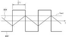
도 6은 무부하 상태일 때 송신 코일에 흐르는 전압 및 전류의 파형을 나타내는 그래프이다. 또한 도 7은 경부하 상태일 때 송신 코일에 흐르는 전압 및 전류의 파형을 나타내는 그래프이다. 또한 도 8은 중부하 상태일 때 송신 코일에 흐르는 전압 및 전류의 파형을 나타내는 그래프이다.6 is a graph showing waveforms of voltages and currents flowing in the transmitting coil when in a no-load state. 7 is a graph showing the waveforms of voltage and current flowing through the transmitting coil when in a light load state. 8 is a graph showing waveforms of voltage and current flowing in the transmission coil when in a heavy load state.
본 발명에 따른 무선 전력 수신 장치(42)와 연결된 부하(46)의 소비 전력이 0일 때, 즉 무부하 상태일 때에는 도 6과 같이 무선 전력 송신 장치(40)는 공진 특성을 나타내지 않으며, 송신 코일(L1)은 일반적인 인덕터와 유사한 특성을 나타낸다. 이에 따라서 송신 코일(L1)에 인가되는 전압(VIN)은 구동 주파수(fo)를 주기로 갖는 구형파의 파형(602)을 나타낸다. 또한 송신 코일(L1)에 흐르는 전류는 피크값(Ipeak)을 갖는 삼각파의 파형(604)을 나타낸다.When the power consumption of the
이와 같은 무부하 상태에서 무선 전력 송신 장치(40)에 의해서 무선 전력 수신 장치(42)로 전송되는 전력의 크기는 다음과 같이 표현될 수 있다.In such a no-load state, the size of the power transmitted by the wireless
[수학식 7][Equation 7]

(여기서, P는 무선 전력 송신 장치(40)에 의해서 무선 전력 수신 장치(42)로 전송되는 전력의 크기, T는 송신 코일(L1)에 인가되는 전압의 주기, t1은 임의로 설정되는 전송 시점, v1은 송신 코일(L1)에 인가되는 전압, i1은 송신 코일(L1)에 인가되는 전류)(Wherein, P is the amount of power transmitted to the wireless
한편, 도 7에는 무선 전력 수신 장치(42)가 무선 전력 송신 장치(40)로부터 전송된 전력을 부하(46)에 공급함에 따라서 부하(46)의 소비 전력이 경부하 상태일 때 송신 코일(L1)에 인가되는 전압(VIN)의 파형(702) 및 송신 코일(L1)에 흐르는 전류의 파형(704)이 각각 도시되어 있다.Meanwhile, in FIG. 7, when the wireless
부하(46)의 소비 전력이 높아짐에 따라서 송신 코일(L1)에 인가되는 전압(VIN)과 송신 코일(L1)에 흐르는 전류 간의 위상차가 감소하기 시작한다. 이 경우 송신 코일(L1)에 흐르는 전류는 피크값(Ipeak)을 초과하지 않으며 송신 코일(L1)에 인가되는 전압(VIN)과 송신 코일(L1)에 흐르는 전류 간의 위상차만으로 전력이 발생한다.As the power consumption of the
도 7과 같은 경부하 상태에서 무선 전력 송신 장치(40)에 의해서 무선 전력 수신 장치(42)로 전송되는 전력의 크기는 다음과 같이 표현될 수 있다.The size of the power transmitted to the wireless
[수학식 8][Equation 8]

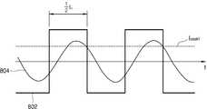
이후 부하(46)의 소비 전력이 더욱 높아지는 중부하 상태가 되면 도 8과 같은 파형이 나타난다. 부하(46)의 소비 전력이 더욱 높아짐에 따라서 송신 코일(L1)에 인가되는 전압(VIN)과 송신 코일(L1)에 흐르는 전류 간의 위상차가 더욱 감소한다. 또한 송신 코일(L1)에 흐르는 전류는 무부하 상태에서의 피크값(Ipeak)을 초과하게 된다. 이 때 전류의 파형(804)은 정현파와 유사한 형상을 나타낸다.Thereafter, when the
도 8과 같은 중부하 상태에서 무선 전력 송신 장치(40)에 의해서 무선 전력 수신 장치(42)로 전송되는 전력의 크기는 다음과 같이 표현될 수 있다.The size of the power transmitted to the wireless
[수학식 9][Equation 9]

무선 전력 송신 장치(40)를 통해 무선 전력 수신 장치(42)로 전력을 송신할 때 전력 전송 효율을 높이는 동시에 고조파를 최대한으로 억제하기 위해서는, 무선 전력 송신 장치(40)에 의해서 무선 전력 수신 장치(42)로 전송되는 전력의 최대 크기(PMAX)가 [수학식 8] 또는 [수학식 9]를 만족하도록 설정되어야 한다. 이는 다음과 같이 표현될 수 있다.When transmitting power to the wireless
[수학식 10][Equation 10]

[수학식 10]을 정리하여 송신 코일(L1)의 인덕턴스 값(L1)의 적정 범위를 산출하면 다음과 같다.Summarizing [Equation 10] and calculating an appropriate range of the inductance value L1 of the transmission coil L1 is as follows.
[수학식 11][Equation 11]

[수학식 11]에서 n은 상수로서, 인버터부(404)가 풀 브릿지 회로로 구성될 때 1로 설정되고, 인버터부(404)가 하프 브릿지 회로로 구성될 때 2로 설정되는 값이다.In [Equation 11], n is a constant, which is a value set to 1 when the
[수학식 11]을 정리하면 다음과 같이 송신 코일(L1)의 인덕턴스 값(L1)의 최종 범위를 산출할 수 있다.Summarizing [Equation 11], the final range of the inductance value L1 of the transmission coil L1 can be calculated as follows.
[수학식 12][Equation 12]

이처럼 본 발명에서는 무선 전력 송신 장치(40)를 통해 무선 전력 수신 장치(42)로 전력을 송신할 때 전력 전송 효율을 높이는 동시에 고조파를 최대한으로 억제하기 위하여 [수학식 12]의 범위를 만족하도록 송신 코일(L1)의 인덕턴스 값(L1)을 설정한다.As described above, in the present invention, when power is transmitted to the wireless
이와 같이 설정되는 송신 코일(L1)의 인덕턴스 값(L1)을 아래와 같이 전압 이득(VOUT/VIN)에 기초한 수학식에 대입하면 수신 코일(L2)의 인덕턴스 값(L2)이 산출된다.Substituting the inductance value L1 of the transmitting coil L1 set as described above into a formula based on the voltage gain VOUT / VIN as shown below, the inductance value L2 of the receiving coil L2 is calculated. .
[수학식 13][Equation 13]

(여기서, VIN은 인버터부(404)에 인가되는 전압 값, VOUT은 정류부(422)로부터 출력되는 전압 값, k는 송신 코일(L1)과 수신 코일(L2)의 결합 계수)(Wherein, VIN is a voltage value applied to the
이와 같이 [수학식 12] 및 [수학식 13]을 통해서 각각 산출되는 송신 코일(L1)의 인덕턴스 값(L1) 및 수신 코일(L2)의 인덕턴스 값(L2)을 [수학식 5] 및 [수학식 6]에 각각 대입하면 송신부(406)의 캐패시터(C1)의 캐패시턴스 값(C1) 및 수신부(426)의 캐패시터(C2)의 캐패시턴스 값(C2)을 각각 산출할 수 있다.As described above, the inductance value L1 of the transmitting coil L1 and the inductance value L2 of the receiving coil L2 calculated through
도 9는 부하의 소비 전력 변화에 따라서 무선 전력 송신 장치로부터 출력되는 출력 전압의 변화를 나타내는 그래프이다.9 is a graph showing a change in output voltage output from the wireless power transmission apparatus according to a change in power consumption of the load.
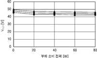
도 9는 본 발명에 따른 무선 전력 송신 장치(40)의 구동 주파수를 고정된 값(60kHz)으로 설정한 상태에서 부하(46)의 소비 전력이 0에서 80W까지 변화할 때, 무선 전력 수신 장치(42)로부터 출력되는 출력 전압(VOUT)의 크기 변화를 나타내는 그래프이다.9 is a wireless power receiving device when the power consumption of the
도 9에서 ▲로 표시된 데이터는 송신 코일(L1)과 수신 코일(L2)의 결합 계수(k)가 0.7로 설정된 경우의 데이터이다. 그리고 ■로 표시된 데이터는 송신 코일(L1)과 수신 코일(L2)의 결합 계수(k)가 0.68로 설정된 경우의 데이터이다. 또한 ●로 표시된 데이터는 송신 코일(L1)과 수신 코일(L2)의 결합 계수(k)가 0.65로 설정된 경우의 데이터이다.The data indicated by ▲ in FIG. 9 is data when the coupling coefficient k of the transmitting coil L1 and the receiving coil L2 is set to 0.7. And the data indicated by ■ is data when the coupling coefficient k of the transmitting coil L1 and the receiving coil L2 is set to 0.68. In addition, the data denoted by ● is data when the coupling coefficient k of the transmitting coil L1 and the receiving coil L2 is set to 0.65.
도 9에 도시된 바와 같이, 본 발명에 따른 무선 전력 송신 장치(40) 및 무선 전력 수신 장치(42)를 사용할 경우, 무부하 상태에서 부하의 소비 전력이 80W까지 상승하더라도 무선 전력 수신 장치(42)로부터 출력되는 출력 전압(VOUT)의 감소량이 매우 작게 나타난다. 따라서 본 발명에 따른 무선 전력 송신 장치(40) 및 무선 전력 수신 장치(42)는 고출력, 즉 50W 이상의 전력을 요구하는 부하에 안정적으로 전력을 공급할 수 있는 장점이 있다.As shown in FIG. 9, when the wireless
특히 본 발명에 따르면 전력 전송 중에 무선 전력 송신 장치(40)의 구동 주파수를 별도로 조절할 필요 없이 고정된 값으로 유지하더라도 도 9와 같이 고출력 부하에 대한 안정적인 전압 공급이 가능하다는 장점이 있다.In particular, according to the present invention, even if the driving frequency of the wireless
또한 송신 코일(L1)과 수신 코일(L2)의 결합 계수(k) 값이 0.7, 0.68, 0.65로 각각 다르게 설정되더라도 무선 전력 수신 장치(42)로부터 출력되는 출력 전압(VOUT) 변화 경향은 유사하게 나타난다. 따라서 다양한 결합 계수(k)의 설정을 통해 무선 전력 송신 장치(40) 및 무선 전력 수신 장치(42)의 설계 자유도가 높아지는 장점이 있다.Also, even if the coupling coefficients k of the transmitting coil L1 and the receiving coil L2 are differently set to 0.7, 0.68, and 0.65, the tendency of the change of the output voltage VOUT output from the wireless
전술한 본 발명은, 본 발명이 속하는 기술 분야에서 통상의 지식을 가진 자에게 있어 본 발명의 기술적 사상을 벗어나지 않는 범위 내에서 여러 가지 치환, 변형 및 변경이 가능하므로 전술한 실시예 및 첨부된 도면에 의해 한정되는 것이 아니다.The above-described invention, the above-described embodiments and the accompanying drawings because it is possible for a person having ordinary skill in the art to which the present invention pertains, various substitutions, modifications and changes are possible without departing from the technical spirit of the present invention. It is not limited by.
Claims (12)
Translated fromKorean상기 정류부로부터 출력되는 직류 전압을 변환하여 교류 전력을 출력하는 인버터부;
상기 인버터부로부터 출력되는 교류 전력을 이용하여 무선 전력 수신 장치로 전력을 송신하는 송신부를 포함하고,
상기 송신부의 공진 주파수는 상기 무선 전력 수신 장치에 포함되는 수신부의 공진 주파수 또는 상기 인버터부의 구동 주파수보다 작은 값으로 설정되고,
상기 인버터부의 구동 주파수는 상기 수신부의 공진 주파수에 기초하여 설정되는 구동 범위 내의 값으로 설정되고,
상기 송신부는 송신 코일을 포함하고,
상기 송신 코일은 하기 [수학식 3]에 따른 인덕턴스 값을 갖도록 설정되는
무선 전력 송신 장치.
[수학식 3]

(여기서, L1은 상기 송신 코일의 인덕턴스 값, VIN은 상기 인버터에 입력되는 입력 전압의 크기, fo는 상기 인버터부의 구동 주파수, PMAX는 상기 무선 전력 수신 장치로 전송되는 전력의 최대 크기, n은 상수로서 상기 인버터부가 풀 브릿지 회로로 구성될 때 1로 설정되고 상기 인버터부가 하프 브릿지 회로로 구성될 때 2로 설정됨)
A rectifying unit rectifying the input power to output DC power;
An inverter unit converting the DC voltage output from the rectifying unit to output AC power;
It includes a transmitter for transmitting power to the wireless power receiver using the AC power output from the inverter unit,
The resonance frequency of the transmission unit is set to a value smaller than the resonance frequency of the reception unit included in the wireless power receiving device or the driving frequency of the inverter unit,
The driving frequency of the inverter unit is set to a value within a driving range that is set based on the resonance frequency of the receiving unit,
The transmitting unit includes a transmitting coil,
The transmitting coil is set to have an inductance value according to Equation 3 below.
Wireless power transmission device.
[Equation 3]
(Where L1 is the inductance value of the transmitting coil, VIN is the magnitude of the input voltage input to the inverter, fo is the drive frequency of the inverter unit, PMAX is the maximum magnitude of the power transmitted to the wireless power receiving device , n is a constant, which is set to 1 when the inverter portion is composed of a full bridge circuit and 2 when the inverter portion is composed of a half bridge circuit)
상기 인버터부의 구동 주파수는 하기 [수학식 1]에 따라서 설정되는
무선 전력 송신 장치.
[수학식 1]

(여기서, fTx는 상기 송신부의 공진 주파수, a는 상수이며 0<a<1, fo는 상기 인버터부의 구동 주파수)
According to claim 1,
The drive frequency of the inverter is set according to the following [Equation 1]
Wireless power transmission device.
[Equation 1]
(Where fTx is the resonant frequency of the transmitter, a is a constant, and 0 <a <1, fo is the drive frequency of the inverter)
상기 a는 0.2 이하로 설정되는
무선 전력 송신 장치.
According to claim 2,
A is set to 0.2 or less
Wireless power transmission device.
상기 구동 범위는 하기 [수학식 2]에 따라서 설정되는
무선 전력 송신 장치.
[수학식 2]

(여기서, fRx는 상기 수신부의 공진 주파수, b는 상수이며 0<b<1, fo는 상기 인버터부의 구동 주파수)
According to claim 1,
The driving range is set according to the following [Equation 2]
Wireless power transmission device.
[Equation 2]
(Where fRx is the resonant frequency of the receiver, b is a constant and 0 <b <1, fo is the drive frequency of the inverter)
상기 b는 0.1 이하로 설정되는
무선 전력 송신 장치.
According to claim 4,
B is set to 0.1 or less
Wireless power transmission device.
상기 수신부로부터 출력되는 교류 전력을 정류하여 직류 전력을 출력하는 정류부;
상기 직류 전력을 변환하여 부하에 공급하는 컨버터부를 포함하고,
상기 무선 전력 송신 장치의 송신부의 공진 주파수는 상기 수신부의 공진 주파수 또는 상기 무선 전력 송신 장치의 인버터부의 구동 주파수보다 작은 값으로 설정되고,
상기 무선 전력 송신 장치의 인버터부의 구동 주파수는 상기 수신부의 공진 주파수에 기초하여 설정되는 구동 범위 내의 값으로 설정되고,
상기 송신부는 송신 코일을 포함하고,
상기 송신 코일은 하기 [수학식 3]에 따른 인덕턴스 값을 갖도록 설정되는
무선 전력 수신 장치.
[수학식 3]

(여기서, L1은 상기 송신 코일의 인덕턴스 값, VIN은 상기 인버터에 입력되는 입력 전압의 크기, fo는 상기 인버터부의 구동 주파수, PMAX는 상기 무선 전력 수신 장치로 전송되는 전력의 최대 크기, n은 상수로서 상기 인버터부가 풀 브릿지 회로로 구성될 때 1로 설정되고 상기 인버터부가 하프 브릿지 회로로 구성될 때 2로 설정됨)
A receiver configured to receive power transmitted from the transmitter of the wireless power transmitter and output AC power;
A rectifying unit rectifying AC power output from the receiving unit to output DC power;
And a converter unit that converts the DC power and supplies it to a load.
The resonant frequency of the transmitter of the wireless power transmitter is set to a value smaller than the resonant frequency of the receiver or the drive frequency of the inverter of the wireless power transmitter,
The driving frequency of the inverter unit of the wireless power transmission apparatus is set to a value within a driving range set based on the resonance frequency of the receiving unit,
The transmitting unit includes a transmitting coil,
The transmitting coil is set to have an inductance value according to Equation 3 below.
Wireless power receiving device.
[Equation 3]
(Where L1 is the inductance value of the transmitting coil, VIN is the magnitude of the input voltage input to the inverter, fo is the drive frequency of the inverter unit, PMAX is the maximum magnitude of the power transmitted to the wireless power receiving device , n is a constant, which is set to 1 when the inverter portion is composed of a full bridge circuit and 2 when the inverter portion is composed of a half bridge circuit)
상기 인버터부의 구동 주파수는 하기 [수학식 1]에 따라서 설정되는
무선 전력 수신 장치.
[수학식 1]

(여기서, fTx는 상기 송신부의 공진 주파수, a는 상수이며 0<a<1, fo는 상기 인버터부의 구동 주파수)
The method of claim 7,
The drive frequency of the inverter is set according to the following [Equation 1]
Wireless power receiving device.
[Equation 1]
(Where fTx is the resonant frequency of the transmitter, a is a constant, and 0 <a <1, fo is the drive frequency of the inverter)
상기 a는 0.2 이하로 설정되는
무선 전력 수신 장치.
The method of claim 8,
A is set to 0.2 or less
Wireless power receiving device.
상기 구동 범위는 하기 [수학식 2]에 따라서 설정되는
무선 전력 수신 장치.
[수학식 2]

(여기서, fRx는 상기 수신부의 공진 주파수, b는 상수이며 0<b<1, fo는 상기 인버터부의 구동 주파수)
The method of claim 7,
The driving range is set according to the following [Equation 2]
Wireless power receiving device.
[Equation 2]
(Where fRx is the resonant frequency of the receiver, b is a constant and 0 <b <1, fo is the drive frequency of the inverter)
상기 b는 0.1 이하로 설정되는
무선 전력 수신 장치.
The method of claim 10,
B is set to 0.1 or less
Wireless power receiving device.
Priority Applications (1)
| Application Number | Priority Date | Filing Date | Title |
|---|---|---|---|
| KR1020180059064AKR102091215B1 (en) | 2018-05-24 | 2018-05-24 | Wireless power transmitting apparatus and wireless power receiving apparatus |
Applications Claiming Priority (1)
| Application Number | Priority Date | Filing Date | Title |
|---|---|---|---|
| KR1020180059064AKR102091215B1 (en) | 2018-05-24 | 2018-05-24 | Wireless power transmitting apparatus and wireless power receiving apparatus |
Publications (2)
| Publication Number | Publication Date |
|---|---|
| KR20190133979A KR20190133979A (en) | 2019-12-04 |
| KR102091215B1true KR102091215B1 (en) | 2020-03-19 |
Family
ID=69004429
Family Applications (1)
| Application Number | Title | Priority Date | Filing Date |
|---|---|---|---|
| KR1020180059064AActiveKR102091215B1 (en) | 2018-05-24 | 2018-05-24 | Wireless power transmitting apparatus and wireless power receiving apparatus |
Country Status (1)
| Country | Link |
|---|---|
| KR (1) | KR102091215B1 (en) |
Citations (2)
| Publication number | Priority date | Publication date | Assignee | Title |
|---|---|---|---|---|
| WO2016163092A1 (en)* | 2015-04-06 | 2016-10-13 | パナソニックIpマネジメント株式会社 | Non-contact power supply device |
| JP2017201854A (en)* | 2016-05-06 | 2017-11-09 | ミネベアミツミ株式会社 | Wireless power feeding device, wireless power receiving device, and wireless power transmission system |
Family Cites Families (4)
| Publication number | Priority date | Publication date | Assignee | Title |
|---|---|---|---|---|
| KR20110117732A (en)* | 2007-03-27 | 2011-10-27 | 메사추세츠 인스티튜트 오브 테크놀로지 | Wireless energy transfer |
| KR102039352B1 (en)* | 2013-01-23 | 2019-11-04 | 삼성전자주식회사 | Wireless power transmitter |
| KR102048989B1 (en)* | 2013-01-24 | 2019-11-27 | 엘지전자 주식회사 | Wireless power transfer apparatus adjusting gain of lc resonant generator using fixed frequency and method for adjusting gain of lc resonant generator |
| KR20170139319A (en)* | 2016-06-09 | 2017-12-19 | 엘지이노텍 주식회사 | A wireless power transmitter and a wireless power receiver |
- 2018
- 2018-05-24KRKR1020180059064Apatent/KR102091215B1/enactiveActive
Patent Citations (2)
| Publication number | Priority date | Publication date | Assignee | Title |
|---|---|---|---|---|
| WO2016163092A1 (en)* | 2015-04-06 | 2016-10-13 | パナソニックIpマネジメント株式会社 | Non-contact power supply device |
| JP2017201854A (en)* | 2016-05-06 | 2017-11-09 | ミネベアミツミ株式会社 | Wireless power feeding device, wireless power receiving device, and wireless power transmission system |
Also Published As
| Publication number | Publication date |
|---|---|
| KR20190133979A (en) | 2019-12-04 |
Similar Documents
| Publication | Publication Date | Title |
|---|---|---|
| US10672557B2 (en) | Wireless power transmitter and method of controlling power thereof | |
| JP6282743B2 (en) | Wireless power receiver | |
| TWI565179B (en) | Wireless power receiver and power management method thereof | |
| KR101806592B1 (en) | Apparatus for transmitting wireless power and method for transmitting wireless power | |
| JP5889249B2 (en) | Power transmission device, power transmission device for power transmission device | |
| KR20130043629A (en) | Wireless power receiving apparatus capable of providing a high q value | |
| KR101438887B1 (en) | Wireless power transmission device, power supplying device and power control method thereof | |
| WO2014010518A1 (en) | Power-receiving device and power transfer system | |
| CN104981964B (en) | Wireless power transmission device and method thereof | |
| KR20130130191A (en) | Apparatus for transmitting wireless power and method for transmitting wireless power | |
| US9899874B2 (en) | Electric power supplying device, of a wireless electric power transmission apparatus and method for supplying electric power | |
| CN112448484A (en) | Non-contact power supply device | |
| KR102483807B1 (en) | Wireless power maximum efficiency tracking by system control | |
| KR101371782B1 (en) | Apparatus for receiving wireless power and system for transmitting wireless power and method for delivering wireless power | |
| WO2014045873A1 (en) | Power receiving device and contactless power transmitting equipment | |
| KR102427343B1 (en) | Wireless charger | |
| KR102091215B1 (en) | Wireless power transmitting apparatus and wireless power receiving apparatus | |
| KR101394018B1 (en) | Power supplying apparatus and wireless power transmitting apparatus | |
| Nagashima et al. | Inductively coupled wireless power transfer with class-DE power amplifier | |
| KR20140077800A (en) | Wireless power transmitting apparatus and method | |
| JP6247441B2 (en) | Power receiving device and non-contact power transmission system | |
| KR101428181B1 (en) | Apparatus for transmitting wireless power, apparatus for supplyinging power and method for power controlling thereof and apparatus for supplying power source and method for power controlling thereof | |
| KR101405806B1 (en) | Apparatus for supplying power and apparatus for transmitting wireless power and method for supplying power | |
| KR20130012853A (en) | Wireless energy transfer device | |
| KR101393852B1 (en) | Apparatus for supplying power and apparatus for transmitting wireless power and method for supplying power |
Legal Events
| Date | Code | Title | Description |
|---|---|---|---|
| A201 | Request for examination | ||
| PA0109 | Patent application | Patent event code:PA01091R01D Comment text:Patent Application Patent event date:20180524 | |
| PA0201 | Request for examination | ||
| E902 | Notification of reason for refusal | ||
| PE0902 | Notice of grounds for rejection | Comment text:Notification of reason for refusal Patent event date:20191021 Patent event code:PE09021S01D | |
| PG1501 | Laying open of application | ||
| E701 | Decision to grant or registration of patent right | ||
| PE0701 | Decision of registration | Patent event code:PE07011S01D Comment text:Decision to Grant Registration Patent event date:20200212 | |
| PR0701 | Registration of establishment | Comment text:Registration of Establishment Patent event date:20200313 Patent event code:PR07011E01D | |
| PR1002 | Payment of registration fee | Payment date:20200313 End annual number:3 Start annual number:1 | |
| PG1601 | Publication of registration | ||
| PR1001 | Payment of annual fee | Payment date:20240207 Start annual number:5 End annual number:5 | |
| PR1001 | Payment of annual fee | Payment date:20250210 Start annual number:6 End annual number:6 |