KR102089464B1 - Side storage purge apparatus - Google Patents
Side storage purge apparatusDownload PDFInfo
- Publication number
- KR102089464B1 KR102089464B1KR1020180137560AKR20180137560AKR102089464B1KR 102089464 B1KR102089464 B1KR 102089464B1KR 1020180137560 AKR1020180137560 AKR 1020180137560AKR 20180137560 AKR20180137560 AKR 20180137560AKR 102089464 B1KR102089464 B1KR 102089464B1
- Authority
- KR
- South Korea
- Prior art keywords
- unit
- chamber
- intake
- gas
- side storage
- Prior art date
- Legal status (The legal status is an assumption and is not a legal conclusion. Google has not performed a legal analysis and makes no representation as to the accuracy of the status listed.)
- Active
Links
- 238000010926purgeMethods0.000titleclaimsabstractdescription103
- 238000003860storageMethods0.000titleclaimsabstractdescription37
- 239000000758substrateSubstances0.000claimsabstractdescription83
- 239000000356contaminantSubstances0.000claimsabstractdescription25
- 238000002347injectionMethods0.000claimsdescription53
- 239000007924injectionSubstances0.000claimsdescription53
- 238000000034methodMethods0.000claimsdescription12
- 239000007789gasSubstances0.000abstractdescription116
- 239000007921spraySubstances0.000abstractdescription9
- 239000002245particleSubstances0.000abstractdescription5
- 230000007547defectEffects0.000abstractdescription4
- 238000007599dischargingMethods0.000abstractdescription3
- 239000000126substanceSubstances0.000abstractdescription2
- IJGRMHOSHXDMSA-UHFFFAOYSA-NAtomic nitrogenChemical compoundN#NIJGRMHOSHXDMSA-UHFFFAOYSA-N0.000description6
- 229910001873dinitrogenInorganic materials0.000description4
- 238000004519manufacturing processMethods0.000description3
- 239000004065semiconductorSubstances0.000description3
- 239000006227byproductSubstances0.000description2
- 238000005530etchingMethods0.000description2
- 239000003517fumeSubstances0.000description2
- QVGXLLKOCUKJST-UHFFFAOYSA-Natomic oxygenChemical compound[O]QVGXLLKOCUKJST-UHFFFAOYSA-N0.000description1
- 238000004140cleaningMethods0.000description1
- 238000012864cross contaminationMethods0.000description1
- 230000008021depositionEffects0.000description1
- 238000000151depositionMethods0.000description1
- 230000000694effectsEffects0.000description1
- 229910052757nitrogenInorganic materials0.000description1
- 239000001301oxygenSubstances0.000description1
- 229910052760oxygenInorganic materials0.000description1
- 238000004148unit processMethods0.000description1
Images


Classifications
- H—ELECTRICITY
- H01—ELECTRIC ELEMENTS
- H01L—SEMICONDUCTOR DEVICES NOT COVERED BY CLASS H10
- H01L21/00—Processes or apparatus adapted for the manufacture or treatment of semiconductor or solid state devices or of parts thereof
- H01L21/67—Apparatus specially adapted for handling semiconductor or electric solid state devices during manufacture or treatment thereof; Apparatus specially adapted for handling wafers during manufacture or treatment of semiconductor or electric solid state devices or components ; Apparatus not specifically provided for elsewhere
- H01L21/67005—Apparatus not specifically provided for elsewhere
- H01L21/67011—Apparatus for manufacture or treatment
- H01L21/67017—Apparatus for fluid treatment
- H01L21/67028—Apparatus for fluid treatment for cleaning followed by drying, rinsing, stripping, blasting or the like
- H—ELECTRICITY
- H01—ELECTRIC ELEMENTS
- H01L—SEMICONDUCTOR DEVICES NOT COVERED BY CLASS H10
- H01L21/00—Processes or apparatus adapted for the manufacture or treatment of semiconductor or solid state devices or of parts thereof
- H01L21/67—Apparatus specially adapted for handling semiconductor or electric solid state devices during manufacture or treatment thereof; Apparatus specially adapted for handling wafers during manufacture or treatment of semiconductor or electric solid state devices or components ; Apparatus not specifically provided for elsewhere
- H01L21/67005—Apparatus not specifically provided for elsewhere
- H01L21/67242—Apparatus for monitoring, sorting or marking
- H01L21/67253—Process monitoring, e.g. flow or thickness monitoring
Landscapes
- Engineering & Computer Science (AREA)
- Physics & Mathematics (AREA)
- Condensed Matter Physics & Semiconductors (AREA)
- General Physics & Mathematics (AREA)
- Manufacturing & Machinery (AREA)
- Computer Hardware Design (AREA)
- Microelectronics & Electronic Packaging (AREA)
- Power Engineering (AREA)
- Container, Conveyance, Adherence, Positioning, Of Wafer (AREA)
Abstract
Description
Translated fromKorean본 발명은 사이드 스토리지 퍼지 장치에 관한 것으로, 더욱 상세하게는 기판에 잔존하는 이물질을 제거하기 위하여 기판 이송 경로 상에 배치되는 사이드 스토리지 내부에 퍼지 가스를 공급 및 배출하는 사이드 스토리지 퍼지 장치에 관한 것이다.The present invention relates to a side storage purge device, and more particularly, to a side storage purge device for supplying and discharging purge gas inside the side storage disposed on the substrate transport path in order to remove foreign substances remaining on the substrate.
일반적으로 반도체 제조 공정은 식각, 증착, 에칭과 같은 다양한 단위 공정들이 순차적으로 반복된다. 각 공정 처리 과정에서 기판 상에 이물질 또는 오염물질이 잔존하게 되어 기판에 불량 발생하거나 손상되어 기판 수율이 낮아지는 문제가 있었다.In general, in a semiconductor manufacturing process, various unit processes such as etching, deposition, and etching are sequentially repeated. In each process process, foreign matter or contaminants remained on the substrate, resulting in defects or damage to the substrate, resulting in a low yield of the substrate.
따라서, 반도체 제조 공정 후, 기판에 잔존하는 부산물 및 오염 물질을 제거하기 위하여, 기판 이송 경로 상에 사이드 스토리지를 구성하였다. 사이드 스토리지는 내부 공간에 기판 퍼지 기능을 수행하여 부산물 및 오염 물질의 제거, 교차 오염 방지, 습도와 산소 농도 제어하는 효과를 얻을 수 있다. 일반적인 사이드 스토리지는 기판을 수납하는 FOUP(Front Opening Unified Pod) 이송 모듈인 EFEM(Equipment Front End Module) 장치의 측부에 위치하며, 복수의 기판을 적층하여 수납한다.Therefore, after the semiconductor manufacturing process, in order to remove by-products and contaminants remaining on the substrate, the side storage was configured on the substrate transport path. The side storage performs the purging function of the substrate in the interior space, thereby removing byproducts and contaminants, preventing cross contamination, and controlling humidity and oxygen concentration. The general side storage is located on the side of the EFEM (Equipment Front End Module) device, which is a front opening unified pod (FOUP) transfer module for receiving a substrate, and stacks and stores a plurality of substrates.
종래의 한국 공개특허공보 제10-2015-0087015호에는 웨이퍼가 적재되는 웨이퍼 카세트, 및 웨이퍼 카세트에 적재된 웨이퍼의 퓸을 배기하는 배기부를 포함하며, 웨이퍼 카세트는 양측면에 구비되어 웨이퍼가 적재되는 적재대, 및 전방에 구비되어 적재대에 적재되는 웨이퍼가 출입하는 전방 개구부를 포함하며, 적재대는 적재대에 적재된 웨이퍼에 퍼지가스를 공급하는 퍼지 가스 배출구가 구비되는 퓸 제거 장치에 대하여 기재되어 있다.Conventional Korean Patent Publication No. 10-2015-0087015 includes a wafer cassette on which a wafer is loaded, and an exhaust portion for evacuating fume of the wafer loaded on the wafer cassette, wherein the wafer cassette is provided on both sides to load the wafer. It is described with respect to a fume removal device having a purge and a purge gas outlet for supplying a purge gas to a wafer stacked on the stack, and a front opening for entering and exiting a wafer stacked on the stack. .
한국 등록특허공보 제10-1682473호에는 사이드 스트리지 내부에 기판을 수용하는 수용공간을 갖고, 기판을 세정하는 퍼지 가스를 공급하는 가스 공급부 및 외부와 연통되어 기판으로부터 분리된 오염물과 퍼지 가스를 배출하는 다수의 배기용 개구를 구비하는 챔버, 챔버의 내측벽을 따라 일정한 간격으로 배치되어 기판을 개별적으로 적재하는 다수의 기판 지지부재 및 각 기판 지지부재에 배치되어 가스 공급부와 개별적으로 연결되고 기판의 상면으로 퍼지 가스를 분사하는 적어도 하나의 가스분사구를 구비하는 기판 지지부재 및 배기용 개구와 연결되어 오염물을 외부로 방출하는 배기유닛을 포함하는 사이드 스토리지 및 이를 구비하는 반도체 소자 제조 설비에 대하여 기재되어 있다.Korean Patent Publication No. 10-1682473 has a receiving space for accommodating the substrate inside the side strip, and a gas supply unit for supplying a purge gas for cleaning the substrate and communicating with the outside to discharge contaminants and purge gas separated from the substrate A chamber having a plurality of exhaust openings, a plurality of substrate support members arranged at regular intervals along the inner wall of the chamber to individually load the substrates, and disposed on each substrate support member to be individually connected to the gas supply unit and to It is described with respect to a substrate storage member having at least one gas injection port for injecting a purge gas to an upper surface and a side storage including an exhaust unit for discharging contaminants to the outside and a semiconductor device manufacturing facility having the same. have.
한국 공개특허공보 제10-2006-0078936호에는 버퍼챔버에서 질소가스를 버퍼챔버에 공급하기 위한 퍼지홀, 퍼지홀에 연결되는 질소가스 공급관, 공급관에 설치되어 질소가스의 유량을 제어하는 유량제어기를 포함하여 이루어진 버퍼챔버의 퍼지시스템으로 퍼지홀이 바닥면에 다수개 형성되고 버퍼챔버의 상부에 설치되어 버퍼챔버 내부에 질소가스를 골고루 분사시켜 주는 질소공급튜브를 포함하여 이루어진 버퍼챔버의 퍼지시스템에 대하여 기재되어 있다.In Korean Patent Publication No. 10-2006-0078936, a purge hole for supplying nitrogen gas from a buffer chamber to a buffer chamber, a nitrogen gas supply pipe connected to the purge hole, and a flow controller that is installed in the supply pipe to control the flow of nitrogen gas A purge system of a buffer chamber made up of a plurality of purge holes formed on a bottom surface and installed on top of the buffer chamber to purge system of a buffer chamber comprising a nitrogen supply tube that evenly injects nitrogen gas into the buffer chamber. It is described.
상술한 종래 기술은, 사이드 스토리지 내에 퍼지 가스를 공급하나, 배기부가 사이드 스토리지의 일측에 배치되었다. 이는 사이드 스토리지 내에 적재된 모든 기판의 표면 중 일부만을 지나게 되어, 기판에 잔류하는 파티클 및 오염물질이 충분히 제거될 수 없었다. 이로써, 불량 발생률이 높고, 기판 수율이 낮은 문제점이 있었다.In the above-described prior art, purge gas is supplied into the side storage, but the exhaust portion is disposed on one side of the side storage. This passed only a part of the surface of all the substrates loaded in the side storage, so that particles and contaminants remaining on the substrates could not be sufficiently removed. As a result, there was a problem that the defect generation rate is high and the substrate yield is low.
본 발명은 퍼지 가스가 사이드 스토리지 내에 적재된 기판의 상, 하부 표면을 고르게 지나도록 퍼지가스를 공급 및 배기하여 기판의 수율을 향상시키는 사이드 스토리지 퍼지 장치를 제공함에 그 목적이 있다.An object of the present invention is to provide a side storage purge device that improves the yield of the substrate by supplying and exhausting purge gas so that the purge gas passes evenly over the upper and lower surfaces of the substrate loaded in the side storage.
상술한 과제를 해결하기 위한 본 발명의 사이드 스토리지 퍼지 장치는, 전면에 기판이 출입하는 출입구가 형성되고, 내부에 복수의 기판이 적재되는 적재공간이 형성된 챔버부; 상기 적재공간에 적재된 상기 기판 사이에 퍼지 가스를 분사하도록, 상기 챔버부의 후방에 구비된 제1 분사부와 상기 챔버부의 전방에 구비된 제2 분사부를 포함하는 가스 분사부; 상기 챔버부 전방에 구비되어 상기 제1 분사부로부터 분사된 퍼지 가스를 흡기하는 제1 흡기부와, 상기 챔버부 후방에 구비되어 상기 제2 분사부로부터 분사된 퍼지 가스를 흡기하는 제2 흡기부를 포함하는 가스 흡기부; 및 상기 가스 분사부와 상기 가스 흡기부의 작동을 제어하는 제어부; 를 포함한다.The side storage purge device of the present invention for solving the above-described problem is provided with an entrance and exit through which a substrate is formed on the front surface, and a chamber portion in which a loading space in which a plurality of substrates are loaded is formed; A gas injection unit including a first injection unit provided at the rear of the chamber unit and a second injection unit provided at the front of the chamber unit to inject a purge gas between the substrates loaded in the loading space; A first intake unit provided in front of the chamber unit to intake purge gas injected from the first injection unit, and a second intake unit provided at the rear of the chamber unit to intake purge gas injected from the second injection unit. Gas intake unit comprising; And a control unit controlling operations of the gas injection unit and the gas intake unit. It includes.
바람직하게, 상기 제어부는, 상기 제1 분사부와 상기 제1 흡기부가 함께 작동하는 제1 모드와, 상기 제2 분사부와 상기 제2 흡기부가 함께 작동하는 제2 모드를 선택적으로 동작시킨다.Preferably, the control unit selectively operates a first mode in which the first injection unit and the first intake unit operate together, and a second mode in which the second injection unit and the second intake unit operate together.
바람직하게, 상기 제1 분사부는, 상기 챔버부의 후방 양측에 상기 기판의 적재 방향을 따라 복수의 제1, 제2 노즐이 배치되고, 상기 제1 흡기부는, 상기 챔버부 전방의 양측면에 상기 적재 방향을 따라 각각 배치된 복수의 제1, 제2 흡입구를 포함한다.Preferably, the first injection unit, a plurality of first and second nozzles are disposed on both sides of the rear of the chamber along the loading direction of the substrate, and the first intake unit has the loading direction on both side surfaces in front of the chamber unit. It includes a plurality of first and second suction ports respectively disposed along.
바람직하게, 상기 제1, 제2 노즐 각각은, 서로 다른 복수의 방향으로 퍼지 가스를 분사한다.Preferably, each of the first and second nozzles injects purge gas in a plurality of different directions.
바람직하게, 상기 제1, 제2 흡입구는, 상기 챔버부의 상부로 갈수록 넓게 형성된다.Preferably, the first and second suction ports are formed wider toward the upper portion of the chamber.
바람직하게, 상기 제1 흡기부는, 상기 챔버부의 하부면 전방에 배치된 제3 흡입구를 더 포함한다.Preferably, the first intake part further includes a third intake port disposed in front of the lower surface of the chamber part.
바람직하게, 상기 제1 내지 제3 흡입구는, 상기 적재공간으로부터 흡기된 퍼지 가스 및 오염 물질이 배기되는 배기 통로를 공유한다.Preferably, the first to third intake ports share an exhaust passage through which purge gas and contaminants intake from the loading space are exhausted.
바람직하게, 상기 제3 흡입구는, 상기 적재공간의 퍼지 가스 및 오염 물질의 흡기 유량을 조절하도록, 개구 면적을 조절한다.Preferably, the third intake port controls the opening area to control the intake flow rate of the purge gas and contaminants in the loading space.
바람직하게, 상기 제2 분사부는, 상기 챔버부 전방의 양측면에 상기 적재 방향을 따라 각각 복수의 제3, 제4 노즐이 배치되고, 상기 제2 흡기부는, 상기 챔버부 후방의 중앙부에 상기 적재 방향을 따라 복수의 제4 흡입구가 배치된다.Preferably, the second injection unit, a plurality of third and fourth nozzles are respectively disposed along the loading direction on both sides of the front of the chamber unit, and the second intake unit includes the loading direction in a central portion behind the chamber unit. A plurality of fourth inlets are arranged along.
바람직하게, 상기 제3, 제4 노즐은, 적어도 상기 적재 공간의 내측 방향과 상기 출입구를 가로지르는 방향으로 퍼지 가스를 분사한다.Preferably, the third and fourth nozzles spray a purge gas in at least an inner direction of the loading space and a direction crossing the doorway.
바람직하게, 상기 제4 흡입구는, 상기 챔버부의 상부로 갈수록 넓게 형성된다.Preferably, the fourth suction port is formed wider toward the upper portion of the chamber.
본 발명의 사이드 스토리지 퍼지 장치에 의하면, 퍼지 가스가 사이드 스토리지에 적재된 기판의 상, 하부 표면을 고르게 지나도록 공급 및 배기됨으로써, 기판에 잔존하는 파티클 및 오염 물질을 고르게 제거하여 기판의 불량을 감소시키고, 수율을 향상시킬 수 있다.According to the side storage purge device of the present invention, the purge gas is supplied and exhausted evenly over the upper and lower surfaces of the substrate loaded in the side storage, thereby uniformly removing particles and contaminants remaining on the substrate to reduce defects in the substrate. And improve the yield.
또한, 본 발명은 적재 공간의 전, 후방 각각에 가스 분사부와 가스 흡기부를 구비하여 퍼지 가스가 후방에서 분사되어 전방으로 배기되는 제1 모드와 전방에서 분사되어 후방으로 배기되는 제2 모드를 선택적으로 동작시킬 수 있다.In addition, the present invention is provided with a gas injection unit and a gas intake unit at each of the front and rear of the loading space to selectively select a first mode in which the purge gas is injected from the rear and exhausted forward and a second mode in which the exhaust gas is ejected backwards. Can be operated with.
또한, 본 발명은 제1 모드에서 분사된 퍼지가스가 도달하지 못한 기판 표면에 제2 모드에서 분사된 퍼지가스가 지나가도록 하여 기판의 전체 표면을 고르게 퍼지할 수 있다.In addition, the present invention can purge the entire surface of the substrate evenly by allowing the purge gas injected in the second mode to pass through the substrate surface to which the purge gas injected in the first mode does not reach.
또한, 본 발명은 제4 흡입구가 챔버부 상부로 갈수록 넓게 형성되어 챔버부 상, 하부를 균일하게 배기할 수 있다.In addition, according to the present invention, the fourth suction port is formed wider toward the upper portion of the chamber to uniformly exhaust the upper and lower portions of the chamber.
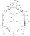
도 1은 본 발명의 사이드 스토리지 퍼지 장치를 나타낸 평단면도.
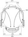
도 2는 본 발명의 사이드 스토리지 퍼지 장치를 나타낸 정면도.
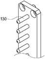
도 3은 본 발명을 구성하는 기판 지지핀을 나타낸 사시도.
도 4는 본 발명을 구성하는 노즐을 정면에 바라본 도면.
도 5는 본 발명을 구성하는 노즐의 평단면도.
도 6의 (a)는 본 발명을 구성하는 제1 흡입구를 나타낸 사시도.
도 6의 (b)는 본 발명을 구성하는 제2 흡입구를 나타낸 사시도.
도 7의 (a)는 본 발명을 구성하는 제1 흡입구를 나타낸 평단면도.
도 7의 (b)는 본 발명을 구성하는 제2 흡입구를 나타낸 평단면도.
도 8은 본 발명을 구성하는 제1 흡입구를 나타낸 사시도.
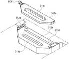
도 9는 본 발명을 구성하는 제3 흡입구를 나타낸 분해도.
도 10은 본 발명을 구성하는 제3 흡입구가 폐쇄된 상태를 나타낸 평면도.
도 11은 본 발명을 구성하는 제3 흡입구가 개방된 상태를 나타낸 평면도.
도 12는 제1 모드에서 퍼지 가스의 기류 방향을 나타내는 도면.
도 13은 제2 모드에서 퍼지 가스의 기류 방향을 나타내는 도면.1 is a cross-sectional plan view showing a side storage purge device of the present invention.
Figure 2 is a front view showing a side storage purge device of the present invention.
Figure 3 is a perspective view showing a substrate support pin constituting the present invention.
4 is a front view of the nozzle constituting the present invention.
5 is a cross-sectional plan view of a nozzle constituting the present invention.
Figure 6 (a) is a perspective view showing a first inlet constituting the present invention.
Figure 6 (b) is a perspective view showing a second inlet constituting the present invention.
Figure 7 (a) is a cross-sectional plan view showing a first inlet constituting the present invention.
Figure 7 (b) is a cross-sectional plan view showing a second inlet constituting the present invention.
8 is a perspective view showing a first inlet constituting the present invention.
Figure 9 is an exploded view showing a third inlet constituting the present invention.
10 is a plan view showing a state in which the third inlet constituting the present invention is closed.
11 is a plan view showing a state in which the third inlet constituting the present invention is opened.
12 is a view showing a direction of air flow of the purge gas in the first mode.
Fig. 13 is a view showing the direction of air flow of the purge gas in the second mode.
이하에서는 본 발명의 실시예를 도면을 참고하여 구체적으로 설명한다. 본 발명의 사이드 스토리지 퍼지 장치는 사이드 스토리지 내부에 퍼지 가스를 공급하여 기판에 잔존하는 파티클 및 오염 물질을 제거하고, 오염 물질과 퍼지 가스를 사이드 스토리지로부터 배기하는 장치에 관한 것이다.Hereinafter, embodiments of the present invention will be described in detail with reference to the drawings. The side storage purge apparatus of the present invention relates to an apparatus for supplying a purge gas inside the side storage to remove particles and contaminants remaining on the substrate, and to exhaust contaminants and purge gas from the side storage.
본 발명의 실시예에 의한 사이드 스토리지 퍼지 장치는, 도 1, 도 2에 도시한 바와 같이, 크게 챔버부(100), 가스 분사부(200), 가스 흡기부(300) 및 제어부(400)로 이루어진다. Side storage purge device according to an embodiment of the present invention, as shown in Figures 1 and 2, the
챔버부(100)는 전면에 기판이 출입하는 출입구(110)가 형성되고, 내부에 복수의 기판이 적재되는 적재공간(120)이 형성된다.The
적재공간(120)에는 기판을 지지하는 기판 지지핀(130)이 형성된다. 기판 지지핀(130)은 적재공간(120)에 적재된 기판 둘레에 복수개 배치되어 기판을 지지한다. 기판 지지핀(130)은 도 3에 도시한 바와 같이, 챔버부(100)의 내벽면으로부터 돌출 형성된 것이 바람직하며, 기판의 하부면을 지지하는 형태라면 어떠한 형태라도 가능하다.A
가스 분사부(200)는 적재공간(120)에 적재된 기판 사이에 퍼지 가스를 분사하도록, 제1 분사부(210)와 제2 분사부(220)를 포함한다.The
제1 분사부(210)는 챔버부(100)의 후방 양측에 배치되며, 기판의 적재 방향을 따라 배치된 복수의 제1 노즐(211)과 제2 노즐(212)을 포함한다.The
제1, 제2 노즐(211, 212) 각각은, 도 4, 도 5에 도시한 바와 같이, 몸체부(210a), 가스통로(210b), 가스분사구(210c)로 이루어진다.Each of the first and
몸체부(210a)는 챔버부(100) 내부에 기판의 적재 방향을 따라 길게 형성된다.The
가스통로(210b)는 몸체부(210a) 내부에 기판의 적재 방향을 따라 길게 형성된다.The
가스분사구(210c)는 가스통로(220)로부터 분기되어 적재 방향을 따라 복수개가 배치되며 적재공간(120)에 적재된 기판 사이에 퍼지 가스를 분사한다. 이때, 가스분사구(210c)는 각 기판의 상, 하부에 배치되어 전체 기판의 상, 하부면에 퍼지 가스가 고르게 분사된다.The
또한, 제1, 제2 노즐(211, 212) 각각은, 동일한 높이에 복수의 가스분사구(210c)가 배치되고, 복수의 가스분사구(210c)가 서로 다른 방향으로 퍼지 가스를 분사한다. 이로써, 퍼지 가스가 다양한 방향으로 분사되어, 기판의 전체면에 고르게 분사될 수 있다. 구체적으로, 도 4, 도 5에 도시한 바와 같이, 동일한 높이에 3개의 가스분사구(210c)가 형성되고, 이 중 하나는 적재된 기판의 중앙부를 향하고, 다른 2개는 중앙부를 향하는 가스분사구로부터 양측으로 각각 45°경사진 방향으로 퍼지 가스를 분사한다.Further, each of the first and
이러한 가스분사구(210c)는 출구의 단면이 넓어지는 형상으로 형성되는 것이 바람직하며, 더욱 바람직하게는 원뿔 형상으로 형성될 수 있다. 이로써, 퍼지 가스를 넓은 범위에 고르게 분사할 수 있다.The
한편, 도면에 도시하지는 않았지만, 몸체부에 형성되어 가스통로로 퍼지 가스를 유입시키는 유입구를 더 포함할 수 있다. 유입구를 2 이상으로 형성하면, 퍼지 가스를 가스통로로 유입시키는 공급 유로가 분기되어 가스통로의 내부 유량 균일성을 향상시킬 수 있다.On the other hand, although not shown in the drawing, it may be formed on the body portion may further include an inlet for introducing a purge gas into the gas passage. When two or more inlets are formed, the supply flow path for introducing the purge gas into the gas passage branches off, thereby improving the uniformity of the internal flow rate of the gas passage.
제2 분사부(220)는 챔버부(100) 전방의 양측면에 배치되며, 기판의 적재 방향을 따라 각각 복수의 제3 노즐(221)과 제4 노즐(222)을 포함한다.The
제3, 제4 노즐(221, 222) 각각은, 도 6, 도 7에 도시한 바와 같이, 몸체부(221a, 222a), 가스통로(221b, 222b), 가스분사구(211c, 222c, 221d, 222d)로 이루어진다.Each of the third and
몸체부(221a, 222a)는 챔버부(100) 양측면의 전방에 기판의 적재 방향을 따라 길게 형성된다.The
가스통로(221b, 222b)는 몸체부(221a, 222a) 내부에 기판의 적재 방향을 따라 길게 형성된다.The
가스분사구(211c, 222c, 221d, 222d)는 가스통로(221b, 222b)로부터 분기되어 적재 방향을 따라 복수개가 배치되며, 적재공간(120)에 적재된 기판 사이에 퍼지 가스를 분사한다. 이때, 가스분사구는 각 기판의 상, 하부에 배치되어 전체 기판의 상, 하부면에 퍼지 가스가 고르게 분사된다.The
또한, 제3, 제4 노즐(221, 222) 각각은, 동일한 높이에 복수의 가스분사구가 배치되고, 복수의 가스분사구가 서로 다른 방향으로 퍼지 가스를 분사하여 기판의 더 넓은 면적에 퍼지 가스가 고르게 분사될 수 있다.In addition, each of the third and
구체적으로, 도 1, 도 6, 도 7에 도시한 바와 같이, 제3, 제4 노즐(221, 222) 각각은, 동일한 높이에 2개의 가스분사구가 형성된다. 이 중 하나의 가스분사구(221c, 222c)는 챔버부(100)의 출입구(110)를 가로지르는 방향으로 형성되고, 다른 하나의 가스분사구(221d, 222d)는 적재 공간의 내측 방향으로 형성되어 퍼지 가스를 분사한다. 이로써, 적재 공간 내측으로 분사되는 퍼지 가스는 기판의 상, 하부를 지나며 기판을 퍼지한다. 또한, 출입구를 가로지르는 방향으로 분사되는 퍼지 가스는 출입구 외측으로부터 유입될 수 있는 파티클이나 오염물질의 유입을 방지하는 효과를 얻을 수 있다.Specifically, as shown in FIGS. 1, 6, and 7, each of the third and
이러한 가스분사구(221c, 222c, 221d, 222d)는 출구의 단면이 넓어지는 형상으로 형성되는 것이 바람직하며, 더욱 바람직하게는 원뿔 형상으로 형성될 수 있다. 이로써, 퍼지 가스를 넓은 범위에 고르게 분사할 수 있다.The
한편, 도면에 도시하지는 않았지만, 몸체부에 형성되어 가스통로로 퍼지 가스를 유입시키는 유입구를 더 포함할 수 있다. 유입구를 2 이상으로 형성하면, 퍼지 가스를 가스통로로 유입시키는 공급 유로가 분기되어 가스통로의 내부 유량 균일성을 향상시킬 수 있다.On the other hand, although not shown in the drawing, it may be formed on the body portion may further include an inlet for introducing a purge gas into the gas passage. When two or more inlets are formed, the supply flow path for introducing the purge gas into the gas passage branches off, thereby improving the uniformity of the internal flow rate of the gas passage.
가스 흡기부(300)는 적재공간(120)의 퍼지 가스 및 오염 물질을 흡기하여 챔버부(100) 외부로 배기하며, 제1 흡기부(310)와 제2 흡기부(320)를 포함한다.The
제1 흡기부(310)는 챔버부(100) 전방에 구비되며, 제1 분사부(210)로부터 분사된 퍼지 가스를 흡기한다. 제1 흡기부(310)는 제1 흡입구(311)와 제2 흡입구(312) 및 제3 흡입구(313)를 포함한다.The
제1, 제2 흡입구(311, 312)는, 도 8에 도시한 바와 같이, 챔버부(100) 전방의 양측면에 배치되며, 기판의 적재 방향을 따라 각각 복수개 배치된다.As shown in FIG. 8, the first and
제1, 제2 흡입구(311, 312)으로 흡입된 퍼지 가스 및 오염 물질이 챔버부(100) 외측에 구비된 흡입 공간을 통해 챔버부(100) 하부로 배기된다. 이로써, 적재 공간(120) 상부보다 하부의 흡입량이 강하므로, 제1, 제2 흡입구(311, 312) 각각은, 챔버부(100)의 상부로 갈수록 넓게 형성되어 흡입구를 통한 챔버부(100) 상, 하부의 흡입량이 균일하도록 할 수 있다.The purge gas and contaminants sucked into the first and
제3 흡입구(313)는, 도 9 내지 도 11에 도시한 바와 같이, 챔버부(100) 하부면 전방에 배치되며, 적재 공간의 퍼지 가스 및 오염 물질의 흡기 유량을 조절하도록, 개구 면적을 조절한다.9 to 11, the
구체적으로, 제3 흡입구(313)는 제1 개구부(313c)가 형성된 제1 플레이트(313a), 제2, 제3 개구부(313d, 313e)가 형성된 제2 플레이트(313b)로 구성될 수 있다. 제1, 제2 플레이트(313a, 313b)의 상대 슬라이딩에 의해 제1 개구부(313c)와 제2, 제3 개구부(313d, 313e)가 겹쳐지는 개구 면적을 조절하여 제3 흡입구(313)의 흡기 유량을 조절한다.Specifically, the
예컨대, 도 9에 도시한 바와 같이, 제1 플레이트(313a)는 측면에 조작기(313f)가 돌출 형성되며, 조작기(313f)를 조작하여 제1 플레이트(313a)를 전, 후방향으로 슬라이딩시킬 수 있다.For example, as shown in FIG. 9, the
제2 플레이트(313b)는 챔버부(100)에 고정된 상태를 유지하며, 측부에 조작기(313f)가 삽입되어 제1 플레이트(313a)의 슬라이딩을 가이드한다. 제2 플레이트(313b)의 일측에는 제1 플레이트(313a)가 슬라이딩하는 방향을 따라 눈금 표시부(313g)가 형성된다. 눈금 표시부(313g)는 조작기(313f)의 위치에 따라 제1 개구부(313c)와 제2, 제3 개구부(313d, 313e)의 개구 정도를 표시하여 사용자가 개구 면적을 쉽게 인지하고, 조절할 수 있게 한다.The
도 10은 제1 플레이트(313a)에 의해 제2, 제3 개구부(313d, 313e)가 폐쇄된 상태를 나타낸다. 이로부터 제1 플레이트(313a)를 전방으로 슬라이딩시키면, 도 11에 도시한 바와 같이, 제3 개구부(313e)는 제1 개구부(313c)와 겹쳐지며 개구되고, 제2 개구부(313d)는 노출되며 개구된다. 즉, 제1 플레이트(313a)의 전, 후방 위치를 조절하여 개구부의 개구 면적을 조절함으로써, 제3 흡입구(313)의 흡기 유량을 조절한다.10 shows a state in which the second and
제1 내지 제3 흡입구(311, 312, 313)는 적재 공간(120)으로부터 흡기된 퍼지 가스 및 오염 물질이 배기되는 배기 통로(310a)를 공유한다. 제1, 제2 흡입구(311, 312)로 흡입된 퍼지 가스는 챔버부(100) 외측의 흡입 공간을 통해 하부로 배기되고, 제3 흡입구(313)로 흡입된 퍼지 가스는 제2 플레이트(313b) 하부로 배기되어 제1 배기 통로(310a)로 합류된다. 이로써, 제1 흡기부(310)를 통해 배기된 퍼지 가스는 하나의 배기 통로(310a)로 배기된다.The first to
제2 흡기부(320)는 챔버부(100) 후방에 구비되며, 제2 분사부(220)로부터 분사된 퍼지 가스를 흡기한다. 제2 흡기부(320)는 제4 흡입구(321)를 포함한다.The
제4 흡입구(321)는, 도 1, 도 2에 도시한 바와 같이, 챔버부(100) 후방면에 기판의 적재 방향을 따라 복수개가 배치된다.As shown in FIGS. 1 and 2, a plurality of
제4 흡입구(321)로 흡입된 퍼지 가스 및 오염 물질이 챔버부(100) 외측에 구비된 흡입 공간을 통해 챔버부(100) 하부로 배기된다. 이로써, 적재 공간(120) 상부보다 하부의 흡입량이 강하므로, 제4 흡입구(321)는 챔버부(100)의 상부로 갈수록 넓게 형성되어 흡입구를 통한 챔버부(100) 상, 하부의 흡입량이 균일하도록 할 수 있다.The purge gas and contaminants sucked through the
제4 흡입구(321)로 흡입된 퍼지 가스 및 오염 물질은 챔버부(100) 외측의 흡입 공간을 통해 제2 배기 통로(320a)로 배기된다. 제2 배기 통로(320a)는 후단에서 제1 배기 통로(310a)로 합류되는 것이 바람직하다.The purge gas and contaminants sucked through the
제어부는 가스 분사부(200)와 가스 흡기부(300)의 작동을 제어한다. 구체적으로, 제1 모드와 제2 모드를 선택적으로 동작시킬 수 있다.The control unit controls the operation of the
제1 모드는 도 12에 도시한 바와 같이, 제1 분사부(210)와 제1 흡기부(310)가 함께 작동되는 모드이다. 제1 모드는 챔버부(100) 후방에서 분사된 퍼지 가스가 챔버부(100) 전방을 통해 배기된다.As illustrated in FIG. 12, the first mode is a mode in which the
제2 모드는 도 13에 도시한 바와 같이, 제2 분사부(220)와 제2 흡기부(320)가 함께 작동되는 모드이다. 제2 모드는 챔버부(100) 전방에서 분사된 퍼지 가스가 챔버부(100) 후방을 통해 배기된다.As shown in FIG. 13, the second mode is a mode in which the
제어부는 챔버부(100)의 상황에 따라 제1, 제2 모드를 선택하여 작동시킬 수 있고, 제1 모드 작동 후 제2 모드를 작동시키거나, 제2 모드 작동 후 제1 모드를 작동시킬 수 있다.The control unit may select and operate the first and second modes according to the situation of the
제1 모드에서 분사된 퍼지 가스와 제2 모드에서 분사된 퍼지 가스 각각은 기판의 서로 다른 표면을 지나게 되므로, 한가지 모드로 퍼지시키는 경우보다 더 넓은 범위를 고르게 퍼지시킬 수 있다.Since each purge gas injected in the first mode and the purge gas injected in the second mode pass through different surfaces of the substrate, a wider range can be evenly purged than when purging in one mode.
한편, 제어부는 기판이 챔버부(100)로 인입될 때, 제1 모드를 작동시키고, 기판이 챔버부(100)로부터 인출될 때, 제2 모드를 작동시킬 수 있다.Meanwhile, the control unit may operate the first mode when the substrate is drawn into the
이에, 인입되는 기판에 부착된 오염 물질 등은 전방의 제1 흡기부(310)로 배기되거나 출입구(110)를 통해 외부로 배출되어, 오염 물질이 기판과 함께 챔버부(100)로 인입되는 것을 방지할 수 있고, 인출되는 기판에 부착된 오염 물질 등은 후방의 제2 흡기부(320)로 배기되어, 오염 물질이 기판과 함께 챔버부(100) 외부로 인출되는 것을 방지할 수 있다.Accordingly, the contaminants attached to the substrate to be introduced are discharged to the
또한, 기판이 챔버부(100)를 출입하는 방향과 퍼지 가스의 기류 방향이 서로 반대 방향이므로, 기판의 퍼지 효율을 더욱 향상시킬 수 있다.In addition, since the direction in which the substrate enters and exits the
이상에서는 본 발명의 구체적인 실시예를 도면을 중심으로 설명하였으나, 본 발명의 권리범위는 특허 청구 범위에 기재된 기술적 사상을 중심으로 그 변형물 또는 균등물에까지 미침은 자명하다 할 것이다.In the above, a specific embodiment of the present invention has been mainly described with reference to the drawings, but the scope of the present invention will be apparent even if it deviates from the technical idea described in the claims to its variants or equivalents.
100 : 챔버부
110 : 출입구
120 : 적재 공간
130 : 기판 지지핀
200 : 가스 분사부
210 : 제1 분사부
211, 212 : 제1, 제2 노즐
220 : 제2 분사부
221, 222 : 제3, 제4 노즐
300 : 가스 흡기부
310 : 제1 흡기부
311, 312, 313 : 제1, 제2, 제3 흡입구
321 : 제4 흡입구100: chamber
110: entrance
120: loading space
130: substrate support pin
200: gas injection unit
210: first injection unit
211, 212: 1st, 2nd nozzle
220: second injection unit
221, 222: 3rd, 4th nozzle
300: gas intake section
310: first intake unit
311, 312, 313: 1st, 2nd, 3rd inlet
321: 4th inlet
Claims (11)
Translated fromKorean상기 적재공간에 적재된 상기 기판 사이에 퍼지 가스를 분사하도록, 상기 챔버부의 후방에 구비된 제1 분사부와 상기 챔버부의 전방에 구비된 제2 분사부를 포함하는 가스 분사부;
상기 챔버부 전방에 구비되어 상기 제1 분사부로부터 분사된 퍼지 가스를 흡기하는 제1 흡기부와, 상기 챔버부 후방에 구비되어 상기 제2 분사부로부터 분사된 퍼지 가스를 흡기하는 제2 흡기부를 포함하는 가스 흡기부; 및
상기 가스 분사부와 상기 가스 흡기부의 작동을 제어하는 제어부; 를 포함하는 것을 특징으로 하는 사이드 스토리지 퍼지 장치.A chamber part in which a doorway for entering and exiting the substrate is formed on the front surface, and a loading space in which a plurality of substrates are loaded is formed;
A gas injection unit including a first injection unit provided at the rear of the chamber unit and a second injection unit provided at the front of the chamber unit to inject purge gas between the substrates loaded in the loading space;
A first intake portion provided in front of the chamber portion to intake purge gas injected from the first injection portion, and a second intake portion provided at the rear of the chamber portion to intake purge gas injected from the second injection portion Gas intake unit comprising; And
A control unit for controlling the operation of the gas injection unit and the gas intake unit; Side storage purge device comprising a.
상기 제어부는, 상기 제1 분사부와 상기 제1 흡기부가 함께 작동하는 제1 모드와, 상기 제2 분사부와 상기 제2 흡기부가 함께 작동하는 제2 모드를 선택적으로 동작시키는 것을 특징으로 하는 사이드 스토리지 퍼지 장치.The method according to claim 1,
The control unit selectively operates a first mode in which the first injection unit and the first intake unit operate together, and a second mode in which the second injection unit and the second intake unit operate together. Storage purge device.
상기 제1 분사부는, 상기 챔버부의 후방 양측에 상기 기판의 적재 방향을 따라 복수의 제1, 제2 노즐이 배치되고,
상기 제1 흡기부는, 상기 챔버부 전방의 양측면에 상기 적재 방향을 따라 각각 배치된 복수의 제1, 제2 흡입구를 포함하는 것을 특징으로 하는 사이드 스토리지 퍼지 장치.The method according to claim 2,
In the first injection unit, a plurality of first and second nozzles are disposed on both sides of the rear of the chamber unit along a loading direction of the substrate,
The first intake unit, the side storage purge device, characterized in that it comprises a plurality of first and second intake ports respectively disposed along the loading direction on both side surfaces in front of the chamber.
상기 제1, 제2 노즐 각각은, 서로 다른 복수의 방향으로 퍼지 가스를 분사하는 것을 특징으로 하는 사이드 스토리지 퍼지 장치.The method according to claim 3,
Each of the first and second nozzles is a side storage purge device, characterized in that for injecting purge gas in a plurality of different directions.
상기 제1, 제2 흡입구는, 상기 챔버부의 상부로 갈수록 넓게 형성된 것을 특징으로 하는 사이드 스토리지 퍼지 장치.The method according to claim 3,
The first and second suction ports, the side storage purge device, characterized in that formed wider toward the upper portion of the chamber.
상기 제1 흡기부는, 상기 챔버부의 하부면 전방에 배치된 제3 흡입구를 더 포함하는 것을 특징으로 하는 사이드 스토리지 퍼지 장치.The method according to claim 3,
The first intake portion, the side storage purge device further comprises a third inlet disposed in front of the lower surface of the chamber portion.
상기 제1 내지 제3 흡입구는, 상기 적재공간으로부터 흡기된 퍼지 가스 및 오염 물질이 배기되는 배기 통로를 공유하는 것을 특징으로 하는 사이드 스토리지 퍼지 장치.The method according to claim 6,
The first to third inlets, side storage purge device, characterized in that the exhaust passage through which the purge gas and contaminants intake from the loading space are shared.
상기 제3 흡입구는, 상기 적재공간의 퍼지 가스 및 오염 물질의 흡기 유량을 조절하도록, 개구 면적을 조절하는 것을 특징으로 하는 사이드 스토리지 퍼지 장치.The method according to claim 6,
The third inlet, side storage purge device, characterized in that to adjust the opening area, so as to control the intake flow rate of the purge gas and contaminants in the loading space.
상기 제2 분사부는, 상기 챔버부 전방의 양측면에 상기 적재 방향을 따라 각각 복수의 제3, 제4 노즐이 배치되고,
상기 제2 흡기부는, 상기 챔버부 후방의 중앙부에 상기 적재 방향을 따라 복수의 제4 흡입구가 배치되는 것을 특징으로 하는 사이드 스토리지 퍼지 장치.The method according to claim 2,
In the second injection unit, a plurality of third and fourth nozzles are respectively disposed on both side surfaces of the front of the chamber along the loading direction,
The second intake part, a side storage purge device, characterized in that a plurality of fourth inlets are arranged along the loading direction in the center of the rear of the chamber part.
상기 제3, 제4 노즐은, 적어도 상기 적재 공간의 내측 방향과 상기 출입구를 가로지르는 방향으로 퍼지 가스를 분사하는 것을 특징으로 하는 사이드 스토리지 퍼지 장치.The method according to claim 9,
The third and fourth nozzles, the side storage purge device, characterized in that for injecting purge gas in a direction transverse to at least the inner direction of the loading space and the doorway.
상기 제4 흡입구는, 상기 챔버부의 상부로 갈수록 넓게 형성된 것을 특징으로 하는 사이드 스토리지 퍼지 장치.The method according to claim 9,
The fourth inlet, side storage purge device, characterized in that formed wider toward the upper portion of the chamber.
Priority Applications (1)
| Application Number | Priority Date | Filing Date | Title |
|---|---|---|---|
| KR1020180137560AKR102089464B1 (en) | 2018-11-09 | 2018-11-09 | Side storage purge apparatus |
Applications Claiming Priority (1)
| Application Number | Priority Date | Filing Date | Title |
|---|---|---|---|
| KR1020180137560AKR102089464B1 (en) | 2018-11-09 | 2018-11-09 | Side storage purge apparatus |
Publications (1)
| Publication Number | Publication Date |
|---|---|
| KR102089464B1true KR102089464B1 (en) | 2020-03-16 |
Family
ID=69948523
Family Applications (1)
| Application Number | Title | Priority Date | Filing Date |
|---|---|---|---|
| KR1020180137560AActiveKR102089464B1 (en) | 2018-11-09 | 2018-11-09 | Side storage purge apparatus |
Country Status (1)
| Country | Link |
|---|---|
| KR (1) | KR102089464B1 (en) |
Cited By (2)
| Publication number | Priority date | Publication date | Assignee | Title |
|---|---|---|---|---|
| KR20200087533A (en)* | 2019-01-11 | 2020-07-21 | 주식회사 에스앤더블유 | Side storage |
| KR20200087476A (en)* | 2019-01-11 | 2020-07-21 | 주식회사 에스앤더블유 | Side storage |
Citations (3)
| Publication number | Priority date | Publication date | Assignee | Title |
|---|---|---|---|---|
| JP2012033702A (en)* | 2010-07-30 | 2012-02-16 | Kondo Kogyo Kk | Breathing filter unit for n2 gas purge and purging apparatus for n2 gas purging semiconductor wafer storage vessel having filter unit |
| JP2013161924A (en)* | 2012-02-03 | 2013-08-19 | Tokyo Electron Ltd | Purge device and purge method of substrate storage container |
| KR20150045083A (en)* | 2013-10-18 | 2015-04-28 | 삼성전자주식회사 | Fume purging chamber and manufacturing apparatus for semiconductor devices including the same |
- 2018
- 2018-11-09KRKR1020180137560Apatent/KR102089464B1/enactiveActive
Patent Citations (3)
| Publication number | Priority date | Publication date | Assignee | Title |
|---|---|---|---|---|
| JP2012033702A (en)* | 2010-07-30 | 2012-02-16 | Kondo Kogyo Kk | Breathing filter unit for n2 gas purge and purging apparatus for n2 gas purging semiconductor wafer storage vessel having filter unit |
| JP2013161924A (en)* | 2012-02-03 | 2013-08-19 | Tokyo Electron Ltd | Purge device and purge method of substrate storage container |
| KR20150045083A (en)* | 2013-10-18 | 2015-04-28 | 삼성전자주식회사 | Fume purging chamber and manufacturing apparatus for semiconductor devices including the same |
Cited By (4)
| Publication number | Priority date | Publication date | Assignee | Title |
|---|---|---|---|---|
| KR20200087533A (en)* | 2019-01-11 | 2020-07-21 | 주식회사 에스앤더블유 | Side storage |
| KR20200087476A (en)* | 2019-01-11 | 2020-07-21 | 주식회사 에스앤더블유 | Side storage |
| KR102149240B1 (en)* | 2019-01-11 | 2020-08-31 | 주식회사 에스앤더블유 | Side storage |
| KR102149246B1 (en)* | 2019-01-11 | 2020-08-31 | 주식회사 에스앤더블유 | Side storage |
Similar Documents
| Publication | Publication Date | Title |
|---|---|---|
| KR102113275B1 (en) | Wafer purge apparatus for buffer chamber | |
| US12322626B2 (en) | Container for storing wafer | |
| KR101030884B1 (en) | Cover opening and closing system for closed container and substrate processing method using the same | |
| KR101090350B1 (en) | Fume remover and semiconductor manufacturing device using same | |
| KR101688620B1 (en) | Wafer storage container | |
| KR101448131B1 (en) | Side storage chamber having fume disposal system | |
| KR102528927B1 (en) | Wafer storage container | |
| KR102089464B1 (en) | Side storage purge apparatus | |
| KR102066175B1 (en) | Wafer storage container | |
| KR20230162916A (en) | Chamber apparatus for buffering wafer | |
| KR20200057951A (en) | A horizontal type apparatus for depositing the atomic layer on the large substrate | |
| KR102662069B1 (en) | Substrate processing apparatus | |
| KR102217711B1 (en) | Exhaust unit for side storage | |
| TWI887519B (en) | Apparatus for processing substrate | |
| KR102551501B1 (en) | Apparatus for reducing moisture of front opening unified pod in load port module and semiconductor process device comprising the same | |
| KR101974417B1 (en) | Substrate treating apparatus and method for carrying in substrate | |
| KR20240044113A (en) | Buffer chamber nozzle apparatus and semiconductor process device comprising the same | |
| KR101935881B1 (en) | Treatment apparatus for large area substrate, Gas supplying apparatus for large area substrate and Showerhead support unit | |
| US20070017117A1 (en) | Apparatus for drying semiconductor substrate | |
| TW202109797A (en) | Apparatus for reducing moisture of front opening unified pod in load port module and semiconductor process device comprising the same | |
| KR101922692B1 (en) | Wafer storage container | |
| KR20230133068A (en) | Substrate processing apparatus | |
| KR20240044114A (en) | Multistage nozzle apparatus of buffer chamber and semiconductor process device comprising the same | |
| TW202532791A (en) | Apparatus for stabilization gas flow of efem | |
| KR20170076563A (en) | Wafer storage container |
Legal Events
| Date | Code | Title | Description |
|---|---|---|---|
| PA0109 | Patent application | Patent event code:PA01091R01D Comment text:Patent Application Patent event date:20181109 | |
| PA0201 | Request for examination | ||
| E701 | Decision to grant or registration of patent right | ||
| PE0701 | Decision of registration | Patent event code:PE07011S01D Comment text:Decision to Grant Registration Patent event date:20200218 | |
| GRNT | Written decision to grant | ||
| PR0701 | Registration of establishment | Comment text:Registration of Establishment Patent event date:20200310 Patent event code:PR07011E01D | |
| PR1002 | Payment of registration fee | Payment date:20200310 End annual number:3 Start annual number:1 | |
| PG1601 | Publication of registration | ||
| PR1001 | Payment of annual fee | Payment date:20230228 Start annual number:4 End annual number:4 | |
| PR1001 | Payment of annual fee | Payment date:20240313 Start annual number:5 End annual number:5 |