KR102087418B1 - Exchange Decice For Sleeper - Google Patents
Exchange Decice For SleeperDownload PDFInfo
- Publication number
- KR102087418B1 KR102087418B1KR1020180035675AKR20180035675AKR102087418B1KR 102087418 B1KR102087418 B1KR 102087418B1KR 1020180035675 AKR1020180035675 AKR 1020180035675AKR 20180035675 AKR20180035675 AKR 20180035675AKR 102087418 B1KR102087418 B1KR 102087418B1
- Authority
- KR
- South Korea
- Prior art keywords
- sleeper
- rail
- lever
- load
- load distribution
- Prior art date
- Legal status (The legal status is an assumption and is not a legal conclusion. Google has not performed a legal analysis and makes no representation as to the accuracy of the status listed.)
- Active
Links
- 241001669679EleotrisSpecies0.000titleclaimsabstractdescription71
- 238000009826distributionMethods0.000claimsdescription37
- 238000003860storageMethods0.000claimsdescription13
- 230000006378damageEffects0.000claimsdescription12
- 208000027418Wounds and injuryDiseases0.000claimsdescription11
- 208000014674injuryDiseases0.000claimsdescription11
- 230000002265preventionEffects0.000claimsdescription10
- 238000000034methodMethods0.000claimsdescription9
- 230000008878couplingEffects0.000description22
- 238000010168coupling processMethods0.000description22
- 238000005859coupling reactionMethods0.000description22
- 230000000694effectsEffects0.000description5
- 239000011513prestressed concreteSubstances0.000description5
- XEEYBQQBJWHFJM-UHFFFAOYSA-NIronChemical compound[Fe]XEEYBQQBJWHFJM-UHFFFAOYSA-N0.000description2
- 238000012986modificationMethods0.000description2
- 230000004048modificationEffects0.000description2
- 239000007787solidSubstances0.000description2
- 241001544487MacromiidaeSpecies0.000description1
- 229910000831SteelInorganic materials0.000description1
- 239000004567concreteSubstances0.000description1
- 230000007797corrosionEffects0.000description1
- 238000005260corrosionMethods0.000description1
- 239000006185dispersionSubstances0.000description1
- 238000009434installationMethods0.000description1
- 229910052742ironInorganic materials0.000description1
- 238000012423maintenanceMethods0.000description1
- 239000000463materialSubstances0.000description1
- 238000002360preparation methodMethods0.000description1
- 230000001737promoting effectEffects0.000description1
- 230000000452restraining effectEffects0.000description1
- 238000005096rolling processMethods0.000description1
- 239000010959steelSubstances0.000description1
Images


Classifications
- E—FIXED CONSTRUCTIONS
- E01—CONSTRUCTION OF ROADS, RAILWAYS, OR BRIDGES
- E01B—PERMANENT WAY; PERMANENT-WAY TOOLS; MACHINES FOR MAKING RAILWAYS OF ALL KINDS
- E01B29/00—Laying, rebuilding, or taking-up tracks; Tools or machines therefor
- E01B29/06—Transporting, laying, removing or renewing sleepers
- E01B29/09—Transporting, laying, removing or renewing sleepers under, or from under, installed rails
- E01B29/10—Transporting, laying, removing or renewing sleepers under, or from under, installed rails for inserting or removing sleepers
Landscapes
- Engineering & Computer Science (AREA)
- Architecture (AREA)
- Civil Engineering (AREA)
- Structural Engineering (AREA)
- Machines For Laying And Maintaining Railways (AREA)
Abstract
Translated fromKoreanDescription
Translated fromKorean본 발명은 침목 교환장치에 관한 것으로, 더욱 상세하게는 철도의 레일은 지지하는 침목을 인양, 전후 및 좌우방향으로 이동시킬 수 있는 침목 교환장치에 관한 것이다.The present invention relates to a sleeper exchange device, and more particularly, to a sleeper exchange device capable of moving the supporting sleeper in the lifting, front and rear and left and right directions.
일반적으로 레일을 도상에 설치하기 위해서는 도상과 레일 사이에 침목을 설치하고, 침목 상면에 마련된 체결장치를 통해 레일을 침목에 고정하여 설치할 수 있다. 이때, 침목은 레일의 길이방향을 따라 서로 이격되어 다수 개 배치되기 때문에 중량물인 레일의 하중을 넓게 분산시키는 역할도 함께 수행한다.In general, in order to install the rail on the rail, a sleeper may be installed between the rail and the rail, and the rail may be fixed to the sleeper through a fastening device provided on the upper surface of the sleeper. At this time, the sleepers are also spaced apart from each other along the longitudinal direction of the rail, so also serves to distribute the load of the heavy rail is wide.
한편, 침목은 침목을 이루는 재료에 따라 목침목, RC침목, 철침목, PC(Prestressed Concrete)침목 등으로 나뉘는데, 자갈도상의 일반선에는 부식이 없고 내구연한이 약 50년에 이르며, 궤도 틀림 진행이 적은 PC침목을 주로 사용하고 있다.On the other hand, sleepers are divided into sleepers, RC sleepers, iron sleepers, and PC (prestressed concrete) sleepers according to the material of the sleepers.There are no corrosion on the general ships on the gravel road and the durability is about 50 years. This little PC sleeper is mainly used.
상술한 바와 같이 PC침목의 내구연한은 50년에 이르지만, 사용 중 외력에 의해 침목의 일부가 파손되면 철도차량 주행 시 소움이 발생되거나, 레일을 제대로 지지하지 못하여 철도차량이 전복될 위험이 있으므로 해당 침목을 교체하여 사고를 미연에 방지하도록 해야 한다.As described above, the life span of PC sleepers reaches 50 years, but if part of the sleepers is damaged by external force during use, there is a risk of causing noise when driving the railroad car or overturning the railroad car because the rail is not properly supported. The sleepers should be replaced to prevent accidents.
하지만, PC침목 내부에는 강선이 삽설되어 개당 중량이 약 240 kg에 육박함에 따라 침목 교체작업에는 상당한 노동력이 요구되어왔으며 침목 교체작업 중 작업자가 실수를 할 경우 큰 사고로 이어지는 문제가 있어왔다.However, as steel wires are inserted inside the PC sleepers, the weight of each item is about 240 kg, so a considerable amount of labor is required to replace the sleepers, and if a worker makes a mistake during the sleeper replacement work, there has been a problem that leads to a big accident.
이러한 문제를 해결하고자 종래에는 한국등록실용 제20-0483472호가 개시된 바 있었으나, 상기 선행기술은 침목을 단순히 인양하는 기능에만 한정되어있어 인양한 침목을 궤간 외측으로 이동하는 데는 어려움이 있었다.Conventional Korean Patent Application No. 20-0483472 has been disclosed in order to solve such a problem, but the prior art is limited to the function of simply lifting the sleeper, so it is difficult to move the lifted sleeper out of the gap.
본 발명은 상기와 같은 문제점을 해결하기 위하여 안출된 것으로서 본 발명의 목적은, 침목 교체작업에 있어 침목을 적은 힘으로도 쉽게 인양, 레일의 형성방향으로의 이동 및 궤간 외측으로 이동할 수 있는 침목 교환장치를 제공하는데 그 목적이 있다.The present invention has been made to solve the above problems as an object of the present invention, in the replacement of the sleeper, the sleeper is easily lifted with a small force, the shift in the forming direction of the rail and the sleeper exchange that can move out of the gap The purpose is to provide a device.
또한. 하중을 적절히 분산하여 더욱 안전하게 침목을 교체할 수 있는 침목 교환장치를 제공하며, 각부 구성이 분리 및 결합 가능하여 이동과 보관이 용이한 침목 교환장치를 제공하는데 그 목적이 있다.Also. The purpose of the present invention is to provide a sleeper exchange device capable of distributing a sleeper by distributing loads more safely, and to provide a sleeper exchange device that is easy to move and store because each component can be separated and combined.
한편, 본 발명의 목적은 이상에서 언급한 목적으로 제한되지 않으며, 언급되지 않은 또 다른 목적들은 아래의 기재로부터 명확하게 이해될 수 있을 것이다.On the other hand, the object of the present invention is not limited to the above-mentioned object, other objects that are not mentioned will be clearly understood from the following description.
본 발명에 따른 침목 교환장치는 철도의 레일을 지지하는 침목을 교체하기 위한 것으로써, 한 쌍의 상기 레일 상에 거치되어 레일을 따라 이송가능하게 설치되는 몸체부와, 상기 몸체부와 결합되며 한쌍의 상기 레일 좌우방향 외측으로 길게 형성된 외측주행부와, 상기 몸체부 및 외측주행부상에 슬라이딩 가능하게 설치되는 좌우이동부 및 상기 좌우이동부 상에 설치되며, 침목을 걸어 인양하는 지렛대부를 포함한다.The sleeper exchange apparatus according to the present invention is for replacing a sleeper for supporting a rail of a railroad, a body portion mounted on the pair of rails and installed to be transported along a rail, coupled to the body portion, and a pair It includes an outer running portion formed to extend in the left and right direction of the rail, the left and right moving portion is slidably installed on the body portion and the outer running portion and the lever portion is provided on the left and right moving portion, and hanger sleeper.
그리고 상기 침목 교환장치는 상기 외측주행부의 일단부와 상기 몸체부의 타단부를 서로 연결하도록 형성되어 상기 외측주행부에 부가되는 하중을 상기 몸체부로 분산시키는 하중분산부가 더 포함될 수 있다.The sleeper exchange device may further include a load distribution unit configured to connect one end of the outer running portion and the other end of the body portion to each other to distribute the load added to the outer running portion to the body portion.
여기서, 상기 하중분산부는 상기 몸체부의 외측주행부측 단부에 기립된 형태로 형성되는 제1 하중분산봉과, 상기 외측주행부의 일단과 상기 제1 하중분산봉과, 상기 몸체부 타단을 서로 연결하는 와이어를 포함한다.Here, the load distributing portion includes a first load dispersing rod formed in a form standing up at the end portion of the outer running portion of the body portion, one end of the outer traveling portion, the first load distributing rod, and a wire connecting the other end to the body portion. do.
또한, 상기 하중분산부는 상기 몸체부의 상기 제1 하중분산봉이 형성된 타단에 형성되는 제2 하중분산봉과, 상기 외측주행부 일단에 기립된 형태로 형성되는 제3 하중분산봉이 더 형성되며, 상기 와이어는 상기 제1내지 제3하중분산봉의 상단을 서로 연결하도록 설치될 수 있다.The load dispersing part may further include a second load dispersing rod formed at the other end of the body portion in which the first load distributing rod is formed, and a third load distributing rod formed in a shape standing up at one end of the outer traveling part, wherein the wire is It may be installed to connect the upper ends of the first to third load balancing rods.
이때, 상기 제1 하중분산봉은 제2 내지 제3하중분산봉 보다 길게 형성된다.At this time, the first load distribution rod is formed longer than the second to third load distribution rod.
그리고 상기 몸체부는 상기 한 쌍의 레일 상에 거치되며, 상면에 제1 이송레일이 형성된 몸체 플레이트와, 상기 몸체 플레이트와 상기 레일 사이에 설치되는 레일바퀴를 포함하고, 상기 외측 주행부는 상기 몸체부 상면에 제2 이송레일이 형성되고, 상기 좌우이동부는 상기 제1 이송레일 또는 제2 이송레일로부터 이탈되지 않도록 형성된 좌우이동몸체를 포함하여 구성된다.The body portion is mounted on the pair of rails, and includes a body plate having a first transfer rail formed on an upper surface thereof, and a rail wheel installed between the body plate and the rails, and the outer traveling portion includes an upper surface of the body portion. The second conveying rail is formed in the, the left and right moving portion is configured to include a left and right moving body formed so as not to be separated from the first conveying rail or the second conveying rail.
또한, 상기 지렛대부는 상기 좌우이동부 상에 기립된 형태로 형성되는 지렛대 축과, 길게 형성되며, 중앙부가 상기 지렛대 축 상단에 상하 및 좌우로 회동가능하게 결합되는 지렛대와, 상기 지렛대 일단에 연결되며, 상기 침목의 체결구가 걸려지는 후크를 포함한다.In addition, the lever is connected to the lever shaft formed in the form standing on the left and right moving portion, elongated, the center portion is pivotally coupled to the upper and lower sides and the left and right to the lever shaft, and connected to one end of the lever, It includes a hook that is fastened to the fastener of the sleeper.
그리고 상기 침목 교환장치는 상기 몸체부에 결합되며, 상기 몸체부를 상기 레일에 고정시키는 부상방지부를 더 포함한다.And the sleeper exchange device is coupled to the body portion, and further comprises an injury prevention portion for fixing the body portion to the rail.
여기서, 상기 부상방지부는 상기 레일의 궤간 내측면과 외측면을 감싸도록 형성된 클램프 구조의 홀딩부재와, 상기 홀딩부재 양단에 상기 홀딩부재 양단 사이거리를 조절하는 조임부재를 포함한다.Here, the anti-floating portion includes a holding member of a clamp structure formed to surround the inner and outer surfaces of the gap between the rail and a fastening member for adjusting a distance between both ends of the holding member at both ends of the holding member.
또한, 상기 외측주행부와 지렛대부와 하중분산부와 부상방지부는 서로 분해 가능하게 결합된다.In addition, the outer running portion and the lever portion, the load distribution portion and the anti-floating portion is coupled to each other decomposable.
그리고 상기 몸체부는 일측에 보관공간이 형성되어, 상기 분해된 외측주행부와, 지렛대부와, 하중분산부와, 부상방지부를 보관 가능한 것을 특징으로 한다.And the body portion is characterized in that the storage space is formed on one side, the disassembled outer running portion, lever lever, the load distribution unit, and can prevent the injury.
상기와 같은 구성에 의한 본 발명의 침목 교환장치는 다음과 같은 효과를 기대할 수 있다.Sleeper exchange device of the present invention by the above configuration can be expected the following effects.
첫째, 좌우이동부 및 외측주행부의 구성을 통해 침목을 궤간 외측으로 손쉽게 이동 및 교체할 수 있는 효과가 있다.First, there is an effect that can easily move and replace the sleeper to the outside of the gap through the configuration of the left and right moving portion and the outer running portion.
둘째, 하중분산부의 구성을 통해 외측주행부에 부가되는 하중을 몸체부로 적절히 분산하므로 침목 교체작업의 안정성을 높일 수 있는 효과가 있다.Secondly, since the load added to the outer running portion through the configuration of the load distribution unit properly distributed to the body portion there is an effect that can increase the stability of the sleeper replacement operation.
셋째, 부상방지부의 구성을 통해 몸체부를 레일에 고정시킬 수 있으므로 침목 교체작업중 발생할 수 있는 안전사고를 저감할 수 있는 효과가 있다.Third, since the body portion can be fixed to the rail through the configuration of the injury prevention portion there is an effect that can reduce the safety accident that can occur during the replacement of the sleeper.
넷째, 각부구성이 서로 조립 및 분해 가능하게 형성되어 손상 발생 시 부분적 교체가 가능하여 유지보수가 용이한 효과가 있다.Fourth, the parts are assembled and disassembled with each other, so that partial replacement is possible in case of damage, and thus maintenance is easy.
다섯째, 몸체부 일측에 형성된 보관공간에 분해된 각부 구성을 보관할 수 있어 휴대성을 증진한 효과가 있다.Fifth, it is possible to store the disassembled parts in the storage space formed on one side of the body portion has the effect of promoting portability.
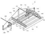
도 1은 본 발명의 바람직한 실시예에 따른 침목 교환장치가 레일 상에 설치된 모습을 도시한 사시도이다.
도2는 본 발명의 바람직한 실시예에 따른 침목 교환장치의 바디부와, 외측주행부와 하중분산부의 분해사시도이다.
도3은 본 발명의 바람직한 실시예에 따른 침목 교환장치의 좌우이동부를 도시한 사시도이다.
도4는 본 발명의 바람직한 실시예에 따른 침목 교환장치의 좌우이동부와 지렛대부의 분해사시도이다
도 5는 본 발명의 바람직한 실시예에 따른 침목 교환장치의 부상방지부의 사시도이다.
도 6은 본 발명의 바람직한 실시예에 따른 침목 교환장치의 부상방지부의 정면도이다.
도 7은 본 발명의 바람직한 실시예에 따른 침목 교환장치의 각부 구성이 바디부에 수용된 모습을 도시한 사시도이다.1 is a perspective view showing a sleeper exchange device installed on a rail according to a preferred embodiment of the present invention.
Figure 2 is an exploded perspective view of the body portion, the outer running portion and the load distribution of the sleeper exchange apparatus according to a preferred embodiment of the present invention.
Figure 3 is a perspective view showing the left and right moving parts of the sleeper exchange apparatus according to a preferred embodiment of the present invention.
Figure 4 is an exploded perspective view of the left and right moving portion and the lever of the sleeper exchange apparatus according to a preferred embodiment of the present invention
5 is a perspective view of the injury prevention part of the sleeper exchange apparatus according to a preferred embodiment of the present invention.
Figure 6 is a front view of the injury prevention portion of the sleeper exchange apparatus according to a preferred embodiment of the present invention.
7 is a perspective view showing a state in which the body parts of the sleeper exchange apparatus according to the preferred embodiment of the present invention is accommodated in the body portion.
본 발명의 설명에 앞서, 레일의 형성방향을 전후방향으로, 한 쌍의 레일이 이루는 궤간 방향을 좌우방향으로, 지면에 대해 연작한 방향을 상하방향으로 정의하기로 한다.Prior to the description of the present invention, the direction in which the rail is formed is defined in the front-rear direction, the gap direction formed by the pair of rails is defined in the left-right direction, and the direction that is softened with respect to the ground is defined in the vertical direction.
이하, 상기와 같은 본 발명의 일실시예에 대하여 도면을 참조하여 상세히 설명한다.Hereinafter, an embodiment of the present invention as described above will be described in detail with reference to the accompanying drawings.
도 1에 도시된 바와 같이, 침목(30)은 레일(20)의 설치방향을 따라 일정한 간격을 두고 다수개 설치되어, 그 상면에 설치된 레일(20)의 하중을 분산하고, 레일(20)의 위치를 고정하는 역할을 한다.As shown in FIG. 1, a plurality of
본 발명은 다수의 침목(30) 중 일부가 손상될 시 해당 침목(30)을 안전하고 손쉽게 교체하기 위한 장치이다.The present invention is a device for safely and easily replacing the
본 발명의 바람직한 실시예에 따른 침목 교환장치(10)는 크게 몸체부(100), 외측주행부(200), 좌우이동부(300), 지렛대부(400), 하중분산부(500) 및 부상방지부(600)를 포함한다.
몸체부(100)는 침목(30)을 레일(20)을 따라 이송할 수 있도록 하며, 각부 구성이 설치되는 부분이다.The
도 2에 도시된 바와 같이, 몸체부(100)는 상기 한 쌍의 레일(20) 상에 거치되도록 배치되는 몸체 플레이트(110)와, 상기 몸체 플레이트(110)가 레일(20)을 따라 이송될 수 있도록 몸체 플레이트(110) 하면의 각 레일(20)과 접하는 지점에 설치되는 레일바퀴(170)로 구성된다.As shown in FIG. 2, the
참고로 상기 레일바퀴(170)는 레일(20)로부터 몸체부(100)가 이탈되지 않도록 중앙이 상기 레일(20) 상면 형상에 따라 오목하게 형성된 이륜항가 형태인 것이 바람직하다.For reference, the
한편, 몸체 플레이트(110)는 레일(20) 상에 거치될 시 상기 몸체 플레이트(110) 상면에는 궤간 방향으로 길게 형성되는 제1 이송레일(111)과, 오목하게 함몰되어 형성되는 보관공간(112)이 형성된다.On the other hand, when the
상기 제1 이송레일(111)은 좌우이동부(300)가 설치되어 슬라이딩되는 공간이며, 보관공간(112)은 본 발명의 바람직한 실시예에 따른 침목 교환장치(10)의 각부구성이 몸체부(100)로부터 분해되어 수용되기 위한 공간이다.The
도 2에서는 공간효율을 위해 제1 이송레일(111)의 측면이 보관공간(112)을 형성하는 벽면에 포함된 것으로 도시하였다. 이 경우, 보관공간(112)을 이루고 있는 보관공간(112) 하면이 상기 제1 이송레일(111)에 결합될 좌우이동부(300)의 주행을 방해하지 않도록 제1 이송레일(111)과 소정간격 이격되어 형성하는 것이 바람직하다. 즉, 보관공간(112)의 하면은 상기 제1 이송레일(111)의 대향면 벽면으로부터 수평방향으로 연장형성 될 뿐 상기 제1 이송레일(111)과는 이어지지 않도록 'ㄴ'자 형태로 형성됨이 바람직 할 것이다.In FIG. 2, the side surfaces of the
한편, 상기 몸체 플레이트(110)는 각부 구성이 결합되기 위한 돌기들이 형성되는데, 상기 몸체 플레이트(110)의 상면 일측에는 하중분산봉 결합돌기(130)가 상측으로 길게 형성되며, 몸체 플레이트(110)가 레일(20)상에 거치되었을 시를 기준으로 몸체 플레이트(110) 일측면에는 외측주행부 결합돌기(150)가 궤간 외측방향으로 길게 연장되어 형성되고, 상기 몸체 플레이트(110)의 일측부 또는 타측부의 레일(20) 상측에 위치되는 부위에는 전방측면 또는 후방측면으로부터 부상방지부 결합돌기(190)가 전후방향으로 연장 형성된다.On the other hand, the
참고로, 도 2에는 부상방지부 결합돌기(190)를 몸체 플레이트(110) 타측에 형성된 것으로 도시하였다.For reference, FIG. 2 shows that the anti-floating
외측주행부(200)는 침목 교체작업 시 교체가 필요한 침목을 궤간 외측으로 이송시키기 위한 구성인 좌우이동부(300)의 이동경로를 제공하는 역할을 한다.The
외측주행부(200)는 좌우로 길게 형성된 기둥 형상으로, 일단은 중실 기둥 형상또는 중공형상 등 어떤 형태로든 무관하나, 타단부는 중공형상으로 형성되어 상기 외측주행부 결합돌기(150)에 끼움결합 될 수 있도록 형성된다.The outer running
상기 외측주행부(200)는 상단에 상기 제1 이송레일(111)과 마찬가지로, 후술할 좌우이동부(300)가 슬라이딩 가능하게 형성된 제2 이송레일(20)이 형성된다. 이때, 상기 제2 이송레일(210)은 외측주행부 상에 별도의 제2 이송레일(210)이 더 형성되거나, 도시된 바와 같이 외측주행부(200) 자체가 제2 이송레일(210)인 것으로 형성 될 수 있다.Like the first conveying
하중분산부(500)는 궤간 외측으로 돌출되게 형성된 외측주행부(200)에 하중이 집중 될 시 몸체부(100)가 레일(20)로부터 이탈되는 등의 안전문제 발생을 예방하고자, 외측주행부(200)의 하중을 몸체부(100)측으로 적절히 분산시키기 위한 구성이다.The
하중분산부(500)는 제1내지 3 하중분산봉(510, 530, 550)과, 와이어(570)를 포함하는데, 제1 하중분산봉(510)은 상하로 길게 연장 형성된 기둥형상이며 그 하단부가 중공형태로 형성되어 상기 몸체부(100)의 하중분산봉 결합돌기(130)에 끼움 결합된다.The
그리고 제1 하중분산봉(510) 상단에는 중앙에 홈이 파여진 휠(511)이 설치되어 후술할 와이어(570)가 안착된다.The
제2 하중분산봉(530)은 상기 몸체부(100)의 타단 상면으로부터 상측으로 길게 연장 형성되며, 그 상단에는 상기 와이어(570)의 구속을 위한 홀이 형성된다.The second
제3 하중분산봉(550)은 외측주행부(200)의 일단에 상기 제2 하중분산봉과 동일한 형태로 기립되어 형성되며, 제2 하중분산봉(530)과 제3 하중분산봉(550)은 제1 하중분산봉(510)보다 그 길이가 짧게 형성된다.The third
와이어(570)는 일단이 상기 제3 하중분산봉(550) 상단의 홀을 통하여 제3 하중분산봉(550)에 구속되고, 중앙부는 상술한 바와 같이 제1 하중분산봉(510) 상단의 휠(511)에 안착되며, 타단은 제2 하중분산봉(530) 상단의 홀을 통해 구속된다.One end of the
즉, 하중분산부(500)의 상술한 바와 같은 구조는 마치 사장교와 유사한 형태를 취하여 외측주행부(200)에 하중이 집중될 시 상기 제3 하중분산봉(550)과 와이어(570)를 통해 제1 하중분산봉(510) 및 제2 하중분산봉(530)으로 분산시켜 하중 쏠림현상을 해소하는 것이다.That is, the structure as described above of the
참고로, 상기 제2 하중분산봉(530)과 제3 하중분산봉(550)이 상측으로 길게 형성된 이유는 제2 하중분산봉(530)과 제3 하중분산봉(550)의 상단에 구속된 와이어(570)가 후술할 좌우이동부(300)의 이동에 방해가 되지 않도록 하기 위함이다.For reference, the reason why the second
도 3에 도시된 바와 같이, 좌우이동부(300)는 제1 이송레일(111) 또는 제2 이송레일(210) 상에 슬라이딩 가능하게 각각 하나 이상이 설치되어, 지렛대부(400)를 통해 인양된 침목을 좌우방향으로 이송시키는 역할을 하며, 좌우이동몸체(310)와 좌우이동롤러(330)로 구성된다.As shown in FIG. 3, the left and right moving
상기 좌우이동몸체(310)는 제1 이송레일(111) 또는 제2 이송레일(210)의 일부 또는 전부를 감싸도록 형성되는데, 상기 제1 이송레일(111) 또는 제2 이송레일(210)로부터 이탈되지 않도록 하는 형상이라면 어떤 형태이든 무방하다.The left and right moving
좌우이동롤러(330)는 좌우이동부가 제1 이송레일(111) 또는 제2 이송레일(210) 상면을 좀 더 원활하게 슬라이딩 하도록 한다.The left and right moving
좌우이동롤러(330)는 좌우이동몸체(310)와 제1 이송레일(111) 또는 제2 이송레일(210)이 접촉하는 부위에 설치되어, 제1 이송레일(111) 또는 제2 이송레일(210) 상면 따라 구름으로써, 좌우이동몸체(310)와 제1 이송레일(111) 또는 제2 이송레일 사이의 마찰력을 저감시키는 것이다.The left and right moving
한편, 지렛대부(400)는 좌우이동몸체(310) 상단에 설치되어, 침목(30)을 인양하는 역할을 한다.On the other hand, the
지렛대부(400)는 도 4에 도시된 바와 같이, 지렛대 축(410)과, 지렛대(430)와, 후크(450)를 포함하여 구성된다.As shown in FIG. 4, the
상기 지렛대 축(410)은 봉형태로 좌우이동몸체(310) 상단에 기립된 형상으로 형성되되, 그 상단은 중공형태로 형성된다.The
덧붙여, 지렛대 축(410)은 도시된 바와 같이 단일 개체로 형성될 수도 있고, 좌우이동몸체(310) 상단에 중실봉의 형태로 소정 높이 돌출되어 형성되는 하부 지렛대축과, 하부 지렛대축 상단부에 높이조절 가능하게 결합되는 상부 지렛대축으로 구성될 수도 있을 것이다.In addition, the
지렛대(430)의 형상은 길게 형성된 봉 형태이되, 중앙부에는 지렛대(430)가 지렛대 축(410)과 결합 되도록 하는 결합부재(431)가 힌지결합 된 형태이다.The shape of the
상기 결합부재(431)의 형태에 대하여 좀 더 구체적으로 살펴보면, 상기 결합부재(431)는 소정 길이를 가지는 봉 형태이며, 상단이 상기 지렛대(430)의 중앙부와 상하방향으로 회동 가능하도록 힌지 결합되고, 하단에는 베어링(432)이 설치된 형태이다. 이때, 상기 베어링(432)의 외경은 상기 지렛대 축(410) 상단의 내경과 동일하게 형성되어 지렛대 축(410) 상단에 끼움 결합된다.Looking at the shape of the coupling member 431 in more detail, the coupling member 431 is a rod shape having a predetermined length, the upper end is hinged to be able to rotate in the vertical direction with the central portion of the
즉, 지렛대부(400)는 상기 결합부재(431)를 통하여 지렛대 축(410)의 상단을 중심으로 상하 및 좌우로 회동가능하게 결합되는 것이다.That is, the
한편, 후크(450)는 지렛대(430)는 일단에 마련되는데, 상기 후크(450)에는 인양고리(451)가 연결된다.On the other hand, the
인양고리(451)는 길게 형성된 것으로 상단은 상기 후크(450)에 걸려질 수 있도록 환형의 고리가 형성되고, 하단은 침목(30)의 체결구를 걸 수 있도록 갈고리 형태로 형성된다.The
참고로, 상기 인양고리(451)는 다양한 길이로 형성되어 인양하고자하는 침목(30)의 위치에 따라 교체하여 사용할 수 있도록 한다.For reference, the
부상방지부(600)는 도 5 및 도 6에 도시된 바와 같이, 몸체부(100)의 부상방지부 결합돌기(190)에 탈착가능하게 결합되며, 몸체부(100)를 레일(20)에 고정하여 본 발명의 바람직한 발명에 따른 침목 교환장치(10)가 레일(20)로부터 이탈되는 것을 방지하는 역할을 한다.As shown in FIGS. 5 and 6, the
이러한 부상방지부(600)는 홀딩플레이트(610)와, 홀딩날개(630)와, 홀딩롤러(650) 및 조임부재(670)로 구성된다.The
홀딩플레이트(610)는 상기 부상방지부 결합돌기(190) 하면에 접하도록 배치되며, 홀딩플레이트(610) 및 부상방지부 결합돌기(190)에는 수직방향으로 연결홀(611)이 형성되어 상기 연결홀(611)에 핀을 끼움으로써 부상방지부(600)가 몸체부(100)에 고정된다.The holding
홀딩플레이트(610) 양단 각각에는 홀딩날개(630)가 힌지결합 되어 홀딩플레이트(610)가 부상방지부 결합돌기(190)에 결합될 시, 홀딩플레이트(610) 일단에 결합된 홀딩날개(630)는 레일(20)의 궤간 측 측면에, 홀딩플레이트(610) 타단에 결합된 홀딩날개(630)는 레일(20)의 궤간 외측 측면에 위치하게 된다.Both ends of the holding
이때, 각 홀딩날개(630)의 단부는 레일(20)의 하부의 오목하게 형성된 부위에 위치할 정도로 길게 형성되고, 각각의 홀딩날개(630) 단부에는 홀딩롤러(650)가 레일(20) 하단부의 오목하게 형성된 하면을 따라 구를 수 있도록 설치된다.At this time, the end of each holding
한편, 상기 홀딩날개(630)에는 홀딩플레이트(610)가 부상방지부 결합돌기(190)에 안착될 시 상기 한 쌍의 홀딩날개(630)를 수평방향으로 관통하도록 형성된 조임부재 결합홀(631)이 형성된다.Meanwhile, the
조임부재(670)는 나사(671)와 볼트(673)로 실시될 수 있는데, 상기 각 홀딩날개(630)에 형성된 조임부재 결합홀(631)에 나사(671)가 수평방향으로 관통되도록 설치하고, 나사(671)의 단부를 상기 볼트(673)로 조여짐으로써 상기 한 쌍의 홀딩날개(630) 사이 거리가 좁혀져 몸체부(100)가 레일(20)에 단단히 고정되는 것 이다.Tightening
여기서 상기 조임부재(670)의 조임 정도에 따라 상기 몸체부(100)가 레일(20)에 완전히 구속될 수도 있고, 몸체부(100)가 레일(20)을 따라 전후방향으로 슬라이딩 가능하면서도 레일(20)에 이탈하지는 못하도록 고정될 수도 있다.Here, the
이하에서는 상기와 같이 구성된 본 발명의 작용에 대하여 도면을 참조하여 설명한다.Hereinafter will be described with reference to the drawings the operation of the present invention configured as described above.
본 발명의 바람직한 실시예에 따른 침목 교환장치(10)는 도 7에 도시된 바와 같이, 몸체부(100)의 보관공간(112) 내에 각부 구성들이 수용된 형태로 마련되며, 침목 교체작업이 필요할 시 도 1에 도시된 바와 같이 몸체 플레이트(110)는 레일바퀴(170)가 레일(20) 상면에 안착되도록 몸체 플레이트를 한 쌍의 레일(20) 상에 거치된다.
다음, 보관공간(112) 내에 수용되어 있던 부상방지부(600)는 부상방지부 결합돌기(190)에 핀을 통해 결합되며, 조임부재(670)를 통해 몸체부(100)가 레일(20)로부터 이탈되지 않도록 고정 된다.Next, the
마찬가지로, 보관공간(112) 내에 수용되어 있던 외측주행부(200) 또한 외측 주행부 결합돌기(150)에 끼움 결합되고, 제1 하중분산봉(510)은 하중분산봉 결합돌기(130) 상단에 끼움 결합된다.Similarly, the outer running
이어, 와이어(570) 일단이 제3 하중분산봉(550) 상단에 고정되고, 중앙부가 제1 하중분산봉(510) 상단에 마련된 휠(511)에 안착되며, 타단이 제2 하중분산봉(530) 상단에 고정되면 침목(30) 교체를 위한 침목 교환장치(10)의 준비가 완료된다.Then, one end of the
다음, 교체할 대상 침목(30)의 양단부에 마련된 체결구에 외측주행부(200) 상에 마련된 좌우이동부(300)와 몸체부(100) 상에 마련된 외측주행부(200) 각각의 인양고리(451)가 걸리고, 상기 교체 대상 침목(30)이 지렛대부(400)에 의해 인양된 상태에서 한 쌍의 좌우이동부(300)가 일측으로 슬라이딩 되면 상기 교체 대상 침목(30)은 궤간 외측으로 이탈되는 것이다. 이후 새로운 침목(30)을 교체 대상 침목(30)이 있던 자리에 상술한 과정을 역순으로 하여 교체할 수 있다.Next, the lifting hooks of the left and right moving
본 발명의 상기한 실시 예에 한정하여 기술적 사상을 해석해서는 안 된다. 적용범위가 다양함은 물론이고, 청구범위에서 청구하는 본 발명의 요지를 벗어남이 없이 당업자의 수준에서 다양한 변형 실시가 가능하다. 따라서 이러한 개량 및 변경은 당업자에게 자명한 것인 한 본 발명의 보호범위에 속하게 된다.The technical spirit should not be interpreted as being limited to the above embodiments of the present invention. Various modifications may be made at the level of those skilled in the art without departing from the spirit of the invention as claimed in the claims. Therefore, such improvements and modifications fall within the protection scope of the present invention, as will be apparent to those skilled in the art.
10: 침목 교환장치
20: 레일
30: 침목
100: 몸체부
110: 몸체 플레이트
111: 제1 이송레일
112: 보관공간
130: 하중분산봉 결합돌기
150: 외측 주행부 결합돌기
170: 레일바퀴
190: 부상방지부 결합돌기
200: 외측주행부
210: 제2 이송레일
300: 좌우이동부
310: 좌우이동몸체
330: 좌우이동롤러
400: 지렛대부
410: 지렛대 축
430: 지렛대
431: 결합부재
432: 베어링
450: 후크
451: 인양고리
500: 하중분산부
510: 제1 하중분산봉
511: 휠
530: 제2 하중분산봉
550: 제3 하중분산봉
570: 와이어
600: 부상방지부
610: 홀딩플레이트
611: 연결홀
630: 홀딩날개
631: 조임부재 결합홀
650: 홀딩롤러
670: 조임부재
671: 나사
673: 볼트10: sleeper exchange device
20: rail
30: sleeper
100: body
110: body plate
111: first transfer rail
112: storage space
130: load distribution rod coupling protrusion
150: engaging projection outside the running portion
170: rail wheel
190: engaging protrusions
200: outer running part
210: second conveying rail
300: left and right moving parts
310: left and right moving body
330: horizontal roller
400: leverage
410: lever axis
430: lever
431: coupling member
432: bearing
450: hook
451: lifting hook
500: load distribution unit
510: first load distribution rod
511: wheel
530: second load distribution rod
550: third load distribution rod
570: wire
600: injury prevention unit
610: holding plate
611: connecting hole
630: holding wing
631: fastening member coupling hole
650: holding roller
670: tightening member
671: screw
673: Bolt
Claims (11)
Translated fromKorean한 쌍의 상기 레일 상에 거치되어 레일을 따라 이송가능하게 설치되는 몸체부;
상기 몸체부와 결합되며 한쌍의 상기 레일 좌우방향 외측으로 길게 형성된 외측주행부;
상기 몸체부 및 외측주행부상에 슬라이딩 가능하게 설치되는 좌우이동부;
상기 좌우이동부 상에 설치되며, 침목을 걸어 인양하는 지렛대부; 및
상기 외측주행부의 일단부와 상기 몸체부의 타단부를 서로 연결하도록 형성되어 상기 외측주행부에 부가되는 하중을 상기 몸체부로 분산시키는 하중분산부;를 포함하는 것을 특징으로 하는 침목 교환장치.
As to replace the sleeper supporting the rail of the railroad,
A body part mounted on the pair of rails to be transportably installed along the rails;
An outer traveling part coupled to the body part and formed to extend in a pair of the rails in a horizontal direction;
Left and right moving parts that are slidably installed on the body portion and the outer running portion;
A lever unit installed on the left and right moving parts and lifting a sleeper; And
And a load distribution unit configured to connect one end of the outer running part and the other end of the body part to each other to distribute the load added to the outer running part to the body part.
상기 하중분산부는,
상기 몸체부의 외측주행부측 단부에 기립된 형태로 형성되는 제1 하중분산봉과, 상기 외측주행부의 일단과 상기 제1 하중분산봉과, 상기 몸체부 타단을 서로 연결하는 와이어를 포함하는 것을 특징으로 하는 침목 교환장치.
The method of claim 2,
The load distribution unit,
A sleeper comprising: a first load dispersing rod formed in a form standing up at an end portion of the outer running portion of the body portion, a wire connecting one end of the outer traveling portion, the first load distributing rod, and the other end of the body portion to each other; Exchange device.
상기 하중분산부는,
상기 몸체부의 상기 제1 하중분산봉이 형성된 타단에 형성되는 제2 하중분산봉과, 상기 외측주행부 일단에 기립된 형태로 형성되는 제3 하중분산봉이 더 형성되며, 상기 와이어는 상기 제1내지 제3하중분산봉의 상단을 서로 연결하도록 설치된 것을 특징으로 하는 침목 교환장치.
The method of claim 3,
The load distribution unit,
A second load distribution rod is formed on the other end formed with the first load distribution rod formed in the body portion, and a third load distribution rod formed in the form standing up on one end of the outer running portion, the wire is the first to third Sleeper exchange device, characterized in that installed to connect the top of the load balancing rods to each other.
상기 제1 하중분산봉은 제2 내지 제3하중분산봉 보다 길게 형성된 것을 특징으로 하는 침목 교환장치.
The method of claim 4, wherein
The first load dispersing rod is a sleeper exchange device, characterized in that formed longer than the second to third load dispersing rod.
상기 몸체부는,
상기 한 쌍의 레일 상에 거치되며, 상면에 제1 이송레일이 형성된 몸체 플레이트와, 상기 몸체 플레이트와 상기 레일 사이에 설치되는 레일바퀴를 포함하고,
상기 외측 주행부는,
상기 몸체부 상면에 제2 이송레일이 형성되고,
상기 좌우이동부는,
상기 제1 이송레일 또는 제2 이송레일로부터 이탈되지 않도록 형성된 좌우이동몸체를 포함하는 것을 특징으로 하는 침목 교환장치.
The method of claim 2,
The body portion,
It is mounted on the pair of rails, and includes a body plate having a first transfer rail formed on the upper surface, and a rail wheel installed between the body plate and the rail,
The outer running portion,
A second conveyance rail is formed on the upper surface of the body portion,
The left and right moving parts,
Sleeping apparatus including a left and right moving body formed so as not to be separated from the first conveying rail or the second conveying rail.
한 쌍의 상기 레일 상에 거치되어 레일을 따라 이송가능하게 설치되는 몸체부;
상기 몸체부와 결합되며 한쌍의 상기 레일 좌우방향 외측으로 길게 형성된 외측주행부; 및
상기 몸체부 및 외측주행부상에 슬라이딩 가능하게 설치되는 좌우이동부;
상기 좌우이동부 상에 설치되며, 침목을 걸어 인양하는 지렛대부;를 포함하며,
상기 지렛대부는,
상기 좌우이동부 상에 기립된 형태로 형성되는 지렛대 축과, 길게 형성되며, 중앙부가 상기 지렛대 축 상단에 상하 및 좌우로 회동가능하게 결합되는 지렛대와, 상기 지렛대 일단에 연결되며, 상기 침목의 체결구가 걸려지는 후크를 포함하는 것을 특징으로 하는 침목 교환장치.
As to replace the sleeper supporting the rail of the railroad,
A body part mounted on the pair of rails to be transportably installed along the rails;
An outer traveling part coupled to the body part and formed to extend in a pair of the rails in a horizontal direction; And
Left and right moving parts that are slidably installed on the body portion and the outer running portion;
It is installed on the left and right moving portion, the lever to lift the sleeper to lift; includes;
The lever loan,
The lever shaft is formed in the form standing on the left and right moving portion, and the elongated, the center portion is connected to the upper and lower sides and the left and right pivotally coupled to the lever shaft, and connected to one end of the lever, the fastener of the sleeper Sleeper exchange device characterized in that it comprises a hook to be caught.
상기 침목 교환장치는,
상기 몸체부에 결합되며, 상기 몸체부를 상기 레일에 고정시키는 부상방지부;를 더 포함하는 것을 특징으로 하는 침목 교환장치.
The method of claim 2,
The sleeper exchange device,
The sleeper exchange apparatus is coupled to the body portion, further comprising; an injury prevention portion for fixing the body portion to the rail.
상기 부상방지부는,
상기 레일의 궤간 내측면과 외측면을 감싸도록 형성된 클램프 구조의 홀딩부재와, 상기 홀딩부재 양단에 상기 홀딩부재 양단 사이거리를 조절하는 조임부재를 포함하는 것을 특징으로 하는 침목 교환장치.
The method of claim 8,
The injury prevention part,
And a clamping member holding a clamp structure formed to surround the gap inner and outer surfaces of the rail, and a fastening member configured to adjust a distance between both ends of the holding member at both ends of the holding member.
상기 외측주행부와 지렛대부와 하중분산부와 부상방지부는 서로 분해 가능하게 결합된 것을 특징으로 하는 침목 교환장치.
The method of claim 8,
The sleeper exchange apparatus, characterized in that the outer running portion, the lever portion, the load distribution portion and the anti-floating portion is decomposable to each other.
상기 몸체부는 일측에 보관공간이 형성되어,
상기 분해된 외측주행부와, 지렛대부와, 하중분산부와, 부상방지부를 보관 가능한 것을 특징으로 하는 침목 교환장치.The method of claim 10,
The body portion is formed with a storage space on one side,
Sleeper exchange device characterized in that the disassembled outer running portion, lever lever portion, load distribution portion, and anti-floating portion can be stored.
Priority Applications (1)
| Application Number | Priority Date | Filing Date | Title |
|---|---|---|---|
| KR1020180035675AKR102087418B1 (en) | 2018-03-28 | 2018-03-28 | Exchange Decice For Sleeper |
Applications Claiming Priority (1)
| Application Number | Priority Date | Filing Date | Title |
|---|---|---|---|
| KR1020180035675AKR102087418B1 (en) | 2018-03-28 | 2018-03-28 | Exchange Decice For Sleeper |
Publications (2)
| Publication Number | Publication Date |
|---|---|
| KR20190113247A KR20190113247A (en) | 2019-10-08 |
| KR102087418B1true KR102087418B1 (en) | 2020-03-10 |
Family
ID=68208545
Family Applications (1)
| Application Number | Title | Priority Date | Filing Date |
|---|---|---|---|
| KR1020180035675AActiveKR102087418B1 (en) | 2018-03-28 | 2018-03-28 | Exchange Decice For Sleeper |
Country Status (1)
| Country | Link |
|---|---|
| KR (1) | KR102087418B1 (en) |
Families Citing this family (2)
| Publication number | Priority date | Publication date | Assignee | Title |
|---|---|---|---|---|
| CN113152174B (en)* | 2021-01-22 | 2024-10-22 | 北京国兴力德新材料技术有限公司 | Method and device for efficiently replacing railway line sleeper |
| CN120556324B (en)* | 2025-07-31 | 2025-09-30 | 四川省铁路建设有限公司 | Sleeper replacement device |
Family Cites Families (2)
| Publication number | Priority date | Publication date | Assignee | Title |
|---|---|---|---|---|
| JPS5155510U (en)* | 1974-10-23 | 1976-04-28 | ||
| KR200483472Y1 (en) | 2015-12-28 | 2017-05-18 | 주식회사 비티에스엘이디 | Sleeper Removing Apparatus for Concrete Ballast |
- 2018
- 2018-03-28KRKR1020180035675Apatent/KR102087418B1/enactiveActive
Also Published As
| Publication number | Publication date |
|---|---|
| KR20190113247A (en) | 2019-10-08 |
Similar Documents
| Publication | Publication Date | Title |
|---|---|---|
| KR102111100B1 (en) | Method for transport this Concrete mold using Support Elevated Concrete mold Carrier | |
| US9004509B2 (en) | Transport cart with tilting load carrier | |
| KR102087418B1 (en) | Exchange Decice For Sleeper | |
| CN102367651A (en) | U-shaped concrete beam bridge girder erection machine | |
| JP6391145B2 (en) | Foldable fence | |
| EP0001341B1 (en) | Improvements in girder roller fittings | |
| CN109573829B (en) | Self-balancing compensation heavy hydraulic lifting beam of monorail crane | |
| US20050028704A1 (en) | Material handling system enclosed track arrangement | |
| US4105219A (en) | Positive locking device for boat trailer bolster bracket | |
| CN210195811U (en) | Underground single hydraulic prop carrying device | |
| US7624843B2 (en) | Multiple task working platform | |
| CN215709149U (en) | Simple and convenient short-distance conveying device for reinforcing steel bars | |
| JP6931441B2 (en) | Mobile home | |
| CN206217933U (en) | One kind sliding positioning precast stair section transfer car(buggy) | |
| CN214989897U (en) | Shipping tooling | |
| US6848880B2 (en) | Cargo rack | |
| JP7407650B2 (en) | Transportation equipment and transportation method | |
| US1773030A (en) | Tubular steel tower | |
| US20050117999A1 (en) | Method and apparatus for truss rollout | |
| JPH0439868Y2 (en) | ||
| US4406098A (en) | Drilling ramp | |
| KR102250236B1 (en) | Prefabricated Plate Transfer Cart | |
| CN209972487U (en) | Interval cable laying and transporting device for subway tunnel | |
| KR102529305B1 (en) | Worker support scaffold of specially equipped vehicle | |
| US687860A (en) | Log-carrier. |
Legal Events
| Date | Code | Title | Description |
|---|---|---|---|
| A201 | Request for examination | ||
| PA0109 | Patent application | Patent event code:PA01091R01D Comment text:Patent Application Patent event date:20180328 | |
| PA0201 | Request for examination | ||
| E902 | Notification of reason for refusal | ||
| PE0902 | Notice of grounds for rejection | Comment text:Notification of reason for refusal Patent event date:20190927 Patent event code:PE09021S01D | |
| PG1501 | Laying open of application | ||
| E701 | Decision to grant or registration of patent right | ||
| PE0701 | Decision of registration | Patent event code:PE07011S01D Comment text:Decision to Grant Registration Patent event date:20200303 | |
| GRNT | Written decision to grant | ||
| PR0701 | Registration of establishment | Comment text:Registration of Establishment Patent event date:20200304 Patent event code:PR07011E01D | |
| PR1002 | Payment of registration fee | Payment date:20200305 End annual number:3 Start annual number:1 | |
| PG1601 | Publication of registration | ||
| PR1001 | Payment of annual fee | Payment date:20230306 Start annual number:4 End annual number:4 | |
| PR1001 | Payment of annual fee | Payment date:20240304 Start annual number:5 End annual number:5 | |
| PR1001 | Payment of annual fee | Payment date:20250304 Start annual number:6 End annual number:6 |