KR102084060B1 - Manufacuring mehtod of protective window and display device produced by using the same - Google Patents
Manufacuring mehtod of protective window and display device produced by using the sameDownload PDFInfo
- Publication number
- KR102084060B1 KR102084060B1KR1020130071847AKR20130071847AKR102084060B1KR 102084060 B1KR102084060 B1KR 102084060B1KR 1020130071847 AKR1020130071847 AKR 1020130071847AKR 20130071847 AKR20130071847 AKR 20130071847AKR 102084060 B1KR102084060 B1KR 102084060B1
- Authority
- KR
- South Korea
- Prior art keywords
- film
- transparent member
- protective window
- window
- high hardness
- Prior art date
- Legal status (The legal status is an assumption and is not a legal conclusion. Google has not performed a legal analysis and makes no representation as to the accuracy of the status listed.)
- Active
Links
- 230000001681protective effectEffects0.000titleclaimsdescription48
- -1polyethylene phthalatePolymers0.000claimsabstractdescription12
- 238000000034methodMethods0.000claimsabstractdescription9
- 239000004417polycarbonateSubstances0.000claimsabstractdescription8
- 229920000515polycarbonatePolymers0.000claimsabstractdescription8
- 238000002347injectionMethods0.000claimsabstractdescription7
- 239000007924injectionSubstances0.000claimsabstractdescription7
- 229920003207poly(ethylene-2,6-naphthalate)Polymers0.000claimsabstractdescription7
- 239000011112polyethylene naphthalateSubstances0.000claimsabstractdescription7
- 238000004519manufacturing processMethods0.000claimsdescription12
- 229920000139polyethylene terephthalatePolymers0.000claimsdescription6
- 239000005020polyethylene terephthalateSubstances0.000claimsdescription6
- 238000010438heat treatmentMethods0.000claimsdescription5
- 239000011247coating layerSubstances0.000claimsdescription4
- 239000010408filmSubstances0.000description72
- 239000000758substrateSubstances0.000description12
- 239000010410layerSubstances0.000description10
- 239000011347resinSubstances0.000description8
- 229920005989resinPolymers0.000description8
- 239000000463materialSubstances0.000description7
- 239000002313adhesive filmSubstances0.000description5
- 238000000465mouldingMethods0.000description5
- 238000007639printingMethods0.000description5
- 239000010409thin filmSubstances0.000description5
- XECAHXYUAAWDEL-UHFFFAOYSA-Nacrylonitrile butadiene styreneChemical compoundC=CC=C.C=CC#N.C=CC1=CC=CC=C1XECAHXYUAAWDEL-UHFFFAOYSA-N0.000description3
- 239000004676acrylonitrile butadiene styreneSubstances0.000description3
- 229920000122acrylonitrile butadiene styrenePolymers0.000description3
- 239000000853adhesiveSubstances0.000description3
- 230000001070adhesive effectEffects0.000description3
- 229920003229poly(methyl methacrylate)Polymers0.000description3
- 239000004926polymethyl methacrylateSubstances0.000description3
- 239000011230binding agentSubstances0.000description2
- 239000004973liquid crystal related substanceSubstances0.000description2
- 239000011159matrix materialSubstances0.000description2
- 238000006116polymerization reactionMethods0.000description2
- 239000005341toughened glassSubstances0.000description2
- 239000004698PolyethyleneSubstances0.000description1
- 239000003522acrylic cementSubstances0.000description1
- 239000012790adhesive layerSubstances0.000description1
- QVGXLLKOCUKJST-UHFFFAOYSA-Natomic oxygenChemical compound[O]QVGXLLKOCUKJST-UHFFFAOYSA-N0.000description1
- 238000002425crystallisationMethods0.000description1
- 230000008025crystallizationEffects0.000description1
- KPUWHANPEXNPJT-UHFFFAOYSA-NdisiloxaneChemical class[SiH3]O[SiH3]KPUWHANPEXNPJT-UHFFFAOYSA-N0.000description1
- UHPJWJRERDJHOJ-UHFFFAOYSA-Nethene;naphthalene-1-carboxylic acidChemical compoundC=C.C1=CC=C2C(C(=O)O)=CC=CC2=C1UHPJWJRERDJHOJ-UHFFFAOYSA-N0.000description1
- 230000007062hydrolysisEffects0.000description1
- 238000006460hydrolysis reactionMethods0.000description1
- 230000003301hydrolyzing effectEffects0.000description1
- 229910003471inorganic composite materialInorganic materials0.000description1
- 238000002156mixingMethods0.000description1
- 238000012986modificationMethods0.000description1
- 230000004048modificationEffects0.000description1
- 239000002105nanoparticleSubstances0.000description1
- 230000003287optical effectEffects0.000description1
- 229910052760oxygenInorganic materials0.000description1
- 239000001301oxygenSubstances0.000description1
- 238000007649pad printingMethods0.000description1
- 229920000642polymerPolymers0.000description1
- 239000002861polymer materialSubstances0.000description1
- 238000007650screen-printingMethods0.000description1
- 238000007789sealingMethods0.000description1
- 229920006268silicone filmPolymers0.000description1
- 239000007921spraySubstances0.000description1
- ZDHXKXAHOVTTAH-UHFFFAOYSA-NtrichlorosilaneChemical compoundCl[SiH](Cl)ClZDHXKXAHOVTTAH-UHFFFAOYSA-N0.000description1
- 239000005052trichlorosilaneSubstances0.000description1
- 238000007666vacuum formingMethods0.000description1
Images


Classifications
- H—ELECTRICITY
- H10—SEMICONDUCTOR DEVICES; ELECTRIC SOLID-STATE DEVICES NOT OTHERWISE PROVIDED FOR
- H10K—ORGANIC ELECTRIC SOLID-STATE DEVICES
- H10K59/00—Integrated devices, or assemblies of multiple devices, comprising at least one organic light-emitting element covered by group H10K50/00
- H10K59/40—OLEDs integrated with touch screens
- B—PERFORMING OPERATIONS; TRANSPORTING
- B29—WORKING OF PLASTICS; WORKING OF SUBSTANCES IN A PLASTIC STATE IN GENERAL
- B29C—SHAPING OR JOINING OF PLASTICS; SHAPING OF MATERIAL IN A PLASTIC STATE, NOT OTHERWISE PROVIDED FOR; AFTER-TREATMENT OF THE SHAPED PRODUCTS, e.g. REPAIRING
- B29C45/00—Injection moulding, i.e. forcing the required volume of moulding material through a nozzle into a closed mould; Apparatus therefor
- B29C45/16—Making multilayered or multicoloured articles
- B29C45/1679—Making multilayered or multicoloured articles applying surface layers onto injection-moulded substrates inside the mould cavity, e.g. in-mould coating [IMC]
- B—PERFORMING OPERATIONS; TRANSPORTING
- B29—WORKING OF PLASTICS; WORKING OF SUBSTANCES IN A PLASTIC STATE IN GENERAL
- B29C—SHAPING OR JOINING OF PLASTICS; SHAPING OF MATERIAL IN A PLASTIC STATE, NOT OTHERWISE PROVIDED FOR; AFTER-TREATMENT OF THE SHAPED PRODUCTS, e.g. REPAIRING
- B29C45/00—Injection moulding, i.e. forcing the required volume of moulding material through a nozzle into a closed mould; Apparatus therefor
- B29C45/14—Injection moulding, i.e. forcing the required volume of moulding material through a nozzle into a closed mould; Apparatus therefor incorporating preformed parts or layers, e.g. injection moulding around inserts or for coating articles
- B29C45/1418—Injection moulding, i.e. forcing the required volume of moulding material through a nozzle into a closed mould; Apparatus therefor incorporating preformed parts or layers, e.g. injection moulding around inserts or for coating articles the inserts being deformed or preformed, e.g. by the injection pressure
- B—PERFORMING OPERATIONS; TRANSPORTING
- B29—WORKING OF PLASTICS; WORKING OF SUBSTANCES IN A PLASTIC STATE IN GENERAL
- B29C—SHAPING OR JOINING OF PLASTICS; SHAPING OF MATERIAL IN A PLASTIC STATE, NOT OTHERWISE PROVIDED FOR; AFTER-TREATMENT OF THE SHAPED PRODUCTS, e.g. REPAIRING
- B29C45/00—Injection moulding, i.e. forcing the required volume of moulding material through a nozzle into a closed mould; Apparatus therefor
- B29C45/14—Injection moulding, i.e. forcing the required volume of moulding material through a nozzle into a closed mould; Apparatus therefor incorporating preformed parts or layers, e.g. injection moulding around inserts or for coating articles
- B29C45/14778—Injection moulding, i.e. forcing the required volume of moulding material through a nozzle into a closed mould; Apparatus therefor incorporating preformed parts or layers, e.g. injection moulding around inserts or for coating articles the article consisting of a material with particular properties, e.g. porous, brittle
- B29C45/14811—Multilayered articles
- B—PERFORMING OPERATIONS; TRANSPORTING
- B32—LAYERED PRODUCTS
- B32B—LAYERED PRODUCTS, i.e. PRODUCTS BUILT-UP OF STRATA OF FLAT OR NON-FLAT, e.g. CELLULAR OR HONEYCOMB, FORM
- B32B27/00—Layered products comprising a layer of synthetic resin
- B32B27/06—Layered products comprising a layer of synthetic resin as the main or only constituent of a layer, which is next to another layer of the same or of a different material
- B32B27/08—Layered products comprising a layer of synthetic resin as the main or only constituent of a layer, which is next to another layer of the same or of a different material of synthetic resin
- B—PERFORMING OPERATIONS; TRANSPORTING
- B32—LAYERED PRODUCTS
- B32B—LAYERED PRODUCTS, i.e. PRODUCTS BUILT-UP OF STRATA OF FLAT OR NON-FLAT, e.g. CELLULAR OR HONEYCOMB, FORM
- B32B37/00—Methods or apparatus for laminating, e.g. by curing or by ultrasonic bonding
- G—PHYSICS
- G09—EDUCATION; CRYPTOGRAPHY; DISPLAY; ADVERTISING; SEALS
- G09F—DISPLAYING; ADVERTISING; SIGNS; LABELS OR NAME-PLATES; SEALS
- G09F9/00—Indicating arrangements for variable information in which the information is built-up on a support by selection or combination of individual elements
- H—ELECTRICITY
- H10—SEMICONDUCTOR DEVICES; ELECTRIC SOLID-STATE DEVICES NOT OTHERWISE PROVIDED FOR
- H10K—ORGANIC ELECTRIC SOLID-STATE DEVICES
- H10K50/00—Organic light-emitting devices
- H10K50/80—Constructional details
- H10K50/84—Passivation; Containers; Encapsulations
- H10K50/844—Encapsulations
- H—ELECTRICITY
- H10—SEMICONDUCTOR DEVICES; ELECTRIC SOLID-STATE DEVICES NOT OTHERWISE PROVIDED FOR
- H10K—ORGANIC ELECTRIC SOLID-STATE DEVICES
- H10K50/00—Organic light-emitting devices
- H10K50/80—Constructional details
- H10K50/87—Arrangements for heating or cooling
- B—PERFORMING OPERATIONS; TRANSPORTING
- B29—WORKING OF PLASTICS; WORKING OF SUBSTANCES IN A PLASTIC STATE IN GENERAL
- B29K—INDEXING SCHEME ASSOCIATED WITH SUBCLASSES B29B, B29C OR B29D, RELATING TO MOULDING MATERIALS OR TO MATERIALS FOR MOULDS, REINFORCEMENTS, FILLERS OR PREFORMED PARTS, e.g. INSERTS
- B29K2623/00—Use of polyalkenes or derivatives thereof for preformed parts, e.g. for inserts
- B29K2623/04—Polymers of ethylene
- B29K2623/06—PE, i.e. polyethylene
- B—PERFORMING OPERATIONS; TRANSPORTING
- B29—WORKING OF PLASTICS; WORKING OF SUBSTANCES IN A PLASTIC STATE IN GENERAL
- B29K—INDEXING SCHEME ASSOCIATED WITH SUBCLASSES B29B, B29C OR B29D, RELATING TO MOULDING MATERIALS OR TO MATERIALS FOR MOULDS, REINFORCEMENTS, FILLERS OR PREFORMED PARTS, e.g. INSERTS
- B29K2633/00—Use of polymers of unsaturated acids or derivatives thereof for preformed parts, e.g. for inserts
- B29K2633/04—Polymers of esters
- B29K2633/12—Polymers of methacrylic acid esters, e.g. PMMA, i.e. polymethylmethacrylate
- B—PERFORMING OPERATIONS; TRANSPORTING
- B29—WORKING OF PLASTICS; WORKING OF SUBSTANCES IN A PLASTIC STATE IN GENERAL
- B29K—INDEXING SCHEME ASSOCIATED WITH SUBCLASSES B29B, B29C OR B29D, RELATING TO MOULDING MATERIALS OR TO MATERIALS FOR MOULDS, REINFORCEMENTS, FILLERS OR PREFORMED PARTS, e.g. INSERTS
- B29K2667/00—Use of polyesters or derivatives thereof for preformed parts, e.g. for inserts
- B29K2667/003—PET, i.e. poylethylene terephthalate
- B—PERFORMING OPERATIONS; TRANSPORTING
- B29—WORKING OF PLASTICS; WORKING OF SUBSTANCES IN A PLASTIC STATE IN GENERAL
- B29K—INDEXING SCHEME ASSOCIATED WITH SUBCLASSES B29B, B29C OR B29D, RELATING TO MOULDING MATERIALS OR TO MATERIALS FOR MOULDS, REINFORCEMENTS, FILLERS OR PREFORMED PARTS, e.g. INSERTS
- B29K2669/00—Use of PC, i.e. polycarbonates or derivatives thereof for preformed parts, e.g. for inserts
- B—PERFORMING OPERATIONS; TRANSPORTING
- B29—WORKING OF PLASTICS; WORKING OF SUBSTANCES IN A PLASTIC STATE IN GENERAL
- B29K—INDEXING SCHEME ASSOCIATED WITH SUBCLASSES B29B, B29C OR B29D, RELATING TO MOULDING MATERIALS OR TO MATERIALS FOR MOULDS, REINFORCEMENTS, FILLERS OR PREFORMED PARTS, e.g. INSERTS
- B29K2995/00—Properties of moulding materials, reinforcements, fillers, preformed parts or moulds
- B29K2995/0018—Properties of moulding materials, reinforcements, fillers, preformed parts or moulds having particular optical properties, e.g. fluorescent or phosphorescent
- B29K2995/002—Coloured
- B—PERFORMING OPERATIONS; TRANSPORTING
- B29—WORKING OF PLASTICS; WORKING OF SUBSTANCES IN A PLASTIC STATE IN GENERAL
- B29K—INDEXING SCHEME ASSOCIATED WITH SUBCLASSES B29B, B29C OR B29D, RELATING TO MOULDING MATERIALS OR TO MATERIALS FOR MOULDS, REINFORCEMENTS, FILLERS OR PREFORMED PARTS, e.g. INSERTS
- B29K2995/00—Properties of moulding materials, reinforcements, fillers, preformed parts or moulds
- B29K2995/0037—Other properties
- B29K2995/007—Hardness
- B—PERFORMING OPERATIONS; TRANSPORTING
- B29—WORKING OF PLASTICS; WORKING OF SUBSTANCES IN A PLASTIC STATE IN GENERAL
- B29L—INDEXING SCHEME ASSOCIATED WITH SUBCLASS B29C, RELATING TO PARTICULAR ARTICLES
- B29L2031/00—Other particular articles
- B29L2031/34—Electrical apparatus, e.g. sparking plugs or parts thereof
- B29L2031/3475—Displays, monitors, TV-sets, computer screens
Landscapes
- Engineering & Computer Science (AREA)
- Manufacturing & Machinery (AREA)
- Mechanical Engineering (AREA)
- Physics & Mathematics (AREA)
- Optics & Photonics (AREA)
- General Physics & Mathematics (AREA)
- Theoretical Computer Science (AREA)
- Devices For Indicating Variable Information By Combining Individual Elements (AREA)
- General Engineering & Computer Science (AREA)
Abstract
Translated fromKoreanDescription
Translated fromKorean본 발명은 보호용 윈도우의 제조 방법 및 이를 이용하여 제작한 표시 장치에 관한 것이다.The present invention relates to a method of manufacturing a protective window and a display device manufactured using the same.
최근, 휴대 전화, 내비게이션, 디지털 사진기, 전자 북, 휴대용 게임기, 또는 각종 단말기 등과 같이, 액정 표시 장치(Liquid Crystal Display, LCD)나 유기 전계 발광 표시 장치(Organic Light Emitting Diode, OLED)를 표시 패널로 포함하는 다양한 휴대용 전자 기기들이 사용되고 있다.Recently, liquid crystal displays (LCDs) and organic light emitting diodes (OLEDs) are used as display panels, such as mobile phones, navigation systems, digital cameras, electronic books, portable game machines, and various terminals. A variety of portable electronic devices are being used.
이러한 휴대용 전자 기기는 사용자가 영상을 볼 수 있도록 투명하며 외부 충격으로부터 기기 내부의 표시 패널이 손상되는 것을 방지하기 위한 보호용 윈도우가 구비된다.The portable electronic device is transparent so that a user can view an image and is provided with a protective window for preventing the display panel inside the device from being damaged from an external impact.
보호용 윈도우는 전자 기기의 가장 외부에 위치하므로 외부 충격에 강한 재질로 이루어져야 한다.Since the protective window is located at the outermost side of the electronic device, it must be made of a material resistant to external impact.
최근에는 휴대용 전자 기기에 터치 패널을 사용하는 구조가 널리 보급되어 보호용 윈도우가 사용자의 신체와 접촉하는 일이 많아지게 되어 보다 강한 강도가 요구되고 있다.In recent years, a structure using a touch panel in a portable electronic device has become widespread, so that a protective window is often in contact with a user's body, and thus a stronger strength is required.
이 때문에, 보호용 윈도우로서 강화 유리를 사용하는 경우가 많아지고 있으나, 강화 유리는 높은 강도를 얻기 위해서는 무게와 두께가 증가하는 문제점이 있다.For this reason, although tempered glass is used more often as a protective window, in order to obtain high intensity | strength, there exists a problem that weight and thickness increase.
또한, 강화 유리를 다양한 형태로 성형하기 위해서는 금형 및 고온의 생산 환경이 요구되어 다양한 형태로 성형하기 어려운 문제점이 있다.In addition, in order to mold the tempered glass in various forms, there is a problem in that it is difficult to mold in various forms because a mold and a high temperature production environment are required.
따라서 본 발명은 상기한 문제점을 해결하기 위한 것으로, 가벼우면서도 외부 충격에 강하고, 성형성이 우수한 보호용 윈도우를 제공하고자 한다.Accordingly, the present invention is to solve the above problems, and to provide a protective window that is light and strong against external impact, and excellent in formability.
또한 본 발명은 상기 제조방법에 의해 제조된 보호용 윈도우를 적용한 표시장치를 제공하고자 한다.Another object of the present invention is to provide a display device to which a protective window manufactured by the manufacturing method is applied.
본 발명의 한 실시예에 따른 표시 장치는 제1 지지 부재, 실세스퀴옥산 필름, 제2 지지 부재가 적층되어 있는 고경도 필름을 준비하는 단계, 고경도 필름을 예비 성형하여 예비 윈도우를 형성하는 단계, 사출공정으로 상기 예비 윈도우의 일면에 폴리 카보네이트로 이루어진 투명 부재를 형성하는 단계를 포함하고, 제1 지지 부재와 상기 제2 지지 부재는 폴리에틸렌프탈레이트 또는 폴리에틸렌나프탈레이트로 이루어진다.According to an exemplary embodiment of the present invention, a display device includes: preparing a high hardness film having a first support member, a silsesquioxane film, and a second support member laminated, and preforming the high hardness film to form a preliminary window. And forming a transparent member made of polycarbonate on one surface of the preliminary window by an injection process, wherein the first support member and the second support member are made of polyethylene phthalate or polyethylene naphthalate.
상기 예비 성형하는 단계는 상기 고경도 필름을 가열한 후 지그 위에 상기 고경도 필름을 안착 시킨 후 진공 상태에서 진행할 수 있다.The preforming may be performed in a vacuum state after heating the high hardness film and mounting the high hardness film on a jig.
상기 예비 윈도우는 곡면을 포함할 수 있다.The preliminary window may include a curved surface.
상기 예비 성형하는 단계는 밀착용 필름을 가열한 후 지그 위에 안착된 상기 고경도 필름을 밀착 시킨 후 진공 상태에서 진행할 수 있다.The preforming may be performed in a vacuum state after closely contacting the high hardness film seated on a jig after heating the close contact film.
상기 예비 윈도우는 곡면을 포함할 수 있다.The preliminary window may include a curved surface.
상기 예비 성형하는 단계는 250℃ 내지 500℃의 온도에서 진행할 수 있다.The preforming step may be performed at a temperature of 250 ℃ to 500 ℃.
상기한 다른 과제를 달성하기 위한 표시 장치는 영상을 표시하는 표시부를 포함하는 표시 패널, 표시 패널 위에 위치하며 상기 표시 영역과 대응하는 평탄면과 상기 표시 패널의 모서리와 대응하는 곡면을 포함하는 보호용 윈도우를 포함하고, 보호용 윈도우는 폴리카보네이트로 이루어지는 제1 투명 부재, 제1 투명 부재 위에 위치하며 폴리에틸렌프탈레이트 또는 폴리에틸렌나프탈레이트로 이루어지는 제2 투명 부재, 제2 투명 부재 위에 위치하며 실세스퀴옥산으로 이루어지는 제3 투명 부재를 포함한다.According to another aspect of the present invention, a display panel includes a display panel including a display unit for displaying an image, a protective window positioned on the display panel and including a flat surface corresponding to the display area and a curved surface corresponding to an edge of the display panel. The protective window includes a first transparent member made of polycarbonate, a second transparent member made of polyethylene phthalate or polyethylene naphthalate, and a second transparent member made of silsesquioxane. Three transparent members are included.
상기 표시 패널은 유기 발광 소자를 포함할 수 있다.The display panel may include an organic light emitting diode.
상기 제2 투명 부재와 상기 제3 투명 부재 사이에 위치하는 하드 코팅층을 더 포함할 수 있다.The apparatus may further include a hard coating layer positioned between the second transparent member and the third transparent member.
상기 제1 투명 부재의 두께는 0.4mm 내지 1mm이고, 제2 투명 부재의 두께는 38㎛ 내지 100㎛이고, 제3 투명 부재의 두께는 75㎛ 내지 150㎛일 수 있다.The thickness of the first transparent member may be 0.4 mm to 1 mm, the thickness of the second transparent member may be 38 μm to 100 μm, and the thickness of the third transparent member may be 75 μm to 150 μm.
본 발명의 실시예들에 의하면, 가벼우면서, 동시에 외부의 충격으로부터 강한 보호용 윈도우를 얻을 수 있다.According to embodiments of the present invention, it is possible to obtain a light and at the same time a strong protective window from external impact.
또한, 본 발명의 실시예들에 의하면, 표시 장치용 투명한 보호용 윈도우를 다양한 형상으로 제조할 수 있다.In addition, according to embodiments of the present invention, a transparent protective window for a display device may be manufactured in various shapes.
도 1은 본 발명의 한 실시예에 따른 표시 장치의 분해 사시도이다.
도 2는 도 1의 II-II선을 따라 잘라 도시한 단면도이다.
도 3 및 도 4는 본 발명의 다른 실시예들에 따른 보호용 윈도우의 단면도이다.
도 5는 본 발명의 한 실시예에 따른 보호용 윈도우를 제조하는 방법을 나타내는 순서도이다.
도 6 내지 도 9는 도 5의 순서도에 따라 보호용 윈도우를 제조하는 중간 단계에서의 단면도이다.1 is an exploded perspective view of a display device according to an exemplary embodiment.
FIG. 2 is a cross-sectional view taken along the line II-II of FIG. 1.
3 and 4 are cross-sectional views of a protective window according to other embodiments of the present invention.
5 is a flowchart illustrating a method of manufacturing a protective window according to an embodiment of the present invention.
6-9 are cross-sectional views at an intermediate stage of manufacturing the protective window according to the flow chart of FIG. 5.
이하, 첨부한 도면을 참조하여 본 발명의 실시예에 대하여 본 발명이 속하는 기술 분야에서 통상의 지식을 가진 자가 용이하게 실시할 수 있도록 상세히 설명한다. 그러나 본 발명은 여러 가지 상이한 형태로 구현될 수 있으며 여기에서 설명하는 실시예에 한정되지 않는다.DETAILED DESCRIPTION Hereinafter, exemplary embodiments of the present invention will be described in detail with reference to the accompanying drawings so that those skilled in the art may easily implement the present invention. As those skilled in the art would realize, the described embodiments may be modified in various different ways, all without departing from the spirit or scope of the present invention.
또한, 도면에서 나타난 각 구성의 크기 및 두께는 설명의 편의를 위해 임의로 나타내었으므로, 본 발명이 반드시 도시된 바에 한정되지 않는다.In addition, since the size and thickness of each component shown in the drawings are arbitrarily shown for convenience of description, the present invention is not necessarily limited to the illustrated.
또한, 도면에서 여러 층 및 영역을 명확하게 표현하기 위하여 두께를 확대하여 나타내었다. 명세서 전체를 통하여 유사한 부분에 대해서는 동일한 도면 부호를 붙였다. 층, 막, 영역, 판 등의 부분이 다른 부분 "위에" 또는 "상에" 있다고 할 때, 이는 다른 부분 "바로 위에" 있는 경우뿐 아니라 그 중간에 또 다른 부분이 있는 경우도 포함한다. 반대로 어떤 부분이 다른 부분 "바로 위에" 있다고 할 때에는 중간에 다른 부분이 없는 것을 뜻한다. 한편, 명세서 전반에 걸쳐, 표시장치의 "전면" 및 "후면"이란, 각각 도면에 있어서 z축 방향의 윗면 및 z축 방향의 아랫면을 의미한다.In addition, in the drawings, the thickness of layers, films, panels, regions, etc., are exaggerated for clarity. Like parts are designated by like reference numerals throughout the specification. When a portion of a layer, film, region, plate, or the like is said to be "on" or "on" another portion, this includes not only the case where the other portion is "right over" but also another portion in the middle. On the contrary, when a part is "just above" another part, there is no other part in the middle. In addition, throughout the specification, the "front" and "back" of a display apparatus mean the upper surface of a z-axis direction, and the lower surface of a z-axis direction, respectively in the figure.
본 발명을 명확하게 설명하기 위해서 설명과 관계없는 부분은 생략하였으며, 명세서 전체를 통하여 동일 또는 유사한 구성요소에 대해서는 동일한 참조 부호를 붙이도록 한다.In order to clearly describe the present invention, parts irrelevant to the description are omitted, and like reference numerals designate like elements throughout the specification.
도 1은 본 발명의 한 실시예에 따른 표시 장치의 분해 사시도이다.1 is an exploded perspective view of a display device according to an exemplary embodiment.
도 1에 도시한 바와 같이, 본 발명의 한 실시예에 따른 표시 장치(100)는 영상을 표시하는 표시 패널(10), 표시 패널(10) 및 각종 부품들을 수납하는 하우징(40)과, 표시 패널(10)의 전방에 배치되어 표시 패널(10)을 보호하는 보호용 윈도우(20)를 포함한다.As shown in FIG. 1, the
표시 패널(10)은 유기 발광 표시 패널일 수 있다. 다른 한편으로, 표시 패널(10)은 유기 발광 표시 패널 이외에 다른 표시 패널, 일례로 액정 표시 패널일 수 있다. 본 실시예에서는 설명의 편의를 위해 유기 발광 표시 패널을 예로서 설명하지만 본 발명이 이에 한정되는 것은 아니다.The
표시 패널(10)은 가요성 인쇄회로(30)을 통하여 인쇄회로기판(50)과 전기적으로 연결된다.The
표시 패널(10)의 제1 기판(13) 위에는 영상 표현의 기본 단위인 화소가 행렬을 이루도록 배열되어 있으며, 실링(sealing) 부재(도시하지 않음)를 통해 제2 기판(14)이 제1 기판(13)에 접합되어 화소들을 보호한다. 이때, 제1 기판(13)은 후면 기판이 되고, 제2 기판(14)은 전면 기판이 될 수 있다.On the
예를 들어, 능동 구동형 유기 발광 표시 패널에서 화소는 애노드와 유기 발광층 및 캐소드로 구성되는 유기 발광 소자(도시하지 않음), 유기 발광 소자를 구동하는 화소 회로(도시하지 않음)를 포함한다. 화소 회로는 박막 트랜지스터일 수 있다. 박막 트랜지스터의 입력 단자에는 데이터선이 연결되고, 제어 단자에는 게이트선이 연결된다. 그리고 출력 단자에는 유기 발광 소자의 애노드와 캐소드 중 어느 하나의 전극이 연결된다.For example, in an active driving type organic light emitting display panel, a pixel includes an organic light emitting element (not shown) including an anode, an organic light emitting layer, and a cathode, and a pixel circuit (not shown) for driving the organic light emitting element. The pixel circuit may be a thin film transistor. The data line is connected to the input terminal of the thin film transistor, and the gate line is connected to the control terminal. One of the anode and the cathode of the organic light emitting diode is connected to the output terminal.
박막 트랜지스터의 데이터선과 게이트선은 가요성 인쇄회로(30)를 통해 인쇄회로기판(50)에 연결되고, 인쇄회로기판(50)으로부터 입력 단자와 제어 단자에 신호가 입력되면, 박막 트랜지스터는 신호에 따라 턴-온 또는 턴-오프되어 화소 구동에 필요한 전기 신호를 박막 트랜지스터의 출력 단자로 출력한다.When the data line and the gate line of the thin film transistor are connected to the printed
제1 기판(13) 위에는 인쇄회로기판(50)으로부터 전달되는 구동 신호를 적절한 시기에 게이트선 및 데이터선에 인가하기 위한 타이밍 신호를 발생시키는 구동 회로부가 형성되어 있다. 구동 회로부(26)는 IC 칩 형태로 제1 기판(13) 위에 실장되거나, 화소 회로와 함께 기판(13) 위에 집적될 수 있다.A driving circuit portion is formed on the
인쇄회로기판(50)에는 구동 신호를 처리하기 위한 전자 소자들(도시하지 않음)을 포함하고, 커넥터(51)는 외부 신호가 직접 입력되는 부분으로 커넥터(51)를 통해서 입력된 외부 신호는 연장부(52)를 통해서 인쇄회로기판(50)의 전자 소자들에 전달된다.The printed
한편, 표시 패널(10)의 전방에는 표시 패널(10)을 보호하는 보호용 윈도우(20)가 위치한다. 보호용 윈도우(20)는 고분자 물질로 이루어질 수 있으며, 표시 패널(10)이 외부 충격에 의해 깨지지 않도록 보호한다.Meanwhile, a
표시 패널(10)과 보호용 윈도우(20)는 접착층(도시하지 않음)에 의해서 부착될 수 있다.The
보호용 윈도우(20)는 표시 패널(10)의 화소가 위치하여 영상을 표시하는 표시 영역(11)에 대응하며 외부에서 영상을 시인할 수 있도록 투명한 투명부(211)와 투명부(211)를 둘러싸도록 형성되어 구동 회로부와 같이 영상을 표시하지 않는 비표시 영역(12)과 대응하여 외부에서 구동 회로나 배선 등이 시인되지 않도록 하는 불투명부(212)를 가진다. 불투명부(212)는 제품의 로고나 장식용 문양 등이 포함될 수 있다.The
또한, 보호용 윈도우(20)는 표시 패널의 표시 영역(11)과 대응하는 제1 평탄면과 표시 패널의 측면과 대응하는 제2 평탄면을 포함한다. 그리고 제1 평탄면과 제2 평탄면을 연결하며 표시 패널의 모서리를 감싸도록 일정한 곡률을 가지도록 굽어진 곡면을 포함한다.In addition, the
도 1의 실시예에서는 제1 평탄면을 중심으로 양쪽에 곡면이 위치하였으나 필요에 따라서 둘 중 하나에만 곡면을 형성할 수 있다.In the embodiment of FIG. 1, curved surfaces are positioned on both sides of the first flat surface, but only one of the curved surfaces may be formed if necessary.
이상의 보호용 윈도우(20)는 복수 층으로 이루어질 수 있으며, 도 2를 참조하여 구체적으로 설명한다.The
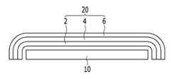
도 2는 도 1의 II-II선을 따라 잘라 도시한 단면도이다.FIG. 2 is a cross-sectional view taken along the line II-II of FIG. 1.
도 2에 도시한 바와 같이, 보호용 윈도우(20)는 연속해서 적층되어 있는 제1 투명 부재(2), 제2 투명 부재(4) 및 제3 투명 부재(60)를 포함한다.As shown in FIG. 2, the
제1 투명 부재(2)는 폴리카보네이트(polycarbonate, PC)로 이루어지며, 0.4mm 내지 1mm의 두께일 수 있다.The first
제2 투명 부재(4)는 폴리에틸렌프탈레이트(poly(ethylene terephthalate), PET) 또는 폴리에틸렌나프탈레이트(poly(ethylene naphthalate))으로 이루어질 수 있으며, 38㎛ 내지 100㎛의 두께일 수 있다.The second
제3 투명 부재(6)는 실세스퀴옥산(silsesquioxane)으로 이루어지며, 75㎛ 내지 150㎛의 두께일 수 있다. 제3 투명 부재(6)는 제2 투명 부재(4)와 물리적으로 결합되어 있다. 제2 투명 부재(4)의 표면은 나노 입자 처리가 되어 있어 제3 투명 부재(6)로부터 제2 투명 부재(4)를 용이하게 분리할 수 있도록 한다.The third
실세스퀴옥산은 실록산(siloxane)의 일종으로, 표 1에서와 같이 M, D, T, Q의 단위 구조를 포함한다. 이중, 실세스키옥산은 T 단위구조를 포함하는 중합체이며, 일반식 (RSiO3/2)n 로 표시될 수 있다. 실세스키옥산은 트리알콕시실록산(RSi(OR)3) 또는 트리클로로실란(RSiCl3)의 가수분해중합법에 의해 생성 가능하다. 몇몇 실시예에서는, 실세스키옥산은 가수분해중합법이 아닌 당업자에게 알려진 방법에 의하여 생성될 수도 있다.Silsesquioxane is a kind of siloxane and includes a unit structure of M, D, T, and Q as shown in Table 1. Of these, silsesquioxane may be represented by a polymer containing a structural unit T, the formula (RSiO3/2)n. Silsesquioxane can be produced by hydrolysis polymerization of trialkoxysiloxane (RSi (OR)3 ) or trichlorosilane (RSiCl3 ). In some embodiments, silsesquioxane may be produced by methods known to those skilled in the art, rather than by hydrolytic polymerization.

도 3 및 도 4는 본 발명의 다른 실시예들에 따른 보호용 윈도우의 단면도이다.3 and 4 are cross-sectional views of a protective window according to other embodiments of the present invention.
도 3에 도시한 바와 같이, 본 발명의 다른 실시예에 따른 보호용 윈도우(22)는 제1 투명 부재(2), 제2 투명 부재(4) 및 제3 투명 부재(6)를 포함한다.As shown in FIG. 3, the
제1 내지 제3 투명 부재는 도 1의 제1 내지 제3 투명 부재와 동일한 물질로 동일한 두께일 수 있다.The first to third transparent members may have the same thickness as the first to third transparent members of FIG. 1.
도 3의 보호용 윈도우(20)는 보호용 윈도우(20) 전체가 투명한 투명부로 이루어질 수 있으며 비투명 영역을 포함하지 않는다. 이와 같이 보호용 윈도우(20) 전체가 투명부로 이루어지면 표시 패널(10)의 측면까지 화소 영역을 형성하여 표시 영역으로 사용할 수 있다. 이때, 표시 패널(10)은 보호용 윈도우(20)와 같은 형태로 굽어질 수 있다.The
또한, 보호용 윈도우가 하나의 곡면을 포함할 경우 표시 패널(10) 또한 곡면과 대응하는 부분만 굽어지게 형성할 수 있다.In addition, when the protective window includes one curved surface, the
도 4에 도시한 바와 같이, 본 발명의 다른 실시예에 따른 보호용 윈도우(24)는 제1 투명 부재(2), 제2 투명 부재(4) 및 제3 투명 부재(6)를 포함한다. 그리고 제2 투명 부재(4)와 제3 투명 부재(6) 사이에 위치하는 하드 코팅층(8)을 더 포함한다.As shown in FIG. 4, the
하드 코팅층(8)은 유-무기 복합물질, PMMA(polymethyl methacrylate)계 물질 등으로 이루어질 수 있으며, 보호용 윈도우(20)의 강성을 더욱 증가시킨다.The
그럼 이하에서는 도 5 내지 도 9를 참조하여 본 발명에 따른 보호용 윈도우를 제조하는 방법에 대해서 구체적으로 설명한다.Hereinafter, a method of manufacturing a protective window according to the present invention will be described in detail with reference to FIGS. 5 to 9.
도 5는 본 발명의 한 실시예에 따른 보호용 윈도우를 제조하는 방법을 나타내는 순서도이고, 도 6 내지 도 9는 도 5의 순서도에 따라 보호용 윈도우를 제조하는 중간 단계에서의 단면도이다.5 is a flow chart showing a method of manufacturing a protective window according to an embodiment of the present invention, Figures 6 to 9 is a cross-sectional view at an intermediate step of manufacturing a protective window according to the flow chart of FIG.
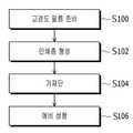
도 5에 도시한 바와 같이, 고경도 필름을 준비하는 단계(S100), 고경도 필름에 인쇄층을 형성하는 단계(S102), 가재단하는 단계(S104), 예비 성형하는 단계(S106), 사출 하는 단계(S108), 게이트를 제거하는 단계(S110)를 포함한다.As shown in Figure 5, preparing a high hardness film (S100), forming a printing layer on the high hardness film (S102), cutting step (S104), preforming step (S106), injection Step S108, and removing the gate S110.
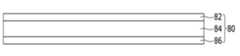
구체적으로 설명하면, 먼저 도 6에서와 같이 고경도 필름(800)을 준비(S100)한다. 고경도 필름(800)은 실세스퀴옥산으로 이루어지는 실세스퀴옥산 필름(84), 실세스퀴옥산 필름(84)의 양면에 부착되어 있는 제1 지지 필름(82)과 제2 지지 필름(86)을 포함한다. 그리고 제1 지지 필름(82)과 제2 지지 필름(86) 위에는 PE로 이루어지는 보호 필름(72)이 부착되어 있다.In detail, first, as shown in FIG. 6, the
제1 지지 필름(82)과 제2 지지 필름(86)은 실세스퀴옥산 필름(84)에 산소가 유입되어 실세스퀴옥산 필름이 분해되는 것을 방지하고, 예비 성형시에 실세스퀴옥산 필름(84)을 지지하여 깨지는 것을 방지할 수 있다.The
이때, 제1 지지 필름(82)과 제2 지지 필름(86)은 실세스퀴옥산 필름(84)을 지지하기 위해서 내충격성이 강한 물질로 탄성 계수가 우수한 물질을 사용하는 것이 바람직하며, 예를 들어 PET 또는 PEN으로 이루어질 수 있다.In this case, in order to support the
이때, 제2 지지 필름(86)와 실세스퀴옥산 필름(84)은 점착제로 결합하고 있으며, 제1 지지 필름(82)와 실세스퀴옥산 필름(84)은 물리적으로 결합하고 있다. 점착제의 종류에 대해서는 특별히 제한이 없으며, 광학적 투명성이 우수하고 내후성 및 내열성이 우수한 물질이면 모두 가능하며, 예를 들어 아크릴계 점착제일 수 있다.At this time, the
한편, 제1 지지 필름(82)와 제2 지지 필름(86)가 38㎛미만의 두께로 부착될 경우 실세스퀴옥산 필름(84)의 강성으로 인해서 성형 후 형상을 유지하기가 용이하지 않고, 188㎛초과의 두께로 부착될 경우 실세스퀴옥산 필름(84)과 제1 지지 필름(82) 및 제2 지지 필름(86)의 강성으로 인해서 성형이 용이하지 않아 제1 지지 필름(82)가 박리되거나, 실세스퀴옥산 필름(84)이 파손될 수 있다. 따라서 제1 지지 필름(82)와 제2 지지 필름(86)는 50㎛ 내지 100㎛의 두께일 수 있으며, 제1 지지 필름(82)와 제2 지지 필름(86)는 동일한 두께를 가진다.On the other hand, when the
실세스퀴옥산 필름(84)이 75㎛미만의 두께이면 연필 경도가 8H미만으로 떨어지며 표면 평탄도가 유지되지 않을 수 있고, 125㎛초과로 형성할 경우 강성이 증가하여 성형이 용이하지 않을 수 있다. 따라서 실세스퀴옥산 필름(84)은 75㎛ 내지 125㎛의 두께로 형성하는 것이 바람직하다.If the
다음, 도 7에 도시한 바와 같이 보호 필름(72)을 모두 제거한 후 노출된 제1 지지 필름(82)의 표면에 인쇄층(도시하지 않음)을 형성(S102)한다. 인쇄층은 비표시 영역을 가리기 위한 블랙 매트릭스일 수 있으며, 제품의 로고나 장식용 문양 등이 포함될 수 있다.Next, as shown in FIG. 7, after removing all of the
인쇄층은 패드 인쇄기 및 실크 스크린 인쇄기 등의 다양한 방법으로 형성한 후 건조하여 형성한다. 인쇄용 잉크는 이후의 사출 공정에서 주입되는 수지에 인쇄층이 밀리지 않고 수지층에 완전히 접착될 수 있도록 유색 잉크와 바인더(binder)가 혼합하여 사용한다. 이때, 바인더는 PMMA계나 PC계 등의 물질을 사용할 수 있다.The printing layer is formed by various methods such as a pad printing machine and a silk screen printing machine, and then dried. The printing ink is used by mixing colored ink and binder so that the printing layer is completely adhered to the resin layer without being pushed to the resin injected in the subsequent injection process. In this case, the binder may use a material such as PMMA or PC.
이후, 형성하고자 하는 윈도우의 크기보다 크게 고경도 필름(800)을 재단(S104)한다.Thereafter, the
다음, 도 8에 도시한 바와 같이, 재단된 고경도 필름(800)을 예비 성형용 지그(900)를 이용하여 윈도우 형상으로 예비성형(pre-forming)한다(S106). 예비성형은 진공 성형 또는 압공 성형으로 수행할 수 있다.Next, as shown in FIG. 8, the cut
진공 성형은 고경도 필름(800)을 클램프에 고정시킨 후 고경도 필름의 상부 및 하부에 히터를 배치하여 고경도 필름을 가열하여 연화시킨다. 이때, 가열은 250℃ 내지 500℃의 온도에서 5초 내지 10초 동안 진행한다. 500℃초과의 온도에서 진행할 경우 지지 부재의 결정화로 강성이 증가하여 실세스퀴옥산 필름이 파손될 수 있으며 열 변형이 용이하지 않는다.In the vacuum molding, the
이후, 히터를 제거한 후 지그 위에 고경도 필름을 안착시킨 후 진공 상태를 유지하여 고경도 필름이 지그의 표면에 밀착되면서 지그의 표면과 동일한 형태를 가지도록 예비성형하여 예비 윈도우를 형성한다. 그런 다음, 예비 윈도우(80)를 냉각한 후 지그와 분리한다. 지그(900)는 만곡된 부분을 포함하고, 지그(900)의 만곡된 부분에 의해서 예비 윈도우(80)는 모서리에 곡면이 형성된다.Subsequently, after removing the heater, the high hardness film is placed on the jig and the vacuum is maintained to preform the high hardness film to have the same shape as the surface of the jig while being in close contact with the surface of the jig to form a preliminary window. Then, the
압공 성형은 진공 성형과 마찬가지로 진공 상태를 유지하면서 고경도 필름에 고압 공기를 분사하여 고경도 필름을 지그의 표면에 완전히 밀착시켜 예비 윈도우를 형성한다. 이후, 예비 윈도우를 냉각한 후 지그와 분리한다.In the same way as vacuum forming, the pressure forming sprays high pressure air to the high hardness film while maintaining the vacuum state, thereby forming the preliminary window by closely contacting the high hardness film to the surface of the jig. Thereafter, the preliminary window is cooled and then separated from the jig.
한편, 고경도 필름을 지그에 안착시킨 후 밀착용 필름을 가열한 다음 고경도 필름 위에 밀착용 필름을 부착시킨 다음 진공 상태를 유지하여 예비 성형을 진행할 수 있다. 밀착용 필름은 ABS(acrylonitrile butadiene styrene copolymer), ABS/PC, PET와 같은 실리콘 필름으로 온도에 따라서 가역적으로 반응하는 물질로 250℃ 내지 500℃의 온도에서 5초 동안 가열한 후 고경도 필름 위에 부착한다.On the other hand, after mounting the high hardness film to the jig, the adhesive film may be heated, and then the adhesive film may be attached onto the high hardness film, and then preformed by maintaining the vacuum state. The adhesive film is a silicone film such as ABS (acrylonitrile butadiene styrene copolymer), ABS / PC, PET, which is reversibly reacted depending on the temperature. do.
이처럼 밀착용 필름을 사용하면 밀착용 필름이 고경도 필름을 덮고 있어, 진공으로 고경도 필름을 지그에 밀착시킬 때 고경도 필름과 지그 사이의 공기가 배기되면서 진공 상태를 형성하여 고경도 필름이 지그에 완전히 밀착될 수 있도록 한다.When the adhesive film is used, the adhesive film covers the high hardness film. When the high hardness film is closely adhered to the jig by vacuum, the air between the high hardness film and the jig is evacuated to form a vacuum state so that the high hardness film is jig. Make sure they are completely in contact with the
본 발명의 한 실시예에서와 같이 실세스퀴옥산 필름의 양면에 제1 지지 부재와 제2 지지 부재를 부착하면, 실세스퀴옥산 필름과 같이 취성이 강한 재료가 곡면을 형성하기 위해서 성형되더라도 제1 지지 부재와 제2 지지 부재에 지지되어 파괴되지 않고 곡면을 형성할 수 있다.When the first support member and the second support member are attached to both sides of the silsesquioxane film as in one embodiment of the present invention, even if a brittle material such as the silsesquioxane film is molded to form a curved surface, It is supported by the 1st support member and the 2nd support member, and can form a curved surface without breaking.
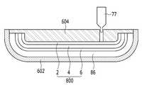
다음, 도 9에 도시한 바와 같이, 서로 맞물리는 형태를 가지도록 형성된 하부 금형(602)과 상부 금형(604)을 이용한 사출공정으로 윈도우를 형성할 수 있다. 이때, 하부 금형(602)과 상부 금형(604)의 내부는 형성하고자 하는 윈도우의 형상을 가지고, 상부 금형과 하부 금형 사이에 상기 예비 성형한 예비 윈도우를 안착시킨다. 상부 금형(604)과 하부 금형(602) 사이는 도 1의 제1 투명 부재(2)의 두께만큼 이격될 수 있다.Next, as shown in FIG. 9, a window may be formed by an injection process using the
이후, 하부 금형(602)과 상부 금형(604) 사이에 일정량의 수지(77)를 주입한다. 주입되는 수지(77)의 양은 제1 투명 부재(2) 두께에 따라서 정확하게 주입되는 것이 바람직하나, 일반적으로 형성는데 필요한 양보다 조금 많은 상태로 주입할 수 있다.Thereafter, a predetermined amount of
그런 다음 주입된 수지를 경화하여 제1 투명 부재(2)를 포함하는 보호용 윈도우(20)를 완성한다. 이때, 예비 윈도우의 제1 지지 부재는 도 1의 제2 투명 부재(4)가 되고, 실세스퀴옥산 필름은 제3 투명 부재(6)가 된다.Then, the injected resin is cured to complete the
사출공정으로 윈도우를 형성하면 수지가 주입되는 곳에 돌출부(gate)(도시하지 않음)가 형성된다. 따라서 레이저를 이용하여 돌출된 부분을 제거한다. 이때, 레이저는 파워가 큰 CO2 레이저로 제거할 수 있다.When the window is formed by the injection process, a gate (not shown) is formed where the resin is injected. Therefore, the protrusion is removed using a laser. At this time, the laser can be removed with a large power CO2 laser.
한편, 제2 지지 부재는 실세스퀴옥산 필름인 제3 투명 부재와 점착제로 부착되어 제3 투명 부재를 보호하기 위한 것으로 보호용 윈도우(20)를 완성한 후 제거한다.Meanwhile, the second support member is attached to the third transparent member, which is a silsesquioxane film, and an adhesive to protect the third transparent member, and is removed after completing the
상기에서는 본 발명의 바람직한 실시예에 대하여 설명하였지만, 본 발명은 이에 한정되는 것이 아니고 특허청구범위와 발명의 상세한 설명 및 첨부한 도면의 범위 안에서 여러 가지로 변형하여 실시하는 것이 가능하고 이 또한 본 발명의 범위에 속하는 것은 당연하다.Although the preferred embodiments of the present invention have been described above, the present invention is not limited thereto, and various modifications and changes can be made within the scope of the claims and the detailed description of the invention and the accompanying drawings. Naturally, it belongs to the range of.
2: 제1 투명 부재4: 제2 투명 부재
6: 제3 투명 부재10: 표시 패널
11: 표시 영역12: 비표시영역
13: 제1 기판14: 제2 기판
20: 보호용 윈도우22, 24: 윈도우
26: 구동 회로부30: 가요성 인쇄 회로
40: 하우징50: 인쇄 회로 기판
51: 커넥터52: 연장부
72: 보호 필름77: 수지
80: 예비 윈도우82: 제1 지지 필름
84: 실세스퀴옥산 필름86: 제2 지지 필름
100: 표시 장치211: 투명부
212: 불투명부602: 하부 금형
604: 상부 금형800: 고경도 필름
900: 지그2: first transparent member 4: second transparent member
6: 3rd transparent member 10: display panel
11: display area 12: non-display area
13: first substrate 14: second substrate
20:
26: drive circuit section 30: flexible printed circuit
40: housing 50: printed circuit board
51: connector 52: extension
72: protective film 77: resin
80: preliminary window 82: first support film
84: silsesquioxane film 86: second support film
100: display device 211: transparent part
212: opaque portion 602: lower mold
604: upper mold 800: high hardness film
900: jig
Claims (10)
Translated fromKorean상기 고경도 필름을 예비 성형하여 예비 윈도우를 형성하는 단계, 및
사출공정으로 상기 예비 윈도우의 일면에 폴리 카보네이트로 이루어진 투명 부재를 형성하는 단계
를 포함하고,
상기 제1 지지 부재와 상기 제2 지지 부재는 폴리에틸렌테레프탈레이트 또는 폴리에틸렌나프탈레이트로 이루어지는 보호용 윈도우의 제조 방법.Preparing a high hardness film in which a first support member, a silsesquioxane film, and a second support member are laminated;
Preforming the high hardness film to form a preliminary window, and
Forming a transparent member made of polycarbonate on one surface of the preliminary window by an injection process
Including,
And said first supporting member and said second supporting member are made of polyethylene terephthalate or polyethylene naphthalate.
상기 예비 성형하는 단계는 상기 고경도 필름을 가열한 후 지그 위에 상기 고경도 필름을 안착 시킨 후 진공 상태에서 진행하는 보호용 윈도우의 제조 방법.In claim 1,
The preforming step is a method of manufacturing a protective window that proceeds in a vacuum after the high hardness film is seated on a jig after heating the high hardness film.
상기 예비 윈도우는 곡면을 포함하는 보호용 윈도우의 제조 방법.In claim 2,
The preliminary window is a manufacturing method of a protective window comprising a curved surface.
상기 예비 성형하는 단계는 밀착용 필름을 가열한 후 지그 위에 안착된 상기 고경도 필름을 밀착 시킨 후 진공 상태에서 진행하는 보호용 윈도우의 제조 방법.In claim 1,
The preforming step is a method of manufacturing a protective window that proceeds in a vacuum after the close contact with the high hardness film seated on a jig after heating the film for adhesion.
상기 예비 윈도우는 곡면을 포함하는 보호용 윈도우의 제조 방법.In claim 4,
The preliminary window is a manufacturing method of a protective window comprising a curved surface.
상기 예비 성형하는 단계는 250℃ 내지 500℃의 온도에서 진행하는 보호용 윈도우의 제조 방법.In claim 1,
The preforming step is a method of producing a protective window proceeds at a temperature of 250 ℃ to 500 ℃.
상기 표시 패널 위에 위치하며 상기 표시 영역과 대응하는 평탄면과 상기 표시 패널의 모서리와 대응하는 곡면을 포함하는 보호용 윈도우를 포함하고,
상기 보호용 윈도우는
폴리카보네이트로 이루어지는 제1 투명 부재,
상기 제1 투명 부재 위에 위치하며 폴리에틸렌테레프탈레이트 또는 폴리에틸렌나프탈레이트로 이루어지는 제2 투명 부재,
상기 제2 투명 부재 위에 위치하며 실세스퀴옥산으로 이루어지는 제3 투명 부재, 및
상기 제2 투명 부재와 상기 제3 투명 부재 사이에 위치하는 하드 코팅층을 포함하는 표시 장치.A display panel including a display area for displaying an image,
A protective window positioned on the display panel and including a flat surface corresponding to the display area and a curved surface corresponding to an edge of the display panel;
The protective window
A first transparent member made of polycarbonate,
A second transparent member positioned on the first transparent member and made of polyethylene terephthalate or polyethylene naphthalate,
A third transparent member positioned on the second transparent member and composed of silsesquioxane;
And a hard coating layer disposed between the second transparent member and the third transparent member.
상기 표시 패널은 유기 발광 소자를 포함하는 표시 장치.In claim 7,
The display panel includes an organic light emitting element.
상기 제1 투명 부재의 두께는 0.4mm 내지 1mm이고,
상기 제2 투명 부재의 두께는 38㎛ 내지 100㎛이고,
상기 제3 투명 부재의 두께는 75㎛ 내지 150㎛인 표시 장치.In claim 7,
The thickness of the first transparent member is 0.4mm to 1mm,
The second transparent member has a thickness of 38 μm to 100 μm,
The thickness of the third transparent member is 75㎛ to 150㎛ display device.
Priority Applications (4)
| Application Number | Priority Date | Filing Date | Title |
|---|---|---|---|
| KR1020130071847AKR102084060B1 (en) | 2013-06-21 | 2013-06-21 | Manufacuring mehtod of protective window and display device produced by using the same |
| US14/109,055US9486950B2 (en) | 2013-06-21 | 2013-12-17 | Method of manufacturing protective window and display device produced by using the same |
| TW103100350ATWI623793B (en) | 2013-06-21 | 2014-01-06 | Method of manufacturing protective window and display device produced by using the same |
| CN201410006681.2ACN104228297B (en) | 2013-06-21 | 2014-01-07 | The display device for manufacturing the method for protectiveness form and being prepared using the protectiveness form |
Applications Claiming Priority (1)
| Application Number | Priority Date | Filing Date | Title |
|---|---|---|---|
| KR1020130071847AKR102084060B1 (en) | 2013-06-21 | 2013-06-21 | Manufacuring mehtod of protective window and display device produced by using the same |
Publications (2)
| Publication Number | Publication Date |
|---|---|
| KR20150000075A KR20150000075A (en) | 2015-01-02 |
| KR102084060B1true KR102084060B1 (en) | 2020-03-04 |
Family
ID=52110792
Family Applications (1)
| Application Number | Title | Priority Date | Filing Date |
|---|---|---|---|
| KR1020130071847AActiveKR102084060B1 (en) | 2013-06-21 | 2013-06-21 | Manufacuring mehtod of protective window and display device produced by using the same |
Country Status (4)
| Country | Link |
|---|---|
| US (1) | US9486950B2 (en) |
| KR (1) | KR102084060B1 (en) |
| CN (1) | CN104228297B (en) |
| TW (1) | TWI623793B (en) |
Families Citing this family (10)
| Publication number | Priority date | Publication date | Assignee | Title |
|---|---|---|---|---|
| KR102425001B1 (en)* | 2015-01-15 | 2022-07-25 | 삼성디스플레이 주식회사 | Flexible windoe and manufacturing method thereof and flexible display thereof |
| WO2016122191A1 (en)* | 2015-01-26 | 2016-08-04 | 주식회사 동진쎄미켐 | Coated product, and high-hardness curved surface hard coating method |
| KR102373615B1 (en)* | 2015-08-24 | 2022-03-15 | 삼성디스플레이 주식회사 | Display device having window member and fabricating mathod for window member |
| CN105228398B (en)* | 2015-11-04 | 2017-12-22 | 东莞星海丰电子有限公司 | Injection molding method of embedded hardened PC sheet and scratch-resistant hardened electronic product window |
| KR102538093B1 (en)* | 2016-06-28 | 2023-05-30 | 삼성디스플레이 주식회사 | Display device |
| JP2019008107A (en)* | 2017-06-23 | 2019-01-17 | 株式会社ジャパンディスプレイ | Display device and electronic device |
| KR102459607B1 (en)* | 2017-11-08 | 2022-10-31 | 삼성디스플레이 주식회사 | Window for display device, method for fabricating the same and display device the same |
| TWI677980B (en)* | 2019-04-17 | 2019-11-21 | 友達光電股份有限公司 | Light emitting device |
| US12151413B2 (en) | 2019-08-08 | 2024-11-26 | Preh Gmbh | Plastic composite panel and associated production method |
| DE102020115719A1 (en) | 2020-06-15 | 2021-12-16 | Preh Gmbh | A plastic composite panel imitating a ground diamond structure and the associated manufacturing process |
Citations (1)
| Publication number | Priority date | Publication date | Assignee | Title |
|---|---|---|---|---|
| JP2012183818A (en)* | 2011-02-17 | 2012-09-27 | Nippon Steel Chem Co Ltd | Method of manufacturing injection-molded body using hardcoat film laminate for injection molding |
Family Cites Families (12)
| Publication number | Priority date | Publication date | Assignee | Title |
|---|---|---|---|---|
| JP2006522696A (en) | 2003-02-21 | 2006-10-05 | ゼネラル・エレクトリック・カンパニイ | Weatherproof multilayer article and method for producing the same |
| JP2005060657A (en)* | 2003-04-21 | 2005-03-10 | Seiko Epson Corp | Resin composition for hybrid lens, hybrid lens and lens system |
| KR20070025205A (en) | 2005-09-01 | 2007-03-08 | (주)지엔씨 | Dual film keypad with two plastic films laminated |
| TW200726648A (en)* | 2006-01-12 | 2007-07-16 | Entire Technology Co Ltd | High-hardness optical film and manufacturing process for the same using in-mold technology |
| CN101666896B (en)* | 2008-09-05 | 2014-04-30 | 深圳富泰宏精密工业有限公司 | Shell assembly with window lens |
| JP2010105385A (en)* | 2008-09-30 | 2010-05-13 | Toyoda Gosei Co Ltd | Decorative sheet and decorative molding |
| KR20100070678A (en) | 2008-12-18 | 2010-06-28 | 제일모직주식회사 | Polycarbonate resin composition |
| KR100969192B1 (en) | 2009-12-08 | 2010-07-09 | 주식회사 우전앤한단 | Portable electronic products |
| KR101121449B1 (en) | 2011-07-15 | 2012-03-09 | (주)대호테크 | Bending device for window glass |
| JP5630428B2 (en)* | 2011-12-12 | 2014-11-26 | コニカミノルタ株式会社 | Cover glass for display |
| CN103182812A (en)* | 2011-12-30 | 2013-07-03 | 深圳富泰宏精密工业有限公司 | Plastic composite body and manufacturing method thereof |
| JP6229204B2 (en)* | 2013-05-16 | 2017-11-15 | 三菱ケミカル株式会社 | Resin laminate, manufacturing method thereof, and display front plate |
- 2013
- 2013-06-21KRKR1020130071847Apatent/KR102084060B1/enactiveActive
- 2013-12-17USUS14/109,055patent/US9486950B2/enactiveActive
- 2014
- 2014-01-06TWTW103100350Apatent/TWI623793B/enactive
- 2014-01-07CNCN201410006681.2Apatent/CN104228297B/enactiveActive
Patent Citations (1)
| Publication number | Priority date | Publication date | Assignee | Title |
|---|---|---|---|---|
| JP2012183818A (en)* | 2011-02-17 | 2012-09-27 | Nippon Steel Chem Co Ltd | Method of manufacturing injection-molded body using hardcoat film laminate for injection molding |
Also Published As
| Publication number | Publication date |
|---|---|
| US9486950B2 (en) | 2016-11-08 |
| US20140376237A1 (en) | 2014-12-25 |
| CN104228297B (en) | 2017-11-03 |
| TWI623793B (en) | 2018-05-11 |
| CN104228297A (en) | 2014-12-24 |
| TW201500807A (en) | 2015-01-01 |
| KR20150000075A (en) | 2015-01-02 |
Similar Documents
| Publication | Publication Date | Title |
|---|---|---|
| KR102084060B1 (en) | Manufacuring mehtod of protective window and display device produced by using the same | |
| KR102145388B1 (en) | Window for display device, display device comprising the same and manufacturing method thereof | |
| US10781128B2 (en) | Curved display device and manufacturing method thereof | |
| US8887425B2 (en) | Display device and method for manufacturing the same | |
| KR102084110B1 (en) | Cover window for display device, display device comprising the same, and mathod for manufacturing the same | |
| JP5406161B2 (en) | Input device and method for manufacturing input device | |
| CN106154675B (en) | A flexible electronic paper display device with ink layer and its manufacturing method | |
| KR102206376B1 (en) | Cover window for display device, display device comprising the same | |
| US9791753B2 (en) | Circuit substrate structure and method for manufacturing thereof | |
| CN105579938A (en) | Capacitive curved touch panel and method for fabrication thereof | |
| US20110122000A1 (en) | Control panel and control method thereof | |
| CN106502439B (en) | touch display device | |
| KR20140001579A (en) | Flexible display apparatus and the method for manufacturing the same | |
| CN205121507U (en) | Touch control display equipment | |
| KR20160086514A (en) | Cover window for display device, display device comprising the same, and method for manufacturing the same | |
| US20140055958A1 (en) | 3d touch module and its methode of manufacturing | |
| KR20210083546A (en) | Method of manufacturing organic light emitting display device | |
| CN112449524A (en) | Display device | |
| KR101516482B1 (en) | Surface panel equipped with detecting function | |
| JP2012098973A (en) | Glass composite and input device using the glass composite | |
| KR102352742B1 (en) | Cover window and display device comprising the same | |
| CN113711292A (en) | Display device and method of manufacturing display device | |
| JP2017040767A (en) | Display device | |
| CN102117708A (en) | Electrophoretic display button structure |
Legal Events
| Date | Code | Title | Description |
|---|---|---|---|
| PA0109 | Patent application | Patent event code:PA01091R01D Comment text:Patent Application Patent event date:20130621 | |
| PG1501 | Laying open of application | ||
| A201 | Request for examination | ||
| PA0201 | Request for examination | Patent event code:PA02012R01D Patent event date:20180604 Comment text:Request for Examination of Application Patent event code:PA02011R01I Patent event date:20130621 Comment text:Patent Application | |
| E902 | Notification of reason for refusal | ||
| PE0902 | Notice of grounds for rejection | Comment text:Notification of reason for refusal Patent event date:20190802 Patent event code:PE09021S01D | |
| E701 | Decision to grant or registration of patent right | ||
| PE0701 | Decision of registration | Patent event code:PE07011S01D Comment text:Decision to Grant Registration Patent event date:20191223 | |
| GRNT | Written decision to grant | ||
| PR0701 | Registration of establishment | Comment text:Registration of Establishment Patent event date:20200226 Patent event code:PR07011E01D | |
| PR1002 | Payment of registration fee | Payment date:20200226 End annual number:3 Start annual number:1 | |
| PG1601 | Publication of registration | ||
| PR1001 | Payment of annual fee | Payment date:20240125 Start annual number:5 End annual number:5 | |
| PR1001 | Payment of annual fee | Payment date:20250122 Start annual number:6 End annual number:6 |