KR102083769B1 - Wristwatch with receiver function - Google Patents
Wristwatch with receiver functionDownload PDFInfo
- Publication number
- KR102083769B1 KR102083769B1KR1020197025296AKR20197025296AKR102083769B1KR 102083769 B1KR102083769 B1KR 102083769B1KR 1020197025296 AKR1020197025296 AKR 1020197025296AKR 20197025296 AKR20197025296 AKR 20197025296AKR 102083769 B1KR102083769 B1KR 102083769B1
- Authority
- KR
- South Korea
- Prior art keywords
- unit
- cartilage conduction
- wrist watch
- display
- hand
- Prior art date
- Legal status (The legal status is an assumption and is not a legal conclusion. Google has not performed a legal analysis and makes no representation as to the accuracy of the status listed.)
- Active
Links
- 210000000707wristAnatomy0.000claimsabstractdescription148
- 210000000845cartilageAnatomy0.000claimsabstractdescription144
- 230000001133accelerationEffects0.000claimsabstractdescription82
- 238000001514detection methodMethods0.000claimsabstractdescription40
- 230000005540biological transmissionEffects0.000claimsabstractdescription17
- 210000000623ulnaAnatomy0.000claimsabstractdescription10
- 238000004891communicationMethods0.000claimsdescription21
- 238000000034methodMethods0.000claimsdescription21
- 230000033001locomotionEffects0.000claimsdescription19
- 238000009434installationMethods0.000claimsdescription3
- 230000005484gravityEffects0.000abstractdescription13
- 230000006870functionEffects0.000description46
- 230000001413cellular effectEffects0.000description22
- 230000008859changeEffects0.000description13
- 238000010586diagramMethods0.000description11
- 230000008569processEffects0.000description11
- 210000000613ear canalAnatomy0.000description10
- 210000000245forearmAnatomy0.000description9
- 238000012545processingMethods0.000description9
- 210000003811fingerAnatomy0.000description8
- 230000004044responseEffects0.000description8
- 210000003813thumbAnatomy0.000description8
- 230000005012migrationEffects0.000description6
- 238000013508migrationMethods0.000description6
- 210000004728ear cartilageAnatomy0.000description5
- 230000010355oscillationEffects0.000description5
- 238000002360preparation methodMethods0.000description5
- 238000003860storageMethods0.000description5
- 210000000988bone and boneAnatomy0.000description4
- 230000036571hydrationEffects0.000description4
- 238000006703hydration reactionMethods0.000description4
- 238000003384imaging methodMethods0.000description4
- 230000007246mechanismEffects0.000description4
- 238000003825pressingMethods0.000description4
- 230000007704transitionEffects0.000description4
- 239000000284extractSubstances0.000description3
- 230000002265preventionEffects0.000description3
- 230000000630rising effectEffects0.000description3
- 210000003454tympanic membraneAnatomy0.000description3
- 238000002224dissectionMethods0.000description2
- 210000004936left thumbAnatomy0.000description2
- 239000000463materialSubstances0.000description2
- 238000005259measurementMethods0.000description2
- 210000004935right thumbAnatomy0.000description2
- 230000005236sound signalEffects0.000description2
- 238000009825accumulationMethods0.000description1
- 239000012141concentrateSubstances0.000description1
- 230000008094contradictory effectEffects0.000description1
- 238000005520cutting processMethods0.000description1
- 230000002354daily effectEffects0.000description1
- 210000000883ear externalAnatomy0.000description1
- 210000003027ear innerAnatomy0.000description1
- 210000005069earsAnatomy0.000description1
- 230000000694effectsEffects0.000description1
- 230000003203everyday effectEffects0.000description1
- 210000005224forefingerAnatomy0.000description1
- 239000004973liquid crystal related substanceSubstances0.000description1
- 238000012986modificationMethods0.000description1
- 230000004048modificationEffects0.000description1
- 238000012546transferMethods0.000description1
Images


Classifications
- H—ELECTRICITY
- H04—ELECTRIC COMMUNICATION TECHNIQUE
- H04M—TELEPHONIC COMMUNICATION
- H04M1/00—Substation equipment, e.g. for use by subscribers
- H04M1/02—Constructional features of telephone sets
- H04M1/0202—Portable telephone sets, e.g. cordless phones, mobile phones or bar type handsets
- G—PHYSICS
- G04—HOROLOGY
- G04G—ELECTRONIC TIME-PIECES
- G04G21/00—Input or output devices integrated in time-pieces
- G04G21/06—Input or output devices integrated in time-pieces using voice
- G—PHYSICS
- G04—HOROLOGY
- G04G—ELECTRONIC TIME-PIECES
- G04G21/00—Input or output devices integrated in time-pieces
- G04G21/02—Detectors of external physical values, e.g. temperature
- G—PHYSICS
- G04—HOROLOGY
- G04G—ELECTRONIC TIME-PIECES
- G04G21/00—Input or output devices integrated in time-pieces
- G04G21/04—Input or output devices integrated in time-pieces using radio waves
- G—PHYSICS
- G04—HOROLOGY
- G04G—ELECTRONIC TIME-PIECES
- G04G9/00—Visual time or date indication means
- G04G9/08—Visual time or date indication means by building-up characters using a combination of indicating elements, e.g. by using multiplexing techniques
- H—ELECTRICITY
- H04—ELECTRIC COMMUNICATION TECHNIQUE
- H04B—TRANSMISSION
- H04B1/00—Details of transmission systems, not covered by a single one of groups H04B3/00 - H04B13/00; Details of transmission systems not characterised by the medium used for transmission
- H04B1/38—Transceivers, i.e. devices in which transmitter and receiver form a structural unit and in which at least one part is used for functions of transmitting and receiving
- H04B1/3827—Portable transceivers
- H04B1/385—Transceivers carried on the body, e.g. in helmets
- H—ELECTRICITY
- H04—ELECTRIC COMMUNICATION TECHNIQUE
- H04M—TELEPHONIC COMMUNICATION
- H04M1/00—Substation equipment, e.g. for use by subscribers
- H04M1/247—Telephone sets including user guidance or feature selection means facilitating their use
- H04M1/2474—Telephone terminals specially adapted for disabled people
- H—ELECTRICITY
- H04—ELECTRIC COMMUNICATION TECHNIQUE
- H04M—TELEPHONIC COMMUNICATION
- H04M1/00—Substation equipment, e.g. for use by subscribers
- H04M1/72—Mobile telephones; Cordless telephones, i.e. devices for establishing wireless links to base stations without route selection
- H04M1/724—User interfaces specially adapted for cordless or mobile telephones
- H04M1/72403—User interfaces specially adapted for cordless or mobile telephones with means for local support of applications that increase the functionality
- H04M1/72409—User interfaces specially adapted for cordless or mobile telephones with means for local support of applications that increase the functionality by interfacing with external accessories
- H04M1/72412—User interfaces specially adapted for cordless or mobile telephones with means for local support of applications that increase the functionality by interfacing with external accessories using two-way short-range wireless interfaces
- H—ELECTRICITY
- H04—ELECTRIC COMMUNICATION TECHNIQUE
- H04R—LOUDSPEAKERS, MICROPHONES, GRAMOPHONE PICK-UPS OR LIKE ACOUSTIC ELECTROMECHANICAL TRANSDUCERS; DEAF-AID SETS; PUBLIC ADDRESS SYSTEMS
- H04R1/00—Details of transducers, loudspeakers or microphones
- H04R1/02—Casings; Cabinets ; Supports therefor; Mountings therein
- H04R1/028—Casings; Cabinets ; Supports therefor; Mountings therein associated with devices performing functions other than acoustics, e.g. electric candles
- H—ELECTRICITY
- H04—ELECTRIC COMMUNICATION TECHNIQUE
- H04M—TELEPHONIC COMMUNICATION
- H04M1/00—Substation equipment, e.g. for use by subscribers
- H04M1/02—Constructional features of telephone sets
- H04M1/0202—Portable telephone sets, e.g. cordless phones, mobile phones or bar type handsets
- H04M1/026—Details of the structure or mounting of specific components
- H04M1/0266—Details of the structure or mounting of specific components for a display module assembly
- H—ELECTRICITY
- H04—ELECTRIC COMMUNICATION TECHNIQUE
- H04M—TELEPHONIC COMMUNICATION
- H04M1/00—Substation equipment, e.g. for use by subscribers
- H04M1/02—Constructional features of telephone sets
- H04M1/03—Constructional features of telephone transmitters or receivers, e.g. telephone hand-sets
- H—ELECTRICITY
- H04—ELECTRIC COMMUNICATION TECHNIQUE
- H04R—LOUDSPEAKERS, MICROPHONES, GRAMOPHONE PICK-UPS OR LIKE ACOUSTIC ELECTROMECHANICAL TRANSDUCERS; DEAF-AID SETS; PUBLIC ADDRESS SYSTEMS
- H04R2420/00—Details of connection covered by H04R, not provided for in its groups
- H04R2420/07—Applications of wireless loudspeakers or wireless microphones
- H—ELECTRICITY
- H04—ELECTRIC COMMUNICATION TECHNIQUE
- H04R—LOUDSPEAKERS, MICROPHONES, GRAMOPHONE PICK-UPS OR LIKE ACOUSTIC ELECTROMECHANICAL TRANSDUCERS; DEAF-AID SETS; PUBLIC ADDRESS SYSTEMS
- H04R2460/00—Details of hearing devices, i.e. of ear- or headphones covered by H04R1/10 or H04R5/033 but not provided for in any of their subgroups, or of hearing aids covered by H04R25/00 but not provided for in any of its subgroups
- H04R2460/13—Hearing devices using bone conduction transducers
Landscapes
- Engineering & Computer Science (AREA)
- Physics & Mathematics (AREA)
- Signal Processing (AREA)
- General Physics & Mathematics (AREA)
- Computer Networks & Wireless Communication (AREA)
- Human Computer Interaction (AREA)
- Acoustics & Sound (AREA)
- Computer Vision & Pattern Recognition (AREA)
- Telephone Function (AREA)
- Electric Clocks (AREA)
- Details Of Audible-Bandwidth Transducers (AREA)
- Telephone Set Structure (AREA)
Abstract
Translated fromKoreanDescription
Translated fromKorean본 발명은 수화 기능을 갖는 손목 시계에 관한 것이다.The present invention relates to a wrist watch having a sign language function.
손목 시계형의 수화 장치가 다양하게 제안되어 있다. 특허문헌 1에서는, 액추에이터에 의해 발생한 진동을 진동판으로부터 인체에 전달하고, 진동판의 진동을 골전도에 의해 손목으로부터 손가락에 전달하고, 이 손가락을 귓구멍 등에 삽입함으로써 음성 신호를 듣는 것이 제안되어 있다(특허문헌 1). 또한, 특허문헌 2에서는, 본원 발명자에 의해, 손목 시계의 벨트부 등에 설치된 손연골 전도 진동원으로부터 손목에 연골 전도용의 진동을 전달하고, 이 진동이 전달되는 집게 손가락 또는 엄지 손가락 또는 손바닥 하부를 귀연골에 대어 연골 전도에 의해 수화를 행하는 것이 제안되어 있다(특허문헌 2).A wristwatch-type hydration device has been proposed in various ways. In patent document 1, it is proposed to transmit the vibration generated by the actuator from the diaphragm to the human body, to transmit the vibration of the diaphragm from the wrist to the finger by bone conduction, and to listen to an audio signal by inserting the finger into the ear hole or the like (patent). Document 1). Moreover, in
그러나, 손의 진동을 통해 연골 전도를 발생시키는 수화 장치에 관해서는, 더 검토해야 할 과제가 많다.However, regarding the hydration device which generates cartilage conduction through the vibration of a hand, there are many subjects to consider further.
본 발명의 과제는, 상기를 감안하여, 손의 진동을 통해 연골 전도를 발생시키는 것에 의한 보다 효과적인 수화 기능을 갖는 손목 시계를 제공하는 것에 있다.SUMMARY OF THE INVENTION In view of the above, an object of the present invention is to provide a wrist watch having a more effective hydration function by generating cartilage conduction through vibration of a hand.
상기 과제를 해결하기 위해, 본 발명은 관찰 시에 있어서의 표시의 상하를 반전할 수 있는 표시부와, 장착 시에 요골의 원위단 근방 및 척골의 원위단에 접하는 부분에 각각 설치된 연골 전도용의 진동 전달부를 설치한 것을 특징으로 하는 수화 기능을 갖는 손목 시계를 제공한다. 구체적인 특징에 따르면, 장착 시에 손등측에 오는 위치에 조작부가 설치된다.MEANS TO SOLVE THE PROBLEM In order to solve the said subject, this invention provides the display part which can invert the upper and lower sides of the display at the time of observation, and the vibration transmission for cartilage conduction provided in the part which contact | connects the distal end near the distal end and the distal end of the ulna at the time of mounting Provided is a wristwatch having a sign language function, wherein the watch is provided. According to a specific feature, the operation portion is provided at a position coming to the back of the hand during mounting.
구체적인 특징에 따르면, 손목 시계는, 가속도 검지부와, 상기 가속도 검지부에 의해 검지되는 가속도에 기초하여 상기 표시부의 상하가 정립 상태로 되는 방향을 판단하는 판단부와, 상기 판단부의 판단에 기초하여 상기 표시부의 상하 방향을 결정함과 함께 그 판단에 반하는 상기 판단부에 의한 판단이 발생할 때까지 상기 상하 방향을 유지하는 표시 제어부를 갖는다. 보다 구체적인 특징에 따르면 상기 판단부는, 상기 조작부의 상하 방향과 상기 가속도 검지부에 의해 검지되는 가속도의 관계에 기초하여 상기 표시부의 상하를 정립 상태로 하는 방향을 판단한다. 다른 구체적인 특징에 따르면, 상기 판단부는, 상기 가속도 검지부에 의해 검지되는 중력 가속도의 평균값에 기초하여 상기 조작부가 상하 어느 것을 향하여 장착되어 있는지를 판단함과 함께, 상기 가속도 검지부에 의해 검지되는 비틀림 운동이 발생하는 순서와 방향의 평균값에 기초하여 손목 시계가 오른손에 장착되어 있는지 왼손에 장착되어 있는지를 판단하고, 그 조합에 기초하여 상기 표시부의 상하를 정립 상태로 하는 방향을 판단한다.According to a specific feature, the wristwatch includes an acceleration detection unit, a determination unit that determines a direction in which the upper and lower sides of the display unit are in a standing state based on the acceleration detected by the acceleration detection unit, and the display unit based on the determination of the determination unit. And a display control unit which determines the up and down direction of and maintains the up and down direction until a judgment by the determination unit contrary to the determination occurs. According to a more specific feature, the determination unit determines a direction in which the display unit is set up and down based on the relationship between the up and down direction of the operation unit and the acceleration detected by the acceleration detection unit. According to another specific feature, the determination unit determines whether the operation unit is mounted upward or downward based on the average value of the gravity acceleration detected by the acceleration detection unit, and the torsional motion detected by the acceleration detection unit It is judged whether the wristwatch is mounted on the right hand or the left hand on the basis of the average value of the order and the direction in which it occurs, and on the basis of the combination, the direction in which the display unit is set up and down is determined.
다른 구체적인 특징에 따르면, 손목 시계는 상기 표시부에 있어서의 상하의 반전에 연동하여, 연골 전도용의 진동 전달부 중 상기 요골의 원위단 근방에 오는 쪽을 선택적으로 진동시킨다. 다른 구체적인 특징에 따르면, 상기 요골의 원위단 근방 및 척골의 원위단에 접하는 부분에 각각 설치된 연골 전도용의 진동 전달부의 쌍방을 진동시킨다.According to another specific feature, the wristwatch selectively vibrates the one coming near the distal end of the radial among the vibration transmission units for cartilage conduction in conjunction with the up and down inversion of the display unit. According to another specific feature, vibrating both of the vibration transmitting portion for cartilage conduction, respectively provided in the vicinity of the distal end of the radial and in contact with the distal end of the ulna.
본 발명의 다른 특징에 따르면, 관찰 시에 있어서의 표시의 상하를 반전할 수 있는 표시부와, 가속도 검지부와, 상기 가속도 검지부에 의해 검지되는 가속도에 기초하여 상기 표시부의 상하가 정립 상태로 되는 방향을 판단하는 판단부와, 상기 판단부의 판단에 기초하여 상기 표시부의 상하 방향을 결정함과 함께 그 판단에 반하는 상기 판단부에 의한 판단이 발생할 때까지 상기 상하 방향을 유지하는 표시 제어부를 갖는 것을 특징으로 하는 수화 기능을 갖는 손목 시계가 제공된다. 구체적인 특징에 따르면, 손목 시계는, 장착 시에 손등측에 오는 위치에 설치되는 조작부를 갖고, 상기 판단부는, 상기 조작부의 상하 방향과 상기 가속도 검지부에 의해 검지되는 가속도의 관계에 기초하여 상기 표시부의 상하를 정립 상태로 하는 방향을 판단한다.According to another feature of the present invention, the display unit capable of inverting the display up and down at the time of observation, the acceleration detection unit, and the direction in which the up and down of the display unit is in the upright position based on the acceleration detected by the acceleration detection unit. And a display control unit which determines a vertical direction of the display unit based on the determination of the determination unit and maintains the vertical direction until a determination by the determination unit contrary to the determination occurs. A wrist watch having a sign language function is provided. According to a specific feature, the wristwatch has an operation unit provided at a position coming to the back of the hand when mounted, and the determination unit is based on the relationship between the up and down direction of the operation unit and the acceleration detected by the acceleration detection unit. The direction of making the up-and-down upright state is judged.
다른 구체적인 특징에 따르면, 상기 판단부는, 상기 가속도 검지부에 의해 검지되는 중력 가속도의 평균값에 기초하여 상기 조작부가 상하 어느 것을 향하여 장착되어 있는지를 판단함과 함께, 상기 가속도 검지부에 의해 검지되는 비틀림 운동이 발생하는 순서와 방향의 평균값에 기초하여 손목 시계가 오른손에 장착되어 있는지 왼손에 장착되어 있는지를 판단하고, 그 조합에 기초하여 상기 표시부의 상하를 정립 상태로 하는 방향을 판단한다. 다른 구체적인 특징에 따르면 상기 판단부는, 상기 가속도 검지부에 의해 검지되는 중력 가속도의 평균값에 기초하여 상기 조작부가 상하 어느 것을 향하여 장착되어 있는지를 판단함과 함께, 상기 가속도 검지부에 의해 검지되는 비틀림 운동이 발생하는 순서와 방향의 평균값에 기초하여 손목 시계가 오른손에 장착되어 있는지 왼손에 장착되어 있는지를 판단하고, 그 조합에 기초하여 상기 표시부의 상하를 정립 상태로 하는 방향을 판단한다.According to another specific feature, the determination unit determines whether the operation unit is mounted upward or downward based on the average value of the gravity acceleration detected by the acceleration detection unit, and the torsional motion detected by the acceleration detection unit It is judged whether the wristwatch is mounted on the right hand or the left hand on the basis of the average value of the order and the direction in which it occurs, and on the basis of the combination, the direction in which the display unit is set up and down is determined. According to another specific feature, the determination unit determines whether the operation unit is mounted upward or downward based on the average value of the gravity acceleration detected by the acceleration detection unit, and generates a torsional motion detected by the acceleration detection unit. On the basis of the order and the average value of the direction, it is determined whether the wristwatch is mounted on the right hand or the left hand, and based on the combination, the direction in which the display unit is set up and down is determined.
본 발명의 다른 특징에 따르면, 왼손에 채운 상태에서 표시부가 정립되어 보임과 함께 조작부가 손등측에 오는 왼손용 손목 시계와 오른손에 채운 상태에서 표시부가 정립되어 보임과 함께 조작부가 손등측에 오는 오른손용 손목 시계를 갖고, 상기 오른손용 손목 시계 및 왼손용 손목 시계 중 어느 것에도 장착 시에 요골의 원위단 근방에 접하는 부분에 연골 전도용의 진동 전달부를 배치한 것을 특징으로 하는 왼손용의 수화 기능을 갖는 손목 시계 및 오른손용의 수화 기능을 갖는 손목 시계가 제공된다.According to another feature of the present invention, the display is established in the state filled with the left hand and the left hand wrist watch that the control unit is on the back of the hand and the display is established in the state filled in the right hand and the right hand the control unit on the back of the hand The left hand sign language function is provided, and the vibration transmission part for cartilage conduction is arrange | positioned in the part which contact | abuts the distal end of the radial field when it is attached to either the said right hand watch and the left hand watch. There is provided a wrist watch having a hand watch and a sign language function for the right hand.
본 발명의 다른 특징에 따르면, 오른손에 채운 상태에서 정립하여 보이는 표시부와, 오른손에 채운 상태에서 손등측에 오는 조작부와, 오른손에 채웠을 때 오른손 요골의 원위단 근방에 접하는 부분에 배치되는 연골 전도용의 진동 전달부를 갖는 것을 특징으로 하는 오른손용의 수화 기능을 갖는 손목 시계가 제공된다.According to another feature of the present invention, cartilage conduction is disposed on the display portion that is seen standing up in the right hand state, the operation unit coming to the back of the hand in the state filled with the right hand, and the portion in contact with the distal end of the right hand radius when the right hand is filled. There is provided a wrist watch having a sign language function for the right hand, characterized by having a vibration transmitting unit.
상기한 바와 같이, 본 발명에 따르면, 보다 유용한 수화 기능을 갖는 손목 시계가 제공된다.As described above, according to the present invention, a wrist watch having a more useful sign language function is provided.
도 1은 본 발명의 실시 형태에 따른 실시예 1의 시스템 구성을 도시하는 사시도이다(실시예 1).
도 2는 실시예 1에 있어서의 손목 시계 표시부에 표시되는 통화 자세의 설명 화면이다.
도 3은 실시예 1에 있어서의 손목 시계 표시부에 표시되는 통화 자세의 다른 설명 화면이다.
도 4는 실시예 1에 있어서의 손목 시계 표시부에 표시되는 통화 자세의 또 다른 설명 화면이다.
도 5는 실시예 1의 블록도이다.
도 6은 실시예 1에 있어서의 손목 시계형 송수화 장치의 기능을 나타내는 흐름도이다.
도 7은 실시예 1에 있어서의 손목 시계형 송수화 장치의 다른 기능을 나타내는 흐름도이다.
도 8은 본 발명의 실시 형태에 따른 실시예 2의 시스템 구성을 도시하는 사시도이다(실시예 2).
도 9는 실시예 2의 블록도이다.
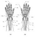
도 10은 실시예 2의 손목 시계형 송수화 장치를 장착한 전완부의 해부 모식도이다.
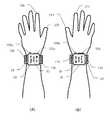
도 11은 실시예 2의 손목 시계형 송수화 장치를 장착한 전완부의 상면도이다.
도 12는 다양한 장착 상태를 표시의 관찰 방향으로부터 도시한 전완부의 상면도이다.
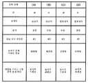
도 13은 도 12에 도시한 다양한 장착 상태에 있어서의 손, 조작부, 표시, 및 사용되는 연골 전도 진동원의 관계를, 도 12에서의 설명에 기초하여 정리한 표이다.
도 14는 조작부의 방향과 장착되는 손의 자동 판정에 관한 왼손 개념 설명도이다.
도 15는 조작부의 방향과 장착되는 손의 자동 판정에 관한 오른손 개념 설명도이다.
도 16은 손목 시계 표시부에 표시되는 오른손에 관한 통화 자세의 설명 화면이다.
도 17은 손목 시계 표시부에 표시되는 오른손의 다른 통화 자세의 설명 화면이다.
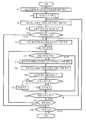
도 18은 실시예 2에 있어서의 손목 시계형 송수화 장치의 제어부의 기능을 나타낸 흐름도이다.
도 19는 도 18에 있어서의 스텝 S104의 상세를 나타내는 흐름도이다.1 is a perspective view showing a system configuration of a first embodiment according to an embodiment of the present invention (Example 1).
FIG. 2 is an explanation screen of a call posture displayed on the wrist watch display unit according to the first embodiment. FIG.
3 is another explanatory screen of a call posture displayed on the wrist watch display unit according to the first embodiment.
4 is another explanatory screen of a call attitude displayed on the wrist watch display unit according to the first embodiment.
5 is a block diagram of Embodiment 1. FIG.
6 is a flowchart showing the function of the wrist watch-type handset according to the first embodiment.
7 is a flowchart showing another function of the wrist watch-type handset according to the first embodiment.
8 is a perspective view showing a system configuration of a second embodiment according to an embodiment of the present invention (Example 2).
9 is a block diagram of
It is a schematic diagram of the dissection of the forearm equipped with the wristwatch type handset of Example 2. FIG.
11 is a top view of the forearm equipped with the wrist watch-type handset of Example 2. FIG.
12 is a top view of the forearm showing various mounting states from the viewing direction of the display;
FIG. 13 is a table summarizing the relationship between the hand, the operation unit, the display, and the cartilage conduction vibration source used in the various mounting states shown in FIG. 12 based on the description in FIG. 12.
It is a left hand conceptual explanatory drawing about the automatic determination of the direction of an operation part, and a hand mounted.
15 is an explanatory diagram of the right hand concept of automatic determination of the direction of the operation unit and the hand to be mounted.
16 is an explanatory screen of a call posture with respect to the right hand displayed on the wrist watch display.
17 is an explanatory screen of another call posture of the right hand displayed on the wrist watch display.
18 is a flowchart showing the function of the control unit of the wrist watch-type handset according to the second embodiment.
19 is a flowchart showing the details of step S104 in FIG. 18.
실시예 1Example 1
도 1은 본 발명의 실시 형태에 따른 실시예 1의 시스템 구성을 도시하는 사시도이다. 실시예 1은 상기 특허문헌 2에 기재한 것의 인용이며, 본 발명의 일부를 구성한다. 실시예 1은 휴대 전화(2)와 손목 시계형 송수화 장치(4)를 포함하는 시스템을 구성하고 있다. 휴대 전화(2)는, GUI(그래피컬·유저·인터페이스) 기능을 구비한 표시부(6)를 갖는 소위 스마트폰으로서 구성되어 있다. 텐키 등의 조작부(8)는 표시부(6) 상에 표시되고, 표시부(6)에 대한 손가락의 터치나 슬라이드에 따라 GUI 조작된다. 적외광 발광부(10 및 12)와 적외 수광부(14)는, 휴대 전화(2)가 귀에 접촉된 것을 검지하는 근접 센서를 구성한다. 휴대 전화(2)는 또한, 이어폰(16), 마이크(18) 및 텔레비전 전화용 내측 카메라(20)를 갖는다. 또한, 도 1에서는 도시하고 있지 않지만, 휴대 전화(2)는 표시부(6)의 이면측에 배면 주 카메라를 가짐과 함께, Bluetooth(등록 상표) 등에 의한 근거리 통신 시스템의 전파(22)에 의해 손목 시계형 송수화 장치(4)와 근거리 통신 가능하다. 휴대 전화(2)는 또한 착신음이나 텔레비전 전화의 발생을 위한 스피커를 갖고 있지만, 이것과 구별하기 위해, 귀에 접촉하여 듣는 스피커는 상기와 같이 「이어폰(16)」이라고 칭하고 있다.1 is a perspective view showing a system configuration of a first embodiment according to an embodiment of the present invention. Example 1 is a quotation of what was described in the said
손목 시계형 송수화 장치(4)는, 손목 시계 본체(26)와 벨트부(28)를 갖는다. 손목 시계 본체(26)에는 반사형 액정을 사용한 손목 시계 표시부(30)가 설치되어 있고, 통상의 시각 표시와 함께, 후술하는 다양한 표시를 행한다. 손목 시계 표시부(30)는 터치 패널식으로, 표시면에 터치 패널(30a)을 갖고, 손목 시계형 송수화 장치(4)를 조작하는 것이 가능하다. 손목 시계 본체(26)에는, 송수화 장치용 스피커(32)가 설치되어 있고, 휴대 전화(2)와의 근거리 통신에 의해, 휴대 전화(2)를 예를 들어 포켓에 넣은 상태에서도 손목 시계형 송수화 장치(4)를 보면서 통화가 가능하다. 송수화 장치용 마이크에 대해서는 후술한다. 손목 시계 본체(26)에는, 또한 카메라부(34)가 설치되어 있어 손목 시계 표시부(30)를 보고 있는 자신의 얼굴이 촬상됨과 함께, 상대의 얼굴이 손목 시계 표시부(30)에 표시되어, 텔레비전 전화가 가능하다.The wrist watch-
손목 시계 본체(26)에는, 압전 바이모르프 소자 등으로 이루어지는 연골 전도 진동원(36)이 설치되어 있고, 손목 시계 본체(26)의 이면측으로부터 손목에 연골 전도용의 진동을 전달한다. 또한, 벨트부(28)에도, 마찬가지의 압전 바이모르프 소자 등으로 이루어지는 연골 전도 진동원(38 및 40)이 설치되어 있고, 벨트부(28)의 이면측으로부터 손목에 연골 전도용의 진동을 전달한다. 또한, 벨트부(28)에는 손목과 음향 임피던스가 서로 비슷한 재질로 구성된 전도대(41)가 설치되어 있고, 연골 전도 진동원(38 및 40)은 이 전도대(41)에 배치되어 있고, 진동이 전도대(41)를 전달되도록 구성된다. 이와 같이 하여 손목 시계형 송수화 장치(4)로부터는 손목 주위의 광범위에 연골 전도용의 진동이 전달된다. 손목 주위의 광범위로부터 진동을 전달하는 구성은, 진동 전달을 위한 적합 위치의 개인차나, 손목 시계형 송수화 장치(4)의 장착 중의 위치 어긋남 등을 흡수하는 데 효과적이다. 또한, 손목 주위의 광범위로부터 진동을 전달함으로써 연골 전도를 위한 진동을 보다 효과적으로 손에 전달할 수 있다.The
여기서 연골 전도에 대해 설명한다. 연골 전도는, 본원 발명자에 의해 발견된 현상이며 이주 등의 외이도 입구부 둘레의 연골에 전달된 진동에 의해 연골부 외이도 표면이 진동하고, 외이도 내에서 기도음을 발생시키는 현상이다. 그리고 외이도 내에서 발생한 기도음은 외이도 내를 더욱 안측으로 진행하여 고막에 도달한다. 이와 같이 연골 전도에 의해 들리는 소리의 주요부는 고막을 통해 들리는 소리이다. 단, 고막에서 들리는 것은 통상의 기도음과 같이 외이도 외부로부터 외이도에 침입한 소리가 아니라, 어디까지나 외이도 내부에서 발생한 기도음이다.Cartilage conduction is explained here. Cartilage conduction is a phenomenon discovered by the inventors of the present invention and is a phenomenon in which the surface of the cartilage outer ear canal vibrates due to vibration transmitted to the cartilage around the inlet of the ear canal, such as migration, and generates airway sounds in the ear canal. And the airway sound generated in the ear canal proceeds further to the inner ear and reaches the eardrum. Thus, the main part of the sound heard by cartilage conduction is the sound heard through the eardrum. However, what is heard from the tympanic membrane is not a sound that invades the external ear canal from the outside of the ear canal as in the normal airway sound, but is an airway sound generated inside the ear canal to the last.
상기한 각 연골 전도 진동원은, 착신 바이브레이터의 진동원을 겸하고 있고, 휴대 전화(2)와의 근거리 통신에 의해, 착신 신호가 전달됨으로써 진동하여 손목에의 진동 전달에 의해 착신을 알린다. 또한, 후술하는 바와 같이, 연골 전도 진동원은 연골 전도 시에는 음성 신호의 주파수 영역(1000㎐를 중심으로 하는 주파수)에서 진동됨과 함께 불쾌한 진동이 손목에 감지되지 않도록 진동각을 일으키는 주파수(예를 들어 20㎐ 이하)를 커트하여 손목에 전달된다. 한편, 착신 바이브레이터로서 진동시킬 때에는, 진동각을 일으키는 주파수(예를 들어 20㎐ 이하)를 중심으로 진동되고, 가청 주파수 영역은 커트하여 다른 사람에게는 들리지 않도록 한다.Each of the cartilage conduction vibration sources described above serves as a vibration source of the incoming vibrator, and the incoming signal is transmitted by short-range communication with the
벨트부(28)에는, 조임 기구(42)가 설치되어 있고, 손목 시계형 송수화 장치(4)의 착탈 시에 벨트부(28)를 느슨하게 함과 함께, 통상 장착 상태의 조임을 행한다. 조임 기구(42)는, 또한 통상 상태로부터, 고통이나 불쾌감이 없는 범위에서 약간 꽉 끼게 벨트부(28)를 조임으로써 손목에의 연골 전도를 보다 확실하게 한다. 이러한 조임 기구(42)에 의한 통상 상태로부터 연골 전도 상태로의 전환은, 손목 시계 표시부(30)에 표시되는 스위치부(44)를 누르는 것에 의한 터치 패널 조작에 의해 가능하다. 또한, 스위치(44)를 누르는 동작은, 손목 시계 본체(26)를 손목에 압박하는 방향의 조작이므로 연골 전도 진동원(36)의 진동을 보다 확실하게 손목에 밀착시키는 동작으로도 된다. 또한, 통상 장착 상태에 있어서 연골 전도가 충분할 때에는, 스위치부(44)를 누르지 않고 통화하는 것도 가능하다.The
벨트부(28)에는, 또한 송수화 장치용의 가변 지향성 마이크(46)가 설치되어 있다. 상기한 텔레비전 전화 상태에서는, 화살표(48)로 나타내는 바와 같이 가변 지향성 마이크(46)는 손목 시계 표시부(30)의 정면으로부터의 음성을 얻도록 손등측에 지향성이 설정된다. 한편, 연골 전도에 의해 통화를 행할 때에는, 화살표(50)로 나타내는 바와 같이 가변 지향성 마이크(46)는 손목 시계형 송수화 장치(4)를 채운 손(통상 왼손)의 손바닥측으로부터의 음성을 얻도록 지향성이 전환되므로 후술하는 바와 같은 자세에 의해 통화가 가능해진다. 또한, 벨트부(28)에는, 음향 임피던스가 다른 재질로 이루어지는 진동 격리대(52 및 54)가 설치되어 있고, 연골 전도 진동원(36, 38 및 40)으로부터의 진동이 가변 지향성 마이크(46)에 전달되지 않도록 하고 있다. 또한, 벨트부(28)를 따라, 근거리 통신부의 안테나(56)가 손목을 감도록 설치되어 있다.The
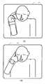
도 2는 도 1에 도시하는 실시예 1에 있어서의 손목 시계 표시부(30)에 표시되는 통화 자세의 설명 화면이다. 이 화면은, 손목 시계형 송수화 장치(4)의 전원 스위치를 켤 때마다 표시되지만, 번잡할 때에는 표시되지 않도록 설정할 수도 있다. 도 2의 (A)는 텔레비전 전화 시의 통화 자세이며, 휴대 전화(2)를 예를 들어 포켓에 넣은 상태에서 손목 시계 표시부(30)를 보면서 텔레비전 전화의 통화를 행하는 자세를 설명하고 있다. 이때 가변 지향성 마이크(46)의 지향성은 도 1의 화살표(48)로 나타내는 바와 같이 손등측을 향하고 있다.FIG. 2 is an explanation screen of a call posture displayed on the wrist
도 2의 (B)는 연골 전도 통화의 자세를 설명하는 것으로, 손목 시계형 송수화 장치(4)를 채운 손(예를 들어 왼손)의 검지 손가락을 동일한 측의 귀(예를 들어 왼쪽 귀)의 이주(귀 연골)에 접촉하고 있는 연골 전도에 의한 통화 자세를 나타내고 있다. 이때, 손가락으로 귓구멍을 막지 않도록 하면, 외계음도 들리는 상태에서 연골 전도에 의해 소리를 들을 수 있다. 또한, 이주를 강하게 눌러 귓구멍을 막도록 하면 외이도 폐쇄 효과에 의해 더욱 큰 소리로 연골 전도에 의한 소리를 들을 수 있다. 이러한 통화 자세에 의해, 손목으로부터 도입된 연골 전도를 위한 진동이 검지 손가락에 전달되고, 그 진동이 이주(귀 연골)에 전달됨으로써, 양호한 연골 전도에 의해 상대의 목소리를 들을 수 있음과 함께, 도 1의 화살표(50)로 나타내는 바와 같이 손바닥측의 방향으로 지향성이 전환된 가변 지향성 마이크(46)에 의해 얻어지는 자신의 목소리를 상대에게 전달할 수 있다. 또한, 이 자세 시, 카메라부(34), 송수화 장치용 스피커(32) 및 손목 시계 표시부(30)는 각각 오프가 된다. 이러한 자동 오프는, 손목 시계 본체(26)에 설치된 가속도 센서가 도 2의 (A)와 (B)의 자세 변경을 검지함으로써 자동적으로 행해진다.FIG. 2B illustrates the posture of the cartilage conduction call, in which the index finger of the hand (for example, the left hand) with the wristwatch-
도 3은 도 1에 도시하는 실시예 1에 있어서의 손목 시계 표시부(30)에 표시되는 통화 자세의 다른 설명 화면이다. 도 3의 (A)는 도 2의 (B)에 나타내는 연골 전도에 의한 통화 자세에 있어서, 오른손으로 도 1에 도시하는 스위치부(44)를 누르고 있는 상태를 나타낸다. 또한, 도 3의 (B)는 다른 연골 전도에 의한 통화 자세를 나타내는 것으로, 손목 시계형 송수화 장치(4)를 채운 손(예를 들어 왼손)의 엄지 손가락을 동일한 측의 귀(예를 들어 왼쪽 귀)의 이주(귀 연골)에 접촉한 자세를 나타내고 있다. 또한, 이 통화 자세에서도, 손바닥측의 방향으로 지향성이 전환된 가변 지향성 마이크(46)에 의해 얻어지는 자신의 목소리를 상대에게 전달할 수 있다.3 is another explanatory screen of a call posture displayed on the wrist
도 4는 도 1에 도시하는 실시예 1에 있어서의 손목 시계 표시부(30)에 표시되는 통화 자세의 또 다른 설명 화면이다. 도 4의 (A)는 손목 시계형 송수화 장치(4)를 채운 손(예를 들어 왼손)을 얼굴 앞에서 크로스시켜 검지 손가락을 반대측의 귀(예를 들어 오른쪽 귀)의 이주(귀 연골)에 접촉하고 있는 연골 전도에 의한 통화 자세를 나타내고 있다. 또한, 도 4의 (B)는 또 다른 연골 전도에 의한 통화 자세를 나타내는 것으로, 손목 시계형 송수화 장치(4)를 채운 손(예를 들어 왼손)의 손바닥 하부의 볼록한 부분을 동일한 측의 귀(예를 들어 왼쪽 귀)에 접촉한 자세를 나타내고 있다. 이 경우에는 손바닥의 볼록한 부분이 귓구멍 부근의 연골에 광범위하게 접촉하게 된다. 또한 강하게 누르면 귀를 막는 형태가 된다. 또한, 도 4의 (A) 및 도 4의 (B)의 어느 통화 자세에서도, 손바닥측의 방향으로 지향성이 전환된 가변 지향성 마이크(46)에 의해 얻어지는 자신의 목소리를 상대에게 전달할 수 있다.FIG. 4 is another explanatory screen of the call posture displayed on the wrist
도 5는 도 1에 나타낸 실시예 1의 블록도이며, 도 1과 동일 부분에는 도 1과 동일 번호를 부여하고, 필요가 없는 한, 설명은 생략한다. 휴대 전화(2)는, 기억부(58)에 기억되는 프로그램에 따라 동작하는 제어부(60)에 의해 제어된다. 기억부(58)는 또한, 제어부(60)의 제어에 필요한 데이터를 일시 기억함과 함께, 다양한 측정 데이터나 화상도 기억할 수 있다. 표시부(6)의 표시는 제어부(60)의 제어에 기초하여 표시 드라이버가 유지하는 표시 데이터에 기초하여 행해진다. 표시부(6)는 표시용 백라이트를 갖고 있으며, 주위의 밝기에 기초하여 제어부(60)가 그 밝기를 조절한다. 표시부(6)는 터치 패널(6a)을 갖고, 표시부(6)를 터치함으로써 휴대 전화(2)를 조작할 수 있다.FIG. 5 is a block diagram of the first embodiment shown in FIG. 1, and the same parts as in FIG. 1 are assigned the same numbers as in FIG. 1, and description is omitted unless necessary. FIG. The
송화 처리부(62), 마이크(18), 수화 처리부(64) 및 이어폰(16)을 포함하는 전화 기능부(66)는, 제어부(60)의 제어하에 있는 전화 통신부(68)에 의해, 무선 전화 회선에 접속 가능하다. 스피커(70)는, 제어부(60)의 제어에 의해 착신음이나 다양한 안내를 행함과 함께 텔레비전 전화 시의 상대의 목소리를 출력한다. 이 스피커(70)의 음성 출력은, 이어폰(16)으로부터 출력되는 일은 없다. 또한, 화상 처리부(72)는, 제어부(60)에 제어되어 텔레비전 전화용 내측 카메라(20) 및 배면 주 카메라(74)에 의해 촬상되는 화상을 처리하고, 이들의 처리 결과의 화상을 기억부(58)에 입력한다.The
휴대 전화(2)는, 손목 시계형 송수화 장치(4)와 통신하기 위한 근거리 통신부(76), 주전원의 메인 스위치 등의 조작부(78)를 갖는다. 휴대 전화(2) 전체에 급전하는 전원부(80)는 무접점 충전부(82)로부터 급전되는 충전지를 갖는다.The
손목 시계형 송수화 장치(4)는, 휴대 전화(2)와 통신하기 위한 근거리 통신부(77)를 갖는다. 또한 통상의 시계 기능을 위한 시계 기능부(84)를 갖는다. 가속도 센서(86)는, 도 1의 (A)로부터 (B)로의 손목 시계형 송수화 장치(4)의 상승, 및 도 1의 (B)로부터 (A)로의 손목 시계형 송수화 장치(4)의 하강을 검지하고, 카메라부(34), 스피커(32) 및 손목 시계 표시부(30)의 자동 전환을 행한다.The wrist watch-
손목 시계형 송수화 장치(4)의 전원부(88) 및 휴대 전화(2)의 전원부(80)는 각각, 무접점 충전부(82 및 90)에 의해 무접점 충전이 가능하지만, 서로의 충전 상태의 정보를 근거리 통신에 의해 공유하고, 손목 시계형 송수화 장치(4)와 휴대 전화(2)의 연계를 확보하도록 하고 있다. 또한, GPS부(92)는 손목 시계형 송수화 장치(4)를 채운 유저의 이동을 검지하고, 그때마다, 휴대 전화(2)가 비휴대 상태에서 원래의 장소에 방치되어 있지 않은지 체크함으로써, 손목 시계형 송수화 장치(4)와 휴대 전화(2)의 연계를 확보하도록 하고 있다. 구체적으로는, 유저가 이동한 결과, 근거리 통신 권외가 되지 않는지를 체크한다.The
구동부(94)는, 손목 시계 본체(26)의 연골 전도부(36) 및 벨트부(28)의 연골 전도부(38 및 40)를 모두 구동함으로써 손목 주위의 광범위로부터 연골 전도용의 진동을 전달한다. 음성 처리부(96)는 제어부(98)의 지시에 의해 구동부(94)에 의한 연골 전도를 위한 진동 발생과 스피커(32)에 의한 기도음 발생을 전환한다. 가변 지향성 마이크(46)는, 음성 처리부(96)를 통한 제어부(98)로부터의 지시에 의해 지향성의 전환을 행한다. 음성 처리부(96)는 또한, 구동부(94)로부터의 출력 신호를, 진동각을 일으키는 주파수를 커트한 음성 신호로 할지, 가청 주파수 영역을 커트한 진동각을 일으키는 주파수 영역의 바이브레이션 신호로 할지를 전환한다. 또한, 제어부(98)는, 기억부(99)에 기억되는 프로그램에 따라 동작한다. 기억부(99)는 또한, 제어부(98)의 제어에 필요한 데이터를 일시 기억함과 함께, 다양한 측정 데이터나 화상도 기억할 수 있다.The
조작부(100)는, 주전원의 온이나 발호 조작, 또는 착신 응답 조작 등을 행하기 위한 버튼 등을 포함한다. 손목 시계 표시부(30)는 상기와 같이 터치 패널식이며, 터치 패널(30a)을 갖고 있고 스위치부(44) 등이 표시되고, 손목 시계 표시부(30)를 터치함으로써 휴대 전화(2)를 조작할 수 있다.The
도 6은 실시예 1에 있어서의 손목 시계형 송수화 장치(4)의 제어부(98)의 기능을 나타내는 흐름도이다. 또한, 도 6의 플로우는, 연골 전도에 관한 기능을 중심으로 동작을 추출하여 도시하고 있고, 손목 시계형 송수화 장치(4)에는 통상의 손목 시계 기능을 비롯한 도 6의 플로우에 표기하고 있지 않은 제어부(98)의 동작이 존재한다. 도 6에서는, 연골 전도에 관한 기능 중에서도 특히, 가변 지향성 마이크(46)의 지향성 제어, 진동각을 일으키는 주파수 영역과 음성 주파수 영역의 전환 제어, 및 벨트부(28)의 조임 제어에 관한 기능 등을 추출하고 있고, 도 1 내지 도 5에서 설명한 다른 여러 기능에 대해서도, 번잡을 피하기 위해 도시와 설명을 생략하고 있다.6 is a flowchart showing the function of the
도 6의 플로우는, 손목 시계형 송수화 장치(4)의 조작부(100)에 있어서의 주전원의 온으로 시작하고, 스텝 S2에서 초기 구동 및 각 부 기능 체크를 행함과 함께 손목 시계 표시부(30)에 있어서의 통상의 시계 표시를 개시한다. 이어서 스텝 S4에서 도 2 내지 도 4에서 나타낸 사용법을 슬라이드 쇼로 표시한다. 사용법 설명이 종료되면 스텝 S6으로 이행한다.The flow of FIG. 6 starts with the main power supply in the
스텝 S6에서는, 연골 전도 진동원(36, 38, 40)의 구동 시, 진동각을 일으키는 주파수(예를 들어 20㎐ 이하)를 중심으로 진동하고, 다른 사람에게는 착신 바이브레이션이 들리지 않도록 하기 위해, 구동 신호로부터 가청 주파수 영역이 커트되도록 회로 전환을 행하여 스텝 S8로 이행한다. 또한, 이 시점에서는, 아직 연골 전도 진동원(36, 38, 40)의 구동은 행해지지 않는다. 스텝 S6에 이르렀을 때, 원래, 가청 주파수 영역이 커트 상태에 있으면 스텝 S6에서는 아무것도 하지 않고 스텝 S8로 이행한다.In step S6, when the cartilage
스텝 S8에서는, 진동각 방지 볼륨 리미터를 오프하여 스텝 S10으로 이행한다. 진동각 방지 볼륨 리미터는, 후술하는 바와 같이, 연골 전도 진동원(36, 38, 40)을 가청 주파수 영역에서 진동시킬 때, 완전히 커트되어 있지 않은 저주파수 영역의 진동이 불쾌한 진동각을 발생시키는 것을 방지하기 위해, 볼륨이 소정보다도 올라가지 않도록 하는 리미터이며, 음성 처리부(96)에 설치되는 것이다. 연골 전도 진동원(36, 38, 40)을 착신 바이브레이터로서 진동시키는 경우에는, 진동각을 일으키는 것이 목적이므로, 이러한 진동각 방지 볼륨 리미터를 오프하고, 볼륨 조절을 최대까지 올리는 것을 가능하게 한다. 또한, 스텝 S8에 이르렀을 때, 원래, 진동각 방지 볼륨 리미터가 오프 상태에 있으면 스텝 S8에서는 아무것도 하지 않고 스텝 S10으로 이행한다.In step S8, the vibration-angle prevention volume limiter is turned off and the flow proceeds to step S10. The vibration angle preventing volume limiter prevents the vibration in the low frequency region, which is not completely cut, from generating an unpleasant vibration angle when the cartilage
스텝 S10에서는, 휴대 전화(2)로부터 근거리 통신에 의해 전달되는 착신 신호에 응답하여 손목 시계형 송수화 장치(4)의 조작부(100)를 조작하였는지, 또는 손목 시계형 송수화 장치(4)의 조작부(100)에서의 발호 조작이 근거리 통신에 의해 휴대 전화(2)에 전달되고, 이것에 기초하여 상대로부터의 응답이 있었던 것이 근거리 통신에 의해 휴대 전화(2)로부터 전달되었는지를 검지한다. 또한, 착신 신호가 전달된 경우에는, 연골 전도 진동원(36, 38, 40)이 착신 바이브레이터로서 진동하지만, 이때, 스텝 S6의 기능에 기초하여 가청 주파수 영역이 커트되어 진동한다. 조작부(100)에 의한 착신 응답 조작 또는, 휴대 전화(2)로부터의 발호 응답 중 어느 하나가 있으면, 휴대 전화(2)에 의한 상대와의 통화가 개시된 것을 의미하므로 스텝 S12로 진행한다.In step S10, in response to an incoming signal transmitted from the
스텝 S12에서는, 손목 시계 표시부(30)에 있어서의 상대의 얼굴의 표시, 카메라부(34)에 의한 자신의 얼굴의 촬상, 스피커(32)에 의한 기도음의 발생을 모두 온으로 함과 함께 가변 지향성 마이크(46)의 지향성을 손등측으로 설정하여 스텝 S14로 이행한다. 또한, 이때 연골 전도부(36, 38, 40)는 오프되어 있다. 원래, 손목 시계 표시부(30)가 온, 카메라부(34)가 온, 스피커(32)가 온, 가변 지향성 마이크(46)의 지향성이 손등측인 상태에서 스텝 S12에 이르렀을 때에는, 스텝 S12에서는 아무것도 하지 않고 스텝 S14로 이행한다. 이어서 스텝 S14에서 벨트부(28)의 조임 상태를 통상으로 하여 스텝 S16으로 이행한다. 벨트부(28)의 조임 상태가 원래, 통상의 조임 상태에서 스텝 S14에 이르렀을 때에는 스텝 S14에서는 아무것도 하지 않고, 스텝 S16으로 이행한다. 이와 같이 통화의 개시에 있어서는 우선 텔레비전 전화 상태가 설정된다. 또한, 벨트부(28)의 조임 상태는 통상으로 한다. 또한, 통화가 텔레비전 전화가 아니라 음성뿐이었던 경우에는, 상기에 있어서의 상대의 얼굴의 표시 및 카메라부(34)의 온을 생략한다.In step S12, the display of the opponent's face in the
스텝 S16에서는, 가속도 센서(86)에 의한 도 2의 (A)로부터 (B)로의 손목 시계형 송수화 장치(4)의 상승 검지의 유무를 체크한다. 검지가 있으면 스텝 S18로 이행하고, 손목 시계 표시부(30)에 있어서의 상대의 얼굴의 표시, 카메라부(34)에 의한 자신의 얼굴의 촬상, 스피커(32)에 의한 기도음의 발생을 모두 오프로 하고 대신에 연골 전도부(36, 38, 40)를 온한다. 또한, 가변 지향성 마이크(46)의 지향성을 손바닥측으로 설정하여 스텝 S18로 이행한다. 원래, 손목 시계 표시부(30)가 오프, 카메라부(34)가 오프, 연골 전도부(36, 38, 40)가 온, 가변 지향성 마이크(46)의 지향성이 손바닥측인 상태에서 스텝 S18에 이르렀을 때에는, 스텝 S18에서는 아무것도 하지 않고 스텝 S20으로 이행한다.In step S16, the presence or absence of the rising detection of the wristwatch-
스텝 S20에서는, 연골 전도 진동원(36, 38, 40)을 음성 신호의 주파수 영역(1000㎐를 중심으로 하는 주파수)에서 진동됨과 함께 불쾌한 진동이 손목에 감지되지 않도록 진동각을 일으키는 주파수(예를 들어 20㎐ 이하)를 커트하여 스텝 S22로 이행한다. 또한, 스텝 S20에 이르렀을 때, 원래, 진동각 주파수 영역이 커트 상태에 있으면 스텝 S20에서는 아무것도 하지 않고 스텝 S22로 이행한다. 스텝 S22에서는, 상기에서 설명한 진동각 방지 볼륨 리미터를 온하여 스텝 S24로 이행한다. 또한, 스텝 S22에 이르렀을 때, 원래, 진동각 방지 볼륨 리미터가 온 상태에 있으면 스텝 S22에서는 아무것도 하지 않고 스텝 S24로 이행한다.In step S20, the cartilage
스텝 S24에서는, 스위치부(44)가 눌러져 있는지의 여부를 체크하고, 눌러져 있으면 스텝 S26으로 이행하여 벨트부(28)의 조임력을 강하게 하여 스텝 S28로 이행한다. 한편, 스위치부(44)가 눌려져 있지 않은 것을 검지하면 스텝 S30으로 이행하고, 조임력을 통상으로 되돌려 스텝 S28로 이행한다.In step S24, it is checked whether the
스텝 S28에서는, 가속도 센서(86)에 의한 도 2의 (B)로부터 (A)로의 손목 시계형 송수화 장치(4)의 하강의 유무를 체크하고, 하강 검지가 있으면, 스텝 S12로 이행하여, 텔레비전 전화 상태로 설정을 복귀시킨다. 한편, 스텝 S28에서 하강 검지가 없으면(연골 전도 통화가 계속되고 있는 한 통상은 이 상태임) 스텝 S32로 이행하고, 통화가 절단되었는지의 여부를 체크한다. 통화의 절단이 없으면, 스텝 S16으로 복귀된다. 이하, 스텝 S32에서 통화 끊김이 검지될 때까지는, 스텝 S12 내지 스텝 S32가 반복되고, 자세의 변화에 대응하는 연골 전도 통화와 텔레비전 전화의 전환을 행한다. 또한, 스위치부(44)의 조작의 유무에 기초하는 조임력의 변경을 행한다. 한편 스텝 S32에서 통화 끊김이 검지되면 스텝 S36으로 이행한다.In step S28, the presence or absence of the fall of the wrist watch-
스텝 S36에서는, 손목 시계형 송수화 장치(4)의 주전원이 오프되었는지의 여부를 체크하고, 주전원의 오프가 없으면 스텝 S6으로 복귀되고, 이하 스텝 S36에서 주전원의 오프가 검지되지 않는 한, 스텝 S6 내지 스텝 S36을 반복한다. 이에 반해 스텝 S36에서 주전원 오프가 검지되면 플로우를 종료한다.In step S36, it is checked whether or not the main power supply of the wrist watch-
도 7은 실시예 1에 있어서의 손목 시계형 송수화 장치(4)의 제어부(98)의 기능을 다른 기능을 추출하여 나타낸 흐름도이다. 도 7의 플로우도, 연골 전도에 관한 기능을 중심으로 동작을 추출하여 도시하고 있고, 손목 시계형 송수화 장치(4)에는 통상의 손목 시계 기능을 비롯한 도 7의 플로우에 표기하고 있지 않은 제어부(98)의 동작이 존재한다. 도 7에서는, 연골 전도에 관한 기능 중에서도 특히, 가변 지향성 마이크(46)의 지향성 제어, 및 휴대 전화(2)와의 연계에 관한 기능 등을 추출하고 있고, 도 1 내지 도 5에서 설명한 다른 여러 기능 및 도 6에서 설명 완료된 기능에 대해서도, 번잡을 피하기 위해 도시와 설명을 생략하고 있다. 각 기능은, 설명의 사정상 도 6과 도 7로 분리하고 있지만, 실제로는 도 6과 도 7의 기능을 종합하여 실시할 수 있다.FIG. 7 is a flowchart showing the function of the
도 7의 플로우는, 손목 시계형 송수화 장치(4)의 주전원의 온으로 시작하고, 스텝 S862에서 초기 구동 및 각 부 기능 체크를 행함과 함께 손목 시계 표시부(30)에 있어서의 통상의 시계 표시를 개시한다. 이어서 스텝 S864에서 도 2 내지 도 4에서 나타낸 사용법을 슬라이드 쇼로 표시한다. 사용법 설명이 종료되면 스텝 S866으로 이행하고, GPS부(92)에 의한 유저의 이동이 검지되었는지의 여부를 체크한다.7 starts with the main power supply of the wrist watch-
이동 검지가 없으면 스텝 S868로 진행하고, 손목 시계형 송수화 장치(4)와 휴대 전화(2)의 연계를 확보하기 위한 예정 타이밍(예를 들어 5초에 1회)이 되었는지의 여부를 체크한다. 그리고 해당되면 스텝 S870으로 이행한다. 한편, 스텝 S866에서 GPS부(92)에 의한 유저 이동이 검지된 경우에는, 직접 스텝 S870으로 이행한다. 스텝 S870에서는, 휴대 전화(2)가 근거리 통신 권외가 되었는지의 여부를 체크하고, 통신 권내에 있으면 스텝 S872로 진행한다. 스텝 S872에서는 휴대 전화(2)와의 근거리 통신을 행하고, 정상적으로 손목 시계 표시부(30)에 표시되어 있는 손목 시계형 송수화 장치(4)의 전원 상태를 체크하여 결과를 휴대 전화(2)에 송신한다. 송신된 정보는 휴대 전화(2)에서 표시된다. 또한, 스텝 S874에서 휴대 전화(2)의 전원 상태를 나타내는 정보를 근거리 통신으로 수신하고, 결과를 손목 시계 표시부(30)에 표시하여 스텝 S876으로 이행한다. 한편 스텝 S868에 있어서 예정 타이밍이 되면 직접 스텝 S876으로 이행한다.If there is no movement detection, the flow proceeds to step S868, and it is checked whether or not a predetermined timing (for example, once every 5 seconds) has been reached to secure the linkage between the wristwatch-
스텝 S876에서는, 근거리 통신에 의해 휴대 전화(2)에 착신이 있었는지, 또는 손목 시계형 송수화 장치(4)의 조작부(6509)의 발호 조작에 기초하는 상대로부터의 응답이 있었는지를 검지한다. 이들 중 어느 하나가 있으면, 휴대 전화(2)에 의한 상대와의 통화가 개시된 것을 의미하므로 스텝 S878로 진행하고, 손목 시계 표시부(30)에 있어서의 상대의 얼굴의 표시, 카메라부(34)에 의한 자신의 얼굴의 촬상, 스피커(32)에 의한 기도음의 발생을 모두 온으로 함과 함께 가변 지향성 마이크(46)의 지향성을 손등측으로 설정하여 스텝 S880으로 이행한다. 또한, 이때 연골 전도부(36, 38, 40)는 오프되어 있다. 이와 같이 통화의 개시에 있어서는 우선 텔레비전 전화 상태가 설정된다. 또한, 통화가 텔레비전 전화가 아니라 음성뿐이었던 경우에는, 상기에 있어서의 상대의 얼굴의 표시 및 카메라부(34)의 온을 생략한다.In step S876, by the short-range communication, it is detected whether there is an incoming call on the
스텝 S880에서는, 가속도 센서(86)에 의한 도 2의 (A)로부터 (B)로의 손목 시계형 송수화 장치(4)의 상승 검지의 유무를 체크한다. 검지가 있으면 스텝 S882로 이행하고, 손목 시계 표시부(30)에 있어서의 상대의 얼굴의 표시, 카메라부(34)에 의한 자신의 얼굴의 촬상, 스피커(32)에 의한 기도음의 발생을 모두 오프로 하고 대신에 연골 전도부(36, 38, 40)를 온한다. 또한, 가변 지향성 마이크(46)의 지향성을 손바닥측으로 설정하여 스텝 S884로 이행한다.In step S880, the presence or absence of the rising detection of the wristwatch-
스텝 S884에서는, 가속도 센서(86)에 의한 도 2의 (B)로부터 (A)로의 손목 시계형 송수화 장치(4)의 하강의 유무를 체크하고, 하강 검지가 있으면, 스텝 S878로 이행하여, 텔레비전 전화 상태로 설정을 복귀시킨다. 한편, 스텝 S884에서 하강 검지가 없으면(연골 전도 통화가 계속되고 있는 한 통상은 이 상태임) 스텝 S886으로 이행하고, 통화가 절단되었는지의 여부를 체크한다. 통화의 절단이 없으면, 스텝 S880으로 복귀된다. 이하, 스텝 S886에서 통화 끊김이 검지될 때까지는, 스텝 S878 내지 스텝 S886이 반복되고, 자세의 변화에 대응하는 연골 전도 통화와 텔레비전 전화의 전환을 행한다. 한편 스텝 S886에서 통화 끊김이 검지되면 스텝 S888로 이행한다. 또한, 스텝 S876에 있어서의 통화 개시의 검지가 없으면 직접 스텝 S888로 이행한다.In step S884, the presence or absence of falling of the wrist watch-
스텝 S888에서는, 조작부(100)에 의한 휴대 전화 수색 조작이 행해졌는지의 여부를 체크한다. 이 조작은, 예를 들어 나갈 때에 휴대 전화(2)가 눈에 띄지 않을 때에 행해진다. 그 조작이 행해지면 스텝 S890으로 진행하고, 근거리 통신에 의해 휴대 전화(2)와 통신하고, 휴대 전화(2)로부터 착신음의 발음(또는 바이브레이터의 진동)을 행하게 하기 위한 지시 신호를 송신하여 스텝 S892로 이행한다.In step S888, it is checked whether the mobile telephone search operation by the
한편, 스텝 S870에 있어서 휴대 전화(2)가 근거리 통신 권외가 된 것이 검지되면 스텝 S894로 진행하고, 휴대 전화(2)가 비휴대 상태인 것을 경고하는 표시를 행하여 스텝 S892로 이행한다. 이상과 같은 다양한 수단에 의해 손목 시계형 송수화 장치(4)와 휴대 전화(2)의 연계가 확보된다.On the other hand, if it is detected in step S870 that the
스텝 S892에서는, 손목 시계형 송수화 장치(4)의 주전원이 오프되었는지의 여부를 체크하고, 주전원의 오프가 없으면 스텝 S866으로 복귀되고, 이하 스텝 S892에서 주전원의 오프가 검지되지 않는 한, 스텝 S866 내지 스텝 S892를 반복한다. 이에 반해 스텝 S892에서 주전원 오프가 검지되면 플로우를 종료한다.In step S892, it is checked whether the main power supply of the wrist watch-
이상의 실시예 1에 나타낸 다양한 특징의 실시는, 실시예 1에 한정하는 것이 아니라, 그 이점을 향수할 수 있는 한, 다른 실시예에서도 실시 가능하다. 또한, 하기에 예시하는 바와 같이, 실시예 1에 나타낸 다양한 특징은, 다양하게 변형하여 실시하는 것이 가능하다. 이들 변형은 적절히 조합하여 실시하는 것이 가능함과 함께, 일부 변형 전의 상태와 조합하여 실시하는 것도 가능하다.The implementation of various features shown in the above-described first embodiment is not limited to the first embodiment, but can be implemented in other embodiments as long as the advantages thereof can be enjoyed. In addition, as illustrated below, the various characteristics shown in Example 1 can be variously modified and implemented. These modifications can be carried out in appropriate combination, and can also be carried out in combination with a state before some deformation.
예를 들어, 연골 전도 진동원(38 및 40)의 진동은, 벨트부(28)의 전도대(41)를 통해 연골 전도 진동원(38 및 40)이 설치되어 있지 않은 부분에도 전달되므로 전도대(41)의 전도 효율이 좋을 때에는 연골 전도 진동원(38 및 40) 중 어느 하나를 생략해도 된다. 또한, 손목 시계 본체(26)의 연골 전도 진동원(36)의 진동을 벨트부(28)의 전도대(41)에 전달하도록 구성하면 연골 전도 진동원(38 및 40)의 양자를 생략해도 손목 주위의 광범위로부터 진동을 전달할 수 있다. 또한, 이것과는 반대로, 손목 시계 본체(26)의 이면측 부분까지 전도대(41)를 연장하도록 구성하고, 연골 전도 진동원(38 및 40) 중 어느 하나 또는 양자의 진동을 전달하도록 하면, 연골 전도 진동원(36)을 생략하는 것도 가능하다. 이와 같이, 실질적으로 손목 주위의 광범위에 연골 전도용의 진동이 전달되는 경우에는 연골 전도 진동원을 1개 또는 소수로 해도 된다. 반대로, 연골 전도 진동원의 수를 실시예 1보다도 적절히 늘려 손목 주위의 광범위로부터의 연골 전도용의 진동 전달을 강화해도 된다.For example, the vibration of the cartilage
또한, 손목 시계 표시부(30)에 표시되는 스위치부(44)를 채용하는 것 대신에, 벨트부(28)에 있어서의 연골 전도 진동원(38 또는 40)에 대응하는 위치에 마찬가지의 기능을 갖는 버튼을 설치하는 것도 가능하다. 이 경우에도, 상기 버튼을 누르는 동작이 동시에 연골 전도 진동원(38 또는 40)을 손목에 밀착시키는 동작이 된다. 또한, 조임력의 전환은 이러한 수동에 의하지 않고, 도 6의 스텝 S16에서 상승 가속도가 검지되었을 때에 자동적으로 조임력을 업하도록 구성해도 된다. 이때 사용자가 놀라지 않도록, 스텝 S18에 있어서 스피커(32)를 오프하기 전에 「벨트를 조입니다」라는 짧은 음성 메시지를 넣도록 해도 된다. 또한, 간단하게 하기 위해서는, 조임 기구를 생략하고, 단순히 스위치부(44)를 누르는 동작으로 연골 전도 진동원(38 또는 40)을 손목에 밀착시키도록 해도 된다. 이 경우에는, 스위치부(44)의 기능은, 연골 전도 진동원(38 및 40)의 음성 전달용의 진동을 온하기 위해 이용할 수 있다. 또한, 스위치부(44) 자체를 생략하고, 단순히, 연골 전도 진동원(38 및 40)이 설치되어 있는 위치 근방을 누르도록 손목 시계 표시부(30)에서 안내하도록 해도 된다.Instead of employing the
또한, 실시예 1은 손목 주위의 가능한 한 광범위로부터 진동을 전달하도록 구성하고, 진동 전달을 위한 적합 위치의 개인차나, 손목 시계형 송수화 장치(4)의 장착 중의 위치 어긋남 등을 흡수하도록 하고 있다. 이에 반해, 다른 실시예로서, 효과가 높은 진동 전달 포인트를 개인별로 측정하고, 최적 위치에 진동을 집중하도록 구성하는 것도 가능하다. 또한, 이 경우에도, 사용 중의 어긋남을 고려하고, 집중해야 할 전달 영역에 대해 약간의 확대를 고려한다.In addition, the first embodiment is configured to transmit vibrations from the widest possible range around the wrist, and absorbs individual differences in suitable positions for vibration transmission, position shifts during mounting of the wrist watch-
또한, 실시예 1에 있어서의 가변 지향성 마이크(46) 대신에, 손등측의 소리도 손바닥측으로부터의 소리도 얻을 수 있는 광각 마이크를 채용하는 것도 가능하다.In addition, instead of the variable
실시예 2Example 2
도 8은 본 발명의 실시 형태에 따른 실시예 2의 시스템 구성을 도시하는 사시도이다. 실시예 2도, 휴대 전화(2)와 손목 시계형 송수화 장치(104)를 포함하는 시스템을 구성하고 있다. 도 8에 있어서의 실시예 2는, 도 1에 도시한 실시예 1과 공통되는 부분이 많으므로, 동일한 부분에는 동일한 번호를 붙이고 필요가 없는 한 설명을 생략한다.8 is a perspective view showing a system configuration of a second embodiment according to an embodiment of the present invention. The second embodiment also constitutes a system including the
도 8의 실시예 2가 도 1의 실시예 1과 상이한 것은, 손목 시계형 송수화 장치(104)로부터 손목에 진동을 전달하는 구성에 대하여 손의 해부학적 견지로부터 고찰함과 함께, 손목 시계형 송수화 장치(104)를 왼팔에 장착하는 경우와, 이것을 오른팔에 장착하는 경우의 관계에 대하여 검토한 점이다. 또한, 손목 시계형 송수화 장치(104)를 장착할 때의 조작부(100)의 방향과 진동 전달의 관계에 대해서도 검토하고 있다.8 differs from the first embodiment in FIG. 1 in consideration of the structure of transmitting vibration from the wrist watch-
도 8에 있어서, 손목 시계 본체(26)에는, 송수화 장치용 스피커(32) 및 텔레비전 전화용의 표면측 마이크(146)가 설치되어 있고, 도 2의 (A)와 같은 자세에 있어서의 텔레비전 전화 시에 사용된다. 한편, 손목 시계형 송수화 장치(104)의 벨트부(28)에는, 도 8의 상태에서 손목 시계형 송수화 장치(104)를 왼쪽에 장착하였을 때 왼손 요골 근방에 위치하는 제1 연골 전도 진동원(138) 및 오른손에 장착하였을 때 오른손 요골 근방에 위치하는 제2 연골 전도 진동원(139)이 배치되어 있다. 이들의 상세에 대해서는 후술한다.In FIG. 8, the
또한, 손목 시계형 송수화 장치(104)의 벨트부(28)에는, 연골 전도 송수화용의 이면측 마이크(147)가 설치되어 있다. 송수화 장치용 스피커(32) 및 표면측 마이크(146)의 조합과, 제1 연골 전도 진동원(138) 또는 제2 연골 전도 진동원(139)과 이면측 마이크(147)의 조합은, 스위치부(44)의 조작에 의해 전환되며, 어느 한쪽의 조합이 기능한다. 또한, 표면측 마이크(146)와 이면측 마이크(147)의 전환은, 도 1의 실시예 1에 있어서의 가변 지향성 마이크(46)에 있어서의 지향성 전환에 상당한다.Moreover, the
또한, 도 8에 있어서는, 조작부(100)를 이루는 주전원의 온 오프 스위치(100a) 및 발호 착신 응답 버튼(100b)이 도시되어 있다. 손목 시계형 송수화 장치(104)는, 통상 조작부(100)가 손등측에 오는 방향으로 오른팔 또는 왼팔에 장착하는 것을 전제로 설계된다. 이것은 조작부(100)의 조작을 하기 쉽게 하기 위해서이다. 그러나, 사용자에 따라서는, 손등을 젖혔을 때 조작부(100)에 닿는 것을 싫어하여, 조작부(100)가 팔꿈치측에 오는 방향으로 장착하는 경우가 있다. 실시예 2는 이와 같은 경우의 장착에도 대응하여 구성되어 있다.8, the on-
도 9는 도 8에 도시한 실시예 2의 블록도이며, 도 8과 동일 부분에는 도 8과 동일 번호를 붙이고, 필요가 없는 한, 설명은 생략한다. 또한, 도 9에 있어서의 실시예 2의 블록도는, 도 5에 도시한 실시예 1의 블록도와 공통되는 부분이 많으므로, 도 5와 동일한 부분에는 동일한 번호를 붙이고 필요가 없는 한 설명을 생략한다. 도 9가 도 5와 상이한 것은, 텔레비전 전화용의 표면측 마이크(146), 연골 전도 송수화용의 이면측 마이크(147), 제1 연골 전도 진동원(138) 및 제2 연골 전도 진동원(139)의 부분이다. 이들 구성의 동작 상세에 대해서는 후술한다.FIG. 9 is a block diagram of the second embodiment shown in FIG. 8, and the same parts as in FIG. 8 are assigned the same numbers as in FIG. 8, and description is omitted unless necessary. In addition, since the block diagram of
도 10은 실시예 2의 손목 시계형 송수화 장치(104)를 장착한 전완부의 해부 모식도이다. 도 10의 (A)는 손목 시계형 송수화 장치(104)의 벨트부(28)를 왼손에 장착한 경우를 도시한다. 사람의 왼손 전완부에 있어서의 팔꿈치로부터 손목에 걸쳐서는 요골(202) 및 척골(204)이 있고, 요골(202)은 엄지 손가락(206)측에 있는 뼈이다. 도 10의 (A)에 도시한 바와 같이, 제1 연골 전도 진동원(138)은 벨트부(28)를 왼손에 장착한 상태에서 왼손 요골 원위단(202a) 근방에 오도록 배치된다. 이에 의해, 제1 연골 전도 진동원(138)의 진동이 왼손 요골 원위단(202a)에 잘 전달되고, 골조직의 구조에 의해 이 진동이 효율적으로 왼손 엄지 손가락(206)의 선단부에 전달된다. 따라서, 도 3의 (B)와 같은 자세로 왼손 엄지 손가락(206) 선단을 이주 등의 귀연골에 접촉시킴으로써 연골 전도가 발생한다. 또한, 제1 연골 전도 진동원(138)으로부터 왼손 요골 원위단(202a)에 전달된 진동은, 왼손 집게 손가락(208) 선단부에도 효율적으로 전달되므로, 도 2의 (B), 또는, 도 4의 (A)와 같은 자세로의 청취에도 적합하다. 또한, 왼손 요골 원위단(202a)에 전달된 진동은 왼손 엄지 손가락(206)의 근원부 부분에도 잘 전달되므로, 도 4의 (B)와 같은 자세로의 청취에도 적합하다.10 is a schematic view of the dissection of the forearm equipped with the wrist watch-
또한, 도 10의 (A)의 경우, 제2 연골 전도 진동원(139)은 왼손 척골 원위단(204a) 근방에 위치하게 된다. 실시예 2는 제1 연골 전도 진동원(138)에 의해 왼손 요골 원위단(202a)에 진동을 전달하는 구성이므로, 도 10의 (A)와 같이 손목 시계형 송수화 장치(104)의 벨트부(28)를 왼쪽에 장착한 경우에는, 제2 연골 전도 진동원(139)의 진동은 정지된다.10A, the second cartilage
한편, 도 10의 (B)는 손목 시계형 송수화 장치(104)의 벨트부(28)를 오른손에 장착한 경우를 도시한다. 도 10의 (A)와는 좌우 대칭의 관계에 있지만, 오른손 전완에 있어서도 팔꿈치로부터 손목에 걸쳐서는 요골(210) 및 척골(212)이 위치하고 있다. 도 10의 (B)에 도시한 바와 같이, 제2 연골 전도 진동원(139)은 벨트부(28)를 오른손에 장착한 상태에서 오른손 요골 원위단(210a) 근방에 오도록 배치된다. 이에 의해, 제2 연골 전도 진동원(139)의 진동이 오른손 요골 원위단(210a)에 잘 전달되고, 이 진동이 효율적으로 오른손 엄지 손가락(214)의 선단부에 전달된다. 따라서, 도 10의 (A)의 경우와 마찬가지로 하여, 오른손 엄지 손가락(214)의 선단부 또는 근원부, 또는 오른손 집게 손가락(216)의 선단부로부터의 효율적인 연골 전도를 실현할 수 있다. 또한, 도 10의 (B)의 경우, 제1 연골 전도 진동원(138)은 오른손 척골 원위단(212a) 근방에 위치하게 되므로 진동은 정지된다.10B shows the case where the
이상과 같이, 손목 시계형 송수화 장치(104)의 벨트부(28)를 왼손에 장착한 경우에도 오른손에 장착한 경우에도, 장착한 손의 요골 원위단 근방에 연골 전도 진동원이 오도록 연골 전도 진동원을 좌우 대칭으로 2개소 설치함으로써, 어느 경우에도 대응하는 것이 가능해진다.As described above, even when the
도 11은 실시예 2의 손목 시계형 송수화 장치(104)를 장착한 전완부의 상면도이다. 도 10과 동일한 부분에는 동일한 번호를 붙이고 필요가 없는 한 설명을 생략한다. 도 11에서는, 주로 조작부(100)를 이루는 주전원의 온 오프 스위치(100a) 및 발호 착신 응답 버튼(100b)(이하, 「조작부(100)」라 총칭)의 방향 및 손목 시계 표시부(30)의 방향을, 사용되는 연골 전도 진동원과의 관계에 있어서 설명한다.11 is a top view of the forearm equipped with the wrist watch-
도 11의 (A)는 도 10의 (A)에 대응하는 것이며, 손목 시계형 송수화 장치(104)의 벨트부(28)를 왼손에 장착한 경우를 도시한다. 이때, 조작부(100)는 손등측을 향하고 있다. 또한, 손목 시계 본체(26)의 손목 시계 표시부(30)의 표시는, 왼손 엄지 손가락(206)측으로부터 보아 정립한 상태로 표시되어 있다. 또한 도 10의 (A)에서 설명한 바와 같이, 왼손 요골 원위단(202a) 근방에 위치하는 제1 연골 전도 진동원(138)이 진동 상태에 있고, 제2 연골 전도 진동원(139)의 진동은 정지되어 있다. 이 도 11의 (A)의 상태를 표준 상태라 칭하기로 한다.FIG. 11A corresponds to FIG. 10A and shows a case where the
이에 반해, 도 11의 (B)는 도 10의 (B)에 대응하는 것이며, 손목 시계형 송수화 장치(104)의 벨트부(28)를 오른손에 장착한 경우를 도시한다. 이 상태에서도, 조작부(100)는 손등측을 향하여 장착된다. 또한, 손목 시계 표시부(30)의 표시는 오른손 엄지 손가락(214)측으로부터 보아 정립된 상태로 표시되어 있지만, 여기서 주의해야 할 것은, 손목 시계 표시부(30)의 표시의 상하가 도 11의 (A)의 경우에 대해 180도 회전되어 도립시켜져 있는 것이다. 또한, 도 11의 (B)의 경우에는, 오른손 요골 원위단(210a) 근방에 위치하는 제2 연골 전도 진동원(139)이 진동 상태에 있고, 제1 연골 전도 진동원(138)의 진동은 정지되어 있다.In contrast, FIG. 11B corresponds to FIG. 10B, and illustrates the case where the
도 12는 다양한 장착 상태를, 손목 시계 표시부(30)의 표시의 관찰 방향으로부터 도시한 전완부의 상면도이다. 도 11과 동일한 부분에는 동일한 번호를 붙이고, 필요가 없는 한 설명을 생략한다. 도 12의 (A)는 도 11의 (A)와 동일한 장착 상태를 90도 우회전시켜 도시한 것이다. 또한, 도 12의 (B)는 도 11의 (B)와 동일한 장착 상태를 90도 좌회전시켜 도시한 것이다. 이에 반해, 도 12의 (C), (D)는 각각, 조작부(100)가 팔꿈치측에 오는 방향으로 장착되어 있는 경우를 도시하고 있다.FIG. 12 is a top view of the forearm portion showing various mounting states from the viewing direction of the display of the wrist
구체적으로 설명하면, 도 12의 (C)는 조작부(100)를 팔꿈치측을 향하게 하여 손목 시계형 송수화 장치(104)를 왼손에 장착한 경우를 도시한다. 손목 시계 표시부(30)의 표시는, 왼손 엄지 손가락(206)측으로부터 보아 정립된 상태로 표시되어 있지만, 도 12의 (A)의 표준 상태에 대하여 손목 시계 표시부(30)의 표시의 상하가 180도 회전되어 도립시켜져 있다. 또한, 왼손 요골 원위단(202a) 근방에 위치하는 제2 연골 전도 진동원(139)이 진동 상태에 있고, 제1 연골 전도 진동원(138)의 진동은 정지되어 있다.Specifically, FIG. 12C illustrates a case in which the wrist watch-
한편, 도 12의 (D)는 조작부(100)를 팔꿈치측을 향하게 하여 손목 시계형 송수화 장치(104)를 오른손에 장착한 경우를 도시한다. 손목 시계 표시부(30)의 표시는, 오른손 엄지 손가락(214)측으로부터 보아 정립한 상태로 표시되어 있지만, 도 12의 (A)의 표준 상태와 마찬가지의 상하의 상태에 있다. 또한, 오른손 요골 원위단(210a) 근방에 위치하는 제1 연골 전도 진동원(138)이 진동 상태에 있고, 제2 연골 전도 진동원(139)의 진동은 정지되어 있다. 즉, 도 12의 (D)는 도 12의 (A)에 있어서의 손목 시계형 송수화 장치(104)의 관찰 상태를 그대로 하여 좌측으로부터 왼손을 삽입하는 대신에 우측으로부터 오른손을 삽입한 상태에 상당한다.On the other hand, FIG. 12D shows a case where the wrist watch-
도 13은 도 12에 도시한 다양한 장착 상태 (A), (B), (C), (D)에 있어서, 장착되는 손, 조작부(100)의 방향, 표시의 방향 및 사용되는 연골 전도 진동원의 관계를, 도 12에서의 설명에 기초하여 정리한 표이다. 또한, 도 13의 하부 2행에 있어서, 각각, 조작부(100)의 방향을 자동 판정하기 위한 조작부 중량 가속도 평균, 및 장착되는 손을 자동 판정하기 위한 비틀림 가속도 시동 최빈 발생 패턴을 부기하고 있다. 이것에 대해서는 후술한다.FIG. 13 shows the hand to be mounted, the direction of the
도 14는 조작부(100)의 방향 및 장착되는 손의 자동 판정에 관한 개념 설명도이며, 도 12의 (A)에 있어서의 왼손에의 장착 상태에 대하여 도시하고 있다. 도 14의 (A)는 손을 내리고 있는 상태이며, 일상에 있어서 가장 빈도가 높다고 상정되는 자세이다. 이때, 도 14의 (B)에 도시한 바와 같이 손목 시계 본체(26)의 손목 시계 표시부(30)의 면은 수직에 가까운 자세에 있고 그 법선 X는 도면에서 우측을 향하고 있다. 또한, 조작부(100)는 하측(Z축의 반대측 방향)을 향하고 있다. 따라서 가속도 센서(86)에 의해 중력 가속도를 취득하고, 취득 결과를 축적하여 그 평균값을 취하면 조작부(100)가 아래를 향하여 장착되어 있는(손등측을 향하여 장착되어 있는) 것을 판정할 수 있다. 또한, 보행 등에 의해 어깨를 중심으로 한 손의 원심력이 발생하므로, 가속도 센서(86)에 의해 원심력 방향을 취득하여 축적하고, 발생 빈도가 높은 원심력 방향에 의해, 조작부(100)가 손등측을 향하여 장착되어 있는 것을 크로스 체크할 수 있다.FIG. 14 is a conceptual explanatory diagram relating to the direction of the
도 14의 (C)는 도 14의 (A)의 상태로부터 자세를 바꾸어 손목 시계 표시부(30)를 관찰하고 있는 상태를 도시한다. 도 14의 (A)의 상태로부터 도 14의 (C)의 상태로의 이행은, 도 14의 (A)의 상태가 비교적 길게 계속된 후에 발생하는 빈도가 높다고 생각된다. 도 13에 있어서의 「비틀림 가속도 시동 최빈 발생 패턴」이란 이 패턴의 자세 변경을 의미하고 있다. 또한, 손목 시계 표시부(30)의 관찰 후, 도 14의 (C)로부터 도 14의 (A)의 상태로의 이행이 발생하지만, 이 경우에는, 도 14의 (C)의 상태는 비교적 짧은 시간밖에 계속되지 않는 것이 예상되므로, 도 14의 (A)의 상태로부터 도 14의 (C)의 상태로의 이행을 역의 이행과 구별하여 추출할 수 있다.FIG. 14C shows a state in which the wrist
다음에, 상기와 같이 하여 추출되는 왼손의 「비틀림 가속도 시동 최빈 발생 패턴」에 대하여 설명한다. 도 14의 (D)는 도 14의 (C)에 있어서 손목 시계 표시부(30)를 관찰하고 있는 상태에 대응하는 손목 시계 본체(26)의 자세를 나타낸다. 이때 손목 시계 표시부(30)의 면은 수평에 가까운 자세에 있고 그 법선 X는 상방을 향하고 있다. 또한, 조작부(100)는 도면에서 좌측(Z축의 반대측 방향)을 향하고 있다. 이와 같은 도 14의 (D)를 도 14의 (B)와 비교하면, 도 14의 (A)로부터 도 14의 (C)로의 자세 변경에 의해, 손목 시계 표시부(30)의 면의 법선 X 방향이 거의 90도 회전하여 들어올려지고, 또한 도 14의 (D)로부터 알 수 있는 바와 같이, 이와 같이 들어올려진 법선 X 주위에 손목 시계 표시부(30)가 화살표로 나타내는 바와 같이 우회전시켜진 상태로 되어 있다. 이와 같은 비틀림 운동은, 도 14의 (A)로부터 도 14의 (C)로의 자세 변경에 특유의 것이다. 따라서, 가속도 센서(86)에 의해 이와 같은 「비틀림 가속도 시동 최빈 발생 패턴」을 검출하면 손목 시계형 송수화 장치(104)가 왼손에 장착되어 있는 것을 판단할 수 있다. 또한, 이 왼손의 비틀림 운동 자체는, 조작부(100)를 팔꿈치측을 향하여 장착한 도 12의 (C)의 상태에서도 마찬가지로 검출되어, 조작부(100)의 방향에는 관련되지 않는다.Next, the "torsional acceleration starting mode generation pattern" of the left hand extracted as mentioned above is demonstrated. FIG. 14D shows the attitude of the
도 15는 도 14와 마찬가지의 조작부(100)의 방향 및 장착되는 손의 자동 판정에 관한 개념 설명도이며, 도 12의 (B)에 있어서의 오른손에의 장착 상태에 대하여 도시하고 있다. 도 15의 (A)의 손을 내리고 있는 상태에 있어서, 도 14와 마찬가지로 가속도 센서(86)에 의해 검출되는 중력 가속도에 의해 조작부(100)가 손등측을 향하여 장착되어 있는 것을 판정할 수 있다. 가속도 센서(86)에 의한 원심력 방향 검지에 의해 조작부(100)가 손등측을 향하여 장착되어 있는 것을 크로스 체크하는 것도 도 14와 마찬가지이다.FIG. 15 is a conceptual explanatory diagram relating to the direction of the
도 15의 (C)는 오른손의 경우에 대하여, 도 15의 (A)의 상태로부터 자세를 바꾸어 손목 시계 표시부(30)를 관찰하고 있는 상태를 도시한다. 이것에 기초하여 오른손의 경우의 「비틀림 가속도 시동 최빈 발생 패턴」에 대하여 설명한다. 도 15의 (D)는 도 15의 (C)에 있어서 손목 시계 표시부(30)를 관찰하고 있는 상태에 대응하는 손목 시계 본체(26)의 자세이다. 도 15의 (D)에서는, 들어올려진 손목 시계 표시부(30)의 면의 법선 X 주위로 손목 시계 표시부(30)가 화살표로 나타낸 바와 같이 좌회전시켜진 상태로 되어 있다. 이 비틀림 운동은, 도 14의 왼손의 경우와 반대로 되어 있고, 도 15의 (A)로부터 도 15의 (C)로의 자세 변경에 특유의 것이다. 따라서, 가속도 센서(86)에 의해 이와 같은 「비틀림 가속도 시동 최빈 발생 패턴」을 검출하면 손목 시계형 송수화 장치(104)가 오른손에 장착되어 있는 것을 판단할 수 있다. 또한, 이 오른손의 비틀림 운동 자체에 대해서도, 조작부(100)를 팔꿈치측을 향하게 하여 장착한 도 12의 (D)의 상태에서도 마찬가지로 검출되어, 조작부(100)의 방향에는 관련되지 않는다.FIG. 15C shows a state in which the wrist
이상과 같이 하여, 조작부 중량 가속도 평균(또는 전완의 중력 가속도 평균, 또는 중력 가속도 평균과의 크로스 체크), 및 비틀림 가속도 시동 최빈 발생 패턴의 검지의 조합에 의해, 손목 시계형 송수화 장치(104)가 장착되는 손의 좌우의 구별 및 조작부(100)의 방향의 조합이 특정되어, 도 13에 도시한 표시 방향의 변경과 사용되는 연골 전도 진동원의 선택을 자동으로 행할 수 있다.As described above, the wrist
도 16은 도 2 내지 도 4에 도시한 것과 마찬가지의 손목 시계 표시부(30)에 표시되는 통화 자세의 설명 화면이며, 도 16의 (A), (B)는 각각 도 2의 (B) 및 도 3의 (B)와 마찬가지의 경우를 각각 왼손에 대하여 설명하는 것이다.FIG. 16 is an explanatory screen of a call posture displayed on the wrist
또한, 도 17도 마찬가지로 손목 시계 표시부(30)에 표시되는 통화 자세의 설명 화면이며, 도 17의 (A), (B)는 각각 도 4의 (A), (B)와 마찬가지의 경우를 각각 왼손에 대하여 설명하는 것이다.17 is similarly an explanation screen of the call attitude displayed on the wrist
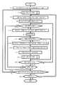
도 18은 실시예 2에 있어서의 손목 시계형 송수화 장치(104)의 제어부(98)의 기능을 나타낸 흐름도이다. 도 18의 플로우는, 도 6에 있어서의 실시예 1의 플로우와 공통되는 부분이 많으므로 대응하는 부분에는 동일 스텝 번호를 붙이고 필요가 없는 한 설명을 생략한다. 또한, 도 18의 플로우도, 연골 전도에 관한 기능을 중심으로 동작을 추출하여 도시하고 있고, 손목 시계형 송수화 장치(104)에는 통상의 손목 시계 기능을 비롯하여 도 18의 플로우에 표기하고 있지 않은 제어부(98)의 동작이 존재한다.18 is a flowchart showing the functions of the
도 18의 플로우는, 손목 시계형 송수화 장치(104)의 주전원의 온으로 시작하고, 스텝 S2에서 초기 구동 및 각 부 기능 체크를 행한다. 계속해서 스텝 S104에서 사용 준비 처리에 들어간다. 이 처리는, 손목 시계형 송수화 장치(104)가 장착되는 팔이나 조작부(100)의 방향에 대응하는 처리이며, 통상은 특정한 사용자에 의한 사용 개시 시점에 필요한 것이다. 또한, 후술하는 바와 같이, 표시의 방향 및 사용되는 연골 전도 진동원이 확정된 후에는, 특히 수동으로 설정 변경이 이루어지거나 설정된 상태에 대해 장착 모순이 자동 검출되지 않는 한 고정되어, 잘못하여 빈번히 변경되는 것을 방지한다. 스텝 S104에 있어서의 사용 준비 처리의 상세에 대해서는 후술한다.The flow of FIG. 18 starts with the main power supply of the wristwatch-
스텝 S104에 있어서의 사용 준비 처리가 종료되면 플로우는 스텝 S6으로 이행한다. 도 18의 스텝 S112는, 도 6의 스텝 S12에 대응하는 것이지만, 실시예 2에 있어서 연골 전도가 사용되지 않는 경우, 표면측 마이크(146)가 온된다. 한편, 도 18의 스텝 S118은, 도 6의 스텝 S18에 대응하는 것이지만, 실시예 2에 있어서, 연골 전도가 사용되는 경우, 이면측 마이크(147)가 온된다. 또한, 도 18에 있어서의 스텝 S122는, 도 6에 있어서의 스텝 S24, S26 및 S30을 통합하여 나타낸 것이다.When the use preparation process in step S104 ends, the flow advances to step S6. Step S112 in FIG. 18 corresponds to step S12 in FIG. 6, but when cartilage conduction is not used in the second embodiment, the
도 18에 있어서 스텝 S10 또는 스텝 S32로부터 스텝 S136으로 이행한 경우, 수동에 의한 표시의 방향 및 연골 전도 진동원을 변경하는 조작이 있었는지 여부, 및 확정되어 있던 표시의 방향 및 연골 전도 진동원에 대하여 모순되는 자동 검지가 있었는지 여부를 체크한다. 그리고 해당되면 스텝 S104로 되돌아가서, 사용 준비 처리를 재개한다. 한편, 스텝 S136에서 해당이 없으면, 스텝 S36으로 이행한다.In FIG. 18, when the process shifts from step S10 or step S32 to step S136, whether or not the manual display direction and the cartilage conduction vibration source have been changed and whether or not the determined display direction and the cartilage conduction vibration source are present. Check whether there was a contradictory automatic detection. If so, the flow returns to step S104 to resume the use preparation process. On the other hand, if there is no corresponding in step S136, the routine proceeds to step S36.
도 19는 도 18에 있어서의 스텝 S104의 사용 준비 처리의 상세를 나타내는 흐름도이다. 플로우가 시작되면, 스텝 S202에서 표시의 방향 및 사용하는 연골 전도 진동원에 대한 기존 설정의 유무를 체크한다. 그리고 기존 설정이 있으면 스텝 S204에서 그 내용을 호출하고 스텝 S206으로 이행한다. 한편, 스텝 S202에서 기존 설정이 검지되지 않으면 스텝 S208에서 표준 설정(도 12의 (A)의 설정)을 행하고 스텝 S206으로 이행한다.FIG. 19 is a flowchart showing details of the use preparation process of step S104 in FIG. 18. When the flow starts, it is checked in step S202 whether there is an existing setting for the direction of display and the cartilage conduction vibration source to be used. If there is an existing setting, the content is called in step S204, and the routine proceeds to step S206. On the other hand, if the existing setting is not detected in step S202, the standard setting (setting in Fig. 12A) is made in step S208, and the flow proceeds to step S206.
스텝 S206에서는, 표시의 방향 및 사용하는 연골 전도 진동원을 수동으로 설정하는 모드인지 여부를 체크한다. 수동 설정 모드가 아니면 자동 설정을 행하게 되므로 스텝 S210으로 이행하여 판단 이력의 유무를 체크한다. 도 19의 플로우에 들어간 시점(통상, 도 18의 스텝 S136에 있어서 장착 모순 자동 검지가 이루어지는 근거가 된 장착이 왼손인지 오른손인지의 판단 및 조작부(100)의 방향이 손등측인지 팔꿈치측인지의 판단)이 이루어진 시점에서는 판단 이력이 존재한다. 스텝 S210에서 판단 이력이 검지되지 않은 경우(통상, 새롭게 손목 시계형 송수화 장치(104)를 장착한 경우에 해당)에는 신규로 자동 판단 수순에 들어가기 때문에, 스텝 S212로 이행한다.In step S206, it is checked whether it is a mode which sets the direction of display and the cartilage conduction vibration source to be used manually. If it is not in the manual setting mode, automatic setting is performed. Therefore, the flow advances to step S210 to check the presence or absence of judgment history. When the flow enters the flow of FIG. 19 (usually, the determination of whether the mounting on which the mounting contradiction automatic detection is performed in step S136 of FIG. 18 is the left hand or the right hand, and whether the direction of the
먼저, 스텝 S212에서는, 사용자에 대하여 자동 판정을 행하기 위한 동작 안내를 개시한다. 여기서 안내되는 동작은, 구체적으로는, 중력 가속도 검지를 위해 손목 시계형 송수화 장치(104)를 장착한 팔을 내리는 것, 원심력 방향 검지를 위해 손목 시계형 송수화 장치(104)를 장착한 팔을 흔드는 것, 및 장착한 손의 판단을 위한 도 14의 (A)로부터 도 14의 (C)로의 동작(또는, 도 15의 (A)로부터 도 15의 (C)로의 동작)이지만, 이들은 모두 자연스러운 동작이기 때문에, 이와 같이 분석적으로 안내하는 것이 아니라, 장착 및 관찰을 위한 통상 동작으로서 간단하게 안내한다. 또한 안내하지 않아도 자연스럽게 취해지는 동작이기 때문에, 지시가 아니라 간단히 「장착 후, 표시 방향은 자동적으로 보정됩니다」라는 결과만의 안내로 해도 된다. 또한, 연골 전도 진동원의 선택은 엄지 손가락측에 오는 쪽이 정상적으로 선택되는 한, 사용자에게 특별히 안내할 필요는 없다.First, in step S212, operation guidance for automatic determination is performed for the user. The operation guided here is specifically, lowering the arm equipped with the
안내가 개시되면, 안내 도상에서 플로우는 스텝 S214로 진행하여, 가속도 센서(86)에 의해 조작부 중력 가속도의 데이터를 취득함과 함께 취득된 데이터와 함께 축적한다. 또한, 스텝 S216에서는, 가속도 센서(86)에 의해 조작부 원심력 방향의 데이터를 취득함과 함께 취득된 데이터와 함께 축적한다. 또한 스텝 S218에서는, 가속도 센서(86)에 의해 비틀림 가속도 발생의 데이터를 취득함과 함께 취득된 데이터와 함께 축적한다. 또한, 스텝 S220에서는, 이들의 축적 결과의 분석에 기초하여 판정되는 새로운 설정과 스텝 S204 또는 스텝 S208에 기초하는 구설정을 크로스 체크하고, 어느 것이 타당한지의 검증을 행한다. 스텝 S222에서는, 스텝 S214 내지 스텝 S222에 기초하여 판단을 행하기에 충분한 유의의 정보량의 취득이 완료되었는지 여부를 체크한다. 그리고 정보량이 신뢰성 있는 판단에 있어서 불충분하면 스텝 S214로 되돌아가서, 이하 스텝 S222에서 유의 정보량 취득 완료가 확인될 때까지 스텝 S214 내지 스텝 S222를 반복한다. 이 동안, 필요에 따라서 스텝 S212에서 개시된 안내를 계속한다. 한편, 스텝 S222에서 유의 정보량 취득 완료가 확인되면 스텝 S224로 이행하여, 장착된 팔 및 조작부(100)의 방향 판단을 행하고 스텝 S226으로 진행한다.When the guidance is started, the flow advances to step S214 on the guidance diagram, and the
한편, 스텝 S210에서 판단 이력이 있는 경우에는 그 이력에 기초하여 장착된 팔 및 조작부(100)의 방향의 판단을 행하고 스텝 S226으로 진행한다. 또한, 스텝 S206에서 수동 설정 모드가 검지된 경우에는 스텝 S228로 진행하여 수동 설정 방법의 안내를 행함과 함께 안내에 따른 사용자의 수동 설정 대응을 대기한다. 그리고 스텝 S228에 있어서의 수동 설정이 완료되면 스텝 S226으로 이행한다.On the other hand, if there is a judgment history in step S210, the direction of the mounted arm and the
스텝 S226에서는, 스텝 S224 경유, 또는 스텝 S210 경유, 또는 스텝 S228 경유로 행해진 설정에 따라서 표시의 상하 방향을 확정한다. 또한 스텝 S230에서는 사용하는 연골 전도 진동원을 확정한다. 또한, 이들 확정 스텝에 있어서, 관찰측으로부터 본 표시의 하측 방향과 요골측으로서 선택되는 연골 전도 진동원은 항상 일치하고 있다.In step S226, the up-down direction of a display is determined according to the setting made via step S224, via step S210, or via step S228. In addition, in step S230, the cartilage conduction vibration source to be used is determined. In addition, in these determination steps, the cartilage conduction vibration source selected as the downward direction of the display seen from the observation side and the radial side always coincides.
계속해서, 스텝 S232로 진행하여, 표시의 상하 방향 및 선택되는 연골 전도 진동원이 신규로 설정되었는지 또는 이전의 설정으로부터 변경되었는지를 체크한다. 그리고 어느 것에 해당되면 스텝 S234로 진행하여 사용법 표시 처리를 행하고 스텝 S236으로 이행한다. 한편, 스텝 S232에서 신규 설정 및 설정 변경이 모두 행해지지 않았을 때는, 번잡을 피하기 위해 사용법 표시 처리를 생략하고 바로 스텝 S236으로 이행한다.Subsequently, the flow advances to step S232 to check whether the up-down direction of the display and the cartilage conduction vibration source selected are newly set or changed from the previous settings. If any of the above is true, the flow advances to step S234 to perform usage display processing, and the flow advances to step S236. On the other hand, when neither new setting nor setting change is made in step S232, the usage display process is omitted to avoid the trouble, and the flow proceeds directly to step S236.
스텝 S236에서는, 장착 모순의 유무의 판단을 계속하도록 지시하고 플로우를 종료한다. 스텝 S236의 지시는, 손목 시계형 송수화 장치(104)의 사용 도중에 있어서 정기적으로 장착 모순의 체크를 행하여, 사용자의 변경 또는 동일 사용자의 사정에 의한 장착 팔 또는 조작부 방향의 변경에 대응하기 위해서이다. 이 지시에 따라서, 제어부(98)는 도 19의 스텝 S214 내지 스텝 S222를 일상적으로 수시로 실행하여, 장착 모순의 유무에 대응한다. 또한, 장착 모순이란, 예를 들어 도 12의 (A)의 상태로부터 도 12의 (B)의 상태로의 장착 팔의 변경이 행해져, 도 12의 (A)인 채로는 관찰 방향으로부터 보아 손목 시계형 송수화 장치(104)가 180도 회전되어 있음(조작부(100)의 방향에 주의)에도 불구하고, 손목 시계 표시부(30)의 상하가 도립됨과 함께, 진동하고 있는 연골 전도 진동원이 척골측으로 이동한 상태로 되어 있는 상태를 의미한다.In step S236, it is instructed to continue determination of the presence or absence of a mounting contradiction, and complete | finishes a flow. The instruction in step S236 is for periodically checking the mounting contradiction during the use of the wrist watch-
스텝 S236의 지시 실행에 의해, 도 18의 스텝 S136에서의 장착 모순 자동 검지가 가능해져, 스텝 S104로 이행함과 함께, 도 19에서 설명한 기능을 실행할 수 있다.By the instruction execution of step S236, the mounting contradiction automatic detection in step S136 of FIG. 18 becomes possible, it moves to step S104, and the function demonstrated in FIG. 19 can be performed.
이상의 실시예에 나타낸 다양한 특징의 실시는, 여기의 실시예에 한정되는 것은 아니고, 그 이점을 향수 가능한 한, 다른 실시예에서도 실시 가능하다. 또한, 다양한 특징은, 다양하게 변형하여 실시하는 것이 가능함과 함께, 각 실시예의 특징을 적절히 조합하여 실시하는 것이 가능하다.The implementation of the various features shown in the above embodiments is not limited to the embodiments herein, and may be implemented in other embodiments as long as the advantages thereof can be enjoyed. In addition, while various features can be modified and implemented, it is possible to implement by combining suitably the characteristics of each Example.
예를 들어, 실시예 2에 있어서, 제1 연골 전도 진동원(138) 및 제2 연골 전도 진동원(13) 중 한쪽을 선택적으로 진동시키는 것 대신에, 양자를 모두 진동시키도록 하여, 어느 것이 요골측에 오더라도 요골에 진동을 전달할 수 있도록 함과 함께, 척골측으로부터도 보강적으로 진동을 전달하도록 구성해도 된다.For example, in Example 2, instead of selectively vibrating either one of the first cartilage
또한, 실시예 2에 있어서, 오른손용 및 왼손용 중 어느 것으로도 전환 가능한 구성으로 하는 것 대신에, 도 11의 (A)에 도시한 상태의 손목 시계형 송수화 장치(104)를 왼손 전용의 손목 시계 상품으로서 제공함과 함께, 이것과는 별도로 도 11의 (B)에 도시한 상태의 손목 시계형 송수화 장치(104)를 오른손 전용의 손목 시계 상품으로서 제공하고, 어느 것을 구입할지를 사용자가 선택할 수 있도록 해도 된다.In addition, in Example 2, instead of setting it as the structure which can switch to either right hand or left hand, the wrist
또한, 실시예 2에 있어서, 연골 전도 진동원은 전환하지 않고 양쪽을 진동시키도록 하고, 전환은 표시의 상하 방향만으로 하는 것도 가능하다. 이와 같이 실시예 2에 있어서의 표시의 상하 자동 전환의 구성은, 연골 전도 진동원의 전환에 사용하지 않는 경우에도 유용하다.In addition, in Example 2, the cartilage conduction vibration source may be caused to vibrate both sides without switching, and the switching may be performed only in the vertical direction of the display. Thus, the structure of the automatic up-and-down switching of the display in Example 2 is useful also when it is not used for switching of a cartilage conduction vibration source.
<총괄><Overall>
이하에서는, 본 명세서 중에 개시되어 있는 다양한 실시예에 대하여 총괄적으로 설명한다.Hereinafter, various embodiments disclosed in the present specification will be described collectively.
본 명세서 중에 개시되어 있는 실시예는, 관찰 시에 있어서의 표시의 상하를 반전할 수 있는 표시부와, 장착 시에 요골의 원위단 근방 및 척골의 원위단에 접하는 부분에 각각 설치된 연골 전도용의 진동 전달부를 설치한 것을 특징으로 하는 수화 기능을 갖는 손목 시계를 제공한다. 구체적인 특징에 따르면, 장착 시에 손등측에 오는 위치에 조작부가 설치된다.The embodiments disclosed in the present specification provide vibrations for cartilage conduction provided in a display unit capable of inverting the upper and lower sides of the display at the time of observation, and in a portion near the distal end of the radial and in contact with the distal end of the ulna when mounted. Provided is a wristwatch having a sign language function, wherein the watch is provided. According to a specific feature, the operation portion is provided at a position coming to the back of the hand during mounting.
구체적인 특징에 따르면, 손목 시계는, 가속도 검지부와, 상기 가속도 검지부에 의해 검지되는 가속도에 기초하여 상기 표시부의 상하가 정립 상태로 되는 방향을 판단하는 판단부와, 상기 판단부의 판단에 기초하여 상기 표시부의 상하 방향을 결정함과 함께 그 판단에 반하는 상기 판단부에 의한 판단이 발생할 때까지 상기 상하 방향을 유지하는 표시 제어부를 갖는다. 보다 구체적인 특징에 따르면 상기 판단부는, 상기 조작부의 상하 방향과 상기 가속도 검지부에 의해 검지되는 가속도의 관계에 기초하여 상기 표시부의 상하를 정립 상태로 하는 방향을 판단한다. 다른 구체적인 특징에 따르면, 상기 판단부는, 상기 가속도 검지부에 의해 검지되는 중력 가속도의 평균값에 기초하여 상기 조작부가 상하 어느 것을 향하여 장착되어 있는지를 판단함과 함께, 상기 가속도 검지부에 의해 검지되는 비틀림 운동이 발생하는 순서와 방향의 평균값에 기초하여 손목 시계가 오른손에 장착되어 있는지 왼손에 장착되어 있는지를 판단하고, 그 조합에 기초하여 상기 표시부의 상하를 정립 상태로 하는 방향을 판단한다.According to a specific feature, the wristwatch includes an acceleration detection unit, a determination unit that determines a direction in which the upper and lower sides of the display unit are in a standing state based on the acceleration detected by the acceleration detection unit, and the display unit based on the determination of the determination unit. And a display control unit which determines the up and down direction of and maintains the up and down direction until a judgment by the determination unit contrary to the determination occurs. According to a more specific feature, the determination unit determines a direction in which the display unit is set up and down based on the relationship between the up and down direction of the operation unit and the acceleration detected by the acceleration detection unit. According to another specific feature, the determination unit determines whether the operation unit is mounted upward or downward based on the average value of the gravity acceleration detected by the acceleration detection unit, and the torsional motion detected by the acceleration detection unit It is judged whether the wristwatch is mounted on the right hand or the left hand on the basis of the average value of the order and the direction in which it occurs, and on the basis of the combination, the direction in which the display unit is set up and down is determined.
다른 구체적인 특징에 따르면, 손목 시계는 상기 표시부에 있어서의 상하의 반전에 연동하여, 연골 전도용의 진동 전달부 중 상기 요골의 원위단 근방에 오는 쪽을 선택적으로 진동시킨다. 다른 구체적인 특징에 따르면, 상기 요골의 원위단 근방 및 척골의 원위단에 접하는 부분에 각각 설치된 연골 전도용의 진동 전달부의 쌍방을 진동시킨다.According to another specific feature, the wristwatch selectively vibrates the one coming near the distal end of the radial among the vibration transmission units for cartilage conduction in conjunction with the up and down inversion of the display unit. According to another specific feature, vibrating both of the vibration transmitting portion for cartilage conduction, respectively provided in the vicinity of the distal end of the radial and in contact with the distal end of the ulna.
본 명세서 중에 개시되어 있는 실시예의 다른 특징에 따르면, 관찰 시에 있어서의 표시의 상하를 반전할 수 있는 표시부와, 가속도 검지부와, 상기 가속도 검지부에 의해 검지되는 가속도에 기초하여 상기 표시부의 상하가 정립 상태로 되는 방향을 판단하는 판단부와, 상기 판단부의 판단에 기초하여 상기 표시부의 상하 방향을 결정함과 함께 그 판단에 반하는 상기 판단부에 의한 판단이 발생할 때까지 상기 상하 방향을 유지하는 표시 제어부를 갖는 것을 특징으로 하는 수화 기능을 갖는 손목 시계가 제공된다. 구체적인 특징에 따르면, 손목 시계는, 장착 시에 손등측에 오는 위치에 설치되는 조작부를 갖고, 상기 판단부는, 상기 조작부의 상하 방향과 상기 가속도 검지부에 의해 검지되는 가속도의 관계에 기초하여 상기 표시부의 상하를 정립 상태로 하는 방향을 판단한다.According to another feature of the embodiments disclosed in the present specification, the upper and lower sides of the display unit are established based on the display unit capable of inverting the upper and lower sides of the display during observation, the acceleration detecting unit, and the acceleration detected by the acceleration detecting unit. A display control unit which determines a direction to be in a state and a vertical direction of the display unit based on the determination of the determination unit, and maintains the vertical direction until a determination by the determination unit contrary to the determination occurs. There is provided a wrist watch having a sign language function. According to a specific feature, the wristwatch has an operation unit provided at a position coming to the back of the hand when mounted, and the determination unit is based on the relationship between the up and down direction of the operation unit and the acceleration detected by the acceleration detection unit. The direction of making the up-and-down upright state is judged.
다른 구체적인 특징에 따르면, 상기 판단부는, 상기 가속도 검지부에 의해 검지되는 중력 가속도의 평균값에 기초하여 상기 조작부가 상하 어느 것을 향하여 장착되어 있는지를 판단함과 함께, 상기 가속도 검지부에 의해 검지되는 비틀림 운동이 발생하는 순서와 방향의 평균값에 기초하여 손목 시계가 오른손에 장착되어 있는지 왼손에 장착되어 있는지를 판단하고, 그 조합에 기초하여 상기 표시부의 상하를 정립 상태로 하는 방향을 판단한다. 다른 구체적인 특징에 따르면 상기 판단부는, 상기 가속도 검지부에 의해 검지되는 중력 가속도의 평균값에 기초하여 상기 조작부가 상하 어느 것을 향하여 장착되어 있는지를 판단함과 함께, 상기 가속도 검지부에 의해 검지되는 비틀림 운동이 발생하는 순서와 방향의 평균값에 기초하여 손목 시계가 오른손에 장착되어 있는지 왼손에 장착되어 있는지를 판단하고, 그 조합에 기초하여 상기 표시부의 상하를 정립 상태로 하는 방향을 판단한다.According to another specific feature, the determination unit determines whether the operation unit is mounted upward or downward based on the average value of the gravity acceleration detected by the acceleration detection unit, and the torsional motion detected by the acceleration detection unit It is judged whether the wristwatch is mounted on the right hand or the left hand on the basis of the average value of the order and the direction in which it occurs, and on the basis of the combination, the direction in which the display unit is set up and down is determined. According to another specific feature, the determination unit determines whether the operation unit is mounted upward or downward based on the average value of the gravity acceleration detected by the acceleration detection unit, and generates a torsional motion detected by the acceleration detection unit. On the basis of the order and the average value of the direction, it is determined whether the wristwatch is mounted on the right hand or the left hand, and based on the combination, the direction in which the display unit is set up and down is determined.
본 명세서 중에 개시되어 있는 실시예의 다른 특징에 따르면, 왼손에 채운 상태에서 표시부가 정립되어 보임과 함께 조작부가 손등측에 오는 왼손용 손목 시계와 오른손에 채운 상태에서 표시부가 정립되어 보임과 함께 조작부가 손등측에 오는 오른손용 손목 시계를 갖고, 상기 오른손용 손목 시계 및 왼손용 손목 시계 중 어느 것에도 장착 시에 요골의 원위단 근방에 접하는 부분에 연골 전도용의 진동 전달부를 배치한 것을 특징으로 하는 왼손용의 수화 기능을 갖는 손목 시계 및 오른손용의 수화 기능을 갖는 손목 시계가 제공된다.According to another feature of the embodiments disclosed in the present specification, the display is established in the state filled with the left hand wrist watch and the display is established in the state filled in the right hand with the display portion is established in the state filled with the left hand and the operation portion The left hand having a wrist watch for the right hand which comes to the back of the hand, and a vibration transmission unit for cartilage conduction is disposed at a part in contact with the vicinity of the distal end of the radial when attached to any of the wrist watch for the right hand and the wrist watch for the left hand. A wrist watch having a sign language function for a dragon and a wrist watch having a sign language function for a right hand are provided.
본 명세서 중에 개시되어 있는 실시예의 다른 특징에 따르면, 오른손에 채운 상태에서 정립되어 보이는 표시부와, 오른손에 채운 상태에서 손등측에 오는 조작부와, 오른손에 채웠을 때 오른손 요골의 원위단 근방에 접하는 부분에 배치되는 연골 전도용의 진동 전달부를 갖는 것을 특징으로 하는 오른손용의 수화 기능을 갖는 손목 시계가 제공된다.According to another feature of the embodiments disclosed in the present specification, the display portion is established in the state filled with the right hand, the operation portion coming to the back of the hand in the state filled with the right hand, and the portion in contact with the vicinity of the distal end of the radius of the right hand when filled in the right hand Provided is a wrist watch having a hydration function for a right hand, characterized by having a vibration transmitting portion for cartilage conduction disposed.
본 발명은 수화 기능을 갖는 손목 시계에 적용할 수 있다.The present invention can be applied to a wrist watch having a sign language function.
30 : 표시부
202a, 210a : 요골 원위단
204a, 212a : 척골 원위단
100, 100a, 100b : 조작부
86 : 가속도 검지부
98 : 표시 제어부
98 : 판단부30: display unit
202a, 210a: Distal radius
204a, 212a: ulnar distal end
100, 100a, 100b: control panel
86: acceleration detection unit
98: display control unit
98: judgment unit
Claims (10)
Translated fromKorean상기 표시부에 있어서의 상하의 반전에 연동하여, 연골 전도용의 진동 전달부 중 상기 요골의 원위단 근방에 오는 쪽을 선택적으로 진동시키고,
휴대 전화와의 통신기능을 갖고, 상기 휴대 전화의 송수화부로서 연계하는 것을 특징으로 하는 송수화 기능을 갖는 손목 시계.A display unit capable of reversing the display top and bottom at the time of observation, and a vibration transmission unit for cartilage conduction, respectively, provided at the portion near the distal end of the radial and the distal end of the ulna during mounting,
In conjunction with the up and down inversion of the display unit, the vibration transmitting unit for cartilage conduction is selectively vibrated in the vicinity of the distal end of the radial,
A wrist watch having a handset function, having a communication function with a mobile phone and cooperating as a handset of the mobile phone.
장착 시에 손등측에 오는 위치에 조작부를 설치한 것을 특징으로 하는 송수화 기능을 갖는 손목 시계.The method of claim 1,
A wrist watch having a handset function, wherein an operation unit is provided at a position coming to the back of the hand at the time of installation.
가속도 검지부와, 상기 가속도 검지부에 의해 검지되는 가속도에 기초하여 상기 표시부의 상하가 정립 상태로 되는 방향을 판단하는 판단부와, 상기 판단부의 판단에 기초하여 상기 표시부의 상하 방향을 결정함과 함께 그 판단에 반하는 상기 판단부에 의한 판단이 발생할 때까지 상기 상하 방향을 유지하는 표시 제어부를 갖는 것을 특징으로 하는 송수화 기능을 갖는 손목 시계.The method of claim 1,
A judging unit which determines an up and down direction of the display unit on the basis of an acceleration detecting unit, an acceleration detected by the acceleration detecting unit, and determines a vertical direction of the display unit based on the determination of the judging unit; A wrist watch having a handset function, characterized by having a display control unit for holding the vertical direction until a judgment by the determination unit contrary to the judgment.
장착 시에 손등측에 오는 위치에 조작부를 설치한 것을 특징으로 하는 송수화 기능을 갖는 손목 시계.The method of claim 3,
A wrist watch having a handset function, wherein an operation unit is provided at a position coming to the back of the hand at the time of installation.
상기 판단부는, 상기 조작부의 상하 방향과 상기 가속도 검지부에 의해 검지되는 가속도의 관계에 기초하여 상기 표시부의 상하를 정립 상태로 하는 방향을 판단하는 것을 특징으로 하는 송수화 기능을 갖는 손목 시계.The method of claim 4, wherein
And the determination unit determines a direction in which the display unit is placed up and down in the upright position based on the relationship between the up and down direction of the operation unit and the acceleration detected by the acceleration detection unit.
상기 판단부는, 상기 가속도 검지부에 의해 검지되는 중력 가속도의 평균값에 기초하여 상기 조작부가 상하 어느 것을 향하여 장착되어 있는지를 판단함과 함께, 상기 가속도 검지부에 의해 검지되는 비틀림 운동이 발생하는 순서와 방향의 평균값에 기초하여 손목 시계가 오른손의 손등측 또는 팔꿈치측에 장착되어 있는지 왼손의 손등측 또는 팔꿈치측에 장착되어 있는지를 판단하고, 그 조합에 기초하여 상기 표시부의 상하를 정립 상태로 하는 방향을 판단하는 것을 특징으로 하는 송수화 기능을 갖는 손목 시계.The method of claim 5,
The judging unit judges which of the operation units is mounted upward and downward based on the average value of the gravitational acceleration detected by the acceleration detecting unit, and the order and direction of the torsional motion detected by the acceleration detecting unit. On the basis of the average value, it is determined whether the wristwatch is mounted on the back of the right hand or elbow of the right hand or on the back of the left hand or elbow of the left hand, and based on the combination, the direction of setting the top and bottom of the display part in the upright position is determined. Wristwatch having a handset function, characterized in that.
상기 표시부는 텔레비전 전화의 화면 표시도 가능하여, 텔레비전 전화가 가능한 송수화 기능을 갖는 손목 시계.The method of claim 1,
The display part is a wrist watch having a handset function capable of displaying a screen of a television telephone and enabling a television telephone.
상기 판단부의 표시부의 자세 판단 결과에 기초하여, 대화용 마이크의 지향성을 항상 조작자 측으로 전환하는 기능을 갖는 송수화 기능을 갖는 손목 시계.The method of claim 3,
A wrist watch having a handset function having a function of always switching the directivity of the dialogue microphone toward the operator side based on the result of the attitude judgment of the display unit of the determination unit.
상기 연골 전도용의 진동 전달부는, 상기 휴대 전화의 착신 바이브레이터로서의 기능을 갖는 송수화 기능을 갖는 손목 시계.The method of claim 1,
The vibration transmission unit for cartilage conduction is a wrist watch having a handset function having a function as an incoming vibrator of the mobile telephone.
Applications Claiming Priority (3)
| Application Number | Priority Date | Filing Date | Title |
|---|---|---|---|
| JPJP-P-2015-182592 | 2015-09-16 | ||
| JP2015182592AJP6551929B2 (en) | 2015-09-16 | 2015-09-16 | Watch with earpiece function |
| PCT/JP2016/076494WO2017047501A1 (en) | 2015-09-16 | 2016-09-08 | Wristwatch with receiver function |
Related Parent Applications (1)
| Application Number | Title | Priority Date | Filing Date |
|---|---|---|---|
| KR1020187006763ADivisionKR102017755B1 (en) | 2015-09-16 | 2016-09-08 | Wristwatch with sign language |
Publications (2)
| Publication Number | Publication Date |
|---|---|
| KR20190104240A KR20190104240A (en) | 2019-09-06 |
| KR102083769B1true KR102083769B1 (en) | 2020-03-02 |
Family
ID=58289205
Family Applications (2)
| Application Number | Title | Priority Date | Filing Date |
|---|---|---|---|
| KR1020187006763AActiveKR102017755B1 (en) | 2015-09-16 | 2016-09-08 | Wristwatch with sign language |
| KR1020197025296AActiveKR102083769B1 (en) | 2015-09-16 | 2016-09-08 | Wristwatch with receiver function |
Family Applications Before (1)
| Application Number | Title | Priority Date | Filing Date |
|---|---|---|---|
| KR1020187006763AActiveKR102017755B1 (en) | 2015-09-16 | 2016-09-08 | Wristwatch with sign language |
Country Status (8)
| Country | Link |
|---|---|
| US (1) | US10795321B2 (en) |
| EP (1) | EP3336616B1 (en) |
| JP (1) | JP6551929B2 (en) |
| KR (2) | KR102017755B1 (en) |
| CN (1) | CN108027588B (en) |
| HK (1) | HK1255532A1 (en) |
| TW (1) | TWI645270B (en) |
| WO (1) | WO2017047501A1 (en) |
Families Citing this family (21)
| Publication number | Priority date | Publication date | Assignee | Title |
|---|---|---|---|---|
| KR101604521B1 (en) | 2010-12-27 | 2016-03-17 | 로무 가부시키가이샤 | Transmitter/receiver unit and receiver unit |
| TWI660618B (en) | 2012-01-20 | 2019-05-21 | 日商精良股份有限公司 | Mobile phone |
| TWI724317B (en) | 2012-06-29 | 2021-04-11 | 日商精良股份有限公司 | Headphones and stereo headphones |
| WO2014143776A2 (en) | 2013-03-15 | 2014-09-18 | Bodhi Technology Ventures Llc | Providing remote interactions with host device using a wireless device |
| TWI647608B (en) | 2014-07-21 | 2019-01-11 | 美商蘋果公司 | Remote user interface |
| WO2016036603A1 (en)* | 2014-09-02 | 2016-03-10 | Apple Inc. | Reduced size configuration interface |
| CN107113481B (en) | 2014-12-18 | 2019-06-28 | 株式会社精好 | Cartilage conduction hearing device using electromagnetic vibration unit and electromagnetic vibration unit |
| EP3323567B1 (en) | 2015-07-15 | 2020-02-12 | FINEWELL Co., Ltd. | Robot and robot system |
| JP6551929B2 (en) | 2015-09-16 | 2019-07-31 | 株式会社ファインウェル | Watch with earpiece function |
| US10778824B2 (en) | 2016-01-19 | 2020-09-15 | Finewell Co., Ltd. | Pen-type handset |
| US10739857B2 (en)* | 2018-04-21 | 2020-08-11 | Dale Kazdan | Wearable tracking computer |
| JP2020053948A (en) | 2018-09-28 | 2020-04-02 | 株式会社ファインウェル | Hearing device |
| US10678334B1 (en)* | 2018-11-30 | 2020-06-09 | Facebook Technologies, Llc | Systems and methods for providing substantially orthogonal movement of a device about a user's body part |
| JP6921338B2 (en) | 2019-05-06 | 2021-08-18 | アップル インコーポレイテッドApple Inc. | Limited operation of electronic devices |
| DK201970533A1 (en) | 2019-05-31 | 2021-02-15 | Apple Inc | Methods and user interfaces for sharing audio |
| CN112399296B (en)* | 2019-08-19 | 2023-05-12 | Oppo广东移动通信有限公司 | Wearable device |
| JP2022017706A (en)* | 2020-07-14 | 2022-01-26 | 株式会社東海理化電機製作所 | Wearable terminal, gesture method display system and display method for gesture method |
| KR20220077294A (en) | 2020-12-01 | 2022-06-09 | 현대모비스 주식회사 | Driver assistance system and method |
| IT202000029999A1 (en)* | 2020-12-04 | 2022-06-04 | Deed S R L | WEARABLE DEVICE FOR PERFORMING AUDIO COMMUNICATION THROUGH BONE CONDUCTION AND RELATED SYSTEM AND METHOD |
| CN112711334A (en)* | 2021-01-15 | 2021-04-27 | 维沃移动通信有限公司 | Screen control method and device and electronic equipment |
| US12386428B2 (en) | 2022-05-17 | 2025-08-12 | Apple Inc. | User interfaces for device controls |
Citations (5)
| Publication number | Priority date | Publication date | Assignee | Title |
|---|---|---|---|---|
| US20050276164A1 (en) | 2004-06-12 | 2005-12-15 | Scott Amron | Watch adapted to rotate a displayed image so as to appear in a substantially constant upright orientation |
| KR101398946B1 (en) | 2013-06-25 | 2014-05-27 | 서울시립대학교 산학협력단 | Apparatus, method and recording medium for control of smart watch |
| JP2015139132A (en) | 2014-01-23 | 2015-07-30 | 株式会社ファインウェル | Notification device |
| WO2015122879A1 (en) | 2014-02-11 | 2015-08-20 | Bodhi Technology Ventures Llc | Detecting the limb wearing a wearable electronic device |
| KR102017755B1 (en)* | 2015-09-16 | 2019-09-04 | 파인웰 씨오., 엘티디 | Wristwatch with sign language |
Family Cites Families (608)
| Publication number | Priority date | Publication date | Assignee | Title |
|---|---|---|---|---|
| US2045404A (en) | 1933-05-24 | 1936-06-23 | Sonotone Corp | Piezoelectric vibrator device |
| JPS518161B1 (en) | 1970-05-07 | 1976-03-15 | ||
| JPS5246695B2 (en) | 1973-06-15 | 1977-11-26 | ||
| JPS5194220A (en) | 1975-02-15 | 1976-08-18 | Denkishingo shindohenkansochi | |
| JPS5236894A (en) | 1975-09-16 | 1977-03-22 | Hidetaka Takeda | Ear plug |
| JPS5588497A (en) | 1978-12-25 | 1980-07-04 | Matsushita Electric Ind Co Ltd | Ear receiver |
| JPS5617780A (en) | 1979-07-25 | 1981-02-19 | Mitsubishi Heavy Ind Ltd | Hatch cover device |
| JPS5689086A (en)* | 1979-12-20 | 1981-07-20 | Seiko Epson Corp | Display device for digital watch |
| JPS5690018A (en) | 1979-12-21 | 1981-07-21 | Ihara Chem Ind Co Ltd | Preparation of organic bromide |
| US4351166A (en) | 1980-11-10 | 1982-09-28 | Juliette Belin | Ring |
| JPS57162611A (en) | 1981-03-31 | 1982-10-06 | Kurita Water Ind Ltd | Flocculation reacting tank |
| JPS58182398A (en) | 1982-04-19 | 1983-10-25 | Takeshi Yoshii | Magnetic bone conduction and eardrum oscillation microphone in common use of transmission and reception |
| JPS60116800A (en) | 1983-11-29 | 1985-06-24 | Naganoken | Degreasing and activation method using high-speed current reversal electrolysis |
| GB2162342B (en)* | 1984-07-25 | 1987-09-30 | Loughran Edward | Alarm time-pieces |
| JPS62208680A (en) | 1986-03-07 | 1987-09-12 | Murata Mfg Co Ltd | Laminar bymorph |
| JPS63115728A (en) | 1986-11-05 | 1988-05-20 | Toyota Motor Corp | Manufacture of core material of steering wheel |
| US4736250A (en) | 1986-11-28 | 1988-04-05 | Tektronix, Inc. | Digital camera frame capture circuit |
| JPS63140753A (en) | 1986-11-30 | 1988-06-13 | Chuo Denki Kogyo Kk | Production of porous heat radiator |
| USRE34525E (en) | 1987-06-24 | 1994-02-01 | Lazzaroni; John J. | Motorcycle helmet microphone mount and plug mount |
| FR2629624B1 (en) | 1988-04-05 | 1990-11-16 | Framatome Sa | METHOD FOR DETERMINING AND EVALUATING THE RETURN CAPACITY OF A PRESSURIZED WATER NUCLEAR REACTOR |
| JPH0262199A (en) | 1988-08-02 | 1990-03-02 | B Shriver Simeon | Bone-conductive sound catching device and method |
| US5125032A (en) | 1988-12-02 | 1992-06-23 | Erwin Meister | Talk/listen headset |
| JPH02182098A (en) | 1989-01-07 | 1990-07-16 | Hiroshi Osada | Headphone for stereophonic |
| JP2770389B2 (en) | 1989-03-20 | 1998-07-02 | ソニー株式会社 | Wireless headphone system |
| JPH0329424A (en) | 1989-06-27 | 1991-02-07 | Oki Electric Ind Co Ltd | Echo canceller circuit for hand-free telephone call |
| JPH03117995A (en) | 1989-09-29 | 1991-05-20 | Mitsubishi Electric Corp | Color signal contour correction device |
| JPH0490298A (en) | 1990-08-02 | 1992-03-24 | Matsushita Electric Ind Co Ltd | Hearing aid |
| JPH04303815A (en) | 1991-03-30 | 1992-10-27 | I Utsudo:Kk | Temple of psectacles body |
| JP3235865B2 (en) | 1991-06-03 | 2001-12-04 | パイオニア株式会社 | Ear speakers |
| US5956682A (en) | 1991-06-06 | 1999-09-21 | Lj Laboratories, Llc | Picture frame with associated audio messages and position sensitive or speech recognition device |
| JPH0541297A (en) | 1991-07-31 | 1993-02-19 | Ishikawajima Harima Heavy Ind Co Ltd | Vacuum exhaust device for SOR device |
| JP2894035B2 (en) | 1991-09-18 | 1999-05-24 | 日産自動車株式会社 | Active noise control device |
| JPH05183618A (en) | 1991-12-27 | 1993-07-23 | Sony Corp | Telephone set |
| US5295193A (en) | 1992-01-22 | 1994-03-15 | Hiroshi Ono | Device for picking up bone-conducted sound in external auditory meatus and communication device using the same |
| JPH05292167A (en) | 1992-04-13 | 1993-11-05 | Sony Corp | Telephone set |
| US5323468A (en) | 1992-06-30 | 1994-06-21 | Bottesch H Werner | Bone-conductive stereo headphones |
| JP3101842B2 (en) | 1992-07-06 | 2000-10-23 | アツデン株式会社 | Directional microphone device |
| JPH0739150A (en) | 1993-07-16 | 1995-02-07 | Nec Field Service Ltd | Power supply |
| HU212134B (en) | 1993-07-27 | 1998-06-29 | László Holakovszky | An image, preferably a TV-imaging device, attached to glasses |
| JP2698320B2 (en) | 1993-08-31 | 1998-01-19 | 日本電信電話株式会社 | Permanent input system, Permanent intention communication system, Permanent music keyboard system, Permanent Braille input / output system |
| JPH07107146A (en) | 1993-10-05 | 1995-04-21 | Mitsubishi Electric Corp | Cordless telephone device using bone conduction earphone microphone |
| JPH07131268A (en) | 1993-10-29 | 1995-05-19 | Casio Comput Co Ltd | Telephone |
| JP3907215B2 (en) | 1994-01-18 | 2007-04-18 | 富士通テン株式会社 | Noise control device |
| JP3003950U (en) | 1994-05-09 | 1994-11-01 | 株式会社京浜特殊印刷 | Amplifier for learning foreign language |
| CN2198618Y (en) | 1994-05-19 | 1995-05-24 | 刘瓒澄 | Stereo TV glass |
| JPH0833026A (en) | 1994-07-15 | 1996-02-02 | Nitsuko Corp | Battery support for radio equipment |
| JPH0879338A (en) | 1994-08-30 | 1996-03-22 | Sanyo Electric Co Ltd | Portable telephone set |
| JP3009206U (en) | 1994-09-19 | 1995-04-04 | リオン電子株式会社 | Piezoelectric drive type transport device |
| JPH0890986A (en) | 1994-09-28 | 1996-04-09 | Pilot Corp:The | Writing utensil |
| JPH08102780A (en) | 1994-09-30 | 1996-04-16 | Nippon Telegr & Teleph Corp <Ntt> | Hearing aid for telephone |
| JPH08111703A (en) | 1994-10-07 | 1996-04-30 | Matsushita Electric Ind Co Ltd | Mobile radio telephone |
| JP3418808B2 (en) | 1995-02-27 | 2003-06-23 | 富士通株式会社 | Mobile communication terminals |
| JPH08242273A (en) | 1995-03-02 | 1996-09-17 | Tdk Corp | Incoming call vibrator |
| JPH08256080A (en) | 1995-03-16 | 1996-10-01 | Sharp Corp | Portable information equipment |
| JPH0923256A (en) | 1995-07-07 | 1997-01-21 | Oki Electric Ind Co Ltd | Structure for telephone set |
| KR0161916B1 (en) | 1995-07-14 | 1998-12-01 | 구자홍 | Circuit of correcting carrier frequency error in bs receiver |
| CN1141856A (en) | 1995-08-02 | 1997-02-05 | 楚树湘 | Photoelectric sculpturing method |
| US5686882A (en)* | 1996-02-20 | 1997-11-11 | Giani; Sandra M. | Silent alarm band |
| US5687244A (en) | 1996-03-28 | 1997-11-11 | Stanton Magnetics, Inc. | Bone conduction speaker and mounting system |
| JP2888287B2 (en) | 1996-07-25 | 1999-05-10 | 日本電気株式会社 | Telephone |
| AU3358297A (en) | 1996-07-29 | 1998-02-20 | Nihon Belbon Seiki | Wristwatchlike telephone set |
| JPH1065996A (en) | 1996-08-23 | 1998-03-06 | Olympus Optical Co Ltd | Head wearable display device |
| KR100229033B1 (en) | 1996-09-24 | 1999-11-01 | 윤종용 | Apparatus and method for saving power in a nonvolatile memory |
| JP3172827B2 (en) | 1996-10-28 | 2001-06-04 | 正雄 遠藤 | Sound recognition method and apparatus for hearing impaired |
| JPH10200608A (en) | 1997-01-10 | 1998-07-31 | Shuichi Osawa | Portable telephone set |
| KR19980063410A (en) | 1997-08-19 | 1998-10-07 | 양승택 | Telephone with handcuffs for both bone and airway hearing |
| JPH11112672A (en) | 1997-09-30 | 1999-04-23 | Mitsubishi Electric Corp | Multipoint communication device |
| JPH11163980A (en) | 1997-12-01 | 1999-06-18 | Daisan Kikaku Kk | Incoming call sensor accessory for portable telephone |
| JP2589555Y2 (en) | 1997-12-04 | 1999-01-27 | 日本電気株式会社 | Battery storage structure |
| JP3050147U (en) | 1997-12-24 | 1998-06-30 | 嘉正 平田 | Simplified mobile phone for the hearing impaired |
| JP3067762B2 (en) | 1998-03-18 | 2000-07-24 | 日本電信電話株式会社 | Wearable communication device |
| EP0951883B1 (en) | 1998-03-18 | 2005-07-27 | Nippon Telegraph and Telephone Corporation | Wearable communication device with bone conduction transducer |
| JP3298578B2 (en) | 1998-03-18 | 2002-07-02 | 日本電信電話株式会社 | Wearable command input device |
| JPH11298595A (en) | 1998-04-10 | 1999-10-29 | Mitsubishi Electric Corp | Communication device |
| JP3207158B2 (en) | 1998-05-11 | 2001-09-10 | 株式会社テムコジャパン | Headset with bone-conducting speaker and microphone |
| JPH11352138A (en) | 1998-06-04 | 1999-12-24 | Seiko Instruments Inc | Magnetic force microscope |
| JP2000013294A (en) | 1998-06-24 | 2000-01-14 | Nippon Telegr & Teleph Corp <Ntt> | Wireless handset |
| JP3160714B2 (en) | 1998-07-08 | 2001-04-25 | 株式会社シコー技研 | Portable wireless communication device |
| US6463157B1 (en) | 1998-10-06 | 2002-10-08 | Analytical Engineering, Inc. | Bone conduction speaker and microphone |
| US6950126B1 (en) | 1998-11-19 | 2005-09-27 | Nikon Corporation | Camera capable of communicating with other communication device |
| JP4281182B2 (en) | 1998-11-19 | 2009-06-17 | 株式会社ニコン | Camera with communication function |
| JP3623127B2 (en) | 1998-12-25 | 2005-02-23 | 松下電器産業株式会社 | Headphone device |
| JP3064055U (en) | 1999-02-08 | 1999-12-14 | 照美 森屋 | Thin mobile phone with an appropriate distance between earpiece and mouthpiece |
| JP3537128B2 (en) | 1999-04-01 | 2004-06-14 | 日本電信電話株式会社 | headphone |
| JP2000324217A (en) | 1999-05-07 | 2000-11-24 | Ntt Docomo Inc | Sound information transmission device in portable device and portable device |
| JP2000339793A (en) | 1999-05-28 | 2000-12-08 | Sony Corp | Reproducing device |
| JP3322849B2 (en) | 1999-06-03 | 2002-09-09 | 株式会社テムコジャパン | Mobile communication device with bone conduction speaker |
| JP3066305U (en) | 1999-08-02 | 2000-02-18 | 博次 高野 | Hearing aid |
| JP4142836B2 (en) | 1999-10-29 | 2008-09-03 | 株式会社インターナショナル インテリジェント インフォメーション | Penphone PDA |
| JP3750910B2 (en) | 1999-12-13 | 2006-03-01 | セイコーインスツル株式会社 | Information processing apparatus and information processing method |
| JP3541765B2 (en) | 1999-12-21 | 2004-07-14 | 日本電気株式会社 | Videophone equipment |
| JP2003529976A (en) | 2000-01-07 | 2003-10-07 | アサナス ルイス | Machine-acoustic transducer and multimedia flat film speaker |
| JP3070222U (en) | 2000-01-11 | 2000-07-28 | 勲 伊藤 | Bone conduction receiver |
| JP2001287183A (en) | 2000-01-31 | 2001-10-16 | Matsushita Electric Works Ltd | Automatic conveyance robot |
| JP2001268211A (en) | 2000-03-21 | 2001-09-28 | Xanavi Informatics Corp | Hands-free device for telephone |
| JP3556151B2 (en) | 2000-05-09 | 2004-08-18 | 株式会社テムコジャパン | Transmitter / receiver using bone conduction speaker |
| JP2001333161A (en) | 2000-05-18 | 2001-11-30 | Nec Corp | Portable terminal |
| JP2001339504A (en) | 2000-05-26 | 2001-12-07 | Sharp Corp | Wireless communication equipment |
| JP2001352395A (en) | 2000-06-07 | 2001-12-21 | Sony Corp | Mobile terminal |
| EP1292913B1 (en) | 2000-06-12 | 2005-08-17 | United Parcel Service Of America, Inc. | System and method for real-time tracking of packages |
| CN1193570C (en) | 2000-06-21 | 2005-03-16 | 精工爱普生株式会社 | Coordinated processing of incoming mobile phones and radios |
| JP2002084575A (en) | 2000-06-21 | 2002-03-22 | Seiko Epson Corp | Wearable wireless communication device, mobile phone device, control method thereof, control method of wireless communication system, control program, and recording medium |
| JP2002016720A (en) | 2000-06-29 | 2002-01-18 | Matsushita Electric Ind Co Ltd | Information communication equipment |
| JP4626019B2 (en) | 2000-07-05 | 2011-02-02 | 株式会社ニコン | Glasses frame |
| US20040105566A1 (en) | 2000-07-27 | 2004-06-03 | International Business Machines Corporation | Body set type speaker unit |
| JP2002036158A (en) | 2000-07-27 | 2002-02-05 | Yamaha Motor Co Ltd | Electronic appliance having autonomous function |
| JP3745602B2 (en) | 2000-07-27 | 2006-02-15 | インターナショナル・ビジネス・マシーンズ・コーポレーション | Body set type speaker device |
| JP2002041411A (en) | 2000-07-28 | 2002-02-08 | Nippon Telegr & Teleph Corp <Ntt> | Text-to-speech robot, control method thereof, and recording medium storing text-to-speech robot control program |
| JP4059618B2 (en) | 2000-07-31 | 2008-03-12 | 株式会社ケンウッド | Communication terminal |
| JP3949912B2 (en) | 2000-08-08 | 2007-07-25 | 株式会社エヌ・ティ・ティ・ドコモ | Portable electronic device, electronic device, vibration generator, notification method by vibration and notification control method |
| US6754359B1 (en) | 2000-09-01 | 2004-06-22 | Nacre As | Ear terminal with microphone for voice pickup |
| AU2001282620A1 (en) | 2000-09-04 | 2002-03-22 | Applied Electronics Laboratories, Inc. | Display window having voice input/output function |
| JP3831190B2 (en) | 2000-10-02 | 2006-10-11 | 株式会社エヌ・ティ・ティ・ドコモ | Actuator support device and body-worn type transmission / reception device including the actuator support device |
| JP3312902B2 (en) | 2000-11-24 | 2002-08-12 | 株式会社テムコジャパン | Mobile phone attachment for the hearing impaired |
| JP2002171321A (en) | 2000-11-30 | 2002-06-14 | Toshiba Corp | Mobile wireless terminal |
| JP2002223475A (en) | 2001-01-25 | 2002-08-09 | Nec Telecom Syst Ltd | Mobile communication terminal, wrist watch and call reception system, and call reception method |
| TW510139B (en) | 2001-01-26 | 2002-11-11 | Kirk Acoustics As | An electroacoustic transducer and a coil and a magnet circuit therefor |
| JP3404384B2 (en) | 2001-02-09 | 2003-05-06 | 太平洋セメント株式会社 | Piezoelectric transformer inverter |
| JP2002262377A (en) | 2001-02-28 | 2002-09-13 | Taiyo Yuden Co Ltd | Bone conduction pickup element and its unit |
| JP2002295696A (en) | 2001-03-29 | 2002-10-09 | Kitamura Valve Seizo Kk | Trunnion type ball valve |
| US7616771B2 (en) | 2001-04-27 | 2009-11-10 | Virginia Commonwealth University | Acoustic coupler for skin contact hearing enhancement devices |
| JP3532535B2 (en) | 2001-05-31 | 2004-05-31 | 株式会社テムコジャパン | Handset device |
| JP2002368839A (en) | 2001-06-06 | 2002-12-20 | Matsushita Electric Ind Co Ltd | Telephone and method of correcting audio signal frequency of the telephone |
| JP3763570B2 (en) | 2001-06-28 | 2006-04-05 | 松下電器産業株式会社 | Speaker system, portable terminal device, and electronic device |
| JP2003101625A (en) | 2001-07-05 | 2003-04-04 | Mieko Tsuyusaki | Portable telephone set, and telephone set |
| WO2003005485A1 (en) | 2001-07-05 | 2003-01-16 | Eta Sa Manufacture Horlogere Suisse | Irst-worm electronic instrument with antenna |
| JP2003032343A (en) | 2001-07-17 | 2003-01-31 | Mitsubishi Electric Corp | Mobile phone |
| JP2003032768A (en) | 2001-07-19 | 2003-01-31 | Matsushita Electric Ind Co Ltd | headphone |
| JP3699018B2 (en) | 2001-07-25 | 2005-09-28 | 埼玉日本電気株式会社 | Automatic volume control device for telephone |
| JP3834494B2 (en) | 2001-09-19 | 2006-10-18 | 株式会社ケンウッド | Piezoelectric speaker device |
| JP2003103220A (en) | 2001-09-28 | 2003-04-08 | Nec Tokin Corp | Living body conductive actuator |
| JP2003173375A (en) | 2001-09-28 | 2003-06-20 | Toshiba Corp | Life management terminal device, life management method and life management system |
| JP2003174495A (en) | 2001-09-28 | 2003-06-20 | Nec Corp | Folding portable information terminal |
| JP2003111175A (en) | 2001-10-01 | 2003-04-11 | Yukio Masuda | Speech transmission and receiving system |
| JP2003125473A (en) | 2001-10-10 | 2003-04-25 | Nec Tokin Corp | Housing case vibration piezoelectric actuator and portable electronic apparatus |
| JP4313560B2 (en) | 2001-10-31 | 2009-08-12 | パナソニック株式会社 | mobile phone |
| JP3678694B2 (en) | 2001-11-02 | 2005-08-03 | Necビューテクノロジー株式会社 | Interactive terminal device, call control method thereof, and program thereof |
| JP2003145048A (en) | 2001-11-16 | 2003-05-20 | Nec Tokin Corp | Bone conduction vibrating actuator and portable electronic apparatus |
| JP2003169115A (en) | 2001-11-29 | 2003-06-13 | Kyocera Corp | Foldable mobile phone |
| US6639987B2 (en) | 2001-12-11 | 2003-10-28 | Motorola, Inc. | Communication device with active equalization and method therefor |
| JP2003188985A (en) | 2001-12-20 | 2003-07-04 | Matsushita Electric Ind Co Ltd | Wireless headset, helmet using the same, internet telephone system, vehicle hands-free system, communication system, credit processing system, and cash service system |
| JP4202640B2 (en) | 2001-12-25 | 2008-12-24 | 株式会社東芝 | Short range wireless communication headset, communication system using the same, and acoustic processing method in short range wireless communication |
| US20030119566A1 (en) | 2001-12-26 | 2003-06-26 | E-Lead Electronic Co., Ltd. | Hand-free device equipped with expansion function modules |
| JP2003211087A (en) | 2002-01-22 | 2003-07-29 | Nec Tokin Corp | Vibration actuator and display device |
| JP2003218989A (en) | 2002-01-24 | 2003-07-31 | Fdk Corp | Incoming device |
| US20030174856A1 (en) | 2002-01-25 | 2003-09-18 | Leif Johannsen | Flexible diaphragm with integrated coil |
| DE60324665D1 (en) | 2002-01-25 | 2008-12-24 | Sonion Horsens As | FLEXIBLE MEMBRANE WITH INTEGRATED COIL |
| JP4203246B2 (en) | 2002-03-14 | 2008-12-24 | 京セラ株式会社 | Portable communication device |
| JP2003274470A (en) | 2002-03-19 | 2003-09-26 | Denso Corp | Bone conduction voice vibration detecting element, manufacturing method of bone conduction voice vibration detecting element, and voice recognition system |
| GB0207732D0 (en) | 2002-04-03 | 2002-05-15 | Ttpcomm Ltd | Wireless communication terminals |
| JP2003300015A (en) | 2002-04-05 | 2003-10-21 | Nec Tokin Corp | Method for driving vibration actuator, and portable device |
| JP2003319022A (en) | 2002-04-26 | 2003-11-07 | Sanyo Electric Co Ltd | Portable telephone device |
| WO2003093950A2 (en) | 2002-05-06 | 2003-11-13 | David Goldberg | Localized audio networks and associated digital accessories |
| JP2003348208A (en) | 2002-05-29 | 2003-12-05 | Temuko Japan:Kk | Portable telephone set provided with bone-conduction speaker |
| JP3090729U (en) | 2002-06-13 | 2002-12-26 | 蕃夫 鈴木 | Pen-type separate handset for writing |
| JP3535143B2 (en) | 2002-07-01 | 2004-06-07 | 日立マクセル株式会社 | Ear-mounted sound information transmitter |
| WO2004012068A1 (en) | 2002-07-25 | 2004-02-05 | Sonion Horsens A/S | Mobile handset and assembly having multi-loudspeaker system |
| CN1720763B (en) | 2002-07-26 | 2013-06-12 | 奥克利有限公司 | Glasses |
| JP3985094B2 (en) | 2002-07-30 | 2007-10-03 | 透 加藤 | Bone-conduction speaker device and communication system |
| JP3937982B2 (en) | 2002-08-29 | 2007-06-27 | ソニー株式会社 | INPUT / OUTPUT DEVICE AND ELECTRONIC DEVICE HAVING INPUT / OUTPUT DEVICE |
| AU2003261871A1 (en) | 2002-08-30 | 2004-03-19 | Asahi Kasei Kabushiki Kaisha | Microphone and communication interface system |
| JP2004166174A (en) | 2002-09-20 | 2004-06-10 | Junichi Suzuki | External auditory meatus insertion type bone conduction receiver, and external auditory meatus insertion type bone conduction hearing aid |
| JP3889342B2 (en) | 2002-10-03 | 2007-03-07 | 日本電信電話株式会社 | Wearable communication device |
| WO2004034734A1 (en) | 2002-10-08 | 2004-04-22 | Nec Corporation | Array device and portable terminal |
| NZ539237A (en) | 2002-10-09 | 2006-11-30 | Univ East Carolina | Frequency altered feedback for treating non-stuttering pathologies |
| JP3875178B2 (en) | 2002-11-05 | 2007-01-31 | 日本電信電話株式会社 | Headphone device |
| JP4244130B2 (en) | 2002-11-07 | 2009-03-25 | ソニー・エリクソン・モバイルコミュニケーションズ株式会社 | Mobile terminal system and mobile terminal device |
| JP4712294B2 (en) | 2002-11-08 | 2011-06-29 | 株式会社半導体エネルギー研究所 | Display device |
| SG143934A1 (en) | 2002-11-08 | 2008-07-29 | Semiconductor Energy Lab | Display appliance |
| JP2004173018A (en) | 2002-11-20 | 2004-06-17 | Toshiba Life Engineering Kk | Communication system for helmet |
| JP2004187031A (en) | 2002-12-04 | 2004-07-02 | Temuko Japan:Kk | Mobile phone using bone conduction speaker |
| JP2004190699A (en) | 2002-12-06 | 2004-07-08 | Sony Corp | Clip and clip clamping method |
| CN2575916Y (en) | 2002-12-13 | 2003-09-24 | 深圳市天霆实业发展有限公司 | Digital distributing frame for communication |
| JP2004205839A (en) | 2002-12-25 | 2004-07-22 | Fuji Iryoki:Kk | Hearing aid |
| JP4069294B2 (en) | 2002-12-26 | 2008-04-02 | Tdk株式会社 | Earphone, audio transmission device |
| JP2004266321A (en) | 2003-01-22 | 2004-09-24 | Hitachi Maxell Ltd | Ear-mounted communication device |
| JP2004233316A (en) | 2003-02-03 | 2004-08-19 | Matsushita Electric Ind Co Ltd | Clock with wireless communication function |
| JP2004252626A (en) | 2003-02-19 | 2004-09-09 | Tokyo Shinyu:Kk | Message transmission method to information terminal device |
| US7409234B2 (en) | 2003-03-07 | 2008-08-05 | Cardo Systems, Inc. | Wireless communication headset with exchangeable attachments |
| JP4121398B2 (en) | 2003-03-10 | 2008-07-23 | ソフトバンクモバイル株式会社 | Mobile phone |
| JP2004289443A (en) | 2003-03-20 | 2004-10-14 | Tdk Corp | Vibrating device and cell phone using the same |
| US7098776B2 (en) | 2003-04-16 | 2006-08-29 | Massachusetts Institute Of Technology | Methods and apparatus for vibrotactile communication |
| JP2004357198A (en) | 2003-05-30 | 2004-12-16 | Sharp Corp | earphone |
| KR100548357B1 (en) | 2003-06-23 | 2006-02-02 | 엘지전자 주식회사 | Receiving signal amplification level automatic control device and method of portable terminal |
| JP2005020234A (en) | 2003-06-25 | 2005-01-20 | Nec Commun Syst Ltd | Mobile phone |
| US7442164B2 (en) | 2003-07-23 | 2008-10-28 | Med-El Elektro-Medizinische Gerate Gesellschaft M.B.H. | Totally implantable hearing prosthesis |
| JP4380246B2 (en) | 2003-08-22 | 2009-12-09 | パイオニア株式会社 | earphone |
| JP2005074257A (en) | 2003-08-28 | 2005-03-24 | One Plus:Kk | Sanitary seal |
| JP2005080135A (en) | 2003-09-02 | 2005-03-24 | Toshiba Corp | Bone conduction speaker built-in pad |
| US20070053530A1 (en) | 2003-09-02 | 2007-03-08 | Toshiba Ha Products Co., Ltd | Bone-conduction speaker device |
| GB0321617D0 (en) | 2003-09-10 | 2003-10-15 | New Transducers Ltd | Audio apparatus |
| US7257372B2 (en) | 2003-09-30 | 2007-08-14 | Sony Ericsson Mobile Communications Ab | Bluetooth enabled hearing aid |
| JP2005142729A (en) | 2003-11-05 | 2005-06-02 | Casio Comput Co Ltd | Wristwatch type communication device |
| JP4542328B2 (en) | 2003-11-06 | 2010-09-15 | 京セラ株式会社 | Foldable mobile terminal |
| JP2005151292A (en) | 2003-11-18 | 2005-06-09 | Tdk Corp | Bone conduction speaker and glasses employing the same |
| JP4272040B2 (en) | 2003-11-28 | 2009-06-03 | 京セラ株式会社 | Mobile communication terminal |
| JP3958739B2 (en) | 2003-12-12 | 2007-08-15 | Necトーキン株式会社 | Acoustic vibration generator |
| JP3965383B2 (en) | 2003-12-17 | 2007-08-29 | 松下電器産業株式会社 | Mobile terminal device |
| US7079876B2 (en) | 2003-12-23 | 2006-07-18 | Isaac Levy | Wireless telephone headset built into eyeglasses |
| CA2530194A1 (en) | 2003-12-26 | 2005-07-21 | Temco Japan Co., Ltd. | Acoustic apparatus using bone-conduction speaker |
| CN1843019A (en) | 2004-01-16 | 2006-10-04 | 株式会社坦姆科日本 | Portable telephone using bone conduction device |
| CA2535671A1 (en) | 2004-01-16 | 2005-07-28 | Temco Japan Co., Ltd. | Portable telephone using bone conduction device |
| JP2005223717A (en) | 2004-02-06 | 2005-08-18 | Sharp Corp | Audio amplifier |
| JP2005229324A (en) | 2004-02-13 | 2005-08-25 | Hiroshi Fukamizu | Bone conduction speaker |
| US7443283B2 (en) | 2004-02-19 | 2008-10-28 | Massachusetts Institute Of Technology | Methods and apparatus for connecting an intimate group by exchanging awareness cues and text, voice instant messages, and two-way voice communications |
| US7499686B2 (en) | 2004-02-24 | 2009-03-03 | Microsoft Corporation | Method and apparatus for multi-sensory speech enhancement on a mobile device |
| KR20070015126A (en) | 2004-03-05 | 2007-02-01 | 가부시기가이샤 템코 재팬 | Bone conduction device |
| KR100911595B1 (en) | 2004-03-09 | 2009-08-07 | 호야 가부시키가이샤 | Method and system for obtaining mask blank information, method for providing mask blank information, method for supporting transfer mask manufacture and manufacturing transfer mask, and method for manufacturing and providing mask blank |
| WO2005091670A1 (en) | 2004-03-19 | 2005-09-29 | Temco Japan Co., Ltd. | Bone conduction device unit, and portable telephone and headset using the same |
| CN1961563A (en) | 2004-03-31 | 2007-05-09 | 株式会社坦姆科日本 | Talking device using bone conduction speaker |
| WO2005096664A1 (en) | 2004-03-31 | 2005-10-13 | Temco Japan Co., Ltd. | Hybrid speaker and hybrid speaker unit |
| JP4073890B2 (en) | 2004-04-22 | 2008-04-09 | シャープ株式会社 | Thin film circuit board, piezoelectric speaker device and display device including the same, and sound source built-in display device |
| US8526646B2 (en) | 2004-05-10 | 2013-09-03 | Peter V. Boesen | Communication device |
| JP2005328125A (en) | 2004-05-12 | 2005-11-24 | Nec Tokin Corp | Earphone |
| JP2005340927A (en) | 2004-05-24 | 2005-12-08 | Toyota Industries Corp | Mobile radio receiver with self power generating function |
| JP2005348193A (en) | 2004-06-04 | 2005-12-15 | Nec Tokin Corp | Receiver |
| JP2005352024A (en) | 2004-06-09 | 2005-12-22 | Murata Mfg Co Ltd | Glasses type interface device and security system |
| JP2006005625A (en) | 2004-06-17 | 2006-01-05 | Nec Tokin Corp | Acoustic vibration generating device |
| JP4126291B2 (en) | 2004-06-23 | 2008-07-30 | 三菱重工業株式会社 | Robot control program updating method and system |
| JP2006011591A (en) | 2004-06-23 | 2006-01-12 | Denso Corp | Individual authentication system |
| JP2006007919A (en) | 2004-06-24 | 2006-01-12 | Mazda Motor Corp | Operating unit for vehicle |
| US7555136B2 (en) | 2004-06-25 | 2009-06-30 | Victorion Technology Co., Ltd. | Nasal bone conduction wireless communication transmitting device |
| JP2006019812A (en) | 2004-06-30 | 2006-01-19 | Panasonic Mobile Communications Co Ltd | Mobile phone and method for molding casing of mobile phone |
| US7734310B2 (en) | 2004-07-08 | 2010-06-08 | Panasonic Corporation | Mobile terminal device |
| TWI241831B (en) | 2004-07-28 | 2005-10-11 | Dbtel Inc | Caller identification device and method thereof |
| WO2006011604A1 (en) | 2004-07-30 | 2006-02-02 | Matsushita Electric Industrial Co., Ltd. | Loudspeaker system, mobile terminal device, an electronic device |
| JP2006050056A (en) | 2004-08-02 | 2006-02-16 | Matsushita Electric Ind Co Ltd | Foldable portable radio |
| JP2006051300A (en) | 2004-08-09 | 2006-02-23 | Tadao Sato | Method for observing biological blood flow |
| JP2006066972A (en) | 2004-08-24 | 2006-03-09 | Nec Tokin Corp | Speaker device |
| JP2006067049A (en) | 2004-08-25 | 2006-03-09 | Nec Tokin Corp | Composite speaker |
| KR100851089B1 (en) | 2004-08-27 | 2008-08-08 | 빅토리온 테크놀러지 씨오., 엘티디. | Nasal conduction wireless communication transmitter |
| CN1791283B (en) | 2004-12-16 | 2010-06-23 | 致胜科技股份有限公司 | Nasal bone conduction hearing aid |
| KR100640891B1 (en) | 2004-09-02 | 2006-11-02 | 엘지전자 주식회사 | Wireless TV power on / off device and method |
| JP2006074671A (en) | 2004-09-06 | 2006-03-16 | Taiyo Yuden Co Ltd | Headset |
| WO2006028045A1 (en) | 2004-09-07 | 2006-03-16 | Temco Japan Co., Ltd. | Spectacle type communication device |
| JP2006086581A (en) | 2004-09-14 | 2006-03-30 | Nec Tokin Corp | Wireless communication function attached headset, wireless communication system, and computer program |
| JP4535819B2 (en) | 2004-09-24 | 2010-09-01 | Necアクセステクニカ株式会社 | Drive circuit and portable device including the drive circuit |
| JP2006109326A (en) | 2004-10-08 | 2006-04-20 | Nec Corp | Security system for portable terminal and security method therefor |
| US7283850B2 (en) | 2004-10-12 | 2007-10-16 | Microsoft Corporation | Method and apparatus for multi-sensory speech enhancement on a mobile device |
| JP2006115060A (en) | 2004-10-13 | 2006-04-27 | Makitekku:Kk | Ear insertion type earphone |
| US7522065B2 (en) | 2004-10-15 | 2009-04-21 | Microsoft Corporation | Method and apparatus for proximity sensing in a portable electronic device |
| JP4267554B2 (en) | 2004-10-29 | 2009-05-27 | ホシデン株式会社 | Display structure of electronic device and electronic device provided with the same |
| JP4462011B2 (en) | 2004-11-01 | 2010-05-12 | 日本電気株式会社 | Mobile terminal device with TV function and TV antenna / input pen |
| JP4541111B2 (en) | 2004-11-17 | 2010-09-08 | Necトーキン株式会社 | Method of using bone conduction speaker and method of using bone conduction receiver |
| JP4188304B2 (en) | 2004-11-26 | 2008-11-26 | ホシデン株式会社 | Piezoelectric actuator, flat panel speaker |
| JP2006157318A (en) | 2004-11-29 | 2006-06-15 | Nec Tokin Corp | Bone conduction speaker unit |
| JP2006155734A (en) | 2004-11-29 | 2006-06-15 | Kyocera Corp | Portable device, portable device set, and disk drive device protection method |
| CN1617632A (en) | 2004-11-30 | 2005-05-18 | 陈奚平 | Head acoustic device and sound track reproducing method |
| US20060158064A1 (en) | 2004-12-02 | 2006-07-20 | Kazuo Asakawa | Piezoelectric sounding body and electronic device |
| JP2006165702A (en) | 2004-12-02 | 2006-06-22 | Taiyo Yuden Co Ltd | Piezoelectric sounder and electronic apparatus |
| JP4649971B2 (en) | 2004-12-08 | 2011-03-16 | 日本電気株式会社 | Headset and mobile communication system |
| JP2006166300A (en) | 2004-12-10 | 2006-06-22 | Ricoh Co Ltd | Mobile terminal, communication system, audio silencing method, program, and recording medium in mobile terminal |
| FI20041625L (en) | 2004-12-17 | 2006-06-18 | Nokia Corp | Method for converting an ear canal signal, ear canal converter and headphones |
| JP4355652B2 (en) | 2004-12-27 | 2009-11-04 | 埼玉日本電気株式会社 | Electronic equipment and dustproof structure |
| JP4266923B2 (en) | 2004-12-27 | 2009-05-27 | 埼玉日本電気株式会社 | Flat panel speaker mounting method, electronic device assembling method, gasket member, diaphragm, and flat panel speaker |
| JPWO2006075440A1 (en) | 2005-01-11 | 2008-06-12 | 日本電気株式会社 | Piezoelectric actuator and electronic device |
| JP2006197267A (en) | 2005-01-13 | 2006-07-27 | Toshiba Corp | Bone conduction speaker built-in pillow |
| JP4715208B2 (en) | 2005-01-14 | 2011-07-06 | 日本電気株式会社 | Mobile phone |
| JP4558526B2 (en) | 2005-01-28 | 2010-10-06 | Necトーキン株式会社 | Bone conduction speaker |
| KR20070119613A (en) | 2005-01-31 | 2007-12-20 | 가부시키가이샤 아키타덴시시스테무즈 | Bone conduction speaker sets, electronic devices, electronic translation systems, hearing support systems, navigation devices and mobile phones |
| JP2006217088A (en) | 2005-02-01 | 2006-08-17 | Sharp Corp | Auditory transmission system |
| JP2006217321A (en) | 2005-02-04 | 2006-08-17 | Matsushita Electric Ind Co Ltd | Headset and communication system |
| JP2006229647A (en) | 2005-02-18 | 2006-08-31 | Nec Tokin Corp | Acoustic vibrator for bone conduction |
| JP4346567B2 (en) | 2005-02-21 | 2009-10-21 | シャープ株式会社 | Portable information terminal |
| SE528279C2 (en) | 2005-02-21 | 2006-10-10 | Entific Medical Systems Ab | Vibrator for bone conductive hearing aid |
| JP2006238072A (en) | 2005-02-25 | 2006-09-07 | Nec Tokin Corp | Acoustic vibration generating piezoelectric bimorph element |
| JP2006245799A (en) | 2005-03-01 | 2006-09-14 | Nec Saitama Ltd | Electronic apparatus, and method of controlling alarm output and alarm output control program in apparatus |
| JP3798799B2 (en) | 2005-03-18 | 2006-07-19 | 松下電器産業株式会社 | Video phone equipment |
| DE502005003191D1 (en) | 2005-03-21 | 2008-04-24 | Delphi Tech Inc | steering wheel assembly |
| KR100703402B1 (en) | 2005-03-24 | 2007-04-03 | 삼성전자주식회사 | Handheld terminal with camera lens module for shooting in multiple directions |
| JP2006283541A (en) | 2005-04-03 | 2006-10-19 | Kaiji Suzuki | Backing member body of sticking finishing material and finishing construction method using backing member body of its sticking finishing material |
| JP2005341543A (en) | 2005-04-04 | 2005-12-08 | Noriyuki Sugimoto | Portable telephone set with power saving type automatic video recording function |
| US8448326B2 (en) | 2005-04-08 | 2013-05-28 | Microsoft Corporation | Method of manufacturing an accelerometer |
| JP2006295786A (en) | 2005-04-14 | 2006-10-26 | Matsushita Electric Ind Co Ltd | Data transmission / reception system, data transmission method, and wireless communication terminal device |
| JP2006303618A (en) | 2005-04-15 | 2006-11-02 | Hosiden Corp | Speaker driving system |
| KR200389666Y1 (en) | 2005-04-29 | 2005-07-18 | 박세준 | Bicycle having a charger |
| JP4308799B2 (en) | 2005-05-09 | 2009-08-05 | ホシデン株式会社 | Piezoelectric actuator and flat panel speaker using the same |
| CN2800681Y (en) | 2005-05-16 | 2006-07-26 | 郁令友 | Watch type blue tooth earphone structure |
| KR100633052B1 (en) | 2005-05-23 | 2006-10-12 | 삼성전자주식회사 | Magnetic field generating device for the hearing impaired in mobile communication terminal |
| KR100690767B1 (en) | 2005-05-24 | 2007-03-09 | 엘지전자 주식회사 | Mobile communication terminal |
| JP2006333058A (en) | 2005-05-26 | 2006-12-07 | Takao Kanbe | Bone conduction mobile phone |
| JP2006339914A (en) | 2005-05-31 | 2006-12-14 | Sharp Corp | Electronics |
| US8331603B2 (en) | 2005-06-03 | 2012-12-11 | Nokia Corporation | Headset |
| JP2006345025A (en) | 2005-06-07 | 2006-12-21 | Matsushita Electric Ind Co Ltd | Telephone device and voice processing method thereof |
| US8028344B2 (en) | 2005-06-17 | 2011-10-04 | Artisent, Inc. | Hinged attachment of headgear to a helmet |
| JP2007003702A (en) | 2005-06-22 | 2007-01-11 | Ntt Docomo Inc | Noise removal apparatus, communication terminal, and noise removal method |
| JP2007006369A (en) | 2005-06-27 | 2007-01-11 | Pioneer Electronic Corp | Remote controller and viewing system including the same |
| JP2007010518A (en) | 2005-06-30 | 2007-01-18 | Canon Inc | Target substance detection method and detection apparatus using cantilever sensor |
| US7822215B2 (en) | 2005-07-07 | 2010-10-26 | Face International Corp | Bone-conduction hearing-aid transducer having improved frequency response |
| JP2007019898A (en) | 2005-07-08 | 2007-01-25 | Toshiba Corp | Mobile phone |
| JP4548783B2 (en) | 2005-07-08 | 2010-09-22 | Necトーキン株式会社 | headphone |
| JP2007020051A (en) | 2005-07-11 | 2007-01-25 | Hitachi Ltd | Electronic equipment and sensor network system |
| US20070127757A2 (en) | 2005-07-18 | 2007-06-07 | Soundquest, Inc. | Behind-The-Ear-Auditory Device |
| WO2007011846A2 (en) | 2005-07-18 | 2007-01-25 | Soundquest, Inc. | In-ear auditory device and methods of using same |
| JP2007028469A (en) | 2005-07-21 | 2007-02-01 | Nec Tokin Corp | Acoustic vibration generating element, manufacturing method thereof, and acoustic vibration generating apparatus |
| JP2007051395A (en) | 2005-08-18 | 2007-03-01 | Nippon Mmi Technology Kk | Communication system for helmet |
| JP4072864B2 (en) | 2005-09-05 | 2008-04-09 | アイテック株式会社 | Eyeglass frames for modern |
| JP4511437B2 (en) | 2005-09-09 | 2010-07-28 | Necトーキン株式会社 | Piezoelectric device for generating acoustic signals |
| JP2007081276A (en) | 2005-09-16 | 2007-03-29 | Ariose Electronics Co Ltd | Piezoelectric ceramic composite and piezoelectric actuator, piezoelectric wrapper, or piezoelectric buzzer composed thereof |
| JP4369976B2 (en) | 2005-09-20 | 2009-11-25 | 株式会社テムコジャパン | Bone conduction speaker holder and bone conduction speaker unit using the same |
| JP2007096386A (en) | 2005-09-27 | 2007-04-12 | Akita Denshi Systems:Kk | Speaker |
| JP4683635B2 (en) | 2005-09-30 | 2011-05-18 | Necトーキン株式会社 | Receiver |
| US11428937B2 (en) | 2005-10-07 | 2022-08-30 | Percept Technologies | Enhanced optical and perceptual digital eyewear |
| JP2007104603A (en) | 2005-10-07 | 2007-04-19 | Sony Corp | Portable sound driver |
| JP2007104548A (en) | 2005-10-07 | 2007-04-19 | Nec Tokin Corp | Ear receiving device |
| WO2007046269A1 (en) | 2005-10-17 | 2007-04-26 | Pioneer Corporation | Information presenting apparatus, information presenting method, information presenting program, and computer readable recording medium |
| JP2007133698A (en) | 2005-11-10 | 2007-05-31 | Sony Ericsson Mobilecommunications Japan Inc | Portable terminal |
| JP2007165938A (en) | 2005-11-18 | 2007-06-28 | Nec Tokin Corp | Earphone device |
| JP2007142920A (en) | 2005-11-21 | 2007-06-07 | Hosiden Corp | Flat panel speaker and electronic device using the same |
| US20070117594A1 (en) | 2005-11-22 | 2007-05-24 | Motorola, Inc. | Method and system for selective deactivation of a main display |
| CN1984505A (en) | 2005-12-16 | 2007-06-20 | 株式会社坦姆科日本 | Bone conduction receiver |
| JP2007180827A (en) | 2005-12-27 | 2007-07-12 | Citizen Electronics Co Ltd | Panel-type speaker |
| JP2007189578A (en) | 2006-01-16 | 2007-07-26 | Nec Tokin Corp | Receiving device and portable telephone |
| JP2007214883A (en) | 2006-02-09 | 2007-08-23 | Nec Tokin Corp | Receiving device |
| CN101022678A (en) | 2006-02-13 | 2007-08-22 | 致胜科技股份有限公司 | Osteoacusis multi-sound channel device |
| JP2007228508A (en) | 2006-02-27 | 2007-09-06 | Nec Tokin Corp | Receiver |
| JP4931907B2 (en) | 2006-02-27 | 2012-05-16 | パナソニック株式会社 | Wearable terminal, portable image pickup and sound pickup apparatus, and apparatus, method, and program for realizing the same |
| WO2007099707A1 (en) | 2006-02-28 | 2007-09-07 | Temco Japan Co., Ltd. | Glasses type sound/communication device |
| CN101536549B (en) | 2006-03-22 | 2013-04-24 | 骨声通信有限公司 | Method and system for bone conduction sound propagation |
| US8469712B2 (en) | 2006-03-31 | 2013-06-25 | Research In Motion | Handheld electronic device including indication of a selected data source, and associated method |
| JP4849319B2 (en) | 2006-03-31 | 2012-01-11 | 株式会社国際電気通信基礎技術研究所 | Magnetic resonance imaging device |
| KR100779145B1 (en)* | 2006-04-06 | 2007-11-23 | 주식회사 사라콤 | Multifunction wrist watch |
| JP2007281916A (en) | 2006-04-07 | 2007-10-25 | Nittetsu Elex Co Ltd | Earphone microphone |
| JP4761459B2 (en) | 2006-04-10 | 2011-08-31 | Necトーキン株式会社 | Piezoelectric vibration unit and piezoelectric speaker |
| KR101128170B1 (en) | 2006-05-10 | 2012-03-23 | 엘지전자 주식회사 | Portable terminal having acoustic transducer and the control method |
| JP3833243B1 (en) | 2006-05-15 | 2006-10-11 | 真一 坂本 | Incoming call notification method for mobile phones |
| WO2007133055A1 (en) | 2006-05-17 | 2007-11-22 | Sung-Ho Kim | Bone conduction headset |
| JP2007307124A (en) | 2006-05-18 | 2007-11-29 | Azden Corp | Speech communication device used in mri system |
| JP4471958B2 (en) | 2006-06-15 | 2010-06-02 | ツインバード工業株式会社 | Waterproof case |
| JP4771475B2 (en) | 2006-06-19 | 2011-09-14 | Necトーキン株式会社 | Bone conduction speaker |
| JP2008000709A (en) | 2006-06-23 | 2008-01-10 | Mitsubishi Rayon Co Ltd | Method for producing heteropolyacid catalyst for methacrylic acid production |
| JP4886392B2 (en) | 2006-06-30 | 2012-02-29 | シナノケンシ株式会社 | Power assist device |
| JP4587991B2 (en) | 2006-07-07 | 2010-11-24 | 株式会社エヌ・ティ・ティ・ドコモ | Mobile phone |
| JP4861079B2 (en) | 2006-07-10 | 2012-01-25 | Necトーキン株式会社 | Bone conduction receiver |
| KR20080009602A (en) | 2006-07-24 | 2008-01-29 | 엘지전자 주식회사 | Bone conduction audio transceiver and method |
| US20100222639A1 (en) | 2006-07-27 | 2010-09-02 | Cochlear Limited | Hearing device having a non-occluding in the canal vibrating component |
| JP2008042324A (en) | 2006-08-02 | 2008-02-21 | Toyota Motor Corp | Vibration generator and speaker device |
| JP4358846B2 (en) | 2006-08-15 | 2009-11-04 | 株式会社エヌ・ティ・ティ・ドコモ | Mobile terminal device and operation support method thereof |
| JP4553879B2 (en) | 2006-08-30 | 2010-09-29 | 富士通株式会社 | Electronics |
| US20090290730A1 (en) | 2006-09-07 | 2009-11-26 | Temco Japan Co., Ltd. | Bone conduction speaker |
| KR100857877B1 (en) | 2006-09-14 | 2008-09-17 | 유메디칼 주식회사 | Pure sound hearing inspection device that can be closed |
| JP2008085417A (en) | 2006-09-26 | 2008-04-10 | Yamaha Corp | Speaker sound enhancing apparatus |
| JP2008092164A (en) | 2006-09-29 | 2008-04-17 | Sharp Corp | Mobile device |
| JP2008092313A (en) | 2006-10-03 | 2008-04-17 | Kyocera Corp | Bone conduction audio output device |
| KR100829811B1 (en) | 2006-11-06 | 2008-05-19 | 주식회사 바이오사운드랩 | Wireless headset detachable from glasses |
| JP2008124531A (en) | 2006-11-08 | 2008-05-29 | Nec Electronics Corp | Semiconductor device and audio processor chip |
| JP2008121796A (en) | 2006-11-13 | 2008-05-29 | Jtekt Corp | Hydraulically actuated clutch device and driving force transmission device using the clutch device as a clutch mechanism |
| US20080123893A1 (en) | 2006-11-27 | 2008-05-29 | Inter Brands Co. | Eyeglass frame assembly |
| JP2008135991A (en) | 2006-11-28 | 2008-06-12 | Kyocera Corp | Mobile phone and audio output control method |
| JP4899096B2 (en) | 2006-12-04 | 2012-03-21 | 並木精密宝石株式会社 | Mobile phone with bone conduction speaker |
| JP2008141687A (en) | 2006-12-05 | 2008-06-19 | Funai Electric Co Ltd | Portable terminal equipment |
| JP4281791B2 (en) | 2006-12-11 | 2009-06-17 | 株式会社日立製作所 | Information communication terminal system |
| JP2008148086A (en) | 2006-12-12 | 2008-06-26 | Wecom Kenkyusho:Kk | Cartilage conduction speaker |
| JP2008153783A (en) | 2006-12-14 | 2008-07-03 | Hitachi Ltd | Wireless communication system and wireless terminal device |
| JP4786519B2 (en) | 2006-12-19 | 2011-10-05 | 三菱重工業株式会社 | Method for acquiring information necessary for service for moving object by robot, and object movement service system by robot using the method |
| JP5401759B2 (en) | 2007-01-16 | 2014-01-29 | ソニー株式会社 | Audio output device, audio output method, audio output system, and audio output processing program |
| JP4401396B2 (en) | 2007-01-16 | 2010-01-20 | 株式会社エヌ・ティ・ティ・ドコモ | Sound output device |
| JP4282721B2 (en) | 2007-01-31 | 2009-06-24 | 株式会社東芝 | Mobile terminal device |
| JP2008227806A (en) | 2007-03-12 | 2008-09-25 | Yamaha Corp | Bone conduction speaker system |
| JP2008227123A (en) | 2007-03-13 | 2008-09-25 | Seiko Epson Corp | Method and apparatus for manufacturing piezoelectric vibrator |
| KR101353417B1 (en) | 2007-03-16 | 2014-01-22 | 엘지전자 주식회사 | Portable terminal |
| JP2008229531A (en) | 2007-03-22 | 2008-10-02 | Citizen Electronics Co Ltd | Driving method of magnetic driving type plane vibrator |
| JP5034595B2 (en) | 2007-03-27 | 2012-09-26 | ソニー株式会社 | Sound reproduction apparatus and sound reproduction method |
| US20080239061A1 (en) | 2007-03-30 | 2008-10-02 | Cok Ronald S | First portable communication device |
| CN201035260Y (en) | 2007-04-02 | 2008-03-12 | 严世熙 | Glasses with integrated bone conduction technology |
| JP2008263383A (en) | 2007-04-11 | 2008-10-30 | Sony Ericsson Mobilecommunications Japan Inc | Apparatus and method for canceling generated sound |
| US20100098269A1 (en) | 2008-10-16 | 2010-04-22 | Sonitus Medical, Inc. | Systems and methods to provide communication, positioning and monitoring of user status |
| JP5010985B2 (en) | 2007-05-30 | 2012-08-29 | 株式会社日立製作所 | Sensor node |
| GB0710378D0 (en) | 2007-05-31 | 2007-07-11 | New Transducers Ltd | Audio apparatus |
| CN101321196A (en) | 2007-06-04 | 2008-12-10 | 邓维波 | Connection type wireless earphone |
| JP2009010593A (en) | 2007-06-27 | 2009-01-15 | Yamaha Corp | Portable communication terminal |
| US8340310B2 (en) | 2007-07-23 | 2012-12-25 | Asius Technologies, Llc | Diaphonic acoustic transduction coupler and ear bud |
| JP2009022261A (en) | 2007-07-23 | 2009-02-05 | Masanori Okihiro | Globefish freezing tightening |
| JP2009044510A (en) | 2007-08-09 | 2009-02-26 | Ntt Docomo Inc | Mobile device, server, and video playback method in mobile device |
| US8433080B2 (en) | 2007-08-22 | 2013-04-30 | Sonitus Medical, Inc. | Bone conduction hearing device with open-ear microphone |
| PL2186205T3 (en) | 2007-08-27 | 2013-08-30 | Jb Scient Llc | Communication privacy mask |
| TW200913653A (en) | 2007-09-12 | 2009-03-16 | da-peng Zheng | Watch-type body-temperature-charged interruption-free mobile phone device |
| JP2009077260A (en) | 2007-09-21 | 2009-04-09 | Pioneer Electronic Corp | Information processing apparatus, information processing method and the like |
| JP2009088942A (en) | 2007-09-28 | 2009-04-23 | Cosmo Gear Kk | Earphone apparatus |
| KR100954562B1 (en) | 2007-10-01 | 2010-04-22 | (주)디오컴 | Multichannel headset |
| JP2009094986A (en) | 2007-10-12 | 2009-04-30 | Nec Tokin Corp | Telephone receiver |
| JP2009111820A (en) | 2007-10-31 | 2009-05-21 | Nippon Mmi Technology Kk | Bone conduction earphone |
| JP4882113B2 (en) | 2007-11-02 | 2012-02-22 | Necカシオモバイルコミュニケーションズ株式会社 | Vibrator structure of casing and portable electronic device |
| JP2009118396A (en) | 2007-11-09 | 2009-05-28 | Nec Tokin Corp | Transceiver apparatus |
| SG152939A1 (en) | 2007-11-22 | 2009-06-29 | Creative Tech Ltd | An ear bud earphone with variable noise isolation, a cushion for an ear bud earphone and a corresponding method |
| US20090156186A1 (en) | 2007-12-12 | 2009-06-18 | Lyle Ruthie D | Method and system for managing contacts in a mobile communications device |
| JP2009147680A (en) | 2007-12-14 | 2009-07-02 | Yamatatsugumi:Kk | Mobile phone |
| US20090158423A1 (en) | 2007-12-14 | 2009-06-18 | Symbol Technologies, Inc. | Locking mobile device cradle |
| KR100922337B1 (en) | 2007-12-15 | 2009-10-21 | 구연영 | Earphones with rubber shocks |
| GB0725111D0 (en) | 2007-12-21 | 2008-01-30 | Wolfson Microelectronics Plc | Lower rate emulation |
| JP2009159577A (en) | 2007-12-25 | 2009-07-16 | Haruo Matsuda | Solid sonic speaker system |
| JP5024035B2 (en) | 2007-12-27 | 2012-09-12 | コスモギア株式会社 | PTT remote control device, hands-free call system, and hands-free call method |
| JP2009171249A (en) | 2008-01-16 | 2009-07-30 | Sony Corp | Sound collection device, recording device, and recording method |
| JP5088150B2 (en) | 2008-01-18 | 2012-12-05 | トヨタ自動車株式会社 | Robot and robot control method |
| JP5526042B2 (en) | 2008-02-11 | 2014-06-18 | ボーン・トーン・コミュニケイションズ・リミテッド | Acoustic system and method for providing sound |
| JP2009246954A (en) | 2008-02-22 | 2009-10-22 | Nec Tokin Corp | Earphone device |
| JP5141696B2 (en) | 2008-02-22 | 2013-02-13 | 日本電気株式会社 | Biometric authentication device, biometric authentication method, and biometric authentication program |
| JP2009232443A (en) | 2008-02-29 | 2009-10-08 | Nec Tokin Corp | Receiver |
| JP5019615B2 (en) | 2008-02-29 | 2012-09-05 | Necトーキン株式会社 | Vibration generator |
| US8150075B2 (en) | 2008-03-04 | 2012-04-03 | Sonitus Medical, Inc. | Dental bone conduction hearing appliance |
| US20090226020A1 (en) | 2008-03-04 | 2009-09-10 | Sonitus Medical, Inc. | Dental bone conduction hearing appliance |
| EP2254345A4 (en) | 2008-03-17 | 2012-08-29 | Temco Japan | Bone conduction speaker and listening device using same |
| US8216287B2 (en) | 2008-03-31 | 2012-07-10 | Cochlear Limited | Tangential force resistant coupling for a prosthetic device |
| JP2009260883A (en) | 2008-04-21 | 2009-11-05 | Three S Denki Seisakusho:Kk | Earphone for person with hearing loss |
| JP2009267616A (en) | 2008-04-23 | 2009-11-12 | Asahi Kasei Electronics Co Ltd | Acoustic transducer, and method of manufacturing the same |
| WO2009133873A1 (en) | 2008-04-30 | 2009-11-05 | Sato Kenji | Acoustic device |
| WO2009136498A1 (en) | 2008-05-08 | 2009-11-12 | 株式会社テムコジャパン | Vibration-proof supporting method and vibration-proof supporting structure for microphones |
| KR101039090B1 (en) | 2008-05-21 | 2011-06-20 | 박의봉 | Speaker device |
| JPWO2009141912A1 (en) | 2008-05-23 | 2011-09-29 | 日本エムエムアイテクノロジー株式会社 | Earphone device |
| CN101594161A (en) | 2008-05-29 | 2009-12-02 | 株式会社威克姆研究所 | Bone conduction voice collector |
| JP3144392U (en) | 2008-06-16 | 2008-08-28 | 真幸電機株式会社 | Bone conduction device attached to headphones |
| JP5146147B2 (en) | 2008-06-25 | 2013-02-20 | コスモギア株式会社 | Bone conduction microphone / speaker communication device |
| JP4631939B2 (en) | 2008-06-27 | 2011-02-16 | ソニー株式会社 | Noise reducing voice reproducing apparatus and noise reducing voice reproducing method |
| JPWO2010005045A1 (en) | 2008-07-09 | 2012-01-05 | 初則 廣重 | Thin microphone and helmet with microphone |
| CN201216023Y (en) | 2008-07-18 | 2009-04-01 | 航宇救生装备有限公司 | Bone conduction type earphone |
| JP5206234B2 (en) | 2008-08-27 | 2013-06-12 | 富士通株式会社 | Noise suppression device, mobile phone, noise suppression method, and computer program |
| AU2009287904B2 (en) | 2008-09-04 | 2015-02-12 | Temco Japan Co., Ltd. | Ear muff-type headset for two-way communication |
| US8265329B2 (en) | 2008-09-05 | 2012-09-11 | Apple Inc. | Compact housing for portable electronic device with internal speaker |
| JP2010068299A (en) | 2008-09-11 | 2010-03-25 | Yamaha Corp | Earphone |
| CN101355823A (en) | 2008-09-18 | 2009-01-28 | 陈奚平 | Insert earphone using bone conduction loudspeaker |
| KR101006207B1 (en) | 2008-09-25 | 2011-01-07 | 김형호 | Headset with noise blocking means |
| JP2010087810A (en) | 2008-09-30 | 2010-04-15 | Wecom Kenkyusho:Kk | Ear canal type bone conduction receiver |
| JP5246695B2 (en) | 2008-10-03 | 2013-07-24 | リオン株式会社 | Hearing aid |
| KR101014077B1 (en) | 2008-10-14 | 2011-02-10 | 엘지이노텍 주식회사 | Wireless headset |
| JP2010094799A (en) | 2008-10-17 | 2010-04-30 | Littleisland Inc | Humanoid robot |
| US8872775B2 (en) | 2008-10-27 | 2014-10-28 | Nec Corporation | Information processing apparatus |
| JP4680291B2 (en) | 2008-10-31 | 2011-05-11 | 哲郎 渡邊 | Multifunctional vibration generator |
| TW201018982A (en) | 2008-11-04 | 2010-05-16 | Neovictory Technology Co Ltd | Sphenoid temporal bone conduction communication and/or hearing aid device |
| WO2010052720A1 (en) | 2008-11-10 | 2010-05-14 | Bone Tone Communications Ltd. | An earpiece and a method for playing a stereo and a mono signal |
| JP2010124287A (en) | 2008-11-20 | 2010-06-03 | Sharp Corp | Cellular phone |
| US8301443B2 (en) | 2008-11-21 | 2012-10-30 | International Business Machines Corporation | Identifying and generating audio cohorts based on audio data input |
| CN101753221A (en) | 2008-11-28 | 2010-06-23 | 新兴盛科技股份有限公司 | Butterfly temporal bone conduction communication and/or hearing aid device |
| TWI391880B (en) | 2008-12-05 | 2013-04-01 | Univ Chang Gung | Wearable motion sensing device and method thereof |
| US8630425B2 (en) | 2008-12-12 | 2014-01-14 | Cisco Technology, Inc. | Apparatus, system, and method for audio communications |
| JP2010147727A (en) | 2008-12-17 | 2010-07-01 | Scalar Corp | Mounting instrument for head-mounted display, head-mounted display, and endoscopic surgery system |
| JP5269618B2 (en) | 2009-01-05 | 2013-08-21 | 株式会社オーディオテクニカ | Bone conduction microphone built-in headset |
| US20100178957A1 (en) | 2009-01-13 | 2010-07-15 | Chao Chen | Mobile device having an impact resistant input |
| JP5228932B2 (en) | 2009-01-16 | 2013-07-03 | 沖電気工業株式会社 | SOUND SIGNAL ADJUSTMENT DEVICE, PROGRAM AND METHOD, AND TELEPHONE DEVICE |
| JP5409656B2 (en) | 2009-01-22 | 2014-02-05 | パナソニック株式会社 | Hearing aid |
| US8290546B2 (en) | 2009-02-23 | 2012-10-16 | Apple Inc. | Audio jack with included microphone |
| CN105717989B (en) | 2009-02-27 | 2020-02-21 | 艾卡姆有限公司 | Headset-based telecom platform |
| JP2010207963A (en) | 2009-03-10 | 2010-09-24 | Nippon Telegr & Teleph Corp <Ntt> | Attached device of robot hand |
| JP2010224665A (en) | 2009-03-19 | 2010-10-07 | Sony Corp | Light-tactility conversion system, and method for providing tactile feedback |
| JP2010232755A (en) | 2009-03-26 | 2010-10-14 | Kddi Corp | Hands-free communication device, directivity adjustment method, directivity adjustment program |
| JP5433280B2 (en) | 2009-04-07 | 2014-03-05 | 日立オムロンターミナルソリューションズ株式会社 | Information processing apparatus, portable terminal, and function control program |
| WO2010116510A1 (en) | 2009-04-09 | 2010-10-14 | 日本エムエムアイテクノロジー株式会社 | Microphone device, and headset device |
| JP2010258701A (en) | 2009-04-23 | 2010-11-11 | Ntt Docomo Inc | Communication terminal and volume level adjustment method |
| JP2010268336A (en) | 2009-05-18 | 2010-11-25 | Panasonic Corp | Information terminal with touch panel |
| EP2438765A1 (en) | 2009-06-02 | 2012-04-11 | Koninklijke Philips Electronics N.V. | Earphone arrangement and method of operation therefor |
| JP2010283541A (en) | 2009-06-03 | 2010-12-16 | Fujitsu Ltd | Portable wireless communication device and control method thereof |
| JP5257262B2 (en) | 2009-06-18 | 2013-08-07 | 富士通モバイルコミュニケーションズ株式会社 | Mobile communication device |
| DE102009030070A1 (en) | 2009-06-22 | 2010-12-23 | Sennheiser Electronic Gmbh & Co. Kg | Transport and / or storage containers for rechargeable wireless handset |
| JP2011008503A (en) | 2009-06-25 | 2011-01-13 | Denso Wave Inc | Security terminal equipment |
| JP2011010791A (en) | 2009-07-01 | 2011-01-20 | Infoscience Corp | Device for recognizing mastication condition |
| JP2011015193A (en) | 2009-07-02 | 2011-01-20 | Funai Electric Co Ltd | Voice output device |
| JP5246455B2 (en) | 2009-07-09 | 2013-07-24 | 日本電気株式会社 | Event notification device, event notification method, program, and recording medium |
| JP5104820B2 (en) | 2009-07-10 | 2012-12-19 | 株式会社島津製作所 | Display device |
| KR20090082879A (en) | 2009-07-13 | 2009-07-31 | 허은 | Bicycle direction indicator |
| JP5611550B2 (en) | 2009-07-13 | 2014-10-22 | シャープ株式会社 | Mobile phone, mobile phone control method, and program |
| KR20110006838A (en) | 2009-07-15 | 2011-01-21 | (주)본웨이브 | Bone conduction vibrator |
| US20110169622A1 (en) | 2009-07-16 | 2011-07-14 | Patent Navigation Inc. | Enhanced communication through vibration |
| JP2011035560A (en) | 2009-07-30 | 2011-02-17 | Fujitsu Toshiba Mobile Communications Ltd | Loudspeaker |
| US8948824B2 (en) | 2009-08-05 | 2015-02-03 | Apple Inc. | Electronic devices with clips |
| AU2010288620B2 (en) | 2009-08-25 | 2014-10-09 | Vusiongroup | High efficiency regulated charge pump |
| JP5368911B2 (en) | 2009-08-27 | 2013-12-18 | 京セラ株式会社 | Electronics |
| CN102483665B (en) | 2009-08-31 | 2014-12-10 | 日本写真印刷株式会社 | Mount structure of touch panel with vibrating function |
| JP5306944B2 (en) | 2009-08-31 | 2013-10-02 | 日本写真印刷株式会社 | Mounting structure of speaker touch panel |
| US9107466B2 (en) | 2009-08-31 | 2015-08-18 | Rawlings Sporting Goods Company, Inc. | Batting helmet having localized impact protection |
| TWI554076B (en) | 2009-09-04 | 2016-10-11 | 普露諾洛股份有限公司 | Remote phone manager |
| JP2011059376A (en) | 2009-09-10 | 2011-03-24 | Pioneer Electronic Corp | Headphone with noise reduction device |
| JP2011087142A (en) | 2009-10-15 | 2011-04-28 | Prefectural Univ Of Hiroshima | Stick type bone conduction hearing aid |
| US8831934B2 (en) | 2009-10-27 | 2014-09-09 | Phonak Ag | Speech enhancement method and system |
| JP5434521B2 (en) | 2009-11-25 | 2014-03-05 | 株式会社Jvcケンウッド | headphone |
| US20110143769A1 (en) | 2009-12-16 | 2011-06-16 | Microsoft Corporation | Dual display mobile communication device |
| JP5531605B2 (en) | 2009-12-21 | 2014-06-25 | 明子 中谷 | Bone conduction speaker and bone conduction headphone device |
| JP5407848B2 (en) | 2009-12-25 | 2014-02-05 | 富士通株式会社 | Microphone directivity control device |
| EP2629551B1 (en) | 2009-12-29 | 2014-11-19 | GN Resound A/S | Binaural hearing aid |
| TW201123815A (en) | 2009-12-31 | 2011-07-01 | C Media Electronics Inc | Method for providing background sound to communication device and system applying the method |
| US20110180542A1 (en) | 2010-01-22 | 2011-07-28 | Ryan Drollinger | Methods for reducing fluid loss in fluid-bearing systems |
| JP2011223556A (en) | 2010-03-25 | 2011-11-04 | Kyocera Corp | Portable terminal device |
| JP5382204B2 (en) | 2010-03-30 | 2014-01-08 | 富士通株式会社 | Telephone and voice adjustment method for telephone |
| JP2011212167A (en) | 2010-03-31 | 2011-10-27 | Japan Health Science Foundation | Transducer for inputting biological information, biological information transmitter, biological information monitoring device and biological information monitoring system |
| JP5650431B2 (en) | 2010-04-14 | 2015-01-07 | ラピスセミコンダクタ株式会社 | Charge pump type boosting circuit and boosting method |
| JP5465076B2 (en) | 2010-04-23 | 2014-04-09 | 京セラ株式会社 | Mobile terminal device |
| US20110263200A1 (en) | 2010-04-26 | 2011-10-27 | Sony Ericsson Mobile Communications Ab | Vibrating motor disposed external to electronic device |
| KR20110121012A (en) | 2010-04-30 | 2011-11-07 | 이동원 | Hearing loss prevention headset |
| JP4843721B2 (en) | 2010-04-30 | 2011-12-21 | 株式会社東芝 | Television apparatus, electronic device, and swing support mechanism |
| KR101688139B1 (en) | 2010-05-14 | 2016-12-20 | 엘지전자 주식회사 | Mobile terminal |
| CN102065357B (en) | 2010-05-25 | 2014-06-04 | 瑞声声学科技(深圳)有限公司 | Electromagnetic loudspeaker |
| US8515089B2 (en) | 2010-06-04 | 2013-08-20 | Apple Inc. | Active noise cancellation decisions in a portable audio device |
| US9099077B2 (en) | 2010-06-04 | 2015-08-04 | Apple Inc. | Active noise cancellation decisions using a degraded reference |
| WO2011159349A1 (en) | 2010-06-14 | 2011-12-22 | Audiotoniq, Inc. | Hearing aid system |
| US8761421B2 (en) | 2011-01-14 | 2014-06-24 | Audiotoniq, Inc. | Portable electronic device and computer-readable medium for remote hearing aid profile storage |
| US9167339B2 (en) | 2010-07-07 | 2015-10-20 | Iii Holdings 4, Llc | Hearing damage limiting headphones |
| US20120010735A1 (en) | 2010-07-09 | 2012-01-12 | Eyal Gilboa | Earpiece attaching system and method |
| JP5655683B2 (en) | 2010-07-15 | 2015-01-21 | ヤマハ株式会社 | Electrostatic speaker and method of manufacturing electrostatic speaker |
| JP5685771B2 (en) | 2010-07-20 | 2015-03-18 | 株式会社Wecom研究所 | Ear hole type bone conduction receiver that can also be used as an earphone for healthy people |
| JP2012034064A (en) | 2010-07-28 | 2012-02-16 | Kyocera Corp | Portable electronic apparatus |
| CA2807808A1 (en) | 2010-08-09 | 2012-02-16 | #3248362 Nova Scotia Limited | Personal listening device |
| KR20120015209A (en) | 2010-08-11 | 2012-02-21 | 나상일 | Helmet type audio output device using vibration unit |
| CN201845183U (en) | 2010-09-03 | 2011-05-25 | 康佳集团股份有限公司 | Wireless wrist watch matched with mobile phone for use |
| JP4880059B1 (en) | 2010-09-24 | 2012-02-22 | 西日本高速道路メンテナンス関西株式会社 | Headphone for helmet and helmet having the headphone |
| US8515110B2 (en) | 2010-09-30 | 2013-08-20 | Audiotoniq, Inc. | Hearing aid with automatic mode change capabilities |
| JP2012109663A (en) | 2010-11-15 | 2012-06-07 | Sharp Corp | Bone conduction transmitting/receiving apparatus |
| US10687150B2 (en) | 2010-11-23 | 2020-06-16 | Audiotoniq, Inc. | Battery life monitor system and method |
| US8816536B2 (en) | 2010-11-24 | 2014-08-26 | Georgia-Pacific Consumer Products Lp | Apparatus and method for wirelessly powered dispensing |
| US9313306B2 (en) | 2010-12-27 | 2016-04-12 | Rohm Co., Ltd. | Mobile telephone cartilage conduction unit for making contact with the ear cartilage |
| US8918149B2 (en) | 2010-12-27 | 2014-12-23 | Rohm Co., Ltd. | Mobile telephone |
| JP2013128161A (en) | 2011-12-16 | 2013-06-27 | Hitachi Media Electoronics Co Ltd | Module used for mobile communication terminal and mobile communication terminal |
| US8521239B2 (en) | 2010-12-27 | 2013-08-27 | Rohm Co., Ltd. | Mobile telephone |
| KR101604521B1 (en) | 2010-12-27 | 2016-03-17 | 로무 가부시키가이샤 | Transmitter/receiver unit and receiver unit |
| JP5663735B2 (en) | 2011-02-14 | 2015-02-04 | 株式会社ファインウェル | Mobile phone, mobile phone system, and transmission / reception unit |
| JP5215377B2 (en) | 2010-12-27 | 2013-06-19 | 裕司 細井 | mobile phone |
| JP5837368B2 (en) | 2011-09-02 | 2015-12-24 | 株式会社ファインウェル | mobile phone |
| JP6282025B2 (en) | 2011-10-03 | 2018-02-21 | 株式会社ファインウェル | mobile phone |
| JP2012142679A (en) | 2010-12-28 | 2012-07-26 | Sanyo Electric Co Ltd | Video telephone apparatus |
| US9218735B2 (en) | 2011-01-06 | 2015-12-22 | Koninklijke Philips N.V. | Wireless patient monitoring system and method for monitoring the physiological status of a patient having a network access point |
| US8525868B2 (en) | 2011-01-13 | 2013-09-03 | Qualcomm Incorporated | Variable beamforming with a mobile platform |
| JP5648490B2 (en) | 2011-01-19 | 2015-01-07 | 凸版印刷株式会社 | Anti-counterfeit label |
| US9152130B2 (en)* | 2011-01-19 | 2015-10-06 | Ph Technical Labs, Llc | Mobile communication watch utilizing projected directional sound |
| JP2012156781A (en) | 2011-01-26 | 2012-08-16 | Nec Casio Mobile Communications Ltd | Portable communication terminal |
| CN102075633B (en) | 2011-02-11 | 2013-11-06 | 华为终端有限公司 | Information prompt method and mobile terminal |
| WO2012114772A1 (en) | 2011-02-24 | 2012-08-30 | 京セラ株式会社 | Electronic device |
| JP5783352B2 (en) | 2011-02-25 | 2015-09-24 | 株式会社ファインウェル | Conversation system, conversation system ring, mobile phone ring, ring-type mobile phone, and voice listening method |
| JP2012182553A (en) | 2011-02-28 | 2012-09-20 | Toshiba Corp | Reproduction device, audio data correction device, and reproduction method |
| JP5742340B2 (en) | 2011-03-18 | 2015-07-01 | ソニー株式会社 | Mastication detection device and mastication detection method |
| US20120253236A1 (en) | 2011-04-04 | 2012-10-04 | Snow Buddy L | Methods and apparatuses for delivering external therapeutic stimulation to animals and humans |
| US20120283746A1 (en) | 2011-05-02 | 2012-11-08 | Hstar Technologies | Mobile Medical Robotic System |
| JP5482730B2 (en) | 2011-05-23 | 2014-05-07 | 株式会社Jvcケンウッド | Hanger hanger, earphone, and method of manufacturing earphone |
| JP2012249097A (en) | 2011-05-27 | 2012-12-13 | Kyocera Corp | Speech output device |
| JP5689751B2 (en) | 2011-06-09 | 2015-03-25 | Kddi株式会社 | Mobile terminal device |
| JP2013005212A (en) | 2011-06-16 | 2013-01-07 | Kddi Corp | Portable terminal device |
| US9020168B2 (en) | 2011-08-30 | 2015-04-28 | Nokia Corporation | Apparatus and method for audio delivery with different sound conduction transducers |
| JP5838676B2 (en)* | 2011-09-12 | 2016-01-06 | セイコーエプソン株式会社 | Arm-mounted electronic device and control method thereof |
| JP2013255212A (en) | 2011-09-13 | 2013-12-19 | Kddi Corp | Telephone call device |
| JP5918660B2 (en) | 2011-09-13 | 2016-05-18 | Kddi株式会社 | Audio transmission device |
| JP5676003B2 (en) | 2011-09-30 | 2015-02-25 | 京セラ株式会社 | Portable electronic devices |
| US8631357B2 (en) | 2011-10-31 | 2014-01-14 | Apple Inc. | Dual function scroll wheel input |
| JP2013105272A (en) | 2011-11-11 | 2013-05-30 | Canon Inc | Display control device and method, program, and storage medium |
| JP2013115638A (en) | 2011-11-29 | 2013-06-10 | Sanyo Electric Co Ltd | Television telephone device |
| JP2013115800A (en) | 2011-12-01 | 2013-06-10 | Goldendance Co Ltd | Ear-hooked hearing aid |
| JP5464674B2 (en) | 2011-12-20 | 2014-04-09 | Necインフロンティア株式会社 | Proximity sensor false detection prevention method, false detection prevention device, false detection prevention program, and terminal including false detection prevention device |
| JP2013128896A (en) | 2011-12-22 | 2013-07-04 | Kddi Corp | Vibration device |
| US20130177188A1 (en) | 2012-01-06 | 2013-07-11 | Audiotoniq, Inc. | System and method for remote hearing aid adjustment and hearing testing by a hearing health professional |
| US9208146B2 (en) | 2012-01-17 | 2015-12-08 | Sin El Gim | System for providing universal communication that employs a dictionary database |
| JP6284704B2 (en) | 2012-12-07 | 2018-02-28 | 株式会社ファインウェル | How to use stereo earphones and earphones |
| TWI660618B (en) | 2012-01-20 | 2019-05-21 | 日商精良股份有限公司 | Mobile phone |
| JP2014229991A (en) | 2013-05-20 | 2014-12-08 | 裕司 細井 | Earphone |
| JP5901374B2 (en) | 2012-03-22 | 2016-04-06 | 株式会社ファインウェル | mobile phone |
| JP5590345B2 (en) | 2012-02-01 | 2014-09-17 | シャープ株式会社 | Input/output device, input/output method, and input/output program |
| JP2013168775A (en) | 2012-02-15 | 2013-08-29 | Nec Saitama Ltd | Mobile phone |
| JP5822396B2 (en) | 2012-03-23 | 2015-11-24 | シャープ株式会社 | Mobile phone device and control method |
| WO2013145739A1 (en) | 2012-03-29 | 2013-10-03 | 京セラ株式会社 | Electronic apparatus and panel unit |
| WO2013145740A1 (en) | 2012-03-29 | 2013-10-03 | 京セラ株式会社 | Electronic apparatus, panel unit, and unit for electronic apparatus |
| TW201342313A (en) | 2012-04-10 | 2013-10-16 | Nat Univ Tsing Hua | Voice recognition nursing method and system thereof |
| JP5738797B2 (en) | 2012-04-23 | 2015-06-24 | 京セラ株式会社 | Portable terminal device, program, and sound output control method |
| JP5973218B2 (en) | 2012-04-26 | 2016-08-23 | 京セラ株式会社 | Electronics |
| US9998836B2 (en) | 2012-05-01 | 2018-06-12 | Kyocera Corporation | Electronic device, control method, and control program |
| JP6017828B2 (en) | 2012-05-02 | 2016-11-02 | 京セラ株式会社 | Electronic device, control method, and control program |
| JP5886126B2 (en) | 2012-05-02 | 2016-03-16 | リオン株式会社 | Earphone and listening device using it |
| JP5108161B1 (en) | 2012-05-07 | 2012-12-26 | 勝男 人見 | Safety confirmation system for singles |
| JP5995519B2 (en) | 2012-05-14 | 2016-09-21 | 京セラ株式会社 | Electronics |
| JP5972042B2 (en) | 2012-05-16 | 2016-08-17 | 京セラ株式会社 | Electronics |
| JP5952092B2 (en) | 2012-05-29 | 2016-07-13 | 京セラ株式会社 | Electronics |
| JP2013255091A (en) | 2012-06-07 | 2013-12-19 | Kyocera Corp | Acoustic transmission device |
| JP2014003488A (en) | 2012-06-19 | 2014-01-09 | Kyocera Corp | Acoustic transmission device |
| TWI724317B (en) | 2012-06-29 | 2021-04-11 | 日商精良股份有限公司 | Headphones and stereo headphones |
| WO2014020877A1 (en) | 2012-07-30 | 2014-02-06 | 京セラ株式会社 | Electronic apparatus |
| JP5806178B2 (en) | 2012-07-31 | 2015-11-10 | 京セラ株式会社 | Ear part for vibration detection, head model for vibration detection, measuring apparatus and measuring method |
| KR101358881B1 (en) | 2012-09-21 | 2014-02-06 | 주식회사 라비오텍 | Bone conduction pillow with sleep function and sleep guide function |
| US9288584B2 (en) | 2012-09-25 | 2016-03-15 | Gn Resound A/S | Hearing aid for providing phone signals |
| US9351090B2 (en) | 2012-10-02 | 2016-05-24 | Sony Corporation | Method of checking earphone wearing state |
| JP6091842B2 (en) | 2012-10-29 | 2017-03-08 | 株式会社システムクラフト | Resident monitoring device, resident monitoring program and resident monitoring method |
| TWM452360U (en) | 2012-11-02 | 2013-05-01 | Univ Southern Taiwan Sci & Tec | Hearing disorder people feel watch |
| CN203039851U (en) | 2012-11-08 | 2013-07-03 | 长春芬达电子有限公司 | Bone conduction hearing aid earphone |
| US10159296B2 (en) | 2013-01-18 | 2018-12-25 | Riddell, Inc. | System and method for custom forming a protective helmet for a customer's head |
| US9055366B2 (en) | 2013-01-22 | 2015-06-09 | Apple Inc. | Multi-driver earbud |
| JP6030479B2 (en) | 2013-02-26 | 2016-11-24 | Kddi株式会社 | Audio output device |
| JP5941427B2 (en) | 2013-03-28 | 2016-06-29 | ビッグローブ株式会社 | Information processing apparatus, wearing state detection method, and program |
| CN203181220U (en) | 2013-04-25 | 2013-09-04 | 中国人民解放军总医院 | Combination-glasses-type single-channel or double-channel piezoelectric ceramics bone conduction hearing aid |
| JP6240401B2 (en) | 2013-04-25 | 2017-11-29 | 京セラ株式会社 | Sound reproducing device and sound collecting type sound reproducing device |
| JP2014232905A (en) | 2013-05-28 | 2014-12-11 | リオン株式会社 | Earphone and hearing device using the same |
| WO2014208085A1 (en) | 2013-06-26 | 2014-12-31 | 京セラ株式会社 | Measurement device and measurement system |
| KR102179812B1 (en) | 2013-07-18 | 2020-11-17 | 엘지전자 주식회사 | Watch type mobile terminal |
| CN108551507A (en) | 2013-08-23 | 2018-09-18 | 罗姆股份有限公司 | Exhalation/incoming call communication, receiver, earphone, business card, non-contact IC card, mobile phone and its application method |
| JP6356488B2 (en) | 2014-05-23 | 2018-07-11 | 株式会社ファインウェル | Mobile phone, mobile phone usage method and usage media |
| JP6262474B2 (en) | 2013-09-09 | 2018-01-17 | 株式会社ファインウェル | Stereo earphone |
| JP6275449B2 (en) | 2013-10-31 | 2018-02-07 | 株式会社ファインウェル | Transmitter / receiver, name tag, and contactless IC card |
| JP2015061285A (en) | 2013-09-20 | 2015-03-30 | 株式会社ファインウェル | Call transmission/reception device and call transmission/reception method |
| US9532135B2 (en) | 2013-09-03 | 2016-12-27 | Temco Japan Co., Ltd | Bone conduction speaker unit |
| US11412334B2 (en) | 2013-10-23 | 2022-08-09 | Cochlear Limited | Contralateral sound capture with respect to stimulation energy source |
| JP6315434B2 (en) | 2013-10-24 | 2018-04-25 | 株式会社ファインウェル | Transmitter / receiver |
| EP3062491B1 (en) | 2013-10-24 | 2019-02-20 | FINEWELL Co., Ltd. | Bracelet-type transmission/reception device and bracelet-type notification device |
| JP6108551B2 (en) | 2013-10-28 | 2017-04-05 | 俊道 妻木 | Operation assistance device |
| JP6515392B2 (en) | 2013-10-29 | 2019-05-22 | ゴールデンダンス株式会社 | Voice vibration generator |
| JP6228994B2 (en) | 2014-01-30 | 2017-11-08 | 京セラ株式会社 | Piezoelectric element and piezoelectric vibration device including the same, portable terminal, sound generator, sound generator, electronic device |
| US10827268B2 (en) | 2014-02-11 | 2020-11-03 | Apple Inc. | Detecting an installation position of a wearable electronic device |
| US9565285B2 (en) | 2014-02-20 | 2017-02-07 | Apple Inc. | Cellular network communications wireless headset and mobile device |
| CA2947885A1 (en) | 2014-05-08 | 2015-11-12 | Bell Sports, Inc. | Expanded field of view for full-face motorcycle helmet |
| US20160058091A1 (en) | 2014-08-28 | 2016-03-03 | Sony Corporation | Mounting device and imaging device |
| US9471102B2 (en)* | 2014-08-28 | 2016-10-18 | Pebble Technology, Corp. | Connection by securing device with integrated circuitry layer |
| CN107113481B (en) | 2014-12-18 | 2019-06-28 | 株式会社精好 | Cartilage conduction hearing device using electromagnetic vibration unit and electromagnetic vibration unit |
| US9552707B1 (en)* | 2015-01-12 | 2017-01-24 | Shantanu Bala | Wearable device that indicates the passage of time as a tactile sensation moving across the surface of a person's skin |
| US9367087B1 (en)* | 2015-03-03 | 2016-06-14 | Pebble Technology Corp. | Securing device for connecting to a display device |
| JP3200747U (en) | 2015-06-19 | 2015-11-05 | 株式会社システック | Disaster prevention helmet |
| WO2017005199A1 (en)* | 2015-07-07 | 2017-01-12 | Origami Group Limited | Wrist and finger communication device |
| CN108351524A (en) | 2015-12-10 | 2018-07-31 | 英特尔公司 | For vibrating the system for carrying out voice capture and generation via nose |
| US10778824B2 (en) | 2016-01-19 | 2020-09-15 | Finewell Co., Ltd. | Pen-type handset |
- 2015
- 2015-09-16JPJP2015182592Apatent/JP6551929B2/enactiveActive
- 2016
- 2016-09-08HKHK18109413.0Apatent/HK1255532A1/enunknown
- 2016-09-08KRKR1020187006763Apatent/KR102017755B1/enactiveActive
- 2016-09-08WOPCT/JP2016/076494patent/WO2017047501A1/ennot_activeCeased
- 2016-09-08EPEP16846372.7Apatent/EP3336616B1/enactiveActive
- 2016-09-08CNCN201680053727.3Apatent/CN108027588B/enactiveActive
- 2016-09-08USUS15/759,863patent/US10795321B2/enactiveActive
- 2016-09-08KRKR1020197025296Apatent/KR102083769B1/enactiveActive
- 2016-09-13TWTW105129713Apatent/TWI645270B/enactive
Patent Citations (5)
| Publication number | Priority date | Publication date | Assignee | Title |
|---|---|---|---|---|
| US20050276164A1 (en) | 2004-06-12 | 2005-12-15 | Scott Amron | Watch adapted to rotate a displayed image so as to appear in a substantially constant upright orientation |
| KR101398946B1 (en) | 2013-06-25 | 2014-05-27 | 서울시립대학교 산학협력단 | Apparatus, method and recording medium for control of smart watch |
| JP2015139132A (en) | 2014-01-23 | 2015-07-30 | 株式会社ファインウェル | Notification device |
| WO2015122879A1 (en) | 2014-02-11 | 2015-08-20 | Bodhi Technology Ventures Llc | Detecting the limb wearing a wearable electronic device |
| KR102017755B1 (en)* | 2015-09-16 | 2019-09-04 | 파인웰 씨오., 엘티디 | Wristwatch with sign language |
Also Published As
| Publication number | Publication date |
|---|---|
| CN108027588A (en) | 2018-05-11 |
| JP6551929B2 (en) | 2019-07-31 |
| KR102017755B1 (en) | 2019-09-04 |
| TW201712452A (en) | 2017-04-01 |
| EP3336616A4 (en) | 2019-03-20 |
| EP3336616B1 (en) | 2020-08-19 |
| EP3336616A1 (en) | 2018-06-20 |
| HK1255532A1 (en) | 2019-08-16 |
| KR20180039134A (en) | 2018-04-17 |
| JP2017058228A (en) | 2017-03-23 |
| TWI645270B (en) | 2018-12-21 |
| CN108027588B (en) | 2020-06-09 |
| WO2017047501A1 (en) | 2017-03-23 |
| KR20190104240A (en) | 2019-09-06 |
| US20180259915A1 (en) | 2018-09-13 |
| US10795321B2 (en) | 2020-10-06 |
Similar Documents
| Publication | Publication Date | Title |
|---|---|---|
| KR102083769B1 (en) | Wristwatch with receiver function | |
| KR101926586B1 (en) | Wristband-type handset and wristband-type alerting device | |
| JP6315434B2 (en) | Transmitter / receiver | |
| JP6298641B2 (en) | Notification device | |
| JP2013055492A (en) | Mobile phone | |
| JP6197017B2 (en) | Sound signal output device | |
| KR100779145B1 (en) | Multifunction wrist watch | |
| JP6012146B2 (en) | mobile phone | |
| JP6305025B2 (en) | Reception method and transmission / reception apparatus | |
| JP5848510B2 (en) | Mobile phone and sound signal output device | |
| JP5902416B2 (en) | mobile phone | |
| JP6025305B2 (en) | mobile phone | |
| JP5668606B2 (en) | Vibration element and mobile phone using the same | |
| JP2013021665A (en) | Mobile phone and vibration unit | |
| JP6231164B2 (en) | Vibration element | |
| JP5951738B2 (en) | Vibration element and mobile phone using the same | |
| JP6209195B2 (en) | mobile phone | |
| HK1225196B (en) | Bracelet-type transmission/reception device |
Legal Events
| Date | Code | Title | Description |
|---|---|---|---|
| A107 | Divisional application of patent | ||
| A201 | Request for examination | ||
| PA0104 | Divisional application for international application | Comment text:Divisional Application for International Patent Patent event code:PA01041R01D Patent event date:20190828 Application number text:1020187006763 Filing date:20180308 | |
| PA0201 | Request for examination | ||
| PG1501 | Laying open of application | ||
| E902 | Notification of reason for refusal | ||
| PE0902 | Notice of grounds for rejection | Comment text:Notification of reason for refusal Patent event date:20190920 Patent event code:PE09021S01D | |
| E701 | Decision to grant or registration of patent right | ||
| PE0701 | Decision of registration | Patent event code:PE07011S01D Comment text:Decision to Grant Registration Patent event date:20200129 | |
| GRNT | Written decision to grant | ||
| PR0701 | Registration of establishment | Comment text:Registration of Establishment Patent event date:20200225 Patent event code:PR07011E01D | |
| PR1002 | Payment of registration fee | Payment date:20200225 End annual number:3 Start annual number:1 | |
| PG1601 | Publication of registration | ||
| PR1001 | Payment of annual fee | Payment date:20221212 Start annual number:4 End annual number:4 | |
| PR1001 | Payment of annual fee | Payment date:20240115 Start annual number:5 End annual number:5 | |
| PR1001 | Payment of annual fee | Payment date:20250123 Start annual number:6 End annual number:6 |