KR102082585B1 - Sound playback display device and method - Google Patents
Sound playback display device and methodDownload PDFInfo
- Publication number
- KR102082585B1 KR102082585B1KR1020187009437AKR20187009437AKR102082585B1KR 102082585 B1KR102082585 B1KR 102082585B1KR 1020187009437 AKR1020187009437 AKR 1020187009437AKR 20187009437 AKR20187009437 AKR 20187009437AKR 102082585 B1KR102082585 B1KR 102082585B1
- Authority
- KR
- South Korea
- Prior art keywords
- display device
- sound
- backplane
- light
- support rods
- Prior art date
- Legal status (The legal status is an assumption and is not a legal conclusion. Google has not performed a legal analysis and makes no representation as to the accuracy of the status listed.)
- Expired - Fee Related
Links
Images


Classifications
- H—ELECTRICITY
- H04—ELECTRIC COMMUNICATION TECHNIQUE
- H04R—LOUDSPEAKERS, MICROPHONES, GRAMOPHONE PICK-UPS OR LIKE ACOUSTIC ELECTROMECHANICAL TRANSDUCERS; DEAF-AID SETS; PUBLIC ADDRESS SYSTEMS
- H04R7/00—Diaphragms for electromechanical transducers; Cones
- H04R7/02—Diaphragms for electromechanical transducers; Cones characterised by the construction
- H04R7/04—Plane diaphragms
- H04R7/045—Plane diaphragms using the distributed mode principle, i.e. whereby the acoustic radiation is emanated from uniformly distributed free bending wave vibration induced in a stiff panel and not from pistonic motion
- H—ELECTRICITY
- H04—ELECTRIC COMMUNICATION TECHNIQUE
- H04R—LOUDSPEAKERS, MICROPHONES, GRAMOPHONE PICK-UPS OR LIKE ACOUSTIC ELECTROMECHANICAL TRANSDUCERS; DEAF-AID SETS; PUBLIC ADDRESS SYSTEMS
- H04R2440/00—Bending wave transducers covered by H04R, not provided for in its groups
- H04R2440/05—Aspects relating to the positioning and way or means of mounting of exciters to resonant bending wave panels
- H—ELECTRICITY
- H04—ELECTRIC COMMUNICATION TECHNIQUE
- H04R—LOUDSPEAKERS, MICROPHONES, GRAMOPHONE PICK-UPS OR LIKE ACOUSTIC ELECTROMECHANICAL TRANSDUCERS; DEAF-AID SETS; PUBLIC ADDRESS SYSTEMS
- H04R2499/00—Aspects covered by H04R or H04S not otherwise provided for in their subgroups
- H04R2499/10—General applications
- H04R2499/11—Transducers incorporated or for use in hand-held devices, e.g. mobile phones, PDA's, camera's
- H—ELECTRICITY
- H04—ELECTRIC COMMUNICATION TECHNIQUE
- H04R—LOUDSPEAKERS, MICROPHONES, GRAMOPHONE PICK-UPS OR LIKE ACOUSTIC ELECTROMECHANICAL TRANSDUCERS; DEAF-AID SETS; PUBLIC ADDRESS SYSTEMS
- H04R2499/00—Aspects covered by H04R or H04S not otherwise provided for in their subgroups
- H04R2499/10—General applications
- H04R2499/15—Transducers incorporated in visual displaying devices, e.g. televisions, computer displays, laptops
Landscapes
- Engineering & Computer Science (AREA)
- Multimedia (AREA)
- Physics & Mathematics (AREA)
- Acoustics & Sound (AREA)
- Signal Processing (AREA)
- Devices For Indicating Variable Information By Combining Individual Elements (AREA)
- Details Of Audible-Bandwidth Transducers (AREA)
- Liquid Crystal (AREA)
- Circuit For Audible Band Transducer (AREA)
Abstract
Translated fromKoreanDescription
Translated fromKorean본 발명은 디스플레이 장치 및 디스플레이 장치로 사운드를 재생하는 방법에 관한 것이다.The present invention relates to a display device and a method for reproducing sound with the display device.
본 발명은 사운드를 재생하는 임의의 시스템에 적용 가능하지만, 통합된 사운드 생성 수단을 갖는 디스플레이 장치와 결합하여 설명될 것이다.The invention is applicable to any system for reproducing sound, but will be described in combination with a display device having integrated sound generating means.
최신 디스플레이 응용에서는 디스플레이 장치를 통해 시각적 콘텐츠를 표시할 필요가 있을 뿐만 아니라, 예를 들면, 비디오를 재생하기 위해, 시각적 데이터와 함께 대응하는 오디오 데이터를 재생하는 것도 또한 자주 요구된다. 따라서, 공지된 디스플레이 장치는 오디오 콘텐츠를 재생하기 위해 별도의 내부 또는 외부 스피커를 일반적으로 갖추고 있다. 스피커를 예를 들어 휴대 전화 또는 텔레비전에 통합하기 위해서는 각각의 장치의 하우징 내에 부가적인 공간이 필요하며, 스피커는 허용 가능한 품질로 사운드를 재생할 수 있도록 적절하게 위치되어야 한다.In modern display applications it is not only necessary to display the visual content via the display device, but also frequently to play the corresponding audio data together with the visual data, for example to play the video. Thus, known display devices generally have separate internal or external speakers for playing audio content. Integrating the speaker, for example into a mobile phone or television, requires additional space within the housing of each device, and the speaker must be properly positioned to reproduce sound with acceptable quality.
따라서, 전체 디스플레이 장치, 즉 각각의 장치의 전면이 진동 장치에 의해 진동되어 음파를 발생시키는 디스플레이 장치가 개발되었다.Accordingly, a display device has been developed in which the entire display device, that is, the front surface of each device is vibrated by the vibration device to generate sound waves.
이러한 트랜스듀서(transducer)는 각 디스플레이의 전면을 기계적으로 터치하는 것이 요구된다. 이것은, 디스플레이 유닛 옆에 배치되어 디스플레이를 둘러싸고 각각의 트랜스듀서에 의해 진동되는 추가의 불투명 패널에 의해 달성될 수 있다. 그러나 이 옵션은 베젤(bezel) 크기를 증가시키며, 이것은 원하지 않는 효과이다. 대안으로 추가의 투명 패널이 디스플레이의 전면에 사용될 수 있다. 그러나 이것은 디스플레이 장치의 전반적인 휘도를 감소시킨다.Such transducers are required to mechanically touch the front of each display. This can be achieved by an additional opaque panel disposed next to the display unit and surrounding the display and vibrated by each transducer. However, this option increases the bezel size, which is an undesirable effect. Alternatively additional transparent panels may be used on the front of the display. However, this reduces the overall brightness of the display device.
또한, 전면 유리, 셀 및 BLU 어셈블리를 포함하는 전체 스크린을 진동시키는 것이 특허문헌 US 2014/0241558로부터 알려져 있다. 또한, WO 2001/074114에서는 세그먼트형 LCD 디스플레이가 개별적으로 진동된다.It is also known from the patent document US 2014/0241558 to vibrate the entire screen, including the windshield, the cell and the BLU assembly. Furthermore, in WO 2001/074114 the segmented LCD display is individually vibrated.
특허문헌 EP 1 100 288 A2는 음향 방사를 위한 구동 주파수 대역에서 탄성 특성을 갖는 평판형 부재를 포함하는 음향 방사기를 개시한다. 특허문헌 EP 0 847 677 A1은 평판형 압전 벤더(bender) 및 진동될 부재 상에 벤더를 장착하는 수단에 의해 특징지어지는 관성 진동 트랜스듀서를 개시한다. 특허문헌 US 2015/0 086 063 A1은 중공 유리 기판 및 복수의 진동 여자기(exciter)를 포함하는 스피커를 개시하며, 여기서 상기 진동 여자기는 상기 유리 기판에 부착되어 상기 유리 기판을 진동시킨다.
따라서, 디스플레이 장치로 사운드를 재생하는 개선된 방법이 필요하다.Thus, there is a need for an improved method of playing sound with a display device.
본 발명은 청구항 1의 특징을 갖는 디스플레이 장치 및 청구항 6의 특징을 갖는 방법을 제공한다.The present invention provides a display device having the features of
따라서, 이미지를 제어 가능하게 표시하는 이미징 평면, 상기 이미징 평면의 뒤쪽, 즉 디스플레이 장치를 전면에서 보았을 때 뒤쪽에 배치된 백플레인(backplane), 구동 신호를 기초로 진동을 생성하는 다수의(즉, 하나 이상의) 사운드 액추에이터, 및 상기 백플레인을 통해서 상기 이미징 평면과 상기 사운드 액추에이터를 기계적으로 결합하는 모든 사운드 액추에이터를 위한 하나 이상의 기계적 결합 요소(coupling element)를 포함하는 디스플레이 장치가 제공된다.Thus, an imaging plane for controllably displaying an image, a backplane disposed behind the imaging plane, i.e., a backplane disposed behind the viewing device when viewed from the front, and a plurality of (i.e., one) generating vibrations based on drive signals. And a) one or more mechanical coupling elements for all sound actuators that mechanically couple the imaging plane and the sound actuator through the backplane.
또한, 디스플레이 장치로 사운드를 재생하는 방법이 제공되며, 상기 방법은 디스플레이 장치 내의 다수의(즉 하나 이상의) 사운드 액추에이터에 의해 구동 신호에 기초하여 진동을 생성하는 단계와, 모든 사운드 액추에이터를 위한 하나 이상의 기계적 결합 요소에 의해 상기 진동을 디스플레이 장치의 백플레인을 통해 상기 디스플레이 장치의 이미징 평면에 기계적으로 전달하는 단계를 포함한다.Also provided is a method of reproducing sound with a display device, the method comprising generating vibrations based on a drive signal by a plurality of (ie one or more) sound actuators in the display device, and one or more for all sound actuators. Mechanically transmitting the vibrations by means of a mechanical coupling element through the backplane of the display device to the imaging plane of the display device.
본 발명에 따른 디스플레이 장치는 임의의 타입의 능동 디스플레이 장치일 수 있다(예컨대, 핸드헬드 또는 모바일 장치 또는 스마트 워치를 위한 디스플레이 장치, 컴퓨터 디스플레이 장치, 텔레비전 디스플레이 장치 등).The display device according to the invention can be any type of active display device (eg, a display device for a handheld or mobile device or a smart watch, a computer display device, a television display device, etc.).
본 발명은, 능동 이미징 평면, 즉 LCD 셀 또는 평면, 능동 유기 LED를 포함하는 OLED 평면 등이 사운드 액추에이터(트랜스듀서 또는 여자기라고도 불린다)에 기계적으로 직접 접촉되어 그에 의해 진동되는 디스플레이 장치를 제공한다. 상기 사운드 액추에이터 또는 여자기는 전자기, 압전, 자기변형(magnetostrictive) 트랜스듀서, 무빙 코일 모터 등을 포함할 수 있다. 원칙적으로 상기 백플레인 뒤에 있는 디스플레이 장치의 하우징 내에 맞도록 충분히 작게 구성될 수 있는 모든 기술이 사용될 수 있다.The present invention provides a display device in which an active imaging plane, i.e., an LCD cell or plane, an OLED plane including active organic LEDs, etc., is mechanically in direct contact with a sound actuator (also called a transducer or exciter) and vibrated thereby. . The sound actuator or exciter may include an electromagnetic, piezoelectric, magnetostrictive transducer, moving coil motor, or the like. In principle any technique can be used that can be configured small enough to fit within the housing of the display device behind the backplane.
상기 백플레인은 예를 들어 LCD 기반 이미징 평면의 경우에 디스플레이 장치의 백라이트 유닛일 수 있다. 이러한 백라이트 유닛(BLU)은, 예를 들어, 가장자리(edge)에 위치된 광원으로서 LED를 사용하는 가장자리-발광(edge-lit) BLU가 될 수 있다. 이것은, LED가 디스플레이 장치의 가장자리에 위치되고, 광이 LCD 셀 또는 패널 뒤에 균일하게 분포되어, LCD 셀에 표시된 이미지를 조명하는 것을 의미한다. 상기 백플레인은 가장자리 LED에 추가하여, 가장자리 위치된 LED로부터 상기 백플레인의 전체 표면에 걸쳐 광의 균일한 분포를 제공하기 위해, 상이한 광 확산체 층, 프리즘 층 및/또는 도광판 등을 포함한다. 대안으로 BLU 내에 풀 어레이(full array) LED 백플레인이 제공될 수 있으며, 여기서 LED들은 백플레인의 표면상에 균일하게 분포된다. 또한, 냉음극 형광 백라이트 등을 사용할 수 있다. 능동 이미징 평면을 위해 사용된 기술에 따라 각각의 다른 백플레인이 제공될 수 있다.The backplane may be a backlight unit of a display device, for example in the case of an LCD-based imaging plane. Such a backlight unit BLU can be, for example, an edge-lit BLU using an LED as a light source located at the edge. This means that the LED is located at the edge of the display device and the light is distributed evenly behind the LCD cell or panel, illuminating the image displayed on the LCD cell. The backplane includes, in addition to the edge LEDs, different light diffuser layers, prismatic layers and / or light guide plates, etc. to provide a uniform distribution of light across the entire surface of the backplane from the edge positioned LEDs. Alternatively, a full array LED backplane may be provided in the BLU, where the LEDs are uniformly distributed on the surface of the backplane. Moreover, a cold cathode fluorescent backlight can be used. Each different backplane may be provided depending on the technology used for the active imaging plane.
사운드 액추에이터가 능동 이미징 평면과 백플레인 사이에 배치되면, 사운드 액추에이터는 백플레인을 가로막을 수 있고 백플레인 내 검은 점들로 보일 수 있는데, 그 이유는 빛이 백플레인으로부터 이미징 평면으로 이동할 수 없기 때문이다. 따라서 사운드 액추에이터는 백플레인 뒤에 배치된다. 이미징 평면을 작동시키고 이미징 평면에서 진동을 유도하기 위해, 사운드 액추에이터는 이미징 평면에 기계적으로 결합되고 이 기계적 결합을 통해 이미징 평면에 진동을 전달하도록 구성된다. 이것은, 사운드 액추에이터가 백플레인 뒤쪽에 위치하고 따라서 백플레인과 백플레인에서 나오는 빛을 방해할 수 없음을 의미한다.If a sound actuator is placed between the active imaging plane and the backplane, the sound actuator can block the backplane and appear as black dots in the backplane because light cannot move from the backplane to the imaging plane. Thus the sound actuator is placed behind the backplane. To operate the imaging plane and induce vibration in the imaging plane, the sound actuator is mechanically coupled to the imaging plane and configured to transmit vibration to the imaging plane through this mechanical coupling. This means that the sound actuator is located behind the backplane and therefore cannot interfere with the backplane and the light from the backplane.
요약하면, 본 발명에 따른 디스플레이 장치 또는 보다 구체적으로 이미징 평면은 일종의 굴곡 파 확성기(bending wave louder speaker) 또는 음향 방사기 평면으로서 사용되며, 디스플레이 장치에서 별도의 확성기의 사용을 불필요하게 한다. 동시에 사운드 액추에이터는 이미징 평면 위에 다른 방해 층이나 추가 베젤을 요구하지 않으면서도 백플레인 뒤에 매우 유연하게 배치될 수 있다.In summary, the display device or more specifically the imaging plane according to the invention is used as a kind of bending wave louder speaker or acoustic emitter plane, which makes it unnecessary to use a separate loudspeaker in the display device. At the same time, the sound actuator can be placed very flexibly behind the backplane without requiring another obstruction layer or additional bezel on the imaging plane.
따라서, 본 발명에 따른 디스플레이 장치는 모바일 애플리케이션(예를 들면, 스마트 폰, 태블릿 컴퓨터, 스마트 워치 등)과 같은 엄격한 공간 제약을 갖는 애플리케이션에서 특히 유용하다. 그럼에도 불구하고, 본 발명에 따른 디스플레이 장치는 이미지 및 사운드가 재생되어야 하는 임의의 다른 애플리케이션에도 사용될 수 있다. 이러한 애플리케이션은 예를 들어, 텔레비전, 랩탑 컴퓨터, 네비게이션 시스템 스크린 등일 수 있다.Thus, the display device according to the invention is particularly useful in applications with strict space constraints, such as mobile applications (e.g. smart phones, tablet computers, smart watches, etc.). Nevertheless, the display device according to the invention can be used in any other application in which images and sounds must be reproduced. Such applications may be, for example, televisions, laptop computers, navigation system screens, and the like.
본 발명의 추가의 실시 예들은 도면들을 참조하는 종속 청구항 및 이하의 상세한 설명의 주제이다.Further embodiments of the invention are subject of the dependent claims and the following detailed description with reference to the drawings.
가능한 일 실시 예에서, 상기 기계적 결합 요소들은 각각 다수의 지지봉을 포함할 수 있으며, 지지봉들의 한쪽 끝은 상기 각각의 사운드 액추에이터에 결합되고 다른 쪽 끝은 상기 이미징 평면에 결합된다. 이러한 지지봉 또는 지지기둥은 사운드 액추에이터와 이미징 평면 사이에 직접적인 기계적 결합을 제공하며, 따라서 사운드 액추에이터로부터 이미징 평면으로 진동을 전달하는 간단하고 효과적인 방법을 제공한다.In one possible embodiment, the mechanical coupling elements may each comprise a plurality of support rods, one end of which is coupled to the respective sound actuator and the other end to the imaging plane. Such support rods or support posts provide a direct mechanical coupling between the sound actuator and the imaging plane, thus providing a simple and effective way of transmitting vibrations from the sound actuator to the imaging plane.
또 다른 가능한 실시 예에서, 상기 백플레인은 상기 지지봉들의 외부 윤곽(outer contour)으로부터 미리 결정된 거리만큼 이격된 내부 윤곽(inner contour)을 갖는 상기 지지봉들을 위한 구멍들을 포함할 수 있다. 이것은, 백플레인의 모든 층들, 평판들 또는 하위평면들이 동일한 위치에 구멍을 포함한다는 것을 의미한다. 상기 구멍들은 상기 백플레인 전체를 가로지른다. 상기 구멍들의 윤곽은 예를 들어, 원 모양일 수 있다. 이러한 실시 예에서, 상기 구멍들의 직경은 상기 지지봉들의 직경보다 더 크다. 정사각형 단면을 갖는 지지봉의 경우, 구멍들의 폭은 지지봉의 폭보다 더 클 것이다. 백플레인의 이러한 구멍들은 지지봉들이 자유롭게 움직일 수 있게 하여 진동을 백플레인 앞의 이미징 평면으로 효과적으로 전달할 수 있게 한다.In another possible embodiment, the backplane may include holes for the rods having an inner contour spaced a predetermined distance from the outer contour of the rods. This means that all layers, plates or subplanes of the backplane contain holes in the same location. The holes traverse the entire backplane. The contour of the holes can be, for example, circular. In this embodiment, the diameter of the holes is larger than the diameter of the support rods. For a support rod having a square cross section, the width of the holes will be larger than the width of the support rod. These holes in the backplane allow the rods to move freely, effectively transmitting vibration to the imaging plane in front of the backplane.
가능한 일 실시 예에서, 상기 백플레인은 도광판을 포함할 수 있으며, 여기서 상기 지지봉들은 광을 부분적으로 또는 전체적으로 안내하도록 구성된 재료를 포함한다. 이러한 재료 선택은 광을 도광판으로부터 지지봉들 내로 커플링 가능하게 하며 이어서 지지봉들은 상기 광을 이미징 평면으로 안내한다. 이렇게 하여 상기 지지봉들의 바로 앞에 놓인 이미징 평면의 픽셀을 조명할 수 있다. 따라서, 디스플레이 장치는 균일하게 조명된 이미지를 제공할 것이다.In one possible embodiment, the backplane may comprise a light guide plate, wherein the support rods comprise a material configured to guide light partially or entirely. This material selection enables light to be coupled from the light guide plate into the rods which then guide the light to the imaging plane. In this way it is possible to illuminate the pixels of the imaging plane which lies immediately before the supports. Thus, the display device will provide a uniformly illuminated image.
다른 가능한 실시 예에서, 디스플레이 장치는 도광판 내에 특히 상기 구멍들의 가장자리에 광 커플링 요소들을 포함할 수 있으며, 상기 광 커플링 요소는 광을 도광판으로부터 지지봉들 내로 커플링하도록 구성된다. 예를 들어, 프리즘과 같은 특수하게 형성된 투명 플라스틱 요소와 같은 전용 광 커플링 요소들을 제공하면 도광판으로부터 지지봉들까지 높은 투과율을 제공한다. 즉, 지지봉들을 통해 이미징 평면에 제공된 광의 강도가 상기 도광판을 통해 직접 상기 이미징 평면에 제공된 광의 강도와 거의 같다.In another possible embodiment, the display device may comprise light coupling elements in the light guide plate, in particular at the edges of the holes, the light coupling element being configured to couple the light from the light guide plate into the supporting rods. For example, providing dedicated light coupling elements, such as specially formed transparent plastic elements such as prisms, provides high transmission from the light guide plate to the support rods. That is, the intensity of light provided to the imaging plane through the supporting rods is approximately equal to the intensity of light provided to the imaging plane directly through the light guide plate.
가능한 일 실시 예에서, 지지봉들의 단면은 이미징 평면의 3개의 픽셀보다 작거나, 특히 2개의 픽셀보다 작거나 또는 1개의 픽셀보다 작을 수 있다. 지지봉들이 더 작을수록, 광 분포의 균질성 교란이 이미징 평면상에 더 적게 보일 것이다.In one possible embodiment, the cross section of the support rods may be smaller than three pixels in the imaging plane, in particular smaller than two pixels or smaller than one pixel. The smaller the rods, the less homogeneous disturbances in the light distribution will appear on the imaging plane.
또 다른 가능한 실시 예에서, 디스플레이 장치는 디스플레이 장치의 정면도에서 디스플레이 장치의 이미징 평면의 뒤쪽에 디스플레이 장치의 대향하는 측의 상이한 높이에 배치되어 있는 2개의 사운드 액추에이터를 포함할 수 있다. 예를 들어 하나의 사운드 액추에이터는 왼쪽 하부에 배치되고 다른 사운드 액추에이터는 오른쪽 상부에 배치될 수 있다. 이것에 의해 사운드 액추에이터들은 디스플레이 장치 내에서 가능한 최대 거리로 배치된다. 따라서, 상기 사운드 액추에이터들에 의해 이미징 평면 내로 유도된 진동은 서로 가능한 한 적게 간섭을 일으킨다.In another possible embodiment, the display device may include two sound actuators disposed at different heights on opposite sides of the display device in the front view of the display device, behind the imaging plane of the display device. For example, one sound actuator may be disposed at the lower left and another sound actuator may be disposed at the upper right. This allows the sound actuators to be positioned at the maximum possible distance within the display device. Thus, vibrations induced into the imaging plane by the sound actuators interfere with each other as little as possible.
일 실시 예에서, 디스플레이 장치는 사운드의 웨이브 필드 합성(WFS: wave field synthesis)을 집합적으로 수행하도록 구성된 복수의 사운드 액추에이터를 포함한다. 따라서 단일 사운드 액추에이터들과 이미징 평면의 각 섹션은 함께 확성기들의 어레이를 형성한다.In one embodiment, the display device includes a plurality of sound actuators configured to collectively perform wave field synthesis (WFS) of sound. Thus, the single sound actuators and each section of the imaging plane together form an array of loudspeakers.
일 실시 예에서, 디스플레이 장치는 복수의 기계적으로 분리된 디스플레이 섹션들을 포함하며, 디스플레이 섹션들은 이미징 평면, 백플레인 및 사운드 액추에이터를 각각 포함한다. 이러한 분리된 디스플레이 섹션들은 일 실시 예에서 사운드의 웨이브 필드 합성을 수행하는 데에도 사용될 수 있다.In one embodiment, the display device includes a plurality of mechanically separated display sections, each of which includes an imaging plane, a backplane, and a sound actuator. These separate display sections may also be used to perform wave field synthesis of sound in one embodiment.
본 발명 및 그 이점에 대한 더 완전한 이해를 위해, 이제 첨부 도면과 함께 다음의 설명이 참조된다. 본 발명은 도면의 개략적인 도면들에서 특정된 전형적인 실시 예를 사용하여 보다 상세히 설명된다.
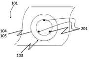
도 1은 본 발명에 따른 스마트폰 또는 태블릿 디스플레이의 개략도이다.
도 2는 본 발명에 따른 디스플레이 장치로 사운드를 재생하는 방법의 일 실시 예의 흐름도이다.
도 3은 본 발명에 따른 텔레비전의 다이어그램을 도시한다.
도 4는 본 발명에 따른 텔레비전의 다른 다이어그램을 도시한다.
도 5는 본 발명에 따른 텔레비전의 다른 다이어그램을 도시한다.
도 6은 본 발명에 따른 텔레비전의 다른 다이어그램을 도시한다.
도 7은 본 발명에 따른 텔레비전의 다른 다이어그램을 도시한다.
도 8은 본 발명에 따른 텔레비전의 다른 다이어그램을 도시한다.
도면들에서 달리 언급하지 않는 한 동일한 참조 부호는 동일한 요소를 나타낸다.For a more complete understanding of the present invention and its advantages, reference is now made to the following description in conjunction with the accompanying drawings. The invention is explained in greater detail using the exemplary embodiment specified in the schematic drawings of the drawings.
1 is a schematic diagram of a smartphone or tablet display according to the present invention.
2 is a flowchart of an embodiment of a method of reproducing sound with a display device according to the present invention.
3 shows a diagram of a television according to the invention.
4 shows another diagram of a television according to the invention.
5 shows another diagram of a television according to the invention.
6 shows another diagram of a television according to the invention.
7 shows another diagram of a television according to the invention.
8 shows another diagram of a television according to the invention.
The same reference numerals refer to the same elements unless otherwise indicated in the drawings.
도 1은 본 발명에 따른 디스플레이 장치(1)의 일 실시 예의 개략도를 도시한다.1 shows a schematic diagram of an embodiment of a
디스플레이 장치(1)는 스마트폰 또는 태블릿 디스플레이(1)이고, 이미징 평면(2)으로서 LCD 셀을 포함한다. LCD 셀(2)의 경우에, 디스플레이 장치(1) 또는 디스플레이 장치(1)에 의해 표시된 이미지를 조명하기 위해 별도의 조명이 필요한데, 그 이유는 LCD 셀(2)이 능동적으로 광을 방출할 수 없기 때문이다.The
따라서, 디스플레이 장치(1)는 가장자리 장착된 LED(7-1, 7-2)를 포함하는 백플레인(3)을 포함한다. LED(7-1, 7-2)만이 도 1에 도시되어 있지만, 임의의 적절한 개수의 LED가 디스플레이 장치(1)를 조명하는데 사용될 수 있다. 가장자리 장착된 LED(7-1, 7-2)의 경우, LED에 의해 광이 백플레인(3) 내로 방출되고, 가능한 한 균일하게 분포되어 이미징 평면(2)을 조명하고 디스플레이 장치(1)에 균질한 이미지를 제공한다. 이미징 평면(2) 및 백플레인(3)은 원칙적으로 디스플레이 장치(1)에 의해 이미지를 표시하기에 충분하다.The
본 발명은 디스플레이 장치(1)로 이미지를 표시하는 것 이외에도 전용 확성기를 요구하지 않으면서 디스플레이 장치(1)에 의해 가청음을 재생하는 수단도 제공한다. 따라서, 도 1에서 사운드 액추에이터(4)가 백플레인(3) 뒤에 배치된다. 사운드 액추에이터(4)는 구동 신호(5)에 기초하여 진동을 발생시키며, 상기 구동 신호(5)는 예를 들어 (도시 생략된) 오디오 증폭기(502)에 의해 생성될 수 있다(도 7 참조). 실제 가청 음파를 생성하기 위해, 사운드 액추에이터(4)는 결합 요소(6)를 통해 이미징 평면(2)에 기계적으로 접속되며, 상기 결합 요소(6)는 백플레인(3)을 가로지르고 상기 진동을 사운드 액추에이터(4)로부터 이미징 평면(2)으로 전달한다.In addition to displaying an image with the
따라서, 사운드 액추에이터(4) 또는 사운드 액추에이터(4)의 능동 요소가 진동하게 되면, 이 진동은 디스플레이 장치(1)의 전면으로 전달된다. 즉, 이미징 평면(2)이 그에 따라 진동하게 된다. 이미징 평면(2)이 진동하면, 그것은 음파를 방사하고 음파는 디스플레이 장치(1)의 전방에서 공기를 통해 진행하며, 예를 들어 디스플레이 장치(1) 부근의 사용자에 의해 가청음으로서 지각될 수 있다.Thus, when the sound actuator 4 or the active element of the sound actuator 4 is vibrated, the vibration is transmitted to the front of the
이미징 평면(2), 백플레인(3) 즉 LED(7-1, 7-2) 및 사운드 액추에이터(4)를 제어하는 제어 유닛과, 이들 요소들을 구동하기 위해 필요한 추가의 전기 회로는 이해를 용이하게 하기 위해 도시하지 않았다. 그러나 임의의 수의 그러한 제어 유닛 및 다른 회로가 필요에 따라 디스플레이 장치(1)에 통합될 수 있다는 것을 이해해야 한다.The control unit that controls the
도 2는 디스플레이 장치(1, 101)로 사운드를 재생하기 위한 본 발명에 따른 방법의 실시 예의 흐름도를 도시한다.2 shows a flowchart of an embodiment of a method according to the invention for reproducing sound with the
제1단계(S1)에서, 디스플레이 장치(1, 101) 내의 다수의 사운드 액추에이터(4, 104, 105)가 구동 신호(5)에 기초하여 진동을 생성한다. 제2단계(S2)에서, 이들 진동은 사운드 액추에이터(4, 104, 105) 각각에 대한 하나 이상의 기계적 결합 요소(6)에 의해 디스플레이 장치(1)의 백플레인(3)을 통해 디스플레이 장치의 이미징 평면(2, 103)에 전달된다.In a first step S1, a plurality of
진동을 기계적으로 전달하는 상기 단계(S2)는 지지봉(306-1 내지 306-3)에 의해 진동을 전달하는 과정을 포함하며, 상기 지지봉(306-1 내지 306-3)은 한쪽 끝이 사운드 액추에이터(4, 104, 105)에 결합하고, 다른 쪽 끝이 이미징 평면(2, 103)에 결합한다. 지지봉(306-1 내지 306-3)이 자유롭게 움직일 수 있도록, 내측 윤곽을 갖는 구멍(8-1 내지 8-3)이 백플레인(3)에 제공될 수 있으며, 상기 내측 윤곽은 지지봉(306-1 내지 306-3)의 외측 윤곽으로부터 미리 결정된 거리만큼 이격되어 있다. 이것은 지지봉(306-1 내지 306-3)이 움직이는 중에 백플레인(3)에 접촉하지 않는다는 것을 의미한다.The step (S2) of mechanically transmitting vibrations includes a process of transmitting vibrations by supporting rods 306-1 to 306-3, wherein the supporting rods 306-1 to 306-3 have one end at a sound actuator. (4, 104, 105) and the other end to the imaging plane (2, 103). In order for the support rods 306-1 to 306-3 to move freely, holes 8-1 to 8-3 with inner contours can be provided in the
디스플레이 장치(1)에 의해 표시되는 이미지를 조명하기 위해, 광은, 예를 들어 도광판(304)에 의해, 백플레인(3)에서 안내될 수 있다. 또한, 균일한 이미지를 제공하기 위해, 광은 도광판(304)으로부터 지지봉(306-1 내지 306-3)을 통해 이미징 평면(2)의 전면으로 적어도 부분적으로 안내될 수 있다. 광 투과를 개선하기 위해 광은 광 결합 요소(6)(예를 들어 도광판(304) 내의 프리즘 등)를 사용하여 지지봉(306-1 내지 306-3) 내로 커플링될 수 있다.In order to illuminate the image displayed by the
도 3은 본 발명에 따른 디스플레이 장치(101)의 일 실시 예의 다른 도면을 도시한다. 도 3의 디스플레이 장치는 LCD 텔레비전(101)으로서 구현된다.3 shows another view of an embodiment of a
텔레비전(101)은 LCD 셀(103)(즉, 이미징 평면)을 둘러싸는 전면 베젤(102)을 포함한다. 또한, 2개의 사운드 액추에이터(104, 105)가 도 3에서 점선 원으로 도시되어 있다. 점선 원은 사운드 액추에이터(104, 105)가 텔레비전(101)의 하우징 내부에 있지만 LCD 셀(103) 및 텔레비전(101)의 보이지 않는 백플레인 뒤에 위치한다는 것을 나타낸다.The
도 3의 구성은 LCD 셀(103)에 의해 스테레오 사운드를 재생할 수 있게 한다. 텔레비젼(101)의 전면에서 볼 때, 사운드 액추에이터(104)는 LCD 셀(103)의 상부 우측 코너 뒤에 위치되어 있다. 사운드 액추에이터(105)는 LCD 셀(103)의 하부 좌측 코너 뒤에 위치되어 있다. 사운드 액추에이터(104, 105)의 위치는 사운드 액추에이터(104, 105) 사이에 가능한 최대 거리를 제공한다. 따라서, 사운드 액추에이터(104, 105)의 진동은 서로 가능한 한 적게 간섭한다. 사운드 액추에이터(104, 105)와 전면 베젤(102) 사이에는 사운드 액추에이터(104, 105) 또는 LCD 셀(103)의 각 섹션이 자유롭게 진동할 수 있도록 하는 진동 마진이 제공되어야 한다. 따라서, 사운드 액추에이터(104, 105)는 LCD 셀(103)의 가장자리에는 배치되지 않고, 상기 진동 마진만큼 전면 베젤(102)로부터 이격된다.The configuration of FIG. 3 makes it possible to reproduce stereo sound by the
도 4는 디스플레이 장치(101), 특히 사운드 액추에이터(104, 105)를 갖는 LCD 셀(103)의 부분적인 다이어그램을 도시한다. 사운드 액추에이터(104, 105)를 갖는 LCD 셀(103)의 구성은 두 경우에 동일하기 때문에, 사운드 액추에이터(104, 105) 둘 다에 대해 하나의 다이어그램만이 도시되어 있다.4 shows a partial diagram of the
도 4에는 LCD 셀(103)의 3개의 픽셀(201)은 떨어져 표시되어 있는데, 그 이유는 이들 픽셀(201) 뒤에 지지봉(306-1 내지 306-3)(도 5 참조)이 LCD 셀(103)에 접촉하여 LCD 셀(103)을 각각의 사운드 액추에이터(104, 105)에 결합시키기 때문이다. 이것은, 광의 경로가 지지봉(306-1 내지 306-3)에 의해 방해되기 때문에 상기 3개의 픽셀(201)이 백플레인(3)을 통해 덜 조명될 수 있음을 의미한다.In FIG. 4, the three
실제 응용 예에서, 지지봉(306-1 내지 306-3)에는 광을 LCD 셀(103)의 전면으로 안내할 수 있는 재료가 제공될 수 있다. 예를 들면, 광은 도광판(304)(도 5 참조)으로부터 지지봉(306-1 내지 306-3)을 거친 다음 LCD 셀(103)로 커플링될 수 있다. 지지봉(306-1 내지 306-3)에 의해 LCD 셀(103)에 제공된 광이 LCD 셀(103)의 나머지 픽셀에서보다 적더라도, 이 차이는 사람의 눈에 의해 전혀 또는 거의 인지되지 않는다. LCD 셀(103)의 단일 픽셀들의 조명의 차이는 고해상도 디스플레이와 관련성이 더욱 낮아진다. 풀 HD 해상도의 50" 화면에는 인치 당 약 44 픽셀 또는 센티미터 당 17.3 픽셀이 있다. 4K UHD 해상도의 50" 화면에는 인치 당 약 88 픽셀 또는 센티미터 당 34.6 픽셀이 있다. 이것은 4K UHD의 모든 단일 픽셀은 폭이 0.28mm에 불과하다는 것을 의미한다.In practical applications, the support rods 306-1 through 306-3 can be provided with a material capable of guiding light to the front of the
도 5는 사운드 액추에이터(104, 105)를 갖는 디스플레이 장치(101)의 상세 측면도를 도시한다. 도 4와 같이, 두 부분이 동일하기 때문에 사운드 액추에이터(104, 105)의 하나만 도시되어 있다.5 shows a detailed side view of a
도 5에서, 백플레인(3)은 전면에서 후면으로 확산체 필름(diffuser film)(301), 프리즘 시트(302), 확산체 필름(303), 도광판(304), 반사체 시트(reflector sheet)(307) 및 금속 후면 커버(308)를 포함한다. 확산체 필름(301), 프리즘 시트(302), 확산체 필름(303), 도광판(304) 및 반사체 시트(307)는 함께 LCD 셀(103)을 위한 백라이트를 형성한다. 금속 후면 커버(308)는 이 필름 및 시트의 스택에 기계적 안정성을 제공한다.In FIG. 5, the
백플레인(3) 뒤에는 사운드 액추에이터(104, 105)가 제공되어 있으며, 이것은 백플레인(3)을 가로지르는 지지봉(306-1 내지 306-3)을 통해 LCD 셀(103)에 기계적으로 연결된다. 이를 위해서 구멍(8-1, 8-2, 8-3)(도 8 참조)이 백플레인(3)에 제공된다. 도광판(304) 및 지지봉(306-1 내지 306-3)은 모두 점 표시된 요소로서 도시되어 있다. 이는 도광판(304) 및 지지봉(306-1 내지 306-3)이 모두 동일하거나 유사한 재료를 포함하는 것을 설명하기 위한 것이다. 이 문맥에서 '유사한'은 재료의 광 안내 능력을 지칭한다. 이것은, 도광판(304)을 통과하는 광이 도광판(304)을 나가서 지지봉(306-1 내지 306-3) 내로 커플링하고, 지지봉(306-1 내지 306-3)이 상기 광을 LCD 셀(103)에 안내한다는 것을 의미한다.Behind the
도 6은 텔레비전(101)의 측 단면도를 나타낸다. 도 5에 이미 도시된 스택 순서는 전체의 텔레비전(101) 또는 텔레비전(101)의 전체 표면에 대해 제공된 것임을 도 6에서 알 수 있다. 도 3에 대응하여, 사운드 액추에이터(104)는 LCD 셀(103)의 상부 가장자리에 위치되고, 사운드 액추에이터(105)는 LCD 셀(103)의 하부 가장자리에 위치된다.6 shows a side sectional view of the
또한, LED(401)가 도광판(304)의 하부 가장자리에 도시되어 있다. 이 LED(401)는 단지 예시적이며 도광판(304)의 외주 상에 있을 수 있는 복수의 LED를 대표한다. 확산체 필름(301), 프리즘 시트(302), 확산체 필름(303), 도광판(304) 및 반사체 시트(307)로 이루어지는 상기 스택은, 가장자리 LED(401)의 광을 LCD 셀(103)의 표면에 대해 가능한 한 균일하게 분배할 것이다.
도 7은 확산체 필름(301), 프리즘 시트(302) 및 확산체 필름(303)을 포함하는 스택의 상세도를 도시한다. 추가의 층들이 3개의 점으로 암시된다.7 shows a detailed view of a stack comprising a
도시된 층들은 각각 지지봉(306-1 내지 306-3)이 백플레인(3)을 가로지르는 구멍(8-1, 8-2, 8-3)을 포함한다. 구멍(8-1, 8-2, 8-3)은 지지봉(306-1 내지 306-3)보다 더 커서 지지봉(306-1 내지 306-3)이 구멍(8-1, 8-2, 8-3) 내에서 자유롭게 움직일 수 있다.The illustrated layers each include holes 8-1, 8-2, and 8-3 through which the support rods 306-1 to 306-3 cross the
도 7에서, 구멍(8-1, 8-2, 8-3) 및 지지봉(306-1 내지 306-3)은 원형이다. 즉 둥근 단면을 갖는다. 정사각형, 타원형 또는 임의의 다른 단면 모양도 가능할 수 있음을 이해해야 한다.In Fig. 7, the holes 8-1, 8-2 and 8-3 and the supporting rods 306-1 to 306-3 are circular. That is, it has a round cross section. It should be understood that square, oval or any other cross sectional shape may be possible.
도 8은 본 발명에 따른 디스플레이 장치(101)의 일 실시 예의 블록도를 도시한다.8 is a block diagram of an embodiment of a
디스플레이 장치(101)는 오디오 증폭기(502)에 전자적으로 결합된 메인 보드(501)를 포함하며, 상기 오디오 증폭기(502)는 이어서 사운드 액추에이터(104, 105)에 전자적으로 결합되어 대응하는 구동 신호(5)로 상기 사운드 액추에이터(104, 105)를 구동한다.The
메인 보드(501)는 비디오 및 오디오 신호를 수신 또는 디코딩하고 상기 비디오 신호를 LCD 셀(103)에 전송하고 상기 오디오 신호를 오디오 증폭기(502)에 전송하는데 필요한 임의의 디지털 및/또는 프로그래머블 전자 회로를 포함할 수 있다.The
오디오 증폭기(502)는, 예를 들어 디지털 오디오 데이터 스트림을 수신하고, 상기 오디오 데이터 스트림을 각각의 오디오 데이터를 나타내는 아날로그 전압 또는 전류 신호로 변환하며 사운드 액추에이터(104, 105)에 제공될 때 사운드 액추에이터(104, 105)를 그에 따라 진동시킨다. 상기 오디오 데이터 스트림의 변환은 또한 메인 보드(501)에 의해 수행될 수도 있다는 것을 이해해야 하며, 메인 보드(501)는 오디오 증폭기(502)에 아날로그 오디오 신호를 제공할 수 있다.The
본 명세서에서 특정 실시 예가 도시되고 설명되었지만, 다양한 대체 및/또는 등가의 구현이 존재한다는 것은 통상의 기술자에게 자명하다. 예시적인 실시 예는 단지 예일 뿐이며, 어떤 방식으로든 범위, 적용 가능성 또는 구성을 제한하는 것을 의도하지 않는다는 것을 이해해야 한다. 오히려, 전술한 요약 및 상세한 설명은 하나 이상의 예시적인 실시 예를 구현하기 위한 편리한 로드맵을 통상의 기술자에게 제공할 것이며, 첨부된 청구항들 및 그들의 법적 등가물에 기재된 범위를 벗어나지 않으면서 본 발명의 실시 예에 기술된 요소들의 기능 및 배열에 다양한 변경이 가해질 수 있음을 이해해야 한다. 일반적으로, 본 출원은 본 명세서에서 논의된 특정 실시 예의 임의의 개조 또는 변형을 포괄하도록 의도된다.While specific embodiments have been shown and described herein, it will be apparent to those skilled in the art that various alternative and / or equivalent implementations exist. It is to be understood that the example embodiments are merely examples and are not intended to limit the scope, applicability, or configuration in any way. Rather, the foregoing summary and detailed description will provide those skilled in the art with a convenient roadmap for implementing one or more illustrative embodiments, and which do not depart from the scope of the appended claims and their legal equivalents. It should be understood that various changes may be made in the function and arrangement of elements described in the following. In general, this application is intended to cover any adaptations or variations of the specific embodiments discussed herein.
예를 들어, 스마트폰 디스플레이 및 LCD 텔레비전과 관련하여 설명되었지만, 본 발명은 디스플레이를 포함하고 사운드를 재생할 필요가 있는 임의의 장치와 함께 사용될 수 있다. 또한, LCD 기반 디스플레이뿐만 아니라, 예를 들어, 플라즈마-스크린, OLED 또는 AMOLED 디스플레이 등도 본 발명과 함께 사용될 수 있다.For example, while described in connection with smartphone displays and LCD televisions, the present invention may be used with any device that includes a display and needs to reproduce sound. In addition to LCD-based displays, for example, plasma-screen, OLED or AMOLED displays and the like can also be used with the present invention.
예를 들어 2개의 사운드 액추에이터를 갖는 텔레비전이 스테레오 오디오 시스템으로서 위에서 설명되었지만, 본 발명은 디스플레이 장치에 복수의 확성기를 제공함으로써 확성기들의 어레이를 제공하는데 사용될 수 있다. 이러한 확성기들의 어레이는 예를 들어 웨이브 필드 합성을 수행하기 위해 사용될 수 있다.For example, while a television having two sound actuators has been described above as a stereo audio system, the present invention can be used to provide an array of loudspeakers by providing a plurality of loudspeakers in a display device. Such an array of loudspeakers can be used, for example, to perform wave field synthesis.
전술한 본 발명은, 이미지를 제어 가능하게 표시하는 이미징 평면, 상기 이미징 평면 뒤에 위치된 백플레인, 구동 신호에 기초하여 진동을 생성하는 다수의 사운드 액추에이터, 그리고 상기 이미징 평면을 상기 백플레인을 통해 상기 사운드 액추에이터와 기계적으로 결합하는 모든 사운드 액추에이터를 위한 하나 이상의 기계적 결합 요소를 포함하는 디스플레이를 설명한다.The present invention described above includes an imaging plane that controllably displays an image, a backplane located behind the imaging plane, a plurality of sound actuators that generate vibration based on a drive signal, and the imaging plane through the backplane through the sound actuator. A display is described that includes one or more mechanical coupling elements for all sound actuators that mechanically couple with the.
1, 101디스플레이 장치
2, 103이미징 평면
3백플레인
4, 104, 105사운드 액추에이터
5구동 신호
6결합 요소
7-1, 7-2, 401LEDs
306-1 ~ 306-3지지봉
8-1 ~ 8-3구멍
304도광판
102전면 베젤
201픽셀
301, 303확산체 필름
302프리즘 시트
307반사체 시트
308금속 후면 커버
402중간 프레임
501메인보드
502오디오 증폭기1, 101 display device
2, 103 imaging planes
3 backplane
4, 104, 105 sound actuator
5 driving signal
6 coupling elements
7-1, 7-2, 401 LEDs
306-1 to 306-3 support rod
8-1 to 8-3 holes
304 light guide plate
102 front bezel
201 pixels
301, 303 diffuser film
302 prism sheet
307 reflector sheet
308 metal back cover
402 middle frame
501 mainboard
502 audio amplifier
Claims (10)
Translated fromKorean이미지를 제어 가능하게 표시하는 이미징 평면(2, 103);
상기 이미징 평면(2, 103)의 뒤에 위치된 백플레인(3);
구동 신호(5)에 기초하여 진동을 생성하는 다수의 사운드 액추에이터(4, 104, 105); 및
상기 이미징 평면(2, 103)과 상기 사운드 액추에이터(4, 104, 105)를 상기 백플레인(3)을 통해 기계적으로 결합하는, 상기 사운드 액추에이터(4, 104, 105) 각각에 대하여 하나 이상의 기계적 결합 요소(6);를 포함하고
상기 기계적 결합 요소(6)는 각각 다수의 지지봉들(306-1 ~ 306-3)을 포함하고, 상기 지지봉들은 한쪽 끝이 상기 사운드 액추에이터(4, 104, 105)에 결합되고 다른 쪽 끝이 이미징 평면(2, 103)에 결합되며,
상기 백플레인(3)은 내측 윤곽을 갖는 상기 지지봉들(306-1 ~ 306-3)을 위한 구멍들(8-1 ~ 8-3)을 포함하고, 상기 내측 윤곽은 상기 지지봉들(306-1 ~ 306-3)의 외측 윤곽으로부터 미리결정된 거리만큼 이격되고,
상기 백플레인(3)은 도광판(304)을 포함하고,
상기 지지봉들(306-1 ~ 306-3)은 광을 부분적으로 또는 전체적으로 안내하는 재료를 포함하는, 디스플레이 장치.In the display device (1, 101),
Imaging planes 2, 103 for controllably displaying an image;
A backplane (3) located behind the imaging plane (2, 103);
A plurality of sound actuators 4, 104, 105 for generating vibrations based on the drive signal 5; And
One or more mechanical coupling elements for each of the sound actuators 4, 104, 105, which mechanically couple the imaging planes 2, 103 and the sound actuators 4, 104, 105 through the backplane 3. (6); and
The mechanical coupling element 6 comprises a plurality of support rods 306-1 to 306-3, respectively, with one end coupled to the sound actuators 4, 104 and 105 and the other end being imaged. Coupled to planes 2, 103,
The backplane 3 comprises holes 8-1 to 8-3 for the supporting rods 306-1 to 306-3 having an inner contour, the inner contour of the supporting rods 306-1. 306-3), spaced apart from the outer contour by a predetermined distance,
The backplane 3 includes a light guide plate 304,
And the support rods (306-1 through 306-3) comprise a material that guides the light partially or fully.
상기 도광판(304) 내 상기 구멍들(8-1 ~ 8-3)의 가장자리들에 광 결합 요소를 포함하고,
상기 광 결합 요소는 상기 도광판(304)으로부터 상기 지지봉들(306-1 ~ 306-3) 내로 광을 커플링하는, 디스플레이 장치.The method of claim 1,
A light coupling element at edges of the holes 8-1 to 8-3 in the light guide plate 304,
And the light coupling element couples light from the light guide plate (304) into the support rods (306-1 through 306-3).
상기 지지봉들(306-1 ~ 306-3)의 단면은 상기 이미징 평면(2, 103)의 3개 이하의 픽셀인, 디스플레이 장치.The method according to claim 1 or 3,
Wherein the cross sections of the support rods (306-1 to 306-3) are no more than three pixels in the imaging plane (2, 103).
상기 디스플레이 장치(1, 101)의 정면도에서 상기 디스플레이 장치(1, 101)의 상기 이미징 평면(2, 103)의 뒤쪽 상기 디스플레이 장치(1, 101)의 대향하는 측의 상이한 높이에 배치되는 2개의 사운드 액추에이터(4, 104, 105)를 포함하는, 디스플레이 장치.The method according to claim 1 or 3,
In the front view of the display device 1, 101 two are arranged at different heights on opposite sides of the display device 1, 101 behind the imaging planes 2, 103 of the display device 1, 101. Display device comprising sound actuators (4, 104, 105).
상기 디스플레이 장치(1, 101) 내의 다수의 사운드 액추에이터(4, 1014, 105)에 의해 구동 신호(5)에 기초하여 진동을 생성하는 단계(S1); 및
상기 사운드 액추에이터(4, 104, 105) 각각에 대하여 하나 이상의 기계적 결합 요소(6)에 의해 상기 진동을 상기 디스플레이 장치(1, 101)의 백플레인(3)을 통해 상기 디스플레이 장치(1, 101)의 이미징 평면(2, 103)에 기계적으로 전달하는 단계(S2);를 포함하고,
상기 진동을 기계적으로 전달하는 단계는 지지봉들(306-1 ~ 306-3)에 의해 상기 진동을 전달하는 과정을 포함하고,
상기 지지봉들(306-1 ~ 306-3)은, 상기 백플레인(3) 내 구멍들(8-1 ~ 8-3)을 통해, 한쪽 끝이 상기 사운드 액추에이터(4, 104, 105)에 결합되고 다른 쪽 끝이 상기 이미징 평면(2, 103)에 결합되며,
상기 구멍들(8-1 ~ 8-3)은 상기 지지봉들(306-1 ~ 306-3)의 외측 윤곽으로부터 미리결정된 거리만큼 이격된 내측 윤곽을 가지며,
상기 하나 이상의 기계적 결합 요소(6)는 각각 상기 지지봉들(306-1 ~ 306-3)을 포함하고,
상기 백플레인(3)은 도광판(304)을 포함하고,
상기 도광판(304)에 의해 상기 백플레인(3)에서 광을 안내하는 단계 및 상기 도광판(304)으로부터 상기 지지봉들(306-1 ~ 306-3)을 통해 부분적으로 또는 전체적으로 상기 광을 안내하는 단계를 추가로 포함하는,
사운드 재생 방법.In the method of reproducing the sound by the display device (1, 101),
Generating vibrations (S1) based on a drive signal (5) by a plurality of sound actuators (4, 1014, 105) in the display device (1, 101); And
For each of the sound actuators 4, 104, 105 one or more mechanical coupling elements 6 transmit the vibration via the backplane 3 of the display device 1, 101 of the display device 1, 101. Mechanically transferring it to the imaging planes (2, 103) (S2);
The mechanically transmitting the vibration includes transmitting the vibration by the supporting rods 306-1 to 306-3,
The supporting rods 306-1 to 306-3 are coupled to the sound actuators 4, 104 and 105 at one end through the holes 8-1 to 8-3 in the backplane 3. The other end is coupled to the imaging plane (2, 103),
The holes 8-1 to 8-3 have an inner contour spaced a predetermined distance from the outer contour of the support rods 306-1 to 306-3,
Said at least one mechanical coupling element 6 each comprising said support rods 306-1 to 306-3,
The backplane 3 includes a light guide plate 304,
Guiding light in the backplane 3 by the light guide plate 304 and guiding the light partially or entirely from the light guide plate 304 through the support rods 306-1 to 306-3. Additionally included,
How to play sound.
상기 도광판(304) 내의 광 결합 요소에 의해 광을 상기 지지봉들(306-1 ~ 306-3) 내로 커플링하는 단계를 추가로 포함하는, 사운드 재생 방법.The method of claim 6,
Coupling the light into the support rods (306-1 through 306-3) by means of a light coupling element in the light guide plate (304).
상기 진동을 기계적으로 전달하는 단계는 지지봉들(306-1 ~ 306-3)에 의해 상기 진동을 전달하는 과정을 포함하고,
상기 지지봉들(306-1 ~ 306-3)의 단면은 상기 이미징 평면(2, 103)의 3개 이하의 픽셀인, 사운드 재생 방법.The method according to claim 6 or 8,
The mechanically transmitting the vibration includes transmitting the vibration by the supporting rods 306-1 to 306-3,
Wherein the cross sections of the support rods (306-1 to 306-3) are no more than three pixels in the imaging plane (2, 103).
상기 디스플레이 장치(1, 101)의 정면도에서 상기 디스플레이 장치(1, 101)의 상기 이미징 평면(2, 103)의 뒤쪽 상기 디스플레이 장치(1, 101)의 대향하는 측의 상이한 높이에 배치되는 2개의 사운드 액추에이터(4, 104, 105)에 의해, 또는 웨이브 필드(wave field) 합성을 집합적으로 수행하는 복수의 사운드 액추에이터(4, 104, 105)에 의해 상기 진동을 기계적으로 전달하는 단계를 추가로 포함하는, 사운드 재생 방법.The method according to claim 6 or 8,
In the front view of the display device 1, 101 two are arranged at different heights on opposite sides of the display device 1, 101 behind the imaging planes 2, 103 of the display device 1, 101. Mechanically transmitting the vibrations by sound actuators 4, 104, 105 or by a plurality of sound actuators 4, 104, 105 which collectively perform wave field synthesis. Including, sound playback method.
Applications Claiming Priority (3)
| Application Number | Priority Date | Filing Date | Title |
|---|---|---|---|
| EP15184991.6 | 2015-09-14 | ||
| EP15184991.6AEP3142385B1 (en) | 2015-09-14 | 2015-09-14 | Sound reproducing display |
| PCT/EP2016/071690WO2017046161A1 (en) | 2015-09-14 | 2016-09-14 | Sound reproducing display |
Publications (2)
| Publication Number | Publication Date |
|---|---|
| KR20180050691A KR20180050691A (en) | 2018-05-15 |
| KR102082585B1true KR102082585B1 (en) | 2020-02-27 |
Family
ID=54151092
Family Applications (1)
| Application Number | Title | Priority Date | Filing Date |
|---|---|---|---|
| KR1020187009437AExpired - Fee RelatedKR102082585B1 (en) | 2015-09-14 | 2016-09-14 | Sound playback display device and method |
Country Status (7)
| Country | Link |
|---|---|
| US (1) | US10511912B2 (en) |
| EP (1) | EP3142385B1 (en) |
| JP (1) | JP7049990B2 (en) |
| KR (1) | KR102082585B1 (en) |
| CN (2) | CN108028990B (en) |
| TR (1) | TR201702620A2 (en) |
| WO (1) | WO2017046161A1 (en) |
Families Citing this family (10)
| Publication number | Priority date | Publication date | Assignee | Title |
|---|---|---|---|---|
| EP3142385B1 (en)* | 2015-09-14 | 2020-01-08 | Vestel Elektronik Sanayi ve Ticaret A.S. | Sound reproducing display |
| US10142739B2 (en)* | 2016-03-28 | 2018-11-27 | Lg Display Co., Ltd. | Panel vibration type display device for generating sound |
| KR102266209B1 (en)* | 2017-04-29 | 2021-06-16 | 엘지디스플레이 주식회사 | Display apparatus |
| CN111819865B (en)* | 2018-03-06 | 2022-06-14 | Agc株式会社 | Loudspeaker device |
| CN109102762B (en)* | 2018-09-25 | 2024-03-29 | 深圳市奥拓电子股份有限公司 | LED composite lamp, LED display module and LED display screen |
| US11923617B2 (en)* | 2018-10-31 | 2024-03-05 | Nokia Technologies Oy | Apparatus for reflecting electromagnetic waves and method of operating such apparatus |
| CN109495832B (en)* | 2018-11-27 | 2020-08-25 | 歌尔股份有限公司 | Surface sound generating device and electronic equipment |
| DE102020104879A1 (en)* | 2019-02-28 | 2020-09-03 | Lg Display Co., Ltd. | Display device |
| CN114902692B (en)* | 2020-01-24 | 2025-08-15 | 索尼集团公司 | Display device and speaker device |
| JP2022174513A (en)* | 2021-05-11 | 2022-11-24 | Necパーソナルコンピュータ株式会社 | Information processing apparatus and control method |
Citations (1)
| Publication number | Priority date | Publication date | Assignee | Title |
|---|---|---|---|---|
| US20140241558A1 (en)* | 2013-02-27 | 2014-08-28 | Nokia Corporation | Multiple Audio Display Apparatus And Method |
Family Cites Families (16)
| Publication number | Priority date | Publication date | Assignee | Title |
|---|---|---|---|---|
| US5828768A (en)* | 1994-05-11 | 1998-10-27 | Noise Cancellation Technologies, Inc. | Multimedia personal computer with active noise reduction and piezo speakers |
| SK25598A3 (en)* | 1995-09-02 | 1998-10-07 | New Transducers Ltd | Inertial vibration transducers |
| CN1194767A (en) | 1995-09-02 | 1998-09-30 | 新型转换器有限公司 | Inertial vibrative transducer |
| JP3591578B2 (en)* | 1999-11-09 | 2004-11-24 | ヤマハ株式会社 | Acoustic radiator |
| GB2360901A (en) | 2000-03-29 | 2001-10-03 | Nokia Mobile Phones Ltd | A loudspeaker which uses an electronic display as a diaphragm |
| JP3966318B2 (en)* | 2004-09-09 | 2007-08-29 | セイコーエプソン株式会社 | Electro-optical device and electronic apparatus |
| JP2007043412A (en)* | 2005-08-02 | 2007-02-15 | Teijin Fibers Ltd | Screen with speaker function |
| JP2007104602A (en)* | 2005-10-07 | 2007-04-19 | Sony Corp | Image display apparatus and sound output method |
| JP5056038B2 (en)* | 2007-02-06 | 2012-10-24 | カシオ計算機株式会社 | Image display module |
| TW201312922A (en)* | 2011-09-13 | 2013-03-16 | Chief Land Electronic Co Ltd | Transducer module |
| CN102917299B (en)* | 2012-01-12 | 2015-08-12 | 瑞声声学科技(深圳)有限公司 | Screen sounder |
| CN103576356A (en) | 2012-07-23 | 2014-02-12 | 天津富纳源创科技有限公司 | Production method for liquid crystal module having touch function |
| TW201513678A (en)* | 2013-09-25 | 2015-04-01 | Hon Hai Prec Ind Co Ltd | Speaker and display |
| CN103778909B (en)* | 2014-01-10 | 2017-03-01 | 瑞声科技(南京)有限公司 | Screen sonification system and its control method |
| CN104216576B (en)* | 2014-08-27 | 2018-05-11 | 合肥鑫晟光电科技有限公司 | A kind of surface acoustic wave touch screen and touch display unit |
| EP3142385B1 (en)* | 2015-09-14 | 2020-01-08 | Vestel Elektronik Sanayi ve Ticaret A.S. | Sound reproducing display |
- 2015
- 2015-09-14EPEP15184991.6Apatent/EP3142385B1/enactiveActive
- 2016
- 2016-09-14JPJP2018513443Apatent/JP7049990B2/enactiveActive
- 2016-09-14USUS15/754,183patent/US10511912B2/enactiveActive
- 2016-09-14WOPCT/EP2016/071690patent/WO2017046161A1/ennot_activeCeased
- 2016-09-14CNCN201680052763.8Apatent/CN108028990B/enactiveActive
- 2016-09-14KRKR1020187009437Apatent/KR102082585B1/ennot_activeExpired - Fee Related
- 2016-09-14CNCN202010838189.7Apatent/CN111970614B/enactiveActive
- 2017
- 2017-02-22TRTR2017/02620Apatent/TR201702620A2/enunknown
Patent Citations (1)
| Publication number | Priority date | Publication date | Assignee | Title |
|---|---|---|---|---|
| US20140241558A1 (en)* | 2013-02-27 | 2014-08-28 | Nokia Corporation | Multiple Audio Display Apparatus And Method |
Also Published As
| Publication number | Publication date |
|---|---|
| EP3142385B1 (en) | 2020-01-08 |
| US10511912B2 (en) | 2019-12-17 |
| TR201702620A2 (en) | 2018-03-21 |
| CN111970614A (en) | 2020-11-20 |
| US20180249251A1 (en) | 2018-08-30 |
| EP3142385A1 (en) | 2017-03-15 |
| CN111970614B (en) | 2022-01-04 |
| KR20180050691A (en) | 2018-05-15 |
| CN108028990A (en) | 2018-05-11 |
| JP7049990B2 (en) | 2022-04-07 |
| JP2018534810A (en) | 2018-11-22 |
| CN108028990B (en) | 2020-09-15 |
| WO2017046161A1 (en) | 2017-03-23 |
Similar Documents
| Publication | Publication Date | Title |
|---|---|---|
| KR102082585B1 (en) | Sound playback display device and method | |
| CN111383563B (en) | Display device | |
| KR101919454B1 (en) | Display apparatus and computing apparatus | |
| KR102453657B1 (en) | Display apparatus | |
| CN215453262U (en) | Electronic device | |
| CN111192540A (en) | Display device | |
| KR102068986B1 (en) | Display apparatus and computing apparatus | |
| KR102458174B1 (en) | Electronic apparatus | |
| KR20200083118A (en) | Display apparatus | |
| KR102276727B1 (en) | Display apparatus and computing apparatus | |
| JP2009232297A (en) | Display device | |
| KR102660865B1 (en) | Display apparatus and computing apparatus |
Legal Events
| Date | Code | Title | Description |
|---|---|---|---|
| PA0105 | International application | St.27 status event code:A-0-1-A10-A15-nap-PA0105 | |
| A201 | Request for examination | ||
| PA0201 | Request for examination | St.27 status event code:A-1-2-D10-D11-exm-PA0201 | |
| P11-X000 | Amendment of application requested | St.27 status event code:A-2-2-P10-P11-nap-X000 | |
| P13-X000 | Application amended | St.27 status event code:A-2-2-P10-P13-nap-X000 | |
| PG1501 | Laying open of application | St.27 status event code:A-1-1-Q10-Q12-nap-PG1501 | |
| R17-X000 | Change to representative recorded | St.27 status event code:A-3-3-R10-R17-oth-X000 | |
| R17-X000 | Change to representative recorded | St.27 status event code:A-3-3-R10-R17-oth-X000 | |
| R17-X000 | Change to representative recorded | St.27 status event code:A-3-3-R10-R17-oth-X000 | |
| E902 | Notification of reason for refusal | ||
| PE0902 | Notice of grounds for rejection | St.27 status event code:A-1-2-D10-D21-exm-PE0902 | |
| P11-X000 | Amendment of application requested | St.27 status event code:A-2-2-P10-P11-nap-X000 | |
| P13-X000 | Application amended | St.27 status event code:A-2-2-P10-P13-nap-X000 | |
| E902 | Notification of reason for refusal | ||
| PE0902 | Notice of grounds for rejection | St.27 status event code:A-1-2-D10-D21-exm-PE0902 | |
| T11-X000 | Administrative time limit extension requested | St.27 status event code:U-3-3-T10-T11-oth-X000 | |
| E13-X000 | Pre-grant limitation requested | St.27 status event code:A-2-3-E10-E13-lim-X000 | |
| P11-X000 | Amendment of application requested | St.27 status event code:A-2-2-P10-P11-nap-X000 | |
| P13-X000 | Application amended | St.27 status event code:A-2-2-P10-P13-nap-X000 | |
| E701 | Decision to grant or registration of patent right | ||
| PE0701 | Decision of registration | St.27 status event code:A-1-2-D10-D22-exm-PE0701 | |
| PR0701 | Registration of establishment | St.27 status event code:A-2-4-F10-F11-exm-PR0701 | |
| PR1002 | Payment of registration fee | St.27 status event code:A-2-2-U10-U12-oth-PR1002 Fee payment year number:1 | |
| PG1601 | Publication of registration | St.27 status event code:A-4-4-Q10-Q13-nap-PG1601 | |
| PR1001 | Payment of annual fee | St.27 status event code:A-4-4-U10-U11-oth-PR1001 Fee payment year number:4 | |
| PC1903 | Unpaid annual fee | St.27 status event code:A-4-4-U10-U13-oth-PC1903 Not in force date:20240222 Payment event data comment text:Termination Category : DEFAULT_OF_REGISTRATION_FEE | |
| PC1903 | Unpaid annual fee | St.27 status event code:N-4-6-H10-H13-oth-PC1903 Ip right cessation event data comment text:Termination Category : DEFAULT_OF_REGISTRATION_FEE Not in force date:20240222 |