KR102078058B1 - Electronic power steering system detecting temperature error due to electromagnetic interference and controlling method thereof - Google Patents
Electronic power steering system detecting temperature error due to electromagnetic interference and controlling method thereofDownload PDFInfo
- Publication number
- KR102078058B1 KR102078058B1KR1020180157130AKR20180157130AKR102078058B1KR 102078058 B1KR102078058 B1KR 102078058B1KR 1020180157130 AKR1020180157130 AKR 1020180157130AKR 20180157130 AKR20180157130 AKR 20180157130AKR 102078058 B1KR102078058 B1KR 102078058B1
- Authority
- KR
- South Korea
- Prior art keywords
- temperature
- condition
- normal operation
- power steering
- steering system
- Prior art date
- Legal status (The legal status is an assumption and is not a legal conclusion. Google has not performed a legal analysis and makes no representation as to the accuracy of the status listed.)
- Active
Links
Images


Classifications
- B—PERFORMING OPERATIONS; TRANSPORTING
- B62—LAND VEHICLES FOR TRAVELLING OTHERWISE THAN ON RAILS
- B62D—MOTOR VEHICLES; TRAILERS
- B62D5/00—Power-assisted or power-driven steering
- B62D5/04—Power-assisted or power-driven steering electrical, e.g. using an electric servo-motor connected to, or forming part of, the steering gear
- B62D5/0457—Power-assisted or power-driven steering electrical, e.g. using an electric servo-motor connected to, or forming part of, the steering gear characterised by control features of the drive means as such
- B62D5/0481—Power-assisted or power-driven steering electrical, e.g. using an electric servo-motor connected to, or forming part of, the steering gear characterised by control features of the drive means as such monitoring the steering system, e.g. failures
- B62D5/0493—Power-assisted or power-driven steering electrical, e.g. using an electric servo-motor connected to, or forming part of, the steering gear characterised by control features of the drive means as such monitoring the steering system, e.g. failures detecting processor errors, e.g. plausibility of steering direction
- B—PERFORMING OPERATIONS; TRANSPORTING
- B62—LAND VEHICLES FOR TRAVELLING OTHERWISE THAN ON RAILS
- B62D—MOTOR VEHICLES; TRAILERS
- B62D5/00—Power-assisted or power-driven steering
- B62D5/04—Power-assisted or power-driven steering electrical, e.g. using an electric servo-motor connected to, or forming part of, the steering gear
- B62D5/0457—Power-assisted or power-driven steering electrical, e.g. using an electric servo-motor connected to, or forming part of, the steering gear characterised by control features of the drive means as such
- B62D5/046—Controlling the motor
- B62D5/0463—Controlling the motor calculating assisting torque from the motor based on driver input
- B—PERFORMING OPERATIONS; TRANSPORTING
- B62—LAND VEHICLES FOR TRAVELLING OTHERWISE THAN ON RAILS
- B62D—MOTOR VEHICLES; TRAILERS
- B62D5/00—Power-assisted or power-driven steering
- B62D5/04—Power-assisted or power-driven steering electrical, e.g. using an electric servo-motor connected to, or forming part of, the steering gear
- B62D5/0457—Power-assisted or power-driven steering electrical, e.g. using an electric servo-motor connected to, or forming part of, the steering gear characterised by control features of the drive means as such
- B62D5/0481—Power-assisted or power-driven steering electrical, e.g. using an electric servo-motor connected to, or forming part of, the steering gear characterised by control features of the drive means as such monitoring the steering system, e.g. failures
- B62D5/0484—Power-assisted or power-driven steering electrical, e.g. using an electric servo-motor connected to, or forming part of, the steering gear characterised by control features of the drive means as such monitoring the steering system, e.g. failures for reaction to failures, e.g. limp home
Landscapes
- Engineering & Computer Science (AREA)
- Chemical & Material Sciences (AREA)
- Combustion & Propulsion (AREA)
- Transportation (AREA)
- Mechanical Engineering (AREA)
- Steering Control In Accordance With Driving Conditions (AREA)
- Power Steering Mechanism (AREA)
Abstract
Translated fromKoreanDescription
Translated fromKorean본 발명은 전동식 파워 스티어링 시스템(Electronic power steering system; 이하, “EPS 시스템”이라 지칭) 및 그 제어 방법에 관한 것으로서, 더욱 상세하게는 전자파 간섭에 의한 온도 오류를 검출하여 이에 대응 제어하는 EPS 시스템의 ECU 및 그 제어 방법에 관한 것이다.BACKGROUND OF THE INVENTION 1. Field of the Invention The present invention relates to an electronic power steering system (hereinafter referred to as an “EPS system”) and a control method thereof, and more particularly, to an apparatus for detecting and controlling a temperature error caused by electromagnetic interference. An ECU and a control method thereof.
EPS 시스템은 전자 제어 장치(Electronic control unit; 이하, “ECU”라 지칭)를 이용하여 차량의 속도에 따라 모터의 구동에 의해 어시스트량을 조절함으로써 핸들의 파워스티어링 특성을 조절하는 시스템이다. 이때, ECU는 차량의 각종 입력 센서에서 검출되는 전기적 신호를 입력 받아 출력 측의 각종 액츄에이터를 구동하기 위한 디지털 제어신호를 출력하는 제어 장치이다.The EPS system is a system that adjusts the power steering characteristics of the steering wheel by adjusting the assist amount by driving the motor according to the speed of the vehicle using an electronic control unit (hereinafter referred to as “ECU”). At this time, the ECU is a control device that receives the electrical signals detected by the various input sensors of the vehicle and outputs a digital control signal for driving the various actuators on the output side.
이러한 EPS 시스템은 운전자가 핸들을 조작할 경우 토크 센서가 운전자의 핸들 토크 입력을 감지하여 ECU로 전달하고, 이 핸들 토크 입력을 전달받은 전자 제어 장치의 명령에 의해 모터가 구동하여 조향을 어시스트함으로써 핸들의 파워스트어링 특성을 조절한다. 즉, EPS 시스템에서, ECU는 차량 속도가 낮을 경우에 핸들의 파워스티어링이 가벼워지도록 제어할 수 있으며, 차량 속도가 빠를 경우에 핸들의 파워스티어링이 무거워지도록 제어할 수 있다.In this EPS system, when the driver manipulates the steering wheel, the torque sensor senses the driver's steering torque input and transmits it to the ECU, and the steering wheel input assists steering by driving the motor by the command of the electronic control device. Adjust the powerstring characteristics of the That is, in the EPS system, the ECU may control the steering wheel to be lighter when the vehicle speed is low, and when the vehicle speed is high, the steering wheel may be heavy.
한편, 종래의 EPS 시스템에서, ECU는 자신의 온도를 검출하는 온도 센서를 구비한다. 이때, 온도 센서에서 검출된의 온도가 일정 이상으로 상승하는 경우, ECU의 온도를 줄이기 위해, ECU는 모터 구동신호가 평상 시 보다 줄어들도록 제어한다. 이 경우, 주행 중인 운전자에게 전달되는 파워 스티어링 조향감이 달라지게 되므로, 달라진 핸들 조작에 의한 사고가 발생될 수 있다.On the other hand, in the conventional EPS system, the ECU is provided with a temperature sensor for detecting its temperature. At this time, when the temperature detected by the temperature sensor rises above a certain level, in order to reduce the temperature of the ECU, the ECU controls the motor drive signal to be reduced than usual. In this case, since the power steering steering feeling transmitted to the driving driver is changed, an accident due to a changed steering wheel operation may occur.
하지만, 온도 센서는 외부에서 유입되는 레이더파 등의 전자파 간섭이 발생하는 경우에 오작동을 할 수 있다. 이 경우, 실제로는 정상 온도임에도 오작동된 온도 센서에서 검출된 온도가 일정 이상이 됨에 따라, ECU가 모터 구동신호를 줄이도록 제어하는 문제점이 발생할 수 있다.However, the temperature sensor may malfunction when electromagnetic interference such as radar waves introduced from the outside occurs. In this case, as the temperature detected by the malfunctioning temperature sensor becomes a certain level even though the temperature is actually normal, a problem of controlling the ECU to reduce the motor driving signal may occur.
상기한 바와 같은 종래 기술의 문제점을 해결하기 위하여, 본 발명은 전자파 간섭에 의한 온도 오류를 검출하여 이에 대응 제어하는 EPS 시스템 및 그 제어 방법을 제공하는 데 그 목적이 있다.SUMMARY OF THE INVENTION In order to solve the problems of the prior art as described above, an object of the present invention is to provide an EPS system and a control method thereof for detecting and controlling a temperature error caused by electromagnetic interference.
다만, 본 발명이 해결하고자 하는 과제는 이상에서 언급한 과제에 제한되지 않으며, 언급되지 않은 또 다른 과제들은 아래의 기재로부터 당업자에게 명확하게 이해될 수 있을 것이다.However, the problem to be solved by the present invention is not limited to the above-mentioned problem, another problem that is not mentioned will be clearly understood by those skilled in the art from the following description.
상기와 같은 과제를 해결하기 위한 본 발명의 일 실시예에 따른 EPS 시스템은 전자파 간섭에 의한 온도 오류에 대응하는 이중화(Redundancy) 구조의 전자 제어 장치를 포함하는 EPS 시스템으로서, 마스터로 작동 중인 전자 제어 장치의 제1 온도와 슬레이브로 작동 중인 전자 제어 장치의 제2 온도를 이용하여, 정상 동작이나 비상 동작을 수행한다.An EPS system according to an embodiment of the present invention for solving the above problems is an EPS system including an electronic control device having a redundancy structure corresponding to a temperature error caused by electromagnetic interference, the electronic control operating as a master Using the first temperature of the device and the second temperature of the electronic control device operating as a slave, a normal operation or an emergency operation is performed.
상기 비상 동작은 상기 제1 온도가 제1 기준 이상인 제1 조건에서 동작하되, 정상 동작의 경우 보다 줄어든 모터 출력 토크를 위한 모터 구동신호를 출력하도록 제어하는 동작일 수 있다.The emergency operation may be an operation of operating a first condition in which the first temperature is equal to or greater than a first reference, and outputting a motor driving signal for a reduced motor output torque in a normal operation.
다만, 본 발명의 일 실시예에 따른 EPS 시스템은 상기 제1 조건이더라도, 상기 제2 온도가 상기 제1 온도 보다 높은 제2 조건에서 정상 동작을 수행할 수 있다.However, the EPS system according to an embodiment of the present invention may perform a normal operation under a second condition in which the second temperature is higher than the first temperature even in the first condition.
또한, 본 발명의 일 실시예에 따른 EPS 시스템은 상기 제1 조건이고 상기 제1 온도가 상기 제2 온도 보다 높더라도, 상기 제1 온도가 제2 기준 보다 큰 차이로 상기 제2 온도 보다 높은 제3 조건에서 정상 동작을 수행할 수 있다.In addition, the EPS system according to an embodiment of the present invention is the first condition and even if the first temperature is higher than the second temperature, the first temperature is higher than the second temperature by a difference greater than the second reference Normal operation can be performed under 3 conditions.
한편, 상기 전자파는 레이더 펄스파일 수 있다.On the other hand, the electromagnetic wave may be a radar pulse file.
이때, 본 발명의 일 실시예에 따른 EPS 시스템은 상기 제1 조건이더라도, 상기 제2 조건이면서 상기 제1 온도 및 상기 제2 온도가 일정 이하의 간격으로 반복되는 다양한 펄스 형태를 가지는 제4 조건에서 정상 동작을 수행할 수 있다.In this case, the EPS system according to an embodiment of the present invention may be the second condition, but in the fourth condition having the various pulse shapes in which the first temperature and the second temperature are repeated at a predetermined interval or less, even though the second condition is the second condition. Normal operation can be performed.
또한, 상기 제4 조건은 펄스 형태 내에서 상기 제2 조건을 만족할 수 있다.In addition, the fourth condition may satisfy the second condition within a pulse shape.
본 발명의 일 실시예에 따른 EPS 시스템의 제어 방법은 전자파 간섭에 의한 온도 오류에 대응하는 이중화(Redundancy) 구조의 전자 제어 장치(Electronic Control Unit; ECU)를 포함하는 전동식 파워 스티어링 시스템의 제어 방법으로서, 마스터로 작동 중인 전자 제어 장치의 제1 온도와 슬레이브로 작동 중인 전자 제어 장치의 제2 온도를 이용하여, 정상 동작이나 비상 동작을 수행하는 제어 단계를 포함한다.A control method of an EPS system according to an embodiment of the present invention is a control method of an electric power steering system including an electronic control unit (ECD) having a redundancy structure corresponding to a temperature error caused by electromagnetic interference. And a control step of performing a normal operation or an emergency operation by using the first temperature of the electronic control device operating as the master and the second temperature of the electronic control device operating as the slave.
상기 비상 동작은 상기 제1 온도가 제1 기준 이상인 제1 조건에서 동작하되, 정상 동작의 경우 보다 줄어든 모터 출력 토크를 위한 모터 구동신호를 출력하도록 제어하는 동작일 수 있다.The emergency operation may be an operation of operating a first condition in which the first temperature is equal to or greater than a first reference, and outputting a motor driving signal for a reduced motor output torque in a normal operation.
다만, 상기 제어 단계는 상기 제1 조건이더라도, 제1 온도가 일정 이상이고 제1 온도가 제2 온도 보다 높은 제2 조건에서 정상 동작을 수행하는 단계를 포함할 수 있다.However, the control step may include performing a normal operation under a second condition in which the first temperature is higher than a certain level and the first temperature is higher than the second temperature even in the first condition.
또한, 상기 제어 단계는, 상기 제1 조건이고 상기 제1 온도가 상기 제2 온도 보다 높더라도, 상기 제1 온도가 제2 기준 보다 큰 차이로 상기 제2 온도 보다 높은 제3 조건에서 정상 동작을 수행하는 단계를 포함할 수 있다.In addition, the control may include the normal operation under the third condition higher than the second temperature by a difference greater than the second reference, even if the first condition is higher than the second temperature. It may include performing a step.
한편, 상기 전자파는 레이더 펄스파일 수 있다.On the other hand, the electromagnetic wave may be a radar pulse file.
이때, 상기 제어 단계는, 상기 제1 조건이더라도, 상기 제2 조건이면서 상기 제1 온도 및 상기 제2 온도가 일정 이하의 간격으로 반복되는 다양한 펄스 형태를 가지는 제4 조건에서 정상 동작을 수행하는 단계를 포함할 수 있다.In this case, the controlling step may include performing a normal operation in a fourth condition having the various pulse shapes in which the first temperature and the second temperature are repeated at a predetermined interval or less, even though the first condition is the second condition. It may include.
또한, 상기 제4 조건은 펄스 형태 내에서 상기 제2 조건을 만족할 수 있다.In addition, the fourth condition may satisfy the second condition within a pulse shape.
상기와 같이 구성되는 본 발명의 일 실시예에 따른 EPS 시스템 및 그 제어 방법은 전자파 간섭에 의한 온도 오류를 검출하여 이에 대응 제어할 수 있으므로, 온도 오류로 인해 어시스트량을 줄이던 EPS 시스템의 오동작을 방지할 수 있다.The EPS system and its control method according to an embodiment of the present invention configured as described above can detect and control a temperature error caused by electromagnetic interference, thereby preventing malfunction of the EPS system which has reduced the assist amount due to the temperature error. It can prevent.
도 1은 본 발명의 일 실시예에 따른 EPS 시스템의 간략한 블록 구성도이다.
도 2는 전자파 간섭에 의해 온도 센서에 발생하는 온도 오류를 나타내는 실험에서의 시간에 따른 온도의 그래프이다. 도 3은 도 2의 실험에 사용한 EPS 시스템의 이중화(Redundancy) 구조를 갖는 ECU를 나타낸다.
도 4는 본 발명의 일 실시예에 따른 EPS 시스템의 제어 방법을 순서도를 나타낸다.
도 5 및 도 6은 본 발명의 일 실시예에 따른 EPS 시스템의 제어 방법에서 정상 동작 또는 비상 동작을 수행하기 위한 다양한 조건을 판단하는 순서도를 나타낸다.1 is a simplified block diagram of an EPS system according to an embodiment of the present invention.
2 is a graph of temperature with time in an experiment showing a temperature error occurring in a temperature sensor due to electromagnetic interference. FIG. 3 illustrates an ECU having a redundancy structure of the EPS system used in the experiment of FIG. 2.
4 is a flowchart illustrating a control method of an EPS system according to an exemplary embodiment of the present invention.
5 and 6 are flowcharts for determining various conditions for performing normal operation or emergency operation in the control method of the EPS system according to an embodiment of the present invention.
본 발명의 상기 목적과 수단 및 그에 따른 효과는 첨부된 도면과 관련한 다음의 상세한 설명을 통하여 보다 분명해 질 것이며, 그에 따라 본 발명이 속하는 기술분야에서 통상의 지식을 가진 자가 본 발명의 기술적 사상을 용이하게 실시할 수 있을 것이다. 또한, 본 발명을 설명함에 있어서 본 발명과 관련된 공지 기술에 대한 구체적인 설명이 본 발명의 요지를 불필요하게 흐릴 수 있다고 판단되는 경우에는 그 상세한 설명을 생략하기로 한다.The above objects, means, and effects thereof will become more apparent from the following detailed description taken in conjunction with the accompanying drawings, and as a result, those skilled in the art to which the present invention pertains may easily facilitate the technical idea of the present invention. It can be done. In addition, in describing the present invention, when it is determined that the detailed description of the known technology related to the present invention may unnecessarily obscure the gist of the present invention, the detailed description thereof will be omitted.
본 명세서에서 사용된 용어는 실시예들을 설명하기 위한 것이며, 본 발명을 제한하고자 하는 것은 아니다. 본 명세서에서, 단수형은 문구에서 특별히 언급하지 않는 한 경우에 따라 복수형도 포함한다. 본 명세서에서, "포함하다", “구비하다”, “마련하다” 또는 “가지다” 등의 용어는 언급된 구성요소 외의 하나 이상의 다른 구성요소의 존재 또는 추가를 배제하지 않는다.The terminology used herein is for the purpose of describing particular embodiments only and is not intended to be limiting of the invention. In this specification, the singular forms also include the plural forms as the case otherwise indicates. In this specification, terms such as "comprise", "include", "presume" or "have" do not exclude the presence or addition of one or more other components than the components mentioned.
본 명세서에서, “또는”, “적어도 하나” 등의 용어는 함께 나열된 단어들 중 하나를 나타내거나, 또는 둘 이상의 조합을 나타낼 수 있다. 예를 들어, “A 또는 B”, “A 및 B 중 적어도 하나”는 A 또는 B 중 하나만을 포함할 수 있고, A와 B를 모두 포함할 수도 있다.In this specification, terms such as “or”, “at least one”, etc. may refer to one of the words listed together, or may represent a combination of two or more. For example, “A or B”, “at least one of A and B” may include only one of A or B, and may include both A and B.
본 명세서에서, “예를 들어” 등에 따르는 설명은 인용된 특성, 변수, 또는 값과 같이 제시한 정보들이 정확하게 일치하지 않을 수 있고, 허용 오차, 측정 오차, 측정 정확도의 한계와 통상적으로 알려진 기타 요인을 비롯한 변형과 같은 효과로 본 발명의 다양한 실시 예에 따른 발명의 실시 형태를 한정하지 않아야 할 것이다.In this specification, descriptions that follow “for example”, etc., may not exactly match the information presented, such as the recited characteristics, variables, or values, tolerances, measurement errors, limits of measurement accuracy, and other commonly known factors. It should not be limited to the embodiments of the invention according to various embodiments of the present invention to the same effect as the modification.
본 명세서에서, 어떤 구성요소가 다른 구성요소에 '연결되어’ 있다거나 '접속되어' 있다고 기재된 경우, 그 다른 구성요소에 직접적으로 연결되어 있거나 또는 접속되어 있을 수도 있지만, 중간에 다른 구성요소가 존재할 수도 있다고 이해되어야 할 것이다. 반면에, 어떤 구성요소가 다른 구성 요소에 '직접 연결되어' 있다거나 '직접 접속되어' 있다고 언급된 때에는, 중간에 다른 구성요소가 존재하지 않는 것으로 이해될 수 있어야 할 것이다.In the present specification, when a component is described as being 'connected' or 'connected' to another component, it may be directly connected to or connected to the other component, but another component may be present in between. It should be understood that it may. On the other hand, when a component is said to be 'directly connected' or 'directly connected' to another component, it should be understood that there is no other component in between.
본 명세서에서, 어떤 구성요소가 다른 구성요소의 '상에' 있다거나 '접하여' 있다고 기재된 경우, 다른 구성요소에 상에 직접 맞닿아 있거나 또는 연결되어 있을 수 있지만, 중간에 또 다른 구성요소가 존재할 수 있다고 이해되어야 할 것이다. 반면, 어떤 구성요소가 다른 구성요소의 '바로 위에' 있다거나 '직접 접하여' 있다고 기재된 경우에는, 중간에 또 다른 구성요소가 존재하지 않은 것으로 이해될 수 있다. 구성요소간의 관계를 설명하는 다른 표현들, 예를 들면, '~사이에'와 '직접 ~사이에' 등도 마찬가지로 해석될 수 있다.In the present specification, when a component is described as being 'on' or 'facing' another component, the component may be directly in contact with or connected to another component, but another component may be present in between. It should be understood that it can. On the other hand, when a component is described as being "directly" or "directly" to another component, it may be understood that there is no other component in between. Other expressions describing the relationship between the components, such as 'between' and 'directly between', may be interpreted as well.
본 명세서에서, '제1', '제2' 등의 용어는 다양한 구성요소를 설명하는데 사용될 수 있지만, 해당 구성요소는 위 용어에 의해 한정되어서는 안 된다. 또한, 위 용어는 각 구성요소의 순서를 한정하기 위한 것으로 해석되어서는 안되며, 하나의 구성요소와 다른 구성요소를 구별하는 목적으로 사용될 수 있다. 예를 들어, '제1구성요소'는 '제2구성요소'로 명명될 수 있고, 유사하게 '제2구성요소'도 '제1구성요소'로 명명될 수 있다.In this specification, terms such as 'first' and 'second' may be used to describe various components, but the components should not be limited by the above terms. In addition, the above terms should not be construed as limiting the order of each component, but may be used for the purpose of distinguishing one component from another. For example, a 'first component' may be referred to as a 'second component', and similarly, the 'second component' may also be referred to as a 'first component'.
다른 정의가 없다면, 본 명세서에서 사용되는 모든 용어는 본 발명이 속하는 기술분야에서 통상의 지식을 가진 자에게 공통적으로 이해될 수 있는 의미로 사용될 수 있을 것이다. 또한, 일반적으로 사용되는 사전에 정의되어 있는 용어들은 명백하게 특별히 정의되어 있지 않는 한 이상적으로 또는 과도하게 해석되지 않는다.Unless otherwise defined, all terms used in the present specification may be used in a sense that can be commonly understood by those skilled in the art. In addition, terms that are defined in a commonly used dictionary are not ideally or excessively interpreted unless they are specifically defined clearly.
이하, 첨부된 도면을 참조하여 본 발명에 따른 바람직한 일 실시예를 상세히 설명하도록 한다.Hereinafter, exemplary embodiments of the present invention will be described in detail with reference to the accompanying drawings.
도 1은 본 발명의 일 실시예에 따른 EPS 시스템의 간략한 블록 구성도이다.1 is a simplified block diagram of an EPS system according to an embodiment of the present invention.
본 발명의 일 실시예에 따른 EPS 시스템은, 센서부(1), ECU(2), 구동부(3) 및 모터(4)를 포함할 수 있다.The EPS system according to an embodiment of the present invention may include a sensor unit 1, an
센서부(1)는 차량에 현재 상태에 대한 다양한 정보를 측정하여 측정 신호를 ECU(2)로 전달한다. 예를 들어, 센서부(1)는 운전자 핸들의 토크를 검출하는 토크 센서, 차량의 속도를 검출하는 차속 센서, 및 핸들의 조향 각도를 검출하는 조향각 센서를 포함할 수 있다.The sensor unit 1 measures various pieces of information on the current state of the vehicle and transmits a measurement signal to the
전자 제어 장치(Electronic Control Unit; 이하, “ECU”라 지칭)(2)는 EPS용 ECU로서, 센서부(1)로부터 전달된 각종 신호에 따라 EPS 어시스트량을 조절한다. 즉, ECU(2)는 센서부(1)의 토크 센서, 차속 센서 및 조향각 센서로부터 각각 검출된 토크, 차량 속도 및 조향각도의 차량 상태 정보를 이용하여 운전자 핸들의 조작력을 제어하기 위한 모터 구동신호를 구동부(3)로 출력함으로써 모터(4)를 구동시킬 수 있다.The electronic control unit (hereinafter referred to as "ECU") 2 is an ECU for EPS, and adjusts the amount of EPS assist in accordance with various signals transmitted from the sensor unit 1. That is, the
구동부(3)는 ECU(2)에서 출력되는 모터 구동신호에 따른 어시스트 전류를 모터(4)에 인가하여 모터(4)를 구동시킴으로써 조향 보조력을 발생시킬 수 있다. 이때, 센서부(1)는 모터(4)의 전류를 검출하는 전류 센서를 포함할 수 있으며, ECU(2)는 전류 센서를 통해 검출된 모터(4)의 전류를 모니터링하여 과도한 전류 증가 시 전류제한을 수행함으로써 ECU(2) 및 모터(4)의 과부하 또는 과열로 인한 파괴 및 손상을 방지할 수도 있다. The driver 3 may generate steering assistance by applying an assist current according to the motor driving signal output from the
특히, ECU(2)는 이중화(Redundancy) 구조를 이루도록 복수개가 구비된다. 이하, 마스터(master)로 작동하는 ECU(2)를 “ECU1”로, 슬레이브(slave)로 작동하는 ECU(2)를 “ECU2”라 지칭한다. 이때, 마스터인 ECU1은 ECU(2)의 주요 제어 기능을 수행한다. 또한, 슬레이브인 ECU2는 ECU1과 CAN 통신을 수행하며, ECU1에 문제가 발생하였을 경우에 ECU1을 대체하여 마스터로 동작한다.In particular, the
한편, 센서부(1)는 ECU(2)의 온도를 검출하는 온도 센서를 포함할 수 있다. 이때, 온도 센서는 ECU(2)의 모듈 내에 구비될 수 있고, 복수개가 구비될 수 있으며, ECU1 및 ECU2 각각의 온도를 검출할 수 있다. 이하, ECU1의 온도를 검출하는 온도 센서를 “온도 센서_1”라 지칭하며, ECU2의 온도를 검출하는 온도 센서를 “온도 센서_2”라 지칭한다. 또한, 온도 센서_1에서 검출된 온도를 “제1 온도”라 지칭하며, 온도 센서_2에서 검출된 온도를 “제2 온도”라 지칭한다.On the other hand, the sensor unit 1 may include a temperature sensor for detecting the temperature of the ECU (2). In this case, the temperature sensor may be provided in a module of the
도 2는 전자파 간섭에 의해 온도 센서에 발생하는 온도 오류를 나타내는 실험에서의 시간에 따른 온도의 그래프이다. 도 3은 도 2의 실험에 사용한 EPS 시스템의 이중화(Redundancy) 구조를 갖는 ECU를 나타낸다.2 is a graph of temperature with time in an experiment showing a temperature error occurring in a temperature sensor due to electromagnetic interference. 3 illustrates an ECU having a redundancy structure of the EPS system used in the experiment of FIG. 2.
전자파 간섭에 의해 온도 센서에 발생하는 온도 오류를 나타내기 위한 실험을 수행하였다. 이를 위해, 도 3에 도시된 바와 같은, 이중화(Redundancy) 구조의 ECU를 준비하였다. 이때. ECU1이 마스터로 작동하는 ECU이며, ECU2가 슬레이브로 작동하는 ECU이다. 또한, ECU는 ECU1 및 ECU2 각각의 온도를 검출하는 온도센서_1 및 온도센서_2를 포함한다.An experiment was performed to indicate the temperature error occurring in the temperature sensor due to electromagnetic interference. To this end, as shown in FIG. 3, a redundancy structure ECU is prepared. At this time. ECU1 is the ECU acting as the master and ECU2 is the ECU acting as the slave. In addition, the ECU includes a temperature sensor_1 and a temperature sensor_2 for detecting temperatures of ECU1 and ECU2, respectively.
이와 같이 준비된 ECU에 대해 레이더 펄스파를 조사하였으며, 시간에 따른 온도센서_1 및 온도센서_2의 온도, 즉 제1 온도 및 제2 온도를 측정하였다. 그 결과, 도 2에 도시된 바와 같은 온도 그래프가 나타났다. 이때, 노란색은 ECU1의 제1 온도 그래프를 나타내고, 분홍색은 ECU2의 제2 온도 그래프를 나타낸다.The radar pulse wave was investigated for the ECU thus prepared, and the temperature of the temperature sensor_1 and the temperature sensor_2, that is, the first temperature and the second temperature, was measured over time. As a result, a temperature graph as shown in FIG. At this time, yellow represents the first temperature graph of ECU1, and pink represents the second temperature graph of ECU2.
즉, 도 2를 참조하면, 레이더 펄스파가 조사되지 않는 평상 시의 경우, 제1 온도가 제2 온도 보다 높다. 이는 ECU1이 마스터로 작동하기 때문이다. 하지만, 레이더 펄스파가 조사되는 경우, 제1 온도가 제1 기준 이상으로 상승하며, 제2 온도가 제1 온도 보다 높아질 수 있다. 또한, 레이더 펄스파가 조사되는 경우, 제1 온도 및 제2 온도가 일정 이하의 간격으로 반복되는 다양한 펄스 형태를 가질 수 있으며, 이때 해당 펄스 형태 내에서 제2 온도가 제1 온도 보다 높아질 수 있다.That is, referring to FIG. 2, in the usual case in which the radar pulse wave is not irradiated, the first temperature is higher than the second temperature. This is because ECU1 acts as a master. However, when the radar pulse wave is irradiated, the first temperature may rise above the first reference and the second temperature may be higher than the first temperature. In addition, when the radar pulse wave is irradiated, the first temperature and the second temperature may have a variety of pulse shapes that are repeated at a predetermined interval or less, wherein the second temperature may be higher than the first temperature in the pulse shape. .
한편, 제1 기준(예를 들어, 105℃)은 종래의 EPS 시스템이 비상 동작을 수행하는 기준 온도를 지칭한다. 즉, 마스터로 작동하는 ECU1의 제1 온도가 제1 기준 이상이 되는 경우, 종래의 EPS 시스템은 평상 시 보다 줄어든 모터 출력 토크를 위한 모터 구동신호를 출력하도록 제어할 수 있다. 하지만, 본 실험에서 제1 온도가 제1 기준 이상이 되는 것은 레이더 펄스파의 전자파 간섭에 의한 결과이다.On the other hand, the first reference (eg, 105 ° C.) refers to the reference temperature at which the conventional EPS system performs emergency operation. That is, when the first temperature of the ECU1 acting as the master becomes greater than or equal to the first reference, the conventional EPS system may control to output a motor driving signal for a reduced motor output torque than usual. However, in the present experiment, the first temperature above the first reference is a result of electromagnetic interference of the radar pulse wave.
이하, 이러한 실험 결과를 반영하여, 전자파 간섭에 의해 온도 센서에 발생하는 온도 오류를 검출하여 대응 제어하는 본 발명의 일 실시예에 따른 EPS 시스템의 제어 방법을 보다 상세하게 설명하도록 한다.Hereinafter, the control method of the EPS system according to an embodiment of the present invention for detecting and correspondingly controlling a temperature error occurring in the temperature sensor due to electromagnetic interference by reflecting the experimental result will be described in more detail.
도 4는 본 발명의 일 실시예에 따른 EPS 시스템의 제어 방법을 순서도를 나타낸다.4 is a flowchart illustrating a control method of an EPS system according to an exemplary embodiment of the present invention.
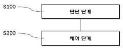
본 발명의 일 실시예에 따른 EPS 시스템의 제어 방법은 전자파 간섭에 의한 온도 오류에 대응하기 위한 제어 방법으로서, ECU(2)에 의해 수행될 수 있으며, S100 및 S200를 포함할 수 있다.The control method of the EPS system according to an exemplary embodiment of the present invention is a control method for responding to a temperature error caused by electromagnetic interference, and may be performed by the
먼저, S100은 판단 단계로서, 정상 상황 또는 비상 상황 중에 어느 한 상황의 발생을 판단한다. 또한, S200은 제어 단계로서, S100에서 판단된 상황에 따라 정상 동작 또는 비상 동작을 수행하여, 모터 구동신호의 출력을 제어한다.First, S100 is a determination step, and determines occurrence of any one of a normal situation and an emergency situation. In addition, S200 is a control step, and performs a normal operation or an emergency operation according to the situation determined in S100, to control the output of the motor drive signal.
정상 상황은 온도 센서에 의해 측정된 온도가 정상 조건 범위에 속하는 상황이다. 이 경우, 200에서, ECU(2)는 정상 동작을 수행한다. 즉, 정상 동작은 평상시와 같은 EPS 어시스트가 제공되도록 평상 시의 모터 구동신호가 출력되도록 제어하는 동작이다. 다만, 본 발명에서, ECU(2)는 정상 상황 및 정상 동작을 디폴드(default)의 상황 및 동작으로 판단 및 수행할 수 있다. 즉, ECU(2)는 비상 상황이 판단될 때까지는 계속해서 정상 상황으로 판단하여 정상 동작을 수행할 수 있다.The normal situation is a situation where the temperature measured by the temperature sensor falls within the normal condition range. In this case, at 200,
반면, 비상 상황은 S200에서 비상 동작이 수행되어야 하는 상황이다. 이때, 비상 동작은 기본적으로 종래의 EPS 시스템과 같이 제1 온도가 제1 기준 이상인 조건(이하, “제1 조건”이라 지칭함)에서 수행될 수 있다. 이에 따라, 비상 동작은 ECU(2)가 정상 상황 보다 줄어든 모터 출력 토크를 위한 모터 구동신호를 출력하도록 제어하는 동작이다. 이는 비상 상황의 경우, ECU(2)의 온도가 상승한 경우이므로, 모터 구동신호의 출력을 줄임으로써 모터 구동신호의 출력이 높아질수록 온도가 상승할 수 있는 ECU(2)의 온도를 줄이기 위함이다.On the other hand, an emergency situation is a situation in which an emergency operation should be performed in S200. In this case, the emergency operation may be basically performed under a condition in which the first temperature is equal to or greater than the first reference (hereinafter, referred to as “first condition”) as in the conventional EPS system. Accordingly, the emergency operation is an operation of controlling the
하지만, 온도 센서는 외부에서 유입되는 레이더파 등의 전자파 간섭에 의해 오작동될 수 있다. 그 결과, 제1 조건은 상술한 실험에서 나타난 바와 같이 전자파 간섭에 의해서도 나타날 수 있다. 이에 따라, 본 발명에서, ECU(2)는 제1 조건이라고 무조건 S100에서 비상 상황으로 판단하여 S200에서 비상 동작을 수행하는 것이 아니다. 오히려, 제1 조건이라도, ECU(2)는 제1 온도 및 제2 온도에 의한 기타 조건에 따라, S100에서 정상 상황 또는 비상 상황을 판단하여, S200에서 정상 동작 또는 비상 동작을 수행한다. 이때, 기타 조건은 상술한 실험의 결과로부터 도출될 수 있다. 이하, 이러한 기타 조건을 포함하는 다양한 조건에 대해서 설명하도록 한다.However, the temperature sensor may malfunction due to electromagnetic interference such as radar waves introduced from the outside. As a result, the first condition may also be caused by electromagnetic interference, as shown in the above experiment. Accordingly, in the present invention, the
도 5 및 도 6은 본 발명의 일 실시예에 따른 EPS 시스템의 제어 방법에서 정상 동작 또는 비상 동작을 수행하기 위한 다양한 조건을 판단하는 순서도를 나타낸다.5 and 6 are flowcharts for determining various conditions for performing normal operation or emergency operation in the control method of the EPS system according to an embodiment of the present invention.
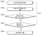
먼저, ECU1가 마스터로 동작 중일 때(S101), 제1 온도 및 제2 온도를 검출한다(S102). 이때, 제1 온도 및 제2 온도는 짧은 시간(예를 들어, 1ms 내지 100ms) 동안의 평균값일 수 있다.First, when ECU1 is operating as a master (S101), the first temperature and the second temperature are detected (S102). In this case, the first temperature and the second temperature may be average values for a short time (for example, 1 ms to 100 ms).
이후, 제1 조건을 만족하는지를 판단한다(S103). S103에서 제1 조건을 만족하는 경우, 즉 제1 온도가 제1 기준 이상인 경우, 제2 온도가 제1 온도 보다 높은 조건(이하, “제2 조건”이라 지칭함)인지를 판단한다(S104). S103에서 제1 조건을 만족하지 않는 경우, 즉 제1 온도가 제1 기준 미만인 경우, S101 또는 S102를 다시 수행하면서 여전히 정상 상황인 것으로 판단하여 계속해서 정상 동작을 수행할 수 있다.Thereafter, it is determined whether the first condition is satisfied (S103). When the first condition is satisfied in S103, that is, when the first temperature is greater than or equal to the first reference, it is determined whether the second temperature is a condition higher than the first temperature (hereinafter referred to as a “second condition”) (S104). When the first condition is not satisfied at S103, that is, when the first temperature is less than the first reference, it may be determined that it is still normal while performing S101 or S102 again, and continue to perform normal operation.
제2 조건은 전자파 간섭에 의해 제2 온도가 제1 온도 보다 높게 되는 현상을 반영한 조건이다. 이에 따라, S104에서 제2 조건을 만족하는 경우, S101 또는 S102를 다시 수행하면서 여전히 정상 상황인 것으로 판단하여 계속해서 정상 동작을 수행할 수 있다. 반대로, S104에서 제2 조건을 만족하지 않는 경우, 즉 제1 온도가 제2 온도 이상인 경우, 비상 상황인 것으로 판단하여 비상 동작을 수행할 수 있다(S201).The second condition is a condition reflecting a phenomenon in which the second temperature becomes higher than the first temperature due to electromagnetic interference. Accordingly, when the second condition is satisfied in S104, while performing S101 or S102 again, it may be determined that the system is still in a normal state, and thus the normal operation may continue. On the contrary, when the second condition is not satisfied in S104, that is, when the first temperature is greater than or equal to the second temperature, it may be determined that the emergency situation is performed (S201).
한편, 도 6은 참조하면, 본 발명은 제1 조건을 만족하고 제1 온도가 제2 온도 보다 높더라도, 추가적인 조건을 더 판단할 수 있다. 즉, S104에서 제2 조건을 만족하는 경우, 제1 온도가 제2 기준(예를 들어, 50℃) 보다 큰 차이로 제2 온도 보다 높은 조건(이하, “제3 조건”이라 지칭함)인지를 판단한다(S105).Meanwhile, referring to FIG. 6, the present invention may further determine additional conditions even if the first condition is satisfied and the first temperature is higher than the second temperature. That is, when the second condition is satisfied in S104, it is determined whether the first temperature is a condition higher than the second temperature (hereinafter referred to as “third condition”) with a difference greater than the second criterion (for example, 50 ° C.). It is determined (S105).
제3 조건은 도 2의 온도 그래프에서는 나타나지 않았지만 제1 온도 센서가 전자파 간섭에 의해 오작동하여 현격한 높은 온도를 검출하는 경우를 반영하기 위한 조건이다. 이에 따라, S105에서 제3 조건을 만족하는 경우, S101 또는 S102를 다시 수행하면서 여전히 정상 상황인 것으로 판단하여 계속해서 정상 동작을 수행할 수 있다. 반대로, S105에서 제2 조건을 만족하지 않는 경우, 즉 제1 온도가 제2 온도 보다 제2 기준 미만으로 큰 경우, 비상 상황인 것으로 판단하여 비상 동작을 수행할 수 있다(S201).Although the third condition is not shown in the temperature graph of FIG. 2, the third condition is a condition for reflecting the case where the first temperature sensor malfunctions due to electromagnetic interference and detects a marked high temperature. Accordingly, in the case where the third condition is satisfied in S105, while performing S101 or S102 again, it may be determined that the system is still in a normal state, and thus the normal operation may be continued. On the contrary, when the second condition is not satisfied in S105, that is, when the first temperature is less than the second reference than the second temperature, it may be determined that the emergency situation is performed (S201).
한편, 전자파가 펄스파 형태인 레이더 펄스파인 경우, 제1 온도 및 제2 온도는 일정 이하의 간격으로 반복되는 다양한 펄스 형태로 나타나는 조건(이하, “제4 조건”이라 지칭함)을 만족하게 된다. 이 경우, 도면으로 따로 도시하지 않았지만, S104은 제2 조건을 만족하면서 동시에 제4 조건을 만족하는지를 판단할 수 있다. 이때, S104에서 제2 조건 및 제4 조건을 만족하는 경우, 정상 상황인 것으로 판단하여 정상 동작을 수행할 수 있다. 반대로, S104에서 제2 조건 및 제4 조건을 만족하지 않는 경우, 즉 제1 온도가 제2 온도 이상인 경우, 비상 상황인 것으로 판단하여 비상 동작을 수행할 수 있다(S201).On the other hand, when the electromagnetic wave is a radar pulse wave in the form of a pulse wave, the first temperature and the second temperature satisfy a condition (hereinafter referred to as "fourth condition") that appears in various pulse forms that are repeated at a predetermined interval or less. In this case, although not illustrated separately in the drawing, S104 may determine whether the fourth condition is satisfied while satisfying the second condition. In this case, when the second condition and the fourth condition are satisfied in S104, it may be determined to be a normal situation and normal operation may be performed. On the contrary, when the second condition and the fourth condition are not satisfied in S104, that is, when the first temperature is greater than or equal to the second temperature, it may be determined that the emergency situation is performed (S201).
다만, 제4 조건은 펄스 형태 내에서 제2 온도가 제1 온도 보다 높은 조건, 즉 펄스 형태 내에서 제2 조건을 만족하는 조건일 수 있다. 이는, 도 2에 도시된 바와 같이, 레이더 펄스파에서 나타나는 온도 오류에 따른 온도 그래프에서 가장 특징적인 조건일 수 있다.However, the fourth condition may be a condition in which the second temperature is higher than the first temperature in the pulse shape, that is, a condition satisfying the second condition in the pulse shape. This may be the most characteristic condition in the temperature graph according to the temperature error appearing in the radar pulse wave, as shown in FIG. 2.
S101 내지 S105 등과 같이, 상술한 제1 조건 내지 제4 조건을 판단하기 위한 조건은 S100에 포함될 수 있다. 또한, 도면으로 따로 도시하지 않은 정상 동작 수행 단계 및 S201은 S200에 포함될 수 있다.Like S101 to S105, the above conditions for determining the first to fourth conditions may be included in S100. In addition, the normal operation performing step and S201 not shown separately in the drawings may be included in S200.
본 발명의 상세한 설명에서는 구체적인 실시 예에 관하여 설명하였으나 본 발명의 범위에서 벗어나지 않는 한도 내에서 여러 가지 변형이 가능함은 물론이다. 그러므로 본 발명의 범위는 설명된 실시 예에 국한되지 않으며, 후술되는 청구범위 및 이 청구범위와 균등한 것들에 의해 정해져야 한다.In the detailed description of the present invention, specific embodiments have been described, but various modifications may be made without departing from the scope of the present invention. Therefore, the scope of the present invention should not be limited to the described embodiments, but should be defined by the following claims and their equivalents.
1: 센서부2: ECU
3: 구동부4: 모터1: sensor unit 2: ECU
3: drive unit 4: motor
Claims (10)
Translated fromKorean마스터로 작동 중인 전자 제어 장치의 제1 온도와 슬레이브로 작동 중인 전자 제어 장치의 제2 온도를 이용하여, 정상 동작이나 비상 동작을 수행하며,
상기 비상 동작은 상기 제1 온도가 제1 기준 이상인 제1 조건에서 동작하되, 정상 동작의 경우 보다 줄어든 모터 출력 토크를 위한 모터 구동신호를 출력하도록 제어하는 동작이며,
상기 제1 조건이더라도, 상기 제2 온도가 상기 제1 온도 보다 높은 제2 조건에서 정상 동작을 수행하는 것을 특징으로 하는 전동식 파워 스티어링 시스템.An electric power steering system including an electronic control device having a redundancy structure corresponding to a temperature error caused by electromagnetic interference,
Using the first temperature of the electronic control device operating as a master and the second temperature of the electronic control device operating as a slave, perform a normal operation or an emergency operation,
The emergency operation is an operation for operating under a first condition in which the first temperature is equal to or greater than a first reference, and outputting a motor driving signal for reduced motor output torque in the normal operation.
The electric power steering system of claim 1, wherein the electric power steering system performs a normal operation under a second condition in which the second temperature is higher than the first temperature.
상기 제1 조건이고 상기 제1 온도가 상기 제2 온도 보다 높더라도, 상기 제1 온도가 제2 기준 보다 큰 차이로 상기 제2 온도 보다 높은 제3 조건에서 정상 동작을 수행하는 것을 특징으로 하는 전동식 파워 스티어링 시스템.The method of claim 1,
Even if the first condition and the first temperature is higher than the second temperature, the electric motor performs a normal operation in the third condition higher than the second temperature with a difference greater than the second reference. Power steering system.
상기 전자파는 레이더 펄스파인 것을 특징으로 하는 전동식 파워 스티어링 시스템.The method of claim 1,
The electromagnetic wave is a radar pulse wave.
상기 제1 조건이더라도, 상기 제2 조건이면서 상기 제1 온도 및 상기 제2 온도가 일정 이하의 간격으로 반복되는 다양한 펄스 형태를 가지는 제4 조건에서 정상 동작을 수행하는 것을 특징으로 하는 전동식 파워 스티어링 시스템.The method of claim 3,
Even in the first condition, the electric power steering system performs the normal operation in the fourth condition having the various pulse forms in which the first temperature and the second temperature are repeated at a predetermined interval or less under the second condition. .
상기 제4 조건은 펄스 형태 내에서 상기 제2 조건을 만족하는 것을 특징으로 하는 전동식 파워 스티어링 시스템.The method of claim 4, wherein
And said fourth condition satisfies said second condition in pulse form.
마스터로 작동 중인 전자 제어 장치의 제1 온도와 슬레이브로 작동 중인 전자 제어 장치의 제2 온도를 이용하여, 정상 동작이나 비상 동작을 수행하는 제어 단계를 포함하며,
상기 비상 동작은 상기 제1 온도가 제1 기준 이상인 제1 조건에서 동작하되, 정상 동작의 경우 보다 줄어든 모터 출력 토크를 위한 모터 구동신호를 출력하도록 제어하는 동작이며,
상기 제어 단계는 상기 제1 조건이더라도, 제1 온도가 일정 이상이고 제1 온도가 제2 온도 보다 높은 제2 조건에서 정상 동작을 수행하는 단계를 포함하는 것을 특징으로 하는 전동식 파워 스티어링 시스템의 제어 방법.A control method of an electric power steering system including an electronic control unit (ECD) having a redundancy structure corresponding to a temperature error caused by electromagnetic interference,
A control step of performing a normal operation or an emergency operation by using the first temperature of the electronic control device operating as the master and the second temperature of the electronic control device operating as the slave;
The emergency operation is an operation for operating under a first condition in which the first temperature is equal to or greater than a first reference, and outputting a motor driving signal for reduced motor output torque in the normal operation.
The controlling step may include performing a normal operation under a second condition in which the first temperature is higher than a predetermined temperature and the first temperature is higher than the second temperature even in the first condition. .
상기 제어 단계는,
상기 제1 조건이고 상기 제1 온도가 상기 제2 온도 보다 높더라도, 상기 제1 온도가 제2 기준 보다 큰 차이로 상기 제2 온도 보다 높은 제3 조건에서 정상 동작을 수행하는 단계를 포함하는 것을 특징으로 하는 전동식 파워 스티어링 시스템의 제어 방법.The method of claim 6,
The control step,
Performing a normal operation under a third condition, wherein the first temperature is higher than the second temperature, with a difference greater than a second criterion, even if the first condition is higher than the second temperature. The control method of the electric power steering system characterized by the above-mentioned.
상기 전자파는 레이더 펄스파인 것을 특징으로 하는 전동식 파워 스티어링 시스템의 제어 방법.The method of claim 6,
The electromagnetic wave is a radar pulse wave control method of the electric power steering system.
상기 제어 단계는,
상기 제1 조건이더라도, 상기 제2 조건이면서 상기 제1 온도 및 상기 제2 온도가 일정 이하의 간격으로 반복되는 다양한 펄스 형태를 가지는 제4 조건에서 정상 동작을 수행하는 단계를 포함하는 것을 특징으로 하는 전동식 파워 스티어링 시스템의 제어 방법.The method of claim 8,
The control step,
And performing the normal operation even in the first condition, in the fourth condition having the various pulse shapes in which the first temperature and the second temperature are repeated at a predetermined interval or less while being the second condition. How to control the electric power steering system.
상기 제4 조건은 펄스 형태 내에서 상기 제2 조건을 만족하는 것을 특징으로 하는 전동식 파워 스티어링 시스템의 제어 방법.The method of claim 9,
And said fourth condition satisfies said second condition within a pulse shape.
Priority Applications (1)
| Application Number | Priority Date | Filing Date | Title |
|---|---|---|---|
| KR1020180157130AKR102078058B1 (en) | 2018-12-07 | 2018-12-07 | Electronic power steering system detecting temperature error due to electromagnetic interference and controlling method thereof |
Applications Claiming Priority (1)
| Application Number | Priority Date | Filing Date | Title |
|---|---|---|---|
| KR1020180157130AKR102078058B1 (en) | 2018-12-07 | 2018-12-07 | Electronic power steering system detecting temperature error due to electromagnetic interference and controlling method thereof |
Publications (1)
| Publication Number | Publication Date |
|---|---|
| KR102078058B1true KR102078058B1 (en) | 2020-02-17 |
Family
ID=69670528
Family Applications (1)
| Application Number | Title | Priority Date | Filing Date |
|---|---|---|---|
| KR1020180157130AActiveKR102078058B1 (en) | 2018-12-07 | 2018-12-07 | Electronic power steering system detecting temperature error due to electromagnetic interference and controlling method thereof |
Country Status (1)
| Country | Link |
|---|---|
| KR (1) | KR102078058B1 (en) |
Cited By (1)
| Publication number | Priority date | Publication date | Assignee | Title |
|---|---|---|---|---|
| CN114636886A (en)* | 2022-05-18 | 2022-06-17 | 中汽研(天津)汽车工程研究院有限公司 | Automobile electromagnetic compatibility radio frequency anti-interference test method based on auxiliary steering system |
Citations (8)
| Publication number | Priority date | Publication date | Assignee | Title |
|---|---|---|---|---|
| JPH1153207A (en)* | 1997-07-30 | 1999-02-26 | Koyo Seiko Co Ltd | Controller for vehicle |
| JPH1178943A (en)* | 1997-09-12 | 1999-03-23 | Honda Motor Co Ltd | Electric power steering device |
| EP0917403A2 (en)* | 1997-11-14 | 1999-05-19 | Lg Electronics Inc. | Error-compensation for temperature detection in a microwave oven |
| JP2003011832A (en)* | 2001-06-28 | 2003-01-15 | Koyo Seiko Co Ltd | Electric power steering device |
| JP2003019973A (en)* | 2001-07-10 | 2003-01-21 | Omron Corp | Control unit |
| JP2007030678A (en)* | 2005-07-27 | 2007-02-08 | Toyota Motor Corp | Vehicle steering assist device |
| JP2009051255A (en)* | 2007-08-23 | 2009-03-12 | Nsk Ltd | Control device for electric power steering device |
| JP2015081013A (en)* | 2013-10-23 | 2015-04-27 | 三菱電機株式会社 | Electric power steering controller |
- 2018
- 2018-12-07KRKR1020180157130Apatent/KR102078058B1/enactiveActive
Patent Citations (8)
| Publication number | Priority date | Publication date | Assignee | Title |
|---|---|---|---|---|
| JPH1153207A (en)* | 1997-07-30 | 1999-02-26 | Koyo Seiko Co Ltd | Controller for vehicle |
| JPH1178943A (en)* | 1997-09-12 | 1999-03-23 | Honda Motor Co Ltd | Electric power steering device |
| EP0917403A2 (en)* | 1997-11-14 | 1999-05-19 | Lg Electronics Inc. | Error-compensation for temperature detection in a microwave oven |
| JP2003011832A (en)* | 2001-06-28 | 2003-01-15 | Koyo Seiko Co Ltd | Electric power steering device |
| JP2003019973A (en)* | 2001-07-10 | 2003-01-21 | Omron Corp | Control unit |
| JP2007030678A (en)* | 2005-07-27 | 2007-02-08 | Toyota Motor Corp | Vehicle steering assist device |
| JP2009051255A (en)* | 2007-08-23 | 2009-03-12 | Nsk Ltd | Control device for electric power steering device |
| JP2015081013A (en)* | 2013-10-23 | 2015-04-27 | 三菱電機株式会社 | Electric power steering controller |
Cited By (2)
| Publication number | Priority date | Publication date | Assignee | Title |
|---|---|---|---|---|
| CN114636886A (en)* | 2022-05-18 | 2022-06-17 | 中汽研(天津)汽车工程研究院有限公司 | Automobile electromagnetic compatibility radio frequency anti-interference test method based on auxiliary steering system |
| CN114636886B (en)* | 2022-05-18 | 2022-08-09 | 中汽研(天津)汽车工程研究院有限公司 | A test method for automotive electromagnetic compatibility radio frequency immunity based on assisted steering system |
Similar Documents
| Publication | Publication Date | Title |
|---|---|---|
| US11643095B2 (en) | Electronic control device, control system, and reset determination method | |
| US10525957B2 (en) | Brake-by-wire system | |
| CN110168506B (en) | Control system for a motor vehicle, and method for controlling a motor vehicle | |
| US10501063B2 (en) | Brake-by-wire system | |
| US20140358375A1 (en) | Actuator control apparatus | |
| US20180056961A1 (en) | Brake-by-wire system | |
| US10507816B2 (en) | Brake-by-wire system | |
| EP3196096B1 (en) | Electric power steering device | |
| US20180056964A1 (en) | Brake-by-wire system | |
| US10077070B2 (en) | Power-source voltage diagnostic device of electric power steering apparatus | |
| KR102078058B1 (en) | Electronic power steering system detecting temperature error due to electromagnetic interference and controlling method thereof | |
| EP2216629B1 (en) | Sensor apparatus | |
| KR102690454B1 (en) | Redundancy system of vehicle and, apparatus and method for supplying power thereof | |
| KR20200109808A (en) | System for assisting steering, Apparatus for controlling steering and Method thereof | |
| WO2025185718A1 (en) | Electric power steering system, control method and device therefor, and vehicle | |
| US10919394B2 (en) | Power system and method of controlling the same | |
| US20190077443A1 (en) | Method and apparatus for fail-safe electric power steering | |
| KR20170065430A (en) | Apparatus for complex sensing | |
| KR20130011843A (en) | Apparatus for controlling motor drive power steering in vehicle and method | |
| JP4539923B2 (en) | Control device for electric power steering device | |
| KR101835783B1 (en) | Power train control unit for vehicle | |
| KR100646395B1 (en) | Fail-safe control method of electronically controlled power steering system | |
| US6738700B2 (en) | Method for conforming a signal to a fault requirement using a command limiting scheme | |
| JP2015150998A (en) | Steer-by-wire steering device | |
| KR20200085037A (en) | Electronic power steering system and controlling method thereof |
Legal Events
| Date | Code | Title | Description |
|---|---|---|---|
| PA0109 | Patent application | St.27 status event code:A-0-1-A10-A12-nap-PA0109 | |
| PA0201 | Request for examination | St.27 status event code:A-1-2-D10-D11-exm-PA0201 | |
| D13-X000 | Search requested | St.27 status event code:A-1-2-D10-D13-srh-X000 | |
| D14-X000 | Search report completed | St.27 status event code:A-1-2-D10-D14-srh-X000 | |
| PE0701 | Decision of registration | St.27 status event code:A-1-2-D10-D22-exm-PE0701 | |
| GRNT | Written decision to grant | ||
| PR0701 | Registration of establishment | St.27 status event code:A-2-4-F10-F11-exm-PR0701 | |
| PR1002 | Payment of registration fee | St.27 status event code:A-2-2-U10-U11-oth-PR1002 Fee payment year number:1 | |
| PG1601 | Publication of registration | St.27 status event code:A-4-4-Q10-Q13-nap-PG1601 | |
| PN2301 | Change of applicant | St.27 status event code:A-5-5-R10-R13-asn-PN2301 St.27 status event code:A-5-5-R10-R11-asn-PN2301 | |
| PN2301 | Change of applicant | St.27 status event code:A-5-5-R10-R13-asn-PN2301 St.27 status event code:A-5-5-R10-R11-asn-PN2301 | |
| PN2301 | Change of applicant | St.27 status event code:A-5-5-R10-R13-asn-PN2301 St.27 status event code:A-5-5-R10-R11-asn-PN2301 | |
| PR1001 | Payment of annual fee | St.27 status event code:A-4-4-U10-U11-oth-PR1001 Fee payment year number:4 | |
| PR1001 | Payment of annual fee | St.27 status event code:A-4-4-U10-U11-oth-PR1001 Fee payment year number:5 | |
| PR1001 | Payment of annual fee | St.27 status event code:A-4-4-U10-U11-oth-PR1001 Fee payment year number:6 | |
| R18-X000 | Changes to party contact information recorded | St.27 status event code:A-5-5-R10-R18-oth-X000 |