KR102075699B1 - Method and machine for manufacturing green pieces made of ceramic and/or metallic material by the technique of additive manufacturing - Google Patents
Method and machine for manufacturing green pieces made of ceramic and/or metallic material by the technique of additive manufacturingDownload PDFInfo
- Publication number
- KR102075699B1 KR102075699B1KR1020180081096AKR20180081096AKR102075699B1KR 102075699 B1KR102075699 B1KR 102075699B1KR 1020180081096 AKR1020180081096 AKR 1020180081096AKR 20180081096 AKR20180081096 AKR 20180081096AKR 102075699 B1KR102075699 B1KR 102075699B1
- Authority
- KR
- South Korea
- Prior art keywords
- support sheet
- tray
- layer
- green piece
- sheet
- Prior art date
- Legal status (The legal status is an assumption and is not a legal conclusion. Google has not performed a legal analysis and makes no representation as to the accuracy of the status listed.)
- Expired - Fee Related
Links
Images


Classifications
- B—PERFORMING OPERATIONS; TRANSPORTING
- B28—WORKING CEMENT, CLAY, OR STONE
- B28B—SHAPING CLAY OR OTHER CERAMIC COMPOSITIONS; SHAPING SLAG; SHAPING MIXTURES CONTAINING CEMENTITIOUS MATERIAL, e.g. PLASTER
- B28B1/00—Producing shaped prefabricated articles from the material
- B28B1/001—Rapid manufacturing of 3D objects by additive depositing, agglomerating or laminating of material
- B—PERFORMING OPERATIONS; TRANSPORTING
- B29—WORKING OF PLASTICS; WORKING OF SUBSTANCES IN A PLASTIC STATE IN GENERAL
- B29C—SHAPING OR JOINING OF PLASTICS; SHAPING OF MATERIAL IN A PLASTIC STATE, NOT OTHERWISE PROVIDED FOR; AFTER-TREATMENT OF THE SHAPED PRODUCTS, e.g. REPAIRING
- B29C64/00—Additive manufacturing, i.e. manufacturing of three-dimensional [3D] objects by additive deposition, additive agglomeration or additive layering, e.g. by 3D printing, stereolithography or selective laser sintering
- B29C64/20—Apparatus for additive manufacturing; Details thereof or accessories therefor
- B29C64/245—Platforms or substrates
- B—PERFORMING OPERATIONS; TRANSPORTING
- B28—WORKING CEMENT, CLAY, OR STONE
- B28B—SHAPING CLAY OR OTHER CERAMIC COMPOSITIONS; SHAPING SLAG; SHAPING MIXTURES CONTAINING CEMENTITIOUS MATERIAL, e.g. PLASTER
- B28B13/00—Feeding the unshaped material to moulds or apparatus for producing shaped articles; Discharging shaped articles from such moulds or apparatus
- B28B13/02—Feeding the unshaped material to moulds or apparatus for producing shaped articles
- B—PERFORMING OPERATIONS; TRANSPORTING
- B22—CASTING; POWDER METALLURGY
- B22F—WORKING METALLIC POWDER; MANUFACTURE OF ARTICLES FROM METALLIC POWDER; MAKING METALLIC POWDER; APPARATUS OR DEVICES SPECIALLY ADAPTED FOR METALLIC POWDER
- B22F1/00—Metallic powder; Treatment of metallic powder, e.g. to facilitate working or to improve properties
- B22F1/10—Metallic powder containing lubricating or binding agents; Metallic powder containing organic material
- B22F1/102—Metallic powder coated with organic material
- B—PERFORMING OPERATIONS; TRANSPORTING
- B22—CASTING; POWDER METALLURGY
- B22F—WORKING METALLIC POWDER; MANUFACTURE OF ARTICLES FROM METALLIC POWDER; MAKING METALLIC POWDER; APPARATUS OR DEVICES SPECIALLY ADAPTED FOR METALLIC POWDER
- B22F10/00—Additive manufacturing of workpieces or articles from metallic powder
- B22F10/10—Formation of a green body
- B22F10/12—Formation of a green body by photopolymerisation, e.g. stereolithography [SLA] or digital light processing [DLP]
- B—PERFORMING OPERATIONS; TRANSPORTING
- B22—CASTING; POWDER METALLURGY
- B22F—WORKING METALLIC POWDER; MANUFACTURE OF ARTICLES FROM METALLIC POWDER; MAKING METALLIC POWDER; APPARATUS OR DEVICES SPECIALLY ADAPTED FOR METALLIC POWDER
- B22F12/00—Apparatus or devices specially adapted for additive manufacturing; Auxiliary means for additive manufacturing; Combinations of additive manufacturing apparatus or devices with other processing apparatus or devices
- B22F12/30—Platforms or substrates
- B22F3/1055—
- B—PERFORMING OPERATIONS; TRANSPORTING
- B22—CASTING; POWDER METALLURGY
- B22F—WORKING METALLIC POWDER; MANUFACTURE OF ARTICLES FROM METALLIC POWDER; MAKING METALLIC POWDER; APPARATUS OR DEVICES SPECIALLY ADAPTED FOR METALLIC POWDER
- B22F3/00—Manufacture of workpieces or articles from metallic powder characterised by the manner of compacting or sintering; Apparatus specially adapted therefor ; Presses and furnaces
- B22F3/24—After-treatment of workpieces or articles
- B—PERFORMING OPERATIONS; TRANSPORTING
- B28—WORKING CEMENT, CLAY, OR STONE
- B28B—SHAPING CLAY OR OTHER CERAMIC COMPOSITIONS; SHAPING SLAG; SHAPING MIXTURES CONTAINING CEMENTITIOUS MATERIAL, e.g. PLASTER
- B28B17/00—Details of, or accessories for, apparatus for shaping the material; Auxiliary measures taken in connection with such shaping
- B—PERFORMING OPERATIONS; TRANSPORTING
- B29—WORKING OF PLASTICS; WORKING OF SUBSTANCES IN A PLASTIC STATE IN GENERAL
- B29C—SHAPING OR JOINING OF PLASTICS; SHAPING OF MATERIAL IN A PLASTIC STATE, NOT OTHERWISE PROVIDED FOR; AFTER-TREATMENT OF THE SHAPED PRODUCTS, e.g. REPAIRING
- B29C64/00—Additive manufacturing, i.e. manufacturing of three-dimensional [3D] objects by additive deposition, additive agglomeration or additive layering, e.g. by 3D printing, stereolithography or selective laser sintering
- B29C64/20—Apparatus for additive manufacturing; Details thereof or accessories therefor
- B29C64/205—Means for applying layers
- B29C64/223—Foils or films, e.g. for transferring layers of building material from one working station to another
- B—PERFORMING OPERATIONS; TRANSPORTING
- B29—WORKING OF PLASTICS; WORKING OF SUBSTANCES IN A PLASTIC STATE IN GENERAL
- B29C—SHAPING OR JOINING OF PLASTICS; SHAPING OF MATERIAL IN A PLASTIC STATE, NOT OTHERWISE PROVIDED FOR; AFTER-TREATMENT OF THE SHAPED PRODUCTS, e.g. REPAIRING
- B29C67/00—Shaping techniques not covered by groups B29C39/00 - B29C65/00, B29C70/00 or B29C73/00
- B29C67/24—Shaping techniques not covered by groups B29C39/00 - B29C65/00, B29C70/00 or B29C73/00 characterised by the choice of material
- B29C67/242—Moulding mineral aggregates bonded with resin, e.g. resin concrete
- B29C67/243—Moulding mineral aggregates bonded with resin, e.g. resin concrete for making articles of definite length
- B—PERFORMING OPERATIONS; TRANSPORTING
- B33—ADDITIVE MANUFACTURING TECHNOLOGY
- B33Y—ADDITIVE MANUFACTURING, i.e. MANUFACTURING OF THREE-DIMENSIONAL [3-D] OBJECTS BY ADDITIVE DEPOSITION, ADDITIVE AGGLOMERATION OR ADDITIVE LAYERING, e.g. BY 3-D PRINTING, STEREOLITHOGRAPHY OR SELECTIVE LASER SINTERING
- B33Y30/00—Apparatus for additive manufacturing; Details thereof or accessories therefor
- B—PERFORMING OPERATIONS; TRANSPORTING
- B33—ADDITIVE MANUFACTURING TECHNOLOGY
- B33Y—ADDITIVE MANUFACTURING, i.e. MANUFACTURING OF THREE-DIMENSIONAL [3-D] OBJECTS BY ADDITIVE DEPOSITION, ADDITIVE AGGLOMERATION OR ADDITIVE LAYERING, e.g. BY 3-D PRINTING, STEREOLITHOGRAPHY OR SELECTIVE LASER SINTERING
- B33Y40/00—Auxiliary operations or equipment, e.g. for material handling
- B—PERFORMING OPERATIONS; TRANSPORTING
- B33—ADDITIVE MANUFACTURING TECHNOLOGY
- B33Y—ADDITIVE MANUFACTURING, i.e. MANUFACTURING OF THREE-DIMENSIONAL [3-D] OBJECTS BY ADDITIVE DEPOSITION, ADDITIVE AGGLOMERATION OR ADDITIVE LAYERING, e.g. BY 3-D PRINTING, STEREOLITHOGRAPHY OR SELECTIVE LASER SINTERING
- B33Y70/00—Materials specially adapted for additive manufacturing
- C—CHEMISTRY; METALLURGY
- C04—CEMENTS; CONCRETE; ARTIFICIAL STONE; CERAMICS; REFRACTORIES
- C04B—LIME, MAGNESIA; SLAG; CEMENTS; COMPOSITIONS THEREOF, e.g. MORTARS, CONCRETE OR LIKE BUILDING MATERIALS; ARTIFICIAL STONE; CERAMICS; REFRACTORIES; TREATMENT OF NATURAL STONE
- C04B35/00—Shaped ceramic products characterised by their composition; Ceramics compositions; Processing powders of inorganic compounds preparatory to the manufacturing of ceramic products
- C04B35/622—Forming processes; Processing powders of inorganic compounds preparatory to the manufacturing of ceramic products
- C04B35/626—Preparing or treating the powders individually or as batches ; preparing or treating macroscopic reinforcing agents for ceramic products, e.g. fibres; mechanical aspects section B
- C04B35/63—Preparing or treating the powders individually or as batches ; preparing or treating macroscopic reinforcing agents for ceramic products, e.g. fibres; mechanical aspects section B using additives specially adapted for forming the products, e.g.. binder binders
- C04B35/632—Organic additives
- C04B35/634—Polymers
- C—CHEMISTRY; METALLURGY
- C04—CEMENTS; CONCRETE; ARTIFICIAL STONE; CERAMICS; REFRACTORIES
- C04B—LIME, MAGNESIA; SLAG; CEMENTS; COMPOSITIONS THEREOF, e.g. MORTARS, CONCRETE OR LIKE BUILDING MATERIALS; ARTIFICIAL STONE; CERAMICS; REFRACTORIES; TREATMENT OF NATURAL STONE
- C04B35/00—Shaped ceramic products characterised by their composition; Ceramics compositions; Processing powders of inorganic compounds preparatory to the manufacturing of ceramic products
- C04B35/622—Forming processes; Processing powders of inorganic compounds preparatory to the manufacturing of ceramic products
- C04B35/64—Burning or sintering processes
- B—PERFORMING OPERATIONS; TRANSPORTING
- B22—CASTING; POWDER METALLURGY
- B22F—WORKING METALLIC POWDER; MANUFACTURE OF ARTICLES FROM METALLIC POWDER; MAKING METALLIC POWDER; APPARATUS OR DEVICES SPECIALLY ADAPTED FOR METALLIC POWDER
- B22F10/00—Additive manufacturing of workpieces or articles from metallic powder
- B22F10/60—Treatment of workpieces or articles after build-up
- B22F10/68—Cleaning or washing
- B—PERFORMING OPERATIONS; TRANSPORTING
- B22—CASTING; POWDER METALLURGY
- B22F—WORKING METALLIC POWDER; MANUFACTURE OF ARTICLES FROM METALLIC POWDER; MAKING METALLIC POWDER; APPARATUS OR DEVICES SPECIALLY ADAPTED FOR METALLIC POWDER
- B22F12/00—Apparatus or devices specially adapted for additive manufacturing; Auxiliary means for additive manufacturing; Combinations of additive manufacturing apparatus or devices with other processing apparatus or devices
- B22F12/60—Planarisation devices; Compression devices
- B22F12/67—Blades
- B22F2003/1057—
- B—PERFORMING OPERATIONS; TRANSPORTING
- B22—CASTING; POWDER METALLURGY
- B22F—WORKING METALLIC POWDER; MANUFACTURE OF ARTICLES FROM METALLIC POWDER; MAKING METALLIC POWDER; APPARATUS OR DEVICES SPECIALLY ADAPTED FOR METALLIC POWDER
- B22F3/00—Manufacture of workpieces or articles from metallic powder characterised by the manner of compacting or sintering; Apparatus specially adapted therefor ; Presses and furnaces
- B22F3/24—After-treatment of workpieces or articles
- B22F2003/247—Removing material: carving, cleaning, grinding, hobbing, honing, lapping, polishing, milling, shaving, skiving, turning the surface
- B—PERFORMING OPERATIONS; TRANSPORTING
- B29—WORKING OF PLASTICS; WORKING OF SUBSTANCES IN A PLASTIC STATE IN GENERAL
- B29C—SHAPING OR JOINING OF PLASTICS; SHAPING OF MATERIAL IN A PLASTIC STATE, NOT OTHERWISE PROVIDED FOR; AFTER-TREATMENT OF THE SHAPED PRODUCTS, e.g. REPAIRING
- B29C64/00—Additive manufacturing, i.e. manufacturing of three-dimensional [3D] objects by additive deposition, additive agglomeration or additive layering, e.g. by 3D printing, stereolithography or selective laser sintering
- B29C64/10—Processes of additive manufacturing
- B29C64/106—Processes of additive manufacturing using only liquids or viscous materials, e.g. depositing a continuous bead of viscous material
- B29C64/124—Processes of additive manufacturing using only liquids or viscous materials, e.g. depositing a continuous bead of viscous material using layers of liquid which are selectively solidified
- B—PERFORMING OPERATIONS; TRANSPORTING
- B29—WORKING OF PLASTICS; WORKING OF SUBSTANCES IN A PLASTIC STATE IN GENERAL
- B29C—SHAPING OR JOINING OF PLASTICS; SHAPING OF MATERIAL IN A PLASTIC STATE, NOT OTHERWISE PROVIDED FOR; AFTER-TREATMENT OF THE SHAPED PRODUCTS, e.g. REPAIRING
- B29C64/00—Additive manufacturing, i.e. manufacturing of three-dimensional [3D] objects by additive deposition, additive agglomeration or additive layering, e.g. by 3D printing, stereolithography or selective laser sintering
- B29C64/20—Apparatus for additive manufacturing; Details thereof or accessories therefor
- B29C64/205—Means for applying layers
- B29C64/214—Doctor blades
- B—PERFORMING OPERATIONS; TRANSPORTING
- B33—ADDITIVE MANUFACTURING TECHNOLOGY
- B33Y—ADDITIVE MANUFACTURING, i.e. MANUFACTURING OF THREE-DIMENSIONAL [3-D] OBJECTS BY ADDITIVE DEPOSITION, ADDITIVE AGGLOMERATION OR ADDITIVE LAYERING, e.g. BY 3-D PRINTING, STEREOLITHOGRAPHY OR SELECTIVE LASER SINTERING
- B33Y10/00—Processes of additive manufacturing
- Y—GENERAL TAGGING OF NEW TECHNOLOGICAL DEVELOPMENTS; GENERAL TAGGING OF CROSS-SECTIONAL TECHNOLOGIES SPANNING OVER SEVERAL SECTIONS OF THE IPC; TECHNICAL SUBJECTS COVERED BY FORMER USPC CROSS-REFERENCE ART COLLECTIONS [XRACs] AND DIGESTS
- Y02—TECHNOLOGIES OR APPLICATIONS FOR MITIGATION OR ADAPTATION AGAINST CLIMATE CHANGE
- Y02P—CLIMATE CHANGE MITIGATION TECHNOLOGIES IN THE PRODUCTION OR PROCESSING OF GOODS
- Y02P10/00—Technologies related to metal processing
- Y02P10/25—Process efficiency
Landscapes
- Engineering & Computer Science (AREA)
- Chemical & Material Sciences (AREA)
- Manufacturing & Machinery (AREA)
- Materials Engineering (AREA)
- Mechanical Engineering (AREA)
- Ceramic Engineering (AREA)
- Physics & Mathematics (AREA)
- Optics & Photonics (AREA)
- Structural Engineering (AREA)
- Inorganic Chemistry (AREA)
- Organic Chemistry (AREA)
- Devices For Post-Treatments, Processing, Supply, Discharge, And Other Processes (AREA)
- Producing Shaped Articles From Materials (AREA)
- Laminated Bodies (AREA)
- Plasma & Fusion (AREA)
- Thermal Sciences (AREA)
- Fluid Mechanics (AREA)
- Powder Metallurgy (AREA)
Abstract
Translated fromKoreanDescription
Translated fromKorean본 발명은 최종 세라믹 및/또는 금속 피스를 얻기 위해 세정, 탈바인딩 및 소결 공정을 거치도록 의도된 그린 피스를 적층 가공에 의해 제조하기 위한 방법 및 머신에 관한 것이다.The present invention relates to a method and a machine for producing green pieces by additive manufacturing intended to undergo cleaning, debinding and sintering processes to obtain the final ceramic and / or metal pieces.
스테레오리소그래피(stereolithography)로도 칭하는 적층 가공 기술은 일반적으로 그린 피스를 제공하기 위하여 이하의 단계들을 포함한다:The additive manufacturing technique, also called stereolithography, generally includes the following steps to provide a green piece:
컴퓨터 보조 설계에 의해, 제조될 피스의 컴퓨터 모델을 구축하는 단계 - 모델의 크기는 피스의 제조 동안 세라믹 또는 금속 재료의 수축을 예상하여 제조될 피스의 크기 보다 약간 더 큼 - ; 및By computer aided design, building a computer model of the piece to be manufactured, the size of the model being slightly larger than the size of the piece to be manufactured in anticipation of shrinkage of the ceramic or metal material during manufacture of the piece; And
적층 가공의 기술을 이용하여 피스를 제조하는 단계로서:As a step of manufacturing a piece using the technique of additive manufacturing:
적어도 하나의 세라믹 또는 금속 재료, 적어도 하나의 광경화성 모노머 및/또는 올리고머, 적어도 하나의 광개시제 및, 경우에 따라, 적어도 하나의 가소제 및/또는 적어도 하나의 용매 및/또는 적어도 하나의 분산제를 포함하는 광경화성 조성물의 제1 층을 경질 지지체 상에 형성하는 단계;At least one ceramic or metal material, at least one photocurable monomer and / or oligomer, at least one photoinitiator and, optionally, at least one plasticizer and / or at least one solvent and / or at least one dispersant. Forming a first layer of the photocurable composition on the rigid support;
상기 층에 대해 상기 모델로부터 규정되는 패턴에 따른(상기 층의 자유면의 레이저 스캐닝에 의한 또는 다이오드 투사 시스템에 의한) 조사에 의해 상기 광경화성 조성물의 제1 층을 경화하여 제1 스테이지를 형성하는 단계;Curing the first layer of the photocurable composition by irradiation (by laser scanning of the free surface of the layer or by a diode projection system) according to a pattern defined from the model for the layer to form a first stage step;
상기 제1 스테이지 상에 상기 광경화성 조성물의 제2 층을 형성하는 단계;Forming a second layer of the photocurable composition on the first stage;
상기 층에 대해 규정된 패턴에 따른 조사에 의해 상기 광경화성 조성물의 제2 층을 경화하여 제2 스테이지를 형성하는 단계 - 이 조사는 제1 층과 동일한 방식으로 수행됨 -Curing the second layer of the photocurable composition by irradiation according to a pattern defined for the layer to form a second stage, the irradiation being performed in the same manner as the first layer
선택적으로는, 상술한 단계들은 그린 피스가 얻어질 때까지 반복됨.Optionally, the above steps are repeated until a green piece is obtained.
다음으로, 위에서 나타낸 것처럼, 완성된 피스를 얻기 위해서, 그린 피스는 비경화된 조성물을 제거하기 위하여 세정되고; 세정된 그린 피스가 탈바인딩되고; 또한 탈바인딩된 그린 피스가 소결되어, 완성된 피스를 얻는다.Next, as shown above, to obtain the finished piece, the green piece is washed to remove the uncured composition; The cleaned green piece is debound; The debound green piece is also sintered to obtain the finished piece.
상기 피스는 페이스트 공정 또는 액상 공정으로 제조될 수 있다.The piece may be prepared by a paste process or a liquid process.
페이스트 공정에 의한 제조에서, 광경화성 조성물은 페이스트 형태로 존재하며, 그 점도는 특히 1 Pa.s. 에서 제로 전단 속도(zero shear rate)를 갖는 무한대까지 다양하며, 경질 지지체는 상기 페이스트 외에도 설치될 피스의 상이한 층들을 지지하는 작업 트레이이며, 층들의 각각은 일반적으로 작업 트레이를 낮추고 미리 규정된 페이스트 두께로 확산시킴에 의해 형성된다. 페이스트 공급분은 피스톤을 이용하여 각각의 층에 소정 페이스트 양이 자동으로 비워지는 콘테이너 내에 저장된다. 이는 작업 트레이에 의해 사전에 낮춰진 설치될 피스의 상부층 상에서 확산되는 페이스트 비드(bead)의 생성을 초래한다. 각각의 층은 일반적으로 예를 들면 직선 수평 방향을 따라 전진함에 의해 작업 트레이의 작업 표면을 스위프하는 스크레이핑 블레이드에 의한 스크레이핑에 의해 확산된다.In preparation by the paste process, the photocurable composition is in the form of a paste, the viscosity of which is in particular 1 Pa.s. From infinity to zero shear rate, the rigid support is a work tray that supports different layers of pieces to be installed in addition to the paste, each of which typically lowers the work tray and has a predefined paste thickness It is formed by diffusion. The paste feed is stored in a container in which a predetermined amount of paste is automatically emptied in each layer using a piston. This results in the production of paste beads which are spread on the upper layer of the piece to be installed which has been lowered by the work tray in advance. Each layer is generally diffused by scraping with a scraping blade sweeping the working surface of the working tray, for example by advancing along a straight horizontal direction.
액상 공정에 의한 제조에서, 광경화성 조성물은 낮은 점도를 갖는 슬러리의 형태로 존재한다.In the preparation by liquid phase process, the photocurable composition is in the form of a slurry having a low viscosity.
액상 공정에 의한 제1 실시예에서, 경질 지지체는 상기 슬러리의 층으로 덮기 위하여 광경화성 슬러리의 배스(bath) 내로 낮춰지는 트레이로서, 다음으로 층은 상술한 것처럼 조사에 의해 경화된다. 이 제1 층 상에, 다른 층들 각각이 배스 내의 트레이를 단계별로 낮춤에 의해 연속적으로 형성되어, 설치될 피스의 상부 스테이지는 추후 조사되는 논의중인 층을 형성하기 위하여 광경화성 슬러리의 자유 표면 아래로 낮추게 된다.In a first embodiment by a liquid phase process, the hard support is a tray lowered into a bath of photocurable slurry to cover with the layer of the slurry, and then the layer is cured by irradiation as described above. On this first layer, each of the other layers is successively formed by stepping down the tray in the bath so that the upper stage of the piece to be installed is below the free surface of the photocurable slurry to form the layer under discussion to be investigated later. Will be lowered.
액상 공정의 제2 실시예에서, 광경화성 슬러리는 조사를 위하여 투명한 하부를 갖는 컨테이너 내에 수용되며, 피스는 단계별로 상승되는 트레이인 경질 지지체 상에 유지된다. 따라서, 하부층은 먼저 경화되고, 다음으로 트레이는 한단계 상승되어 슬러리가 추후 경화되는 신규 층을 구성하도록 하며, 동작은 각각의 층에 대해 반복된다.In a second embodiment of the liquid phase process, the photocurable slurry is contained in a container having a transparent bottom for irradiation, and the pieces are held on a rigid support, which is a stepped tray. Thus, the bottom layer is cured first and then the tray is raised one step to make up a new layer where the slurry is subsequently cured, and the operation is repeated for each layer.
액상 공정의 제3 실시예에서, 광경화성 슬러리는 조사를 위해 투명한 필름 상의 층으로 확산되며, 이 필름은 수평으로 펼쳐질(unrolled) 수 있다. 피스는 필름을 통과하는 조사에 의해 경화되는 층과 접촉하도록 낮춰지는 경질 트레이 상에 형성된다. 신규 광경화성 층으로 코팅된 신규 필름 세그먼트는 다음으로 펼쳐지고, 동작은 피스가 완전히 완성될 때까지 반복된다.In a third embodiment of the liquid phase process, the photocurable slurry is diffused into a layer on a transparent film for irradiation, which film can be unrolled horizontally. The pieces are formed on a hard tray that is lowered to contact the layer that is cured by irradiation through the film. The new film segment coated with the new photocurable layer is then unfolded and the operation repeated until the piece is completely complete.
작업 표면 즉 경질 작업 트레이(페이스트 공정 및 액상 공정의 상술한 제1 실시예의 경우에는 작업 트레이의 상부면, 액상 공정의 상술한 제2 실시예 및 제3 실시예의 경우에는 트레이의 하부면)와 층들의 적층에 의해 설치되는 피스 사이에 우수한 바인딩을 제공하는 것이 중요하다.A working surface, i.e., a hard working tray (the upper surface of the working tray in the first embodiment of the pasting process and the liquid phase process, the lower surface of the tray in the second and third embodiments of the liquid phase process) and a layer It is important to provide good binding between the pieces installed by the lamination.
피스의 제조를 촉진하기 위하여, 경질 트레이 상에 설치될 피스의 구속력을 가능한 강하게 할 필요가 있다. 구속력이 낮은 경우, 피스는 그 제조 동안 움직일 가능성이 있다. 그러한 위험은 스크레이핑 시스템이 층들을 적층하기 위하여 이용되는 경우(페이스티 공정)에 특히 중요하며, 무엇보다도 이용되는 페이스트가 높은 점도를 가지고 확산되는 층들이 얇은 두께를 가지도록 하기 위한 것이다. 이들 결합된 파라미터들은 스크레이퍼가 통과하는 동안 높은 응력을 유발한다. 그러므로, 제조 동안 움직이는 피스는 열악하게 설치되거나 또는 소망된 기하학적 공차를 준수하지 못할 것이다.In order to facilitate the manufacture of the piece, it is necessary to make the binding force of the piece to be installed on the hard tray as strong as possible. If the binding force is low, the piece is likely to move during its manufacture. Such a risk is particularly important when the scraping system is used for laminating the layers (paste process), and above all to ensure that the layers used have a high viscosity and have thin thicknesses which diffuse. These combined parameters cause high stresses while the scraper passes. Therefore, the moving piece during manufacture will not be installed poorly or will not comply with the desired geometrical tolerances.
또한, 일단 피스가 설치되면, 피스를 손상시키지 않으면서 경질의 트레이에서 피스를 제거할 수 있게 되는 것이 필요하다. 이 제거 단계 동안, 피스를 분리하기 위하여 피스 상에 응력을 가하는 것이 필요하다. 따라서, 조작자는 주걱과 같은 도구를 이용할 것인데, 이는 피스를 분리하도록 비틀기 위하여 변형을 가하기 때문에 피스에 손상을 줄 수 있다.In addition, once the piece is installed, it is necessary to be able to remove the piece from the rigid tray without damaging the piece. During this removal step, it is necessary to apply stress on the piece in order to separate it. Thus, the operator will use a tool such as a spatula, which can damage the piece because it deforms to twist to separate the piece.
적층 가공 기술에 의한 피스의 품질 및 피스 제조의 신뢰성을 개선하기 위하여 이러한 구속력 문제를 해결하기 위하여, 본 출원인은 층들의 모든 적층 동안 유지되어야 하는 높은 구속력을 제공하면서도 손상없이 또한 경질 지지체를 실장 또는 마련하기 위한 복잡한 동작들을 수행할 필요없이 피스를 제거하도록 하는 해법을 찾아보았다. 구속력은 제조 동안의 피스의 어떠한 움직임도 방지할 수 있어야 하는데, 그러한 움직임은 공차 준수 불가, 층들의 잘못된 오버랩으로 인한 열악한 품질의 그린 피스 표면 상태, 스크레이퍼와의 직접 접촉 이후의 피스의 파손을 초래한다.In order to solve this constraint problem in order to improve the quality of the piece and the reliability of the piece production by the additive manufacturing technology, the applicant has provided a high binding force which must be maintained during all lamination of the layers while also mounting or providing the rigid support without damage. We have found a solution to remove a piece without having to perform complex operations to do it. The restraining force must be able to prevent any movement of the piece during manufacture, which leads to inability to comply with tolerances, poor quality green piece surface condition due to incorrect overlap of layers, and breakage of the piece after direct contact with the scraper. .
본 발명에 따르면, 지지 시트는 경질 트레이 상에 정렬될 것이고, 경질 트레이에 대한 바이어싱에 의해 구속 즉, 신중하게 부착될 것이며, 상기 지지 시트는 일단 그린 피스가 완성되면 분리되도록 하기 위하여 응력에 의해 변형될 수 있는 재료로 제조되며, 바이어싱은 억제된다.According to the invention, the support sheet will be aligned on the hard tray and will be constrained, ie carefully attached, by biasing to the hard tray, and the support sheet will be removed by stress in order to allow it to be separated once the green piece is completed. Made of a material that can be deformed, the biasing is suppressed.
본 발명은 먼저 적층 가공 기술에 의한 세라믹 재료 및 금속 재료 중 선택된 적어도 하나의 재료로 제조된 그린 피스를 제조하기 위한 방법에 관련되며, 이 방법에 따르면, 분말 상태의 상기 세라믹 및 금속 재료를 포함하는 광경화성 조성물 및 적어도 하나의 광경화성 모노머 및/또는 올리고머를 포함하는 유기체 부분 및 적어도 하나의 광개시제의 층들이 각각의 층에 대해 규정된 패턴에 따른 조사에 의해 연속적으로 경화가 허용되고, 제1 층은 작업 트레이 상에 형성되고, 각각의 다른 층은 선행 층 상에 형성된 다음 경화되며,The present invention first relates to a method for producing a green piece made of at least one selected from a ceramic material and a metal material by an additive manufacturing technique, which method comprises the ceramic and metal material in a powder state. Layers of an organic portion and at least one photoinitiator comprising a photocurable composition and at least one photocurable monomer and / or oligomer are allowed to cure continuously by irradiation according to a pattern defined for each layer, the first layer Is formed on the working tray, each other layer is formed on the preceding layer and then cured,
제1 층을 형성하기 이전에,Before forming the first layer,
- 상기 작업 트레이는 작업 트레이에 대해 바이어스될 수 있는 지지 시트로 덮히고, 연속 층들을 수용하기 위한 경질의 고정 표면을 형성하며, 연속 층들을 형성된 대로 상부에 유지할 수 있으며; 또한The working tray is covered with a support sheet that can be biased relative to the working tray, forms a rigid fixed surface for receiving the continuous layers, and can hold the continuous layers on top as formed; Also
- 상기 지지 시트는 상기 작업 트레이에 대해 바이어스되고;The support sheet is biased against the working tray;
- 상기 그린 피스는 적층 가공 기술에 의해 형성되며; 또한The green piece is formed by an additive manufacturing technique; Also
- 상기 그린 피스가 이렇게 형성되는 경우, 상기 지지 시트를 상기 트레이로부터 분리하기 위하여 바이어스가 억제되고, 상기 그린 피스는 경화되지 않은 상기 광경화성 조성물 부분과 함께 위치되며;When the green piece is thus formed, bias is suppressed to separate the support sheet from the tray, and the green piece is positioned with the uncured portion of the photocurable composition;
- 상기 경화되지 않은 광경화성 조성물 부분이 제거되며; 또한The portion of the uncured photocurable composition is removed; Also
- 상기 그린 피스가 상기 지지 시트로부터 때내어진다.The green piece is withdrawn from the support sheet.
세라믹 재료는 특히 알루미나(Al2O3), 지르코니아(Zr2), 알루미나 강화 지르코니아, 지르콘(ZrSiO4), 실리카(SiO2), 하이드록시 아파타이트, 실리카 지르콘(ZrSiO4 + SiO2), 질화규소 , 인산 삼칼슘(TCP), 질화 알루미늄, 탄화 규소, 근청석 및 멀라이트로부터 선택되는 분말화된 소결 세라믹 재료이다.Ceramic materials are especially alumina (Al2 O3 ), zirconia (Zr2 ), alumina reinforced zirconia, zircon (ZrSiO4 ), silica (SiO2 ), hydroxyapatite, silica zircon (ZrSiO4 + SiO2 ), silicon nitride, Powdered sintered ceramic material selected from tricalcium phosphate (TCP), aluminum nitride, silicon carbide, cordierite and mullite.
금속 재료는 Al, Cu, Mg, Si, Ti, Zn, Sn, Ni 등의 순수 금속, 이들의 합금 및 순수 금속과 그 합금의 혼합물로부터 선택된 분말화 된 소결 금속 재료이다.The metal material is a powdered sintered metal material selected from pure metals such as Al, Cu, Mg, Si, Ti, Zn, Sn, Ni, alloys thereof and mixtures of pure metals and alloys thereof.
바람직하게는, 바이어스가 억제되는 경우에 상기 그린 피스를 분리하기 위하여 상기 지지 시트를 변형하도록 상기 지지 시트 상에 응력을 가함에 의해 상기 그린 피스를 상기 지지 시트로부터 떼어내는 것이 가능하도록 변형 가능한 지지 시트가 선택된다. Preferably, the support sheet deformable to enable the green piece to be detached from the support sheet by stressing the support sheet so as to deform the support sheet when the bias is suppressed. Is selected.
본 발명에 따른 방법의 특정 실시예에 따르면, 페이스트 광경화성 조성물이 이용되어 상기 작업 트레이 상에서 한 층씩 확산되는 경우, 층들이 위로부터 조사며, 또는According to a particular embodiment of the method according to the invention, when a paste photocurable composition is used to diffuse one layer on the work tray, the layers are irradiated from above, or
슬러리 광경화성 조성물이 이용되는 경우,When slurry photocurable compositions are used,
상기 트레이는 위로부터 조사되는 연속 층들을 형성하기 위하여 슬러리 내에서 단계별로 낮춰지거나, 또는The tray is lowered step by step in the slurry to form continuous layers irradiated from above, or
상기 트레이는 조사를 위하여 투명한 하부를 갖는 광경화성 조성물 컨테이너의 하부로부터 층의 두께에 대응하는 거리에 배치되고 각 층 형성시 상승되며, 층들은 매번 아래로부터 조사되거나; 또는The tray is disposed at a distance corresponding to the thickness of the layer from the bottom of the photocurable composition container having a transparent bottom for irradiation and raised at each layer formation, the layers being irradiated from below each time; or
상기 트레이는 각 층 형성시에 신규 세그먼트를 제공하기 위하여 수평으로 펼쳐지는 투명 필름의 세그먼트에 붙여지는 슬러리 층과 각 층 형성시에 접촉하며, 층들은 매번 아래로부터 조사된다.The tray is in contact with each layer formation with a slurry layer that is attached to segments of a transparent film that spread out horizontally to provide new segments in each layer formation, the layers being irradiated from below each time.
본 발명에 따른 방법의 제1 특정 실시예에 따르면, 바이어싱은 상기 작업 트레이에 대해 상기 지지 시트를 흡인시킴에 의해 수행된다.According to a first specific embodiment of the method according to the invention, biasing is performed by sucking the support sheet against the work tray.
제1 실시예의 제1 변형예에 따르면, 세라믹, 금속 또는 플라스틱 재료와 같은 경질 재료로 만들어진 천공된 또는 다공성의 평면판이 작업 트레이로서 이용되고, 작업 트레이의 자유면은 상기 지지 시트로 덮히고, 대향면에 의해, 상기 트레이의 상기 자유면 상에 상기 지지 시트를 가압하도록 작동되어 상기 광경화성 조성물의 연속층을 수용하기 위한 경질의 고정 표면을 형성하며, 상기 트레이로부터 상기 지지 시트를 분리하기 위하여 작동 중지되는 진공 펌프 또는 진공 제너레이터에 연결된다.According to a first variant of the first embodiment, a perforated or porous flat plate made of a hard material such as ceramic, metal or plastic material is used as the work tray, the free surface of the work tray being covered with the support sheet, and facing By means of acting to press the support sheet on the free side of the tray to form a rigid fixed surface for receiving a continuous layer of the photocurable composition, and to separate the support sheet from the tray. Connected to the vacuum pump or vacuum generator being stopped.
특히, 천공된 플레이트가 이용되는 경우, 상기 천공된 플레이트의 천공들은 특히 상기 진공 펌프에 또는 상기 진공 제너레이터에 연결된 구멍 및/또는 슬롯의 형태이며, 상기 진공 펌프 또는 진공 제너레이터가 동작되는 경우, 상기 지지 시트가 가압되는 것을 보장하도록 배열된다.In particular, when a perforated plate is used, the perforations of the perforated plate are in the form of holes and / or slots, in particular in the vacuum pump or connected to the vacuum generator, and the support when the vacuum pump or vacuum generator is operated. Arranged to ensure that the sheet is pressed.
구멍 및/또는 슬롯은 어떠한 형상도 가질 수 있으며, 유리하게는 원하는 경우 일부 장소에 함몰부를 증가시킴에 의해 지지 시트가 바르게 가압됨을 보장하기 위한 크기를 갖거나 및/또는 정렬된다. 예로서 0.1-50mm 이격된 0.01 - 5mm 직경을 갖는 구멍 또는 0.1 - 50mm 이격된 0.01-5mm 폭을 갖는 슬롯이 있다. 구멍은 반드시 원형일 필요는 없으며, 반드시 격자 패턴으로 정렬될 필요도 없으며, 슬롯은 반드시 전체 높이 상에 일정한 폭을 가질 필요는 없다.The holes and / or slots may have any shape and are advantageously sized and / or aligned to ensure that the support sheet is pressed correctly by increasing depressions in some places if desired. Examples are holes having a diameter of 0.01-5 mm spaced 0.1-50 mm or slots having a width of 0.01-5 mm spaced 0.1-50 mm apart. The holes do not necessarily have to be circular, nor necessarily aligned in a grid pattern, and the slots do not necessarily have to have a constant width over the entire height.
이 제1 실시예의 제2 변형예에 따르면, 특히 금속 또는 플라스틱 재료로 만들어진 평평한 리셉터클이 작업 트레이로 이용되는 경우, 상기 작업 트레이의 하부는 진공 펌프에 연결되는 천공들을 가지며, 상기 작업 트레이는 특히 금속으로 만들어진 그리드를 수용하며, 상기 지지 시트는 상기 리셉터클의 자유 에지 상에 및 그리드 상에 붙여지고, 상기 진공 펌프는 상기 리셉터클의 자유 에지 상에 및 상기 그리드 상에 상기 지지 시트를 가압하기 위하여 작동되어, 상기 광경화성 조성물의 연속 층들을 수용하기 위한 경질의 고정 표면을 형성하고, 상기 트레이로부터 상기 지지 시트를 분리하기 위하여 작동 중지된다.According to a second variant of this first embodiment, in particular when a flat receptacle made of metal or plastic material is used as the work tray, the lower part of the work tray has perforations connected to the vacuum pump, the work tray being especially metal The support sheet is pasted on the free edge of the receptacle and on the grid, and the vacuum pump is operated to press the support sheet on the free edge of the receptacle and on the grid. A stopper is formed to form a rigid fixed surface for receiving continuous layers of the photocurable composition and to separate the support sheet from the tray.
본 발명의 이러한 제1 실시예에서,In this first embodiment of the invention,
- 0.05-5mm 두께를 갖는 지지 시트가 이용될 수 있으며, 어떠한 경우라도, 시트의 두께가 그 변형을 방지해서는 안되며;A support sheet having a thickness of 0.05-5 mm can be used, and in any case, the thickness of the sheet should not prevent its deformation;
- 폴리염화비닐 또는 폴리비닐 알코올로 만들어진 지지 시트가 이용될 수 있으며;Support sheets made of polyvinyl chloride or polyvinyl alcohol can be used;
- 13.33 Pa - 10-10 Pa (0.133 mbar - 10-12 mbar)의 진공이 생성될 수 있다.A vacuum of 13.33 Pa-10-10 Pa (0.133 mbar-10-12 mbar) can be generated.
본 발명에 따른 방법의 제2 특정 실시예에 따르면, 제어 가능한 자속을 생성할 수 있는 상기 작업 트레이 상의, 강자성체로 만들어진 상기 지지 시트의 자기 인력에 의해 바이어스가 수행되며, 상기 자속은 상기 트레이 상에 상기 지지 시트를 가압하기 위해 작동되며, 상기 트레이로부터 상기 지지 시트를 분리하기 위하여 작동 중지된다.According to a second particular embodiment of the method according to the invention, a bias is carried out by the magnetic attraction of the support sheet made of ferromagnetic material on the working tray capable of producing controllable magnetic flux, the magnetic flux being on the tray. It is operated to pressurize said support sheet and is deactivated to separate said support sheet from said tray.
이 제2 실시예의 제1 변형예에 따르면, 기계적으로 작동되거나 작동 중지될 수 있는 영구 자석을 갖는 자기 트레이가 트레이로서 이용된다.According to a first variant of this second embodiment, a magnetic tray having permanent magnets which can be mechanically activated or deactivated is used as the tray.
이 제2 실시예의 제2 변형예에 따르면, 코일(들)을 갖는 전자기 트레이가 트레이로서 이용되는데, 상기 자속은 직류가 상기 코일(들)로 보내지는 경우에 작동되고, 전류가 상기 코일(들)을 통해 흐르지 않는 경우에 작동 중지된다.According to a second variant of this second embodiment, an electromagnetic tray with coil (s) is used as the tray, the magnetic flux being actuated when direct current is sent to the coil (s), and a current being supplied to the coil (s). It stops working if it doesn't flow through).
본 발명은 또한 적층 가공 기술에 의해 세라믹 재료 및 금속 재료로부터 선택된 재료로 만들어진 그린 피스를 제조하기 위한 머신에 관한 것으로서, 상기 머신에 따르면, 분말 상태의 상기 세라믹 및 금속 재료를 포함하는 광경화성 조성물 및 적어도 하나의 광경화성 모노머 및/또는 올리고머를 포함하는 유기 부분 및 적어도 하나의 광개시제의 층들이 각 층에 대해 규정된 패턴에 따른 조사에 의해 연속적으로 경화되도록 되고, 제1 층이 작업 트레이 상에 형성되고, 각각의 다른 층이 선행하는 층 상에 형성된 다음 경화되며:The invention also relates to a machine for producing a green piece made of a material selected from ceramic and metal materials by an additive manufacturing technique, which according to the machine comprises a photocurable composition comprising said ceramic and metal material in powder state and The organic portion comprising at least one photocurable monomer and / or oligomer and the layers of the at least one photoinitiator are allowed to cure continuously by irradiation according to a pattern defined for each layer, the first layer being formed on the work tray Each other layer is formed on the preceding layer and then cured:
상기 머신은 연속 층들을 조사하기 위한 조사 수단을 더 포함하며,The machine further comprises irradiation means for irradiating continuous layers,
상기 머신은 상기 작업 트레이에 대해, 상기 제1 층의 형성 이전에, 상기 작업 트레이를 덮도록 된 지지 시트를 바이어스하는 수단을 포함하여, 연속하는 층들을 수용하기 위한 경질의 고정 표면을 형성하여, 형성된 연속 층들을 그 위에 유지할 수 있으며, 상기 바이어스하는 수단은 상기 트레이로부터 상기 지지 시트를 분리하기 위하여 작동 중지될 수 있으며, 상기 지지 시트 위에서 상기 그린 피스는 경화되지 않은 상기 광경화성 조성물 부분과 함께 위치되는 것을 특징으로 한다.The machine includes means for biasing the support sheet, prior to the formation of the first layer, to the work tray to form a rigid fixed surface for receiving successive layers, The formed continuous layers can be retained thereon, and the means for biasing can be deactivated to separate the support sheet from the tray, wherein the green piece is positioned with the uncured portion of the photocurable composition. It is characterized by.
바람직하게는, 바이어스가 억제되는 경우 상기 그린 피스를 분리하기 위하여 상기 지지 시트를 변형하도록 상기 지지 시트 상에 응력을 가함에 의해 상기 그린 피스를 상기 지지 시트로부터 떼어내는 것이 가능하도록 변형 가능한 지지 시트가 선택될 수 있다. 0.05-1mm 두께를 갖는 시트가 이용될 수 있다. 어떠한 경우라도, 그 변형을 방지하지 않는 시트의 두께가 선택된다.Preferably, the support sheet deformable to enable the green piece to be detached from the support sheet by applying stress on the support sheet to deform the support sheet to separate the green piece when bias is suppressed. Can be selected. Sheets having a thickness of 0.05-1 mm can be used. In any case, the thickness of the sheet that does not prevent its deformation is selected.
본 발명에 따른 머신은 이하 특별한 특징을 가질 수 있다:The machine according to the invention may have the following special features:
페이스트 광경화성 조성물로 그린 피스를 형성하는 경우, 상기 작업 트레이 상의 지지 시트가 위치되는 곳 위에 연속 층들을 확산하기 위하여 페이스트를 스크레이핑 하기 위한 수단을 포함하며, 상기 조사 수단이 위에 배치되거나; 또는When forming a green piece with a paste photocurable composition, means for scraping the paste to diffuse continuous layers over where the support sheet on the work tray is located, wherein the irradiating means is disposed thereon; or
슬러리 광경화성 조성물로 그린 피스를 형성하는 경우,When forming the green piece with the slurry photocurable composition,
상기 슬러리로 채워지는 통을 포함하며, 상기 지지 시트가 위치되는 곳 위에서 작업 트레이가 각 단계에서 조사될 층을 위에 형성하도록 단계별로 낮춰질 수 있으며, 상기 조사 수단이 상기 트레이 위에 배치되거나, 또는A barrel filled with the slurry, wherein a work tray can be lowered step by step to form a layer to be irradiated at each step above where the support sheet is positioned, and the irradiation means is disposed on the tray, or
조사를 위하여 투명한 하부를 갖는 컨테이너를 포함하며, 상기 지지 시트가 위치하는 곳 아래에서 작업 트레이가 각 단계에서 하부와 상기 지지 시트 사이에 조사될 층을 형성하도록 단계별로 상승될 수 있으며, 상기 조사 수단은 상기 컨테이너의 상기 하부 아래에 배치되거나, 또는A container having a transparent bottom for irradiation, wherein under the location of the support sheet the work tray can be raised step by step to form a layer to be irradiated between the bottom and the support sheet in each step, the irradiation means Is disposed below the bottom of the container, or
조사를 위해 투명한 시트를 수평으로 펼쳐지도록 하고, 매번 광경화성 조성물 층을 수용하는 연속하는 시트 세그먼트를 형성하는 장치를 포함하며, 상기 지지 시트가 위치되는 곳 아래에서 작업 트레이가 매번 투명한 시트의 세그먼트 상에 배치되는 조사될 층 상에서 낮춰질 수 있도록 되고, 상기 조사 수단은 상기 투명 시트 아래에 배치된다.A device for horizontally unfolding the transparent sheet for irradiation and for forming a continuous sheet segment that receives a layer of photocurable composition each time, where a work tray is placed on the segment of the transparent sheet each time Can be lowered on the layer to be irradiated, and the irradiating means is arranged under the transparent sheet.
본 발명에 따른 머신의 제1 특정 실시예에 따르면, 상기 바이어스하는 수단은 특히 베인 펌프, 다이어프램 펌프, 피스톤 펌프와 같은 진공 펌프 또는 벤투리(venturi) 효과 제너레이터와 같은 진공 제너레이터로 구성되는 흡인에 의한 구속을 위한 수단으로서, 상기 흡인 수단은 특히 13.33 Pa 내지 10-10 Pa(0.133 mbar 내지 10-12 mbar)의 진공을 생성할 수 있다.According to a first specific embodiment of the machine according to the invention, the biasing means is in particular by means of suction consisting of a vacuum pump such as a vane pump, a diaphragm pump, a piston pump or a vacuum generator such as a venturi effect generator. As a means for restraint, the suction means can in particular generate a vacuum of 13.33 Pa to 10-10 Pa (0.133 mbar to 10-12 mbar).
본 발명에 따른 머신의 이러한 제1 실시예의 제1 변형에 따르면, 작업 트레이는 세라믹, 금속 또는 플라스틱 재료와 같은 경질 재료로 만들어진 천공된 또는 다공성의 평면판인 경우, 작업 트레이의 자유면은 상기 지지 시트로 덮히고, 대향면에 의해, 상기 트레이의 상기 자유면 상에 상기 지지 시트를 가압하도록 작동되어 상기 광경화성 조성물의 연속층을 수용하기 위한 경질의 고정 표면을 형성하며, 상기 트레이로부터 상기 지지 시트를 분리하기 위하여 작동 중지되는 진공 펌프 또는 진공 제너레이터에 연결된다.According to a first variant of this first embodiment of the machine according to the invention, when the work tray is a perforated or porous flat plate made of a hard material such as ceramic, metal or plastic material, the free face of the work tray is supported Covered with a sheet and operated by opposing surfaces to press the support sheet onto the free surface of the tray to form a rigid, fixed surface for receiving a continuous layer of the photocurable composition, the support from the tray It is connected to a vacuum pump or vacuum generator that is deactivated to separate the sheet.
특히, 작업 트레이가 천공된 플레이트인 경우, 상기 천공된 플레이트의 천공들은 특히 상기 진공 펌프에 또는 상기 진공 제너레이터에 연결된 구멍 및/또는 슬롯의 형태이며, 상기 진공 펌프 또는 진공 제너레이터가 동작되는 경우, 상기 지지 시트가 가압되는 것을 보장하도록 배열된다.In particular, when the work tray is a perforated plate, the perforations of the perforated plate are particularly in the form of holes and / or slots connected to the vacuum pump or to the vacuum generator, and when the vacuum pump or the vacuum generator is operated, It is arranged to ensure that the support sheet is pressed.
본 발명에 따른 머신의 이러한 제1 실시예의 제2 변형에 따르면, 작업 트레이가 특히 금속 또는 플라스틱 재료로 만들어진 평평한 리셉터클인 경우, 상기 작업 트레이의 하부는 상기 리셉터클 진공 펌프에 연결되는 천공을 가지며, 상기 작업 트레이는 특히 금속으로 만들어진 그리드를 수용하며, 상기 지지 시트는 상기 리셉터클의 자유 에지 상에 및 그리드 상에 붙여지고, 상기 진공 펌프는 상기 리셉터클의 자유 에지 상에 및 상기 그리드 상에 상기 지지 시트를 가압하기 위하여 작동되어, 상기 광경화성 조성물의 연속 층들을 수용하기 위한 경질의 고정 표면을 형성하고, 상기 트레이로부터 상기 지지 시트를 분리하기 위하여 작동 중지된다.According to a second variant of this first embodiment of the machine according to the invention, when the work tray is a flat receptacle, in particular made of metal or plastic material, the lower part of the work tray has perforations connected to the receptacle vacuum pump, The working tray accommodates a grid, in particular made of metal, the support sheet is pasted on and on the grid of the receptacle, and the vacuum pump carries the support sheet on the free edge of the receptacle and on the grid. Operated to press to form a rigid, fixed surface for receiving continuous layers of the photocurable composition, and to shut down to separate the support sheet from the tray.
본 발명에 따른 머신의 이러한 제1 실시예에서:In this first embodiment of the machine according to the invention:
- 상기 지지 시트는 0.05 내지 5mm의 두께를 가질 수 있으며, 시트의 두께는 그 변형을 방지하지 않아야 한다.The support sheet may have a thickness of 0.05 to 5 mm, the thickness of the sheet should not prevent its deformation.
- 상기 지지 시트는 폴리염화비닐 또는 폴리비닐 알코올(후자는 수용성)로 만들어진 시트일 수 있다.The support sheet may be a sheet made of polyvinyl chloride or polyvinyl alcohol (the latter being water soluble).
본 발명에 따른 머신의 제2 실시예에 따르면, 상기 바이어스하는 수단은 제어 가능한 자속을 생성할 수 있는 상기 작업 트레이 상의 강자성체로 만들어진 상기 지지 시트의 자기 인력을 보장하는 수단이며, 상기 자속은 상기 트레이 상에 상기 지지 시트를 가압하기 위해 작동되며, 상기 트레이로부터 상기 지지 시트를 분리하기 위하여 작동 중지된다.According to a second embodiment of the machine according to the invention, the means for biasing is a means for ensuring the magnetic attraction of the support sheet made of ferromagnetic material on the work tray capable of producing a controllable magnetic flux, said magnetic flux being the tray It is actuated to press the support sheet onto, and is deactivated to separate the support sheet from the tray.
이러한 제2 실시예의 제1 변형예에서, 상기 작업 트레이는 영구 자석을 갖는 자기 트레이로서, 기계적으로 작동되거나 작동 중지될 수 있다.In a first variant of this second embodiment, the work tray is a magnetic tray having a permanent magnet, which can be mechanically activated or deactivated.
이러한 제2 실시예의 제2 변형예에서, 상기 작업 트레이는 코일(들)을 갖는 전자기 트레이이며, 자속은 직류가 코일(들)로 보내지는 경우에 상기 자속이 작동되고, 전류가 상기 코일(들)을 통해 흐르지 않는 경우에 작동 중지된다.In a second variant of this second embodiment, the work tray is an electromagnetic tray having coil (s), the magnetic flux being actuated when direct current is sent to the coil (s), and a current being supplied to the coil (s). It stops working if it doesn't flow through).
본 발명의 목적을 보다 잘 설명하기 위해, 첨부된 도면을 참조하여 지시적 및 비제한적 목적을 위해 특정 실시예가 아래에서 설명될 것이다.To better illustrate the objects of the present invention, specific embodiments will be described below for illustrative and non-limiting purposes with reference to the accompanying drawings.
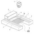
도 1은 제1 실시예에 따라 수행된 작업 트레이를 포함하는 세라믹 재료로 만들어진 그린 피스를 페이스트 공정으로 제조하기 위한 본 발명에 따른 머신의 개략적 사시도로, 도면에서 지지 시트는 생략된다;
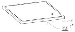
도 2는 도 1의 머신을 구비한 작업 트레이 및 지지 시트의 확대된 분해 사시도이다.
도 3 및 도 4는 도 1 및 도 2의 변형예에 따라 수행된 작업 트레이의 사시도이다.
도 5는 도 1의 머신의 작업 트레이 상에 제조되는 피스의 큰 스케일의 개략적 단면도이며, 상기 단면은 스크레이핑 방향을 따라 만들어진다.
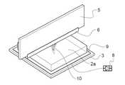
도 6 내지 도 11은 도 1의 머신에 의한 피스의 설치를 도시한다.
도 12 내지 도 14는 적층 가공 기술에 의해 세라믹 재료로 만들어진 그린 피스를 액상 공정에 의해 제조하기 위한 도 1의 머신과 유사한 개략도로서, 도 12의 머신에 대해 위로부터 및 도 13 및 도 14의 머신에 대해 아래로부터 각각 조사하기 위한 수단을 갖는다.
도 15는 지지 시트로 덮인 작업 트레이의 개략적인 단면도이고, 상기 작업 트레이는 선행 도면의 변형예에 따라 만들어진다.
도 16은 지지 시트가 있는 도 15의 트레이의 평면도이고, 지지 시트는 부분적으로 인출된 상태로 도시되어있다.
도 17a 및 도 17b는 본 발명의 제 2 실시예의 제1 변형에 따라 제조된 작동 트레이의 단면도로서, 각 위치들은 상기 트레이에 대해 지지 시트를 붙임 및 분리하기 위한 것이다.
도 18a 및 도 18b는 각각이 제2 실시예의 제2 변형예의 도 17a 및 도 17b에 대응하는 도면이다.1 is a schematic perspective view of a machine according to the invention for producing a green piece made of a ceramic material by a paste process comprising a work tray performed according to a first embodiment, in which the support sheet is omitted;
2 is an enlarged exploded perspective view of a work tray and a support sheet with the machine of FIG. 1;
3 and 4 are perspective views of a work tray performed according to a variant of FIGS. 1 and 2.
5 is a schematic cross-sectional view of a large scale of a piece produced on a work tray of the machine of FIG. 1, the cross section being made along the scraping direction.
6-11 show the installation of the piece by the machine of FIG. 1.
12-14 are schematic views similar to the machine of FIG. 1 for producing, by a liquid phase process, a green piece made of ceramic material by an additive manufacturing technique, from above and with respect to the machine of FIG. Has a means for examining each from below.
15 is a schematic cross-sectional view of a work tray covered with a support sheet, the work tray being made according to a variant of the preceding figures.
FIG. 16 is a plan view of the tray of FIG. 15 with a support sheet, wherein the support sheet is shown in a partially pulled out state. FIG.
17A and 17B are cross-sectional views of an operation tray made in accordance with the first variant of the second embodiment of the present invention, with respective positions for attaching and detaching a support sheet relative to the tray.
18A and 18B are views respectively corresponding to FIGS. 17A and 17B of the second modification of the second embodiment.
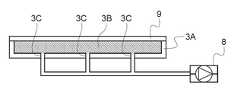
도 1을 참조하면, 적층 가공 기술에 의해 세라믹 재료로 만들어진 성형체(green body)를 제조하기 위한 머신의 작업 트레이(3)의 작업 표면 상의 페이스트 층(2)을 스크레이핑하는 장치(1)가 도시되어 있음을 알 수 있다. 머신의 프레임(4) 상에 활주 가능하게 장착된 스크레이핑 장치(1)는 정면에 수평 스크레이핑 에지를 갖는 스크레이핑 블레이드(6)를 갖춘 갠트리(5)를 포함한다.Referring to FIG. 1, an
작업 트레이(3)는 균일하게 분포된 관통 구멍(3a)의 매트릭스를 갖는다. 도 3 및 도 4에 도시된 변형예에 따르면, 구멍(3a)은 작업 트레이의 에지와 평행한 슬롯(3b)(도 3) 또는 격자 패턴을 형성하도록 배열된 슬롯(3c)(도 4)으로 대체된다.The
도 1에서, 검류기 헤드(galvanometric head)(7)가 또한 도시되어 있으며, 이는 레이저 빔뿐만 아니라 후술하는 기능을 갖는 흡인 시스템(8)을 제어한다.In FIG. 1 a
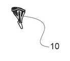
도 5에서, 제조되는 대상물(10) 만이 아니라 지지 시트(9)가 도시되고, 그 기능은 이하 나타낸다.In Fig. 5, not only the
도 1의 머신의 동작은 도 6 내지 도 11을 참조로 설명될 것이다.The operation of the machine of FIG. 1 will be described with reference to FIGS. 6 to 11.
도 6.Figure 6.
제조 초기에, 작업 트레이(3)는 설치 지지체의 역할을 하는 시트(9)를 흡인 및 구속하기 위하여 흡인 시스템(8)을 작동시킴에 의해 오목부(depression) 아래에 놓인다.At the beginning of production, the
도 7.Figure 7.
인쇄된 피스(10)에 대해 고정되고 경질의 기반을 제공하기 위하여 인쇄 전체 기간 동안 흡인 상태가 유지된다.Aspiration is maintained for the entire printing period to provide a rigid and rigid base for the printed
도 8.Figure 8.
인쇄 이후에, 진공 상태가 끝난다.After printing, the vacuum ends.
도 9.Figure 9.
피스(10)를 지지하는 시트(9)는 작업 트레이(3)로부터 용이하게 분리된다.The
도 10.10.
피스(10) 주위의 비경화된 페이스트(2a)가 제거된다. 피스(10)는 여전히 지지 시트(9) 상에 있다.The
도 11.Figure 11.
시트(9)는 피스(10)를 손상을 주지 않고 떼어내기 위하여 변형된다.The
예.Yes.
세라믹 재료의 그린 피스가 도 1의 머신을 이용하여 제조되었다.A green piece of ceramic material was produced using the machine of FIG.
직경 1mm의 서로로부터 7mm 만큼 이격된 구멍(3a)의 매트릭스가 뚫려 있는 작업 트레이(3)가 이용되었다. 두께 100㎛의 폴리염화비닐로 만들어진 시트(9)가 흡인되기 위하여 이 작업 트레이(3) 상에 놓인다; 이를 위하여 베인 펌프(8)를 이용하여 1mbar(100 Pa)의 진공이 생성된다.A
일단 그린 피스(10)가 완성되면, 진공이 풀린다. 피스(10)는 비경화된 페이스트(2a)를 제거하기 위하여 세정된다. 피스(10)는 다음으로 지지 시트(9)로부터 용이하게 분리된다.Once the
도 12 내지 도 14를 참조하면, 액상 공정에 의한 그린 세라믹 피스를 제조하기 위한 머신이 개략적으로 도시되며, 위로부터, 아래로부터, 그리고 아래로부터 각각 조사된다.12 to 14, a machine for producing a green ceramic piece by a liquid phase process is schematically shown and irradiated from above, from below, and from below, respectively.
도 12의 머신은 광경화성 서스펜션이 놓인 통(vat; 11)을 포함한다. 구멍(3'a)이 뚫려 있는 천공 수평 트레이(3')가 조사 수단(7)에 의해 조사될 광경화성 슬러리층에 의해 매번 덮히도록 통(11) 내에 단계적으로 낮춰지도록 장착된다. 본 발명에 따르면, 지지 시트(9)가 트레이(3') 상에 놓이고, 도 1을 참조로 전술한 것처럼 흡인 시스템(8)에 의해 트레이에 대해 흡인된다.The machine of FIG. 12 includes a
도 13의 머신은 조사를 위해 투명한 하부를 갖는 컨테이너(12)를 포함한다.이 컨테이너(12)는 광경화성 슬러리로 채워질 것이다. 구멍(3''a)이 뚫힌 수평 플랫폼(3'')이 콘테이너의 하부에 평행하게 그리고 피스의 경질 설치 지지체를 구성하는 트레이(3'') 상에 형성될 제1 층의 두께에 대응하는 거리만큼 이격되어 콘테이너(12) 내에 위치될 수 있도록 장착되고, 조사는 상기 하부 아래에 위치되는 수단(7)에 의해 수행된다. 본 발명에 따르면, 지지 시트(9)는 상기 트레이(3'') 아래의 흡인 시스템(8)에 의한 흡인에 의해 가압되고, 제1 층의 형성 이후에, 다른 층들 각각을 형성하기 위하여 컨테이너(12) 내에서 단계적으로 상승된다.The machine of FIG. 13 includes a
도 14의 머신은 조사를 위해 투명하고 릴(14)로부터 풀려나와 릴(15)에 감기는 필름(13)을 포함한다. 층이 형성되어야 하는 경우마다, 릴(14 및 15) 사이의 필름(13)의 세그먼트(13a)가 광경화성 슬러리층으로 덮히고, 도 13의 트레이(3'')/지지 시트(9) 어셈블리와 동일한 유형의 트레이(3''')/지지 시트(9) 어셈블리가 붙여지는 슬러리 층과 접촉하도록 낮춰지고, 아래로부터 투명 필름을 통과하는 조사에 의해 경화된다. 트레이(3''')/지지 시트(9) 어셈블리는 다음으로 상승되어, 풀려나온 필름의 다음 세그먼트에 신규 슬러리 층이 붙여지도록 한다. 동작은 소망된 그린 피스가 제공될 때까지 반복된다.The machine of FIG. 14 comprises a
도 15 및 도 16을 참조할 때, 본 발명의 변형예에 따른 작업 트레이가 도시된다. 이 트레이는 하부가 평평하고 예를 들면 금속으로 만들어진 리셉터클(3A)로 구성되며, 리셉터클(3A)의 주위 자유 에지에 따라 할당되는 예를 들면 금속으로 만들어진 그리드(3B)가 내부에 놓인다. 리셉터클(3A)의 하부는 진공 펌프(8)에 연결된 구멍(3C)을 갖는다. 그리드(3B)는 오목부에 분포되도록 하고 리셉터클(3A)은 지지 시트(9)가 그 주위 에지부와 그리드(3B) 상에 가해질 때 강성을 보장하는 프레임을 구성한다.15 and 16, a work tray according to a variant of the present invention is shown. This tray consists of a
그리드(3B)가 리셉터클(3A)의 에지 약간 위에 위치되도록 하는 것이 가능할 것이나, 그리드(3B)가 리셉터클(3A)의 상기 에지로부터 돌출하도록 하는 것은 불가능하다.It would be possible to allow the
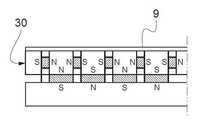
도 17a 및 도 17b를 참조할 때, 기계적으로 작동(도 17a) 및 화살표 f 를 따른 병진 운동에 의해 작동 중지(도 17b) 될 수 있는 영구 자석을 갖는 자기 플랫폼에 의해 구성되는 트레이(30)가 개략적인 단면으로 도시된다. 작동되는 동안, 여기서는 강자성 재료로 만들어진 지지 시트는 트레이(30)의 상부면 상에 견고하게 붙여지고, 작동 중지 동안 지지 시트(9)는 트레이(30)로부터 분리된다. 이 기술은 브레일론에 의해 구현된다(http://www.braillon.com/francais/nostechnologies.html).Referring to FIGS. 17A and 17B, there is a
도 18a 및 도 18b를 참조할 때, 지지 시트(9)가 붙여지는 코일(31)을 갖는 플랫폼(30')이 개략적인 단면으로 도시된다. 이 기술은 또한 브레일론사에서 구현된다.18A and 18B, the
코일(31)을 직류로 여기함에 의해 자계가 생성되며, 지지 시트(9)는 유지된다(도 18a). 코일(31)로 전류가 통과하지 않는 경우, 지지 시트(9)가 분리된다.By exciting the
Claims (25)
Translated fromKorean- 상기 제1 층을 제조하기 이전에
- 상기 작업 트레이(3; 3'; 3"; 3'''; 3A-3B; 30; 30')는 작업 트레이에 대해 바이어스될 수 있는 지지 시트(9)로 덮히고, 연속 층들을 수용하기 위한 경질의 고정 표면을 형성하며, 연속 층들을 형성된 대로 상부에 유지할 수 있으며; 또한
- 상기 지지 시트(9)는 상기 작업 트레이(3; 3'; 3"; 3'''; 3A-3B; 30; 30')에 대해 바이어스되고;
- 상기 그린 피스(10)는 적층 가공 기술에 의해 형성되며; 또한
- 상기 그린 피스(10)가 이렇게 형성되는 경우, 상기 지지 시트(9)를 상기 트레이(3; 3'; 3"; 3'''; 3A-3B; 30; 30')로부터 분리하기 위하여 바이어스가 억제되고, 상기 그린 피스(10)는 경화되지 않은 상기 광경화성 조성물 부분(2a)과 함께 위치되며;
- 상기 경화되지 않은 광경화성 조성물 부분(2a)이 제거되며; 또한
- 상기 그린 피스(10)가 상기 지지 시트(9)로부터 때내어지며,
페이스트 광경화성 조성물이 이용되어 상기 작업 트레이 상에서 한 층씩 확산되는 경우, 층들이 위로부터 조사되며, 또는
슬러리 광경화성 조성물이 이용되는 경우,
상기 트레이는 위로부터 조사되는 연속 층들을 형성하기 위하여 슬러리 내에서 단계별로 낮춰지거나, 또는
상기 트레이는 조사를 위하여 투명한 하부를 갖는 광경화성 조성물 컨테이너의 하부로부터 층의 두께에 대응하는 거리에 배치되고 각 층 형성시 상승되며, 층들은 매번 아래로부터 조사되거나; 또는
상기 트레이는 각 층 형성시에 신규 세그먼트를 제공하기 위하여 수평으로 펼쳐지는 투명 필름의 세그먼트에 붙여지는 슬러리 층과 각 층 형성시에 접촉하며, 층들은 매번 아래로부터 조사되는 것을 특징으로 하는 그린 피스 제조 방법.A method of manufacturing a green piece 10 made of at least one material selected from a ceramic material and a metal material by an additive manufacturing technique, the method comprising: a photocurable composition comprising the ceramic and metal material in powder state and at least The layers of the organic portion and at least one photoinitiator comprising one photocurable monomer and / or oligomer are allowed to cure continuously by irradiation according to the pattern defined for each layer, and the first layer is formed on the working tray , Each other layer is formed on the preceding layer and then cured:
Prior to manufacturing the first layer
The working trays 3; 3 '; 3 ";3''';3A-3B;30; 30 'are covered with a support sheet 9 which can be biased relative to the working trays and receive continuous layers To form a rigid fixed surface for the purpose and to keep the continuous layers on top as formed;
The support sheet 9 is biased against the work tray 3; 3 '; 3 ";3''';3A-3B;30; 30 ';
The green piece 10 is formed by an additive manufacturing technique; Also
If the green piece 10 is thus formed, a bias to separate the support sheet 9 from the trays 3; 3 '; 3 ";3''';3A-3B;30; 30 ' Is suppressed, and the green piece (10) is positioned with the photocurable composition portion (2a) that is not cured;
The uncured photocurable composition portion 2a is removed; Also
The green piece 10 is withdrawn from the support sheet 9,
When a paste photocurable composition is used to diffuse one layer on the work tray, the layers are irradiated from above, or
When slurry photocurable compositions are used,
The tray is lowered step by step in the slurry to form continuous layers irradiated from above, or
The tray is disposed at a distance corresponding to the thickness of the layer from the bottom of the photocurable composition container having a transparent bottom for irradiation and raised at each layer formation, the layers being irradiated from below each time; or
The tray is in contact with each layer forming with a slurry layer attached to a segment of horizontally unfolded transparent film to provide new segments at each layer formation, the layers being irradiated from below each time. Way.
상기 머신은 연속 층들을 조사하기 위한 조사 수단(7)을 더 포함하며,
상기 머신은 상기 작업 트레이(3; 3'; 3"; 3'''; 3A-3B; 30; 30')에 대해, 상기 제1 층의 형성 이전에, 상기 작업 트레이를 덮도록 된 지지 시트(9)를 바이어스하는 수단(8)을 포함하여, 연속하는 층들을 수용하기 위한 경질의 고정 표면을 형성하여, 연속 층들을 형성된 대로 상부에 유지할 수 있으며, 상기 바이어스하는 수단은 상기 트레이(3; 3'; 3"; 3'''; 3A-3B; 30; 30')로부터 상기 지지 시트(9)를 분리하기 위하여 작동 중지될 수 있으며, 상기 지지 시트 위에서 상기 그린 피스(10)는 경화되지 않은 상기 광경화성 조성물 부분(2a)과 함께 위치되며,
페이스트 광경화성 조성물로 그린 피스를 형성하는 경우, 상기 작업 트레이(3) 상의 지지 시트(9)가 위치되는 곳 위에 연속 층들을 확산하기 위하여 페이스트를 스크레이핑 하기 위한 수단(6)을 포함하며, 상기 조사 수단(7)이 위에 배치되거나; 또는
슬러리 광경화성 조성물로 그린 피스를 형성하는 경우,
상기 슬러리로 채워지는 통(11)을 포함하며, 상기 지지 시트(9)가 위치되는 곳 위에서 작업 트레이(3')가 각 단계에서 조사될 층을 위에 형성하도록 단계별로 낮춰질 수 있으며, 상기 조사 수단(7)이 상기 트레이(3') 위에 배치되거나, 또는
조사를 위하여 투명한 하부를 갖는 컨테이너(12)를 포함하며, 상기 지지 시트(9)가 위치하는 곳 아래에 작업 트레이(3'')가 각 단계에서 하부와 상기 지지 시트(9) 사이에 조사될 층을 형성하도록 단계별로 상승될 수 있으며, 상기 조사 수단(7)은 상기 컨테이너(12)의 상기 하부 아래에 배치되거나, 또는
조사를 위하여 투명한 시트(13)를 수평으로 펼쳐지도록 하고, 매번 광경화성 조성물 층을 수용하는 연속하는 시트 세그먼트(13a)를 형성하는 장치를 포함하며, 상기 지지 시트(9)가 위치되는 곳 아래에 작업 트레이(3''')가 매번 투명한 시트의 세그먼트(13a) 상에 배치되는 조사될 층 상에서 낮춰질 수 있도록 되고, 상기 조사 수단(7)은 상기 투명 시트(13) 아래에 배치되는 것을 특징으로 하는 그린 피스 제조 머신.A machine for producing a green piece made of a material selected from a ceramic material and a metal material by an additive manufacturing technique, the machine comprising: a photocurable composition comprising the ceramic and metal material in a powder state and at least one photocurable monomer And / or the organic portion comprising the oligomer and the layers of the at least one photoinitiator are allowed to be cured continuously by irradiation according to the pattern defined for each layer, the first layer being formed on the working tray, and each other layer It is formed on the preceding layer and then cured:
The machine further comprises irradiation means 7 for irradiating continuous layers,
The machine is adapted to cover the work tray, prior to the formation of the first layer, for the work tray 3; 3 '; 3 ";3'";3A-3B;30; 30 '. Means (8) for biasing (9) to form a rigid fixed surface for receiving successive layers, so that the continuous layers can be kept on top as formed, the means for biasing the tray (3); 3 '; 3 ";3''';3A-3B;30; 30 ') may be deactivated to separate the support sheet 9, wherein the green piece 10 is not cured on the support sheet. Which is not with the photocurable composition portion 2a,
When forming a green piece with a paste photocurable composition, it comprises means 6 for scraping the paste to diffuse continuous layers over where the support sheet 9 on the work tray 3 is located, The irradiating means (7) is arranged above; or
When forming the green piece with the slurry photocurable composition,
A barrel 11 filled with the slurry, on which the support sheet 9 is located, the work tray 3 'can be lowered step by step to form a layer to be irradiated thereon in each step, the irradiation Means 7 is arranged on the tray 3 ', or
A container 12 having a transparent lower part for irradiation, and under which the support sheet 9 is located a work tray 3 '' is to be irradiated between the lower part and the supporting sheet 9 at each step. Can be raised step by step to form a layer, the irradiating means 7 being arranged under the bottom of the container 12, or
A device for spreading the transparent sheet 13 horizontally for irradiation and forming a continuous sheet segment 13a which receives a layer of the photocurable composition each time, below where the support sheet 9 is located The work tray 3 '''' can be lowered on the layer to be irradiated which is placed on the segment 13a of the transparent sheet each time, and the irradiating means 7 is arranged below the transparent sheet 13. Green piece manufacturing machine.
24. The magnetic flux of claim 23 wherein the magnetic flux is actuated when direct current is sent to the coil (s) 31 and the current is applied to the electromagnetic tray 30 'with the coil (s) 31. Green piece manufacturing machine, characterized in that it stops when it does not flow through the coil (s) (31).
Applications Claiming Priority (2)
| Application Number | Priority Date | Filing Date | Title |
|---|---|---|---|
| FR1756694AFR3068910B1 (en) | 2017-07-13 | 2017-07-13 | METHOD AND MACHINE FOR MANUFACTURING FLAT WORKPIECES OF CERAMIC AND / OR METALLIC MATERIAL BY THE TECHNIQUE OF ADDITIVE PROCESSES |
| FR1756694 | 2017-07-13 |
Publications (2)
| Publication Number | Publication Date |
|---|---|
| KR20190008130A KR20190008130A (en) | 2019-01-23 |
| KR102075699B1true KR102075699B1 (en) | 2020-02-10 |
Family
ID=60302205
Family Applications (1)
| Application Number | Title | Priority Date | Filing Date |
|---|---|---|---|
| KR1020180081096AExpired - Fee RelatedKR102075699B1 (en) | 2017-07-13 | 2018-07-12 | Method and machine for manufacturing green pieces made of ceramic and/or metallic material by the technique of additive manufacturing |
Country Status (8)
| Country | Link |
|---|---|
| US (1) | US20190015899A1 (en) |
| EP (1) | EP3427924A1 (en) |
| JP (1) | JP2019031075A (en) |
| KR (1) | KR102075699B1 (en) |
| CN (1) | CN109249513A (en) |
| FR (1) | FR3068910B1 (en) |
| RU (1) | RU2688697C1 (en) |
| UA (1) | UA120671C2 (en) |
Cited By (1)
| Publication number | Priority date | Publication date | Assignee | Title |
|---|---|---|---|---|
| WO2023149657A1 (en)* | 2022-02-07 | 2023-08-10 | (주) 유니젯 | 3d printer and disposable film used therein |
Families Citing this family (18)
| Publication number | Priority date | Publication date | Assignee | Title |
|---|---|---|---|---|
| US10668709B2 (en)* | 2014-08-12 | 2020-06-02 | Carbon, Inc. | Three-dimensional printing using carriers with release mechanisms |
| CN109702853B (en)* | 2019-01-24 | 2020-05-01 | 青岛大学 | A method of 3D printing magnetic ceramics and magnetic ceramics prepared therefrom |
| US11144034B2 (en) | 2019-01-30 | 2021-10-12 | General Electric Company | Additive manufacturing systems and methods of generating CAD models for additively printing on workpieces |
| US11498132B2 (en) | 2019-01-30 | 2022-11-15 | General Electric Company | Additive manufacturing systems and methods of calibrating for additively printing on workpieces |
| US11458681B2 (en) | 2019-01-30 | 2022-10-04 | General Electric Company | Recoating assembly for an additive manufacturing machine |
| US11465245B2 (en)* | 2019-01-30 | 2022-10-11 | General Electric Company | Tooling assembly for magnetically aligning components in an additive manufacturing machine |
| US11426799B2 (en) | 2019-01-30 | 2022-08-30 | General Electric Company | Powder seal assembly for decreasing powder usage in a powder bed additive manufacturing process |
| US11198182B2 (en) | 2019-01-30 | 2021-12-14 | General Electric Company | Additive manufacturing systems and methods of additively printing on workpieces |
| US11173574B2 (en) | 2019-01-30 | 2021-11-16 | General Electric Company | Workpiece-assembly and additive manufacturing systems and methods of additively printing on workpieces |
| US11407035B2 (en) | 2019-01-30 | 2022-08-09 | General Electric Company | Powder seal assembly for decreasing powder usage in a powder bed additive manufacturing process |
| US11285538B2 (en) | 2019-01-30 | 2022-03-29 | General Electric Company | Tooling assembly and method for aligning components for a powder bed additive manufacturing repair process |
| CN109693383A (en)* | 2019-02-19 | 2019-04-30 | 张启友 | The air pressure Modeling Platform of 3D printer |
| US11298884B2 (en) | 2019-06-07 | 2022-04-12 | General Electric Company | Additive manufacturing systems and methods of pretreating and additively printing on workpieces |
| CN110449577B (en)* | 2019-06-27 | 2023-07-25 | 天津中德应用技术大学 | An intelligent manufacturing technology and application production training system |
| FR3098438B1 (en)* | 2019-07-08 | 2021-06-11 | S A S 3Dceram Sinto | PASTE LAYER APPLICATION DEVICE FOR AN APPARATUS FOR MANUFACTURING CERAMIC PARTS BY STEREOLITHOGRAPHY |
| WO2021154268A1 (en)* | 2020-01-30 | 2021-08-05 | Hewlett-Packard Development Company, L.P. | Additive manufacturing tray |
| CN111941586B (en)* | 2020-08-05 | 2025-01-24 | 江苏乾度智造高科技有限公司 | A fully automatic high-precision light-curing 3D printer |
| FR3155735A1 (en)* | 2023-11-23 | 2025-05-30 | S.A.S 3Dceram-Sinto | PROCESS FOR MANUFACTURING RAW PARTS MADE OF CERAMIC AND/OR METALLIC MATERIALS USING ADDITIVE PROCESSES |
Citations (4)
| Publication number | Priority date | Publication date | Assignee | Title |
|---|---|---|---|---|
| US20110240245A1 (en)* | 2009-12-30 | 2011-10-06 | Max Eric Schlienger | Systems and methods for filtering molten metal |
| US20110241947A1 (en)* | 2008-10-30 | 2011-10-06 | Mtt Technologies Limited | Additive manufacturing apparatus and method |
| US20150145174A1 (en)* | 2013-11-22 | 2015-05-28 | Stratasys, Inc. | Magnetic platen assembly for additive manufacturing system |
| US20170100899A1 (en)* | 2011-01-31 | 2017-04-13 | Global Filtration Systems, A Dba Of Gulf Filtration Systems Inc. | Method and apparatus for making three-dimensional objects from multiple solidifiable materials |
Family Cites Families (11)
| Publication number | Priority date | Publication date | Assignee | Title |
|---|---|---|---|---|
| JP2000211031A (en)* | 1999-01-26 | 2000-08-02 | Ntt Data Cmet Kk | Support table for stereolithography |
| IN2015DN01776A (en)* | 2012-09-05 | 2015-05-29 | Aprecia Pharmaceuticals Co | |
| US9733429B2 (en)* | 2014-08-18 | 2017-08-15 | Hrl Laboratories, Llc | Stacked microlattice materials and fabrication processes |
| US9592660B2 (en)* | 2014-12-17 | 2017-03-14 | Arevo Inc. | Heated build platform and system for three dimensional printing methods |
| JP6515557B2 (en)* | 2015-02-04 | 2019-05-22 | セイコーエプソン株式会社 | Member for manufacturing three-dimensional object, apparatus for manufacturing three-dimensional object, method for manufacturing three-dimensional object, and three-dimensional object |
| JP2018515371A (en)* | 2015-05-19 | 2018-06-14 | アディファブ アーペーエス | Layered modeling apparatus having a recoat unit and method using the layered modeling apparatus |
| DE102015213103A1 (en)* | 2015-07-13 | 2017-01-19 | Eos Gmbh Electro Optical Systems | Method and device for producing a three-dimensional object |
| US20170072466A1 (en)* | 2015-09-16 | 2017-03-16 | Applied Materials, Inc. | Selectively openable support platen for additive manufacturing |
| US20200238615A1 (en)* | 2015-09-25 | 2020-07-30 | Addifab Aps | Additive manufacturing device and system, modular build platform and build platform unit |
| KR20180081489A (en)* | 2015-09-25 | 2018-07-16 | 카본, 인크. | Build plate assembly for continuous liquid phase printing with illumination panels and related methods, systems and apparatus |
| CA3024147A1 (en)* | 2016-05-31 | 2017-12-07 | Northwestern University | Method for the fabrication of three-dimensional objects and apparatus for same |
- 2017
- 2017-07-13FRFR1756694Apatent/FR3068910B1/ennot_activeExpired - Fee Related
- 2018
- 2018-06-25EPEP18179438.9Apatent/EP3427924A1/ennot_activeWithdrawn
- 2018-07-11UAUAA201807767Apatent/UA120671C2/enunknown
- 2018-07-12KRKR1020180081096Apatent/KR102075699B1/ennot_activeExpired - Fee Related
- 2018-07-12JPJP2018132566Apatent/JP2019031075A/enactivePending
- 2018-07-12RURU2018125625Apatent/RU2688697C1/ennot_activeIP Right Cessation
- 2018-07-13CNCN201810769628.6Apatent/CN109249513A/enactivePending
- 2018-07-13USUS16/034,907patent/US20190015899A1/ennot_activeAbandoned
Patent Citations (4)
| Publication number | Priority date | Publication date | Assignee | Title |
|---|---|---|---|---|
| US20110241947A1 (en)* | 2008-10-30 | 2011-10-06 | Mtt Technologies Limited | Additive manufacturing apparatus and method |
| US20110240245A1 (en)* | 2009-12-30 | 2011-10-06 | Max Eric Schlienger | Systems and methods for filtering molten metal |
| US20170100899A1 (en)* | 2011-01-31 | 2017-04-13 | Global Filtration Systems, A Dba Of Gulf Filtration Systems Inc. | Method and apparatus for making three-dimensional objects from multiple solidifiable materials |
| US20150145174A1 (en)* | 2013-11-22 | 2015-05-28 | Stratasys, Inc. | Magnetic platen assembly for additive manufacturing system |
Cited By (1)
| Publication number | Priority date | Publication date | Assignee | Title |
|---|---|---|---|---|
| WO2023149657A1 (en)* | 2022-02-07 | 2023-08-10 | (주) 유니젯 | 3d printer and disposable film used therein |
Also Published As
| Publication number | Publication date |
|---|---|
| FR3068910B1 (en) | 2019-08-16 |
| EP3427924A1 (en) | 2019-01-16 |
| FR3068910A1 (en) | 2019-01-18 |
| US20190015899A1 (en) | 2019-01-17 |
| UA120671C2 (en) | 2020-01-10 |
| RU2688697C1 (en) | 2019-05-22 |
| KR20190008130A (en) | 2019-01-23 |
| JP2019031075A (en) | 2019-02-28 |
| CN109249513A (en) | 2019-01-22 |
Similar Documents
| Publication | Publication Date | Title |
|---|---|---|
| KR102075699B1 (en) | Method and machine for manufacturing green pieces made of ceramic and/or metallic material by the technique of additive manufacturing | |
| JP5912657B2 (en) | Resin pasting device | |
| KR102170376B1 (en) | 3D object creation system and method | |
| TW201936366A (en) | Stage mechanism, additive manufacturing device, and additive manufacturing method | |
| FR3070134B1 (en) | METHOD AND MACHINE FOR MANUFACTURING AT LEAST ONE PIECE OF AT LEAST ONE CERAMIC AND / OR METALLIC MATERIAL BY THE TECHNIQUE OF ADDITIVE PROCESSES | |
| JP5456400B2 (en) | Manufacturing apparatus and manufacturing method of three-dimensional shaped object | |
| JP2010058440A (en) | Gluing apparatus | |
| KR102122229B1 (en) | 3D Printer using Photopolymerizing | |
| US11951679B2 (en) | Additive manufacturing system | |
| JP2019072967A (en) | Three-dimensional fabrication apparatus and fabrication method of three-dimensional object | |
| JP2023174905A (en) | Three-dimensional printer for additive manufacturing of members and printing method | |
| CN211054415U (en) | D L P type 3D printer | |
| JPH09168840A (en) | Molding method of sand mold by laminating method | |
| JP2013145784A (en) | Resin adhering method | |
| US20230241835A1 (en) | Composite material reinforced stereolithography methods and systems | |
| CN112172132B (en) | Molding table for photo-curing 3D printing equipment and printing method of equipment | |
| CN114939676A (en) | Method for manufacturing three-dimensional shaped object and method for manufacturing sheet cutting device | |
| CN210336902U (en) | A forming table for light curing 3D printing equipment | |
| US20250170647A1 (en) | Process for manufacturing green pieces made of ceramic and/or metallic material by the technique of additive manufacturing | |
| JP2002097532A (en) | Method for manufacturing composite molded article of metal and ceramics, and apparatus | |
| EP4311658A1 (en) | Systems and methods for additive manufacturing | |
| EP4249216A1 (en) | Systems and methods for additive manufacturing | |
| JP3266080B2 (en) | Parts automatic mounting machine | |
| CN119816410A (en) | Device, system and method for automatic powder removal and extraction of three-dimensional printed parts | |
| JP2014078550A (en) | Resin affixing device |
Legal Events
| Date | Code | Title | Description |
|---|---|---|---|
| PA0109 | Patent application | St.27 status event code:A-0-1-A10-A12-nap-PA0109 | |
| A201 | Request for examination | ||
| P11-X000 | Amendment of application requested | St.27 status event code:A-2-2-P10-P11-nap-X000 | |
| P13-X000 | Application amended | St.27 status event code:A-2-2-P10-P13-nap-X000 | |
| PA0201 | Request for examination | St.27 status event code:A-1-2-D10-D11-exm-PA0201 | |
| PN2301 | Change of applicant | St.27 status event code:A-3-3-R10-R13-asn-PN2301 St.27 status event code:A-3-3-R10-R11-asn-PN2301 | |
| PG1501 | Laying open of application | St.27 status event code:A-1-1-Q10-Q12-nap-PG1501 | |
| D13-X000 | Search requested | St.27 status event code:A-1-2-D10-D13-srh-X000 | |
| D14-X000 | Search report completed | St.27 status event code:A-1-2-D10-D14-srh-X000 | |
| P22-X000 | Classification modified | St.27 status event code:A-2-2-P10-P22-nap-X000 | |
| E902 | Notification of reason for refusal | ||
| PE0902 | Notice of grounds for rejection | St.27 status event code:A-1-2-D10-D21-exm-PE0902 | |
| T11-X000 | Administrative time limit extension requested | St.27 status event code:U-3-3-T10-T11-oth-X000 | |
| E13-X000 | Pre-grant limitation requested | St.27 status event code:A-2-3-E10-E13-lim-X000 | |
| P11-X000 | Amendment of application requested | St.27 status event code:A-2-2-P10-P11-nap-X000 | |
| P13-X000 | Application amended | St.27 status event code:A-2-2-P10-P13-nap-X000 | |
| E701 | Decision to grant or registration of patent right | ||
| PE0701 | Decision of registration | St.27 status event code:A-1-2-D10-D22-exm-PE0701 | |
| GRNT | Written decision to grant | ||
| PR0701 | Registration of establishment | St.27 status event code:A-2-4-F10-F11-exm-PR0701 | |
| PR1002 | Payment of registration fee | St.27 status event code:A-2-2-U10-U11-oth-PR1002 Fee payment year number:1 | |
| PG1601 | Publication of registration | St.27 status event code:A-4-4-Q10-Q13-nap-PG1601 | |
| P22-X000 | Classification modified | St.27 status event code:A-4-4-P10-P22-nap-X000 | |
| P22-X000 | Classification modified | St.27 status event code:A-4-4-P10-P22-nap-X000 | |
| PC1903 | Unpaid annual fee | St.27 status event code:A-4-4-U10-U13-oth-PC1903 Not in force date:20230205 Payment event data comment text:Termination Category : DEFAULT_OF_REGISTRATION_FEE | |
| PC1903 | Unpaid annual fee | St.27 status event code:N-4-6-H10-H13-oth-PC1903 Ip right cessation event data comment text:Termination Category : DEFAULT_OF_REGISTRATION_FEE Not in force date:20230205 | |
| R18-X000 | Changes to party contact information recorded | St.27 status event code:A-5-5-R10-R18-oth-X000 |