KR102072686B1 - Image display device - Google Patents
Image display deviceDownload PDFInfo
- Publication number
- KR102072686B1 KR102072686B1KR1020130064842AKR20130064842AKR102072686B1KR 102072686 B1KR102072686 B1KR 102072686B1KR 1020130064842 AKR1020130064842 AKR 1020130064842AKR 20130064842 AKR20130064842 AKR 20130064842AKR 102072686 B1KR102072686 B1KR 102072686B1
- Authority
- KR
- South Korea
- Prior art keywords
- support plate
- hinge
- plate
- display
- hinge bar
- Prior art date
- Legal status (The legal status is an assumption and is not a legal conclusion. Google has not performed a legal analysis and makes no representation as to the accuracy of the status listed.)
- Active
Links
Images


Classifications
- H—ELECTRICITY
- H04—ELECTRIC COMMUNICATION TECHNIQUE
- H04N—PICTORIAL COMMUNICATION, e.g. TELEVISION
- H04N5/00—Details of television systems
- H04N5/64—Constructional details of receivers, e.g. cabinets or dust covers
- G—PHYSICS
- G06—COMPUTING OR CALCULATING; COUNTING
- G06F—ELECTRIC DIGITAL DATA PROCESSING
- G06F1/00—Details not covered by groups G06F3/00 - G06F13/00 and G06F21/00
- G06F1/16—Constructional details or arrangements
- G06F1/1613—Constructional details or arrangements for portable computers
- G06F1/1633—Constructional details or arrangements of portable computers not specific to the type of enclosures covered by groups G06F1/1615 - G06F1/1626
- G06F1/1637—Details related to the display arrangement, including those related to the mounting of the display in the housing
- G06F1/1652—Details related to the display arrangement, including those related to the mounting of the display in the housing the display being flexible, e.g. mimicking a sheet of paper, or rollable
- G—PHYSICS
- G06—COMPUTING OR CALCULATING; COUNTING
- G06F—ELECTRIC DIGITAL DATA PROCESSING
- G06F1/00—Details not covered by groups G06F3/00 - G06F13/00 and G06F21/00
- G06F1/16—Constructional details or arrangements
- G—PHYSICS
- G06—COMPUTING OR CALCULATING; COUNTING
- G06F—ELECTRIC DIGITAL DATA PROCESSING
- G06F1/00—Details not covered by groups G06F3/00 - G06F13/00 and G06F21/00
- G06F1/16—Constructional details or arrangements
- G06F1/1601—Constructional details related to the housing of computer displays, e.g. of CRT monitors, of flat displays
- G—PHYSICS
- G06—COMPUTING OR CALCULATING; COUNTING
- G06F—ELECTRIC DIGITAL DATA PROCESSING
- G06F1/00—Details not covered by groups G06F3/00 - G06F13/00 and G06F21/00
- G06F1/16—Constructional details or arrangements
- G06F1/1613—Constructional details or arrangements for portable computers
- G06F1/1633—Constructional details or arrangements of portable computers not specific to the type of enclosures covered by groups G06F1/1615 - G06F1/1626
- G06F1/1637—Details related to the display arrangement, including those related to the mounting of the display in the housing
- G—PHYSICS
- G06—COMPUTING OR CALCULATING; COUNTING
- G06F—ELECTRIC DIGITAL DATA PROCESSING
- G06F1/00—Details not covered by groups G06F3/00 - G06F13/00 and G06F21/00
- G06F1/16—Constructional details or arrangements
- G06F1/1613—Constructional details or arrangements for portable computers
- G06F1/1633—Constructional details or arrangements of portable computers not specific to the type of enclosures covered by groups G06F1/1615 - G06F1/1626
- G06F1/1675—Miscellaneous details related to the relative movement between the different enclosures or enclosure parts
- G06F1/1681—Details related solely to hinges
- G—PHYSICS
- G06—COMPUTING OR CALCULATING; COUNTING
- G06F—ELECTRIC DIGITAL DATA PROCESSING
- G06F1/00—Details not covered by groups G06F3/00 - G06F13/00 and G06F21/00
- G06F1/16—Constructional details or arrangements
- G06F1/18—Packaging or power distribution
- G06F1/183—Internal mounting support structures, e.g. for printed circuit boards, internal connecting means
- H—ELECTRICITY
- H05—ELECTRIC TECHNIQUES NOT OTHERWISE PROVIDED FOR
- H05K—PRINTED CIRCUITS; CASINGS OR CONSTRUCTIONAL DETAILS OF ELECTRIC APPARATUS; MANUFACTURE OF ASSEMBLAGES OF ELECTRICAL COMPONENTS
- H05K7/00—Constructional details common to different types of electric apparatus
- H05K7/02—Arrangements of circuit components or wiring on supporting structure
Landscapes
- Engineering & Computer Science (AREA)
- Theoretical Computer Science (AREA)
- Computer Hardware Design (AREA)
- General Engineering & Computer Science (AREA)
- Human Computer Interaction (AREA)
- Physics & Mathematics (AREA)
- General Physics & Mathematics (AREA)
- Power Engineering (AREA)
- Microelectronics & Electronic Packaging (AREA)
- Multimedia (AREA)
- Signal Processing (AREA)
- Devices For Indicating Variable Information By Combining Individual Elements (AREA)
Abstract
Translated fromKoreanDescription
Translated fromKorean본 발명은 전자소자가 장착되는 회로기판의 지지 구조를 구비하는 영상표시기기에 관한 것이다.The present invention relates to an image display device having a supporting structure of a circuit board on which an electronic element is mounted.
영상표시기기는 방송을 수신하여 출력하거나, 영상을 기록 및 재생하는 장치와 오디오를 기록 및 재생하는 장치를 모두 포함한다. 이러한 영상표시기기로는 예를 들어, 텔레비전, 모니터, 프로젝터, 태블릿 등이 포함된다.The image display device includes both a device for receiving and outputting a broadcast, recording and reproducing an image, and a device for recording and reproducing audio. Such image display apparatuses include, for example, televisions, monitors, projectors, tablets, and the like.
영상표시기기는 기능이 다양화됨에 따라, 방송의 출력이나 영상의 재생 기능 외에도, 사진이나 동영상의 촬영, 게임, 방송의 수신 등의 복합적인 기능들을 갖춘 멀티미디어 기기(multimedia player) 형태로 구현되고 있다.As the functions of the video display device are diversified, in addition to the output of the broadcast and the playback of the video, the video display device is implemented in the form of a multimedia player having a complex function such as taking a picture or video, playing a game, and receiving a broadcast. .
이러한 영상표시기기의 기능 지지 및 증대를 위해 하드웨어 또는 소프트웨어의 면에서 새로운 다양한 시도들이 적용되고 있다. 하드웨어적인 부분에 해당하는 시도들에는 영상표시기기의 조립 구조를 단순화하는 구조적인 변화 및 개량이 포함된다.In order to support and increase the function of the image display device, various new attempts have been applied in terms of hardware or software. Attempts at the hardware level include structural changes and improvements that simplify the assembly of video display devices.
상기 구조적인 변화 및 개량의 일 예로서, 전자소자가 장착되는 회로기판의 지지 구조에 대한 다양한 연구 및 제안들이 이루어지고 있다. 특히, 최근에는 플렉서블 디스플레이에 대한 연구가 활발히 진행되고 있는데, 이를 구현하기 위해서는 회로기판이 디스플레이와 함께 휘어지도록 구성되거나 디스플레이의 가변시에도 평평한 상태를 유지하도록 이루어져야 한다. 일반적으로, 회로기판은 리지드한(rigid) 재질로 형성되어 디스플레이와 함께 휘어질 수 없다. 따라서, 디스플레이의 가변시에도 회로기판의 평평한 상태가 유지될 수 있는 구조가 고려될 수 있다.As an example of the structural change and improvement, various studies and proposals have been made on the supporting structure of the circuit board on which the electronic device is mounted. In particular, recently, research on flexible displays has been actively conducted. In order to realize this, the circuit board should be configured to be bent together with the display or to be flat even when the display is variable. In general, the circuit board is formed of a rigid material and cannot be bent together with the display. Therefore, a structure in which the flat state of the circuit board can be maintained even when the display is variable can be considered.
본 발명의 일 목적은 종래와 다른 회로기판의 지지 구조를 구비하는 영상표시기기를 제공하는 데에 있다.An object of the present invention is to provide an image display device having a support structure of a circuit board different from the conventional one.
또한, 본 발명의 다른 일 목적은 플렉서블 디스플레이를 구비하는 영상표시기기에서, 디스플레이의 가변시에도 회로기판의 평평한 상태가 유지될 수 있는 구조를 제공하는 데에 있다.Another object of the present invention is to provide a structure in which a flat state of a circuit board can be maintained even when the display is variable in an image display device having a flexible display.
이와 같은 본 발명의 해결 과제를 달성하기 위하여, 본 발명의 일 실시예에 따르는 영상표시기기는, 영상을 출력하도록 형성되는 디스플레이와, 상기 디스플레이의 배면을 덮어 지지하는 제1 지지 플레이트와, 상기 제1 지지 플레이트의 배면으로부터 이격되게 배치되고 전자소자가 장착되는 제2 지지 플레이트, 및 상기 제1 지지 플레이트의 변형시 상기 제2 지지 플레이트는 평평한 상태를 유지하도록 상기 제1 지지 플레이트와 상기 제2 지지 플레이트를 힌지 연결하는 힌지 유닛을 포함한다.In order to achieve the above object of the present invention, an image display device according to an embodiment of the present invention, a display formed to output an image, a first support plate for covering the back of the display, and the first A second support plate disposed to be spaced apart from a rear surface of the first support plate and to which the electronic device is mounted, and the second support plate and the second support plate to maintain a flat state when the first support plate is deformed. And a hinge unit that hinges the plate.
본 발명과 관련된 일 예에 따르면, 상기 힌지 유닛은 상기 제2 지지 플레이트의 양측에 각각 구비된다.According to an example related to the present invention, the hinge units are provided at both sides of the second support plate, respectively.
본 발명과 관련된 다른 일 예에 따르면, 상기 힌지 유닛은, 상기 제1 지지 플레이트와 연결되는 힌지 바, 및 상기 힌지 바에 힌지 결합되고 상기 제2 지지 플레이트를 지지하는 힌지 플레이트를 포함한다.According to another example related to the present invention, the hinge unit includes a hinge bar connected to the first support plate, and a hinge plate hinged to the hinge bar and supporting the second support plate.
상기 힌지 플레이트가 상기 제1 지지 플레이트의 배면으로부터 이격되게 배치될 수 있도록, 상기 힌지 바는 상기 제1 지지 플레이트의 배면으로부터 돌출되는 제1돌출부에 장착될 수 있다. 또한, 상기 제2 지지 플레이트가 상기 제1 지지 플레이트의 배면으로부터 보다 이격되게 배치될 수 있도록, 상기 제2 지지 플레이트는 상기 힌지 플레이트로부터 돌출되는 제2돌출부에 장착될 수 있다.The hinge bar may be mounted to a first protrusion protruding from the rear surface of the first support plate so that the hinge plate may be spaced apart from the rear surface of the first support plate. In addition, the second support plate may be mounted to a second protrusion protruding from the hinge plate so that the second support plate may be disposed more spaced from the rear surface of the first support plate.
상기 힌지 바는 제1수용부를 구비할 수 있고, 상기 힌지 플레이트는 상기 제1수용부와 동축 상에 배치되는 제2수용부를 구비할 수 있으며, 상기 제1 및 제2수용부에는 핀이 삽입되어 상기 힌지 바와 상기 힌지 플레이트가 상대 회전 가능하게 형성될 수 있다.The hinge bar may include a first accommodating part, the hinge plate may include a second accommodating part coaxially disposed with the first accommodating part, and a pin is inserted into the first and second accommodating part. The hinge bar and the hinge plate may be formed to be relatively rotatable.
상기 힌지 바와 상기 힌지 플레이트는 금속 재질로 형성될 수 있다. 이때, 상기 제1 및 제2수용부는 상기 힌지 바와 상기 힌지 플레이트가 각각 벤딩되어 형성될 수 있다.The hinge bar and the hinge plate may be formed of a metal material. In this case, the first and second accommodating parts may be formed by bending the hinge bar and the hinge plate, respectively.
상기 힌지 바 및 상기 힌지 플레이트는 상기 핀의 축 방향을 따라 연장되게 형성될 수 있으며, 상기 제1 및 제2수용부는 상기 핀의 축 상에서 상기 핀의 단부를 포함하여 복수의 개소에 배치될 수 있다.The hinge bar and the hinge plate may be formed to extend along the axial direction of the pin, and the first and second accommodation parts may be disposed at a plurality of locations including the end of the pin on the axis of the pin. .
상기 힌지 바에 대한 상기 힌지 플레이트의 상대 회전 범위가 제한될 수 있도록, 상기 힌지 플레이트는 일 방향으로의 회전시 상기 힌지 바에 걸림되는 스토퍼를 구비할 수 있다. 상기 스토퍼는 상기 힌지 바의 일부를 덮도록 배치될 수 있다. 또한, 상기 스토퍼와 상기 힌지 바 사이에는 탄성 변형 가능한 재질로 형성되는 탄성부재가 배치될 수 있다. 상기 제2 지지 플레이트는 상기 제1 지지 플레이트의 배면 상에서 상기 스토퍼보다 돌출된 위치에 배치될 수 있다.The hinge plate may include a stopper that is engaged with the hinge bar when the hinge plate rotates in one direction so that the relative rotation range of the hinge plate with respect to the hinge bar may be limited. The stopper may be disposed to cover a portion of the hinge bar. In addition, an elastic member formed of an elastically deformable material may be disposed between the stopper and the hinge bar. The second support plate may be disposed at a position protruding from the stopper on the rear surface of the first support plate.
본 발명과 관련된 또 다른 일 예에 따르면, 상기 제2 지지 플레이트는 상기 디스플레이와 관련된 제어신호를 생성하도록 형성되는 회로기판이 될 수 있다. 상기 제2 지지 플레이트 및 상기 제2 지지 플레이트에 장착되는 전자소자는 상기 디스플레이에 전원을 공급하는 파워 서플라이 유닛을 구성할 수 있다. 또한, 상기 회로기판의 단부에는 커넥터가 구비되어 상대 커넥터와 결합 가능하게 구성되며, 상기 상대 커넥터가 상기 힌지 유닛과의 간섭 없이 상기 커넥터에 용이하게 끼워질 수 있도록 상기 커넥터는 상기 제1 지지 플레이트의 배면 상에서 상기 힌지 유닛보다 돌출된 위치에 배치될 수 있다.According to another example related to the present invention, the second support plate may be a circuit board formed to generate a control signal related to the display. The electronic device mounted on the second support plate and the second support plate may constitute a power supply unit for supplying power to the display. In addition, an end portion of the circuit board is provided with a connector so as to be coupled to the mating connector, and the connector may be easily inserted into the connector without interference with the hinge unit. It may be disposed in a position protruding from the hinge unit on the rear surface.
본 발명과 관련된 또 다른 일 예에 따르면, 상기 제2 지지 플레이트는 복수 개로 구비되어 일렬로 배치되고, 상기 제2 지지 플레이트의 양측에 각각 구비되는 상기 힌지 유닛은 일 방향을 따라 연장되게 형성되어 상기 복수의 제2 지지 플레이트와 각각 연결된다.According to another example related to the present invention, the second supporting plate is provided in plurality and arranged in a row, and the hinge units respectively provided on both sides of the second supporting plate are formed to extend in one direction, It is connected with a plurality of second support plates, respectively.
본 발명과 관련된 또 다른 일 예에 따르면, 상기 영상표시기기는, 상기 제1 지지 플레이트와 상기 제2 지지 플레이트 사이에 구비되고 상기 제2 지지 플레이트의 자중에 의한 처짐을 방지하도록 형성되는 홀딩 유닛을 더 포함한다.According to another example related to the present invention, the image display device includes a holding unit provided between the first support plate and the second support plate and formed to prevent sagging due to the weight of the second support plate. It includes more.
상기 홀딩 유닛은, 상기 제1 지지 플레이트에 지지되고 상기 제2 지지 플레이트의 관통홀을 관통하는 바디, 및 상기 제1 지지 플레이트와 상기 제2 지지 플레이트 사이에서 상기 바디를 감싸도록 설치되며 상기 제2 지지 플레이트를 탄성 가압하도록 형성되는 탄성부재를 포함할 수 있다. 또한, 상기 홀딩 유닛은, 상기 바디에서 반경 방향으로 돌출되어 상기 제2 지지 플레이트의 배면을 덮도록 배치되는 이탈방지부를 더 포함할 수 있다.The holding unit is supported by the first support plate and penetrates the through hole of the second support plate, and is installed to surround the body between the first support plate and the second support plate and the second It may include an elastic member formed to elastically press the support plate. In addition, the holding unit may further include a separation prevention part protruding in the radial direction from the body to cover the rear surface of the second support plate.
본 발명과 관련된 또 다른 일 예에 따르면, 상기 영상표시기기는, 상기 제2 지지 플레이트를 덮도록 배치되고 상기 제1 지지 플레이트의 변형에 따라 함께 변형 가능하게 형성되는 백 커버를 더 포함하며, 상기 백 커버는 상기 변형시 상기 제2 지지 플레이트와 접촉되지 않도록 상기 제2 지지 플레이트의 모서리로부터 소정 간격을 두고 이격되게 배치된다.According to another example related to the present invention, the image display device further includes a back cover disposed to cover the second support plate and deformable together according to the deformation of the first support plate. The back cover is spaced apart from the edge of the second support plate at a predetermined distance so as not to contact the second support plate during the deformation.
본 발명과 관련된 또 다른 일 예에 따르면, 상기 영상표시기기는, 상기 제1 지지 플레이트의 배면으로부터 이격되게 배치되는 제3 지지 플레이트, 및 상기 제1 지지 플레이트의 변형시 상기 제3 지지 플레이트의 평평한 상태가 유지될 수 있도록 상기 제3 지지 플레이트보다 작은 면적을 가지고 상기 제1 지지 플레이트와 상기 제3 지지 플레이트 사이를 연결하는 변형 저감부를 더 포함한다.According to another example related to the present invention, the image display device may include a third support plate disposed to be spaced apart from a rear surface of the first support plate, and a flat surface of the third support plate when the first support plate is deformed. It further comprises a deformation reduction portion for connecting between the first support plate and the third support plate having an area smaller than the third support plate so that the state can be maintained.
아울러, 상기한 과제를 실현하기 위하여 본 발명은, 영상을 출력하도록 형성되는 디스플레이와, 상기 디스플레이의 배면을 덮어 지지하는 지지 플레이트와, 상기 지지 플레이트의 배면에서 돌출되고 서로 이격되게 배치되는 복수의 돌출부와, 상기 복수의 돌출부 각각에 장착되는 복수의 힌지 바와, 상기 복수의 힌지 바 각각에 힌지 결합되는 복수의 힌지 플레이트, 및 상기 복수의 힌지 플레이트에 의하여 지지되고 상기 디스플레이와 관련된 제어신호를 생성하도록 형성되는 회로기판을 포함하며, 상기 회로기판은 상기 지지 플레이트의 변형시 상기 힌지 바가 상기 힌지 플레이트에 대하여 회전됨으로써 평평한 상태를 유지하도록 형성되는 영상표시기기를 제공한다.In addition, in order to realize the above object, the present invention, the display is formed to output an image, a support plate for covering the back of the display, and a plurality of protrusions protruding from the back of the support plate and spaced apart from each other And a plurality of hinge bars mounted to each of the plurality of protrusions, a plurality of hinge plates hinged to each of the plurality of hinge bars, and supported by the plurality of hinge plates to generate control signals related to the display. And a circuit board, wherein the circuit board is configured to maintain the flat state by rotating the hinge bar with respect to the hinge plate when the support plate is deformed.
상기와 같은 구성의 본 발명에 의하면, 제2 지지 플레이트는 제1 지지 플레이트의 변형시에도 힌지 유닛에 의하여 평평한 상태를 유지하도록 이루어지므로, 상기 구조가 플렉서블 디스플레이를 구비하는 영상표시기기에 적용될 경우, 회로기판의 신뢰성 이슈가 해결될 수 있다.According to the present invention having the above-described configuration, since the second support plate is made to maintain a flat state by the hinge unit even when the first support plate is deformed, when the structure is applied to an image display device having a flexible display, The reliability issue of the circuit board can be solved.
또한, 힌지 유닛의 회전 범위를 제한하는 스토퍼, 제2 지지 플레이트의 자중에 의한 처짐을 방지하는 홀딩 유닛 등에 의하여, 신뢰성과 내구성이 확보된 영상표시기기가 제공될 수 있다.In addition, an image display device in which reliability and durability are ensured may be provided by a stopper for limiting the rotation range of the hinge unit, a holding unit for preventing sag due to the weight of the second support plate, and the like.
도 1은 본 발명과 관련된 영상표시기기 및 원격제어장치를 보여주는 블록도.
도 2는 도 1의 디스플레이를 상세하게 보여주는 블록도.
도 3은 본 발명의 일 실시예와 관련된 영상표시기기의 배면도.
도 4a 및 4b는 도 3에 도시된 라인 Ⅳ-Ⅳ를 따라 취한 단면도로서, 제1 지지 플레이트가 변형되지 않은 상태와 변형된 상태를 각각 보인 도면.
도 5는 도 4a에 도시된 힌지 유닛의 구성을 보인 개념도.
도 6은 도 4a에 도시된 힌지 유닛의 구성을 보인 개념도.
도 6은 도 3에 도시된 A 부분을 3차원으로 보인 사시도.
도 7은 힌지 유닛의 변형예들을 보인 개념도.
도 8은 도 4a에 도시된 홀딩 유닛 부분을 확대하여 보인 단면도.
도 9는 본 발명의 다른 일 실시예와 관련된 영상표시기기의 배면도.
도 10은 본 발명의 또 다른 일 실시예와 관련된 영상표시기기의 배면도.
도 11은 도 10에 도시된 라인 XI-XI을 따라 취한 단면도.1 is a block diagram showing a video display device and a remote control device related to the present invention.
FIG. 2 is a block diagram showing the display of FIG. 1 in detail. FIG.
3 is a rear view of an image display device related to an embodiment of the present invention;
4A and 4B are cross-sectional views taken along the line IV-IV shown in FIG. 3, showing a state in which the first support plate is not deformed and a deformed state, respectively.
FIG. 5 is a conceptual diagram showing the configuration of the hinge unit shown in FIG. 4A. FIG.
FIG. 6 is a conceptual view showing the configuration of the hinge unit shown in FIG. 4A. FIG.
FIG. 6 is a perspective view of a portion A shown in FIG. 3 in three dimensions. FIG.
7 is a conceptual view showing modifications of the hinge unit.
FIG. 8 is an enlarged cross-sectional view of the holding unit part shown in FIG. 4A; FIG.
9 is a rear view of an image display device according to another embodiment of the present invention.
10 is a rear view of an image display device according to another embodiment of the present invention;
FIG. 11 is a cross sectional view taken along the line XI-XI shown in FIG. 10; FIG.
이하, 본 발명과 관련된 영상표시기기에 대하여 도면을 참조하여 보다 상세하게 설명한다.Hereinafter, an image display device according to the present invention will be described in detail with reference to the accompanying drawings.
본 명세서에서는 서로 다른 실시예라도 동일·유사한 구성에 대해서는 동일·유사한 참조번호를 부여하고, 그 설명은 처음 설명으로 갈음한다.In the present specification, the same or similar reference numerals are assigned to the same or similar configurations in different embodiments, and the description thereof is replaced with the first description.
이하의 설명에서 사용되는 구성요소에 대한 접미사 "모듈" 및 "부"는 단순히 본 명세서 작성의 용이함만이 고려되어 부여되는 것으로서, 그 자체로 특별히 중요한 의미 또는 역할을 부여하는 것은 아니다. 따라서, 상기 "모듈" 및 "부"는 서로 혼용되어 사용될 수도 있다.The suffixes "module" and "unit" for components used in the following description are merely given in consideration of ease of preparation of the present specification, and do not impart any particular meaning or role by themselves. Therefore, the "module" and "unit" may be used interchangeably.
또한, 본 명세서에서 사용되는 단수의 표현은 문맥상 명백하게 다르게 뜻하지 않는 한 복수의 표현을 포함한다.Also, the singular forms used herein include the plural forms unless the context clearly indicates otherwise.
본 발명과 관련된 영상표시기기는 방송을 수신하여 출력하거나, 영상을 기록 및 재생하는 장치와 오디오를 기록 및 재생하는 장치를 모두 포함한다. 이하, 이러한 예로서, 텔레비전을 예를 들어 설명한다.The image display device related to the present invention includes both an apparatus for receiving and outputting a broadcast, recording and reproducing an image, and an apparatus for recording and reproducing audio. Hereinafter, the television will be described by way of example.
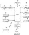
도 1은 본 발명과 관련된 영상표시기기(100) 및 원격제어장치(10)를 보여주는 블록도이다.1 is a block diagram illustrating an
도 1을 참조하면, 영상표시기기(100)는 튜너(110), 복조부(120), 외부장치 인터페이스부(130), 네트워크 인터페이스부(135), 저장부(140), 사용자입력 인터페이스부(150), 제어부(170), 디스플레이(180), 디스플레이 변형 구동부(183), 오디오 출력부(185), 전원공급부(190) 및 3D 시청장치(195)를 포함할 수 있다.Referring to FIG. 1, the
튜너(110)는 안테나를 통해 수신되는 RF(Radio Frequency) 방송 신호 중 사용자에 의해 선택된 채널 또는 기저장된 모든 채널에 해당하는 RF 방송 신호를 선택한다. 또한, 선택된 RF 방송 신호를 중간 주파수 신호 혹은 베이스 밴드 영상 또는 음성신호로 변환한다.The
예를 들어, 선택된 RF 방송 신호가 디지털 방송 신호이면 디지털 IF 신호(DIF)로 변환하고, 아날로그 방송 신호이면 아날로그 베이스 밴드 영상 또는 음성 신호(CVBS/SIF)로 변환한다. 즉, 튜너(110)는 디지털 방송 신호 또는 아날로그 방송 신호를 처리할 수 있다. 튜너(110)에서 출력되는 아날로그 베이스 밴드 영상 또는 음성 신호(CVBS/SIF)는 제어부(170)로 직접 입력될 수 있다.For example, if the selected RF broadcast signal is a digital broadcast signal, it is converted into a digital IF signal (DIF). If the analog broadcast signal is converted into an analog baseband video or audio signal (CVBS / SIF). That is, the
또한, 튜너(110)는 ATSC(Advanced Television System Committee) 방식에 따른 단일 캐리어의 RF 방송 신호 또는 DVB(Digital Video Broadcasting) 방식에 따른 복수 캐리어의 RF 방송 신호를 수신할 수 있다.In addition, the
한편, 튜너(110)는 본 발명에서 안테나를 통해 수신되는 RF 방송 신호 중 채널 기억 기능을 통하여 저장된 모든 방송 채널의 RF 방송 신호를 순차적으로 선택하여 이를 중간 주파수 신호 혹은 베이스 밴드 영상 또는 음성 신호로 변환할 수 있다.Meanwhile, the
복조부(120)는 튜너(110)에서 변환된 디지털 IF 신호(DIF)를 수신하여 복조 동작을 수행한다.The
예를 들어, 튜너(110)에서 출력되는 디지털 IF 신호가 ATSC 방식인 경우, 복조부(120)는 8-VSB(8-Vestigal Side Band) 복조를 수행한다. 또한, 복조부(120)는 채널 복호화를 수행할 수도 있다. 이를 위해 복조부(120)는 트렐리스 디코더(Trellis Decoder), 디인터리버(De-interleaver) 및 리드 솔로먼 디코더(Reed Solomon Decoder) 등을 구비하여, 트렐리스 복호화, 디인터리빙 및 리드 솔로먼 복호화를 수행할 수 있다.For example, when the digital IF signal output from the
예를 들어, 튜너(110)에서 출력되는 디지털 IF 신호가 DVB 방식인 경우, 복조부(120)는 COFDMA(Coded Orthogonal Frequency Division Modulation) 복조를 수행한다. 또한, 복조부(120)는 채널 복호화를 수행할 수도 있다. 이를 위해, 복조부(120)는 컨벌루션 디코더(convolution decoder), 디인터리버 및 리드-솔로먼 디코더 등을 구비하여, 컨벌루션 복호화, 디인터리빙 및 리드 솔로먼 복호화를 수행할 수 있다.For example, when the digital IF signal output from the
복조부(120)는 복조 및 채널 복호화를 수행한 후 스트림 신호(TS)를 출력할 수 있다. 이때 스트림 신호는 영상 신호, 음성 신호 또는 데이터 신호가 다중화된 신호일 수 있다. 일예로, 스트림 신호는 MPEG-2 규격의 영상 신호, 돌비(Dolby) AC-3 규격의 음성 신호 등이 다중화된 MPEG-2 TS(Transport Stream)일수 있다. 구체적으로 MPEG-2 TS는 4 바이트(byte)의 헤더와 184 바이트의 페이로드(payload)를 포함할 수 있다.The
한편, 상술한 복조부(120)는 ATSC 방식과 DVB 방식에 따라 각각 별개로 구비되는 것이 가능하다. 즉, ATSC 복조부와 DVB 복조부로 구비되는 것이 가능하다.On the other hand, the
복조부(120)에서 출력한 스트림 신호는 제어부(170)로 입력될 수 있다. 제어부(170)는 역다중화, 영상/음성 신호 처리 등을 수행한 후, 디스플레이(180)에 영상을 출력하고, 오디오 출력부(185)로 음성을 출력한다.The stream signal output from the
외부장치 인터페이스부(130)는 외부 장치와 영상표시기기(100)를 접속할 수 있다. 이를 위해, 외부장치 인터페이스부(130)는 A/V 입출력부(미도시) 또는 무선 통신부(미도시)를 포함할 수 있다.The external
외부장치 인터페이스부(130)는 DVD(Digital Versatile Disk), 블루레이(Blu ray), 게임기기, 카메라, 캠코더, 컴퓨터(노트북) 등과 같은 외부 장치와 유/무선으로 접속될 수 있다. 외부장치 인터페이스부(130)는 연결된 외부 장치를 통하여 외부에서 입력되는 영상, 음성 또는 데이터 신호를 영상표시기기(100)의 제어부(170)로 전달한다. 또한, 제어부(170)에서 처리된 영상, 음성 또는 데이터 신호를 연결된 외부 장치로 출력할 수 있다. 이를 위해, 외부장치 인터페이스부(130)는 A/V 입출력부(미도시) 또는 무선 통신부(미도시)를 포함할 수 있다.The external
A/V 입출력부는 외부 장치의 영상 및 음성 신호를 영상표시기기(100)로 입력할 수 있도록, USB 단자, CVBS(Composite Video Banking Sync) 단자, 컴포넌트 단자, S-비디오 단자(아날로그), DVI(Digital Visual Interface) 단자, HDMI(High Definition Multimedia Interface) 단자, RGB 단자, D-SUB 단자 등을 포함할 수 있다.The A / V input / output unit can be used to input video and audio signals from an external device to the
무선 통신부는 다른 전자기기와 근거리 무선 통신을 수행할 수 있다. 영상표시기기(100)는 블루투스(Bluetooth), RFID(Radio Frequency Identification), 적외선 통신(IrDA, infrared Data Association), UWB(Ultra Wideband), 지그비(ZigBee) 등의 통신 규격에 따라 다른 전자기기와 네트워크 연결될 수 있다.The wireless communication unit may perform near field communication with other electronic devices. The
또한, 외부장치 인터페이스부(130)는 다양한 셋탑 박스와 상술한 각종 단자 중 적어도 하나를 통해 접속되어, 셋탑 박스와 입력/출력 동작을 수행할 수도 있다.In addition, the external
한편, 외부장치 인터페이스부(130)는 3D 시청장치(195)와 데이터를 송수신할 수 있다.The external
네트워크 인터페이스부(135)는 영상표시기기(100)를 인터넷망을 포함하는 유/무선 네트워크와 연결하기 위한 인터페이스를 제공한다. 네트워크 인터페이스부(135)는 유선 네트워크와의 접속을 위해, 이더넷(Ethernet) 단자 등을 구비할 수 있으며, 무선 네트워크와의 접속을 위해, WLAN(Wireless LAN)(Wi-Fi), Wibro(Wireless broadband), Wimax(World Interoperability for Microwave Access), HSDPA(High Speed Downlink Packet Access) 통신 규격 등이 이용될 수 있다.The
네트워크 인터페이스부(135)는 네트워크를 통해, 인터넷 또는 컨텐츠 제공자 또는 네트워크 운영자가 제공하는 컨텐츠 또는 데이터들을 수신할 수 있다. 즉, 네트워크를 통하여 컨텐츠 제공자로부터 제공되는 영화, 광고, 게임, VOD, 방송 신호 등의 컨텐츠 및 그와 관련된 정보를 수신할 수 있다. 또한, 네트워크 운영자가 제공하는 펌웨어의 업데이트 정보 및 업데이트 파일을 수신할 수 있다. 또한, 인터넷 또는 컨텐츠 제공자 또는 네트워크 운영자에게 데이터들을 송신할 수 있다.The
또한, 네트워크 인터페이스부(135)는 예를 들어, IP(internet Protocol) TV와 접속되어, 양방향 통신이 가능하도록, IPTV용 셋탑 박스에서 처리된 영상, 음성 또는 데이터 신호를 수신하여 제어부(170)로 전달할 수 있으며, 제어부(170)에서 처리된 신호들을 IPTV용 셋탑 박스로 전달할 수 있다.In addition, the
한편, 상술한 IPTV는 전송네트워크의 종류에 따라 ADSL-TV, VDSL-TV, FTTH-TV 등을 포함하는 의미일 수 있으며, TV over DSL, Video over DSL, TV overIP(TVIP), Broadband TV(BTV) 등을 포함하는 의미일 수 있다. 또한, IPTV는 인터넷 접속이 가능한 인터넷 TV, 풀브라우징 TV를 포함하는 의미일 수도 있다.Meanwhile, the above-described IPTV may mean ADSL-TV, VDSL-TV, FTTH-TV, etc. according to the type of transmission network, and include TV over DSL, Video over DSL, TV overIP (TVIP), and Broadband TV (BTV). ) And the like. In addition, IPTV may also mean including an Internet TV with Internet access and a full browsing TV.
저장부(140)는 제어부(170) 내의 각 신호 처리 및 제어를 위한 프로그램이 저장될 수도 있고, 신호 처리된 영상, 음성 또는 데이터 신호를 저장할 수도 있다.The
또한, 저장부(140)는 외부장치 인터페이스부(130)로 입력되는 영상, 음성 또는 데이터 신호의 임시 저장을 위한 기능을 수행할 수도 있다. 또한, 저장부(140)는 채널 맵 등의 채널 기억 기능을 통하여 소정 방송 채널에 관한 정보를 저장할 수 있다.In addition, the
저장부(140)는 플래시 메모리 타입(flash memory type), 하드디스크 타입(hard disk type), 멀티미디어 카드 마이크로 타입(multimedia card micro type), 카드 타입의 메모리(예를 들어 SD 또는 XD 메모리 등), 램, 롬(EEPROM 등) 중 적어도 하나의 타입의 저장매체를 포함할 수 있다. 영상표시기기(100)는 저장부(140) 내에 저장되어 있는 파일(동영상 파일, 정지영상 파일, 음악 파일, 문서 파일 등)을 재생하여 사용자에게 제공할 수 있다.The
도 1은 저장부(140)가 제어부(170)와 별도로 구비된 실시예를 도시하고 있으나, 본 발명의 범위는 이에 한정되지 않는다. 저장부(140)는 제어부(170) 내에 포함될 수 있다.1 illustrates an embodiment in which the
사용자입력 인터페이스부(150)는 사용자가 입력한 신호를 제어부(170)로 전달하거나, 제어부(170)로부터의 신호를 사용자에게 전달한다.The user
예를 들어, 사용자입력 인터페이스부(150)는 RF(Radio Frequency) 통신 방식, 적외선(IR) 통신 방식 등 다양한 통신 방식에 따라, 원격제어장치(10)로부터 전원 온/오프, 채널 선택, 화면 설정 등의 사용자 입력 신호를 수신하거나, 제어부(170)로부터의 신호를 원격제어장치(10)로 송신할 수 있다.For example, the user
또한, 예를 들어, 사용자입력 인터페이스부(150)는 전원키, 채널키, 볼륨키, 설정치 등의 로컬키(미도시)에서 입력되는 사용자 입력 신호를 제어부(170)에 전달할 수 있다.In addition, for example, the user
또한, 예를 들어, 사용자입력 인터페이스부(150)는 사용자의 제스처를 센싱하는 센싱부(미도시)로부터 입력되는 사용자 입력 신호를 제어부(170)에 전달하거나, 제어부(170)로부터의 신호를 센싱부(미도시)로 송신할 수 있다. 여기서, 센싱부(미도시)는 터치 센서, 음성 센서, 위치 센서, 동작 센서 등을 포함할 수 있다.Also, for example, the user
제어부(170)는 튜너(110) 또는 복조부(120) 또는 외부장치 인터페이스부(130)를 통하여, 입력되는 스트림을 역다중화하거나, 역다중화된 신호들을 처리하여, 영상 또는 음성 출력을 위한 신호를 생성 및 출력할 수 있다.The
제어부(170)에서 영상 처리된 영상 신호는 디스플레이(180)로 입력되어, 해당 영상 신호에 대응하는 영상으로 표시될 수 있다. 또한, 제어부(170)에서 영상 처리된 영상 신호는 외부장치 인터페이스부(130)를 통하여 외부 출력장치로 입력될 수 있다.The image signal processed by the
제어부(170)에서 처리된 음성 신호는 오디오 출력부(185)로 음향 출력될 수 있다. 또한, 제어부(170)에서 처리된 음성 신호는 외부장치 인터페이스부(130)를 통하여 외부 출력장치로 입력될 수 있다. 도 1에는 도시되어 있지 않으나, 제어부(170)는 역다중화부, 영상처리부 등을 포함할 수 있다.The voice signal processed by the
그 외, 제어부(170)는 영상표시기기(100) 내의 전반적인 동작을 제어할 수 있다. 예를 들어, 제어부(170)는 튜너(110)를 제어하여, 사용자가 선택한 채널 또는 기저장된 채널에 해당하는 RF 방송을 선택(Tuning)하도록 제어할 수 있다.In addition, the
또한, 제어부(170)는 사용자입력 인터페이스부(150)를 통하여 입력된 사용자 명령 또는 내부 프로그램에 의하여 영상표시기기(100)를 제어할 수 있다.In addition, the
예를 들어, 제어부(170)는 사용자입력 인터페이스부(150)를 통하여 수신한 소정 채널 선택 명령에 따라 선택한 채널의 신호가 입력되도록 튜너(110)를 제어한다. 그리고, 선택한 채널의 영상, 음성 또는 데이터 신호를 처리한다. 제어부(170)는 사용자가 선택한 채널 정보 등이 처리한 영상 또는 음성신호와 함께 디스플레이(180) 또는 오디오 출력부(185)를 통하여 출력될 수 있도록 한다.For example, the
다른 예로, 제어부(170)는 사용자입력 인터페이스부(150)를 통하여 수신한 외부장치 영상 재생 명령에 따라, 외부장치 인터페이스부(130)를 통하여 입력되는 외부 장치, 예를 들어, 카메라 또는 캠코더로부터의 영상 신호 또는 음성 신호가 디스플레이(180) 또는 오디오 출력부(185)를 통해 출력될 수 있도록 한다.As another example, the
한편, 제어부(170)는 영상을 표시하도록 디스플레이(180)를 제어할 수 있다. 예를 들어, 튜너(110)를 통해 입력되는 방송 영상, 외부장치 인터페이스부(130)를 통해 입력되는 외부 입력 영상 또는 네트워크 인터페이스부(135)를 통해 입력되는 영상 또는 저장부(140)에 저장된 영상을 디스플레이(180)에 표시하도록 제어할 수 있다.The
이때, 디스플레이(180)에 표시되는 영상은, 정지 영상 또는 동영상일 수 있으며, 2D 영상 또는 3D 영상일 수 있다.In this case, the image displayed on the
한편, 제어부(170)는 디스플레이(180)에 표시되는 영상 중에, 소정 오브젝트에 대해 3D 오브젝트로 생성하여 표시되도록 한다. 예를 들어, 오브젝트는 접속된 웹 화면(신문, 잡지 등), EPG(Electronic Program Guide), 다양한 메뉴, 위젯, 아이콘, 정지 영상, 동영상, 텍스트 중 적어도 하나일 수 있다.Meanwhile, the
이러한 3D 오브젝트는 디스플레이(180)에 표시되는 영상과 다른 깊이를 가지도록 처리될 수 있다. 바람직하게는 3D 오브젝트가 디스플레이(180)에 표시되는 영상에 비해 돌출되어 보이도록 처리될 수 있다.Such a 3D object may be processed to have a depth different from that of the image displayed on the
한편, 제어부(170)는 촬영부(미도시)로부터 촬영된 영상에 기초하여, 사용자의 위치를 인식한다. 예를 들어, 사용자와 영상표시기기(100) 간의 거리(z축 좌표)를 파악할 수 있다. 그 외, 사용자 위치에 대응하는 영상표시기기(100) 내의 x축 좌표 및 y축 좌표를 파악할 수 있다.The
한편, 도면에 도시하지 않았지만, 채널 신호 또는 외부 입력 신호에 대응하는 썸네일 영상을 생성하는 채널 브라우징 처리부가 더 구비되는 것도 가능하다. 채널 브라우징 처리부는 복조부(120)에서 출력한 스트림 신호(TS) 또는 외부장치 인터페이스부(130)에서 출력한 스트림 신호 등을 입력받아, 입력되는 스트림 신호로부터 영상을 추출하여 썸네일 영상을 생성할 수 있다. 생성된 썸네일 영상은 그대로 또는 부호화되어 제어부(170)로 입력될 수 있다. 또한, 생성된 썸네일 영상은 스트림 형태로 부호화되어 제어부(170)로 입력되는 것도 가능하다. 제어부(170)는 입력된 썸네일 영상을 이용하여 복수의 썸네일 영상을 구비하는 썸네일 리스트를 디스플레이(180)에 표시할 수 있다. 이때의 썸네일 리스트는 디스플레이(180)에 소정 영상을 표시한 상태에서 일부 영역에 표시되는 간편 보기 방식으로 표시되거나, 디스플레이(180)의 대부분 영역에 표시되는 전체 보기 방식으로 표시될 수 있다.Although not shown in the drawing, a channel browsing processor may be further provided to generate a thumbnail image corresponding to the channel signal or the external input signal. The channel browsing processor may receive a stream signal TS output from the
디스플레이(180)는 제어부(170)에서 처리된 영상 신호, 데이터 신호, OSD 신호, 제어 신호 또는 외부장치 인터페이스부(130)에서 수신되는 영상 신호, 데이터 신호, 제어 신호 등을 변환하여 구동 신호를 생성한다.The
본 발명에서는 디스플레이(180)가 평평한(flat) 형태 또는 곡선(curved) 형태로 변형 가능한 플렉서블 디스플레이로 구성되는 것을 예시하고 있다. 디스플레이(180)가 전면 상의 사용자를 감싸듯 곡선 형태로 변형되는 경우, 사용자에게 실감나는 화질과 몰입감이 제공될 수 있다. 이러한 플렉서블 디스플레이는 예를 들어, OLED 패널에 의하여 구현될 수 있다.In the present invention, the
디스플레이(180)는 사용자에게 3차원 영상을 제공하도록 구성될 수 있다. 3차원 영상 시청을 위해 디스플레이(180)는 추가 디스플레이 방식과 단독 디스플레이 방식으로 나뉠 수 있다.The
단독 디스플레이 방식은, 별도의 3D 시청장치(195), 예를 들어 3D 안경 등이 없이, 디스플레이(180) 단독으로 3D 영상을 구현할 수 있는 것으로서, 그 예로, 렌티큘라 방식, 파라랙스 베리어(parallax barrier) 등 다양한 방식이 적용될 수 있다.The independent display method may implement a 3D image by the
한편, 추가 디스플레이 방식은, 디스플레이(180) 외에 3D 시청장치(195)를 사용하여 3D 영상을 구현할 수 있는 것으로서, 그 예로, 헤드 마운트 디스플레이(HMD) 타입, 안경 타입 등 다양한 방식이 적용될 수 있다. 또한, 안경 타입은, 편광 안경 타입 등의 패시브(passive) 방식과, 셔터 글래스(Shutter Glass) 타입 등의 액티브(active) 방식으로 다시 나뉠 수 있다. 한편, 헤드 마운트 디스플레이 타입에서도 패시브 방식과 액티브 방식으로 나뉠 수 있다.Meanwhile, the additional display method may implement a 3D image using the
한편, 디스플레이(180)는 터치 스크린으로 구성되어 출력 장치 이외에 입력 장치로 사용되는 것도 가능하다.Meanwhile, the
디스플레이 변형 구동부(183)는 디스플레이(180)를 평평한 형태 또는 곡선 형태로 변형시키도록 형성된다. 디스플레이 변형 구동부(183)는 디스플레이(180)에 전기적 신호를 주어 디스플레이(180)가 스스로 변형 가능하도록 형성되거나, 디스플레이(180)에 직접 또는 간접적으로 물리적 힘을 가하여 디스플레이(180)가 변형되도록 구성될 수 있다.The
오디오 출력부(185)는 제어부(170)에서 음성 처리된 신호, 예를 들어, 스테레오 신호, 3.1 채널 신호 또는 5.1 채널 신호를 입력 받아 음성으로 출력한다. 오디오 출력부(185)는 다양한 형태의 스피커로 구현될 수 있다.The
한편, 사용자의 제스처를 감지하기 위해, 상술한 바와 같이, 터치 센서, 음성 센서, 위치 센서, 동작 센서 중 적어도 하나를 구비하는 센싱부(미도시)가 영상표시기기(100)에 더 구비될 수 있다. 센싱부(미도시)에서 감지된 신호는 사용자입력 인터페이스부(150)를 통해 제어부(170)로 전달된다.Meanwhile, in order to detect a gesture of a user, as described above, a sensing unit (not shown) including at least one of a touch sensor, a voice sensor, a position sensor, and a motion sensor may be further provided in the
제어부(170)는 촬영부(미도시)로부터 촬영된 영상, 또는 센싱부(미도시)로부터의 감지된 신호를 각각 또는 조합하여 사용자의 제스처를 감지할 수 있다.The
전원 공급부(190)는 영상표시기기(100) 전반에 걸쳐 해당 전원을 공급한다. 특히, 시스템 온 칩(System On Chip,SOC)의 형태로 구현될 수 있는 제어부(170)와, 영상 표시를 위한 디스플레이(180) 및 오디오 출력을 위한 오디오 출력부(185)에 전원을 공급할 수 있다. 또한, 실시예에 따라서는 열선을 포함하는 발열부로 전원을 공급할 수 있다.The
원격제어장치(10)는 사용자 입력을 사용자입력 인터페이스부(150)로 송신한다. 이를 위해, 원격제어장치(10)는 적외선(IR) 통신, RF(Radio Frequency) 통신, 블루투스(Bluetooth), UWB(Ultra Wideband), 지그비(ZigBee) 방식 등을 사용할 수 있다. 또한, 원격제어장치(10)는 사용자입력 인터페이스부(150)에서 출력한 영상, 음성 또는 데이터 신호 등을 수신하여, 이를 원격제어장치(10)에서 표시하거나 음성 출력할 수 있다.The remote controller 10 transmits the user input to the user
상술한 영상표시기기(100)는 고정형으로서 ATSC 방식(8-VSB 방식)의 디지털 방송, DVB-T 방식(COFDM 방식)의 디지털 방송, ISDB-T 방식(BST-OFDM방식)의 디지털 방송 등 중 적어도 하나를 수신 가능한 디지털 방송 수신기일 수 있다. 또한, 이동형으로서 지상파 DMB 방식의 디지털 방송, 위성 DMB 방식의 디지털 방송, ATSC-M/H 방식의 디지털 방송, DVB-H 방식(COFDM 방식)의 디지털 방송, 미디어플로(Media Foward Link Only) 방식의 디지털 방송 등 중 적어도 하나를 수신 가능한 디지털 방송 수신기일 수 있다. 또한, 케이블, 위성통신, IPTV 용 디지털 방송 수신기일 수도 있다.The above-described
한편, 본 명세서에서 기술되는 영상표시기기는 TV 수상기, 휴대폰, 스마트 폰(smart phone), 노트북 컴퓨터(notebook computer), 디지털 방송용 단말기, PDA(Personal Digital Assistants), PMP(Portable Multimedia Player) 등이 포함될 수 있다.On the other hand, the video display device described herein includes a TV receiver, a mobile phone, a smart phone (notebook computer), a notebook computer (digital broadcasting terminal), PDA (Personal Digital Assistants), PMP (Portable Multimedia Player), etc. Can be.
한편, 도 1에 도시된 영상표시기기(100)의 블록도는 본 발명의 일 실시예를 위한 블록도이다. 블록도의 각 구성요소는 실제 구현되는 영상표시기기(100)의 사양에 따라 통합, 추가, 또는 생략될 수 있다. 즉, 필요에 따라 2 이상의 구성요소가 하나의 구성요소로 합쳐지거나, 혹은 하나의 구성요소가 2 이상의 구성요소로 세분되어 구성될 수 있다. 또한, 각 블록에서 수행하는 기능은 본 발명의 실시예를 설명하기 위한 것이며, 그 구체적인 동작이나 장치는 본 발명의 권리범위를 제한하지 아니한다.Meanwhile, a block diagram of the
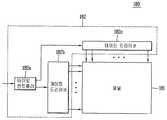
도 2는 도 1의 디스플레이(180)를 상세하게 보여주는 블록도이다.2 is a block diagram illustrating in detail the
도 2를 참조하면, 디스플레이(180)는 유기발광다이오드(OLED) 패널[이하, 패널(181)] 및 구동회로부(182)를 포함하는 디스플레이 모듈일 수 있다.Referring to FIG. 2, the
패널(181)은, 전자를 제공하는 음극(cathode) 상에 전자를 유기물질로 운반시키는 전자 수송층(electron transport layer)이 배치되고, 정공을 제공하는 양극(anode) 아래에 정공을 유기물질로 운반시키는 정공 수송층(hole transport layer)이 배치되며, 전자 수송층과 정공 수송층 사이에 전자와 정공이 결합하여 빛을 낼 수 있는 유기 발광층(emission layer)이 구비되는 구조를 가질 수 있다.The
구동 회로부(182)는 도 1의 제어부(170)로부터 공급되는 제어신호를 통해 패널(181)을 구동한다. 이를 위해, 구동 회로부(182)는 타이밍 컨트롤러(182a), 게이트 드라이버(182b), 데이터 드라이버(182c)를 포함한다.The driving
타이밍 컨트롤러(182a)는 제어부(170)로부터의 제어 신호 및 RGB 데이터 신호, 수직동기신호(Vsync) 등을 입력받아, 제어 신호에 대응하여 게이트 드라이버(182b)와 데이터 드라이버(182c)를 제어하고, RGB 데이터 신호를 재배치하여, 데이터 드라이브(182c)에 제공한다.The
게이트 드라이버(182b)와 데이터 드라이버(182c)는, 타이밍 컨트롤러(182a)의 제어에 따라, 게이트 라인(GL) 및 데이터 라인(DL)을 통해 주사 신호 및 영상 신호를 패널(181)에 공급한다.The
도 3은 본 발명의 일 실시예와 관련된 영상표시기기(100)의 배면도이다.3 is a rear view of the
도 3을 참조하면, 제1 지지 플레이트(101)는 앞서 설명한 디스플레이[180, 구체적으로, 도 4a의 패널(181)]의 배면을 덮어 지지하도록 이루어진다. 제1 지지 플레이트(101)는 디스플레이(180)와 함께 변형 가능하게 구성될 수 있다. 제1 지지 플레이트(101)는 소정의 탄성 변형이 가능한 재질, 예를 들어, 스테인리스 스틸, 티타늄, 탄소 섬유 등으로 구성될 수 있다.Referring to FIG. 3, the
앞서 설명한 디스플레이 변형 구동부(183)는 제1 지지 플레이트(101)에 지지되는 디스플레이(180)를 평평한 형태 또는 곡선 형태로 변형시키도록 구성될 수 있다. 예를 들어, 디스플레이 변형 구동부(183)가 제1 지지 플레이트(101)의 양측을 가압하게 되면 디스플레이(180)는 전면 상의 사용자를 감싸는 곡선 형태로 변형될 수 있다. 이 상태에서, 디스플레이 변형 구동부(183)가 제1 지지 플레이트(101)의 양측을 당기게 되면 디스플레이(180)는 다시 평평한 상태로 복귀하게 된다.The
본 도면에서는, 이를 구현하기 위하여, 제1 지지 플레이트(101)에 제1 지지 플레이트(101)를 변형시키도록 형성되는 윙(109b) 및 상기 윙(109b)을 구동시키는 구동원(109b)이 구비된 것을 보이고 있다.In the drawing, in order to implement this, a
윙(109a)은 바(bar) 형태의 플레이트로 형성될 수 있으며, 제1 지지 플레이트(101)의 폭 방향을 따라 배치될 수 있다. 안정적인 구동을 위하여 윙(109a)은 복수 개로 구비되는 것이 바람직하다. 예를 들어, 윙(109a)은 힌지 유닛(103)의 양측에 각각 배치될 수 있다.The
윙(109a)은 구동원(109b)과 기계적으로 연결되어 있으며, 구동원(109b)의 구동에 의해 윙(109a)은 가압되거나 당겨지게 된다. 본 도면에서는 구동원(109b)이 제1 지지 플레이트(101)의 가운데 부분에 설치되는 센터바(109c)에 장착된 것을 보이고 있다. 센터바(109c)는 얇은 폭을 가지도록 형성되어, 제1 지지 플레이트(101)의 변형시 변형되는 정도가 미미하도록 이루어진다. 따라서, 센터바(109c)에 장착되는 구동원(109b)에 변형력이 가해지지 않게 된다.The
제1 지지 플레이트(101)에는 변형시 뒤틀림을 방지하는 강성바(109d)가 설치될 수 있다. 본 실시예에서는 제1 지지 플레이트(101)가 길이 방향으로는 변형되지 않도록, 강성바(109d)가 제1 지지 플레이트(101)의 길이 방향을 따라 배치된 것을 보이고 있다. 구조적 안정성을 위하여, 강성바(109d)는 복수 개로 구비되어 제1 지지 플레이트(101)의 양측에 각각 설치될 수 있다.The
제1 지지 플레이트(101)의 배면 상에는 제2 지지 플레이트(102)가 제1 지지 플레이트(101)로부터 소정 간격을 두고 이격되게 배치된다. 도 3에서는 제2 지지 플레이트(102)가 복수 개로 구비되어, 제1 지지 플레이트(101)의 양측에 각각 배치된 일 예를 보이고 있다.On the rear surface of the
제2 지지 플레이트(102)의 적어도 일면에는 전자소자(미도시)가 장착된다. 제2 지지 플레이트(102)는 디스플레이(180)와 관련된 제어신호를 생성하도록 형성되는 회로기판으로 구성될 수 있다. 상기 제어신호는 디스플레이(180)의 구동과 관련된 데이터 신호뿐만 아니라 전원신호를 포함한다. 예를 들어, 상기 회로기판 및 이에 장착되는 전자소자는 디스플레이(180)에 전원을 공급하는 파워 서플라이 유닛(PSU: Power Supply Unit)을 구성할 수 있다.An electronic device (not shown) is mounted on at least one surface of the
제2 지지 플레이트(102)는 제1 지지 플레이트(101)에 힌지 연결되어, 제1 지지 플레이트(101)의 변형시에도 평평한 상태를 유지하도록 구성된다. 따라서, 변형시 손상될 수 있는 전자소자나 내부 구조물 등은 언제나 평평한 상태를 유지하는 제2 지지 플레이트(102) 상에 설치되어 그 손상이 방지될 수 있다.The
본 도면에서는 제2 지지 플레이트(102)가 제1 지지 플레이트(101)와 직접 힌지 연결된 것을 보이고 있으나, 반드시 이에 한정되는 것은 아니다. 제2 지지 플레이트(102)는 제1 지지 플레이트(101)와 직접 힌지 연결되는 중간부재 상에 장착되어 간접적으로 힌지 연결되도록 구성될 수도 있다.In this figure, the
힌지 유닛(103)은 제2 지지 플레이트(102)의 양측에 각각 구비된다. 본 도면에서는 힌지 유닛(103)이 제2 지지 플레이트(102)의 일방향을 따라 연장되게 형성된 것을 보이고 있다. 상기 일방향은 제1 지지 플레이트(101)의 길이 방향에 대응될 수 있다.The
이하, 힌지 유닛(103)의 상세 구조에 대하여 보다 상세하게 설명한다.Hereinafter, the detailed structure of the
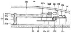
도 4a 및 4b는 도 3에 도시된 라인 Ⅳ-Ⅳ를 따라 취한 단면도로서, 제1 지지 플레이트(101)가 변형되지 않은 상태와 변형된 상태를 각각 보인 도면이며, 도 5는 도 4a에 도시된 힌지 유닛(103)의 구성을 보인 개념도이다.4A and 4B are cross-sectional views taken along the line IV-IV shown in FIG. 3 and show a state in which the
도면들을 참조하면, 힌지 유닛(103)은 경첩 형태로 연결되는 힌지 바(104) 및 힌지 플레이트(105)를 포함한다.Referring to the drawings, the
힌지 바(104)는 제1 지지 플레이트(101)와 연결된다. 힌지 바(104)는 제1 지지 플레이트(101)의 배면으로부터 돌출되는 제1돌출부(101a)에 장착될 수 있다. 제1돌출부(101a)는 펨 너트(pem nut)로 구성되어, 힌지 바(104)를 관통하는 제1체결부재(101b)를 고정시키도록 형성될 수 있다. 상기 구조에 의하면, 힌지 바(104)와 연결되는 힌지 플레이트(105)가 제1 지지 플레이트(101)의 배면으로부터 이격되게 배치되어, 제1 지지 플레이트(101)의 변형을 감안한 소정의 이격거리가 확보될 수 있다.The
힌지 플레이트(105)는 힌지 바(104)에 힌지 결합되고, 제2 지지 플레이트(102)를 지지하도록 구성된다. 제2 지지 플레이트(102)는 힌지 플레이트(105)에 바로 장착될 수도 있고, 도시된 바와 같이 힌지 플레이트(105)에 구비되는 제2돌출부(102a) 상에 장착될 수도 있다. 제2돌출부(102a)는 제1돌출부(101a)와 같이 펨 너트로 구성되어, 제2 지지 플레이트(102)를 관통하는 제2체결부재(102b)를 고정시키도록 형성될 수 있다. 상기 구조에 의하면, 제2 지지 플레이트(102)는 제1 지지 플레이트(101)의 배면으로부터 보다 이격되게 배치되어, 제1 지지 플레이트(101)와 마주보는 제2 지지 플레이트(102)의 전면에 다른 구성(예를 들어, 리드 선, 절연 시트 등)이 장착될 수 있는 공간이 마련될 수 있다.The
제1 지지 플레이트(101)와 제2 지지 플레이트(102) 간의 이격거리는 제1 지지 플레이트(101)의 변형, 제2 지지 플레이트(102)의 처짐, 제1 또는 제2지지 플레이트(101, 102)의 서로 마주보는 면 상에 설치될 수 있는 다른 구성의 높이 등을 고려하여 설정되는 것이 바람직하다.The separation distance between the
힌지 바(104)와 힌지 플레이트(105)는 핀(106)에 의하여 상대 회전 가능하게 결합될 수 있다. 일 예로, 힌지 바(104)는 제1수용부(104a)를 구비하고, 힌지 플레이트(105)는 제1수용부(104a)와 동축 상에 배치되는 제2수용부(105a)를 구비한다. 핀(106)은 제1 및 제2수용부(104a, 105a)에 삽입되어 힌지 바(104)와 힌지 플레이트(105)를 핀(106)을 중심으로 회전 가능하게 연결한다.
힌지 바(104)와 힌지 플레이트(105)는 금속 재질로 형성될 수 있으며, 제1 및 제2수용부(104a, 105a)는 힌지 바(104)와 힌지 플레이트(105)가 각각 벤딩되어 형성될 수 있다. 이와 달리, 힌지 바(104)와 힌지 플레이트(105)는 사출 성형에 의하여 형성될 수도 있다. 본 도면에서는 힌지 바(104)의 단부가 아래로 말린 형태로 형성되어 제1수용부(104a)를 형성하고, 힌지 플레이트(105)의 단부가 위로 말린 형태로 형성되어 제2수용부(105a)를 형성하는 구조를 예시하고 있다.The
앞선 도 3을 함께 참조하면, 힌지 바(104) 및 힌지 플레이트(105)는 핀(106)의 축 방향을 따라 연장되게 형성될 수 있다. 이때, 힌지 유닛(103)의 단부가 핀(106)에 의하여 결합되지 않으면 벌어짐이 발생할 수 있다. 따라서, 힌지 바(104)와 힌지 플레이트(105)가 견고하게 결합될 수 있도록, 제1 및 제2수용부(104a, 105a)는 핀(106)의 축 상에서 핀(106)의 단부를 포함하여 복수의 개소에 배치되는 것이 바람직하다.Referring to FIG. 3 together, the
도 4b를 도 4a와 함께 참조하면, 전면 상의 사용자를 감싸도록 제1 지지 플레이트(101)의 양단부가 전면을 향하여 이동되거나 제1 지지 플레이트(101)의 중앙이 배면을 향하여 이동되면, 힌지 바(104)는 핀(106)을 중심으로 힌지 플레이트(105)에 대하여 상대 회전하게 된다. 반면에, 힌지 플레이트(105)는 제1 지지 플레이트(101)의 변형시에도 그 위치를 유지하여, 힌지 플레이트(105)에 지지되는 제2 지지 플레이트(102)가 평평한 상태로 유지될 수 있다.Referring to FIG. 4B together with FIG. 4A, when both ends of the
따라서, 상기 구조가 플렉서블 디스플레이(180)를 구비하는 영상표시기기(100)에 적용될 경우, 회로기판의 신뢰성 이슈가 해결될 수 있다.Therefore, when the structure is applied to the
한편, 제2 지지 플레이트(102) 상에는 리어 커버(108)가 제2 지지 플레이트(102)를 덮도록 배치된다. 리어 커버(108)는 제1 지지 플레이트(101)의 변형에 따라 함께 변형 가능하게 형성될 수 있다. 이때, 리어 커버(108)는 변형에 의하여 상대적으로 제2 지지 플레이트(102)에 가깝게 위치할 수 있다. 리어 커버(108)는 변형시 제2 지지 플레이트(102)와 접촉되지 않도록, 제2 지지 플레이트(102)의 모서리 또는 제2 지지 플레이트(102)에 장착되는 부품[예를 들어, 본 도면에서는 커넥터(102d)]으로부터 소정 간격을 두고 이격되게 배치되는 것이 바람직하다.On the other hand, the
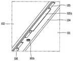
도 6은 도 3에 도시된 A 부분을 3차원으로 보인 사시도이다.FIG. 6 is a perspective view of a portion A shown in FIG. 3 in three dimensions.
힌지 유닛(103)에는 상대 회전 범위를 제한하는 스토퍼(105b)가 구비될 수 있다. 일 예로, 도 6을 앞선 도 4a와 함께 참조하면, 스토퍼(105b)는 힌지 플레이트(105)의 일부가 벤딩된 형태로 형성되며, 힌지 플레이트(105)의 회전시 힌지 바(104)에 걸림되도록 구성된다.The
본 도면에서는 스토퍼(105b)가 힌지 바(104)의 일부를 덮도록 배치된 것을 보이고 있다. 스토퍼(105b)는 힌지 바(104)와 접촉된 상태로 배치되거나 소정 갭(gap)을 두고 이격된 상태로 배치될 수 있다. 상기 구조에 의하면, 힌지 유닛(103)이 음향, 진동 등에 기인한 유동에 의하여 회전 가능하게 설정된 방향과 반대 방향의 회전력을 받는 경우, 스토퍼(105b)가 힌지 바(104)에 걸림되어 상기 회전이 방지될 수 있다.In this figure, it is shown that the
본 도면에는 도시되지 않았지만, 스토퍼(105b)와 힌지 바(104) 사이에는 탄성 변형 가능한 재질로 형성되는 탄성부재(미도시)가 배치될 수 있다. 탄성부재는, 예를 들어, 실리콘, 러버, 스폰지 등이 될 수 있다. 탄성부재가 구비됨으로써, 스토퍼(105b)와 힌지 바(104)의 접촉시 발생할 수 있는 마찰음, 진동 등이 줄어들 수 있다.Although not shown in the drawing, an elastic member (not shown) formed of an elastically deformable material may be disposed between the
한편, 힌지 바(104)에서 스토퍼(105b)에 대응되는 부분에는 돌기(104b)가 형성되어, 스토퍼(105b)와 함께 핀(106)의 적어도 일부를 감싸도록 형성될 수 있다. 상기 구조에 의하면, 제1 및 제2수용부(104a, 105b)를 벗어난 부분에서도 핀(106)의 설치 위치가 한정될 수 있다.The
도 4a를 참조하면, 회로기판으로 구성되는 제2 지지 플레이트(102)의 단부에는 커넥터(102d)가 구비되어 상대 커넥터(102e)와 결합 가능하게 구성될 수 있다. 이때, 힌지 유닛(103)이 커넥터(102d)보다 돌출되게 형성되는 경우, 단차에 의한 간섭이 발생하여 커넥터(102d)와 상대 커넥터(102e) 간의 수평 조립이 불가능하다.Referring to FIG. 4A, a
커넥터(102d)와 상대 커넥터(102e) 간의 수평 연결이 가능하도록, 커넥터(102d)는 제1 지지 플레이트(101)의 배면 상에서 힌지 유닛(103)보다 돌출된 위치에 배치될 수 있다. 본 도면에서는, 커넥터(102d)가 스토퍼(105b)보다 돌출된 위치에 배치된 것을 보이고 있다. 상기 구조에 의하면, 상대 커넥터(102e)가 힌지 유닛(103)과의 간섭 없이 커넥터(102d)에 용이하게 끼워질 수 있다.In order to enable horizontal connection between the
도 7은 힌지 유닛(203)의 변형예를 보인 개념도이다.7 is a conceptual diagram illustrating a modification of the hinge unit 203.
도 7을 참조하면, 힌지 바(204)의 단부가 위로 말린 형태로 형성되어 제1수용부(204a)를 형성하는 구조를 예시하고 있다. 또한, 스토퍼(205b)에 대응되는 단부에는 스토퍼(205b)가 걸림되는 걸림돌기(204b)가 구비된다. 힌지 플레이트(205)는 앞선 실시예와 동일한 구조를 가질 수 있다.Referring to FIG. 7, the end portion of the
앞선 실시예는, 스토퍼(205b)가 힌지 바(204)의 일면에 접촉되어 걸림되는 구조를 가지므로, 스토퍼(205b)가 걸림되는 회전 각도를 변경하기가 어렵다. 반면에 본 변형예에 따를 경우, 걸림돌기(204b)의 길이, 각도 등을 조절하여 스토퍼(205b)가 걸림되는 회전 각도를 용이하게 조절 가능한 장점이 있다.The previous embodiment has a structure in which the
한편, 걸림돌기(204b)는 스토퍼(205b)와 함께 핀(206)의 적어도 일부를 감싸도록 형성될 수 있다. 상기 구조에 의하면, 제1 및 제2수용부(204a, 205b)를 벗어난 부분에서도 핀(206)의 설치 위치가 한정될 수 있다.Meanwhile, the locking
힌지 유닛(103, 203)은 이상에서 설명한 형태에만 한정되는 것은 아니다. 힌지 유닛(103, 203)은 힌지 바(104, 204)와 힌지 플레이트(105, 205)를 상대 회전 가능하게 연결하는 구조라면 어떤 형태로든지 형성될 수 있다.The
도 8은 도 4a에 도시된 홀딩 유닛(107) 부분을 확대하여 보인 단면도이다.FIG. 8 is an enlarged cross-sectional view of a portion of the holding
도 8을 참조하면, 제1 지지 플레이트(101)와 제2 지지 플레이트(102) 사이에는 제2 지지 플레이트(102)의 자중에 의한 처짐을 방지하도록 형성되는 홀딩 유닛(107)이 구비될 수 있다. 홀딩 유닛(107)은 처짐이 발생될 수 있는 제2 지지 플레이트(102)의 가운데 부분에 배치되는 것이 바람직하다. 본 도면에서는 홀딩 유닛(107)이 복수 개로 구비되어 제2 지지 플레이트(102)의 길이 방향을 따라 각각 이격되게 배치된 것을 보이고 있다.Referring to FIG. 8, a holding
홀딩 유닛(107)은 바디(107a) 및 탄성부재(107b)를 포함한다. 바디(107a)는 제1 지지 플레이트(101)에 지지되고, 제2 지지 플레이트(102)에 형성되는 관통홀(102c)을 관통하도록 형성된다. 바디(107a)는 도시된 바와 같이 제1 지지 플레이트(101)에 단순히 안착되도록 구성되거나, 제1 지지 플레이트(101)에 고정된 형태를 가질 수 있다.The holding
탄성부재(107b)는 제1 지지 플레이트(101)와 제2 지지 플레이트(102) 사이에서 바디(107a)를 감싸도록 설치되며, 제2 지지 플레이트(102)를 탄성 가압하도록 형성된다. 따라서, 제2 지지 플레이트(102)의 처짐이 방지될 수 있다. 탄성부재(107b)는, 예를 들어, 스프링, 스폰지 등이 될 수 있다.The
관통홀(102c)을 관통하여 제2 지지 플레이트(102)의 배면으로부터 돌출된 바디(107a)의 일단부에는 반경 방향으로 돌출되어 제2 지지 플레이트(102)의 배면을 덮도록 배치되는 제1이탈방지부(107c)가 형성될 수 있다. 이탈방지부(107c)는 별도의 부재로 구성되어 바디(107a)에 끼워지도록 구성되거나 바디(107a)와 일체로 형성될 수 있다. 또한, 바디(107a)의 타단부에는 탄성부재(107b)가 빠지지 않도록 반경 방향으로 돌출되는 제2이탈방지부(107d)가 구비될 수 있다.A first detachment protruding in a radial direction from one end of the
이처럼, 앞서 설명한 힌지 유닛(103)의 회전 범위를 제한하는 스토퍼(105b), 제2 지지 플레이트(102)의 자중에 의한 처짐을 방지하는 홀딩 유닛(107) 등에 의하여, 신뢰성과 내구성이 확보된 영상표시기기(100)가 제공될 수 있다.As described above, an image having reliability and durability secured by the
도 9는 본 발명의 다른 일 실시예와 관련된 영상표시기기(300)의 배면도이다.9 is a rear view of the image display device 300 according to another embodiment of the present invention.
도 9를 참조하면, 제2 지지 플레이트(302)는 복수 개로 구비되어 일렬로 배치될 수 있다. 본 도면에서는 폭이 거의 동일한 제2 지지 플레이트(302', 302")가 제1 지지 플레이트(301)의 길이 방향을 따라 배열된 것을 보이고 있다.Referring to FIG. 9, a plurality of
제2 지지 플레이트(302', 302")의 양측에 각각 구비되는 힌지 유닛(303)은 일방향[제1 지지 플레이트(301)의 길이 방향에 대응]을 따라 연장되게 형성되어 복수의 제2 지지 플레이트(302', 302")와 각각 연결될 수 있다. 상기 구조에 의하면, 복수의 제2 지지 플레이트(302', 302")가 하나의 힌지 유닛(303)을 공유하는 구조가 구현될 수 있다.
도 10은 본 발명의 또 다른 일 실시예와 관련된 영상표시기기(400)의 배면도이고, 도 11은 도 10에 도시된 라인 XI-XI을 따라 취한 단면도이다.FIG. 10 is a rear view of the image display device 400 according to another exemplary embodiment. FIG. 11 is a cross-sectional view taken along the line XI-XI shown in FIG. 10.
도 10 및 도 11을 참조하면, 제1 지지 플레이트(401)의 배면 상에는 제3 지지 플레이트(409a)가 배치된다. 본 도면에서는 제3 지지 플레이트(409a)가 제2 지지 플레이트(402) 사이에 배치된 일 예를 보이고 있다.10 and 11, a
제3 지지 플레이트(409a)에는 디스플레이(480)와 관련된 제어신호를 생성하도록 형성되는 회로기판(409c)이 장착될 수 있다. 상기 제어신호는 디스플레이(480)의 구동과 관련된 데이터 신호뿐만 아니라 전원신호를 포함한다. 상기 회로기판(409c) 및 이에 장착되는 전자소자(미도시)는 패널(481)을 구동하는 구동 회로부(482)를 구성할 수 있다. 한편, 제3 지지 플레이트(409a)는 그 자체로 회로기판이 될 수도 있다.The
제1 지지 플레이트(401)와 제3 지지 플레이트(409a) 사이에는 제1 지지 플레이트(401)의 변형시 제3 지지 플레이트(409a)의 평평한 상태가 유지될 수 있도록 하는 변형 저감부(409b)가 구비될 수 있다. 변형 저감부(409b)는 제3 지지 플레이트(409a)보다 작은 면적을 가져, 제1 지지 플레이트(401)의 변형시 변형되는 정도가 미미하도록 이루어진다. 따라서, 변형 저감부(409b)에 장착되는 제3 지지 플레이트(409a)의 평평한 상태가 유지될 수 있으며, 제3 지지 플레이트(409a)에 장착되는 회로기판도 평평한 상태로 유지될 수 있다.Between the
변형 저감부(409b)는 제1 지지 플레이트(401)의 변형에 따른 변형이 최소화되도록 변형률이 서로 다른 물질의 조합으로 구성될 수 있다. 예를 들어, 변형 저감부(409b)는 변형률이 서로 다른 물질이 층을 이루도록 배치될 수 있다.The
이상에서 설명한 영상표시기기는 위에서 설명된 실시예들의 구성과 방법에 한정되는 것이 아니라, 상기 실시예들은 다양한 변형이 이루어질 수 있도록 각 실시예들의 전부 또는 일부가 선택적으로 조합되어 구성될 수도 있다.The image display device described above is not limited to the configuration and method of the embodiments described above, but the embodiments may be configured by selectively combining all or some of the embodiments so that various modifications can be made.
Claims (21)
Translated fromKorean상기 디스플레이의 배면을 덮어 지지하고 상기 디스플레이와 함께 변형이 가능한 제1 지지 플레이트;
상기 제1 지지 플레이트의 배면으로부터 이격되게 배치되고, 전자소자가 장착되는 제2 지지 플레이트; 및
상기 제1 지지 플레이트의 변형시 상기 제2 지지 플레이트는 평평한 상태를 유지하도록, 상기 제1 지지 플레이트와 상기 제2 지지 플레이트를 힌지 연결하는 힌지 유닛을 포함하고,
상기 힌지 유닛은 상기 제2 지지 플레이트의 양측에 각각 구비되는 것을 특징으로하는 영상표시기기.A display capable of being transformed into a flat form and a curved form formed to output an image;
A first support plate which covers the back of the display and is deformable with the display;
A second support plate disposed to be spaced apart from a rear surface of the first support plate and on which an electronic device is mounted; And
The second support plate includes a hinge unit hingedly connects the first support plate and the second support plate to maintain a flat state when the first support plate is deformed.
And the hinge units are provided at both sides of the second support plate, respectively.
상기 힌지 유닛은,
상기 제1 지지 플레이트와 연결되는 힌지 바; 및
상기 힌지 바에 힌지 결합되고, 상기 제2 지지 플레이트를 지지하는 힌지 플레이트를 포함하는 것을 특징으로 하는 영상표시기기.The method of claim 1,
The hinge unit,
A hinge bar connected to the first support plate; And
And a hinge plate hinged to the hinge bar and supporting the second support plate.
상기 힌지 플레이트가 상기 제1 지지 플레이트의 배면으로부터 이격되게 배치될 수 있도록, 상기 힌지 바는 상기 제1 지지 플레이트의 배면으로부터 돌출되는 제1돌출부에 장착되는 것을 특징으로 하는 영상표시기기.The method of claim 3,
And the hinge bar is mounted to a first protrusion protruding from the rear surface of the first support plate so that the hinge plate is spaced apart from the rear surface of the first support plate.
상기 제2 지지 플레이트가 상기 제1 지지 플레이트의 배면으로부터 보다 이격되게 배치될 수 있도록, 상기 제2 지지 플레이트는 상기 힌지 플레이트로부터 돌출되는 제2돌출부에 장착되는 것을 특징으로 하는 영상표시기기.The method of claim 4, wherein
And the second support plate is mounted on a second protrusion protruding from the hinge plate so that the second support plate may be disposed further from a rear surface of the first support plate.
상기 힌지 바는 제1수용부를 구비하고,
상기 힌지 플레이트는 상기 제1수용부와 동축 상에 배치되는 제2수용부를 구비하며,
상기 제1 및 제2수용부에는 핀이 삽입되어, 상기 힌지 바와 상기 힌지 플레이트가 상대 회전 가능하게 형성되는 것을 특징으로 하는 영상표시기기.The method of claim 3,
The hinge bar has a first accommodation portion,
The hinge plate has a second accommodating portion disposed coaxially with the first accommodating portion,
And a pin is inserted into the first and second accommodating parts so that the hinge bar and the hinge plate are formed to be relatively rotatable.
상기 힌지 바 및 상기 힌지 플레이트는 상기 핀의 축 방향을 따라 연장되게 형성되고,
상기 제1 및 제2수용부는 상기 핀의 축 상에서 상기 핀의 단부를 포함하여 복수의 개소에 배치되는 것을 특징으로 하는 영상표시기기.The method of claim 6,
The hinge bar and the hinge plate are formed to extend along the axial direction of the pin,
And the first and second accommodating parts are disposed at a plurality of locations including end portions of the pins on the axis of the pins.
상기 힌지 바에 대한 상기 힌지 플레이트의 상대 회전 범위가 제한될 수 있도록, 상기 힌지 플레이트는 일 방향으로의 회전시 상기 힌지 바에 걸림되는 스토퍼를 구비하는 것을 특징으로 하는 영상표시기기.The method of claim 3,
And the hinge plate has a stopper engaged with the hinge bar when the hinge plate is rotated in one direction so that a relative rotation range of the hinge plate with respect to the hinge bar can be limited.
상기 스토퍼는 상기 힌지 바의 일부를 덮도록 배치되는 것을 특징으로 하는 영상표시기기.The method of claim 8,
And the stopper is disposed to cover a portion of the hinge bar.
상기 스토퍼와 상기 힌지 바 사이에는 탄성 변형 가능한 재질로 형성되는 탄성부재가 배치되는 것을 특징으로 하는 영상표시기기.The method of claim 9,
And an elastic member formed of an elastically deformable material between the stopper and the hinge bar.
상기 제2 지지 플레이트는 상기 제1 지지 플레이트의 배면 상에서 상기 스토퍼보다 돌출된 위치에 배치되는 것을 특징으로 하는 영상표시기기.The method of claim 8,
And the second support plate is disposed at a position protruding from the stopper on the rear surface of the first support plate.
Priority Applications (4)
| Application Number | Priority Date | Filing Date | Title |
|---|---|---|---|
| KR1020130064842AKR102072686B1 (en) | 2013-06-05 | 2013-06-05 | Image display device |
| US14/068,601US9477265B2 (en) | 2013-06-05 | 2013-10-31 | Image display device |
| EP13005312.7AEP2811360B1 (en) | 2013-06-05 | 2013-11-11 | Image display device |
| CN201310629788.8ACN104243869B (en) | 2013-06-05 | 2013-11-29 | Image display device |
Applications Claiming Priority (1)
| Application Number | Priority Date | Filing Date | Title |
|---|---|---|---|
| KR1020130064842AKR102072686B1 (en) | 2013-06-05 | 2013-06-05 | Image display device |
Publications (2)
| Publication Number | Publication Date |
|---|---|
| KR20140142989A KR20140142989A (en) | 2014-12-15 |
| KR102072686B1true KR102072686B1 (en) | 2020-02-03 |
Family
ID=49641444
Family Applications (1)
| Application Number | Title | Priority Date | Filing Date |
|---|---|---|---|
| KR1020130064842AActiveKR102072686B1 (en) | 2013-06-05 | 2013-06-05 | Image display device |
Country Status (4)
| Country | Link |
|---|---|
| US (1) | US9477265B2 (en) |
| EP (1) | EP2811360B1 (en) |
| KR (1) | KR102072686B1 (en) |
| CN (1) | CN104243869B (en) |
Cited By (1)
| Publication number | Priority date | Publication date | Assignee | Title |
|---|---|---|---|---|
| WO2021230399A1 (en)* | 2020-05-14 | 2021-11-18 | 엘지전자 주식회사 | Display device |
Families Citing this family (6)
| Publication number | Priority date | Publication date | Assignee | Title |
|---|---|---|---|---|
| KR102072686B1 (en)* | 2013-06-05 | 2020-02-03 | 엘지전자 주식회사 | Image display device |
| KR102208441B1 (en)* | 2014-06-13 | 2021-01-27 | 삼성전자주식회사 | An electronic device including a screen |
| US9540136B2 (en)* | 2014-08-22 | 2017-01-10 | Caterpillar Inc. | Control box for generator set |
| KR102292515B1 (en)* | 2015-04-24 | 2021-08-23 | 삼성디스플레이 주식회사 | Flexible display device |
| KR102501909B1 (en)* | 2018-04-20 | 2023-02-20 | 엘지디스플레이 주식회사 | Display apparatus |
| WO2023171914A1 (en)* | 2022-03-10 | 2023-09-14 | 삼성전자주식회사 | Electronic device comprising fastening member |
Citations (1)
| Publication number | Priority date | Publication date | Assignee | Title |
|---|---|---|---|---|
| JP2008147784A (en)* | 2006-12-06 | 2008-06-26 | Sharp Corp | Hinge, board mounting plate and display device |
Family Cites Families (14)
| Publication number | Priority date | Publication date | Assignee | Title |
|---|---|---|---|---|
| FI111998B (en)* | 1999-12-08 | 2003-10-15 | Nokia Corp | User interface |
| KR100383801B1 (en)* | 2000-09-19 | 2003-05-16 | 주식회사 에이콤이피 | Liquid Crystal Display Device |
| EP1565900B1 (en) | 2002-11-21 | 2013-04-10 | Creator Technology B.V. | Flexible display |
| CN100363960C (en)* | 2002-11-21 | 2008-01-23 | 皇家飞利浦电子股份有限公司 | flexible display |
| US20130100392A1 (en) | 2010-06-29 | 2013-04-25 | Sharp Kabushiki Kaisha | Flexible display device and method for manufacturing flexible display device |
| US20120032981A1 (en)* | 2010-08-04 | 2012-02-09 | Tina Hackwell | Electronic Book With Configurable Display Panels |
| KR20120072864A (en)* | 2010-12-24 | 2012-07-04 | 삼성전자주식회사 | Display apparatus |
| WO2012129247A2 (en) | 2011-03-21 | 2012-09-27 | Apple Inc. | Electronic devices with flexible displays |
| TWI449991B (en)* | 2011-03-21 | 2014-08-21 | Wistron Corp | Display and an electronic device having the same |
| EP2546720B1 (en)* | 2011-07-11 | 2018-09-26 | Samsung Electronics Co., Ltd. | Flexible display with display support |
| US8811032B2 (en)* | 2011-08-05 | 2014-08-19 | Blackberry Limited | Handheld electronic device having a flexible display |
| US8929085B2 (en)* | 2011-09-30 | 2015-01-06 | Apple Inc. | Flexible electronic devices |
| US9711752B2 (en)* | 2011-12-19 | 2017-07-18 | Lg Electronics Inc. | Display apparatus |
| KR102072686B1 (en)* | 2013-06-05 | 2020-02-03 | 엘지전자 주식회사 | Image display device |
- 2013
- 2013-06-05KRKR1020130064842Apatent/KR102072686B1/enactiveActive
- 2013-10-31USUS14/068,601patent/US9477265B2/enactiveActive
- 2013-11-11EPEP13005312.7Apatent/EP2811360B1/enactiveActive
- 2013-11-29CNCN201310629788.8Apatent/CN104243869B/enactiveActive
Patent Citations (1)
| Publication number | Priority date | Publication date | Assignee | Title |
|---|---|---|---|---|
| JP2008147784A (en)* | 2006-12-06 | 2008-06-26 | Sharp Corp | Hinge, board mounting plate and display device |
Cited By (4)
| Publication number | Priority date | Publication date | Assignee | Title |
|---|---|---|---|---|
| WO2021230399A1 (en)* | 2020-05-14 | 2021-11-18 | 엘지전자 주식회사 | Display device |
| KR20230010222A (en)* | 2020-05-14 | 2023-01-18 | 엘지전자 주식회사 | display device |
| US11655935B2 (en) | 2020-05-14 | 2023-05-23 | Lg Electronics Inc. | Display device |
| KR102847145B1 (en) | 2020-05-14 | 2025-08-14 | 엘지전자 주식회사 | display device |
Also Published As
| Publication number | Publication date |
|---|---|
| CN104243869A (en) | 2014-12-24 |
| CN104243869B (en) | 2017-12-22 |
| EP2811360B1 (en) | 2018-07-11 |
| EP2811360A3 (en) | 2014-12-17 |
| US9477265B2 (en) | 2016-10-25 |
| KR20140142989A (en) | 2014-12-15 |
| EP2811360A2 (en) | 2014-12-10 |
| US20140362541A1 (en) | 2014-12-11 |
Similar Documents
| Publication | Publication Date | Title |
|---|---|---|
| KR102072686B1 (en) | Image display device | |
| US9311843B2 (en) | Image display device | |
| US9536456B2 (en) | Image display device | |
| KR102193921B1 (en) | Image display device | |
| US9801291B2 (en) | Image display device | |
| KR102091517B1 (en) | Image display device | |
| US9560776B2 (en) | Image display device | |
| US9467640B2 (en) | Image display device and image display system | |
| KR102251090B1 (en) | Image display device and method thereof | |
| KR20150088605A (en) | Image display device | |
| KR102091518B1 (en) | Image display device | |
| KR102070280B1 (en) | Image display device | |
| KR102130538B1 (en) | Image display device | |
| KR20160059842A (en) | Display device | |
| KR20160012782A (en) | Input module and image display device having the same | |
| KR20150116283A (en) | Image display device | |
| KR20160059843A (en) | Display device having speaker |
Legal Events
| Date | Code | Title | Description |
|---|---|---|---|
| PA0109 | Patent application | Patent event code:PA01091R01D Comment text:Patent Application Patent event date:20130605 | |
| PG1501 | Laying open of application | ||
| PA0201 | Request for examination | Patent event code:PA02012R01D Patent event date:20180605 Comment text:Request for Examination of Application Patent event code:PA02011R01I Patent event date:20130605 Comment text:Patent Application | |
| E902 | Notification of reason for refusal | ||
| PE0902 | Notice of grounds for rejection | Comment text:Notification of reason for refusal Patent event date:20190531 Patent event code:PE09021S01D | |
| E701 | Decision to grant or registration of patent right | ||
| PE0701 | Decision of registration | Patent event code:PE07011S01D Comment text:Decision to Grant Registration Patent event date:20191107 | |
| GRNT | Written decision to grant | ||
| PR0701 | Registration of establishment | Comment text:Registration of Establishment Patent event date:20200128 Patent event code:PR07011E01D | |
| PR1002 | Payment of registration fee | Payment date:20200129 End annual number:3 Start annual number:1 | |
| PG1601 | Publication of registration | ||
| PR1001 | Payment of annual fee | Payment date:20221222 Start annual number:4 End annual number:4 |