KR102071435B1 - Energy storage device and conductive member - Google Patents
Energy storage device and conductive memberDownload PDFInfo
- Publication number
- KR102071435B1 KR102071435B1KR1020130061501AKR20130061501AKR102071435B1KR 102071435 B1KR102071435 B1KR 102071435B1KR 1020130061501 AKR1020130061501 AKR 1020130061501AKR 20130061501 AKR20130061501 AKR 20130061501AKR 102071435 B1KR102071435 B1KR 102071435B1
- Authority
- KR
- South Korea
- Prior art keywords
- case
- body portion
- conductive member
- caulking
- wall surface
- Prior art date
- Legal status (The legal status is an assumption and is not a legal conclusion. Google has not performed a legal analysis and makes no representation as to the accuracy of the status listed.)
- Active
Links
Images


Classifications
- H—ELECTRICITY
- H01—ELECTRIC ELEMENTS
- H01M—PROCESSES OR MEANS, e.g. BATTERIES, FOR THE DIRECT CONVERSION OF CHEMICAL ENERGY INTO ELECTRICAL ENERGY
- H01M50/00—Constructional details or processes of manufacture of the non-active parts of electrochemical cells other than fuel cells, e.g. hybrid cells
- H01M50/50—Current conducting connections for cells or batteries
- H01M50/543—Terminals
- H—ELECTRICITY
- H01—ELECTRIC ELEMENTS
- H01G—CAPACITORS; CAPACITORS, RECTIFIERS, DETECTORS, SWITCHING DEVICES, LIGHT-SENSITIVE OR TEMPERATURE-SENSITIVE DEVICES OF THE ELECTROLYTIC TYPE
- H01G11/00—Hybrid capacitors, i.e. capacitors having different positive and negative electrodes; Electric double-layer [EDL] capacitors; Processes for the manufacture thereof or of parts thereof
- H01G11/66—Current collectors
- H01G11/70—Current collectors characterised by their structure
- H—ELECTRICITY
- H01—ELECTRIC ELEMENTS
- H01G—CAPACITORS; CAPACITORS, RECTIFIERS, DETECTORS, SWITCHING DEVICES, LIGHT-SENSITIVE OR TEMPERATURE-SENSITIVE DEVICES OF THE ELECTROLYTIC TYPE
- H01G11/00—Hybrid capacitors, i.e. capacitors having different positive and negative electrodes; Electric double-layer [EDL] capacitors; Processes for the manufacture thereof or of parts thereof
- H01G11/74—Terminals, e.g. extensions of current collectors
- H—ELECTRICITY
- H01—ELECTRIC ELEMENTS
- H01G—CAPACITORS; CAPACITORS, RECTIFIERS, DETECTORS, SWITCHING DEVICES, LIGHT-SENSITIVE OR TEMPERATURE-SENSITIVE DEVICES OF THE ELECTROLYTIC TYPE
- H01G11/00—Hybrid capacitors, i.e. capacitors having different positive and negative electrodes; Electric double-layer [EDL] capacitors; Processes for the manufacture thereof or of parts thereof
- H01G11/78—Cases; Housings; Encapsulations; Mountings
- H01G11/82—Fixing or assembling a capacitive element in a housing, e.g. mounting electrodes, current collectors or terminals in containers or encapsulations
- H—ELECTRICITY
- H01—ELECTRIC ELEMENTS
- H01M—PROCESSES OR MEANS, e.g. BATTERIES, FOR THE DIRECT CONVERSION OF CHEMICAL ENERGY INTO ELECTRICAL ENERGY
- H01M10/00—Secondary cells; Manufacture thereof
- H01M10/04—Construction or manufacture in general
- H—ELECTRICITY
- H01—ELECTRIC ELEMENTS
- H01M—PROCESSES OR MEANS, e.g. BATTERIES, FOR THE DIRECT CONVERSION OF CHEMICAL ENERGY INTO ELECTRICAL ENERGY
- H01M4/00—Electrodes
- H01M4/02—Electrodes composed of, or comprising, active material
- H01M4/64—Carriers or collectors
- H01M4/70—Carriers or collectors characterised by shape or form
- H—ELECTRICITY
- H01—ELECTRIC ELEMENTS
- H01M—PROCESSES OR MEANS, e.g. BATTERIES, FOR THE DIRECT CONVERSION OF CHEMICAL ENERGY INTO ELECTRICAL ENERGY
- H01M50/00—Constructional details or processes of manufacture of the non-active parts of electrochemical cells other than fuel cells, e.g. hybrid cells
- H01M50/10—Primary casings; Jackets or wrappings
- H01M50/172—Arrangements of electric connectors penetrating the casing
- H01M50/174—Arrangements of electric connectors penetrating the casing adapted for the shape of the cells
- H01M50/176—Arrangements of electric connectors penetrating the casing adapted for the shape of the cells for prismatic or rectangular cells
- H—ELECTRICITY
- H01—ELECTRIC ELEMENTS
- H01M—PROCESSES OR MEANS, e.g. BATTERIES, FOR THE DIRECT CONVERSION OF CHEMICAL ENERGY INTO ELECTRICAL ENERGY
- H01M50/00—Constructional details or processes of manufacture of the non-active parts of electrochemical cells other than fuel cells, e.g. hybrid cells
- H01M50/50—Current conducting connections for cells or batteries
- H01M50/528—Fixed electrical connections, i.e. not intended for disconnection
- H—ELECTRICITY
- H01—ELECTRIC ELEMENTS
- H01M—PROCESSES OR MEANS, e.g. BATTERIES, FOR THE DIRECT CONVERSION OF CHEMICAL ENERGY INTO ELECTRICAL ENERGY
- H01M50/00—Constructional details or processes of manufacture of the non-active parts of electrochemical cells other than fuel cells, e.g. hybrid cells
- H01M50/50—Current conducting connections for cells or batteries
- H01M50/531—Electrode connections inside a battery casing
- H—ELECTRICITY
- H01—ELECTRIC ELEMENTS
- H01M—PROCESSES OR MEANS, e.g. BATTERIES, FOR THE DIRECT CONVERSION OF CHEMICAL ENERGY INTO ELECTRICAL ENERGY
- H01M50/00—Constructional details or processes of manufacture of the non-active parts of electrochemical cells other than fuel cells, e.g. hybrid cells
- H01M50/50—Current conducting connections for cells or batteries
- H01M50/543—Terminals
- H01M50/547—Terminals characterised by the disposition of the terminals on the cells
- H01M50/55—Terminals characterised by the disposition of the terminals on the cells on the same side of the cell
- H—ELECTRICITY
- H01—ELECTRIC ELEMENTS
- H01M—PROCESSES OR MEANS, e.g. BATTERIES, FOR THE DIRECT CONVERSION OF CHEMICAL ENERGY INTO ELECTRICAL ENERGY
- H01M50/00—Constructional details or processes of manufacture of the non-active parts of electrochemical cells other than fuel cells, e.g. hybrid cells
- H01M50/50—Current conducting connections for cells or batteries
- H01M50/543—Terminals
- H01M50/564—Terminals characterised by their manufacturing process
- H01M50/567—Terminals characterised by their manufacturing process by fixing means, e.g. screws, rivets or bolts
- H—ELECTRICITY
- H01—ELECTRIC ELEMENTS
- H01M—PROCESSES OR MEANS, e.g. BATTERIES, FOR THE DIRECT CONVERSION OF CHEMICAL ENERGY INTO ELECTRICAL ENERGY
- H01M10/00—Secondary cells; Manufacture thereof
- H01M10/05—Accumulators with non-aqueous electrolyte
- H01M10/052—Li-accumulators
- H—ELECTRICITY
- H01—ELECTRIC ELEMENTS
- H01M—PROCESSES OR MEANS, e.g. BATTERIES, FOR THE DIRECT CONVERSION OF CHEMICAL ENERGY INTO ELECTRICAL ENERGY
- H01M10/00—Secondary cells; Manufacture thereof
- H01M10/34—Gastight accumulators
- H01M10/345—Gastight metal hydride accumulators
- H—ELECTRICITY
- H01—ELECTRIC ELEMENTS
- H01M—PROCESSES OR MEANS, e.g. BATTERIES, FOR THE DIRECT CONVERSION OF CHEMICAL ENERGY INTO ELECTRICAL ENERGY
- H01M2220/00—Batteries for particular applications
- H01M2220/20—Batteries in motive systems, e.g. vehicle, ship, plane
- H—ELECTRICITY
- H01—ELECTRIC ELEMENTS
- H01M—PROCESSES OR MEANS, e.g. BATTERIES, FOR THE DIRECT CONVERSION OF CHEMICAL ENERGY INTO ELECTRICAL ENERGY
- H01M2220/00—Batteries for particular applications
- H01M2220/30—Batteries in portable systems, e.g. mobile phone, laptop
- Y—GENERAL TAGGING OF NEW TECHNOLOGICAL DEVELOPMENTS; GENERAL TAGGING OF CROSS-SECTIONAL TECHNOLOGIES SPANNING OVER SEVERAL SECTIONS OF THE IPC; TECHNICAL SUBJECTS COVERED BY FORMER USPC CROSS-REFERENCE ART COLLECTIONS [XRACs] AND DIGESTS
- Y02—TECHNOLOGIES OR APPLICATIONS FOR MITIGATION OR ADAPTATION AGAINST CLIMATE CHANGE
- Y02E—REDUCTION OF GREENHOUSE GAS [GHG] EMISSIONS, RELATED TO ENERGY GENERATION, TRANSMISSION OR DISTRIBUTION
- Y02E60/00—Enabling technologies; Technologies with a potential or indirect contribution to GHG emissions mitigation
- Y02E60/10—Energy storage using batteries
- Y—GENERAL TAGGING OF NEW TECHNOLOGICAL DEVELOPMENTS; GENERAL TAGGING OF CROSS-SECTIONAL TECHNOLOGIES SPANNING OVER SEVERAL SECTIONS OF THE IPC; TECHNICAL SUBJECTS COVERED BY FORMER USPC CROSS-REFERENCE ART COLLECTIONS [XRACs] AND DIGESTS
- Y02—TECHNOLOGIES OR APPLICATIONS FOR MITIGATION OR ADAPTATION AGAINST CLIMATE CHANGE
- Y02E—REDUCTION OF GREENHOUSE GAS [GHG] EMISSIONS, RELATED TO ENERGY GENERATION, TRANSMISSION OR DISTRIBUTION
- Y02E60/00—Enabling technologies; Technologies with a potential or indirect contribution to GHG emissions mitigation
- Y02E60/13—Energy storage using capacitors
- Y—GENERAL TAGGING OF NEW TECHNOLOGICAL DEVELOPMENTS; GENERAL TAGGING OF CROSS-SECTIONAL TECHNOLOGIES SPANNING OVER SEVERAL SECTIONS OF THE IPC; TECHNICAL SUBJECTS COVERED BY FORMER USPC CROSS-REFERENCE ART COLLECTIONS [XRACs] AND DIGESTS
- Y02—TECHNOLOGIES OR APPLICATIONS FOR MITIGATION OR ADAPTATION AGAINST CLIMATE CHANGE
- Y02P—CLIMATE CHANGE MITIGATION TECHNOLOGIES IN THE PRODUCTION OR PROCESSING OF GOODS
- Y02P70/00—Climate change mitigation technologies in the production process for final industrial or consumer products
- Y02P70/50—Manufacturing or production processes characterised by the final manufactured product
Landscapes
- Chemical & Material Sciences (AREA)
- Chemical Kinetics & Catalysis (AREA)
- Electrochemistry (AREA)
- General Chemical & Material Sciences (AREA)
- Engineering & Computer Science (AREA)
- Power Engineering (AREA)
- Microelectronics & Electronic Packaging (AREA)
- Manufacturing & Machinery (AREA)
- Connection Of Batteries Or Terminals (AREA)
- Sealing Battery Cases Or Jackets (AREA)
- Electric Double-Layer Capacitors Or The Like (AREA)
Abstract
Translated fromKoreanDescription
Translated fromKorean본 발명은 축전 소자 및 도전성 부재에 관한 것이다.The present invention relates to a power storage element and a conductive member.
최근, 차량(자동차, 자동 이륜차 등), 또는 각종 기기(휴대 단말기, 노트북형 PC 등)의 동력원으로서, 충방전 가능한 축전 소자가 채용되고 있다. 축전 소자에는, 예를 들면, 전지(리튬 이온 전지, 니켈 수소 전지 등), 및 커패시터(전기 이중 층 커패시터 등)가 있다.In recent years, as a power source for vehicles (cars, motorcycles, etc.) or various devices (portable terminals, notebook PCs, etc.), power storage elements capable of charging and discharging have been adopted. Examples of the power storage element include a battery (lithium ion battery, nickel hydrogen battery, etc.), and a capacitor (electric double layer capacitor, etc.).
예를 들면, 전지는, 전극체와 케이스를 구비한다. 케이스는 전극체를 수용하는 케이스 본체, 및 케이스 본체의 개구부를 막는 커버판을 가진다. 전극체와, 전극체에 접속된 집전체가 케이스 내에 배치된다. 외부 단자는, 예를 들면, 커버판의 외면에 배치된다. 외부 단자와 집전체는 직접적 또는 간접적으로 접속된다. 이로써, 외부 단자와 전극체가 전기적으로 접속된다.For example, a battery is provided with an electrode body and a case. The case has a case body for accommodating an electrode body, and a cover plate for blocking an opening of the case body. The electrode body and the current collector connected to the electrode body are disposed in the case. The external terminal is disposed on the outer surface of the cover plate, for example. The external terminal and the current collector are connected directly or indirectly. As a result, the external terminal and the electrode body are electrically connected.
외부 단자와 집전체를 전기적으로 접속하는 부재로서, 예를 들면, 도전성 부재가 사용된다. 도전성 부재는, 예를 들면, 보디부(body portion)와, 보조 단자와, 접속 도체를 구비한다. 보조 단자는 보디부의 하면에서 돌출되는 제1 코킹(caulking)부, 및 보디부의 상면에서 돌출되는 제2 코킹부를 구비한다. 접속 도체는 2개의 관통 구멍을 가진다. 한쪽의 관통 구멍에는 보조 단자의 제2 코킹부가 삽입관통된다. 다른 쪽의 관통 구멍에는 외부 단자의 축부가 삽입관통된다.As a member which electrically connects an external terminal and an electrical power collector, a conductive member is used, for example. The conductive member includes, for example, a body portion, an auxiliary terminal, and a connection conductor. The auxiliary terminal has a first caulking portion protruding from the lower surface of the body portion, and a second caulking portion protruding from the upper surface of the body portion. The connecting conductor has two through holes. The second caulking portion of the auxiliary terminal is inserted through one of the through holes. The shaft portion of the external terminal is inserted through the other through hole.
일본 공개특허공보 제2010-097764호(특허문헌 1)에 기재된 전지는, 보조 단자(8)와, 외부 단자(4)와, 접속 도체(9)를 구비한다. 보조 단자는 보디부(시트부(8a))와, 제1 코킹부(제1 코킹 통(8b))와, 제2 코킹부(제2 코킹 통(8c))를 구비한다. 외부 단자(4)는 헤드부(시트부(4a))와 수나사부(볼트부(4b))를 구비한다. 접속 도체(9)는 관통 구멍(코킹 구멍(9a) 및 단자 관통 구멍(9b))을 구비한다.The battery described in JP 2010-097764 A (Patent Document 1) includes an
밀봉 부재(외부 절연 밀봉재(6))를 통하여, 커버판(3)의 외면에, 보조 단자가 배치된다. 이로써, 보조 단자의 제1 코킹부가, 케이스 내의 집전체(집전 접속체(5))의 관통 구멍에 삽입관통된다. 관통 구멍에서 아래쪽으로 돌출하는, 제1 코킹부의 선단 부분은, 아래쪽에서 코킹되어 있다.The auxiliary terminal is arranged on the outer surface of the
또한, 밀봉 부재, 또는 밀봉 부재와는 별도로 설치된 단자 회전 방지 부재를 통하여, 커버판의 외면에, 외부 단자가 배치된다. 보조 단자의 제2 코킹부와 외부 단자의 수나사부가 접속 도체의 관통 구멍 각각에 삽입관통된다. 한쪽의 관통 구멍(코킹 구멍(9a))에서 위쪽으로 돌출되는, 제2 코킹부의 선단 부분이, 위쪽에서 코킹되어 있다. 이로써, 외부 단자와 집전체가, 보조 단자 및 접속 도체를 통하여, 전기적으로 접속된다.Moreover, an external terminal is arrange | positioned on the outer surface of a cover plate through the sealing member or the terminal rotation prevention member provided separately from the sealing member. The second caulking portion of the auxiliary terminal and the male screw portion of the external terminal are inserted through each of the through holes of the connecting conductor. A tip portion of the second caulking portion projecting upward from one through hole (caulking hole 9a) is caulked from above. Thereby, an external terminal and an electrical power collector are electrically connected through an auxiliary terminal and a connection conductor.
그런데, 특허 문헌 1에 기재된 전지에서는, 접속 도체의 관통 구멍에 삽입관통된 제2 코킹부에, 코킹 처리가 행해진다. 이 코킹 처리에 의해, 보조 단자와 접속 도체가 일체화된다. 그 후, 제1 코킹부가 케이스의 격벽에 삽입관통된다. 케이스의 격벽 및 집전체의 관통 구멍에 삽입관통된 제1 코킹부에, 코킹 처리가 행해진다. 그때, 일체화된 보조 단자와 접속 도체가, 제1 코킹부를 코킹하고 있을 때 발생하는, 코킹 작용력에 의해, 삽입관통 방향을 회전축으로 하여 회전하는 경우가 있다. 그러므로, 접속 도체가 바람직한 위치로부터 어긋나는 경우가 있다.By the way, in the battery of
이 종류의 문제는 전지에 한정되지 않고, 커패시터(전기 이중층 커패시터 등)에 있어서도 발생할 가능성이 있다.This kind of problem is not limited to a battery, but may occur in a capacitor (electric double layer capacitor, etc.).
본 발명은, 이러한 문제를 감안하여 이루어진 것이다. 본 발명에서의 하나의 목적은, 도전성 부재가 코킹될 때, 도전성 부재가 케이스에 대하여 회전하는 것을 억제 또는 방지할 수 있는 축전 소자 및 도전성 부재를 제공하는 것에 있다.This invention is made | formed in view of such a problem. One object of the present invention is to provide a power storage element and a conductive member which can suppress or prevent the conductive member from rotating relative to the case when the conductive member is caulked.
본 발명에 따른 축전 소자는,The power storage device according to the present invention,
서로 절연된 양극판과 음극판을 포함하는 전극체;An electrode body including a positive electrode plate and a negative electrode plate insulated from each other;
전극체를 수용하는 케이스; 및A case accommodating the electrode body; And
케이스 내에서 전극체와 전기적으로 접속되는 도전성 부재를 포함하고,A conductive member electrically connected to the electrode body in the case;
도전성 부재는,The conductive member is
케이스의 벽면을 관통하는 방향으로 중심축을 가지는, 본체부; 및A main body having a central axis in a direction penetrating the wall surface of the case; And
상기 본체부에서 상기 중심축과 교차하는 방향으로 돌출되는 도체 접속부를 포함하고,A conductor connecting portion protruding from the main body portion in a direction crossing the central axis,
본체부는,The body part,
상기 본체부의 한쪽의 단부에 설치되고, 케이스의 벽면에 삽입관통되는 코킹부; 및A caulking portion installed at one end of the main body portion and inserted through the wall surface of the case; And
상기 본체부의 다른 쪽의 단부에 설치된, 중심축에 대하여 비(非) 원형상이 되는 헤드부를 포함한다.And a head portion provided in the other end portion of the main body portion in a non-circular shape with respect to the central axis.
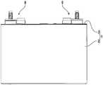
도 1은 본 발명의 일 실시예에 따른 전지의 사시도를 나타낸다.
도 2는 상기 전지의 측면도를 나타낸다.
도 3은 상기 전지의, 도 1에 나타낸 A-A선 단면도를 나타낸다.
도 4는 상기 전지의, 도 1에 나타낸 B-B선 단면도를 나타낸다.
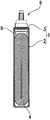
도 5는 상기 전지의 단자 구조의 확대 단면도를 나타낸다.
도 6은 상기 전지를 위쪽에서 보았을 때의, 단자 구조의 분해 사시도를 나타낸다.
도 7은 상기 전지를 아래쪽에서 보았을 때의, 단자 구조의 분해 사시도를 나타낸다.
도 8은 본 발명의 다른 실시예에 따른 전지의 사시도를 나타낸다.
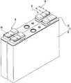
도 9는 본 발명의 또 다른 실시예에 따른 전지를 위쪽에서 보았을 때의, 단자 구조의 분해 사시도를 나타낸다.1 is a perspective view of a battery according to an embodiment of the present invention.
2 shows a side view of the battery.
3 is a cross-sectional view taken along the line AA of FIG. 1.
4 is a cross-sectional view taken along the line BB of FIG. 1.
5 is an enlarged cross-sectional view of the terminal structure of the battery.
6 shows an exploded perspective view of the terminal structure when the battery is viewed from above.
7 shows an exploded perspective view of the terminal structure when the battery is viewed from below.
8 is a perspective view of a battery according to another embodiment of the present invention.
9 is an exploded perspective view of a terminal structure when the battery according to another embodiment of the present invention is viewed from above.
본 발명에 따른 축전 소자(본 축전 소자)는,The electrical storage element (this electrical storage element) which concerns on this invention,
서로 절연된 양극판과 음극판을 포함하는 전극체;An electrode body including a positive electrode plate and a negative electrode plate insulated from each other;
전극체를 수용하는 케이스; 및A case accommodating the electrode body; And
케이스 내에서 전극체와 전기적으로 접속되는 도전성 부재를 구비하고,A conductive member electrically connected to the electrode body in the case;
도전성 부재는,The conductive member is
케이스의 벽면을 관통하는 방향으로 중심축을 가지는 본체부; 및A main body part having a central axis in a direction penetrating the wall surface of the case; And
상기 본체부로부터 중심축과 교차하는 방향으로 돌출하는 도체 접속부를 구비하고,A conductor connecting portion protruding from the main body portion in a direction crossing the central axis,
본체부는,The body part,
상기 본체부의 한쪽의 단부에 설치되고, 케이스의 벽면에 삽입관통되는 코킹부; 및A caulking portion installed at one end of the main body portion and inserted through the wall surface of the case; And
상기 본체부의 다른 쪽의 단부에 설치된, 중심축에 대하여 비 원형상의 헤드부를 구비한다.The non-circular head part is provided with respect to the central axis provided in the other end part of the said main body part.
이러한 구성에 의하면, 본체부의 헤드부는, 비 원형상이다. 그러므로, 헤드부를 공구 또는 지그 등의 도구에 의해 지지하는 것이 가능해진다. 따라서, 이 축전 소자에서는, 헤드부가 지지된 상태로, 코킹부에 코킹 처리가 행해진다. 따라서, 코킹부를 코킹할 때 발생하는 코킹 작용력이, 도전성 부재를 중심축 주위에 회전시키는 것이 억제 또는 규제된다. 이로써, 코킹 시에, 도전성 부재가 케이스에 대하여 회전하는 것을 억제 또는 방지할 수 있다.According to such a structure, the head part of a main-body part is non-circular shape. Therefore, the head portion can be supported by a tool such as a tool or a jig. Therefore, in this power storage element, the caulking process is performed on the caulking portion while the head portion is supported. Therefore, the caulking action force generated when caulking the caulking portion is suppressed or restricted from rotating the conductive member about the central axis. Thereby, at the time of caulking, it can suppress or prevent rotation of a conductive member with respect to a case.
또한, 이러한 구성에 의하면, 도체 접속부가 본체부에서 이격되는 방향으로 전개된다(연장된다). 이로써, 도체 접속부에 대한 도체의 접속 공간을 충분히 확보할 수 있다.Moreover, according to such a structure, the conductor connection part expands (extends) in the direction away from a main body part. Thereby, the connection space of a conductor with respect to a conductor connection part can be fully ensured.
또한, 본 축전 소자 다른 태양은 절연 부재를 더 구비하고 있어도 된다. 이 절연 부재는, 케이스의 벽면을 따라 배치되고, 코킹부가 관통하기 위한 관통 구멍을 가지는 동시에, 도전성 부재를 지지한다.In addition, another embodiment of the power storage element may further include an insulating member. This insulating member is disposed along the wall surface of the case, has a through hole for penetrating the caulking portion, and supports the conductive member.
이러한 구성에 의하면, 절연 부재에 의해, 도전성 부재와 케이스의 벽면이 절연된다. 이 상태에서, 도전성 부재와 전극체를 전기적으로 접속할 수 있다.According to such a structure, the electrically insulating member and the wall surface of a case are insulated by the insulating member. In this state, the conductive member and the electrode body can be electrically connected.
이 경우, 본체부는, 코킹부와 헤드부 사이에 보디부를 더 구비하고 있어도 된다. 또한, 절연 부재는 보디부를 받아들일 수 있는 오목부를 구비하고 있어도 된다.In this case, the main body portion may further include a body portion between the caulking portion and the head portion. Moreover, the insulating member may be provided with the recessed part which can receive a body part.
이러한 구성에 의하면, 본 축전 소자가 결로 등에 의해 발생하는 물방울, 또는 도전성 분위기(정전기나 먼지(dust))에 노출된 경우라도, 절연 부재의 외벽부가 커버(또는 차단벽)이 된다. 이로써, 케이스와 본체부 사이의 단락(短絡)을 바람직하게 억제 또는 방지할 수 있다.According to such a structure, even when this power storage element is exposed to the water droplets generated by condensation or the like, or to an electrically conductive atmosphere (electrostatic or dust), the outer wall portion of the insulating member becomes a cover (or a blocking wall). Thereby, short circuit between a case and a main-body part can be suppressed or prevented preferably.
또한 이 경우, 헤드부와 보디부의, 중심축에 거의 수직인 단면의 형상이 거의 동일해도 된다.In this case, the shape of the cross section substantially perpendicular to the central axis of the head portion and the body portion may be substantially the same.
이러한 구성에 의하면, 헤드부와 보디부 사이에 불필요한 단차가 생기는 것을 없앨 수가 있다.According to such a structure, unnecessary step | step difference arises between a head part and a body part.
또한, 본 축전 소자의 다른 태양에서는, 헤드부는, 코너부가 둥글게 된 다각 형상을 가져도 된다.Moreover, in another aspect of this power storage element, the head portion may have a polygonal shape in which the corner portion is rounded.
이러한 구성에 의하면, 헤드부가 다각 형상이므로, 도구에 의해, 헤드부를 확실하게 지지할 수 있다. 또한, 헤드부의 코너부가 둥글게 되어 있으므로, 그 부분에서의 전기 저항값이 국소적으로 높아지는 것을 억제 또는 방지할 수 있다.According to such a structure, since a head part is polygonal shape, a tool can reliably support a head part. In addition, since the corner portion of the head portion is rounded, it is possible to suppress or prevent the increase in the electric resistance value at that portion locally.
또한, 본 축전 소자의 또 다른 태양에서는, 코킹부는 케이스의 바깥쪽에서 안쪽을 향해 케이스의 벽면에 삽입관통되고, 도체 접속부는 케이스 밖에 배치되어 있어도 된다.Moreover, in another aspect of this power storage element, the caulking portion may be inserted through the wall surface of the case from the outside of the case to the inside, and the conductor connecting portion may be disposed outside the case.
이러한 구성에 의하면, 코킹부가 케이스의 안쪽으로부터 코킹됨으로써, 도전성 부재가 케이스에 고정된다. 한편, 도체는 케이스 밖에 배치된 도체 접속부에 접속된다.According to this structure, the conductive member is fixed to the case by caulking from the inside of the case. On the other hand, a conductor is connected to the conductor connection part arrange | positioned outside the case.
이 경우, 본 축전 소자는 케이스 밖에 배치되는 외부 단자를 더 포함하고, 도체 접속부는 외부 단자와 전기적으로 접속되어 있어도 된다.In this case, this electrical storage element may further include the external terminal arrange | positioned outside a case, and the conductor connection part may be electrically connected with the external terminal.
이러한 구성에 의하면, 도체로서의 외부 단자가 도체 접속부에 접속된다. 외부 단자에는, 예를 들면, 외부 기기의 리드선의 압착 단자가 접속된다.According to such a structure, the external terminal as a conductor is connected to a conductor connection part. For example, a crimp terminal of a lead wire of an external device is connected to the external terminal.
또한, 본 축전 소자의 다른 태양에서는, 코킹부는 케이스의 안쪽에서 바깥쪽을 향해 케이스의 벽면에 삽입관통되고, 도체 접속부는 케이스 내에 배치되고, 또한 전극체와 전기적으로 접속되어 있어도 된다.In another aspect of the power storage device, the caulking portion may be inserted through the wall surface of the case from the inside of the case to the outside thereof, and the conductor connecting portion may be disposed in the case and electrically connected to the electrode body.
이러한 구성에 의하면, 코킹부가 케이스의 바깥쪽으로부터 코킹됨으로써, 도전성 부재는 케이스에 고정된다. 한편, 전극체는 케이스 내의 도체 접속부에 접속된다.According to this configuration, the caulking portion is caulked from the outside of the case, whereby the conductive member is fixed to the case. On the other hand, an electrode body is connected to the conductor connection part in a case.
또한, 본 축전 소자의 또 다른 태양에서는, 도전성 부재는 단조(鍛造)에 의해 형성되어 있어도 된다.Moreover, in another aspect of this power storage element, the conductive member may be formed by forging.
이러한 구성에 의하면, 도전성 부재를 염가로 제조할 수 있다. 그 결과, 제조 비용을 감소시킬 수 있다.According to such a structure, a conductive member can be manufactured in low cost. As a result, manufacturing cost can be reduced.
본 발명에 따른 도전성 부재는,The conductive member according to the present invention,
축전 소자의 케이스의 벽면을 관통하는 방향으로 중심축을 가지고, 상기 축전 소자의 전극체와 전기적으로 접속되어 있는 본체부; 및A main body portion having a central axis in a direction penetrating the wall surface of the case of the power storage element and electrically connected to the electrode body of the power storage element; And
상기 본체부에서 중심축과 교차하는 방향으로 돌출되는 도체 접속부를 구비하고,A conductor connecting portion protruding from the main body portion in a direction crossing the central axis,
본체부는,The body part,
상기 본체부의 한쪽의 단부에 설치되고, 케이스의 벽면에 삽입관통되는 코킹부; 및A caulking portion installed at one end of the main body portion and inserted through the wall surface of the case; And
상기 본체부의 다른 쪽의 단부에 설치된 비 원형상의 헤드부를 구비한다.The non-circular head part provided in the other end part of the said main body part is provided.
이상과 같이, 본 발명에 의하면, 본체부가 비 원형상의 헤드부를 구비하고 있다. 이로써, 코킹부가 코킹될 때, 도전성 부재가 케이스에 대하여 회전하는 것을 억제 또는 방지할 수 있다.As mentioned above, according to this invention, the main-body part is equipped with the non-circular head part. Thus, when the caulking portion is caulked, it is possible to suppress or prevent the conductive member from rotating relative to the case.
이하, 본 발명에 따른 축전 소자의 제1 실시예인 전지에 대하여, 도면을 참조하면서 설명한다. 본 실시예에 따른 전지(제1 전지)는, 예를 들면, 비수 전해질 2차 전지이다. 더욱 상세하게는, 제1 전지는 리튬 이온 2차 전지이다. 본 전지는, 도 1∼도 4에 나타낸 바와 같이, 케이스 본체(2)와 커버판(3)을 가지는 케이스(1)를 구비하고 있다. 케이스 본체(2)의 개구부는 커버판(3)에 의해 막혀 있다. 이로써, 케이스 본체(2)가 밀폐된다. 또한, 커버판(3)에는, 단자 구조(9)가 설치되어 있다. 단자 구조(9)는 케이스(1) 내에 수납된 전극체(4)와 전기적으로 접속되어 있다.Hereinafter, a battery which is a first embodiment of a power storage element according to the present invention will be described with reference to the drawings. The battery (first battery) according to the present embodiment is, for example, a nonaqueous electrolyte secondary battery. More specifically, the first battery is a lithium ion secondary battery. As shown in FIGS. 1 to 4, the battery includes a
케이스(1)의 케이스 본체(2) 및 커버판(3)은, 예를 들면, 알루미늄 또는 알루미늄 합금 등의 알루미늄계 금속 재료로 형성되어 있다. 케이스 본체(2) 내에는, 긴 원통 형상을 가지는 권취형의 전극체(4)가 수납되어 있다. 그러므로, 케이스 본체(2)는 폭 방향으로 편평한 바닥이 있는 각(角) 통체(筒體)이다. 커버판(3)은 케이스 본체(2)의 개구부에 대응한 형상을 가지는, 직사각 형상의 판재이다. 커버판(3)은 케이스 본체(2)의 개구부에 끼워져, 레이저 용접 등에 의해 고정되어 있다. 이로써, 케이스 본체(2)가 밀폐된다.The case body 2 and the
전극체(4)는 스트립형(strip shaped)의 시트를 긴 원통 형상으로 감은 것이다. 이 스트립형의 시트는 스트립형의 양극 시트(5), 스트립형의 음극 시트(6), 및 이들 사이에 끼워진 스트립형의 격리판(separator)(7)을 가진다. 양극 시트(5) 및 음극 시트(6)는, 각각 격리판(7)의 좌우 방향으로 어긋나게 배치되어 있다. 스트립형의 시트의 좌우 방향을 따른 축을 회전축으로 하여, 시트를 상하로 긴 원이 되는 긴 원통 형상으로 권취한다. 이로써, 전극체(4)가 형성된다.The
전극체(4)의 전체는 절연성 시트로 형성된 절연 커버(도시하지 않음)에 의해 덮여 있다. 전극체(4)는 케이스(1)와 절연된 상태로 케이스(1) 내에 수납되어 있다. 양극 시트(5)는, 예를 들면, 표면에 양극 활물질을 담지시킨 알루미늄박이다. 음극 시트(6)는, 예를 들면, 표면에 음극 활물질을 담지시킨 동박(銅箔)이다. 격리판(7)에서 비어져 나와 있는, 양극 시트(5)의 에지부 및 음극 시트(6)의 에지부는, 활물질이 코팅되어 있지 않은 미코팅부를 가지고 있다.The whole of the
이로써, 전극체(4)의 좌우의 단부에서는, 알루미늄박 또는 동박이 노출되어 있다. 즉, 이들 전극 시트(5, 6)의 금속박이 권취된 권취 다발 형태인 채로 비어져 나와 있다.As a result, aluminum foil or copper foil is exposed at the left and right ends of the
또한, 전극체(4)의 좌우의 단부에서 비어져 나온, 금속박 각각에는, 집전체(8)가 전기적으로 접속되어 있다. 집전체(8)는 상하 방향으로 장척(長尺)의 형상을 가지고 있다. 집전체(8)는, 예를 들면, 도전성 금속 부재이다. 더욱 상세하게는, 양극의 집전체(8)는, 예를 들면, 알루미늄 또는 알루미늄 합금을 사용하여 형성되어 있다. 음극의 집전체(8)는, 예를 들면, 동 또는 구리합금을 사용하여 형성되어 있다. 집전체(8)의 상부는, 수평으로 절곡(折曲)되어, 접속부(8a)가 되어 있다. 접속부(8a)보다 아래쪽의 부분은, 앞뒤로 두 갈래로 나뉘어져, 아래쪽으로 돌출되어 있다. 그리고, 이 두 갈래로 나뉘어진 부분은, 전극체(4)의 단부와 함께, 도시하지 않은 협지판에 끼워져 있다. 집전체(8)의 두 갈래 부분, 전극체(4)의 단부, 및 협지판은, 초음파 용접 등에 의해 서로 접속 고정되어 있다.In addition, the
단자 구조(9)는 양극의 단자 구조(9)와 음극의 단자 구조(9)를 구비하고 있다. 각 단자 구조(9)는, 도 5∼도 7에 상세하게 나타낸 바와 같이, 수지 플레이트(10), 외부 개스킷(11), 도전성 부재(12), 단자 회전 방지 부재(13), 및 단자 볼트(14)를 가진다. 커버판(3)의 좌우의 단부에 형성된 2개의 관통 구멍(3a)은, 수지 플레이트(10) 및 외부 개스킷(11)에 의해, 안쪽 및 바깥쪽에서 협지되어 있다.The
도전성 부재(12)는, 수지 플레이트(10) 및 외부 개스킷(11)을 통하여, 관통 구멍(3a)에 삽입관통되어 있다. 도전성 부재(12)는 집전체(8)의 접속부(8a)와 전기적으로 접속되어 있다. 단자 회전 방지 부재(13)는 외부 개스킷(11)에 근접하여 배치되어 있다. 단자 볼트(14)는, 단자 회전 방지 부재(13)를 통하여, 커버판(3)의 외면에 배치되어 있다. 단자 볼트(14)는 도전성 부재(12)와 전기적으로 접속되어 있다. 이로써, 케이스(1) 내의 전극체(4)와 단자 볼트(14)가, 전기적으로 접속된다.The
그리고, 수지 플레이트(10), 외부 개스킷(11), 및 단자 회전 방지 부재(13)는 절연 기능을 가진다. 즉, 이들의 부재는 절연 부재에 상당한다. 특히, 외부 개스킷(11)(경우에 따라, 수지 플레이트(10)도)은 밀봉 기능도 가진다. 즉, 외부 개스킷(경우에 따라 수지 플레이트(10)도)은 밀봉 부재에도 상당한다. 단자 볼트(14)는 외부 단자에 상당한다.And the
수지 플레이트(10)는, 예를 들면, 절연성을 구비한 합성 수지 부재이다. 더욱 상세하게는, 수지 플레이트(10)에는, 예를 들면, 열가소성 수지 재료가 사용된다. 열가소성 수지 재료는, 예를 들면, 폴리페닐렌 설파이드(PPS) 수지에, 폴리에틸렌(PE)과 폴리프로필렌(PP) 중 적어도 하나로 이루어지는 폴리올레핀계 엘라스토머(elastomer)를, 거의 균일하게 혼합함으로써 얻어진다. 수지 플레이트(10)는 직사각 형상을 가진다. 도 7에 나타낸 바와 같이, 수지 플레이트(10)의 하면에는, 오목부(10a)가 형성되어 있다. 오목부(10a)에는, 집전체(8)의 접속부(8a)가 끼워 맞춰진다. 수지 플레이트(10)의 관통 구멍(10b)은 오목부(10a)에 집전체(8)의 접속부(8a)가 끼워 맞춰졌을 때, 접속부(8a)의 관통 구멍(8b)과 거의 일치한다.The
외부 개스킷(11)은, 예를 들면, 절연성과 밀봉성을 구비한 합성 수지 부재이다. 더욱 상세하게는, 외부 개스킷(11)은 열가소성 수지 재료이다. 이 열가소성 수지 재료는, 예를 들면, 폴리페닐렌 설파이드(PPS) 수지에, 폴리에틸렌(PE)과 폴리프로필렌(PP) 중 적어도 하나로 이루어지는 폴리올레핀계 엘라스토머를 균일하게 혼합함으로써 얻어진다. 외부 개스킷(11)은 도전성 부재(12)의 보디부(12d)(후술)보다도 한층 큰 직사각형을 가진다.The
도 6에 나타낸 바와 같이, 외부 개스킷(11)의 상면은, 오목형으로 움푹 패여 있다. 그러므로, 외부 개스킷(11)은, 둘레형의 외벽부(11a)를 구비하고 있다. 외부 개스킷(11)의 외벽부(11a) 내에는, 오목부(11b)가 설치되어 있다. 오목부(11b)에는, 도전성 부재(12)의 보디부(12d)가 끼워 맞춰진다. 외부 개스킷(11)의 관통 구멍(11c)에는, 오목부(11b)에 도전성 부재(12)의 보디부(12d)가 끼워 맞춰졌을 때, 도전성 부재(12)의 코킹부(12b)(후술함)가 삽입관통된다. 외부 개스킷(11)의 하면에는, 환형 볼록부(11d)가 형성되어 있다. 환형 볼록부(11d)는, 커버판(3)의 관통 구멍(3a)을 삽입관통하여, 수지 플레이트(10)의 관통 구멍(10b)에 삽입된다.As shown in FIG. 6, the upper surface of the
그리고, 수지 플레이트(10)는, 커버판(3)의 하면(내면 측)에 배치된 상태로, 케이스(1) 내에 배치된다. 외부 개스킷(11)은, 커버판(3)의 상면(외면 측)에 배치된 상태로, 케이스(1)의 외면에 배치된다. 커버판(3)의 상면 중 외부 개스킷(11)이 배치되는 부분에는, 외부 개스킷(11)의 하부(브리지부)를 끼워 맞추기 위한, 비 원형상의 오목부(제1 오목부)(3b)가 형성되어 있다. 이 제1 오목부(3b)에는, 외부 개스킷(11)의 하부(커버판(3)과의 접합면)가 끼워 맞춰진다. 이로써, 외부 개스킷(11)의, 축 주위의 회전이 억제 또는 규제된다. 그리고, 본 실시예에서는, 외부 개스킷(11)의 하부 형상은 직사각 형상을 가진다. 이에 대응하여, 제1 오목부(3b)는 직사각 형상으로 형성되어 있다. 제1 오목부(3b)는, 예를 들면, 압인 가공(coining process)에 의해, 형성된다.And the
도전성 부재(12)는, 예를 들면, 도전성 금속 부재이다. 더욱 상세하게는, 양극의 도전성 부재(12)는, 예를 들면, 알루미늄 또는 알루미늄 합금을 사용하여 형성되어 있다. 음극의 도전성 부재(12)는, 예를 들면, 동 또는 구리합금을 사용하여 형성되어 있다. 도 6에 나타낸 바와 같이, 도전성 부재(12)는 본체부(12a)와 도체 접속부(12e)를 가진다. 본체부(12a)의 중심축은 커버판(격벽)(3)을 관통하는 방향으로 연장되어 있다. 도체 접속부(12e)는 본체부(12a)의 보디부(12d)에서 상기 중심축과 교차하는 방향으로 돌출되어 있다. 본체부(12a)는 배경 기술에서의 보조 단자에 상당한다. 도체 접속부(12e)는 배경 기술에서의 접속 도체에 상당한다.The
본체부(12a)는, 커버판(3)에 삽입관통되는 측에, 코킹부(12b)를 구비하고 있다. 즉, 코킹부(12b)는 본체부(12a)의 한쪽의 단부에 설치되어 있다. 본체부(12a)는, 커버판(3)에 삽입관통되는 측과 반대의 측에, 중심축에 대하여 비 원형상으로 되는 헤드부(12c)를 구비하고 있다. 즉, 헤드부(12c)는 본체부의 다른 쪽의 단부에 설치되어 있다. 또한, 본체부(12a)는 코킹부(12b)와 헤드부(12c) 사이에 보디부(12d)를 구비하고 있다.The
코킹부(12b)는 보디부(12d)의 하면에서 아래쪽으로 돌출되어 있다. 그리고, 본 실시예에서, 코킹부(12b)는 중공 형상(통형)을 가지고 있다. 더욱 상세하게는, 코킹부(12b)는 원통 형상을 가지고 있다. 단, 코킹부(12b)의 형상은 이에 한정되지 않는다. 코킹부(12b)의 형상은 중실 형상(기둥형)이라도 되고, 더욱 상세하게는, 원기둥형이라도 된다.The
헤드부(12c)는 보디부(12d)에서 중심축 방향으로 연장되어 있다. 헤드부(12c)는, 커버판(3)에 대하여, 평행하게 또한 평평한 평면형으로 형성되어 있다. 즉, 도체 접속부(12e)가 보디부(12d)에서 돌출되는 방향에 있어서 헤드부(12c)와 도체 접속부(12e) 사이에는, 단차가 형성되어 있다. 헤드부(12c)는, 중심축 방향에서 보아, 네 모퉁이의 코너부가 둥글게 된 각(角) 형상을 가지고 있다. 그리고, 헤드부(12c)는, 중심축 방향에서 볼 때 원 형상이라도 된다. 헤드부(12c)는 중심축으로부터 어긋난 위치에 형성되어 있어도 된다. 이 경우, 헤드부(12c)는 중심축에 대하여 비 원형상으로 된다. 헤드부(12c)는, 코킹부(12b)가 코킹 처리될 때, 도전성 부재(12)의 회전 방지 부재로서 기능한다.The
보디부(12d)와 헤드부(12c)의, 중심축에 거의 수직인 단면의 형상이, 동일 내지 거의 동일하다. 즉, 보디부(12d)도, 헤드부(12c)와 마찬가지로, 중심축 방향에서 보아, 코너부가 둥글게 된 다각 형상을 가지고 있다. 그리고, 중심축과 교차하는 방향에 있어서도, 보디부(12d)의 형상과 헤드부(12c)의 형상은 거의 일치하고 있다. 그러므로, 보디부(12d)의 측면과 헤드부(12c)의 측면과의 사이에 단차는 없고, 연속된 동일 평면으로 되어 있다. 보디부(12d)의 중심축 방향의 길이는, 코킹부(12b)가 코킹 처리될 때 가해지는 힘에 견딜 수 있는 두께를 가진다.The shape of the cross section of the
도체 접속부(12e)는, 본 실시예에서는, 직사각 형상의 판형으로 형성되어 있다. 도체 접속부(12e)의 표면에는, 녹 방지(rust proofing) 등을 위해, 및 미끄러짐을 좋게 하기 위해, 예를 들면, 니켈 도금 또는 아연 도금 등의 표면 처리가 되어 있다. 도체 접속부(12e)는 본체부(12a)에서 중심축과 교차하는 방향으로 돌출되어 있다. 도체 접속부(12e)의 일 단부에는, 관통 구멍(12f)이 형성되어 있다. 관통 구멍(12f)에는 단자 볼트(14)의 축부(14b)가 삽입관통된다.In this embodiment, the
그리고, 본 실시예에서는, 도전성 부재(12)는, 예를 들면, 단조에 의해 형성된다. 특히, 도전성 부재(12)는, 냉간(冷間) 단조에 의해 형성되는 것이 바람직하다. 단, 도전성 부재(12)의 제조 방법은, 이에 한정되지 않는다. 예를 들면, 본체부(12a)와 도체 접속부(12e)는 독립된 부품으로서 제조되어도 된다. 이 경우, 본체부(12a)와 도체 접속부(12e)는 용접 등에 의해 일체화되어도 된다.In the present embodiment, the
여기서, 커버판(3)의 관통 구멍(3a), 집전체(8)의 접속부(8a)의 관통 구멍(8b), 수지 플레이트(10)의 관통 구멍(10b), 외부 개스킷(11)의 관통 구멍(11c) 및 환형 볼록부(11d), 및 도전성 부재(12)의 본체부(12a)의 코킹부(12b)의 치수 관계를 설명한다. 도 5에 상세하게 나타낸 바와 같이, 커버판(3)의 관통 구멍(3a)의 내경(內徑) 치수와 수지 플레이트(10)의 관통 구멍(10b)의 내경 치수는, 동일 내지 거의 동일하다. 또한, 커버판(3)의 관통 구멍(3a)의 내경 치수 및 수지 플레이트(10)의 관통 구멍(10b)의 내경 치수와, 외부 개스킷(11)의 환형 볼록부(11d)의 외경 치수는, 동일 내지 거의 동일하다.Here, the through-
또한, 외부 개스킷(11)의 환형 볼록부(11d)의 축 방향에서의 길이 치수와, 커버판(3) 및 수지 플레이트(10)의 두께의 합계 치수는, 동일 내지 거의 동일하다. 또한, 외부 개스킷(11)의 환형 볼록부(11d)의 내경 치수와, 집전체(8)의 접속부(8a)의 관통 구멍(8b)의 내경 치수는, 동일 내지 거의 동일하다. 또한, 외부 개스킷(11)의 환형 볼록부(11d)의 내경 치수 및 집전체(8)의 접속부(8a)의 관통 구멍(8b)의 내경 치수와, 도전성 부재(12)의 본체부(12a)의 코킹부(12b)의 외경 치수는, 동일 내지 거의 동일하다. 또한, 도전성 부재(12)의 본체부(12a)의 코킹부(12b)의 축 방향에서의 길이 치수와, 커버판(3)과, 집전체(8)의 접속부(8a)와, 수지 플레이트(10) 및 외부 개스킷(11)의 두께의 합계 치수는, 동일 내지 거의 동일하다.In addition, the length dimension in the axial direction of the annular
따라서, 도전성 부재(12)의 본체부(12a)의 보디부(12d)는, 커버판(3)의 바깥쪽에서 안쪽을 향해, 외부 개스킷(11)의 오목부(11b)에 삽입된다. 도전성 부재(12)의 본체부(12a)의 코킹부(12b)는, 외부 개스킷(11)의 오목부(11b)의 바닥면의 관통 구멍(11c)을 통하여, 집전체(8)의 접속부(8a)의 관통 구멍(8b)에 삽입관통된다. 집전체(8)의 그 접속부(8a)의 관통 구멍(8b)에서 아래쪽으로 돌출되는 코킹부(12b)의 선단 부분은, 아래쪽으로부터 코킹된다. 이로써, 도전성 부재(12)(코킹부(12b) 및 본체부(12a))는, 집전체(8)의 접속부(8a)와 전기적으로 접속된다. 또한, 도전성 부재(12)는, 커버판(3)으로부터 절연된 상태로, 커버판(3)에 장착된다.Therefore, the
단자 회전 방지 부재(13)는, 수지 플레이트(10) 및 외부 개스킷(11)과 마찬가지로, 예를 들면, 절연성을 구비한 합성 수지 부재이다. 단자 회전 방지 부재(13)는 단자 볼트(14)의 헤드부(14a)보다 한층 큰 직사각 형상을 가지고 있다. 도 6에 나타낸 바와 같이, 단자 회전 방지 부재(13)의 상면은, 오목형으로 움푹 패여 있다. 그러므로, 단자 회전 방지 부재(13)는, 둘레형의 외벽부(13a)를 구비하고 있다. 단자 회전 방지 부재(13)의 외벽부(13a) 내에는, 오목부(13b)가 설치되어 있다. 오목부(13b)에는, 단자 볼트(14)의 헤드부(14a)가 끼워 맞춰진다.The terminal
단자 회전 방지 부재(13)는, 오목부(13b) 내에, 비 원형상의 끼워 맞춤 볼록부(13c)를 구비하고 있다. 오목부(13b)에는, 단자 볼트(14)의 헤드부(14a)가 끼워 맞춰진다. 그때, 끼워 맞춤 볼록부(13c)는, 단자 볼트(14)의 헤드부(14a)에 형성된, 비 원형상의 결합 요부(끼워 맞춤 오목홈)(14c)에 끼워진다. 끼워 맞춤 볼록부(13c)는, 오목부(13b) 내에 있어서, 외벽부(11a)의 상단면보다 낮은 위치에 있다. 따라서, 끼워 맞춤 볼록부(13c)는 단자 볼트(14)의 헤드부(14a)의 결합 요부(14c) 내에 끼워진다. 이로써, 단자 회전 방지 부재(13)는, 단자 볼트(14)를, 그 축 주위에서의 회전을 억제 또는 규제하도록 받아들인다.The terminal
도 7에 나타낸 바와 같이, 단자 회전 방지 부재(13)의 하면에는, 비 원형상의 볼록부(13d)가 형성되어 있다. 본 실시예에서는, 볼록부(13d)는, 직사각 형상의 볼록면(융기면) 이다. 그리고, 커버판(3)의 상면 중, 단자 회전 방지 부재(13)가 배치되는 부분에는, 도 6에 나타낸 바와 같이, 비 원형상의 오목부(제2 오목부)(3c)가 형성되어 있다. 비 원형상의 오목부(3c)는 단자 회전 방지 부재(13)의 볼록부(13d)를 끼워 맞춤한다. 이와 같이, 단자 회전 방지 부재(13)의 볼록부(13d)는 제2 오목부(3c)에 끼워 맞춰진다. 이로써, 외부 개스킷(11)과 마찬가지로, 단자 회전 방지 부재(13)는 그 축 주위에서의 회전이 억제 또는 규제된다. 그리고, 본 실시예에서는, 제2 오목부(3c)는, 직사각 형상인 볼록부(13d)에 대응하도록, 직사각 형상으로 형성되어 있다. 또한, 제2 오목부(3c)는, 예를 들면, 압인 가공에 의해 형성된다.As shown in FIG. 7, the non-circular
단자 볼트(14)는 외부 기기와 전기적으로 접속된다. 단자 볼트(14)의 재료는, 예를 들면, 철이나 스테인리스강, 크롬 몰리브덴 강철 등의 강철, 그 외의 강도의 높은 도전성 금속 부재이다. 단자 볼트(14)는, 전술한 바와 같이, 헤드부(14a)와 축부(14b)를 가지고 있다. 헤드부(14a)는 단자 회전 방지 부재(13)의 오목부(13b) 내에 삽입되는 크기로 형성되어 있다. 축부(14b)는 그 헤드부(14a)의 상면에서 돌출되어 있다. 축부(14b)의 외주에는 수나사가 새겨져 형성되어 있다. 전술한 바와 같이, 헤드부(14a)의 하면에는, 비 원형상의 결합 요부(끼워 맞춤 오목홈)(14c)가 형성되어 있다. 단자 볼트(14)의 결합 요부(14c)에는, 오목부(13b) 내의 끼워 맞춤 볼록부(13c)가 끼워진다.. 이로써, 단자 볼트(14)는, 커버판(3)으로부터 절연되고, 또한 축부(14b)의 축 주위에서의 회전이 억제 또는 규제된 상태로, 단자 회전 방지 부재(13)에 지지된다.The
그리고, 단자 볼트(14)에서는, 그 축부(14b)가 도체 접속부(12e)의 관통 구멍(12f)에 삽입관통되어 있다. 단자 볼트(14)의 축부(14b)에는, 예를 들면, 외부 기기의 리드선의 압착 단자(도시하지 않음)가 끼워지고, 또한 축부(14b)에 너트가 체결된다. 이 경우, 단자 볼트(14)는 약간 부상한다. 그 결과, 헤드부(14a)의 상면이, 도전성 부재(12)의 도체 접속부(12e)의 하면에 누름 접촉한다. 이로써, 단자 볼트(14)의 헤드부(14a)와 너트가, 리드선의 압착 단자와 도체 접속부(12e)를 협지한다. 이로써, 압착 단자와 단자 볼트(14)와 도체 접속부(12e)가, 전기적으로 확실하게 접속된다. 따라서, 리드선의 압착 단자는, 단자 볼트(14), 도전성 부재(12) 및 집전체(8)을 통하여, 전극체(4)와 전기적으로 접속된다. 이로써, 외부 기기와 본 전지가, 전기적으로 접속된다. 그리고, 단자 볼트(14), 도전성 부재(12) 및 집전체(8)은, 단자 회전 방지 부재(13), 외부 개스킷(11), 및 수지 플레이트(10)에 의해, 커버판(3)으로부터 절연되어 있다.In the
또한, 단자 볼트(14)의 헤드부(14a)의 결합 요부(14c)가, 커버판(3)의 상면에 고정된, 단자 회전 방지 부재(13)의 오목부(13b) 내의 끼워 맞춤 볼록부(13c)와 끼워 맞춤한다. 이로써, 단자 볼트(14)의 축부(14b)에 너트가 체결될 때, 단자 볼트(14)가 함께 회전하는 것이 효과적으로 억제된다.Moreover, the fitting convex part in the recessed
이와 같이, 본 실시예에 따른 도전성 부재(12)에서는, 본체부(12a)와 도체 접속부(12e)가 일체화되어 있다. 본체부(12a)의 보디부(12d)가 외부 개스킷(11)의 오목부(11b)에 끼워 맞춰져 있다. 본체부(12a)의 코킹부(12b)가 외부 개스킷(11)의 관통 구멍(11c)에 삽입관통되어 있다. 외부 개스킷(11)의 관통 구멍(11c)에서 아래쪽으로 돌출된 코킹부(12b)는, 커버판(3)의 관통 구멍(3a)과 수지 플레이트(10)의 관통 구멍(10b)을 통과하고 있다. 코킹부(12b)는 집전체(8)의 접속부(8a)의 관통 구멍(8b)에 삽입관통되어 있다.Thus, in the
한편, 도체 접속부(12e)의 케이스(1) 측에서는, 커버판(3)의 제2 오목부(3c) 상에, 단자 회전 방지 부재(13)가 배치되어 있다. 단자 회전 방지 부재(13)의 오목부(13b)에는, 단자 볼트(14)의 헤드부(14a)가 끼워 맞춰져 있다. 단자 볼트(14)의 축부(14b)가 관통 구멍(12f)에 삽입관통되어 있다. 그 결과, 외부 단자인 단자 볼트(14)와 집전체(8)의 접속부(8a)를 하나의 공정으로 전기적으로 접속하는 것이 가능해진다.On the other hand, in the
또한, 본 실시예에 따른 도전성 부재(12)에서는, 본체부(12a)의 헤드부(12c)가 거의 각 형상을 가지고 있다. 그러므로, 헤드부(12c)를 공구 또는 지그 등의 도구에 의해 지지할 수 있다. 즉, 헤드부(12c)를 공구 또는 지그 등의 도구에 의해 지지한 상태로, 본체부(12a)의 코킹부(12b)에 코킹 처리를 행할 수 있다.In the
헤드부(12c)는, 중심축에 대하여 비 원형상이다. 그러므로, 코킹부(12b)를 코킹할 때 생기는 코킹 작용력이, 도전성 부재(12)를 중심축 주위에 회전시키려고 하여도, 이 회전이 공구 또는 지그 등의 도구에 의해 억제 또는 규제된다. 이로써, 코킹 시에 도전성 부재(12)가 커버판(3)에 대하여 회전하는 것을 억제 또는 방지할 수 있다.The
또한, 본 실시예에 따른 도전성 부재(12)에서는, 본체부(12a)와 도체 접속부(12e)가 일체화된 상태로, 본체부(12a)의 코킹부(12b)에 코킹 처리가 행해진다. 그러므로, 코킹부(12b)에 코킹 처리가 행해진 후, 도전성 부재(12)에 새로운 코킹 작용력이 가해지는 것을 억제할 수 있다. 이로써, 도전성 부재(12)의 코킹부(12b)가 관통한, 커버판(3)의 부분에서의 기밀성이 손상되는 것을 억제 또는 방지할 수 있다.In the
그리고, 본 발명에 따른 축전 소자는, 상기 실시예에 한정되지 않는다. 상기한 실시예는, 본 발명의 요지를 벗어나지 않는 범위에서, 다양하게 변경될 수 있다.In addition, the electrical storage element which concerns on this invention is not limited to the said Example. The above-described embodiments may be variously changed without departing from the gist of the present invention.
예를 들면, 상기 실시예에서는, 양극의 집전체(8) 및 양극의 도전성 부재(12)는, 예를 들면 알루미늄 또는 알루미늄 합금을 사용하여 형성된다. 음극의 집전체(8) 및 음극의 도전성 부재(12)는, 예를 들면, 동 또는 구리합금을 사용하여 형성된다. 그러나, 집전체(8) 및 도전성 부재(12)의 재료는, 전지의 종류에 적절한 도전성 금속 재료이면, 임의의 재료라도 된다. 또한, 상기 실시예에서는, 단자 볼트(14)의 재료에 대해서도 예시하였다. 그러나, 단자 볼트(14)의 재료는, 적절한 강도 및 도전성 등의 특성을 가지는 도전성 금속 재료이면, 임의의 재료라도 된다.For example, in the above embodiment, the
또한, 상기 실시예에서는, 단자 볼트(14)의 헤드부(14a)의 상면 측에서 축부(수나사부)(14b)가 돌출되어 있다. 그러나, 이 수나사 대신에, 원통형 또는 다각형의 통형 등의, 적절한 형상을 가지는 축부가 돌출되어 있어도 된다. 또한, 이 축부의 상단면에, 나사 구멍을 뚫어 형성하여도 된다.In the above embodiment, the shaft portion (male screw portion) 14b protrudes from the upper surface side of the
또한, 상기 실시예에서는, 단자 볼트(14)의 축부(14b)에, 외부 기기의 리드선의 압착 단자가 너트에 의해 체결되어 있다. 이로써, 외부 기기와 본 전지가 전기적으로 접속되어 있다. 그러나, 도 8에 나타낸 바와 같이, 본 발명의 실시예는, 병렬로 배열되고, 서로 조립되어 있는, 복수의 케이스(축전 소자)(1)를 포함하는 조(組) 전지라도 된다. 이 경우, 1개의 케이스(1)의 단자 구조(9)에서의 도전성 부재(12)와 다른 케이스(1)의 단자 구조(9)에서의 도전성 부재(12)가, 연결 부재(16)에 의해 연결되어도 된다. 이로써, 인접하는 케이스(1)끼리 접속된다.In the above embodiment, the crimp terminal of the lead wire of the external device is fastened to the
더욱 구체적으로는, 복수의 케이스(1)는 전기적으로 직렬로 접속된다. 이와 동시에, 인접하는 케이스(1)의 단자 구조(9)에서의 도전성 부재(12)(의 도체 접속부(12e)) 각각에, 예를 들면, 연결 부재(16)가 용접되어도 된다. 이로써, 복수의 케이스(1)가 접합 및 연결된다. 연결 부재(16)는, 예를 들면, 판형으로 형성된 도전성 금속 재료를 포함하는, 버스 바(bus bar)인 것이 바람직하다. 연결 부재(16)의 일 단부는, 한쪽의 케이스(1)의 단자 구조(9)에서의, 양극의 도전성 부재(12)(의 도체 접속부(12e))에 용접된다. 연결 부재(16)의 타단부는, 다른 쪽의 케이스(1)의 단자 구조(9)에서의, 음극의 도전성 부재(12)(의 도체 접속부(12e))에 용접된다.More specifically, the plurality of
또한, 상기 실시예에서는, 도전성 부재(12)의 본체부(12a)의 코킹부(12b)가, 케이스(1)의 바깥쪽에서 안쪽을 향해, 케이스(1)의 커버판(3)의 관통 구멍(3a)에 삽입관통되어 있다. 이 예에서는, 도체 접속부(12e)가 케이스(1)의 밖에 배치되어 있다. 그러나, 도 9에 나타낸 바와 같이, 도전성 부재(12)의 본체부(12a)가, 케이스(1)의 안쪽에서 바깥쪽을 향해, 케이스(1)의 커버판(3)의 관통 구멍(3a)에 삽입관통되어 있어도 된다. 이 예에서는, 도체 접속부(12e)가 케이스(1) 내에 배치된다. 그리고, 도체 접속부(12e)(본체부(12a))가, 케이스(1) 내에서, 집전체(8)(전극체(4))와 전기적으로 접속되어 있다. 이와 같이 도전성 부재(12)와 전극체(4)가 전기적으로 접속되는 형태도, 본 발명이 의도하는 범위 내이다.In addition, in the said embodiment, the
더욱 구체적으로는, 외부 단자인 단자 볼트(14)의 축부(14b)가, 계단 형태로 형성된 접속 도체(17)의 일단 측의, 판부(제1 판부)(17a)의 관통 구멍(제1 관통 구멍)(17b)에 삽입관통된다. 접속 도체(17)의 타단 측의 판부(제2 판부)(17c)는, 외부 개스킷(11)의 오목부(11b)에 삽입된다. 도전성 부재(12)의 본체부(12a)의 코킹부(12b)가, 케이스(1)의 안쪽에서 바깥쪽을 향해, 수지 플레이트(10)의 관통 구멍(10b), 커버판(3)의 관통 구멍(3a), 및 외부 개스킷(11)의 오목부(11b)의 관통 구멍(11c)을 삽입관통한다. 또한, 코킹부(12b)는 접속 도체(17)의 관통 구멍(제2 관통 구멍)(17d)에 삽입관통된다. 제2 관통 구멍(17d)에서 위쪽으로 돌출된 코킹부(12b)의 선단 부분은, 위쪽으로부터 코킹된다.More specifically, the through hole (first through) of the plate portion (first plate portion) 17a on one end side of the connecting
이로써, 도전성 부재(12)의 본체부(12a)는 단자 볼트(14)와 전기적으로 접속된다. 도전성 부재(12)는, 커버판(3)으로부터 절연된 상태로, 커버판(3)에 장착된다.As a result, the
그리고, 도체 접속부(12e)가 그대로 연장되어, 집전체(8)로서의 기능을 가져도 된다. 또는, 집전체(8)의 접속부(8a)가 도체인 경우, 접속부(8a)는 도체 접속부(12e)에 전기적으로 접속되어도 된다. 즉, 도전성 부재(12)와 집전체(8)는, 도체 접속부(12e)와 접속부(8a)가 연결되어 있는, 일체적인 구조를 가져도 된다. 또는, 도체 접속부(12e)와 접속부(8a)는 분리된 별개의 개체라도 된다.And the
또한, 전극체(4)는, 상기 실시예에 나타낸 바와 같은, 긴 원통 형상의 권취형인 것에 한정되지 않는다. 전극체(4)는 다른 형상을 가져도 되고, 적층형의 형상을 가져도 된다.In addition, the
또한, 상기 실시예에서는, 케이스(1)가, 예를 들면, 알루미늄 합금 또는 강철 등을 사용하여 형성되어 있다. 그러나, 케이스(1)(케이스 본체(2) 및 커버판(3))의 재질은, 임의의 재질이라도 된다.In the above embodiment, the
따라서, 케이스(1)의 재질은, 금속 이외의 것(예를 들면, 절연성 재질)이라도 된다. 또한, 케이스(1)(케이스 본체(2) 및 커버판(3))의 형상 및 구조도, 상기 실시예에 한정되지 않고, 임의이다.Therefore, the material of the
또한, 상기 실시예에서는, 단자 구조(9)가 커버판(3)에 설치되어 있다. 그러나, 단자 구조(9)는 케이스 본체(2)에 설치되어도 된다.In the above embodiment, the
또한, 상기 실시예에서는, 단자 볼트(14)와 커버판(3)을 절연하기 위해, 단자 회전 방지 부재(13), 외부 개스킷(11) 및 수지 플레이트(10)의 재료가 절연성을 구비하고 있다. 그러나, 이들 부재의 재료는, 이에 한정되지 않는다. 예를 들면, 케이스(1)의 격벽(커버판(3))과 전극체(4))는, 도전성 부재(12)를 통하여, 전기적으로 접속되어도 된다. 이 경우, 단자 회전 방지 부재(13), 외부 개스킷(11) 또는 수지 플레이트(10)는, 전기 전도성을 가져도 된다. 단자 회전 방지 부재(13), 외부 개스킷(11) 또는 수지 플레이트(10)에 전기 전도성을 부여하는 방법으로서는, 합성 수지 중에, 카본 등의 전기 전도성을 가지는 물질을 혼합시키는 방법을 들 수 있다. 또한, 본 발명의 실시예는, 외부 개스킷(11) 및 수지 플레이트(10)를 구비하고 있지 않아도 된다. 이 경우, 도전성 부재(12)와 커버판(3)이, 직접 접촉한다.In addition, in the said embodiment, in order to insulate the
또한, 상기 실시예에서는, 본 발명에 따른 축전 소자의 실시예로서, 리튬 이온 2차 전지를 들고 있다. 이 전지의 종류 및 크기(용량)는 임의이다.Moreover, in the said Example, the lithium ion secondary battery is taken as an Example of the electrical storage element which concerns on this invention. The type and size (capacity) of this battery are arbitrary.
또한, 본 발명에 따른 축전 소자는 리튬 이온 2차 전지로 한정되지 않는다. 본 발명에 따른 축전 소자는, 각종 2차 전지, 1차 전지, 또는 전기 이중층 커패시터 등의 커패시터에도 적용할 수 있다.In addition, the electrical storage element which concerns on this invention is not limited to a lithium ion secondary battery. The power storage device according to the present invention can also be applied to capacitors such as various secondary batteries, primary batteries, or electric double layer capacitors.
또한, 본 발명의 실시예는, 이하의 제1∼제10 축전 소자 및 제1 도전성 부재라도 된다. 제1 축전 소자는 서로 절연된 양극판과 음극판을 포함하는 전극체와, 격벽에 의해 구성되며, 상기 전극체를 수용하는 케이스와, 상기 격벽을 관통하고, 상기 케이스 내에서 상기 전극체와 전기적으로 접속되는 도전성 부재를 구비하고, 상기 도전성 부재는, 상기 격벽을 관통하는 방향으로 중심축을 가지는 본체부와, 상기 본체부로부터 돌출하는 도체 접속부를 구비하고, 상기 본체부는, 상기 격벽에 삽입관통되는 측에, 코킹부를 구비하고, 반대 측에, 상기 중심축에 대하여 비 원형상으로 되는 헤드부를 구비한다.Moreover, the Example of this invention may be the following 1st-10th power storage element and a 1st electroconductive member. The first power storage element includes an electrode body including a positive electrode plate and a negative electrode plate insulated from each other, a partition wall, a case accommodating the electrode body, penetrate the partition wall, and electrically connected to the electrode body in the case. The conductive member includes a main body portion having a central axis in a direction penetrating the partition wall, and a conductor connecting portion protruding from the main body portion, and the main body portion is provided on a side through which the partition wall is inserted. And a caulking portion, and on the opposite side, a head portion that is non-circular with respect to the central axis.
제2 축전 소자는, 제1 축전 소자에 있어서, 상기 도체 접속부는, 상기 본체부에서 상기 중심축과 교차하는 방향으로 돌출되어 있다. 제3 축전 소자는, 제1 또는 제2 축전 소자에 있어서, 상기 격벽을 따라 배치되고, 상기 코킹부가 관통한 상태로 상기 도전성 부재를 지지하는 절연 부재를 더 구비한다.The 2nd power storage element is a 1st power storage element WHEREIN: The said conductor connection part protrudes in the direction which cross | intersects the said central axis in the said main-body part. The third power storage element further includes an insulation member disposed in the first or second power storage element along the partition wall and supporting the conductive member in a state where the caulking portion penetrates.
제4 축전 소자는, 제3 축전 소자에 있어서, 상기 본체부는, 상기 코킹부와 상기 헤드부 사이에 보디부를 더 포함하고, 상기 절연 부재는, 상기 보디부를 받아들일 수 있는 오목부를 구비한다. 제5 축전 소자는, 제4 축전 소자에 있어서, 상기 헤드부와 상기 보디부는, 상기 중심축에 대하여 동일 내지 거의 동일한 단면 형상을 가진다. 제6 축전 소자는, 제1∼제5 축전 소자 중 어느 하나의 축전 소자에 있어서, 상기 헤드부는, 코너부가 둥글게 된 각 형상을 가진다.The fourth power storage element includes, in a third power storage element, the main body portion further including a body portion between the caulking portion and the head portion, and the insulating member includes a concave portion that can receive the body portion. The fifth power storage element is the fourth power storage element in which the head portion and the body portion have the same to almost the same cross-sectional shape with respect to the central axis. The sixth power storage element includes any one of the first to fifth power storage elements, wherein the head portion has each shape in which corner portions are rounded.
제7 축전 소자는, 제1∼제6 축전 소자에 있어서, 상기 본체부는, 상기 케이스의 바깥쪽에서 안쪽을 향해, 상기 격벽에 삽입관통되고, 상기 도체 접속부는 상기 케이스 밖에 배치되어 있다. 제8 축전 소자는, 제7 축전 소자에 있어서, 상기 케이스 밖에 배치되는 외부 단자를 더 포함하고, 상기 도체 접속부는 상기 외부 단자와 전기적으로 접속되어 있다.In the first to sixth power storage elements, the seventh power storage element is inserted through the partition wall from the outside of the case to the inside, and the conductor connecting portion is disposed outside the case. The eighth power storage element further includes an external terminal disposed outside the case in the seventh power storage element, and the conductor connecting portion is electrically connected to the external terminal.
제9 축전 소자는, 제1∼제6 축전 소자에 있어서, 상기 본체부는, 상기 케이스의 안쪽에서 바깥쪽을 향해, 상기 격벽에 삽입관통되고, 상기 도체 접속부는, 상기 케이스 내에 배치되고, 또한 상기 전극체와 전기적으로 접속되어 있다. 제10 축전 소자는, 제1∼제9 축전 소자에 있어서, 상기 도전성 부재는 단조에 의해 형성되어 있다.In the first to sixth power storage elements, the ninth power storage element is inserted through the partition wall from the inside to the outside of the case, and the conductor connecting portion is disposed in the case. It is electrically connected with the electrode body. In the tenth power storage element, in the first to ninth power storage elements, the conductive member is formed by forging.
제1 도전성 부재는, 축전 소자의 케이스의 격벽을 관통하고, 상기 케이스 내에 수용되는 전극체를 케이스 밖에 통전 접속하기 위한 도전성 부재로서, 상기 격벽을 관통하는 방향으로 중심축을 가지는 본체부와, 상기 본체부에서 돌출되는 도체 접속부를 구비하고, 상기 본체부는, 상기 격벽에 삽입관통되는 측에 코킹부를 구비하고, 반대 측에,상기 중심축에 대하여 비 원형상으로 되는 헤드부를 구비한다.The first conductive member is a conductive member that penetrates the partition wall of the case of the power storage element, and electrically conducts and connects the electrode body housed in the case outside the case. The main body portion has a central axis in a direction penetrating the partition wall, and the main body A conductor connecting portion protruding from the portion is provided, the main body portion includes a caulking portion on a side through which the partition wall is inserted, and a head portion on the opposite side that is non-circular with respect to the central axis.
Claims (10)
Translated fromKorean상기 전극체를 수용하는 케이스; 및
상기 케이스 내에서 상기 전극체와 전기적으로 접속되는 도전성 부재
를 포함하고,
상기 도전성 부재는,
상기 케이스의 벽면을 관통하는 방향으로 중심축을 가지는 본체부로서, 보디부, 상기 보디부로부터 상기 케이스의 벽면에 삽입관통되는 측에 돌출하는 코킹부 및 상기 보디부로부터 상기 케이스의 벽면에 삽입관통되는 측과 반대측에 위치하는 헤드부를 포함하는 본체부; 및
상기 본체부의 상기 보디부에서 상기 중심축과 교차하는 방향으로 돌출되는 도체 접속부
를 포함하고,
상기 헤드부는, 상기 중심축 방향에서, 상기 도체 접속부가 상기 보디부로부터 돌출하고 있는 위치보다, 상기 케이스의 벽면에 삽입관통되는 측의 반대측으로 연장하여 돌출되어 있으며,
상기 헤드부는 비(非)원형인,
축전 소자.An electrode body including a positive electrode plate and a negative electrode plate insulated from each other;
A case accommodating the electrode body; And
A conductive member electrically connected to the electrode body in the case
Including,
The conductive member,
A main body portion having a central axis in a direction penetrating the wall surface of the case, the body portion being inserted into the wall surface of the case from the body portion and a caulking portion protruding from the body portion to a side penetrating into the wall surface of the case; A main body portion including a head portion located on an opposite side to the side; And
A conductor connecting portion protruding from the body portion of the main body portion in a direction crossing the central axis;
Including,
The head portion protrudes in the central axis direction from the side where the conductor connecting portion protrudes from the body portion to the side opposite to the side through which the insert is penetrated to the wall surface of the case.
The head portion is non-circular,
Power storage element.
절연 부재를 더 포함하고,
상기 절연 부재가, 상기 케이스의 벽면을 따라 배치되고, 상기 코킹부가 관통하기 위한 관통 구멍을 가지고 있고, 또한 상기 도전성 부재를 지지하고 있는, 축전 소자.The method of claim 1,
Further comprising an insulation member,
The said electrical insulation member is arrange | positioned along the wall surface of the said case, has the through-hole for penetrating the said caulking part, and supports the said electroconductive member.
상기 절연 부재는, 상기 보디부를 받아들일 수 있는 오목부를 포함하는, 축전 소자.The method of claim 2,
The said insulating member is a electrical storage element containing the recessed part which can receive the said body part.
상기 헤드부와 상기 보디부의, 상기 중심축에 거의 수직인 단면의 형상이 거의 동일한, 축전 소자.The method of claim 3,
An electricity storage element, wherein the head portion and the body portion have almost the same cross-sectional shape substantially perpendicular to the central axis.
상기 헤드부는, 코너부가 둥글게 된 다각 형상을 가지는, 축전 소자.The method according to any one of claims 1 to 4,
The head element has a polygonal shape in which corner portions are rounded.
상기 코킹부는, 상기 케이스의 바깥쪽에서 안쪽을 향해, 상기 케이스의 벽면에 삽입관통되고,
상기 도체 접속부는, 상기 케이스 밖에 배치되어 있는, 축전 소자.The method according to any one of claims 1 to 4,
The caulking portion is inserted through the wall surface of the case from the outside of the case to the inside,
The electrical storage element in which the said conductor connection part is arrange | positioned outside the said case.
상기 케이스 밖에 배치되는 외부 단자를 더 포함하고,
상기 도체 접속부는, 상기 외부 단자와 전기적으로 접속되어 있는, 축전 소자.The method of claim 6,
Further comprising an external terminal disposed outside the case,
The said electrical conductor connection part is electrically connected with the said external terminal.
상기 코킹부는, 상기 케이스의 안쪽에서 바깥쪽을 향해, 상기 케이스의 벽면에 삽입관통되고,
상기 도체 접속부는, 상기 케이스 내에 배치되고, 또한 상기 전극체와 전기적으로 접속되어 있는, 축전 소자.The method according to any one of claims 1 to 4,
The caulking portion is inserted through the wall surface of the case from the inner side to the outer side of the case,
The said electrical conductor connection part is arrange | positioned in the said case, and is electrically connected with the said electrode body.
상기 도전성 부재는, 단조에 의해 형성되어 있는, 축전 소자.The method according to any one of claims 1 to 4,
The said electroconductive member is an electrical storage element formed by forging.
상기 본체부의 상기 보디부에서 상기 중심축과 교차하는 방향으로 돌출되는 도체 접속부
를 포함하고,
상기 헤드부는, 상기 중심축 방향에서, 상기 도체 접속부가 상기 보디부로부터 돌출하고 있는 위치보다, 상기 케이스의 벽면에 삽입관통되는 측의 반대측으로 연장하여 돌출되어 있으며,
상기 헤드부는 비(非)원형인,
도전성 부재.A caulking portion having a central axis in a direction penetrating the wall surface of the case of the power storage element, electrically connected to the electrode body of the power storage element, and protruding from the body portion to a side inserted through the wall surface of the case; A main body portion including a head portion located on a side opposite to a side of the body portion inserted into the wall surface of the case; And
A conductor connecting portion protruding from the body portion of the main body portion in a direction crossing the central axis;
Including,
The head portion protrudes in the central axis direction from the side where the conductor connecting portion protrudes from the body portion to the side opposite to the side through which the insert is penetrated to the wall surface of the case.
The head portion is non-circular,
Conductive member.
Applications Claiming Priority (2)
| Application Number | Priority Date | Filing Date | Title |
|---|---|---|---|
| JPJP-P-2012-133079 | 2012-06-12 | ||
| JP2012133079AJP6037204B2 (en) | 2012-06-12 | 2012-06-12 | Storage element and conductive member |
Publications (2)
| Publication Number | Publication Date |
|---|---|
| KR20130139165A KR20130139165A (en) | 2013-12-20 |
| KR102071435B1true KR102071435B1 (en) | 2020-01-30 |
Family
ID=49626060
Family Applications (1)
| Application Number | Title | Priority Date | Filing Date |
|---|---|---|---|
| KR1020130061501AActiveKR102071435B1 (en) | 2012-06-12 | 2013-05-30 | Energy storage device and conductive member |
Country Status (5)
| Country | Link |
|---|---|
| US (1) | US9870876B2 (en) |
| JP (1) | JP6037204B2 (en) |
| KR (1) | KR102071435B1 (en) |
| CN (1) | CN103490029B (en) |
| DE (1) | DE102013210570A1 (en) |
Families Citing this family (10)
| Publication number | Priority date | Publication date | Assignee | Title |
|---|---|---|---|---|
| USD773390S1 (en)* | 2015-02-27 | 2016-12-06 | Johnson Controls Technology Company | Lithium ion battery cell |
| US10177364B2 (en)* | 2015-07-16 | 2019-01-08 | Johnson Controls Technology Company | System and method of overmolded terminal posts of a battery module |
| KR102397217B1 (en)* | 2015-09-03 | 2022-05-12 | 삼성에스디아이 주식회사 | Battery pack |
| JP6640338B2 (en) | 2016-03-02 | 2020-02-05 | 寧徳時代新能源科技股▲分▼有限公司Contemporary Amperex Technology Co., Limited | Battery module |
| KR102204700B1 (en)* | 2016-07-15 | 2021-01-18 | 삼성에스디아이 주식회사 | Rechargeable battery |
| CN107808946A (en)* | 2016-09-08 | 2018-03-16 | 株式会社杰士汤浅国际 | Charge storage element |
| JP6601685B2 (en)* | 2016-12-15 | 2019-11-06 | トヨタ自動車株式会社 | Battery and battery pack |
| DE102018130173A1 (en)* | 2018-11-28 | 2020-05-28 | Carl Freudenberg Kg | Electrochemical energy storage cell |
| US20220020536A1 (en)* | 2018-12-11 | 2022-01-20 | Panasonic Intellectual Property Management Co., Ltd. | Power storage module and method for producing power storage module |
| JP7449047B2 (en)* | 2019-06-25 | 2024-03-13 | 株式会社Gsユアサ | Energy storage element and method for manufacturing energy storage element |
Citations (12)
| Publication number | Priority date | Publication date | Assignee | Title |
|---|---|---|---|---|
| JP2001357833A (en) | 2000-06-12 | 2001-12-26 | Japan Storage Battery Co Ltd | Battery |
| JP2003092103A (en) | 2001-07-11 | 2003-03-28 | Japan Storage Battery Co Ltd | Battery |
| JP2003157812A (en) | 2001-11-20 | 2003-05-30 | Japan Storage Battery Co Ltd | Battery manufacturing method |
| JP2008226699A (en) | 2007-03-14 | 2008-09-25 | Gs Yuasa Corporation:Kk | battery |
| JP2009283335A (en) | 2008-05-23 | 2009-12-03 | Gs Yuasa Corporation | Battery |
| JP2010097764A (en)* | 2008-10-15 | 2010-04-30 | Gs Yuasa Corporation | Battery |
| JP2011023142A (en) | 2009-07-13 | 2011-02-03 | Toyota Motor Corp | Battery, vehicle, and battery using equipment |
| JP2011066012A (en) | 2007-01-12 | 2011-03-31 | Toyota Motor Corp | electrode |
| US20110294367A1 (en) | 2010-05-31 | 2011-12-01 | Jong-Seok Moon | Electrode terminal and secondary battery including the same |
| JP2012038529A (en)* | 2010-08-05 | 2012-02-23 | Toyota Motor Corp | Battery, and vehicle and electrical device equipped with the same |
| JP2012151097A (en) | 2010-12-28 | 2012-08-09 | Gs Yuasa Corp | Electricity storage element |
| JP2013246966A (en) | 2012-05-25 | 2013-12-09 | Hitachi Vehicle Energy Ltd | Unit cell and battery pack |
Family Cites Families (13)
| Publication number | Priority date | Publication date | Assignee | Title |
|---|---|---|---|---|
| US2058787A (en)* | 1931-05-02 | 1936-10-27 | George G Greger | Storage battery connection |
| US2019823A (en)* | 1931-06-09 | 1935-11-05 | Firestone Battery Company | Storage battery box |
| US2608596A (en)* | 1947-03-18 | 1952-08-26 | Electric Storage Battery Co | Battery case and terminal post construction |
| US2481558A (en)* | 1947-08-21 | 1949-09-13 | Globe Union Inc | Storage battery with notched partition |
| JP2004186060A (en) | 2002-12-05 | 2004-07-02 | Japan Storage Battery Co Ltd | Battery |
| JP5111991B2 (en)* | 2007-09-28 | 2013-01-09 | 株式会社東芝 | battery |
| JP4888735B2 (en)* | 2008-07-23 | 2012-02-29 | トヨタ自動車株式会社 | Sealed battery |
| JP4756392B2 (en)* | 2008-11-27 | 2011-08-24 | トヨタ自動車株式会社 | battery |
| KR101023105B1 (en)* | 2009-03-11 | 2011-03-24 | 에스비리모티브 주식회사 | Secondary battery |
| CN201562721U (en)* | 2009-11-10 | 2010-08-25 | 天津力神电池股份有限公司 | Battery capable of avoiding rolled groove rusting |
| JP5790987B2 (en)* | 2010-05-17 | 2015-10-07 | 株式会社Gsユアサ | Battery and battery manufacturing method |
| JP5562165B2 (en)* | 2010-07-30 | 2014-07-30 | 日立ビークルエナジー株式会社 | Non-aqueous electrolyte secondary battery and battery module |
| KR101683208B1 (en)* | 2011-09-22 | 2016-12-07 | 삼성에스디아이 주식회사 | Rechargeable battery and battery module |
- 2012
- 2012-06-12JPJP2012133079Apatent/JP6037204B2/enactiveActive
- 2013
- 2013-05-30KRKR1020130061501Apatent/KR102071435B1/enactiveActive
- 2013-06-03CNCN201310217177.2Apatent/CN103490029B/enactiveActive
- 2013-06-04USUS13/910,020patent/US9870876B2/enactiveActive
- 2013-06-06DEDE102013210570Apatent/DE102013210570A1/enactivePending
Patent Citations (12)
| Publication number | Priority date | Publication date | Assignee | Title |
|---|---|---|---|---|
| JP2001357833A (en) | 2000-06-12 | 2001-12-26 | Japan Storage Battery Co Ltd | Battery |
| JP2003092103A (en) | 2001-07-11 | 2003-03-28 | Japan Storage Battery Co Ltd | Battery |
| JP2003157812A (en) | 2001-11-20 | 2003-05-30 | Japan Storage Battery Co Ltd | Battery manufacturing method |
| JP2011066012A (en) | 2007-01-12 | 2011-03-31 | Toyota Motor Corp | electrode |
| JP2008226699A (en) | 2007-03-14 | 2008-09-25 | Gs Yuasa Corporation:Kk | battery |
| JP2009283335A (en) | 2008-05-23 | 2009-12-03 | Gs Yuasa Corporation | Battery |
| JP2010097764A (en)* | 2008-10-15 | 2010-04-30 | Gs Yuasa Corporation | Battery |
| JP2011023142A (en) | 2009-07-13 | 2011-02-03 | Toyota Motor Corp | Battery, vehicle, and battery using equipment |
| US20110294367A1 (en) | 2010-05-31 | 2011-12-01 | Jong-Seok Moon | Electrode terminal and secondary battery including the same |
| JP2012038529A (en)* | 2010-08-05 | 2012-02-23 | Toyota Motor Corp | Battery, and vehicle and electrical device equipped with the same |
| JP2012151097A (en) | 2010-12-28 | 2012-08-09 | Gs Yuasa Corp | Electricity storage element |
| JP2013246966A (en) | 2012-05-25 | 2013-12-09 | Hitachi Vehicle Energy Ltd | Unit cell and battery pack |
Also Published As
| Publication number | Publication date |
|---|---|
| DE102013210570A1 (en) | 2013-12-12 |
| KR20130139165A (en) | 2013-12-20 |
| CN103490029B (en) | 2017-06-09 |
| US9870876B2 (en) | 2018-01-16 |
| CN103490029A (en) | 2014-01-01 |
| US20130330602A1 (en) | 2013-12-12 |
| JP2013258039A (en) | 2013-12-26 |
| JP6037204B2 (en) | 2016-12-07 |
Similar Documents
| Publication | Publication Date | Title |
|---|---|---|
| KR102071435B1 (en) | Energy storage device and conductive member | |
| EP2479815B1 (en) | Electric storage device | |
| KR101023105B1 (en) | Secondary battery | |
| KR101097221B1 (en) | Secondary battery | |
| KR101924883B1 (en) | Storage element | |
| KR101901768B1 (en) | Electric storage device | |
| JP5539910B2 (en) | Secondary battery | |
| US9012065B2 (en) | Secondary battery and battery pack having the same | |
| JP6529806B2 (en) | Secondary battery and assembled battery | |
| KR102091880B1 (en) | Electric storage device, metal parts and manufacturing of electric storage device | |
| JP5628127B2 (en) | Secondary battery | |
| JP2012151097A (en) | Electricity storage element | |
| EP2571074B1 (en) | Rechargeable battery | |
| JP5423856B1 (en) | Power storage device and power storage module | |
| KR101222415B1 (en) | Secondary battery | |
| US9672993B2 (en) | Electricity storage device and electricity storage module | |
| JP2020155283A (en) | Power storage element and power storage device | |
| US10637014B2 (en) | Energy storage device | |
| JP5592844B2 (en) | Electricity storage element | |
| US10269502B2 (en) | Energy storage device including a conductive member penetrating a container and a fixing member covering the conductive member |
Legal Events
| Date | Code | Title | Description |
|---|---|---|---|
| PA0109 | Patent application | Patent event code:PA01091R01D Comment text:Patent Application Patent event date:20130530 | |
| PG1501 | Laying open of application | ||
| A201 | Request for examination | ||
| PA0201 | Request for examination | Patent event code:PA02012R01D Patent event date:20180308 Comment text:Request for Examination of Application Patent event code:PA02011R01I Patent event date:20130530 Comment text:Patent Application | |
| E902 | Notification of reason for refusal | ||
| PE0902 | Notice of grounds for rejection | Comment text:Notification of reason for refusal Patent event date:20190531 Patent event code:PE09021S01D | |
| E701 | Decision to grant or registration of patent right | ||
| PE0701 | Decision of registration | Patent event code:PE07011S01D Comment text:Decision to Grant Registration Patent event date:20191128 | |
| GRNT | Written decision to grant | ||
| PR0701 | Registration of establishment | Comment text:Registration of Establishment Patent event date:20200122 Patent event code:PR07011E01D | |
| PR1002 | Payment of registration fee | Payment date:20200122 End annual number:3 Start annual number:1 | |
| PG1601 | Publication of registration | ||
| PR1001 | Payment of annual fee | Payment date:20241224 Start annual number:6 End annual number:6 |