KR102069191B1 - Power-saving display device - Google Patents
Power-saving display deviceDownload PDFInfo
- Publication number
- KR102069191B1 KR102069191B1KR1020130035956AKR20130035956AKR102069191B1KR 102069191 B1KR102069191 B1KR 102069191B1KR 1020130035956 AKR1020130035956 AKR 1020130035956AKR 20130035956 AKR20130035956 AKR 20130035956AKR 102069191 B1KR102069191 B1KR 102069191B1
- Authority
- KR
- South Korea
- Prior art keywords
- position selector
- display panel
- selector
- sensing lines
- display device
- Prior art date
- Legal status (The legal status is an assumption and is not a legal conclusion. Google has not performed a legal analysis and makes no representation as to the accuracy of the status listed.)
- Active
Links
Images


Classifications
- G—PHYSICS
- G06—COMPUTING OR CALCULATING; COUNTING
- G06F—ELECTRIC DIGITAL DATA PROCESSING
- G06F1/00—Details not covered by groups G06F3/00 - G06F13/00 and G06F21/00
- G06F1/16—Constructional details or arrangements
- G06F1/1613—Constructional details or arrangements for portable computers
- G06F1/1633—Constructional details or arrangements of portable computers not specific to the type of enclosures covered by groups G06F1/1615 - G06F1/1626
- G06F1/1637—Details related to the display arrangement, including those related to the mounting of the display in the housing
- G06F1/1652—Details related to the display arrangement, including those related to the mounting of the display in the housing the display being flexible, e.g. mimicking a sheet of paper, or rollable
- G—PHYSICS
- G09—EDUCATION; CRYPTOGRAPHY; DISPLAY; ADVERTISING; SEALS
- G09F—DISPLAYING; ADVERTISING; SIGNS; LABELS OR NAME-PLATES; SEALS
- G09F9/00—Indicating arrangements for variable information in which the information is built-up on a support by selection or combination of individual elements
- G—PHYSICS
- G06—COMPUTING OR CALCULATING; COUNTING
- G06F—ELECTRIC DIGITAL DATA PROCESSING
- G06F3/00—Input arrangements for transferring data to be processed into a form capable of being handled by the computer; Output arrangements for transferring data from processing unit to output unit, e.g. interface arrangements
- G06F3/01—Input arrangements or combined input and output arrangements for interaction between user and computer
- G06F3/03—Arrangements for converting the position or the displacement of a member into a coded form
- G06F3/041—Digitisers, e.g. for touch screens or touch pads, characterised by the transducing means
- G—PHYSICS
- G06—COMPUTING OR CALCULATING; COUNTING
- G06F—ELECTRIC DIGITAL DATA PROCESSING
- G06F1/00—Details not covered by groups G06F3/00 - G06F13/00 and G06F21/00
- G06F1/26—Power supply means, e.g. regulation thereof
- G06F1/32—Means for saving power
- G—PHYSICS
- G06—COMPUTING OR CALCULATING; COUNTING
- G06F—ELECTRIC DIGITAL DATA PROCESSING
- G06F1/00—Details not covered by groups G06F3/00 - G06F13/00 and G06F21/00
- G06F1/26—Power supply means, e.g. regulation thereof
- G06F1/32—Means for saving power
- G06F1/3203—Power management, i.e. event-based initiation of a power-saving mode
- G06F1/3234—Power saving characterised by the action undertaken
- G06F1/325—Power saving in peripheral device
- G06F1/3262—Power saving in digitizer or tablet
- G—PHYSICS
- G06—COMPUTING OR CALCULATING; COUNTING
- G06F—ELECTRIC DIGITAL DATA PROCESSING
- G06F1/00—Details not covered by groups G06F3/00 - G06F13/00 and G06F21/00
- G06F1/26—Power supply means, e.g. regulation thereof
- G06F1/32—Means for saving power
- G06F1/3203—Power management, i.e. event-based initiation of a power-saving mode
- G06F1/3234—Power saving characterised by the action undertaken
- G06F1/325—Power saving in peripheral device
- G06F1/3265—Power saving in display device
- G—PHYSICS
- G09—EDUCATION; CRYPTOGRAPHY; DISPLAY; ADVERTISING; SEALS
- G09G—ARRANGEMENTS OR CIRCUITS FOR CONTROL OF INDICATING DEVICES USING STATIC MEANS TO PRESENT VARIABLE INFORMATION
- G09G3/00—Control arrangements or circuits, of interest only in connection with visual indicators other than cathode-ray tubes
- G09G3/20—Control arrangements or circuits, of interest only in connection with visual indicators other than cathode-ray tubes for presentation of an assembly of a number of characters, e.g. a page, by composing the assembly by combination of individual elements arranged in a matrix no fixed position being assigned to or needed to be assigned to the individual characters or partial characters
- Y—GENERAL TAGGING OF NEW TECHNOLOGICAL DEVELOPMENTS; GENERAL TAGGING OF CROSS-SECTIONAL TECHNOLOGIES SPANNING OVER SEVERAL SECTIONS OF THE IPC; TECHNICAL SUBJECTS COVERED BY FORMER USPC CROSS-REFERENCE ART COLLECTIONS [XRACs] AND DIGESTS
- Y02—TECHNOLOGIES OR APPLICATIONS FOR MITIGATION OR ADAPTATION AGAINST CLIMATE CHANGE
- Y02D—CLIMATE CHANGE MITIGATION TECHNOLOGIES IN INFORMATION AND COMMUNICATION TECHNOLOGIES [ICT], I.E. INFORMATION AND COMMUNICATION TECHNOLOGIES AIMING AT THE REDUCTION OF THEIR OWN ENERGY USE
- Y02D10/00—Energy efficient computing, e.g. low power processors, power management or thermal management
Landscapes
- Engineering & Computer Science (AREA)
- Theoretical Computer Science (AREA)
- Physics & Mathematics (AREA)
- General Physics & Mathematics (AREA)
- General Engineering & Computer Science (AREA)
- Computer Hardware Design (AREA)
- Human Computer Interaction (AREA)
- Devices For Indicating Variable Information By Combining Individual Elements (AREA)
- Electroluminescent Light Sources (AREA)
Abstract
Translated fromKoreanDescription
Translated fromKorean본 개시는 디스플레이 장치에 관한 것으로, 보다 상세하게는 전력을 절약할 수 있는 절전형 디스플레이 장치에 관한 것이다.The present disclosure relates to a display device, and more particularly, to a power saving display device that can save power.
최근 디스플레이 관련 기술의 발달과 함께, 가요성이 있는 플렉서블한 디스플레이 장치 내지 구부러져서 돌돌 말 수 있는 롤러블(rollable) 디스플레이 장치들이 연구 및 개발되고 있다.Recently, with the development of display related technologies, flexible and flexible display devices to bend and rollable rollable display devices have been researched and developed.
예를 들어, 유기 발광 디스플레이 패널은 시야각, 콘트라스트(contrast), 응답속도, 소비전력 등의 측면에서 특성이 우수하기 때문에 MP3 플레이어나 휴대폰 등과 같은 개인용 휴대기기에서 텔레비젼(TV)에 이르기까지 응용 범위가 확대되고 있다. 또한, 유기 발광 디스플레이 패널은 자발광 특성을 가지므로 별도의 광원을 필요로 하지 않기 때문에 두께와 무게를 줄일 수 있다.For example, organic light emitting display panels have excellent characteristics in terms of viewing angle, contrast, response speed, power consumption, and the like, so that they have a wide range of applications from personal portable devices such as MP3 players or mobile phones to TVs. It is expanding. In addition, since the organic light emitting display panel has a self-luminous property, it does not require a separate light source, thereby reducing thickness and weight.
이러한 디스플레이 패널은 플라스틱 기판을 이용하여 플렉서블 내지 롤러블하게 구현할 수 있으며, 디스플레이 패널의 두께를 얇게 함으로써 유연성은 더욱 증가될 수 있다. 플렉서블 디스플레이는 평면의 형태로 사용될 수 있을 뿐 아니라, 그 유연성에 의하여 변형된 3차원의 형태로 사용될 수도 있다.Such a display panel may be implemented to be flexible or rollable using a plastic substrate, and flexibility may be further increased by thinning the thickness of the display panel. The flexible display can be used not only in the form of a plane, but also in a three-dimensional form deformed by its flexibility.
본 개시는 디스플레이 장치의 패널 중 원하는 영역만 디스플레이-온(display-on)될 수 있도록 하는 절전형 디스플레이 장치를 제공하고자 한다.The present disclosure is to provide a power-saving display device, such that only a desired area of the panel of the display device can be displayed on.
본 개시의 일 유형에 따르는 디스플레이 장치는,Display device according to one type of the present disclosure,
제1 방향으로 연장되는 복수의 제1 센싱 라인 및 제2 방향으로 연장되는 복수의 제2 센싱 라인을 포함하는 디스플레이 패널;A display panel including a plurality of first sensing lines extending in a first direction and a plurality of second sensing lines extending in a second direction;
상기 디스플레이 패널의 일 모서리에 상기 제1 방향으로 나란히 배치되는 제1 위치 선택부 및 제2 위치 선택부; 및A first position selector and a second position selector disposed side by side in the first direction on one edge of the display panel; And
상기 디스플레이 패널의 상부에 상기 제2 방향으로 나란히 배치되는 제3 위치 선택부 및 제4 위치 선택부;를 포함하며,And a third position selector and a fourth position selector disposed on the display panel side by side in the second direction.
상기 제1 위치 선택부, 제2 위치 선택부, 제3 위치 선택부, 및 제4 위치 선택부에 의해서 상기 디스플레이 패널의 활성화 영역이 정해진다.
An activation area of the display panel is determined by the first position selector, the second position selector, the third position selector, and the fourth position selector.
상기 제1 위치 선택부 및 상기 제2 위치 선택부에 의해서 상기 활성화 영역의 제1 방향으로의 길이가 정해질 수 있다.The length of the activation area in the first direction may be determined by the first position selector and the second position selector.
상기 제3 위치 선택부 및 상기 제4 위치 선택부에 의해서 상기 활성화 영역의 제2 방향으로의 길이가 정해질 수 있다.The length of the activation area in the second direction may be determined by the third position selector and the fourth position selector.
상기 제1 위치 선택부 및 상기 제2 위치 선택부 각각은 상기 복수의 제2 센싱 라인 중 어느 하나를 선택하여 디스플레이 패널의 제1 방향으로의 좌표인 Xa 및 Xb를 정하고, 상기 제3 위치 선택부 및 상기 제4 위치 선택부 각각은 상기 복수의 제1 센싱 라인 중 어느 하나를 선택하여 디스플레이 패널의 제2 방향으로의 좌표인 Ya 및 Yb를 정하며, 상기 Xa, Xb, Ya, Yb가 만나서 이루는 네 개의 좌표인 (Xa, Ya), (Xa, Yb), (Xb, Ya), (Xb, Yb)를 이어서 만든 폐곡선 내부의 영역이 활성화 영역이 될 수 있다.Each of the first position selector and the second position selector selects one of the plurality of second sensing lines to determine Xa and Xb which are coordinates in the first direction of the display panel, and the third position selector And each of the fourth position selectors selects one of the plurality of first sensing lines to determine Ya and Yb, which are coordinates in a second direction of the display panel, wherein four of Xa, Xb, Ya, and Yb are formed to meet each other. The area inside the closed curve which is made of (Xa, Ya), (Xa, Yb), (Xb, Ya), and (Xb, Yb) which are two coordinates may be an active area.
상기 제1 위치 선택부 및 상기 제2 위치 선택부는 제1 방향으로 이동이 가능하며, 상기 제3 위치 선택부 및 상기 제4 위치 선택부는 제2 방향으로 이동이 가능할 수 있다.The first position selector and the second position selector may be movable in a first direction, and the third position selector and the fourth position selector may be movable in a second direction.
상기 디스플레이 패널은 플렉서블(flexible)할 수 있다.The display panel may be flexible.
상기 제1 방향과 제2 방향은 수직을 이룰 수 있다.The first direction and the second direction may be perpendicular to each other.
상기 제1 위치 선택부, 상기 제2 위치 선택부, 제3 위치 선택부, 및 제4 위치 선택부는 도전 물질을 포함할 수 있다.The first position selector, the second position selector, the third position selector, and the fourth position selector may include a conductive material.
상기 복수의 제1 센싱 라인 및 상기 복수의 제2 센싱 라인은 정전용량의 변화를 감지할 수 있다.The plurality of first sensing lines and the plurality of second sensing lines may detect a change in capacitance.
상기 디스플레이 패널의 일 모서리에는 상기 제1 위치 선택부 및 상기 제2 위치 선택부가 상기 제1 방향으로 이동할 수 있도록 가이드하는 제1 이동부가 구비될 수 있다.
One corner of the display panel may be provided with a first moving unit for guiding the first position selection unit and the second position selection unit to move in the first direction.
본 개시의 일 유형에 따르는 디스플레이 장치는,Display device according to one type of the present disclosure,
제1 방향으로 연장되는 복수의 제1 센싱 라인 및 제2 방향으로 연장되는 복수의 제2 센싱 라인을 포함하는 디스플레이 패널;A display panel including a plurality of first sensing lines extending in a first direction and a plurality of second sensing lines extending in a second direction;
상기 디스플레이 패널의 일 모서리에 상기 제1 방향으로 나란히 배치되는 제1 위치 선택부 및 제2 위치 선택부;A first position selector and a second position selector disposed side by side in the first direction on one edge of the display panel;
상기 디스플레이 패널의 상부에 상기 제2 방향으로 나란히 배치되는 제3 위치 선택부 및 제4 위치 선택부;A third position selector and a fourth position selector disposed on the display panel side by side in the second direction;
상기 디스플레이 패널이 감겨지는 원통형 지그; 및A cylindrical jig in which the display panel is wound; And
상기 원통형 지그가 탑재되고 상기 디스플레이 패널이 외부로 나올 수 있는 홀(hole)을 구비하는 하우징(housing);을 포함하며,And a housing in which the cylindrical jig is mounted and having a hole through which the display panel can come out.
상기 제1 위치 선택부, 제2 위치 선택부, 제3 위치 선택부, 및 제4 위치 선택부에 의해서 상기 디스플레이 패널의 활성화 영역이 정해질 수 있다.
An activation area of the display panel may be determined by the first position selector, the second position selector, the third position selector, and the fourth position selector.
상기 하우징에는 상기 제3 위치 선택부 및 제4 위치 선택부가 상기 제2 방향으로 이동할 수 있도록 가이드하는 제2 이동부가 구비될 수 있다.The housing may include a second moving part that guides the third position selector and the fourth position selector to move in the second direction.
상기 제1 위치 선택부 및 상기 제2 위치 선택부에 의해서 상기 활성화 영역의 제1 방향으로의 길이가 정해질 수 있다.The length of the activation area in the first direction may be determined by the first position selector and the second position selector.
상기 제3 위치 선택부 및 상기 제4 위치 선택부에 의해서 상기 활성화 영역의 제2 방향으로의 길이가 정해질 수 있다.The length of the activation area in the second direction may be determined by the third position selector and the fourth position selector.
상기 제1 위치 선택부 및 상기 제2 위치 선택부 각각은 상기 복수의 제2 센싱 라인 중 어느 하나를 선택하여 디스플레이 패널의 제1 방향으로의 좌표인 Xa 및 Xb를 정하고, 상기 제3 위치 선택부 및 상기 제4 위치 선택부 각각은 상기 복수의 제1 센싱 라인 중 어느 하나를 선택하여 디스플레이 패널의 제2 방향으로의 좌표인 Ya 및 Yb를 정하며, 상기 Xa, Xb, Ya, Yb가 만나서 이루는 네 개의 좌표인 (Xa, Ya), (Xa, Yb), (Xb, Ya), (Xb, Yb)를 이어서 만든 폐곡선 내부의 영역이 활성화 영역이 될 수 있다.Each of the first position selector and the second position selector selects one of the plurality of second sensing lines to determine Xa and Xb which are coordinates in the first direction of the display panel, and the third position selector And each of the fourth position selectors selects one of the plurality of first sensing lines to determine Ya and Yb, which are coordinates in a second direction of the display panel, wherein four of Xa, Xb, Ya, and Yb are formed to meet each other. The area inside the closed curve which is made of (Xa, Ya), (Xa, Yb), (Xb, Ya), and (Xb, Yb) which are two coordinates may be an active area.
상기 제1 위치 선택부 및 상기 제2 위치 선택부는 제1 방향으로 이동이 가능하며, 상기 제3 위치 선택부 및 상기 제4 위치 선택부는 제2 방향으로 이동이 가능할 수 있다.The first position selector and the second position selector may be movable in a first direction, and the third position selector and the fourth position selector may be movable in a second direction.
상기 제1 방향과 제2 방향은 수직을 이룰 수 있다.The first direction and the second direction may be perpendicular to each other.
상기 제1 위치 선택부, 상기 제2 위치 선택부, 제3 위치 선택부, 및 제4 위치 선택부는 도전 물질을 포함할 수 있다.The first position selector, the second position selector, the third position selector, and the fourth position selector may include a conductive material.
상기 복수의 제1 센싱 라인 및 상기 복수의 제2 센싱 라인은 정전용량의 변화를 감지할 수 있다.The plurality of first sensing lines and the plurality of second sensing lines may detect a change in capacitance.
상기 디스플레이 패널의 일 모서리에는 상기 제1 위치 선택부 및 상기 제2 위치 선택부가 상기 제1 방향으로 이동할 수 있도록 가이드하는 제1 이동부가 구비될 수 있다.One corner of the display panel may be provided with a first moving unit for guiding the first position selection unit and the second position selection unit to move in the first direction.
상기 제1 위치 선택부 및 상기 제2 위치 선택부는 'ㄷ'자 형상을 가지며, 상기 디스플레이 패널의 상하부에 걸쳐질 수 있다.The first position selector and the second position selector may have a 'c' shape and may extend over upper and lower portions of the display panel.
상기 제3 위치 선택부 및 상기 제4 위치 선택부는 원통 형상을 가질 수 있다.The third position selector and the fourth position selector may have a cylindrical shape.
상술한 디스플레이 장치는 제1 위치 선택부 내지 제4 위치 선택부를 구비하고 있어, 디스플레이 패널 중 원하는 영역을 선택하여, 선택된 부분만 디스플레이-온 되어 전력 소비를 줄일 수 있다.The above-described display apparatus includes a first position selector to a fourth position selector, so that a desired area of the display panel can be selected to display only the selected portion, thereby reducing power consumption.
도 1은 본 개시의 일 실시예에 따른 디스플레이 장치를 개략적으로 도시한 사시도이다.
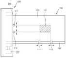
도 2a 및 도 2b는 도 1의 디스플레이 장치를 상부에서 바라본 것으로, 제1 위치 선택부 내지 제4 위치 선택부에 의해 디스플레이 영역이 선택되는 모습을 나타낸 것이다.
도 3은 본 개시의 디스플레이 장치에 있어서 활성화 영역이 선택되는 메카니즘의 일 예를 설명하기 위한 도면이다.
도 4는 본 개시의 디스플레이 장치에 있어서 활성화 영역이 선택되는 메카니즘의 다른 예을 설명하기 위한 도면이다.
도 5는 본 개시의 다른 실시예에 따른 디스플레이 장치를 개략적으로 도시한 평면도이다.1 is a perspective view schematically illustrating a display device according to an exemplary embodiment of the present disclosure.
2A and 2B are views of the display device of FIG. 1 from above, and show a display area selected by the first position selector to the fourth position selector.
3 is a view for explaining an example of a mechanism in which an activation area is selected in the display device of the present disclosure.
4 is a view for explaining another example of a mechanism in which an activation area is selected in the display device of the present disclosure.
5 is a plan view schematically illustrating a display device according to another exemplary embodiment of the present disclosure.
이하, 첨부된 도면을 참조하여 본 개시에 따른 실시예들을 상세히 설명한다.도면에서 동일한 참조부호는 동일한 구성요소를 지칭하며, 이들에 대한 중복된 설명은 생략한다. 또한, 각 구성요소의 크기는 설명의 명료성과 편의상 과장되어 있을 수 있다.DETAILED DESCRIPTION Hereinafter, exemplary embodiments of the present disclosure will be described in detail with reference to the accompanying drawings. Like reference numerals in the drawings denote like elements, and repeated descriptions thereof will be omitted. In addition, the size of each component may be exaggerated for clarity and convenience of description.
한편, 이하에 설명되는 실시예는 단지 예시적인 것에 불과하며, 이러한 실시예들로부터 다양한 변형이 가능하다.Meanwhile, the embodiments described below are merely exemplary, and various modifications are possible from these embodiments.
또한, 본 명세서에서 사용된 용어는 실시예들을 설명하기 위한 것이며 본 발명을 제한하고자 하는 것은 아니다. 본 명세서에서, 단수형은 문구에서 특별히 언급하지 않는 한 복수형도 포함한다. 명세서에서 사용되는 "포함한다" 및/또는 "포함하는"은 언급된 구성요소, 단계, 동작 및/또는 소자의 존재 또는 추가를 배제하지 않는다. 제1, 제2 등의 용어는 다양한 구성요소들을 설명하는데 사용될 수 있지만, 구성요소들은 용어들에 의해 한정되어서는 안 된다. 용어들은 하나의 구성요소를 다른 구성요소로부터 구별하는 목적으로만 사용된다.Also, the terminology used herein is for the purpose of describing particular embodiments only and is not intended to be limiting of the invention. In this specification, the singular also includes the plural unless specifically stated otherwise in the phrase. As used herein, “comprises” and / or “comprising” does not exclude the presence or addition of the components, steps, operations, and / or elements mentioned. Terms such as first and second may be used to describe various components, but the components should not be limited by the terms. The terms are only used to distinguish one component from another.
도 1은 본 개시의 일 실시예에 따른 디스플레이 장치(10)를 개략적으로 도시한 사시도이다. 도 2a 및 도 2b는 도 1의 디스플레이 장치(10)를 상부에서 바라본 것으로, 디스플레이 패널의 활성화 영역이 정해지는 모습을 나타낸 것이다.1 is a schematic perspective view of a
도 1 내지 도 2b를 참조하면, 디스플레이 장치(10)는 디스플레이 패널(100), 원통형 지그(200), 하우징(housing, 300)을 포함할 수 있다.1 to 2B, the
디스플레이 패널(100)은 디스플레이 장치에서 처리되는 화상을 표시한다. 일례로, 디스플레이 장치가 휴대용 컴퓨터일 경우, 이와 관련된 UI(user interface) 또는 GUI(Graphic User Interface) 등의 화상을 표시할 수 있다.The
디스플레이 패널(100)은 디스플레이 패널(100)의 일 모서리에 제1 방향(도면에서, X축 방향)으로 나란히 배치되는 제1 위치 선택부(111) 및 제2 위치 선택부(112)를 구비한다. 그리고, 디스플레이 패널(100)은 디스플레이 패널(100)의 상부에 제2 방향(도면에서, Y축 방향)으로 나란히 배치되는 제3 위치 선택부(311) 및 제4 위치 선택부(312)를 구비한다.The
제1 위치 선택부(111), 제2 위치 선택부(112), 제3 위치 선택부(311), 및 제4 위치 선택부(312)는 디스플레이 패널(100)에서 활성화 영역(101) 및 비활성화 영역(103)을 정하기 위해 구비된 것일 수 있다. 활성화 영역(101)은 디스플레이 패널(100)이 턴-온(turn-on)되는 영역으로 정의될 수 있으며, 비활성화 영역(103)은 디스플레이 패널(100)이 턴-오프(turn-off)되는 영역으로 정의될 수 있다. 그러나, 이에 한정되지 않고, 활성화 영역(101)은 디스플레이 패널의 밝기가 비활성화 영역(103) 보다 밝은 영역으로 정의될 수도 있다.The
제1 위치 선택부(111) 및 제2 위치 선택부(112)는 제1 방향(X축) 또는 제1 방향의 반대방향으로 이동이 가능하며, 제3 위치 선택부(311) 및 제4 위치 선택부(312)는 제2 방향(Y축) 또는 제2 방향의 반대방향으로 이동이 가능하다.The
제1 위치 선택부(111) 및 제2 위치 선택부(112)의 이동을 가이드 하기 위해서, 디스플레이 패널(100)의 일 모서리에는 제1 이동부(110)가 구비될 수 있다. 또한, 제3 위치 선택부(311) 및 제4 위치 선택부(312)의 이동을 가이드 하기 위해서, 하우징(300)의 일 측면에 제2 이동부(310)가 구비될 수 있다.In order to guide the movement of the
제1 위치 선택부(111) 및 제2 위치 선택부(112)에 의해서 활성화 영역(101)의 제1 방향(X축)으로의 길이가 정해질 수 있으며, 제3 위치 선택부(311) 및 제4 위치 선택부(312)에 의해서 활성화 영역(101)의 제2 방향(Y축)으로의 길이가 정해질 수 있다. 이에 따라, 도2a 및 도 2b와 같이 제1 내지 제4 위치 선택부(111, 112, 311, 312)의 위치를 조정하여 활성화 영역의 면적을 조절할 수 있게 된다.The length of the
이는 디스플레이 패널(100)이 복수의 센싱 라인(sensing line, 121, 122, 도 3 참조)을 구비하는 것으로 구현될 수 있다. 즉, 디스플레이 패널(100)은 복수의 제1 방향(X축)으로 연장되는 복수의 제1 센싱 라인(121, 도 3 참조) 및 제2 방향(Y축)으로 연장되는 복수의 제2 센싱 라인(122, 도 3 참조)을 포함할 수 있다.This may be implemented by the
따라서, 상기 제1 위치 선택부(111), 제2 위치 선택부(112), 제3 위치 선택부(311), 및 제4 위치 선택부(312)와 상기 복수의 센싱 라인(121, 122)과의 상호 작용에 의해서 활성화 영역을 정할 수 있다. 활성화 영역을 결정하는 보다 자세한 메카니즘에 대해서는 도 3 및 도 4를 참조하여 설명하도록 한다.Accordingly, the
일부 실시예에서, 복수의 제1 센싱 라인(121) 및 복수의 제2 센싱 라인(122)은 정전용량의 변화를 감지하는 센서일 수 있다. 이 경우, 제1 위치 선택부(111), 제2 위치 선택부(112), 제3 위치 선택부(311), 및 제4 위치 선택부(312)가 복수의 센싱 라인(121, 122)의 상부에 배치되는 경우, 정전용량의 변화가 발생하게 되어 각 위치 선택부(111, 112, 311, 314)의 위치를 감지할 수 있게 된다.In some embodiments, the plurality of
일부 실시예에서, 복수의 제1 센싱 라인(121) 및 복수의 제2 센싱 라인(122)은 압력의 변화를 감지하는 센서일 수 있다. 이 경우, 제1 위치 선택부(111), 제2 위치 선택부(112), 제3 위치 선택부(311), 및 제4 위치 선택부(312)가 복수의 센싱 라인(121, 122)에 압력을 가하는 경우, 압력의 변화를 발생하게 되어 각 위치 선택부(111, 112, 311, 314)의 위치를 감지할 수 있게 된다.In some embodiments, the plurality of
일부 실시예에서, 제1 위치 선택부(111), 제2 위치 선택부(112), 제3 위치 선택부(311), 및 제4 위치 선택부(312)는 도전 물질을 포함할 수 있다. 일부 실시예에서, 제1 위치 선택부(111), 제2 위치 선택부(112), 제3 위치 선택부(311), 및 제4 위치 선택부(312)는 디스플레이 패널(100)의 표면에 접촉될 수 있다.In some embodiments, the
일부 실시예에서, 제1 위치 선택부(111) 및 제2 위치 선택부(112)는 "ㄷ"자 형상을 갖고, 디스플레이 패널(100)의 상하부면에 걸쳐 배치될 수 있다. 제1 위치 선택부(111) 및 제2 위치 선택부(112)는 제1 이동부(110)을 따라 지퍼(zipper)형식으로 이동될 수 있다. 이에 따라, 사용자가 조절하기 용이할 수 있다. 일부 실시예에서, 제3 위치 선택부(311) 및 제4 위치 선택부(312)는 원통의 형상을 가질 수 있다. In some embodiments, the
디스플레이 패널(100)은 복수의 액정 또는 복수의 유기발광소자를 포함할 수 있다. 디스플레이 패널(100)은 플렉서블(flexible)한 패널일 수 있으며, 돌돌 감아 말 수 있는 롤러블(rollable) 패널일 수 있다. 디스플레이 패널(100)은 투명형 또는 광투과형으로 구성될 수 있다.The
디스플레이 패널(100)의 상면에는 상기 복수의 센싱 라인(121, 122)과는 별도로 터치 필름, 터치 시트, 터치 패드 등의 형태를 가지고 터치 동작을 감지하는 터치 센서가 위치할 수 있다. 그러나 이에 한정되지 않고, 상기 복수의 센싱 라인(121, 122)가 활성화 영역 내부에서의 터치 동작에 대해서도 감지할 수 있다. 디스플레이 패널(100)은 제어부(미도시) 연결되어 있으며, 제어부(미도시)로부터 전송된 신호에 의해 화상을 표시할 수 있다.A touch sensor that detects a touch operation in the form of a touch film, a touch sheet, a touch pad, etc. may be positioned on the upper surface of the
디스플레이 패널(100)은 플렉서블 배터리(미도시)를 더 포함할 수 있다. 플렉서블 배터리는 초박형 구조로 제조되어 돌돌 말릴 수 있는 가요성 내지 유연성을 가질 수 있다. 그러나, 이에 한정되지 않고, 디스플레이 패널(100)은 플렉서블 배터리를 포함하지 않고, 별도의 전원 공급기에 의해서 전원이 공급될 수도 있다.The
원통형 지그(200)는 상술한 디스플레이 패널(100)이 감겨지는 것으로, 롤러블 디스플레이 패널(100)이 원통형 지그(200)에 감겨서 보관될 수 있어서 롤러블 디스플레이 장치는 소형화가 가능하고 휴대가 용이할 수 있다. 원통형 지그(200)는 하우징(300) 내부에 탑재되어 원통의 중심을 축으로 회전이 가능하게 배치될 수 있다. 하우징(300) 내부에는 원통형 지그(200)가 하우징(300)과 연결되어 원통의 중심을 축으로 하여 회전할 수 있도록 내부 연결부재(미도시)가 더 포함될 수 있다. 또한, 원통형 지그(200)는 외부에서 회전할 수 있도록 외부 조작부(미도시)와 연결될 수 있다.The
하우징(300)은 디스플레이 패널(100)이 감겨져 있는 원통형 지그(200)를 포장하는 것으로 상기 디스플레이 패널(100)을 외부로부터 보호하는 역할을 할 수 있다.The
상기 하우징(300)의 일면에는 디스플레이 패널(100)의 일부가 외부로 나올 수 있는 홀(hole, 301)이 마련된다. 상기 홀(301)을 통하여 디스플레이 패널(100)의 일부가 펼쳐져 나올 수 있다. 또한, 상술한 바와 같이, 하우징(300)의 일면에는 상기 제3 위치 선택부(311) 및 상기 제4 위치 선택부(312)가 이동할 수 있는 제2 이동부(310)가 구비될 수 있다. 제2 이동부(310)는 제3 위치 선택부(311) 및 제4 위치 선택부(312)의 상하 방향으로의 위치를 조절할 수 있는 기능이 포함되어 있을 수 있다. 이에 따라, 제3 위치 선택부(311) 및 제4 위치 선택부(312)는 디스플레이 패널(100)과 접촉 또는 근접할 수 있게 조절될 수 있다.One surface of the
상술한 디스플레이 장치(10)는 제1 위치 선택부(111), 제2 위치 선택부(112), 제3 위치 선택부(311), 및 제4 위치 선택부(312)에 의해서 디스플레이 패널(100)의 활성화 영역(101)을 정할 수 있다. 이에 따라, 사용자가 원하는 디스플레이 영역만 턴-온(turn-on)될 수 있어, 디스플레이 장치(10)의 소비 전력을 줄일 수 있다.The
도 3은 본 개시의 디스플레이 장치에 있어서 활성화 영역이 선택되는 메카니즘의 일 예를 설명하기 위한 도면이다.3 is a view for explaining an example of a mechanism in which an activation area is selected in the display device of the present disclosure.
도 3을 참조하면, 디스플레이 패널(100)은 제1 방향(X축)으로 연장되는 복수의 제1 센싱 라인(121) 및 제2 방향(Y축)으로 연장되는 복수의 제2 센싱 라인(122)을 포함한다. 복수의 제1 센싱 라인(121)은 제2 방향(Y축)으로 나란히 배열될 수 있으며, 복수의 제2 센싱 라인(122)는 제1 방향(X축)으로 나란히 배열될 수 있다.Referring to FIG. 3, the
제1 위치 선택부(111) 및 제2 위치 선택부(112)는 각각 복수의 제2 센싱 라인(122) 중 어느 하나를 선택하여 디스플레이 패널(100)의 제1 방향(X축)으로의 좌표인 Xa 및 Xb를 정할 수 있다.Each of the
도면에서, 복수의 제2 센싱 라인(122)은 제1 방향(X축)으로 나란히 배열되어 디스플레이 패널(100)의 제1 방향(X축)으로의 좌표인 X0, X1, X2, X3,…를 나타낼 수 있다. 제1 위치 선택부(111)는 상기 복수의 제2 센싱 라인(122) 중 X1의 좌표를 나타내는 센싱 라인을 선택할 수 있다. 이 경우, Xa는 X1이 된다. 제2 위치 선택부(112)는 상기 복수의 제2 센싱 라인(122) 중 X3의 좌표를 나타내는 센싱 라인을 선택할 수 있다. 이 경우, Xb는 X3가 된다.In the drawing, the plurality of
한편, 제3 위치 선택부(311) 및 제4 위치 선택부(312)는 각각 복수의 제1 센싱 라인(121) 중 어느 하나를 선택하여 디스플레이 패널(100)의 제2 방향(Y축)으로의 좌표인 Ya 및 Yb를 정할 수 있다.Meanwhile, the
복수의 제1 센싱 라인(121)은 제2 방향(Y축)으로 나란히 배열되어 디스플레이 패널(100)의 제2 방향(Y축)으로의 좌표인 Y0, Y1, Y2, Y3,…를 나타낼 수 있다. 제3 위치 선택부(311)는 상기 복수의 제1 센싱 라인(121) 중 Y1의 좌표를 나타내는 센싱 라인을 선택할 수 있다. 이 경우, Ya는 Y1이 된다. 제4 위치 선택부(312)는 상기 복수의 제1 센싱 라인(121) 중 Y3의 좌표를 나타내는 센싱 라인을 선택할 수 있다. 이 경우, Yb는 Y3가 된다.The plurality of
이와 같이, 제1 내지 제4 위치 선택부(111, 112, 311, 312)에 의해서 선택된 좌표들이 만나서 이루는 네 개의 좌표, 즉, (Xa, Ya), (Xa, Yb), (Xb, Ya), (Xb, Yb)를 이어서 만든 폐곡선 내부의 영역을 활성화 영역(101)으로 정할 수 있다.As such, four coordinates formed by meeting coordinates selected by the first to fourth
도면에서는 (X1, Y1), (X1, Y3), (X3, Y1), (X3, Y3)을 이어서 만든 폐곡선의 내부 영역이 활성화 영역(101)이 된다. In the drawing, the inner region of the closed curve made of (X1, Y1), (X1, Y3), (X3, Y1), and (X3, Y3) subsequently becomes the
도 4는 본 개시의 디스플레이 장치에 있어서 활성화 영역이 선택되는 메카니즘의 다른 예을 설명하기 위한 도면이다. 도 4에 있어서, 도 3에서와 동일한 참조 부호는 동일 부재를 나타내며, 여기서는 설명의 간략화를 위하여 이들의 중복 설명은 생략한다.4 is a view for explaining another example of a mechanism in which an activation area is selected in the display device of the present disclosure. In Fig. 4, the same reference numerals as those in Fig. 3 denote the same members, and redundant description thereof is omitted here for the sake of simplicity.
도 4를 참조하면, 제1 내지 제4 위치 선택부(111, 112, 311, 312)가 여러 개의 센싱 라인에 걸쳐있는 경우를 나타낸다. 이 경우, 활성화 영역(101)을 정하는 방식은 다양할 수 있다.Referring to FIG. 4, the first to fourth
예를 들어, 제1 위치 선택부(111) 및 제2 위치 선택부(112)가 두 개 이상의 제2 센싱 라인(122)에 걸쳐있는 경우, X 좌표를 정함에 있어, 그 중 가장 큰 좌표를 활성화 영역을 정하는 X 좌표로 정할 수 있다. 즉, 도면에서, 제1 위치 선택부(111)는 X2 및 X3를 나타내는 센싱 라인에 걸쳐 있지만, 활성화 영역이 되는 Xa 좌표는 X2보다 큰 좌표인 X3를 선택할 수 있다. 또한, 제2 위치 선택부(112)는 X4 및 X5를 나타내는 센싱 라인에 걸쳐 있지만, 활성화 영역이 되는 Xb 좌표는 X4 보다 큰 좌표인 X5를 선택할 수 있다.For example, when the
마찬가지로, 제3 위치 선택부(311) 및 제4 위치 선택부(312)가 활성화 영역의 좌표로 선택하는 좌표는 제3 위치 선택부(311) 및 제4 위치 선택부(312)가 걸쳐져 있는 좌표 중 가장 큰 좌표로 선택하도록 정할 수 있다. 즉, 도면에서, Ya는 Y1이고 Yb는 Y4가 되도록 정할 수 있다.Similarly, the coordinates selected by the
이에 따라, 활성화 영역(101)은 (X3, Y1), (X3, Y4), (X5, Y1), (X5, Y4)로 이어지는 폐곡선 내부 영역이 될 수 있다. 활성화 영역(101)의 좌표를 정하는 것은 이에 한정되지 않으며, 다양한 변형이 가능하다.Accordingly, the
도 5는 본 개시의 다른 실시예에 따른 디스플레이 장치(20)를 개략적으로 도시한 평면도이다. 도 5에 있어서, 도 1에서와 동일한 참조 부호는 동일 부재를 나타내며, 여기서는 설명의 간략화를 위하여 이들의 중복 설명은 생략한다.5 is a plan view schematically illustrating a
도 5에 있어서, 디스플레이 장치(20)는 도 1의 디스플레이 장치(10)와 비교할 때, 추가 하우징(500) 및 추가 원통형 지그(400)이 더 포함되어 있다는 점에서 차이가 있다.In FIG. 5, the
디스플레이 장치(20)는 디스플레이 패널(100)의 일측에 하우징(300)이 있으며, 다른 일측에는 추가 하우징(500)이 있다. 추가 하우징(500)은 디스플레이 패널(100)을 감아 놓을 때, 보호하는 역할을 할 수 있으며, 디스플레이 패널을 펼치 때 용이하게 펼칠 수 있는 역할을 할 수 있다. 추가 하우징(500)에는 디스플레이 패널의 일부가 외부로 나올 수 있는 홀(미도시)이 구비된다.The
추가 하우징(500) 내부에는 추가 원통형 지그(400)이 마련된다. 추가 원통형 지그(400)에는 디스플레이 패널(100)이 감길 수 있다. 추가 하우징(500) 내부에는 추가 원통형 지그(400)가 추가 하우징(500)과 연결되어 원통의 중심을 축으로 하여 회전할 수 있도록 내부 연결부재(미도시)가 더 포함될 수 있다. 또한, 추가 원통형 지그(400)는 외부에서 회전할 수 있도록 외부 조작부(미도시)와 연결될 수도 있다.An additional
추가 하우징(500) 및 추가 원통형 지그(400)가 마련되어, 디스플레이 장치(20)는 디스플레이 패널(100)의 보호 및 휴대가 더 용이해 질 수 있다.The
본 개시의 실시예에 따른 디스플레이 장치(10, 20)는 이해를 돕기 위하여 도면에 도시된 실시예를 참고로 설명되었으나, 이는 예시적인 것에 불과하며, 당해 분야에서 통상적 지식을 가진 자라면 이로부터 다양한 변형 및 균등한 타 실시예가 가능하다는 점을 이해할 것이다.The display apparatuses 10 and 20 according to the exemplary embodiments of the present disclosure have been described with reference to the exemplary embodiments illustrated in the drawings for clarity of understanding, but these are merely exemplary, and those skilled in the art will appreciate It will be appreciated that variations and other equivalent embodiments are possible.
10, 20: 디스플레이 장치
100: 디스플레이 패널
101: 활성화 영역103: 비활성화 영역
200: 원통형 지그300: 하우징
400: 추가 원통형 지그500: 추가 하우징
110: 제1 이동부310: 제2 이동부
111: 제1 위치 선택부112: 제2 위치 선택부
311: 제3 위치 선택부312: 제4 위치 선택부
121: 제1 센싱 라인
122: 제2 센싱 라인
21, 122: 복수의 센싱 라인10, 20: display device
100: display panel
101: active area 103: inactive area
200: cylindrical jig 300: housing
400: additional cylindrical jig 500: additional housing
110: first moving unit 310: second moving unit
111: first position selector 112: second position selector
311: third position selector 312: fourth position selector
121: first sensing line
122: second sensing line
21, 122: multiple sensing lines
Claims (22)
Translated fromKorean상기 디스플레이 패널의 일 모서리에 상기 제1 방향으로 나란히 배치되는 제1 위치 선택부 및 제2 위치 선택부; 및
상기 디스플레이 패널의 상부에 상기 제2 방향으로 나란히 배치되는 제3 위치 선택부 및 제4 위치 선택부;를 포함하고,
상기 제1 위치 선택부, 제2 위치 선택부, 제3 위치 선택부, 및 제4 위치 선택부에 의해서 상기 디스플레이 패널의 활성화 영역이 정해지며,
상기 복수의 제1 센싱 라인 및 상기 복수의 제2 센싱 라인은 정전용량의 변화를 감지하는 디스플레이 장치.A display panel including a plurality of first sensing lines extending in a first direction and a plurality of second sensing lines extending in a second direction;
A first position selector and a second position selector disposed side by side in the first direction on one edge of the display panel; And
And a third position selector and a fourth position selector disposed on the display panel side by side in the second direction.
An activation area of the display panel is determined by the first position selector, the second position selector, the third position selector, and the fourth position selector.
And a plurality of first sensing lines and the plurality of second sensing lines sense a change in capacitance.
상기 제1 위치 선택부 및 상기 제2 위치 선택부에 의해서 상기 활성화 영역의 제1 방향으로의 길이가 정해지는 디스플레이 장치.The method of claim 1,
And a length in the first direction of the active area is determined by the first position selector and the second position selector.
상기 제3 위치 선택부 및 상기 제4 위치 선택부에 의해서 상기 활성화 영역의 제2 방향으로의 길이가 정해지는 디스플레이 장치.The method of claim 1,
And a length in the second direction of the active area is determined by the third position selector and the fourth position selector.
상기 제1 위치 선택부 및 상기 제2 위치 선택부 각각은 상기 복수의 제2 센싱 라인 중 어느 하나를 선택하여 디스플레이 패널의 제1 방향으로의 좌표인 Xa 및 Xb를 정하고,
상기 제3 위치 선택부 및 상기 제4 위치 선택부 각각은 상기 복수의 제1 센싱 라인 중 어느 하나를 선택하여 디스플레이 패널의 제2 방향으로의 좌표인 Ya 및 Yb를 정하며,
상기 Xa, Xb, Ya, Yb가 만나서 이루는 네 개의 좌표인 (Xa, Ya), (Xa, Yb), (Xb, Ya), (Xb, Yb)를 이어서 만든 폐곡선 내부의 영역이 활성화 영역이 되는 디스플레이 장치.The method of claim 1,
Each of the first position selector and the second position selector selects one of the plurality of second sensing lines to determine Xa and Xb which are coordinates in a first direction of the display panel.
Each of the third position selector and the fourth position selector selects one of the plurality of first sensing lines to determine Ya and Yb, which are coordinates in a second direction of the display panel.
The area inside the closed curve which is made up of four coordinates (Xa, Ya), (Xa, Yb), (Xb, Ya), and (Xb, Yb) formed by the meeting of Xa, Xb, Ya, and Yb becomes an active area. Display device.
상기 제1 위치 선택부 및 상기 제2 위치 선택부는 제1 방향으로 이동이 가능하며,
상기 제3 위치 선택부 및 상기 제4 위치 선택부는 제2 방향으로 이동이 가능한 디스플레이 장치.The method of claim 1,
The first position selector and the second position selector are movable in a first direction,
And the third position selector and the fourth position selector are movable in a second direction.
상기 디스플레이 패널은 플렉서블(flexible)한 디스플레이 장치.The method of claim 1,
The display panel is a flexible display device.
상기 제1 방향과 제2 방향은 수직을 이루는 디스플레이 장치.The method of claim 1,
The display device is perpendicular to the first direction and the second direction.
상기 제1 위치 선택부, 상기 제2 위치 선택부, 제3 위치 선택부, 및 제4 위치 선택부는 도전 물질을 포함하는 디스플레이 장치.The method of claim 1,
The first position selector, the second position selector, the third position selector, and the fourth position selector include a conductive material.
상기 디스플레이 패널의 일 모서리에는 상기 제1 위치 선택부 및 상기 제2 위치 선택부가 상기 제1 방향으로 이동할 수 있도록 가이드하는 제1 이동부가 구비된 디스플레이 장치.The method of claim 1,
And a first moving part disposed at one corner of the display panel to guide the first position selecting part and the second position selecting part to move in the first direction.
상기 디스플레이 패널의 일 모서리에 상기 제1 방향으로 나란히 배치되는 제1 위치 선택부 및 제2 위치 선택부;
상기 디스플레이 패널의 상부에 상기 제2 방향으로 나란히 배치되는 제3 위치 선택부 및 제4 위치 선택부;
상기 디스플레이 패널이 감겨지는 원통형 지그; 및
상기 원통형 지그가 탑재되고 상기 디스플레이 패널이 외부로 나올 수 있는 홀(hole)을 구비하는 하우징(housing);을 포함하고,
상기 제1 위치 선택부, 제2 위치 선택부, 제3 위치 선택부, 및 제4 위치 선택부에 의해서 상기 디스플레이 패널의 활성화 영역이 정해지며,
상기 복수의 제1 센싱 라인 및 상기 복수의 제2 센싱 라인은 정전용량의 변화를 감지하는 디스플레이 장치.A display panel including a plurality of first sensing lines extending in a first direction and a plurality of second sensing lines extending in a second direction;
A first position selector and a second position selector disposed side by side in the first direction on one edge of the display panel;
A third position selector and a fourth position selector disposed on the display panel side by side in the second direction;
A cylindrical jig in which the display panel is wound; And
And a housing in which the cylindrical jig is mounted and having a hole through which the display panel can come out.
An activation area of the display panel is determined by the first position selector, the second position selector, the third position selector, and the fourth position selector.
And a plurality of first sensing lines and the plurality of second sensing lines sense a change in capacitance.
상기 하우징에는 상기 제3 위치 선택부 및 제4 위치 선택부가 상기 제2 방향으로 이동할 수 있도록 가이드하는 제2 이동부가 구비된 디스플레이 장치.The method of claim 11,
And a second moving part configured to guide the third position selector and the fourth position selector to move in the second direction.
상기 제1 위치 선택부 및 상기 제2 위치 선택부에 의해서 상기 활성화 영역의 제1 방향으로의 길이가 정해지는 디스플레이 장치.The method of claim 11,
And a length in the first direction of the active area is determined by the first position selector and the second position selector.
상기 제3 위치 선택부 및 상기 제4 위치 선택부에 의해서 상기 활성화 영역의 제2 방향으로의 길이가 정해지는 디스플레이 장치.The method of claim 11,
And a length in the second direction of the active area is determined by the third position selector and the fourth position selector.
상기 제1 위치 선택부 및 상기 제2 위치 선택부 각각은 상기 복수의 제2 센싱 라인 중 어느 하나를 선택하여 디스플레이 패널의 제1 방향으로의 좌표인 Xa 및 Xb를 정하고,
상기 제3 위치 선택부 및 상기 제4 위치 선택부 각각은 상기 복수의 제1 센싱 라인 중 어느 하나를 선택하여 디스플레이 패널의 제2 방향으로의 좌표인 Ya 및 Yb를 정하며,
상기 Xa, Xb, Ya, Yb가 만나서 이루는 네 개의 좌표인 (Xa, Ya), (Xa, Yb), (Xb, Ya), (Xb, Yb)를 이어서 만든 폐곡선 내부의 영역이 활성화 영역이 되는 디스플레이 장치.The method of claim 11,
Each of the first position selector and the second position selector selects one of the plurality of second sensing lines to determine Xa and Xb which are coordinates in a first direction of the display panel.
Each of the third position selector and the fourth position selector selects one of the plurality of first sensing lines to determine Ya and Yb, which are coordinates in a second direction of the display panel.
The area inside the closed curve which is made up of four coordinates (Xa, Ya), (Xa, Yb), (Xb, Ya), and (Xb, Yb) formed by the meeting of Xa, Xb, Ya, and Yb becomes an active area. Display device.
상기 제1 위치 선택부 및 상기 제2 위치 선택부는 제1 방향으로 이동이 가능하며,
상기 제3 위치 선택부 및 상기 제4 위치 선택부는 제2 방향으로 이동이 가능한 디스플레이 장치.The method of claim 11,
The first position selector and the second position selector are movable in a first direction,
And the third position selector and the fourth position selector are movable in a second direction.
상기 제1 방향과 제2 방향은 수직을 이루는 디스플레이 장치.The method of claim 11,
The display device is perpendicular to the first direction and the second direction.
상기 제1 위치 선택부, 상기 제2 위치 선택부, 제3 위치 선택부, 및 제4 위치 선택부는 도전 물질을 포함하는 디스플레이 장치.The method of claim 11,
The first position selector, the second position selector, the third position selector, and the fourth position selector include a conductive material.
상기 디스플레이 패널의 일 모서리에는 상기 제1 위치 선택부 및 상기 제2 위치 선택부가 상기 제1 방향으로 이동할 수 있도록 가이드하는 제1 이동부가 구비된 디스플레이 장치.The method of claim 11,
And a first moving part disposed at one corner of the display panel to guide the first position selecting part and the second position selecting part to move in the first direction.
상기 제1 위치 선택부 및 상기 제2 위치 선택부는 'ㄷ'자 형상을 가지며, 상기 디스플레이 패널의 상하부에 걸쳐지는 디스플레이 장치.The method of claim 11,
The first position selection unit and the second position selection unit has a '-' shape, and the display device spanning the upper and lower portions of the display panel.
상기 제3 위치 선택부 및 상기 제4 위치 선택부는 원통 형상을 가지는 디스플레이 장치.
The method of claim 11,
And the third position selector and the fourth position selector have a cylindrical shape.
Priority Applications (2)
| Application Number | Priority Date | Filing Date | Title |
|---|---|---|---|
| KR1020130035956AKR102069191B1 (en) | 2013-04-02 | 2013-04-02 | Power-saving display device |
| US13/942,424US9013431B2 (en) | 2013-04-02 | 2013-07-15 | Power-saving display device |
Applications Claiming Priority (1)
| Application Number | Priority Date | Filing Date | Title |
|---|---|---|---|
| KR1020130035956AKR102069191B1 (en) | 2013-04-02 | 2013-04-02 | Power-saving display device |
Publications (2)
| Publication Number | Publication Date |
|---|---|
| KR20140120183A KR20140120183A (en) | 2014-10-13 |
| KR102069191B1true KR102069191B1 (en) | 2020-01-23 |
Family
ID=51620295
Family Applications (1)
| Application Number | Title | Priority Date | Filing Date |
|---|---|---|---|
| KR1020130035956AActiveKR102069191B1 (en) | 2013-04-02 | 2013-04-02 | Power-saving display device |
Country Status (2)
| Country | Link |
|---|---|
| US (1) | US9013431B2 (en) |
| KR (1) | KR102069191B1 (en) |
Cited By (1)
| Publication number | Priority date | Publication date | Assignee | Title |
|---|---|---|---|---|
| WO2022103014A1 (en)* | 2020-11-13 | 2022-05-19 | 삼성전자 주식회사 | Electrode device including flexible display, and display method using same |
Families Citing this family (10)
| Publication number | Priority date | Publication date | Assignee | Title |
|---|---|---|---|---|
| KR102326034B1 (en)* | 2014-11-17 | 2021-11-16 | 삼성디스플레이 주식회사 | Display appratus |
| KR102304310B1 (en)* | 2015-02-13 | 2021-09-23 | 삼성디스플레이 주식회사 | Rollable display device |
| CN104851366B (en)* | 2015-05-29 | 2018-02-06 | 京东方科技集团股份有限公司 | A kind of flexible display apparatus |
| USD836077S1 (en)* | 2015-08-31 | 2018-12-18 | Lg Electronics Inc. | Mobile phone |
| DE102015015630A1 (en) | 2015-12-03 | 2017-06-08 | Audi Ag | Device for mounting in a motor vehicle, motor vehicle with a device and method for operating a device |
| KR102468289B1 (en)* | 2016-05-30 | 2022-11-17 | 엘지디스플레이 주식회사 | Rollable display device |
| KR102527213B1 (en)* | 2016-07-05 | 2023-04-28 | 삼성디스플레이 주식회사 | Display device |
| KR102691770B1 (en)* | 2016-09-20 | 2024-08-05 | 삼성디스플레이 주식회사 | Flexible display device |
| CN110010009B (en)* | 2019-04-28 | 2021-04-20 | 武汉天马微电子有限公司 | Rollable display device |
| KR20220036419A (en)* | 2020-09-14 | 2022-03-23 | 삼성디스플레이 주식회사 | Display device |
Citations (1)
| Publication number | Priority date | Publication date | Assignee | Title |
|---|---|---|---|---|
| JP2005099872A (en)* | 2004-12-20 | 2005-04-14 | Seiko Epson Corp | Liquid crystal display device, display device and electronic apparatus |
Family Cites Families (19)
| Publication number | Priority date | Publication date | Assignee | Title |
|---|---|---|---|---|
| US8479122B2 (en)* | 2004-07-30 | 2013-07-02 | Apple Inc. | Gestures for touch sensitive input devices |
| JP2003162370A (en)* | 2001-09-14 | 2003-06-06 | Ricoh Co Ltd | Image processing apparatus, display device with touch panel, image processing method, and program for causing computer to execute image processing method |
| JP3999688B2 (en) | 2003-03-12 | 2007-10-31 | 日本電信電話株式会社 | Screen display method, screen display device, screen display program, and recording medium on which screen display program is recorded |
| JPWO2004084171A1 (en)* | 2003-03-19 | 2006-06-22 | 松下電器産業株式会社 | Display device |
| EP1960828A2 (en)* | 2005-12-16 | 2008-08-27 | Polymer Vision Limited | Circular displays |
| WO2007145518A1 (en)* | 2006-06-14 | 2007-12-21 | Polymer Vision Limited | User input on rollable display device |
| CN101681038B (en)* | 2006-10-19 | 2011-10-19 | 创造者科技有限公司 | Front lighting for rollable or wrappable display devices |
| EP1967937A1 (en)* | 2007-03-06 | 2008-09-10 | Polymer Vision Limited | A display unit, a method and a computer program product |
| EP1970799B1 (en)* | 2007-03-15 | 2017-08-16 | LG Electronics Inc. | Electronic device and method of controlling mode thereof and mobile communication terminal |
| JP5045590B2 (en)* | 2008-07-23 | 2012-10-10 | 三菱電機株式会社 | Display device |
| KR100998076B1 (en) | 2008-09-24 | 2010-12-03 | 주식회사 오비고 | Image size adjusting device and method of information terminal |
| US20100088653A1 (en)* | 2008-10-07 | 2010-04-08 | Research In Motion Limited | Portable electronic device and method of controlling same |
| KR20120013807A (en)* | 2010-08-06 | 2012-02-15 | 엘지전자 주식회사 | Mobile terminal providing lighting and highlight function and control method thereof |
| KR101227644B1 (en) | 2010-08-10 | 2013-01-30 | 유상규 | Rollable flexible display device |
| JP5714935B2 (en)* | 2011-02-24 | 2015-05-07 | 京セラ株式会社 | Portable electronic device, contact operation control method, and contact operation control program |
| US10296205B2 (en)* | 2011-12-12 | 2019-05-21 | Sony Corporation | User interface for controlling a display scale of an image |
| JP5704408B2 (en)* | 2012-01-20 | 2015-04-22 | アイシン・エィ・ダブリュ株式会社 | Operation input system |
| US20130222416A1 (en)* | 2012-02-29 | 2013-08-29 | Pantech Co., Ltd. | Apparatus and method for providing a user interface using flexible display |
| TWI475436B (en)* | 2012-07-11 | 2015-03-01 | Wistron Corp | Frame with sensing function and touch control processing method |
- 2013
- 2013-04-02KRKR1020130035956Apatent/KR102069191B1/enactiveActive
- 2013-07-15USUS13/942,424patent/US9013431B2/enactiveActive
Patent Citations (1)
| Publication number | Priority date | Publication date | Assignee | Title |
|---|---|---|---|---|
| JP2005099872A (en)* | 2004-12-20 | 2005-04-14 | Seiko Epson Corp | Liquid crystal display device, display device and electronic apparatus |
Cited By (2)
| Publication number | Priority date | Publication date | Assignee | Title |
|---|---|---|---|---|
| WO2022103014A1 (en)* | 2020-11-13 | 2022-05-19 | 삼성전자 주식회사 | Electrode device including flexible display, and display method using same |
| US12169606B2 (en) | 2020-11-13 | 2024-12-17 | Samsung Electronics Co., Ltd. | Electronic device including flexible display, and display method using same |
Also Published As
| Publication number | Publication date |
|---|---|
| KR20140120183A (en) | 2014-10-13 |
| US20140292672A1 (en) | 2014-10-02 |
| US9013431B2 (en) | 2015-04-21 |
Similar Documents
| Publication | Publication Date | Title |
|---|---|---|
| KR102069191B1 (en) | Power-saving display device | |
| US10209878B2 (en) | Display apparatus | |
| KR102131825B1 (en) | Foldable display device providing adaptive touch sensitive region and method for controlling the same | |
| KR102375469B1 (en) | Flexible display apparatus | |
| KR101752750B1 (en) | Display device having expandable display, controlling method thereof and recording medium for performing the method | |
| US9983628B2 (en) | Flexible apparatus and control method thereof | |
| US20150277585A1 (en) | Dual display apparatus and method of driving the same | |
| CN104272219B (en) | Deformable display device and method for controlling a deformable display device | |
| KR102117526B1 (en) | Display system, flexible remote controller, flexible display apparatus and control methods thereof | |
| KR102278508B1 (en) | Stretchable display device | |
| CN104220963B (en) | Flexible display device and method of operating the same | |
| KR20140036846A (en) | User terminal device for providing local feedback and method thereof | |
| JP2015148799A (en) | Flexible display device | |
| JP2013225052A (en) | Display device | |
| CN104823134A (en) | Flexible display apparatus and flexible display apparatus controlling method | |
| CN103297605A (en) | Display method and electronic equipment | |
| US20190114044A1 (en) | Touch input method through edge screen, and electronic device | |
| KR20150096952A (en) | Display device and method for controlling the same | |
| KR20180025386A (en) | Electronic device and operating method of the same | |
| US20110084985A1 (en) | Input apparatus, display apparatus having an input function, input method, and method of controlling a display apparatus having an input function | |
| US20180011561A1 (en) | Information processing apparatus, input apparatus, method of controlling information processing apparatus, method of controlling input apparatus, and program | |
| KR20150024139A (en) | Display apparatus and control method thereof | |
| JP2017130158A (en) | Information processing apparatus, display method thereof, and computer-executable program | |
| KR102181887B1 (en) | Portable device | |
| EP2889730B1 (en) | Display device, electronic apparatus, and illumination region control method of display device |
Legal Events
| Date | Code | Title | Description |
|---|---|---|---|
| PA0109 | Patent application | Patent event code:PA01091R01D Comment text:Patent Application Patent event date:20130402 | |
| PG1501 | Laying open of application | ||
| PA0201 | Request for examination | Patent event code:PA02012R01D Patent event date:20180330 Comment text:Request for Examination of Application Patent event code:PA02011R01I Patent event date:20130402 Comment text:Patent Application | |
| E902 | Notification of reason for refusal | ||
| PE0902 | Notice of grounds for rejection | Comment text:Notification of reason for refusal Patent event date:20190331 Patent event code:PE09021S01D | |
| E701 | Decision to grant or registration of patent right | ||
| PE0701 | Decision of registration | Patent event code:PE07011S01D Comment text:Decision to Grant Registration Patent event date:20191022 | |
| GRNT | Written decision to grant | ||
| PR0701 | Registration of establishment | Comment text:Registration of Establishment Patent event date:20200116 Patent event code:PR07011E01D | |
| PR1002 | Payment of registration fee | Payment date:20200117 End annual number:3 Start annual number:1 | |
| PG1601 | Publication of registration | ||
| PR1001 | Payment of annual fee | Payment date:20221226 Start annual number:4 End annual number:4 | |
| PR1001 | Payment of annual fee | Payment date:20241230 Start annual number:6 End annual number:6 |