KR102068720B1 - Co-rotating compressor - Google Patents
Co-rotating compressorDownload PDFInfo
- Publication number
- KR102068720B1 KR102068720B1KR1020190140273AKR20190140273AKR102068720B1KR 102068720 B1KR102068720 B1KR 102068720B1KR 1020190140273 AKR1020190140273 AKR 1020190140273AKR 20190140273 AKR20190140273 AKR 20190140273AKR 102068720 B1KR102068720 B1KR 102068720B1
- Authority
- KR
- South Korea
- Prior art keywords
- scroll member
- compressor
- bearing housing
- end plate
- suction
- Prior art date
- Legal status (The legal status is an assumption and is not a legal conclusion. Google has not performed a legal analysis and makes no representation as to the accuracy of the status listed.)
- Active
Links
- 230000006835compressionEffects0.000claimsabstractdescription118
- 238000007906compressionMethods0.000claimsabstractdescription118
- 239000012530fluidSubstances0.000claimsdescription224
- 239000000314lubricantSubstances0.000claimsdescription141
- 238000004891communicationMethods0.000claimsdescription52
- 238000007789sealingMethods0.000claimsdescription31
- 238000000034methodMethods0.000claimsdescription22
- 230000007246mechanismEffects0.000description66
- 230000008878couplingEffects0.000description10
- 238000010168coupling processMethods0.000description10
- 238000005859coupling reactionMethods0.000description10
- 230000000712assemblyEffects0.000description3
- 238000000429assemblyMethods0.000description3
- 230000000694effectsEffects0.000description3
- 230000006698inductionEffects0.000description3
- 239000000203mixtureSubstances0.000description3
- 150000001875compoundsChemical class0.000description2
- 230000007423decreaseEffects0.000description2
- 230000008569processEffects0.000description2
- 238000010792warmingMethods0.000description2
- 239000002131composite materialSubstances0.000description1
- 238000012937correctionMethods0.000description1
- 230000002950deficientEffects0.000description1
- 238000002347injectionMethods0.000description1
- 239000007924injectionSubstances0.000description1
- 230000001050lubricating effectEffects0.000description1
- 238000012986modificationMethods0.000description1
- 230000004048modificationEffects0.000description1
- 230000002000scavenging effectEffects0.000description1
- 238000003466weldingMethods0.000description1
Images


Classifications
- F—MECHANICAL ENGINEERING; LIGHTING; HEATING; WEAPONS; BLASTING
- F04—POSITIVE - DISPLACEMENT MACHINES FOR LIQUIDS; PUMPS FOR LIQUIDS OR ELASTIC FLUIDS
- F04C—ROTARY-PISTON, OR OSCILLATING-PISTON, POSITIVE-DISPLACEMENT MACHINES FOR LIQUIDS; ROTARY-PISTON, OR OSCILLATING-PISTON, POSITIVE-DISPLACEMENT PUMPS
- F04C18/00—Rotary-piston pumps specially adapted for elastic fluids
- F04C18/02—Rotary-piston pumps specially adapted for elastic fluids of arcuate-engagement type, i.e. with circular translatory movement of co-operating members, each member having the same number of teeth or tooth-equivalents
- F04C18/0207—Rotary-piston pumps specially adapted for elastic fluids of arcuate-engagement type, i.e. with circular translatory movement of co-operating members, each member having the same number of teeth or tooth-equivalents both members having co-operating elements in spiral form
- F04C18/023—Rotary-piston pumps specially adapted for elastic fluids of arcuate-engagement type, i.e. with circular translatory movement of co-operating members, each member having the same number of teeth or tooth-equivalents both members having co-operating elements in spiral form where both members are moving
- F—MECHANICAL ENGINEERING; LIGHTING; HEATING; WEAPONS; BLASTING
- F04—POSITIVE - DISPLACEMENT MACHINES FOR LIQUIDS; PUMPS FOR LIQUIDS OR ELASTIC FLUIDS
- F04C—ROTARY-PISTON, OR OSCILLATING-PISTON, POSITIVE-DISPLACEMENT MACHINES FOR LIQUIDS; ROTARY-PISTON, OR OSCILLATING-PISTON, POSITIVE-DISPLACEMENT PUMPS
- F04C18/00—Rotary-piston pumps specially adapted for elastic fluids
- F04C18/02—Rotary-piston pumps specially adapted for elastic fluids of arcuate-engagement type, i.e. with circular translatory movement of co-operating members, each member having the same number of teeth or tooth-equivalents
- F04C18/0207—Rotary-piston pumps specially adapted for elastic fluids of arcuate-engagement type, i.e. with circular translatory movement of co-operating members, each member having the same number of teeth or tooth-equivalents both members having co-operating elements in spiral form
- F04C18/0215—Rotary-piston pumps specially adapted for elastic fluids of arcuate-engagement type, i.e. with circular translatory movement of co-operating members, each member having the same number of teeth or tooth-equivalents both members having co-operating elements in spiral form where only one member is moving
- F—MECHANICAL ENGINEERING; LIGHTING; HEATING; WEAPONS; BLASTING
- F04—POSITIVE - DISPLACEMENT MACHINES FOR LIQUIDS; PUMPS FOR LIQUIDS OR ELASTIC FLUIDS
- F04C—ROTARY-PISTON, OR OSCILLATING-PISTON, POSITIVE-DISPLACEMENT MACHINES FOR LIQUIDS; ROTARY-PISTON, OR OSCILLATING-PISTON, POSITIVE-DISPLACEMENT PUMPS
- F04C18/00—Rotary-piston pumps specially adapted for elastic fluids
- F04C18/02—Rotary-piston pumps specially adapted for elastic fluids of arcuate-engagement type, i.e. with circular translatory movement of co-operating members, each member having the same number of teeth or tooth-equivalents
- F04C18/0207—Rotary-piston pumps specially adapted for elastic fluids of arcuate-engagement type, i.e. with circular translatory movement of co-operating members, each member having the same number of teeth or tooth-equivalents both members having co-operating elements in spiral form
- F04C18/023—Rotary-piston pumps specially adapted for elastic fluids of arcuate-engagement type, i.e. with circular translatory movement of co-operating members, each member having the same number of teeth or tooth-equivalents both members having co-operating elements in spiral form where both members are moving
- F04C18/0238—Rotary-piston pumps specially adapted for elastic fluids of arcuate-engagement type, i.e. with circular translatory movement of co-operating members, each member having the same number of teeth or tooth-equivalents both members having co-operating elements in spiral form where both members are moving with symmetrical double wraps
- F—MECHANICAL ENGINEERING; LIGHTING; HEATING; WEAPONS; BLASTING
- F04—POSITIVE - DISPLACEMENT MACHINES FOR LIQUIDS; PUMPS FOR LIQUIDS OR ELASTIC FLUIDS
- F04C—ROTARY-PISTON, OR OSCILLATING-PISTON, POSITIVE-DISPLACEMENT MACHINES FOR LIQUIDS; ROTARY-PISTON, OR OSCILLATING-PISTON, POSITIVE-DISPLACEMENT PUMPS
- F04C18/00—Rotary-piston pumps specially adapted for elastic fluids
- F04C18/02—Rotary-piston pumps specially adapted for elastic fluids of arcuate-engagement type, i.e. with circular translatory movement of co-operating members, each member having the same number of teeth or tooth-equivalents
- F04C18/0207—Rotary-piston pumps specially adapted for elastic fluids of arcuate-engagement type, i.e. with circular translatory movement of co-operating members, each member having the same number of teeth or tooth-equivalents both members having co-operating elements in spiral form
- F04C18/0215—Rotary-piston pumps specially adapted for elastic fluids of arcuate-engagement type, i.e. with circular translatory movement of co-operating members, each member having the same number of teeth or tooth-equivalents both members having co-operating elements in spiral form where only one member is moving
- F04C18/0223—Rotary-piston pumps specially adapted for elastic fluids of arcuate-engagement type, i.e. with circular translatory movement of co-operating members, each member having the same number of teeth or tooth-equivalents both members having co-operating elements in spiral form where only one member is moving with symmetrical double wraps
- F—MECHANICAL ENGINEERING; LIGHTING; HEATING; WEAPONS; BLASTING
- F04—POSITIVE - DISPLACEMENT MACHINES FOR LIQUIDS; PUMPS FOR LIQUIDS OR ELASTIC FLUIDS
- F04C—ROTARY-PISTON, OR OSCILLATING-PISTON, POSITIVE-DISPLACEMENT MACHINES FOR LIQUIDS; ROTARY-PISTON, OR OSCILLATING-PISTON, POSITIVE-DISPLACEMENT PUMPS
- F04C18/00—Rotary-piston pumps specially adapted for elastic fluids
- F04C18/02—Rotary-piston pumps specially adapted for elastic fluids of arcuate-engagement type, i.e. with circular translatory movement of co-operating members, each member having the same number of teeth or tooth-equivalents
- F04C18/0207—Rotary-piston pumps specially adapted for elastic fluids of arcuate-engagement type, i.e. with circular translatory movement of co-operating members, each member having the same number of teeth or tooth-equivalents both members having co-operating elements in spiral form
- F04C18/0246—Details concerning the involute wraps or their base, e.g. geometry
- F04C18/0253—Details concerning the base
- F04C18/0261—Details of the ports, e.g. location, number, geometry
- F—MECHANICAL ENGINEERING; LIGHTING; HEATING; WEAPONS; BLASTING
- F04—POSITIVE - DISPLACEMENT MACHINES FOR LIQUIDS; PUMPS FOR LIQUIDS OR ELASTIC FLUIDS
- F04C—ROTARY-PISTON, OR OSCILLATING-PISTON, POSITIVE-DISPLACEMENT MACHINES FOR LIQUIDS; ROTARY-PISTON, OR OSCILLATING-PISTON, POSITIVE-DISPLACEMENT PUMPS
- F04C18/00—Rotary-piston pumps specially adapted for elastic fluids
- F04C18/02—Rotary-piston pumps specially adapted for elastic fluids of arcuate-engagement type, i.e. with circular translatory movement of co-operating members, each member having the same number of teeth or tooth-equivalents
- F04C18/0207—Rotary-piston pumps specially adapted for elastic fluids of arcuate-engagement type, i.e. with circular translatory movement of co-operating members, each member having the same number of teeth or tooth-equivalents both members having co-operating elements in spiral form
- F04C18/0246—Details concerning the involute wraps or their base, e.g. geometry
- F04C18/0269—Details concerning the involute wraps
- F—MECHANICAL ENGINEERING; LIGHTING; HEATING; WEAPONS; BLASTING
- F04—POSITIVE - DISPLACEMENT MACHINES FOR LIQUIDS; PUMPS FOR LIQUIDS OR ELASTIC FLUIDS
- F04C—ROTARY-PISTON, OR OSCILLATING-PISTON, POSITIVE-DISPLACEMENT MACHINES FOR LIQUIDS; ROTARY-PISTON, OR OSCILLATING-PISTON, POSITIVE-DISPLACEMENT PUMPS
- F04C23/00—Combinations of two or more pumps, each being of rotary-piston or oscillating-piston type, specially adapted for elastic fluids; Pumping installations specially adapted for elastic fluids; Multi-stage pumps specially adapted for elastic fluids
- F04C23/008—Hermetic pumps
- F—MECHANICAL ENGINEERING; LIGHTING; HEATING; WEAPONS; BLASTING
- F04—POSITIVE - DISPLACEMENT MACHINES FOR LIQUIDS; PUMPS FOR LIQUIDS OR ELASTIC FLUIDS
- F04C—ROTARY-PISTON, OR OSCILLATING-PISTON, POSITIVE-DISPLACEMENT MACHINES FOR LIQUIDS; ROTARY-PISTON, OR OSCILLATING-PISTON, POSITIVE-DISPLACEMENT PUMPS
- F04C23/00—Combinations of two or more pumps, each being of rotary-piston or oscillating-piston type, specially adapted for elastic fluids; Pumping installations specially adapted for elastic fluids; Multi-stage pumps specially adapted for elastic fluids
- F04C23/02—Pumps characterised by combination with, or adaptation to, specific driving engines or motors
- F—MECHANICAL ENGINEERING; LIGHTING; HEATING; WEAPONS; BLASTING
- F04—POSITIVE - DISPLACEMENT MACHINES FOR LIQUIDS; PUMPS FOR LIQUIDS OR ELASTIC FLUIDS
- F04C—ROTARY-PISTON, OR OSCILLATING-PISTON, POSITIVE-DISPLACEMENT MACHINES FOR LIQUIDS; ROTARY-PISTON, OR OSCILLATING-PISTON, POSITIVE-DISPLACEMENT PUMPS
- F04C27/00—Sealing arrangements in rotary-piston pumps specially adapted for elastic fluids
- F04C27/001—Radial sealings for working fluid
- F04C27/004—Radial sealing elements specially adapted for intermeshing-engagement type pumps, e.g. gear pumps
- F—MECHANICAL ENGINEERING; LIGHTING; HEATING; WEAPONS; BLASTING
- F04—POSITIVE - DISPLACEMENT MACHINES FOR LIQUIDS; PUMPS FOR LIQUIDS OR ELASTIC FLUIDS
- F04C—ROTARY-PISTON, OR OSCILLATING-PISTON, POSITIVE-DISPLACEMENT MACHINES FOR LIQUIDS; ROTARY-PISTON, OR OSCILLATING-PISTON, POSITIVE-DISPLACEMENT PUMPS
- F04C29/00—Component parts, details or accessories of pumps or pumping installations, not provided for in groups F04C18/00 - F04C28/00
- F04C29/0042—Driving elements, brakes, couplings, transmissions specially adapted for pumps
- F04C29/0085—Prime movers
- F—MECHANICAL ENGINEERING; LIGHTING; HEATING; WEAPONS; BLASTING
- F04—POSITIVE - DISPLACEMENT MACHINES FOR LIQUIDS; PUMPS FOR LIQUIDS OR ELASTIC FLUIDS
- F04C—ROTARY-PISTON, OR OSCILLATING-PISTON, POSITIVE-DISPLACEMENT MACHINES FOR LIQUIDS; ROTARY-PISTON, OR OSCILLATING-PISTON, POSITIVE-DISPLACEMENT PUMPS
- F04C29/00—Component parts, details or accessories of pumps or pumping installations, not provided for in groups F04C18/00 - F04C28/00
- F04C29/02—Lubrication; Lubricant separation
- F04C29/028—Means for improving or restricting lubricant flow
- F—MECHANICAL ENGINEERING; LIGHTING; HEATING; WEAPONS; BLASTING
- F04—POSITIVE - DISPLACEMENT MACHINES FOR LIQUIDS; PUMPS FOR LIQUIDS OR ELASTIC FLUIDS
- F04C—ROTARY-PISTON, OR OSCILLATING-PISTON, POSITIVE-DISPLACEMENT MACHINES FOR LIQUIDS; ROTARY-PISTON, OR OSCILLATING-PISTON, POSITIVE-DISPLACEMENT PUMPS
- F04C29/00—Component parts, details or accessories of pumps or pumping installations, not provided for in groups F04C18/00 - F04C28/00
- F04C29/12—Arrangements for admission or discharge of the working fluid, e.g. constructional features of the inlet or outlet
- F—MECHANICAL ENGINEERING; LIGHTING; HEATING; WEAPONS; BLASTING
- F04—POSITIVE - DISPLACEMENT MACHINES FOR LIQUIDS; PUMPS FOR LIQUIDS OR ELASTIC FLUIDS
- F04C—ROTARY-PISTON, OR OSCILLATING-PISTON, POSITIVE-DISPLACEMENT MACHINES FOR LIQUIDS; ROTARY-PISTON, OR OSCILLATING-PISTON, POSITIVE-DISPLACEMENT PUMPS
- F04C2240/00—Components
- F04C2240/20—Rotors
- F—MECHANICAL ENGINEERING; LIGHTING; HEATING; WEAPONS; BLASTING
- F04—POSITIVE - DISPLACEMENT MACHINES FOR LIQUIDS; PUMPS FOR LIQUIDS OR ELASTIC FLUIDS
- F04C—ROTARY-PISTON, OR OSCILLATING-PISTON, POSITIVE-DISPLACEMENT MACHINES FOR LIQUIDS; ROTARY-PISTON, OR OSCILLATING-PISTON, POSITIVE-DISPLACEMENT PUMPS
- F04C2240/00—Components
- F04C2240/30—Casings or housings
- F—MECHANICAL ENGINEERING; LIGHTING; HEATING; WEAPONS; BLASTING
- F04—POSITIVE - DISPLACEMENT MACHINES FOR LIQUIDS; PUMPS FOR LIQUIDS OR ELASTIC FLUIDS
- F04C—ROTARY-PISTON, OR OSCILLATING-PISTON, POSITIVE-DISPLACEMENT MACHINES FOR LIQUIDS; ROTARY-PISTON, OR OSCILLATING-PISTON, POSITIVE-DISPLACEMENT PUMPS
- F04C2240/00—Components
- F04C2240/40—Electric motor
- F—MECHANICAL ENGINEERING; LIGHTING; HEATING; WEAPONS; BLASTING
- F04—POSITIVE - DISPLACEMENT MACHINES FOR LIQUIDS; PUMPS FOR LIQUIDS OR ELASTIC FLUIDS
- F04C—ROTARY-PISTON, OR OSCILLATING-PISTON, POSITIVE-DISPLACEMENT MACHINES FOR LIQUIDS; ROTARY-PISTON, OR OSCILLATING-PISTON, POSITIVE-DISPLACEMENT PUMPS
- F04C2240/00—Components
- F04C2240/50—Bearings
- F—MECHANICAL ENGINEERING; LIGHTING; HEATING; WEAPONS; BLASTING
- F04—POSITIVE - DISPLACEMENT MACHINES FOR LIQUIDS; PUMPS FOR LIQUIDS OR ELASTIC FLUIDS
- F04C—ROTARY-PISTON, OR OSCILLATING-PISTON, POSITIVE-DISPLACEMENT MACHINES FOR LIQUIDS; ROTARY-PISTON, OR OSCILLATING-PISTON, POSITIVE-DISPLACEMENT PUMPS
- F04C2250/00—Geometry
- F04C2250/10—Geometry of the inlet or outlet
- F04C2250/101—Geometry of the inlet or outlet of the inlet
Landscapes
- Engineering & Computer Science (AREA)
- Mechanical Engineering (AREA)
- General Engineering & Computer Science (AREA)
- Rotary Pumps (AREA)
- Applications Or Details Of Rotary Compressors (AREA)
Abstract
Translated fromKoreanDescription
Translated fromKorean본 발명은 동방향-회전 압축기에 대한 것이다.The present invention relates to a co-rotating compressor.
본 섹션은 본 발명과 관련된 배경 정보를 제공할 뿐 반드시 공개된 기술은 아니다.This section provides background information related to the present invention but is not necessarily a disclosure.
압축기는 작동 유체를 순환시키기 위해 냉장고, 가열 펌프, HAVC 또는 칠러 시스템(일반적으로 "온도 조절 시스템")에 사용된다. 압축기는 다양한 압축기 형태 중 하나 일 수 있다. 예를 들어, 압축기는 스크롤 압축기, 회전-베인 압축기, 회전-베인 압축기, 왕복압축기, 원심 압축기 또는 축류 압축기일 수 있다. 어떤 압축기는 구동샤프트를 회전시키는 모터 어셈블리를 포함한다. 이와 관련하여, 압축기는 종종 압축 메커니즘 아래에 구동샤프트에 결합한 중앙 회전자를 둘러싸는 고정자를 포함하는 모터 어셈블리를 활용한다. 사용되는 압축기의 정확한 형태에 상관없이, 온도 조절 시스템을 통해 작동 유체를 효과적으로 그리고 능률적으로 순환시키기 위해 일정하고 신뢰성있는 압축기 작동이 바람직하다.Compressors are used in refrigerators, heat pumps, HAVC or chiller systems (generally "temperature control systems") to circulate the working fluid. The compressor may be one of various compressor types. For example, the compressor may be a scroll compressor, a rotary-vane compressor, a rotary-vane compressor, a reciprocating compressor, a centrifugal compressor or an axial compressor. Some compressors include a motor assembly that rotates the drive shaft. In this regard, compressors often utilize a motor assembly that includes a stator beneath the compression mechanism that surrounds a central rotor coupled to the drive shaft. Regardless of the exact type of compressor used, constant and reliable compressor operation is desirable to effectively and efficiently circulate the working fluid through the temperature control system.
본 발명은 압축기의 전체 크기를 줄이면서도 압축 메커니즘을 효과적으로 그리고 능률적으로 구동하는 모터 어셈블리를 포함하는 향상된 압축기를 제공한다.The present invention provides an improved compressor including a motor assembly that effectively and efficiently drives the compression mechanism while reducing the overall size of the compressor.
본 섹션은 본 발명에 대한 전반적인 개요를 제공하며 본 발명의 전체 범위 또는 특징들 모두에 대한 포괄적인 개시를 제공하는 것은 아니다.This section provides an overview of the invention and does not provide a comprehensive disclosure of all of the scope or features of the invention.
본 발명은 제1 스크롤 부재, 제2 스크롤 부재, 제1 베어링 하우징, 제2 베어링 하우징, 그리고 모터 어셈블리를 포함할 수 있는 압축기를 제공한다. 상기 제1 스크롤 부재는 제1 단부 플레이트 및 상기 제1 단부 플레이트에서 신장하는 제1 나선형 랩을 포함한다. 상기 제2 스크롤 부재는 제2 단부 플레이트 및 상기 제2 단부 플레이트에서 신장하고 상기 제1 나선형 랩과 맞물려 압축 포켓들을 정의하는 제2 나선형 랩을 포함한다. 상기 제1 베어링 하우징은 제1 회전 축을 중심으로 한 회전을 위해 상기 제1 스크롤 부재를 지지한다. 상기 제2 베어링 하우징은 제1 회전 축과 평행하고 제1 회전 축에서 벗어난 제2 회전 축을 중심으로 한 회전을 위해 상기 제2 스크롤 부재를 지지한다. 상기 모터 어셈블리는 상기 제1 베어링 하우징과 상기 제2 베어링 하우징 사이에서 축방향으로 배치될 수 있고 상기 제1 스크롤 부재에 부착되는 회전자를 포함할 수 있다. 상기 회전자는 상기 제1 단부 플레이트 및 상기 제2 단부 플레이트를 둘러쌀 수 있다.The present invention provides a compressor that may include a first scroll member, a second scroll member, a first bearing housing, a second bearing housing, and a motor assembly. The first scroll member includes a first end plate and a first helical wrap extending from the first end plate. The second scroll member includes a second end plate and a second spiral wrap extending from the second end plate and engaging the first spiral wrap to define compression pockets. The first bearing housing supports the first scroll member for rotation about a first axis of rotation. The second bearing housing supports the second scroll member for rotation about a second axis of rotation parallel to and away from the first axis of rotation. The motor assembly may include a rotor disposed axially between the first bearing housing and the second bearing housing and attached to the first scroll member. The rotor may surround the first end plate and the second end plate.
몇몇 구성들에서, 상기 회전자는 상기 제1 회전 축에 대해 상대적으로 반경방향으로 신장하는 반경방향 신장부와 상기 제1 회전 축에 대해서 평행하게 신장하는 축방향 신장부를 포함한다.In some configurations, the rotor includes a radial extension extending radially relative to the first axis of rotation and an axial extension extending parallel to the first axis of rotation.
몇몇 구성들에서, 상기 축방향 신장부는 상기 제1 단부 플레이트에 체결되고 상기 제2 스크롤 부재를 둘러싼다.In some configurations, the axial extension is fastened to the first end plate and surrounds the second scroll member.
몇몇 구성들에서, 상기 압축기는 상기 회전자와 상기 제2 스크롤 부재에 체결되는 밀봉 부재를 포함한다. 상기 반경방향 신장부는 상기 밀봉 부재에 체결될 수 있다. 상기 제2 단부 플레이트는 상기 제1 단부 플레이트와 상기 반경방향 신장부 사이에서 상기 제1 회전 축을 따라 신장하는 방향으로 배치될 수 있다.In some configurations, the compressor includes a sealing member coupled to the rotor and the second scroll member. The radial extension may be fastened to the sealing member. The second end plate may be disposed in a direction extending along the first axis of rotation between the first end plate and the radially extending portion.
몇몇 구성들에서, 상기 반경방향 신장부는 상기 제1 회전 축 및 상기 제2 회전 축을 둘러싸는 환상의 오목부를 포함한다. 상기 밀봉 부재는 상기 환상 오목부 내에 적어도 부분적으로 배치될 수 있다.In some configurations, the radial extension includes an annular recess surrounding the first axis of rotation and the second axis of rotation. The sealing member may be at least partially disposed in the annular recess.
몇몇 구성들에서, 상기 환상 오목부는 상기 제2 단부 플레이트에 형성된 통로와 유체로 연통한다. 상기 통로는 상기 압축 포켓들 중 하나와 중간-압력 유체로 연통할 수 있다. 상기 중간 압력 유체는 상기 압축기로 들어가는 유체의 흡입 압력보다 크고 상기 압축기를 빠져나가는 유체의 배출 압력보다 작은 압력을 나타낸다. 상기 환상 오목부 내의 상기 중간 압력 유체는, 상기 제1 단부 플레이트를 향해서 그리고 상기 회전자의 상기 반경방향 신장부로부터는 멀어지는 방향으로 상기 제2 단부 플레이트를 축방향에서 바이어스 한다.In some configurations, the annular recess is in fluid communication with a passage formed in the second end plate. The passageway may be in communication with one of the compression pockets with a medium-pressure fluid. The intermediate pressure fluid exhibits a pressure that is greater than the suction pressure of the fluid entering the compressor and less than the discharge pressure of the fluid exiting the compressor. The intermediate pressure fluid in the annular recess biases the second end plate in an axial direction towards the first end plate and away from the radial extension of the rotor.
몇몇 구성들에서, 상기 압축기는 상기 제1 베어링 하우징과 협력하여 배출 챔버 및 흡입 챔버를 정의하는 쉘(예를 들어 쉘 어셈블리)를 포함한다. 상기 배출 챔버는 상기 압축기 포켓들 중 반경방향으로 안쪽에 있는 포켓으로부터 배출된 유체를 받아들인다. 상기 흡입 챔버는 상기 압축기 포켓들 중 반경방향으로 바깥쪽에 있는 포켓에 유체를 제공한다. 상기 제1 베어링 하우징은 상기 배출 챔버 내에 배치된 고압측 윤활제 섬프를 정의할 수 있다.In some configurations, the compressor includes a shell (eg shell assembly) that defines a discharge chamber and a suction chamber in cooperation with the first bearing housing. The discharge chamber receives fluid discharged from the radially inward one of the compressor pockets. The suction chamber provides fluid to a radially outward pocket of the compressor pockets. The first bearing housing may define a high pressure side lubricant sump disposed in the discharge chamber.
몇몇 구성들에서, 상기 제1 베어링 하우징은 상기 고압측 윤활제 섬프와 유체로 연통하는 제1 반경방향 신장 윤활제 통로와 축방향 신장 윤활제 통로를 포함한다. 상기 제2 베어링 하우징은 상기 축방향 신장 윤활제 통로와 유체로 연통하는 제2 반경방향 신장 윤활제 통로를 포함할 수 있다. 상기 제1 반경방향 신장 윤활제 통로는 상기 제1 스크롤 부재를 회전가능하게 지지하는 제1 베어링에 윤활제를 제공한다. 상기 제2 반경방향 신장 윤활제 통로는 상기 제2 스크롤 부재를 회전가능하게 지지하는 제2 베어링에 윤활제를 제공할 수 있다.In some configurations, the first bearing housing includes a first radial extension lubricant passage and an axial extension lubricant passage in fluid communication with the high pressure side lubricant sump. The second bearing housing may include a second radial extension lubricant passageway in fluid communication with the axial extension lubricant passageway. The first radially extending lubricant passage provides lubricant to a first bearing that rotatably supports the first scroll member. The second radially extending lubricant passageway may provide lubricant to a second bearing that rotatably supports the second scroll member.
몇몇 구성들에서, 상기 압축기는 상기 제1 베어링 하우징에 장착되고 상기 축방향 신장 윤활제 통로를 통한 유체 흐름을 제어하는 밸브를 포함한다.In some configurations, the compressor includes a valve mounted to the first bearing housing and controlling the flow of fluid through the axial extension lubricant passageway.
몇몇 구성들에서, 상기 압축기는 상기 제2 스크롤 부재와 상기 제1 스크롤 부재 또는 상기 회전자에 체결되는 올드햄 커플링을 포함한다.In some configurations, the compressor includes an Oldham coupling coupled to the second scroll member and the first scroll member or the rotor.
몇몇 구성들에서, 상기 제1 스크롤 부재는 축방향 신장 흡입 통로와 하나 이상의 반경방향 신장 흡입 통로를 포함한다. 상기 축방향 신장 흡입 통로는 상기 제1 스크롤 부재의 제1 허브를 통과해 상기 제1 회전 축을 따라 신장할 수 있다. 상기 반경방향 신장 흡입 통로는 상기 축방향 신장 흡입 통로와 유체로 연통하고, 상기 제1 스크롤 부재의 상기 제1 단부 플레이트를 통과해 반경방향 외측으로 신장하고, 상기 제1 나선형 랩 및 상기 제2 나선형 랩에 의해 정의된 반경방향의 최외측 압축 포켓에 작동 유체를 제공한다.In some configurations, the first scroll member includes an axial elongation suction passage and one or more radial elongation suction passages. The axial stretch intake passage may extend along the first axis of rotation through the first hub of the first scroll member. The radially extending suction passage is in fluid communication with the axially extending suction passage, extending radially outwardly through the first end plate of the first scroll member, the first spiral wrap and the second spiral Provide working fluid to the radially outermost compression pocket defined by the wrap.
몇몇 구성들에서, 상기 제1 베어링 하우징은 상기 압축기의 쉘의 흡입 유입구와 상기 제1 단부 플레이트의 흡입 유입구 개구 사이에 유체 연통을 제공하는 반경방향 신장 흡입 통로를 포함한다.In some configurations, the first bearing housing includes a radially extending suction passage providing fluid communication between the suction inlet of the shell of the compressor and the suction inlet opening of the first end plate.
몇몇 구성들에서, 상기 제1 베어링 하우징은 플랜지부와 환상 벽을 포함한다. 상기 환상 벽은 상기 제1 단부 플레이트를 둘러싼다. 상기 플랜지부는 상기 환상 벽의 축방향 단부에 배치될 수 있고 상기 제1 스크롤 부재를 회전가능하게 지지하는 중앙 허브를 포함한다. 상기 반경방향 신장 흡입 통로는 상기 플랜지부를 통과해 반경방향으로 신장할 수 있고 상기 환상 벽에 대해서 반경방향 외측으로 배치된 제1 단부와 상기 환상 벽에 대해서 반경방향 내측으로 배치된 제2 단부를 포함한다.In some configurations, the first bearing housing includes a flange portion and an annular wall. The annular wall surrounds the first end plate. The flange portion may be disposed at an axial end of the annular wall and includes a central hub rotatably supporting the first scroll member. The radially extending suction passage may extend radially through the flange portion and have a first end disposed radially outward with respect to the annular wall and a second end disposed radially inward with respect to the annular wall. Include.
몇몇 구성들에서, 상기 환상 벽은 상기 쉘의 상기 흡입 유입구로부터 상기 반경방향 신장 흡입 통로로 작동 유체가 흐르도록 하는 흡입 배플을 정의한다. 상기 반경방향 신장 흡입 통로의 상기 제1 단부는 상기 흡입 배플의 제1 벽과 제2 벽 사이에 배치될 수 있다.In some configurations, the annular wall defines a suction baffle that allows a working fluid to flow from the suction inlet of the shell to the radially extending suction passage. The first end of the radially extending suction passage may be disposed between a first wall and a second wall of the suction baffle.
몇몇 구성들에서, 상기 반경방향 신장 흡입 통로의 상기 제2 단부는 상기 제1 단부 플레이트에 장착된 환상 슈라우드에 대해서 상대적으로 반경방향 내측으로 배치된다.In some configurations, the second end of the radially extending suction passage is disposed radially inward relative to the annular shroud mounted to the first end plate.
본 발명은 또한 제1 스크롤 부재, 제2 스크롤 부재, 제1 베어링 하우징, 제2 베어링 하우징, 모터 어셈블리, 그리고 밀봉 부재를 포함할 수 있는 압축기를 제공한다. 상기 제1 스크롤 부재는 제1 단부 플레이트 및 상기 제1 단부 플레이트에서 신장하는 제1 나선형 랩을 포함한다. 상기 제2 스크롤 부재는 제2 단부 플레이트 및 상기 제2 단부 플레이트에서 신장하고 상기 제1 나선형 랩과 맞물려 압축 포켓들을 정의하는 제2 나선형 랩을 포함한다. 상기 제1 베어링 하우징은 제1 회전 축을 중심으로 한 회전을 위해 상기 제1 스크롤 부재를 지지한다. 상기 제2 베어링 하우징은 제1 회전 축과 평행하고 제1 회전 축에서 벗어난 제2 회전 축을 중심으로 한 회전을 위해 상기 제2 스크롤 부재를 지지한다. 상기 모터 어셈블리는 상기 제1 스크롤 부재에 부착되는 회전자를 포함할 수 있다. 상기 밀봉 부재는 상기 회전자와 상기 제2 스크롤 부재에 체결된다.The present invention also provides a compressor that may include a first scroll member, a second scroll member, a first bearing housing, a second bearing housing, a motor assembly, and a sealing member. The first scroll member includes a first end plate and a first helical wrap extending from the first end plate. The second scroll member includes a second end plate and a second spiral wrap extending from the second end plate and engaging the first spiral wrap to define compression pockets. The first bearing housing supports the first scroll member for rotation about a first axis of rotation. The second bearing housing supports the second scroll member for rotation about a second axis of rotation parallel to and away from the first axis of rotation. The motor assembly may include a rotor attached to the first scroll member. The sealing member is coupled to the rotor and the second scroll member.
몇몇 구성들에서, 상기 회전자는 상기 제1 회전 축에 대해 상대적으로 반경방향으로 신장하는 반경방향 신장부와 상기 제1 회전 축에 대해서 평행하게 신장하는 축방향 신장부를 포함한다.In some configurations, the rotor includes a radial extension extending radially relative to the first axis of rotation and an axial extension extending parallel to the first axis of rotation.
몇몇 구성들에서, 상기 축방향 신장부는 상기 제1 단부 플레이트에 체결되고 상기 제2 스크롤 부재를 둘러싼다.In some configurations, the axial extension is fastened to the first end plate and surrounds the second scroll member.
몇몇 구성들에서, 상기 반경방향 신장부는 상기 밀봉 부재에 체결된다. 상기 제2 단부 플레이트는 상기 제1 회전 축을 따라 신장하는 방향에서 상기 반경방향 신장부와 상기 제1 단부 플레이트 사이에 배치될 수 있다.In some configurations, the radial extension is fastened to the sealing member. The second end plate may be disposed between the radially extending portion and the first end plate in a direction extending along the first axis of rotation.
몇몇 구성들에서, 상기 반경방향 신장부는 상기 제1 회전 축 및 상기 제2 회전 축을 둘러싸는 환상 오목부를 포함한다. 상기 밀봉 부재는 상기 환상 오목부 내에 적어도 부분적으로 배치될 수 있다.In some configurations, the radial extension includes an annular recess surrounding the first axis of rotation and the second axis of rotation. The sealing member may be at least partially disposed in the annular recess.
몇몇 구성들에서, 상기 환상 오목부는 상기 제2 단부 플레이트에 형성된 통로와 유체 연통한다. 상기 통로는 상기 압축 포켓들 중 하나와 중간-압력 유체로 연통한다. 상기 중간-압력 유체는 상기 압축기로 들어가는 유체의 흡입 압력보다 크고 상기 압축기를 빠져나가는 유체의 배출 압력보다 작은 압력을 나타낸다. 상기 환상 오목부 내의 상기 중간-압력 유체는, 상기 제1 단부 플레이트를 향해서 그리고 상기 회전자의 상기 반경방향 신장부로부터는 멀어지게 상기 제2 단부 플레이트를 축방향에서 바이어스 한다.In some configurations, the annular recess is in fluid communication with a passage formed in the second end plate. The passageway communicates with one of the compression pockets with a medium-pressure fluid. The medium-pressure fluid exhibits a pressure that is greater than the suction pressure of the fluid entering the compressor and less than the discharge pressure of the fluid exiting the compressor. The mid-pressure fluid in the annular recess biases the second end plate in the axial direction towards the first end plate and away from the radial extension of the rotor.
몇몇 구성들에서, 상기 압축기는 상기 제1 베어링 하우징과 협력하여 배출 챔버 및 흡입 챔버를 정의하는 쉘(예를 들어 쉘 어셈블리)을 더 포함한다. 상기 배출 챔버는 상기 압축 포켓들 중 반경방향으로 안쪽에 있는 포켓으로부터 배출된 유체를 수용한다. 상기 흡입 챔버는 상기 압축 포켓들 중 반경방향으로 바깥쪽에 있는 포켓에 유체를 제공한다. 상기 제1 베어링 하우징은 상기 배출 챔버 내에 배치된 고압측 윤활제 섬프를 정의한다.In some configurations, the compressor further includes a shell (eg a shell assembly) defining the discharge chamber and the suction chamber in cooperation with the first bearing housing. The discharge chamber receives fluid discharged from a radially inward one of the compression pockets. The suction chamber provides fluid to a radially outward pocket of the compression pockets. The first bearing housing defines a high pressure side lubricant sump disposed in the discharge chamber.
몇몇 구성들에서, 상기 제1 베어링 하우징은 상기 고압측 윤활제 섬프와 유체 연통하는 제1 반경방향 신장 윤활제 통로와 축방향 신장 윤활제 통로를 포함한다. 상기 제2 베어링 하우징은 상기 축방향 신장 윤활제 통로와 유체 연통하는 제2 반경방향 신장 윤활제 통로를 포함한다. 상기 제1 반경방향 신장 윤활제 통로는 상기 제1 스크롤 부재를 회전가능하게 지지하는 제1 베어링에 윤활제를 제공할 수 있다. 상기 제2 반경방향 신장 윤활제 통로는 상기 제2 스크롤 부재를 회전가능하게 지지하는 제2 베어링에 윤활제를 제공할 수 있다.In some configurations, the first bearing housing includes a first radial extension lubricant passageway and an axial extension lubricant passage in fluid communication with the high pressure side lubricant sump. The second bearing housing includes a second radial extension lubricant passage in fluid communication with the axial extension lubricant passage. The first radially extending lubricant passageway may provide lubricant to a first bearing that rotatably supports the first scroll member. The second radially extending lubricant passageway may provide lubricant to a second bearing that rotatably supports the second scroll member.
몇몇 구성들에서, 상기 압축기는 상기 제1 베어링 하우징에 장착되고 상기 축방향 신장 윤활제 통로를 통한 유체 흐름을 제어하는 밸브를 더 포함한다.In some configurations, the compressor further includes a valve mounted to the first bearing housing and controlling the flow of fluid through the axial extension lubricant passageway.
본 발명은 또한 압축기를 제공하며 이 압축기는 쉘, 제1 압축 부재, 제2 압축 부재 및 모터 어셈블리를 포함할 수 있다. 상기 제1 압축 부재는 상기 쉘 내에 배치되고 상기 쉘에 대해서 제1 회전 축을 중심으로 회전한다. 상기 제2 압축 부재는 상기 쉘 내에 배치되고 상기 제1 압축 부재와 협력하여 압축 포켓들을 정의한다. 상기 모터 어셈블리는 상기 쉘 내에 배치되고 상기 제1 압축 부재에 구동 가능하게 결합한다. 상기 모터 어셈블리는 상기 제1 압축 부재에 부착하고 상기 제1 압축 부재의 적어도 일부분과 상기 제2 압축 부재의 적어도 일부분을 둘러싸는 회전자를 포함할 수 있다. 상기 회전자는 축방향 신장부와 반경방향 신장부를 포함할 수 있다, 상기 축방향 신장부는 상기 제1 회전 축과 평행하게 신장하며 상기 제1 압축 부재에 체결될 수 있다 상기 반경방향 신장부는 상기 축방향 신장부의 축 단부로부터 반경방향 내측으로 신장할 수 있다.The present invention also provides a compressor, which may include a shell, a first compression member, a second compression member and a motor assembly. The first compression member is disposed in the shell and rotates about a first axis of rotation with respect to the shell. The second compression member is disposed in the shell and cooperates with the first compression member to define compression pockets. The motor assembly is disposed in the shell and is operably coupled to the first compression member. The motor assembly may include a rotor attached to the first compression member and surrounding at least a portion of the first compression member and at least a portion of the second compression member. The rotor may include an axially extending portion and a radially extending portion, wherein the axially extending portion may extend in parallel with the first rotational axis and may be fastened to the first compression member. It can extend radially inward from the axial end of the elongate portion.
몇몇 구성들에서, 상기 압축기는 제1 베어링 하우징과 제2 베어링 하우징을 포함한다. 상기 제1 베어링 하우징은 상기 제1 회전 축을 중심으로 회전가능하게 상기 제1 압축 부재를 지지할 수 있다. 상기 제2 베어링 하우징은 상기 제1 회전 축과 평행하고 상기 제1 회전 축에서 벗어난 제2 회전 축을 중심으로 회전가능하게 상기 제2 압축 부재를 지지할 수 있다.In some configurations, the compressor includes a first bearing housing and a second bearing housing. The first bearing housing may support the first compression member to be rotatable about the first rotational axis. The second bearing housing may support the second compression member to be rotatable about a second rotational axis parallel to the first rotational axis and away from the first rotational axis.
몇몇 구성들에서, 상기 압축기는 상기 반경방향 신장부와 상기 제2 압축 부재에 체결되는 밀봉 부재를 포함한다. 상기 반경방향 신장부는 상기 밀봉 부재에 체결될 수 있다. 상기 반경방향 신장부는 상기 제1 회전 축을 둘러싸는 환상 오목부를 포함할 수 있다. 상기 밀봉 부재는 상기 환상 오목부 내에 적어도 부분적으로 배치될 수 있다.In some configurations, the compressor includes a sealing member fastened to the radial extension and the second compression member. The radial extension may be fastened to the sealing member. The radial extension may comprise an annular recess surrounding the first axis of rotation. The sealing member may be at least partially disposed in the annular recess.
몇몇 구성들에서, 상기 제1 압축 부재 및 상기 제2 압축 부재는 각각 단부 플레이트 및 상기 단부 플레이트로부터 신장하는 나선형 랩을 포함하는 제1 스크롤 부재 및 제2 스크롤 부재이다.In some configurations, the first compression member and the second compression member are respectively a first scroll member and a second scroll member including an end plate and a helical wrap extending from the end plate.
몇몇 구성들에서, 상기 제2 스크롤 부재의 단부 플레이트는 상기 제1 회전 축을 따라 신장하는 방향에서 상기 회전자의 상기 반경방향 신장부와 상기 제1 스크롤 부재의 단부 플레이트 사이에 배치된다.In some configurations, the end plate of the second scroll member is disposed between the radial extension of the rotor and the end plate of the first scroll member in a direction extending along the first axis of rotation.
몇몇 구성들에서, 상기 압축기는 상기 제1 회전 축을 중심으로 회전하도록 상기 제1 스크롤 부재를 지지하는 제1 베어링 하우징을 더 포함한다. 상기 제1 베어링 하우징은 상기 쉘의 흡입 유입구와 상기 제1 스크롤 부재의 단부 플레이트의 흡입 유입구 개구 사이에 유체 연통을 제공하는 반경방향 신장 흡입 통로를 포함할 수 있다.In some configurations, the compressor further includes a first bearing housing supporting the first scroll member to rotate about the first axis of rotation. The first bearing housing may comprise a radially extending suction passage providing fluid communication between the suction inlet of the shell and the suction inlet opening of the end plate of the first scroll member.
몇몇 구성들에서, 상기 제1 베어링 하우징은 플랜지부와 환상 벽을 포함한다. 상기 환상 벽은 상기 제1 스크롤 부재의 단부 플레이트를 둘러쌀 수 있다. 상기 플랜지부는 상기 환상 벽의 축방향 단부에 배치되며 상기 제1 스크롤 부재를 회전가능하게 지지하는 중앙 허브를 포함할 수 있다. 상기 반경방향 신장 흡입 통로는 상기 플랜지부를 통해 반경방향으로 신장하며 상기 환상 벽에 대해서 반경방향 외측에 배치된 제1 단부와 상기 제1 스크롤 부재의 단부 플레이트에 장착된 환상 벽에 대해서 반경방향 내측으로 배치된 제2 단부를 포함할 수 있다.In some configurations, the first bearing housing includes a flange portion and an annular wall. The annular wall may surround an end plate of the first scroll member. The flange portion may comprise a central hub disposed at an axial end of the annular wall and rotatably supporting the first scroll member. The radially extending suction passage extends radially through the flange portion and is radially inward with respect to the annular wall mounted to the first plate disposed radially outward with respect to the annular wall and the end plate of the first scroll member. It may include a second end disposed in the.
몇몇 구성들에서, 상기 환상 벽은 상기 쉘의 상기 흡입 유입구로부터 상기 반경방향 신장 흡입 통로로 흐르도록 작동 유체를 유도하는 흡입 배플을 정의한다. 상기 반경방향 신장 흡입 통로의 상기 제1 단부는 상기 흡입 배플의 제1 벽과 제2 벽 사이에 배치될 수 있다.In some configurations, the annular wall defines a suction baffle that directs a working fluid to flow from the suction inlet of the shell to the radially extending suction passage. The first end of the radially extending suction passage may be disposed between a first wall and a second wall of the suction baffle.
추가의 적용 분야는 여기에 제공된 설명으로부터 명확해질 것이다. 본 섹션의 서술 및 특정 실시 예들은 단지 설명의 목적일 뿐이며 본 발명의 범위를 제한하는 것은 아니다.Further areas of applicability will become apparent from the description provided herein. The description and specific embodiments in this section are for illustrative purposes only and do not limit the scope of the invention.
여기에 서술된 도면들은 단지 선택된 실시 예들을 설명하기 위한 것일 뿐이며 모든 가능한 구현들에 대한 것은 아니며 본 발명의 범위를 제한하려고 한 것은 아니다.
도 1은 본 발명의 원리에 따른 압축기의 단면도이다.
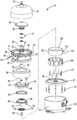
도 2는 도 1의 압축기의 확대 전개도이다.
도 3은 본 발명의 원리에 따른 다른 압축기의 단면도이다.
도 4는 본 발명의 원리에 따른 또 다른 압축기의 단면도이다.
도 5는 본 발명의 원리에 따른 또 다른 압축기의 단면도이다.
도 6은 도 5의 압축기에 대한 다른 단면도이다.
도 7은 본 발명의 원리에 따른 또 다른 압축기의 단면도이다.
도 8은 본 발명의 원리에 따른 또 다른 압축기의 단면도이다.
도 9는 본 발명의 원리에 따른 또 다른 압축기의 단면도이다.
도 10은 도 9의 압축기의 베어링 하우징의 사시도이다.
대응하는 참조 번호들이 여러 도면에 걸쳐 대응하는 부분을 가리킨다.The drawings described herein are merely illustrative of the selected embodiments and are not intended to be all possible implementations and are not intended to limit the scope of the invention.
1 is a cross-sectional view of a compressor in accordance with the principles of the present invention.
2 is an enlarged exploded view of the compressor of FIG.
3 is a cross-sectional view of another compressor in accordance with the principles of the present invention.
4 is a cross-sectional view of another compressor in accordance with the principles of the present invention.
5 is a cross-sectional view of another compressor in accordance with the principles of the present invention.
6 is another cross-sectional view of the compressor of FIG. 5.
7 is a cross-sectional view of another compressor in accordance with the principles of the present invention.
8 is a cross-sectional view of another compressor according to the principles of the present invention.
9 is a cross-sectional view of another compressor in accordance with the principles of the present invention.
10 is a perspective view of a bearing housing of the compressor of FIG. 9.
Corresponding reference numerals indicate corresponding parts throughout the several views.
실시 예들이 첨부된 도면을 참조하여 더 상세히 설명될 것이다.Embodiments will be described in more detail with reference to the accompanying drawings.
실시 예들은 본 발명 개시가 완전해 지고 당 분야에 통상적 지식을 가진 자에게 그 범위를 전체적으로 전달하도록 제공된다. 특정한 세부 수치 정보는 본 발명 개시의 실시 예들의 완전한 이해를 제공하기 위해 특정한 부품, 장치 및 방법의 예들로 주어진다. 당 분야에 통상적 지식을 가진 자는 특정한 세부 정보가 채택될 필요가 없고, 실시 예들이 다수의 서로 다른 형태로 실시될 수 있고 이는 본 발명 개시의 범위를 한정하는 것으로 해석될 수도 없음을 분명히 알 것이다. 어떤 실시 예들에서, 주지의 공정, 주지의 장치 구조 및 주지의 기술은 상세하게 설명되지 않는다.The embodiments are provided so that this disclosure will be thorough, and will fully convey the scope to those skilled in the art. Specific numerical details are given as examples of specific components, devices, and methods to provide a thorough understanding of embodiments of the present disclosure. Those skilled in the art will clearly appreciate that no specific details need to be adopted, and that the embodiments may be embodied in many different forms, which may not be construed as limiting the scope of the present disclosure. In some embodiments, well-known processes, well-known device structures, and well-known techniques are not described in detail.
본 출원 명세서에 사용된 용어는 특정한 실시 예를 설명하기 위한 목적으로 사용될 뿐이며 한정적인 의도가 없다. 본 출원 명세서에 사용된 바와 같이, 단수 형태는 문맥상 명확하게 달리 지칭하지 않는 한 복수 형태도 마찬가지로 포함하는 것으로 의도될 수 있다. 용어, "포함하다", "포함하는", "구비하는" 및 "가지는"은 포괄의 의미로서, 언급된 특징, 정수, 단계, 동작, 요소 그리고/또는 부품이 있다는 것을 나타내나, 하나 이상의 다른 특징, 정수, 단계, 동작, 요소, 부품 그리고/또는 이들의 그룹이 존재하거나 추가되는 경우를 배제하지 않는다. 본 출원 명세서에 설명된 단계, 공정, 및 동작은 실행 순서가 구체적으로 식별되지 않는 한 논의되거나 도시된 특정한 순서로 반드시 실행할 필요가 있는 것으로 해석되지 않는다. 또한, 부가적이거나 대안적인 단계가 채택될 수 있음도 명확하다.The terminology used herein is for the purpose of describing particular embodiments only and is not intended to be limiting. As used herein, the singular forms "a", "an" and "the" are intended to include the plural forms as well, unless the context clearly indicates otherwise. The terms "comprises", "comprising", "comprising" and "having" are intended to be inclusive and mean that there are mentioned features, integers, steps, actions, elements and / or parts, but one or more other It does not exclude the case where features, integers, steps, actions, elements, parts and / or groups thereof are present or added. The steps, processes, and operations described in this application specification are not to be construed as necessarily required to be executed in the specific order discussed or illustrated unless the order of execution is specifically identified. It is also clear that additional or alternative steps may be employed.
하나의 요소 또는 층이 다른 요소 또는 층 "위에", "체결된", "연결된" 또는 "결합된" 것으로 지칭된 경우, 이는 다른 요소 또는 층에 직접적으로 위에 있거나, 체결되거나, 연결되거나 결합된 것일 수 있거나 중간 요소 또는 층이 존재할 수 있다. 반면, 하나의 요소가 다른 요소 또는 층의 "직접적으로 위에", "직접적으로 체결된", "직접적으로 연결된" 또는 " 직접적으로 결합된" 것으로 지칭된 경우, 중간 요소 또는 층이 없을 수 있다. 요소들 간의 관계를 설명하기 위해 사용된 다른 단어들은 유사한 방식으로 해석되어야 한다(예들 들어, "사이에" vs. "직접적으로 사이에", "인접하여" vs. "직접적으로 인접하여" 등). 본 출원 명세서에 사용된 바와 같이 용어 "그리고/또는"은 관련하여 열거된 항목들 중 하나 이상의 임의 조합 및 모든 조합을 포함한다.When one element or layer is referred to as "on", "fastened", "connected" or "coupled" to another element or layer, it is directly on, fastened, connected or coupled to another element or layer. May be present or intermediate elements or layers may be present. On the other hand, where one element is referred to as "directly on", "directly fastened", "directly connected" or "directly coupled" of another element or layer, there may be no intermediate element or layer. Other words used to describe relationships between elements should be interpreted in a similar manner (eg, "between" vs. "directly between", "adjacent" vs. "directly adjacent", etc.). . As used herein, the term "and / or" includes any and all combinations of one or more of the items listed in connection therewith.
본 출원 명세서에서, 제1, 제2, 제3 등의 용어는 다양한 요소, 부품, 영역, 층 그리고/또는 섹션을 설명하기 위해 사용될 수 있으나, 이러한 요소, 부품, 영역, 층 그리고/또는 섹션은 이러한 용어에 의해 한정되지 않아야 한다. 이러한 용어는 하나의 요소, 부품, 영역, 층 또는 섹션을 다른 요소, 부품, 영역, 층 또는 섹션으로부터 구별하기 위한 용도로만 사용될 수 있다. "제1", "제2" 및 다른 수치 용어와 같은 용어는 문맥으로 명백하게 지시되지 않는 한 서열 또는 순서를 암시하지 않는다. 그러므로 이하에 논의되는 제1 요소, 제1 부품, 제1 영역, 제1층 또는 제1 섹션은 실시 예들의 교시를 벗어나지 않고 제2 요소, 제2 부품, 제2 영역, 제2 층 또는 제2 섹션을 지칭할 수 있다.In the present specification, the terms first, second, third, etc. may be used to describe various elements, parts, regions, layers and / or sections, but such elements, parts, regions, layers and / or sections It should not be limited by these terms. This term may only be used to distinguish one element, part, region, layer or section from another element, part, region, layer or section. Terms such as "first", "second", and other numerical terms do not imply a sequence or order unless explicitly indicated in the context. Therefore, the first element, first component, first region, first layer or first section discussed below is intended to be a second element, second component, second region, second layer or second without departing from the teachings of the embodiments. May refer to a section.
"내부", "외부", "아래쪽", "아래에", "하부", "위에", "상부" 등과 같은 공간 관련 용어는 하나의 요소 또는 특징이 도면에 도시된 다른 요소(들) 또는 특징(들)에 대하여 갖는 관계를 용이하게 설명하기 위해 본 출원 명세서에 사용될 수 있다. 공간 관련 용어는 도면에 표시된 방향에 더하여, 사용 또는 동작 시 장치의 다른 방향을 포함하는 것으로 의도될 수 있다. 예를 들어, 도면에서 장치가 뒤집어 져 있는 경우, 다른 요소 또는 특징의 "아래에" 또는 "아래쪽에"로 설명된 요소는 다른 요소 또는 특징의 "위"로 된다. 그러므로 "아래에"라는 예시적 용어는 아래와 위, 양 방향을 모두 포함할 수 있다. 장치는 다른 방식으로 배치될 수 있고(90도 회전 또는 다른 방향으로), 본 출원 명세서에 사용된 공간 관련 설명도 그에 따라 해석될 수 있다.Spatial related terms such as "inner", "outer", "bottom", "below", "bottom", "above", "top", and the like, may refer to one element or other element (s) whose features are shown in the figures or It may be used in the present application specification to easily describe the relationship it has for the feature (s). Space related terms may be intended to include other directions of the device in use or operation, in addition to the directions indicated in the figures. For example, when the device is turned upside down in the figures, an element described as "below" or "below" of another element or feature is "above" the other element or feature. Thus, the example term "below" may include both below and above, both directions. The apparatus may be arranged in other ways (rotated 90 degrees or in other directions), and the spatial descriptions used herein may also be interpreted accordingly.
도 1 및 도 2를 참조하면, 압축기(10)가 제공되며 이 압축기(compressor)(10)는 쉘 어셈블리(shell assembly)(12), 제1 베어링 하우징(first bearing housing)(14), 제2 베어링 하우징(second bearing housing)(16), 압축 메커니즘(compression mechanism)(18) 그리고 모터 어셈블리(motor assembly)(20)를 포함할 수 있다. 쉘 어셈블리(12)는 제1 쉘 바디(first shell body)(22)와 제2 쉘 바디(second shell body)(24)를 포함할 수 있다. 제1 및 제2 쉘 바디(22), (24)는 서로 부착되고 제1 베어링 하우징(14)에 부착될 수 있다. 제1 쉘 바디(22)와 제1 베어링 하우징(14)은 서로 협력하여 흡입 챔버(suction chamber)(26)를 정의하며 이 흡입 챔버(26) 내에 제2 베어링 하우징(16), 압축 메커니즘(18) 그리고 모터 어셈블리(20)가 배치될 수 있다. 흡입 주입구 피팅(suction inlet fitting)(28)(도 2)이 제1 쉘 바디(22)에 체결(engage)될 수 있고 흡입 챔버(26)와 유체 연통(fluid communication)할 수 있다. 흡입-압력 작동 유체(즉, 낮은-압력 작동 유체)가 흡입 유입구 피팅(28)을 통해 흡입 챔버(26)로 들어갈 수 있고, 압축을 위해 압축 메커니즘(18) 안으로 이끌릴 수 있다. 압축기(10)는 저압-측 압축기(low-side compressor)일 수 있다(즉, 모터 어셈블리(20)와, 압축 메커니즘(18)의 적어도 주요 부분이 흡입 챔버(26)에 배치된다).Referring to FIGS. 1 and 2, a
제2 쉘 바디(24)와 제1 베어링 하우징(14)은 서로 협력하여 배출 챔버(discharge chamber)(30)를 정의할 수 있다. 제1 베어링 하우징(14)은, 배출 챔버(30)를 흡입 챔버(26)로부터 분리하도록, 제1 쉘 바디(22)와 제2 쉘 바디(24)에 밀봉 체결된다. 배출 유출구 피팅(discharge outlet fitting)(32)이 제2 쉘 바디(24)에 체결될 수 있고, 배출 챔버(30)와 유체 연통할 수 있다. 배출-압력 작동 유체(즉, 흡입 압력보다 높은 압력의 작동 유체)가 압축 메커니즘(18)으로부터 배출 챔버(30)로 들어갈 수 있고 배출 유출구 피팅(32)을 통해 압축기(10)에서 배출된다. 몇몇 구성들에서, 배출 밸브(34)가 배출 유출구 피팅(32) 내에 배치될 수 있다. 배출 밸브(34)는, 배출 유출구 피팅(32)을 통해서 유체가 배출 챔버(30)에서 배출되는 것은 허용하고 배출 유출구 피팅(32)을 통해서 유체가 배출 챔버(30)로 유입되는 것은 방지하는, 체크 밸브(check valve)일 수 있다.The
몇몇 구성들에서, 고압-측 윤활제 섬프(high-side lubricant sump)(36)가 배출 챔버(30)에 배치될 수 있다. 즉, 제2 쉘 바디(24)와 제1 베어링 하우징(14)은 서로 협력하여 윤활제 섬프(36)를 정의할 수 있다. 배출-압력 작동 유체와 윤활제의 혼합물이 압축 메커니즘(18)으로부터 제1 베어링 하우징(14)에 장착된 배출 파이프(38)를 통해 배출될 수 있다. 배출 파이프(38)는 배출-압력 작동 유체와 윤활제의 혼합물을, 배출-압력 작동 유체로부터 윤활제를 분리하는 윤활제 분리기(lubricant separator)(40)로 인도할 수 있다. 분리된 윤활제는 윤활제 분리기(40)에서 낙하하여 윤활제 섬프(36) 내로 모일 수 있고 분리된 배출-압력 작동 유체는 배출 유출구 피팅(32)으로 이동할 수 있다.In some configurations, a high-
제1 베어링 하우징(14)은 전반적으로 원통형인 환상 벽(annular wall)(42)과, 환상 벽(42)의 축방향 단부에 배치된 반경방향 신장 플랜지부(radially extending flange portion)(44)를 포함할 수 있다. 환상 벽(42)은 하나 이상의 개구(opening) 또는 구멍(aperture)(46)(도 2)을 포함하며 이 구멍을 통해 흡입 챔버(26)의 흡입-압력 작동 유체가 압축 메커니즘(18)으로 흐를 수 있다. 플랜지부(44)는 제1 및 제2 쉘 바디(22), (24)에 용접(또는 다른 방식으로 고정 체결)된 외부 림(outer rim)(48)을 포함할 수 있다. 플랜지부(44)는 제1 베어링(52)을 수용하는 중앙 허브(central hub)(50)를 포함할 수 있다. 배출 파이프(38)는 중앙 허브(50)에 장착될 수 있다. 중앙 허브(50)는 배출 통로(54)를 정의할 수 있는데, 이 배출 통로(54)를 통해 배출-압력 작동 유체가 압축 메커니즘(18)으로부터 배출 파이프(38)로 흐른다.The
제1 베어링 하우징(14)은 환상 벽(42)과 플랜지부(44)를 통과해 신장하며 윤활제 섬프(36)와 유체 연통하는 축방향 신장 윤활제 통로(axially extending lubricant passage)(56)를 포함할 수 있다. 플랜지부(44)는 또한 축방향 신장 윤활제 통로(56)와 유체 연통하는 제1 반경방향 신장 윤활제 통로(first radially extending lubricant passage)(58)와 제1 베어링(52)을 통과해 신장하는 구멍(aperture)(60)을 포함할 수 있다. 밸브 어셈블리(62)가 플랜지부(44)에 장착될 수 있고 윤활제가 윤활제 섬프(36)로부터 축방향 신장 윤활제 통로(56)로 흐르는 것을 선택적으로 허용 및 차단할 수 있다. 윤활제는 축방향 신장 윤활제 통로(56)로부터 제1 반경방향 신장 윤활제 통로(58)와 구멍(60)으로 흐를 수 있다. 밸브 어셈블리(62)는, 윤활제가 윤활제 섬프(36)로부터 축방향 신장 윤활제 통로(56)로 흐르는 것을 허용 및 차단하도록 하는, 밸브 하우징(65) 내에서 개방 위치 및 폐쇄 위치 사이에서 이동할 수 있는 밸브 부재(예를 들어 볼(ball))(64)를 포함할 수 있다. 배출 챔버(30)의 작동 유체 및 윤활제의 압력이 밸브 부재(64)를 개방 위치로 되게 할 수 있다. 스프링(66)이 밸브 부재(64)를 폐쇄 위치로 바이어스 할 수 있다.The
제2 베어링 하우징(16)은 제2 베어링(69)을 수용하는 중앙 허브(central hub)(68)를 구비하는 전반적으로 원판 형상 부재일 수 있다. 제2 베어링 하우징(16)은 예를 들어 다수의 패스너(fastener)(70)를 통해 제1 베어링 하우징(14)의 환상 벽(42)의 축방향 단부(axial end)에 고정 부착될 수 있다. 제2 베어링 하우징(16)은 제1 베어링 하우징(14)의 축방향 신장 윤활제 통로(56)와 유체 연통하는 제2 반경방향 신장 윤활제 통로(72)와 제2 베어링(69)을 통과해 신장하는 구멍(74)을 포함할 수 있다. 윤활제는 축방향 신장 윤활제 통로(56)로부터 제2 반경방향 신장 윤활제 통로(72)와 구멍(74)으로 흐를 수 있다.The
압축 메커니즘(18)은 제1 압축 부재와 제2 압축 부재를 포함할 수 있고, 제1 압축 부재와 제2 압축 부재는 함께 그 사이에 유체 포켓들(fluid pockets)(즉 압축 포켓들)을 정의한다. 예를 들어, 압축 메커니즘(18)은, 제1 압축 부재가 제1 스크롤 부재(즉 종동 스크롤 부재(driven scroll member))(76)이고 제2 압축 부재가 제2 스크롤 부재(즉 아이들러 스트롤 부재(idler scroll member))(78)인, 동방향 회전(co-rotating) 스크롤 압축 메커니즘일 수 있다. 다른 구성들에서, 압축 메커니즘(18)은, 선회압축 메커니즘(orbiting scroll compression mechanism), 회전 압축 메커니즘(rotary compression mechanism), 나사 압축 메커니즘(screw compression mechanism), 방켈 압축 메커니즘(Wankel compression mechanism)과 같은 또는 예를 들어 왕복 압축 메커니즘(reciprocating compression mechanism) 같은 압축 메커니즘일 수 있다.The
제1 스크롤 부재(76)는 제1 단부 플레이트(first end plate)(80), 제1 나선형 랩(first spiral wrap)(82) 및 제1 허브(84)를 포함할 수 있고, 제1 나선형 랩(82)은 제1 단부 플레이트(80)의 일측으로부터 신장하고, 제1 허브(84)는 제1 단부 플레이트(80)의 타측으로부터 신장한다. 제2 스크롤 부재(78)는 제2 단부 플레이트(86), 제2 나선형 랩(88) 및 제2 허브(90)를 포함할 수 있고, 제2 나선형 랩(88)은 제2 단부 플레이트(86)의 일측으로부터 신장하고, 제2 허브(90)는 제2 단부 플레이트(86)의 타측으로부터 신장한다. 제1 스크롤 부재(76)의 제1 허브(84)는 제1 베어링 하우징(14)의 중앙 허브(50) 내에 수용되고, 제1 베어링 하우징(14) 및 제2 베어링 하우징(16)에 대해 상대적으로 제1 회전 축(A1) 주위의 회전이 가능하도록 제1 베어링 하우징(14) 및 제1 베어링(52)에 의해 지지된다. 밀봉 부재(seal)(85)가 중앙 허브(50) 내에 배치되고 중앙 허브(50)와 제1 허브(84)에 밀봉 체결된다. 제2 스크롤 부재(78)의 제2 허브(90)는 제2 베어링 하우징(16)의 중앙 허브(68) 내에 수용되고, 제1 베어링 하우징(14) 및 제2 베어링 하우징(16)에 대해 상대적으로 제2 회전 축(A2) 주위의 회전이 가능하도록 제2 베어링 하우징(16) 및 제2 베어링(69)에 의해 지지된다.The
제2 회전 축(A2)은 제1 회전 축(A1)과 평행하며, 제1 회전 축(A1)으로부터 벗어나(offset) 있다. 스러스트 베어링(thrust bearing)(91)이 제2 베어링 하우징(16)의 중앙 허브(68) 내에 배치될 수 있고, 제2 스크롤 부재(78)의 제2 허브(90)의 축방향 단부를 지지할 수 있다.The second axis of rotation A2 is parallel to the first axis of rotation A1 and is offset from the first axis of rotation A1. A
올드햄 커플링(Oldham coupling)(92)이 제1 단부 플레이트(80) 및 제2 단부 플레이트(86)에 삽입연결될(keyed) 수 있다. 몇몇 구성들에서, 올드햄 커플링(92)은 제2 단부 플레이트(86)와 모터 어셈블리(20)의 회전자(100)에 삽입연결될 수 있다. 제1 나선형 랩(82)과 제2 나선형 랩(88)은 서로 맞물려 연결되어(intermesh) 다수의 유체 포켓(압축 포켓)을 형성한다. 제1 회전 축(A1) 둘레의 제1 스크롤 부재(76)의 회전 및 제2 회전 축(A2) 둘레의 제2 스크롤 부재(78)의 회전은, 반경방향 외측 위치(radially outer position)로부터 반경방향 내측 위치로 이동함에 따라 유체 포켓들의 크기를 감소시키고, 이에 따라 작동 유체를 흡입 압력에서 배출 압력으로 압축하게 된다.
제1 단부 플레이트(80)는, 흡입 챔버(26)와 유체 포켓들 중 반경방향 최외측 포켓 사이의 유체 연통을 제공하는 흡입 유입구 개구(suction inlet opening)(94), (도 2)를 포함할 수 있다. 제1 스크롤 부재(76)는 또한 제1 단부 플레이트(80)와 제1 허브(84)를 통과해 신장하고, 유체 포켓들 중 반경방향 최내측 포켓과 배출 챔버(30) 사이에 유체 연통을 제공하는 (예를 들어 배출 통로(54)와 배출 파이프(38)를 경유해서) 배출 통로(96)를 포함할 수 있다. 배출 밸브 어셈블리(97)가 배출 통로(54) 내에 배치될 수 있다. 배출 밸브 어셈블리(97)는 작동 유체가 압축 메커니즘(18)으로부터 배출 통로(96)를 통과해서 배출 챔버(30) 안으로 배출되도록 하고, 작동 유체가 배출 챔버(30)로부터 배출 통로(96)로 거꾸로 흐르는 것을 방지한다.The
제2 스크롤 부재(78)의 제2 허브(90)는 배유관(scavenging tube)(99)을 수용할 수 있으며 이 배유관(99)은 압축기(10) 작동 중에 제1 쉘 바디(22)의 바닥으로부터 오일을 배출할 수 있다. 즉, 제1 쉘 바디(22) 바닥의 오일이 배유관(99)을 통해서 위쪽으로 끌어올려 질 수 있고, 하나 이상의 윤활제 통로를 경유하여 압축기(10)의 하나 이상의 가동부(moving part)로 안내될 수 있다. 몇몇 구성들에서, 제2 스크롤 부재(78)는 하나 이상의 오일 주입 통로(미도시)를 포함할 수 있고, 배유관(99)으로부터 이 오일 주입 통로를 통과해서 오일이 압축 포켓들 중 하나로 주입될 수 있다.The
모터 어셈블리(20)는 링-모터(ring-motor)일 수 있고, 복합 고정자(composite stator)(98)와 회전자(rotator)(100)를 포함할 수 있다. 고정자(98)는 제1 베어링 하우징(14)의 환상 벽(42)의 내경면(inner diametrical surface)(101)에 고정될 수 있다. 고정자(98)는 제1 단부 플레이트(80) 및 제2 단부 플레이트(86)와 제1 나선형 랩(82) 및 제2 나선형 랩(88)을 둘러쌀 수 있다.The
회전자(100)는 고정자(98)의 반경방향 내측에 배치될 수 있고, 고정자(98)에 대해서 상대적으로 회전한다. 회전자(100)는 제1 회전 축(A1)에 평행하게 신장하는 환상 축방향 신장부(102)와, 축방향 신장부(102)의 축방향 단부로부터 반경방향 내측으로(즉 제1 회전 축(A1)에 대해서 수직 방향) 신장하는 반경방향 신장부(104)를 포함할 수 있다. 축방향 신장부(102)는 제1 단부 플레이트(80) 및 제2 단부 플레이트(86)와 제1 나선형 랩(82) 및 제2 나선형 랩(88)을 둘러쌀 수 있다. 축방향 신장부(102)의 내경면(106)은 제1 단부 플레이트(80)의 외주(outer periphery)에 체결될 수 있다. 자석(108)들이 축방향 신장부(102)의 외경면(outer diametrical surface)(110)에 고정될 수 있다. 패스너(102)들이, 회전자(100)를 제1 스크롤 부재(76)에 회전가능하게 그리고 축방향으로 고정하도록, 반경방향 신장부(104) 및 제1 단부 플레이트(80)에 체결될 수 있다. 따라서, 전류가 고정자(98)에 제공될 때, 회전자(100)와 제1 스크롤 부재(76)는 제1 회전 축(A1) 둘레를 회전한다. 이 같은 제1 스크롤 부재(76)의 회전은, 제1 스크롤 부재(76) 및 제2 스크롤 부재(78)와 올드햄 커플링(92)의 체결로 인해, 제2 회전 축(A2) 둘레의 제2 스크롤 부재(78)의 회전을 야기한다.The
회전자(100)의 반경방향 신장부(104)는 중앙 구멍(114)을 포함할 수 있으며 이 구멍(114)을 통해서 제2 스크롤 부재(78)의 제2 허브(90)가 신장한다. 반경방향 신장부(104)는 또한 환상 오목부(annular recess)(116)를 포함할 수 있으며 이 환상 오목부(116)는 중앙 구멍(114)과 제1 및 제2 회전 축(A2), (A2)을 둘러싼다. 제1 환상 밀봉 부재(118) 및 제2 환상 밀봉 부재(119)가 오목부(116) 내에 적어도 부분적으로 수용될 수 있고 반경방향 신장부(104)와 제2 단부 플레이트(86)에 밀봉 체결된다. 제2 환상 밀봉 부재(119)는 제1 환상 밀봉 부재(118)를 둘러쌀 수 있다. 이로 인해, 제1 및 제2 환상 밀봉 부재(118), (119), 제2 단부 플레이트(86) 및 반경방향 신장부(104)는 협력하여 환상 챔버(120)를 정의한다. 환상 챔버(120)는 (흡입 압력보다 크고 배출 압력보다 낮은 압력의) 중간-압력 작동 유체를 제2 단부 플레이트(86)의 통로(124)를 경유하여 중간 유체 포켓(122)로부터 받을 수 있다. 환상 챔버(120)의 중간-압력 작동 유체는 축 방향(즉, 회전 축(A1), (A2)에 평행한 방향)에서 제2 단부 플레이트(86)를 제1 단부 플레이트(80)를 향해 바이어스 하여 제1 나선형 랩(82)의 선단(tip)과 제2 단부 플레이트(86)의 선단 사이의 밀봉과, 제2 나선형 랩(88)의 선단과 제1 단부 플레이트(80)의 선단 사이의 밀봉을 향상시킨다.The
도 3을 참조하면, 또 다른 압축기(200)가 제공되며, 이 압축기(200)는 쉘 어셈블리(212), 제1 베어링 하우징(214), 제2 베어링 하우징(216), 압축 메커니즘(218), 및 모터 어셈블리(220)를 포함할 수 있다. 쉘 어셈블리(212)는 제1 쉘 바디(222)와 제2 쉘 바디(224)를 포함할 수 있으며 제2 쉘 바디(224)는 제1 쉘 바디(222)에 (예를 들어 용접, 압력 끼워맞춤(press fit) 등을 통해) 부착된다. 제1 및 제2 쉘 바디(222), (224)는 협력하여 배출 챔버(230)를 정의할 수 있으며 이 배출 챔버(230) 내에 제1 및 제2 베어링 하우징(214), (216), 압축 메커니즘(218) 및 모터 어셈블리(220)가 배치될 수 있다. 따라서, 압축기(200)는 고압-측 압축기이다(즉, 모터 어셈블리(220)와, 압축 메커니즘(218)의 적어도 주요 부분이 배출 챔버(230) 내에 배치된다). 제1 쉘 바디(222)의 바닥은 윤활제 섬프(236)를 정의할 수 있으며 이 윤활제 섬프(236)는 다량의 윤활제를 저장할 수 있다.Referring to FIG. 3, another compressor 200 is provided, which includes a
배출 유출구 피팅(232)은 제2 쉘 바디(224)와 체결될 수 있고 배출 챔버(230)와 유체 연통할 수 있다. 배출-압력 작동 유체(즉, 흡입 압력보다 높은 압력의 작동 유체)는 압축 메커니즘(218)으로부터 배출 챔버(230)로 들어가고 배출 유출구 피팅(232)을 통과해 압축기를 빠져나갈 수 있다. 어떤 구성들에서, 배출 밸브(234)가 배출 유출구 피팅(232) 내에 배치될 수 있다. 배출 밸브(234)는 유체가 배출 유출구 피팅(232)을 통과해서 나가는 것은 허용하지만, 배출 유출구 피팅(232)를 통과해서 배출 챔버(230)로 들어가는 것은 방지하는, 체크 밸브일 수 있다.The outlet outlet fitting 232 may be engaged with the
제1 베어링 하우징(214)은 전반적으로 원통형인 환상 벽(242)과, 이 환상 벽(242)의 축 방향 단부에 배치된 반경방향 플랜지부(244)를 포함할 수 있다. 환상 벽(242)은, 제1 쉘 바디(222) 안으로 압입될 수 있는 외부 림을 포함할 수 있다. 플랜지부(244)는 중앙 허브(250)를 포함할 수 있으며 이 중앙 허브(250)는 제1 베어링 하우징(252)을 수용한다. 중앙 허브(250)는 흡입 통로(254)를 정의할 수 있는데, 이 흡입 통로(254)를 통해서 흡입-압력 작동 유체가 압축 메커니즘(218) 안으로 빨려들어갈 수 있다. 중앙 허브(250)는 제2 쉘 바디(224)의 개구(opening)를 통과해 신장할 수 있고, 흡입 유입구 피팅(228)과 체결될 수 있다. 흡입 밸브 어셈블리(229), (예를 들어 체크 밸브)가 흡입 통로(254) 내에 배치될 수 있다. 흡입 밸브 어셈블리(229)는 흡입-압력 작동 유체가 흡입 통로(254)를 통과해서 압축기(218)로 흐르는 것은 허용하지만, 그 반대 방향으로의 작동 유체의 흐름은 차단할 수 있다.The
제1 베어링 하우징(214)은, 환상 벽(242)을 통과해 신장하고 윤활제 섬프(236)와 연통하는 축 방향 신장 윤활제 통로(256)와, 제1 플랜지부(244)에 형성된 제1 반경방향 신장 윤활제 통로(258)를 포함할 수 있다. 중앙 허브(250)는, 제1 반경방향 신장 윤활제 통로(258)와 유체 연통하는 제2 윤활제 통로(259)와 제1 베어링(252)을 통과해 신장하는 구멍(260)을 포함할 수 있다. 제1 베어링 하우징(214)은 또한 배출 통로(255)를 포함할 수 있으며 압축 메커니즘(218)으로부터 이 배출 통로(255)를 통과해서 작동 유체가 배출될 수 있다.The
제2 베어링 하우징(216)은 제2 베어링(269)을 수용하는 중앙 허브(268)를 구비하는 전반적으로 원판-형상의 부재이다. 제2 베어링 하우징(216)은 예를 들어 다수의 패스너(270)를 사용하여 제1 베어링 하우징(214)의 환상 벽(242)의 축방향 단부에 고정 부착될 수 있다. 윤활제 도관(lubricant conduit)(272)이 제2 베어링 하우징(216)의 개구를 통과해 신장할 수 있고, 윤활제 섬프(236)와 제1 베어링 하우징(214)의 축방향 신장 윤활제 통로(256) 사이의 유체 연통을 제공할 수 있다. 압축기(210)의 작동 중에, 흡입 통로(254)의 낮은-압력 가스와 배출 챔버(230)의 높은 압력 가스 간의 압력차는 윤활제가 윤활제 섬프(236)로부터 윤활제 도관(272)을 통과하고, 축방향 신장 윤활제 통로(256)를 통과하고, 제1 반경방향 신장 윤활제 통로(258)를 통과하고, 제2 윤활제 통로(259)를 통과하고 그리고 제1 베어링 하우징(252)의 구멍(260)을 통과해서 흐르도록 한다. 제1 베어링(252)으로부터, 윤활제는 압축 메커니즘(218) 안으로 흘러들어간다. 제2 베어링 하우징(216)은 배액 통로(drain passage)(271)를 포함할 수 있으며, 윤활제는 이 배액 통로(271)를 통과하여 압축 메커니즘(218)과 모터 어셈블리(220)로부터 배출되어 윤활제 섬프(236)로 흐른다.The
압축 메커니즘(218)은 제1 스크롤 부재(즉 종동 스크롤 부재(driven scroll member))(276)와 제2 스크롤 부재(즉 아이들러 스트롤 부재(idler scroll member))(278)를 포함하는 동방향 회전(co-rotating) 스크롤 압축 메커니즘일 수 있다. 제1 스크롤 부재(276)는 제1 단부 플레이트(280), 상기 제1 단부 플레이트(280)의 일측에서 신장하는 제1 나선형 랩(282) 및 상기 제1 단부 플레이트(280)의 타측에서 신장하는 제1 허브(284)를 포함할 수 있다. 제2 스크롤 부재(278)는 제2 단부 플레이트(286), 상기 제2 단부 플레이트(286)의 일측에서 신장하는 제2 나선형 랩(288) 및 상기 제2 단부 플레이트(286)의 타측에서 신장하는 제2 허브(290)를 포함할 수 있다. 제1 스크롤 부재(276)의 제1 허브(284)는 제1 베어링 하우징(214)의 중앙 허브(250) 내에 수용되고, 제1 및 제2 베어링 하우징(214), (216)에 대해서 상대적으로 제1 회전 축(A1) 둘레의 회전을 위해 제1 베어링 하우징(214) 및 제1 베어링(252)에 의해 지지가 된다. 밀봉 부재(285)는 중앙 허브(250) 내에 배치되고 중앙 허브(250)와 밀봉 체결된다. 제2 스크롤 부재(278)의 제2 허브(290)는 제2 베어링 하우징(216)의 중앙 허브(268) 내에 배치되고, 제1 및 제2 베어링 하우징(214), (216)에 대해서 상대적으로 제2 회전 축(A2) 둘레의 회전을 위해 제2 베어링 하우징(216) 및 제2 베어링(269)에 의해 지지가 된다. 제2 회전 축(A2)은 제1 회전 축(A1)과 평행하며, 제1 회전 축(A1)에서 벗어나 있다. 스러스트 베어링(291)은 제2 베어링 하우징(216)의 중앙 허브(268) 내에 배치될 수 있고 제2 스크롤 부재(278)의 제2 허브(290)의 축방향 단부를 지지할 수 있다.
올드햄 커플링(미도시)이 제1 및 제2 단부 플레이트(280), (286)에 삽입연결될 수 있다. 제1 및 제2 나선형 랩(282), (288)은 서로 맞물리어 그 사이에 다수의 유체 포켓(즉 압축 포켓)을 형성한다. 제1 회전 축(A1) 둘레의 제1 스크롤 부재(276)의 회전 및 제2 회전 축(A2) 둘레의 제2 스크롤 부재(278)의 회전은, 반경방향 외측 위치로부터 반경방향 내측 위치로 이동함에 따라 유체 포켓들의 크기를 감소시키고, 이에 따라 작동 유체를 흡입 압력에서 배출 압력으로 압축하게 된다.Oldham couplings (not shown) may be inserted into the first and
제1 스크롤 부재(276)는 제1 허브(284)를 통과하여 제1 단부 플레이트(280) 안으로 신장하는 축방향 신장 흡입 통로(296)를 포함할 수 있다. 축방향 신장 흡입 통로(296)는 제1 회전 축(A1)을 따라 축방향으로 신장할 수 있다(즉 축방향 신장 흡입 통로(296)는 제1 회전 축(A1) 중심에 위치할 수 있다. 제1 단부 플레이트(280)에 형성된 반경방향 신장 흡입 통로(297)는 축방향 신장 흡입 통로(296)로부터 반경방향 외측으로 신장하며, 축방향 신장 흡입 통로(296)와 반경방향 최외측 유체 포켓 사이의 유체 연통을 제공한다. 따라서, 압축기(210)의 작동 중에, 흡입-압력 작동 유체는 흡입 유입구 피팅(228) 안으로 빨려들어가고, 제1 베어링 하우징(214)의 흡입 통로(254)를 통과하고, 축방향 신장 흡입 통로(296)를 통과하고 이어 반경방향 신장 흡입 통로(297)를 통과하여 나선형 랩(282), (288)에 의해 정의된 반경방향으로 최외측 유체 포켓으로 들어간다.The
도 3에 도시되고 위에서 서술한 반경방향 신장 흡입 통로(297) 및 축방향 신장 흡입 통로(296)의 구성은 작동 유체가 반경방향에서 최외측 유체 포켓 안으로 유입되는 것을 돕는다. 즉, 제1 스크롤 부재(276)의 회전에 따른 원심력이 작동 유체를 축방향 신장 흡입 통로(296)로부터 반경방향 외측으로 반경방향 신장 흡입 통로(297)를 통과하도록 한다. 환언하면, 작동 유체를 반경방향 신장 흡입 통로(297)를 통과해서 반경반향에서 최외측 포켓으로 끌어들이는 압력의 차이뿐만 아니라, 제1 스크롤 부재(276)의 회전에 따른 원심력도 작동 유체를 반경방향 신장 흡입 통로(297)를 통과해서 반경반향에서 최외측 포켓으로 흐르도록 한다. 더욱이, 축방향 신장 흡입 통로(296)와 반경방향 신장 흡입 통로(297)는 또한 스크롤 부재(276), (278)의 회전에 따른 원심성 풍손(centrifugal windage loss)으로부터 작동 유체를 보호한다. 더욱이, 원심성 바람(centrifugal windage)으로부터 작동 유체의 보호는 점성 전단(sheath) 및 공기역학 효과에 의해 발생하는 열에 의해 작동 유체가 데워지는 것을 방지 혹은 감소시킨다.The configuration of the radially extending
제2 스크롤 부재(278)는, 제2 단부 플레이트(286)를 통과해 신장하고 반경방향 최내측 유체 포켓과 배출 챔버(230) 사이에 유체 연통을 제공하는 하나 이상의 배출 통로(294)를 포함한다. 제2 스크롤 부재(278)의 제2 허브(290)는, 압축기(210)의 작동 중에 윤활제 섬프(236)로부터 오일을 배출할 수 있는 배유관(299)을 수용할 수 있다. 즉, 제1 쉘 바디(22)의 바닥 상의 오일이 제2 허브(290)의 구멍(298)을 통과해 제2 베어링(269)으로 흐를 수 있다.The
모터 어셈블리(220)의 구조 및 기능은 모터 어셈블리(20)의 구조 및 기능과 비슷하거나 동일하다. 따라서, 비슷한 특징들에 대해서는 다시 상세히 설명하지 않는다. 모터 어셈블리(20)와 마찬가지로, 모터 어셈블리(200)는 복합 고정자(295)와 회전자(300)를 포함하는 링 모터일 수 있다. 고정자(295)는 제1 베어링 하우징(214)의 환상 벽(242)에 고정될 수 있고 제1 및 제2 단부 플레이트(280), (286)와 제1 및 제2 나선형 랩(282), (288)을 둘러쌀 수 있다.The structure and function of the
회전자(300)는 고정자(295)의 반경 방향 내측에 배치될 수 있고 고정자(295)에 대해 회전 가능하다. 회전자(100)와 마찬가지로, 회전자(300)는 환상의 축방향 신장부(302) 및 반경 방향 신장부(304)를 포함할 수 있다. 축방향 신장부(302)는 제1 및 제2 단부 플레이트(280), (286)와 제1 및 제2 나선형 랩(282), (288)을 둘러쌀 수 있다. 축방향 신장부(302)은 제1 단부 플레이트(280)의 외측 연부(outer periphery)와 체결될 수 있다. 전류가 고정자(298)에 제공될 때, 회전자(300) 및 제1 스크롤 부재(276)는 제1 회전축(A1)을 중심으로 회전한다. 제1 스크롤 부재(276)의 이러한 회전은 전술한 바와 같이 제2 스크롤 부재(278)가 제2 회전축(A2)을 중심으로 대응 회전하게 한다.The
반경방향 신장부(304)는 제1 및 제2 회전축(A1), (A2)을 둘러싸는 환상 오목 부(316)를 포함할 수 있다. 환상 밀봉 부재(318)가 환상 오목부(316) 내에 수용될 수 있고, 반경방향 신장부(304)와 제2 단부 플레이트(286)에 밀봉 체결될 수 있다. 환상 밀봉 부재(318), 제1 및 제2 단부 플레이트(280), (286) 그리고 축방향 신장부(304)는 협력하여 환상 챔버(320)를 정의한다. 환상 챔버(320)는 제2 단부 플레이트(286)의 통로(324)를 통해 중간 유체 포켓(322)으로부터 중간-압력 작동 유체(흡입 압력보다 크고 배출 압력보다 작은 압력에서)를 받을 수 있다. 환상 챔버(320) 내의 중간-압력 작동 유체는 제1 단부 플레이트(280)를 향해서 축방향(즉, 회전 축(A1), (A2)에 평행한 방향)으로 제2 단부 플레이트(286)를 바이어스 하여 제1 나선형 랩(282)의 선단 및 제2 단부 플레이트(286)의 선단 간의 밀봉 및 제2 나선형 랩(288)의 선단 및 제1 단부 플레이트(280)의 선단 간의 밀봉을 향상시킨다.The
도 4를 참조하면, 쉘 어셈블리(412), 제1 베어링 하우징(414), 제2 베어링 하우징(416), 압축 메커니즘(418) 및 모터 어셈블리(420)를 포함할 수 있는 다른 압축기(410)가 제공된다. 쉘 어셈블리(412)는 제1 쉘 바디(422) 및 제2 쉘 바디(424)를 포함할 수 있다. 제1 및 제2 쉘 바디(422), (424)는 서로 고정되고 제1 베어링 하우징(414)에 고정될 수 있다. 제2 쉘 바디(424) 및 제1 베어링 하우징(414)은 서로 협력하여 흡입 챔버(426)를 정의할 수 있으며 이 흡입 챔버(426) 내에 제2 베어링 하우징(416), 압축 메커니즘(418) 및 모터 어셈블리(420)가 배치될 수 있다. 흡입 유입구 피팅(428)은 제2 쉘 바디(424)와 체결될 수 있고 흡입 챔버(426)와 유체 연통할 수 있다. 흡입 압력 작동 유체(즉, 낮은 압력 작동 유체)는 흡입 유입구 피팅(428)을 통해 흡입 챔버(426)로 들어갈 수 있고, 거기서 압축을 위해 압축 메커니즘(418) 안으로 흡입될 수 있다. 압축기(410)는 저압측 압축기일 수 있다.4, another
제1 쉘 바디(422)와 제1 베어링 하우징(414)은 서로 협력하여 배출 챔버(430)를 정의할 수 있다. 제1 베어링 하우징(414)은 제1 및 제2 쉘 바디(422), (424)에 밀봉 체결되어 배출 챔버(430)를 흡입 챔버(426)로부터 분리한다. 배출 유출구 피팅(432)은 제1 쉘 바디(422)에 체결될 수 있고 배출 챔버(430)와 유체 연통할 수 있다. 배출-압력 작동 유체(즉, 흡입 압력보다 높은 압력에서의 작동 유체)는 압축 메커니즘(418)으로부터 배출 챔버(430)로 들어갈 수 있고, 배출 유출구 피팅(432)을 통해 압축기(410)에서 배출될 수 있다. 어떤 구성들에서, 배출 밸브(434)는 배출 유출구 피팅(432) 내에 배치될 수 있다. 배출 밸브(434)는 유체가 배출 유출구 피팅(432)를 통해 배출 챔버(430)를 빠져나갈 수 있게 하는 반면 배출 유출구 피팅(432)을 통해 배출 챔버(430)로 유입되는 것을 방지하는, 체크 밸브일 수 있다. 제1 쉘 바디(422)는 배출 챔버(430) 내에 배치된 고압-측 윤활제 섬프(436)를 정의 할 수 있다.The
제1 베어링 하우징(414)은 대체로 원통형인 환상 벽(442) 및 이 환상 벽(442)의 축 방향 단부에 배치된 반경방향 신장 플랜지부(444)를 포함할 수 있다. 환상 벽(442)은 제1 및 제2 쉘 바디(22), (24)에 용접(또는 다른 방식으로 부착 체결)된 외부 림(448)을 포함할 수 있다. 플랜지부(444)는 제1 베어링(452)을 수용하는 중앙 허브(450)를 포함할 수 있다. 오일 분리기(oil separator)(예를 들어, 환상 슈라우드(annular shroud))(438)는 중앙 허브(450)에 장착될 수 있다 중앙 허브(450)는 압축 메커니즘(418)으로부터 오일 분리기(438)로 배출-압력 작동 유체가 흐르는 배출 통로(454)를 정의할 수 있다. 오일 분리기(438)에서 배출 챔버(430)로 배출-압력 작동 유체가 유입된다.The
제1 베어링 하우징(414)은 환상 벽(442) 및 플랜지부(444)를 통해 신장하며, 윤활제 도관(457)을 경유해 윤활제 섬프(436)와 유체 연통하는 축방향 신장 윤활제 통로(456)를 포함할 수 있다. 플랜지부(444)는 또한 축방향 신장 윤활제 통로(456)와 유체 연통하는 제1 반경방향 연장 윤활제 통로(458)와 제1 베어링(452)을 통해 신장되는 구멍(460)을 포함할 수 있다.The
제2 베어링 하우징(416)은 제2 베어링(469)을 수용하는 중앙 허브(468)를 갖는 대체로 원판 형상인 부재일 수 있다. 제2 베어링 하우징(416)은 예를 들어 다수의 패스너(470)를 통해 제1 베어링 하우징(414)의 환상 벽(442)의 축방향 단부에 고정 부착될 수 있다. 제2 베어링 하우징(416)은 제1 베어링 하우징(414) 내의 축 방향 신장 윤활제 통로(456) 및 제2 베어링(469)을 통과해 신장하는 구멍(474)과 유체 연통하는 제2 반경방향 신장 윤활제 통로(472)를 포함할 수 있다. 윤활제는 축방향 신장 윤활제 통로(456)에서 제2 반경방향 신장 윤활제 통로(472)와 구멍(474)로 흐를 수 있다. 제2 베어링 하우징(416)은 흡입 챔버(426) 내의 흡입-압력 작동 유체가 압축 메커니즘(418)으로 흐를 수 있는 하나 이상의 개구 또는 구멍(446)을 포함할 수 있다.The
압축 메커니즘(418)은 제1 스크롤 부재(종동 스크롤 부재) (476) 및 제2 스크롤 부재(아이들러 스크롤 부재) (478)를 포함하는 동방향-회전 스크롤 압축 메커니즘일 수 있다. 제1 스크롤 부재(476)는 제1 단부 플레이트(480), 제1 단부 플레이트(480)의 일측으로부터 신장되는 제1 나선형 랩(482), 및 상기 일 측면의 반대측인 제1 단부 플레이트(480)의 타측으로부터 신장되는 제1 허브(484)를 포함할 수 있다. 제2 스크롤 부재(478)는, 제2 단부 플레이트(486), 상기 제2 단부 플레이트(486)의 일측으로부터 연장되는 제2 나선형 랩(488), 및 상기 제2 단부 플레이트(486)의 타측으로부터 연장되는 제2 허브(490)를 포함한다. 제1 스크롤 부재(476)의 제1 허브(484)는 제2 베어링 하우징(416)의 중앙 허브(468) 내에 수용되고, 제1 및 제2 베어링 하우징(414), (416)에 대해 제1 회전축(A1)을 중심으로 회전하도록 제2 베어링 하우징(416) 및 제2 베어링(469)에 의해 지지가 된다. 스러스트 베어링(485)은 중앙 허브(468) 내에 배치된다.The
제2 스크롤 부재(478)의 제2 허브(490)는 제1 베어링 하우징(414)의 중앙 허브(450) 내에 수용되고, 제1 베어링 하우징(414) 및 제2 베어링 하우징(416)에 대해서 제2 회전축(A2)을 중심으로 한 회전을 위해 제1 베어링 하우징(414) 및 제1 베어링(452)에 의해 지지가 된다. 제2 회전축(A2)은 제1 회전축(A1)과 평행하며 제1 회전축(A1)으로부터 벗어나 있다. 밀봉 부재(491)는 제1 베어링 하우징(414)의 중앙 허브(450) 내에 배치될 수 있고 제2 스크롤 부재(478)의 제2 허브(490) 및 중앙 허브(450)와 밀봉식으로 결합 할 수 있다.The
올드햄 커플링은 제1 및 제2 단부 플레이트(480), (486)에 삽입 체결될 수 있다. 제1 및 제2 나선형 랩(482), (488)은 서로 맞물려 협력하여 그들 사이에 복수의 유체 포켓 (즉, 압축 포켓)을 형성할 수 있다. 제1 스크롤 부재(476)가 제1 회전축(A1)을 중심으로 회전하고 제2 스크롤 부재(478)가 제2 회전축(A2)을 중심으로 회전하면 유체 포켓들이 반경 방향 외측 위치로부터 반경 방향 내측 위치로 이동할 때 크기가 감소하여, 그 내부의 작동 유체를 흡입 압력으로부터 배출 압력으로 압축하게 된다.The Oldham coupling may be inserted into and fastened to the first and
제1 단부 플레이트(480)는 흡입 챔버(426)와 유체 포켓들 중 반경 방향으로 가장 바깥쪽에 있는 유체 포켓과 유체 연통을 제공하는 흡입 주입구 개구(494)를 포함할 수 있다. 제1 단부 플레이트(480)는 또한 그로부터 축 방향으로 연장하는 환상 슈라우드(481)를 포함할 수 있다. 압축기(410)의 작동 중에, 제2 베어링(469)에 공급된 윤활제는 제1 단부 플레이트(480) 상에 떨어지고, 원심력으로 인해 제1 단부 플레이트(480)를 따라 반경 방향 외측으로 이동할 수 있다. 환상 슈라우드(481)는 제1 및 제2 스크롤 부재(476, 478)를 윤활시키기 위해 흡입 주입구 개구(494) 내로 제1 단부 플레이트(480) 상의 이 윤활제를 제공하는 채널일 수 있다.The
제2 스크롤 부재(478)는 제2 단부 플레이트(486) 및 제2 허브(490)를 통해 연장되고, 유체 포켓들 중 반경 방향으로 최내측의 유체 포켓과 배출 챔버(430) 사이의 유체 연통을 제공하는 배출 통로(496)를 포함할 수 있다. 배출 밸브 어셈블리(497)가 이 배출 통로(454) 내에 배치될 수 있다. 배출 밸브 어셈블리(497)는 작동 유체가 배출 통로(496)를 통해 압축 메커니즘(418)으로부터 배출 챔버(430)로 배출되도록 하고, 배출 챔버(430로 되돌아 가는 것은 방지한다.The
압축 메커니즘(418)으로부터 배출된 작동 유체는 배출 유출구 피팅(432)을 통해 압축기를 나가기 전에, 배출 통로(454)로부터 오일 분리기(438) 내의 하나 이상의 개구(439)를 통해 배출 챔버(430)로 유동할 수 있다. 압축 메커니즘(418)으로부터 배출된 작동 유체와 혼합된 윤활제는, 그 혼합물이 오일 분리기(438)의 벽들과 접촉할 때, 작동 유체로부터 분리될 수 있다. 분리된 윤활제는 오일 분리기(438)에서 윤활제 섬프(436)로 떨어질 수 있다.The working fluid discharged from the
모터 어셈블리(420)의 구조 및 기능은 전술한 모터 어셈블리(20)의 구조 및 기능과 유사하거나 동일할 수 있다. 따라서, 유사한 특징들이 다시 설명되지 않을 수 있다. 간단히, 모터 어셈블리(420)는 제1 베어링 하우징(414)의 환상 벽(442)에 고정된 고정자(498)를 포함할 수 있고, 회전자(500)는 고정자(498)의 내측에 방사상으로 배치되어 제1 스크롤 부재(476)에 부착될 수 있다. 제1 및 제2 환상 밀봉 부재(518), (519), (환상 밀봉 부재(118), (119)와 유사하거나 동일), 제2 단부 플레이트(486) 및 회전자(500)의 반경 방향 신장부(504)는 환상 챔버(520)를 정의하며, 이 환상 챔버(520)는 제2 단부 플레이트(486)의 통로(524)를 경유해 중간 유체 포켓(522)으로부터 중간 압력 작동 유체를 수용한다. 환상 챔버(520)의 중간 압력 작동 유체는 제1 단부 플레이트(480)를 향해 축 방향으로 제2 단부 플레이트(486)를 바이어스 하여 제1 나선형 랩(482)의 선단과 제2 단부 플레이트(486)의 선단 사이 그리고 제2 나선형 랩(488)의 선단과 제1 단부 플레이트(480)의 선단 사이의 밀봉을 향상시킨다.The structure and function of the
도 5 및 도 6을 참조하면, 소정의 예외를 제외하고는, 전술한 압축기(410)와 실질적으로 유사하거나 동일한 다른 압축기(610)가 제공된다. 따라서, 유사한 특징들이 다시 설명되지 않을 수 있다.5 and 6, with the exception of certain exceptions, another
압축기(410)와 유사하게, 압축기(610)는 쉘 어셈블리(612), 제1 베어링 하우징(614), 제2 베어링 하우징(616), 압축 메커니즘(618) 및 모터 어셈블리(620)를 포함할 수 있다. 압축기(410)가 수직 압축기(즉, 스크롤 부재(476), (478)의 회전 축인 제1 및 제2 회전축(A1), (A2)이 수직 방향으로 신장함)인 반면, 압축기(610)는 수평 압축기(즉, 스크롤 부재(476), (478)의 회전 축인 제1 및 제2 회전축(A1), (A2)이 수직 방향으로 신장함)이다.Similar to the
쉘 어셈블리(412)와 마찬가지로, 쉘 어셈블리(612)는 제1 쉘 바디(622) 및 제2 쉘 바디(624)를 포함할 수 있다. 제2 쉘 바디(624) 및 제1 베어링 하우징(614)은 서로 협력하여 흡입 챔버(626)를 정의하며 이 흡입 챔버(626) 내에 제2 베어링 하우징(616), 압축 메커니즘(618) 및 모터 어셈블리(620)가 배치될 수 있다. 흡입 주입구 피팅(628)은 제2 쉘 바디(624)와 체결될 수 있으며, 제1 스크롤 부재(676)의 제1 단부 플레이트(680) 및 제1 허브(684)에 형성된 흡입 주입구 통로(694)와 결합한 흡입 도관(627)과 유체 연통할 수 있다.Like the
제1 쉘 바디(622) 및 제1 베어링 하우징(614)은 서로 협력하여 배출 챔버(630)를 정의할 수 있다. 배출 유출구 피팅(632)은 제1 쉘 바디(622)와 체결될 수 있고, 배출 챔버(630)와 유체 연통할 수 있다. 배출-압력 작동 유체(즉, 흡입 압력보다 높은 압력의 작동 유체)가 압축 메커니즘(618)으로부터 배출 챔버(630)로 진입할 수 있고 배출 유출구 피팅(632)을 통해 압축기(610)를 빠져나갈 수 있다. 제1 쉘 바디(622)의 원통부(cylindrical portion)(623) 및 제1 베어링 하우징(614)의 환상 벽(642)은 협력하여 배출 챔버(630) 내에 배치된 고압측 윤활제 섬프 (636)를 정의할 수 있다. 베이스(base)(621)는 원통부(623)의 외벽에 부착될 수 있으며, 압축기(610)가 배치되는 지면 또는 다른 면에 대한 압축기(610)의 중량을 지지할 수 있다. 제2 쉘 바디(624)의 원통부(625) 및 제2 베어링 하우징(616)의 주변부는 협력하여 흡입 챔버(626) 내에 배치된 저압측 윤활제 섬프(637)를 정의할 수 있다.The
제1 베어링 하우징(614)은 제1 베어링 하우징(414)과 마찬가지로, 제1 베어링 하우징(614)의 플랜지부(644) 및 환상 벽(642)을 통해 신장하며, 윤활제 도관(도 6)을 통해 고압측 윤활제 섬프(636)와 유체 연통하는 축방향 신장 윤활제 통로(656), (도 6)를 포함할 수 있다. 플랜지부(658)는 또한 축방향 신장 윤활제 통로(656)와 유체 연통하는 제1 반경방향 신장 윤활제 통로(658)와 제1 베어링(652)을 통해 신장하는 구멍(660)을 포함할 수 있다.The
제2 베어링 하우징(414)과 마찬가지로, 제2 베어링 하우징(616)은 제1 베어링 하우징(614)의 축방향 신장 윤활제 통로(656), (도 6)와 유체 연통하는 제2 반경방향 신장 윤활제 통로), (672)와, 제2 베어링(669)을 통해 신장하는 구멍(674), (도 6)을 포함할 수 있다. 제2 베어링 하우징(616)은 또한 저압측 윤활제 섬프(637)와 유체 연통하는 제3 반경방향 신장 윤활제 통로(673), (도 5)와 제1 단부 플레이트(680)의 윤활제 유입구(675), (도 5)를 포함할 수 있다. 윤활제 유입구(675)는 윤활제가 저압측 윤활제 섬프(637)로부터, 제1 및 제2 스크롤 부재(676), (678)의 나선형 랩들에 의해 정의된 반경방향 최외측 유체 포켓(압축 포켓)으로 유동하도록 한다.Like the
도 7을 참조하면, 쉘 어셈블리(812), 제1 베어링 하우징(814), 제2 베어링 하우징(816), 압축 메커니즘(818) 및 모터 어셈블리(820)를 포함할 수 있는 다른 압축기(810)가 제공된다. 압축기(810)는 섬프가 없는 고압측 압축기(즉, 제1 베어링 하우징(814), 제2 베어링 하우징(816), 압축 메커니즘(818) 및 모터 어셈블리(820)가, 쉘 어셈블리(812)에 의해 정의된 배출 챔버(830) 내에 배치될 수 있다; 압축기(810)는 윤활제 섬프를 포함하지 않는다)일 수 있다.Referring to FIG. 7, there is another
쉘 어셈블리(812)는 제1 쉘 바디(822) 및 제1 쉘 바디(822)에 (예를 들어 용접, 압입 등에 의해) 고정된 제2 쉘 바디(824)를 포함할 수 있다. 제1 및 제2 쉘 바디(822), (824)는 서로 협력하여 배출 챔버(830)를 정의할 수 있다. 흡입 유입구 피팅(828)은 제2 쉘 바디(824)를 통해 연장할 수 있다. 배출 유출구 피팅(832)은 제1 쉘 바디(822)에 체결될 수 있고, 배출 챔버(830)와 유체 연통할 수 있다. 어떤 구성들에서, 배출 밸브(예를 들어, 체크 밸브)가 배출 유출구 피팅(832) 내에 배치될 수 있다.The
제1 베어링 하우징(814)은 환상 벽(842) 및 이 환상 벽(842)의 축 방향 단부에 배치된 반경방향 신장 플랜지부(844)를 포함할 수 있다. 환상 벽(842)은 제2 쉘에 고정될 수 있는 외부 림(848)을 포함할 수 있다. 플랜지부(844)는 제1 베어링(852) (예를 들어, 롤러 베어링)을 수용하는 중앙 허브(850)를 포함할 수 있다. 중앙 허브(850)는 흡입 유입구 피팅(828)과 유체 연결되는 흡입 통로(854)를 정의할 수 있다. 압축 메커니즘(818)은 흡입 유입구 피팅(828)으로부터 흡입 통로(854)를 통해 흡입 압력 작동 유체를 빨아들일 수 있다. 흡입 밸브 어셈블리(829)(예를 들어 체크 밸브)가 흡입 통로(854) 내에 배치될 수 있다. 흡입 밸브 어셈블리(829)는 흡입 압력 작동 유체가 흡입 통로(854)를 통해 압축 메커니즘(818)을 향해 흐르도록 하고 그 반대 방향으로의 작동 유체의 유동을 방지한다. 제1 베어링 하우징(814)은 환상 벽(842)을 통해 연장하는 통로(856) 및 플랜지부(844)를 통해 연장되는 하나 이상의 통로(857)를 포함하여, 압축 메커니즘(818)으로부터 배출된 윤활제 및 작동 유체가 쉘 어셈블리(812)를 통해 순환하도록 하고 압축기(810)의 가동부에 윤활제를 공급할 수 있도록 한다.The
제2 베어링 하우징(816)은 제2 베어링(869) (예를 들어, 롤러 베어링)을 수용하는 중앙 허브(868)를 갖는 대체로 원판 형상의 부재일 수 있다. 제2 베어링 하우징(816)은 예를 들어 복수의 패스너(870)를 통해 제1 베어링 하우징(814)의 환상 벽(842)의 축 방향 단부에 고정 부착될 수 있다. 통로(872)들은 제2 베어링 하우징(816)을 통해 연장될 수 있으며 작동 유체 및 윤활제가 쉘 어셈블리(812)를 통해 순환할 수 있게 하기 위해 제1 베어링 하우징(814)의 통로(856)들과 유체 연통 될 수 있다.The
압축 메커니즘(818)은 제1 스크롤 부재(즉, 종동 스크롤 부재)(876) 및 제2 스크롤 부재(아이들러 스크롤 부재)(878)를 포함하는 동방향-회전 스크롤 압축 메커니즘 일 수 있다. 제1 스크롤 부재(876)는 제1 단부 플레이트(880), 제1 단부 플레이트(880)의 일측으로부터 연장되는 제1 나선형 랩(882), 및 제1 단부 플레이트(880)의 타측으로부터 연장되는 제1 허브(884)를 포함할 수 있다. 제2 스크롤 부재(878)는 제2 단부 플레이트(886), 제2 단부 플레이트(886)의 일측으로부터 연장되는 제2 나선형 랩(888), 및 제2 단부 플레이트(886)의 타측으로부터 연장되는 제2 허브(890)를 포함할 수 있다.The
제1 스크롤 부재(876)의 제1 허브(884)는 제1 베어링 하우징(814)의 중앙 허브(850) 내에 수용된다. 밀봉 부재(885)는 중앙 허브(850) 내에 배치되고 중앙 허브(850) 및 제1 허브(884)와 체결된다. 제1 단부 플레이트(880)의 일부는 또한 중앙 허브(850) 내에 수용되고 제1 및 제2 베어링 하우징(814), (816)에 대해 제1 회전축(A1)을 중심으로 회전하도록 제1 베어링 하우징(814) 및 제1 베어링(852)에 의해 지지가 된다. 제2 스크롤 부재(878)의 제2 허브(890)는 제2 베어링 하우징(816)의 중앙 허브(868) 내에 수용되고, 제1 및 제2 베어링 하우징(814), (816)에 대해 제2 회전축(A2)을 중심으로 회전하도록 제2 베어링 하우징(816) 제2 베어링(869)에 의해 지지가 된다. 제2 회전축(A2)은 제1 회전축(A1)과 평행하고 제1 회전축(A1)으로부터 벗어나 있다.The
올드햄 커플링(892)은 모터 어셈블리(820)의 회전자(900) 및 제2 단부 플레이트(886)에 삽입 체결될 수 있다. 일부 구성에서, 올드햄 커플링(892)은 제1 및 제2 단부 플레이트(880), (886)에 삽입 체결될 수 있다. 제2 나선형 랩(882), (888)은 서로 맞물려 협력하여 그들 사이에 복수의 유체 포켓 (즉, 압축 포켓)을 정의한다. 제1 스크롤 부재(876)가 제1 회전축(A1)을 중심으로 회전하고 제2 스크롤 부재(878)가 제2 회전축(A2)을 중심으로 회전하면, 유체 포켓이 반경 방향 외측 위치로부터 반경 방향 내측 위치로 이동함에 따라 유체 포켓의 크기가 감소하여, 그 내부의 작동 유체를 흡입 압력으로부터 배출 압력으로 압축하게 된다.The
제1 스크롤 부재(876)는 제1 허브(884)를 관통하여 제1 단부 플레이트(880) 내로 연장되는 축 방향 신장 흡입 통로(896)를 포함할 수 있다. 제1 단부 플레이트(880)에 형성된 반경방향 신장 흡입 통로(897)들은 축 방향 신장 흡입 통로(896)로부터 반경방향 외측으로 신장하고, 축방향 신장 흡입 통로(896)를 수용하고, 축 방향으로 연장하는 흡입 통로(896)와 반경 방향 최외측 유체 포켓 사이에 유체 연통을 제공한다. 따라서, 압축기(810)의 작동 중에, 흡입 압력 작동 유체는 흡입 유입구 피팅(828)으로 흡입되어지고, 제1 베어링 하우징(814)의 흡입 통로(854)를 통해, 축 방향 신장 흡입 통로(896)를 통해 이어서 반경방향 신장 흡입 통로(897)를 통해 나선형 랩(882), (888)에 의해 정의된 반경방향 최외측 유체 포켓 안으로 흐른다.The
제2 스크롤 부재(878)는 제2 단부 플레이트(886) 및 제2 허브(890)를 통해 연장되고 유체 포켓들 중 반경방향 최내측의 하나와 배출 챔버(830) 사이에서 유체 연통을 제공하는 하나 이상의 배출 통로(894)를 포함할 수 있다. 제2 베어링 하우징(816)은 배출 통로(894)와 배출 챔버(830) 사이에 유체 연통을 제공하는 하나 이상의 배출 개구(893)를 포함할 수 있다.The
모터 어셈블리(820)의 구조 및 기능은 모터 어셈블리(320)의 구조 및 기능과 유사하거나 동일할 수 있다. 따라서, 유사한 특징들이 다시 상세하게 설명되지 않을 수 있다. 모터 어셈블리(320)와 마찬가지로, 모터 어셈블리(820)는 복합 고정자(895) 및 회전자(900)를 포함하는 링 모터 일 수 있다. 고정자(895)는 제1 베어링 하우징(814)의 환상 벽(842)에 고정될 수 있고 제1 및 제2 단부 플레이트(880), (886) 및 제1 및 제2 나선형 랩(882), (888)을 둘러쌀 수 있다.The structure and function of the
회전자(900)는 고정자(895)의 내측에 방사상으로 배치될 수 있고, 고정자(895)에 대해서 회전가능하다. 회전자(300)와 마찬가지로, 회전자(900)는 환상의 축방향 신장부(902) 및 반경 방향 신장부(904)를 포함할 수 있다. 축방향 신장부(902)는 제1 및 제2 단부 플레이트(880), (886) 및 제1 및 제2 나선형 랩(882), (888)을 둘러쌀 수 있다. 축 방향 신장부(902)는 제1 단부 플레이트(880)의 외주부에 체결될 수 있다. 전류가 고정자(895)에 공급될 때, 회전자(900) 및 제1 스크롤 부재(876)는 제1 회전축(A1)을 중심으로 회전한다. 이 같은 제1 스크롤 부재(876)의 회전은 전술한 바와 같이 제2 회전 부재(878)가 제2 회전축(A2)을 중심으로 대응 회전하게 한다.The
환상 밀봉 부재(918)는 반경 방향 신장부(904)의 오목부에 수용될 수 있으며, 반경 방향 신장부(904) 및 제2 단부 플레이트(886)와 밀봉 체결될 수 있다. 환상 밀봉 부재(918), 제1 및 제2 단부 플레이트(880), (886) 및 반경방향 신장부(904)는 협력하여 환상 챔버(920)를 정의한다. 환상 챔버(920)는 중간 압력 유체 포켓(922)으로부터 중간 압력 작동 유체(흡입 압력보다 크고 배출 압력보다 작은 압력에서)를 제2 단부 플레이트(886)의 통로를 통해 수용할 수 있다. 환상 챔버(920) 내의 중간 압력 작동 유체는 축방향 (즉, 회전축(A1), (A2)에 평행한 방향)으로 제2 단부 플레이트(886)를 제1 단부 플레이트를 향해 바이어스 하여, 제1 나선형 랩(882)과 제2 단부 플레이트(886)의 선단들 사이의 밀봉을 그리고 제2 나선형 랩(888)과 제1 단부 플레이트(880)의 선단들 사이의 밀봉을 향상시킨다.The
도 8을 참조하면, 쉘 어셈블리(1012), 제1 베어링 하우징(1014), 제2 베어링 하우징(1016), 압축 메커니즘(1018) 및 모터 어셈블리(1020)를 포함할 수 있는 다른 압축기(1010)가 제공된다. 쉘 어셈블리(1012), 제1 베어링 하우징(1014), 제2 베어링 하우징(1016), 압축 메커니즘(1018) 및 모터 어셈블리(1020)의 구조 및 기능은 쉘 어셈블리(12), 제1 베어링 하우징(14), 제2 베어링 하우징(16) 및 모터 어셈블리(20)의 구조 및 기능과 유사하거나 동일하나. 따라서 유사한 기능을 다시 설명하지 않을 수도 있습니다.Referring to FIG. 8, another
제1 베어링 하우징(14)과 마찬가지로, 제1 베어링 하우징(1014)은 대체로 원통형인 환상 벽(1042) 및 환상 벽(1042)의 축 방향 단부에 배치된 반경방향 신장 플랜지부(1044)를 포함할 수 있다. 플랜지부(1044)는 제1 및 제3 쉘 바디(1022), (1024)에 용접(또는 다른 방식으로 고정 체결)되는 외부 림(1048)을 포함할 수 있다. 플랜지부(1044)는 제2 쉘 바디(1024)와 협력하여 고압측 윤활제 섬프(1043)를 정의할 수 있다. 플랜지부(1044)는 제1 베어링(1052)을 수용하는 중앙 허브(1050)를 포함할 수 있다. 제1 베어링 하우징(1014)은 제2 쉘 바디(1024)와 협력하여 배출 챔버(1030)를 정의한다. 제1 베어링 하우징(1014)은 제1 쉘 바디(1022)와 협력하여 흡입 챔버(1026)를 정의한다.Like the first bearing
압축 메커니즘(1018)은 압축 메커니즘(18)과 마찬가지로, 제1 압축 부재(예를 들어, 제1 회전축(A1)을 중심으로 회전하는 제1 스크롤 부재(1076)) 및 제2 압축 부재(예를 들어 제2 회전축(A2)을 중심으로 회전하는 제2 스크롤 부재(1078))를 포함할 수 있다. 제1 스크롤 부재(1076)의 제1 단부 플레이트(1080)는 흡입 유입구 개구(1094)를 포함할 수 있다. 흡입 유입구 개구(1094)는 제1 및 제2 스크롤 부재(1076), (1078)의 제1 및 제2 나선형 랩(1082), (1088)에 의해 정의된 반경방향 최외측 압축 포켓과 유체 연통할 수 있다. 환상 슈라우드(1081)는 제1 단부 플레이트(1080)에 장착될 수 있고 그로부터 축 방향 위쪽으로 연장될 수 있다. 환상 슈라우드(1081)는 흡입 유입구 개구(1094)를 둘러쌀 수 있다. 즉, 흡입 유입구 개구(1094)는, 환상 슈라우드(1081)와 제1 스크롤 부재(1076)의 제1 허브(1084) 사이에 방사상으로 배치될 수 있다.
제1 베어링 하우징(1014)은 외부 림(1048)과 중앙 허브(1050) 사이에서 플랜지부(1044)을 통해 반경 방향으로 연장되는 흡입 통로(1102)를 포함할 수 있다. 흡입 통로(1102)는 환상 벽(1042)에 대해서 반경방향 외측으로 배치된 제1 단부 (1104)와, 환상 벽(1042)에 대해 반경 방향 내측으로 배치된 제2 단부 플레이트(1106)를 포함한다. 제2 단부 플레이트(1106)는 환상 슈라우드(1081)에 대해 반경 방향 내측에 배치될 수 있다. 일부 구성에서, 제2 단부 플레이트(1106)는 전반적으로 흡입 유입구 개구(1094)와 정렬될 수 있거나 흡입 유입구 개구(1094)에 대해서 적어도 부분적으로 반경방향 내측에 위치할 수 있다. 흡입 통로(102)는 쉘 어셈블리(1012)의 흡입 유입구 피팅(1028)에 인접한 흡입 챔버(1026)의 일부로부터 흡입 압력 작동 유체를 흡입 유입구 개구(1094)(즉 중앙 허브(1050) 위치 혹은 중앙 허브(1050)에 인접한 위치에서 그리고 흡입 유입구 개구(1094)에 대해 상대적으로 반경방향 내측에 정렬)에 제공할 수 있다. 일부 구성에서, 제1 베어링 하우징(1014)의 환상 벽(1042)은 작동 유체를 흡입 유입구 피팅(1028)으로부터 흡입 통로(1102)를 향하여 보내는 편향기(deflector)(1108)를 포함할 수 있다.The
작동 유체를 흡입 유입구 피팅(1028)으로부터 흡입 통로(1102)를 통해 흡입 유입구 개구(1094)로 흐르도록 함으로써, 작동 유체는 더 효율적으로 흡입 유입구 개구(1094)로 전달된다(즉, 작동 유체를 흡입 유입구 개구(1094)로 전달하는데 더 적은 에너지가 요구된다 ). 작동 유체가, 흡입 유입구 개구(1094)에 대해 상대적으로 반경 방향 내측인 위치에서 흡입 통로(1102)에서 (즉, 제2 단부 플레이트(1106)를 통해) 나가기 때문에, 제1 스크롤 부재(1076)의 회전으로 인한 원심력이 작동 유체를 흡입 통로(1102)로부터 반경방향 외측으로 그리고 흡입 유입구 개구(1094) 안으로 흐르도록 가압한다. 즉, 나선형 랩(1082), (1088)에 의해 정의된 반경 방향 최외측 유체 포켓을 향해 작동 유체를 끌어당기는 압력 차에 더하여, 제1 스크롤 부재(1076)의 회전에 기인하는 원심력도 흡입 통로(1102)의 제2 단부 플레이트(1106)의 작동 유체를 반경방향 최외측 유체 포켓(들)을 향하여 가압한다.By causing the working fluid to flow from the suction inlet fitting 1028 through the
또한, 흡입 통로(1302)를 통해 유동하는 작동 유체는, 흡입 유입구 피팅(1228)으로부터 흡입 유입구 개구(1294)를 향해 반경방향 내측으로 이동할 때, 제1 스크롤 부재(1276), 제2 스크롤 부재(1278) 및 모터 어셈블리(1220)의 회전자의 회전에 의해 발생 된 바람(windage)으로부터 차폐된다. 즉, 제1 스크롤 부재(1276), 제2 스크롤 부재(1278) 및 모터 어셈블리(1220)의 회전자의 회전은 반경 방향 바깥쪽으로 원심성 바람(즉, 회전 와류)을 일으킨다. 흡입 통로(1302) 내의 작동 유체가 이러한 바람으로부터 차폐되기 때문에, 작동 유체는 흡입 유입구 개구(1294) 안으로 흡입되기 위해 바람의 힘을 극복할 필요가 없다. 반대로, 작동 유체를 흡입 통로(1302)를 통해 흡입 유입구 개구(1294)의 반경 방향 내측 위치로 흐르게 함으로써, 제1 스크롤 부재(1276)의 회전에 의해 생성된 바람이 작동 유체의 흡입 유입구 개구(1294)로의 유도를 돕는다. 따라서, 작동 유체를 흡입 통로(1102)를 통해 회전축(A1) 또는 그 근방의 위치로 흐르게 하면, 작동 유체는 더 효과적으로 흡입 유입구 개구(1094)로 전달된다. 또한, 작동 유체를 회전 와류 바람으로부터 차폐함으로써, 점성 전단 및 공기 역학 효과에 의해 발생한 열로부터 작동 유체의 가온을 방지 또는 감소시킬 수 있다.In addition, the working fluid flowing through the
일부 구성에서, 제2 스크롤(1078)의 제2 단부 플레이트(1086)는 흡입 통로(1103)를 포함할 수 있다. 흡입 통로(1103)는 제2 스크롤 부재(1078)의 제2 허브(1090)에 형성된 축 방향 신장 통로(1150)와 유체 연통할 수 있다. 흡입 통로(1103)는 축방향 신장 통로(1105)로부터 반경방향 외측으로 신장한다. 흡입 통로(1103)의 반경방향 외측 단부(1107)는 제1 스크롤 부재(1076) 그리고/또는 제2 스크롤 부재(1078)에 의해 정의된 흡입 유입구 개구(1095)에 인접하여 배치될 수 있다. 흡입 챔버(1026)의 작동 유체는 축방향 신장 통로(1105) 안으로, 흡입 통로(1103)를 통해서 그리고 흡입 유입구 개구(1095)를 통해서 반경방향 최외측 유체 포켓으로 흐를 수 있다. 전술한 바와 같은 유사한 방식으로, 작동 유체의 유동 경로를 통로(1105), (1103)을 통과하도록 함으로써, 원심력이 작동 유체의 유도를 돕고 작동 유체를 제1 및 제2 스크롤 부재(1076), (1078)에 의해 생성된 바람으로부터 차폐할 수 있다.In some configurations,
도 8에 도시된 압축기(1010)는 흡입 통로(1102), (1103) 양자 및 흡입 유입구 개구(1094), (1095) 양자 모두를 포함하지만, 일부 구성에서는 흡입 통로(1102), (1103) 중 하나만을 흡입 유입구 개구(1094), (1095) 중 하나만을 포함할 수 있다.The
도 9 및 도 10을 참조하면, 쉘 어셈블리(1212), 제1 베어링 하우징(1214), 제2 베어링 하우징(1216), 압축 메커니즘(1218) 및 모터 어셈블리(1220)를 포함할 수 있는 다른 압축기(1210)가 제공된다. 쉘 어셈블리(1212), 제1 베어링 하우징(1214), 제2 베어링 하우징(1216), 압축 메커니즘(1218) 및 모터 어셈블리(1220)의 구조 및 기능은 쉘 어셈블리(12), 제1 베어링 하우징(14), 제2 베어링 하우징(16), 압축 메커니즘(18) 및 모터 어셈블리(20)의 구조 및 기능과 유사하거나 동일하다. 따라서 유사한 기능을 다시 설명하지 않을 수도 있다.9 and 10, other compressors (which may include shell assembly 1212, first bearing
제1 베어링 하우징(14)과 마찬가지로, 제1 베어링 하우징(1214)은 대체로 원통형인 환상 벽(1242) 및 환상 벽(1242)의 축 방향 단부에 배치된 반경방향으로 연장하는 플랜지부(1244)를 포함할 수 있다. 플랜지부(1244)는 제1 및 제2 쉘 바디(1222), (1224)에 용접(또는 다른 방식으로 고정 체결)되는 외부 림(1248)을 포함할 수 있다. 플랜지부(1244)는 제1 베어링(1252)을 수용하는 중앙 허브(1250)를 포함할 수 있다. 제1 베어링 하우징(1214)은 제2 쉘 바디(1224)와 협력하여 배출 챔버(1230)를 정의한다. 제1 베어링 하우징(1214)는 제1 쉘 바디(1222)와 협력하여 흡입 챔버(1226)를 정의한다.Like the first bearing
제1 베어링 하우징(1214)은 환상 벽(1242) 및 플랜지부(1244)를 통해 연장되고, 제1 쉘 바디(1222)에 의해 정의된 윤활제 섬프(1236)와 유체 연통하는 축 방향 신장 윤활제 통로(1256)를 포함할 수 있다. 플랜지부(1244)는 또한 축 방향 신장 윤활제 통로(1256)와 유체 연통하는 제1 반경방향 신장 윤활제 통로(1258)와, 제1 베어링(1252)을 통해 연장되는 구멍(1260)을 포함할 수 있다.The
압축 메커니즘(1218)은, 압축 메커니즘(18)과 마찬가지로, 제1 압축 부재(예를 들어, 제1 회전축(A1)을 중심으로 회전하는 제1 스크롤 부재(1276)) 및 제2 압축 부재(예를 들어 제2 회전축(A2)을 중심으로 회전하는 제2 스크롤 부재(1278))를 포함할 수 있다. 제1 스크롤 부재(1276)의 제1 단부 플레이트(1280)는 흡입 유입구 개구(1294)를 포함할 수 있다. 흡입 유입구 개구(1294)는 제1 및 제2 스크롤 부재(1276), (1278)의 제1 및 제2 나선형 랩(1282), (1288)에 의해 정의된 반경방향 최외측 압축 포켓과 유체 연통할 수 있다. 환상 슈라우드(1281)가 제1 단부 플레이트(1280)에 장착될 수 있고 이로부터 축 방향 위쪽으로 연장될 수 있다. 즉, 흡입 유입구 개구(1294)는 환상 슈라우드(1281)와 제1 스크롤 부재(1276)의 제1 허브(1284) 사이에 반경 방향에 배치될 수 있다.The
제1 베어링 하우징(1214)은 외측 림(1248)과 중앙 허브(1250) 사이에서 플랜지부(1244)를 통해 반경 방향으로 연장되는 흡입 통로(1302)를 포함할 수 있다. 흡입 통로(1302)는 환상 벽(1242)에 대해서 반경방향 외측에 배치된 제1 단부(1304) 및 환상 벽(1242)에 대해 반경 방향 내측에 배치된 제2 단부(1306)를 포함할 수 있다. 제2 단부(1306)는 환상 슈라우드(1281)에 대해 반경 방향 내측에 배치될 수 있다. 일부 구성에서, 제2 단부(1306)는 흡입 유입구 개구(1294)와 정렬되거나 흡입 유입구 개구(1294)에 대해서 적어도 부분적으로 반경반향 내측에 위치할 수 있다. 흡입 통로(1302)는 쉘 어셈블리(1212)의 흡입 유입구 피팅(1228)에 인접한 흡입 챔버(1226)의 일부로부터 흡입 압력 작동 유체를 흡입 유입구 개구(1294)(즉 중앙 허브(1250) 위치 혹은 중앙 허브(1250)에 인접한 위치에서 그리고 흡입 유입구 개구(1294)에 대해 상대적으로 반경방향 내측에 정렬)에 제공할 수 있다.The
일부 구성에서, 제1 베어링 하우징(1214)은 작동 유체를 흡입 유입구 피팅(1228)으로부터 흡입 통로(1302)를 향해 보내는 흡입 배플(1308)을 포함할 수 있다. 흡입 배플(1308)은 제1 베어링 하우징(1214)의 환상 벽(1242), 환상 벽(1242)으로부터 반경 방향 외측으로 돌출하는 제1 벽(1310), 환상 벽(1242)으로부터 반경 방향 외측으로 돌출하는 제2 벽(1312), 및 환상 벽(1242)으로부터 반경 방향 외측으로 돌출하고 제1 및 제2 벽(1310), (1312) 사이에서 연장되는 립(lip)(1314)을 포함할 수 있다. 립(1314) 및 제1 및 제2 벽(1310), (1312)의 반경방향 외측 가장자리(edge)는 제1 쉘 바디(1222)와 접촉하여 흡입 챔버(1226) 내에 밀폐 체적(closed volume)(1316)을 정의할 수 있다. 밀폐 체적(1316)은 흡입 유입구 피팅(1228) 및 흡입 통로(1302)와 유체 연통한다. 흡입 통로(1302)의 제1 단부(1304)는 제1 및 제2 벽(1310), (1312) 사이에 배치될 수 있다. 흡입 배플(1308)은 작동 유체를 흡입 유입구 피팅(1228)으로부터 흡입 통로(1304)로 향하게 한다.In some configurations, the
전술한 바와 같이, 흡입 통로(1302)를 통해 흡입 작동 유체를 유입구 피팅(1228)으로부터 흡입 유입구 개구(1294)로 유도함으로써, 작동 유체가보다 효율적으로 흡입 유입구 개구(1294)로 전달된다. 작동 유체가 흡입 유입구 개구(1294)에 대해 반경 방향 내측의 위치에서 흡입 통로(1302)에서 (즉 제2 단부(1306)을 통해) 나가기 때문에, 제1 스크롤 부재(1276)의 회전으로 인한 원심력은 작동 유체를 흡입 통로(1302)로부터 반경방향 외측으로 그리고 흡입 유입구 개구(1294) 안으로 흐르게 한다. 즉, 나선형 랩(1282), (1288)에 의해 정의된 반경 방향 최외측 유체 포켓(들)을 향해 작동 유체를 끌어당기는 압력 차 뿐만 아니라, 제1 스크롤 부재(1276)의 회전에 의한 원심력이 흡입 통로(1302)의 제2 단부(1306)의 작동 유체를 반견방향 최외측 유체 포켓(들)을 향해 흐르게 한다.As described above, by drawing the suction working fluid from the inlet fitting 1228 to the
또한, 흡입 통로(1302)를 통해 흐르는 작동 유체는, 흡입 유입구 피팅(1228)으로부터 흡입 유입구 개구(1294)로 흐를 때, 제1 스크롤 부재(1276), 제2 스크롤 부재(1278) 및 모터 어셈블리(1220)의 회전에 의해 생성되는 바람으로부터 보호된다. 즉, 제1 스크롤 부재(1276), 제2 스크롤 부재(1278) 및 모터 어셈블리(1220)의 회전자의 회전은 반경 방향 외측으로 원심 바람 (즉, 회전 와류)을 일으킨다. 흡입 통로(1302) 내의 작동 유체가 이 바람으로부터 보호되기 때문에, 작동 유체는 흡입 유입구 개구(1294) 내로의 흡입되기 위해 바람의 힘을 극복할 필요가 없다. 반대로, 작동 유체를 흡입 통로(1302)를 통해 흡입 유입구 개구(1294)의 반경 방향 내측 위치로 유동 경로가 형성되게 함으로써, 제1 스크롤 부재(1276)의 회전에 의해 생성된 바람이 작동 유체의 흡입 유입구 개구(1294)로의 유도를 돕는다. 따라서, 작동 유체를 흡입 통로(1302)를 통해 회전축(A1)에 또는 그 근처의 위치로 유동 경로가 형성되도록 함으로써, 작동 유체는 흡입 유입구 개구(1294)로 보다 효율적으로 전달된다. 또한, 작동 유체를 회전 와류 바람으로부터 차폐함으로써, 작동 유체가 점성 전단 및 공기 역학 효과에 의해 생성되는 열로부터의 데워지는 것을 방지 또는 감소시킬 수 있다.In addition, the working fluid flowing through the
제2 베어링 하우징(1216)은 제1 베어링 하우징(1214) 내의 축 방향 신장 윤활제 통로(1256)와 유체 연통하는 제2 반경 방향 신장 윤활제 통로(1272)와, 제2 베어링 하우징(1216)의 중앙 허브(1268)가 장착된 제2 베어링 하우징(1269)을 통해 신장하는 개구(1274)를 포함할 수 있다. 제2 반경방향 신장 윤활제 통로(1272)는 윤활제를 윤활제 섬프(1236)으로부터 도관(1277)을 통해 끌어들이는 윤활제 펌프(1275)로부터 윤활제를 수용할 수 있다. 제2 반경방향 신장 윤활제 통로(1272)로부터, 윤활제는 구멍(1274)을 통해 제2 베어링(1269)으로, 축방향 신장 윤활제 통로(1256), 제1 반경방향 신장 윤활제 통로(1258) 그리고 구멍(1260)을 통해 제1 베어링 하우징(1252)으로 흐를 수 있다. 또한, 펌프(1275)는 윤활제를, 제2 스크롤 부재(1278)의 제2 허브(1290)를 통해 축방향으로 신장하는 윤활제 통로(1279)를 통해 그리고 제2 스크롤 부재(1278)의 제2 단부 플레이트(1286)를 통해 반경방향 외측으로 펌프할 수 있다. 제2 스크롤 부재(1278)의 윤활제 통로(1279)는 윤활제 주입 포트(1283)를 통해 나선형 랩(1282), (1288)에 의해 형성된 압축 포켓과 연통할 수 있다.The
스크롤 부재(1276), (1278)의 회전은 윤활제가 작동 유체로부터 분리되게 한다. 원심력은 분리된 윤활제가 슈라우드(1281) 내의 다수의 구멍(1285)을 통해 유동하여 모터 어셈블리(1220) 상에 떨어지도록 하고, 제2 베어링 하우징(1216) 내의 윤활제 배액 구멍(1287)을 통해 윤활제 섬프(1236) 안으로 배액 하기 전에 모터 어셈블리(1220)를 냉각할 수 있다.Rotation of
상술된 모터 어셈블리(20), (220), (420), (620), (820), (1020), (1220)는 고정-속도, 다중-속도 또는 가변-속도 모터 일 수 있다. 모터 어셈블리(20), (220), (420), (620), (820), (1020), (1220)를 링-모터로 디자인함으로써, 모터 어셈블리(20), (220), (420), (620), (820), (1020), (1220)를 축 방향으로 보다 콤팩트하고, 강력하며, 경량이 되도록 한다. 위에서 설명되고 도면에 도시된 고정자 및 회전자의 구성은 압축 부재들이 회전자(즉, 압축 부재들을 방사상으로 둘러싸는 회전자) 내에 배치 가능하도록 한다. 이는 압축기(10), (210), (410), (610), (810), (1010), (1210)의 전체 축 방향 높이가 종래의 압축기보다 상당히 작아지게 한다. 압축기(10), (210), (410), (610), (810), (1010), (1210)의 감소된 축 방향 높이는 기후 제어 시스템 내에 보다 적은 공간 안으로 압축기(10), (210), (410), (610), (810), (1010), (1210)가 패키지될 수 있도록 한다.The
또한, 전술한 압축 메커니즘 및 모터 어셈블리가 (쉘 어셈블리가 아니라) 제1 및 제2 베어링 하우징에 장착되기 때문에, 압축 메커니즘 및 모터 어셈블리는 쉘 어셈블리의 외부의 베어링 하우징에 조립될 수 있고, (즉, 쉘 어셈블리 내에 설치되기 전에) 쉘 어셈블리 외부에서 테스트 될 수 있다. 쉘 어셈블리에 설치되기 전에 압축 메커니즘 및 모터 어셈블리가 테스트 됨으로써, 용접된 쉘 어셈블리를 파손할 필요없이 결함 있는 부품의 교정 그리고/또는 교체가 가능해 진다.In addition, since the aforementioned compression mechanism and motor assembly are mounted to the first and second bearing housings (not the shell assembly), the compression mechanism and motor assembly can be assembled to a bearing housing outside of the shell assembly, It can be tested outside the shell assembly (before it is installed inside the shell assembly). The compression mechanism and motor assembly are tested before they are installed in the shell assembly, allowing for the correction and / or replacement of defective parts without the need to break the welded shell assembly.
앞서 설명되고 도시된 도면들에서 압축기(10), (210), (410), (610), (810), (1010), (1210)는 동방향 회전 스크롤 압축기이지만, 본 발명의 원리는 다른 유형의 압축기 예를 들어 선회 압축기, 나사 압축기, 회전 압축기, 방켈 압축기 및 왕복 압축기 일 수 있다.The
또한, 압축기(10), (210), (410), (610), (810), (1010), (1210)가 제1 스크롤 부재(76), (276), (476), (676), (876), (1076), (1276)의 운동을 제2 스크롤 부재(78), (278), (478), (678), (878), (1078), (1278)에 전달하는 올드햄 커플링을 포함하는 것으로 설명되었지만, 어떤 구성들에서는 압축기(10), (210), (410), (610), (810), (1010), (1210)는 올드햄 커플링 대신에 다른 유형의 전달 메커니즘을 포함할 수 있다. 예를 들어, 압축기(10), (210), (410), (610), (810), (1010), (1210)는 제1 스크롤 부재의 제1 단부 플레이트에 부착되고 축 방향으로 연장되는 복수의 핀을 포함하는 전달 메커니즘을 포함할 수 있다. 각각의 핀은 원통형 원판의 중심을 벗어난(off-center) (즉, 편심) 구멍에 수용될 수 있다. 원판은 제2 스크롤 부재의 제2 단부 플레이트에 형성된 복수의 오목부 중 대응하는 하나에 회전 가능하게 수용될 수 있다. 오목부는 제2 회전축을 둘러싸는 원형 패턴으로 서로 각도가 이격 되도록 위치될 수 있다.In addition, the
상기 실시 예들에 대한 설명은 예시 및 설명의 목적으로 제공되었으며, 모든 것을 총망라한 것은 아니며 개시를 제한하는 것도 아니다. 특정 실시 예의 개개의 구성 요소 또는 특징은 일반적으로 특정 실시 예로 제한되지 않지만 적용 가능할 경우에는 상호 교환 가능하며 특정하게 도시되거나 기술되지 않더라도 선택된 실시 예에서 사용될 수 있다. 동일한 것이 또한 다양하게 변형될 수 있다. 그러한 변형은 개시로부터 벗어난 것으로 간주되어서는 안되며, 그러한 모든 변형은 본 개시의 범위 내에 포함되도록 의도된다.The description of the embodiments has been presented for purposes of illustration and description, and is not exhaustive in any way and does not limit the disclosure. Individual components or features of a particular embodiment are generally not limited to a particular embodiment, but are interchangeable where applicable and can be used in selected embodiments even if not specifically shown or described. The same may also be variously modified. Such variations are not to be regarded as a departure from the disclosure, and all such modifications are intended to be included within the scope of this disclosure.
Claims (20)
Translated fromKorean제2 단부 플레이트 및 상기 제2 단부 플레이트에서 신장하고 상기 제1 나선형 랩과 맞물려 압축 포켓들을 정의하는 제2 나선형 랩을 포함하는 제2 스크롤 부재;
제1 회전 축을 중심으로 회전을 하도록 상기 제1 스크롤 부재를 지지하는 제1 베어링 하우징;
상기 제1 회전 축에서 벗어난 제2 회전 축을 중심으로 회전을 하도록 상기 제2 스크롤 부재를 지지하는 제2 베어링 하우징; 그리고,
상기 제1 스크롤 부재 및 상기 제2 스크롤 부재 중 하나에 체결되고 상기 제1 회전 축 및 상기 제2 회전 축을 중심으로 상기 제1 스크롤 부재 및 상기 제2 스크롤 부재를 각각 회전 구동하기 위한 모터 어셈블리를 포함하는 압축기이며,
상기 제1 베어링 하우징은 상기 압축기의 쉘의 흡입 유입구와 상기 제1 단부 플레이트의 흡입 유입구 개구 사이에 유체 연통을 제공하는 반경방향 신장 흡입 통로를 포함하고,
작동 유체는, 상기 제 1 스크롤 부재의 회전에 의해 생성 된 바람이 상기 작동 유체를 상기 흡입 유입구 개구를 향해 반경 방향 외측으로 강제하는 것을 보조하도록, 상기 흡입 유입구 개구에 대해 반경 방향 내측으로 배치 된 위치에서 상기 반경방향으로 신장 흡입 통로를 빠져 나가는,
압축기.A first scroll member comprising a first end plate and a first spiral wrap extending from said first end plate;
A second scroll member comprising a second end plate and a second helical wrap extending from the second end plate and engaging the first helical wrap to define compression pockets;
A first bearing housing supporting the first scroll member to rotate about a first axis of rotation;
A second bearing housing supporting the second scroll member to rotate about a second rotational axis deviating from the first rotational axis; And,
A motor assembly coupled to one of the first scroll member and the second scroll member and for rotationally driving the first scroll member and the second scroll member about the first rotational axis and the second rotational axis, respectively. Is a compressor,
The first bearing housing includes a radially extending suction passage providing fluid communication between the suction inlet of the shell of the compressor and the suction inlet opening of the first end plate,
A working fluid is positioned radially inward with respect to the inlet inlet opening such that wind generated by the rotation of the first scroll member assists forcing the working fluid radially outward toward the inlet inlet opening. Exiting the radial suction passage in the
compressor.
상기 모터 어셈블리의 회전자는 상기 제1 회전 축에 대해 상대적으로 반경방향으로 신장하는 반경방향 신장부와 상기 제1 회전 축에 대해서 평행하게 신장하는 축방향 신장부를 포함하는,
압축기.The method of claim 1,
The rotor of the motor assembly includes a radial elongation that extends radially relative to the first axis of rotation and an axial elongation that extends parallel to the first axis of rotation;
compressor.
상기 축방향 신장부는 상기 제1 단부 플레이트에 체결되고 상기 제2 스크롤 부재를 둘러싸는,
압축기.The method of claim 2,
The axial extension is fastened to the first end plate and surrounds the second scroll member;
compressor.
상기 압축기는 상기 회전자와 상기 제2 스크롤 부재에 체결되는 밀봉 부재를 더 포함하고, 상기 반경방향 신장부는 상기 밀봉 부재에 체결되고, 상기 제2 단부 플레이트는 상기 제1 회전 축을 따라 신장하는 방향에서 상기 반경방향 신장부와 상기 제1 단부 플레이트 사이에 배치되는,
압축기.The method of claim 3,
The compressor further includes a sealing member coupled to the rotor and the second scroll member, wherein the radial extension portion is coupled to the sealing member, and the second end plate extends along the first axis of rotation. Disposed between the radial extension and the first end plate,
compressor.
상기 반경방향 신장부는 상기 제1 회전 축 및 상기 제2 회전 축을 둘러싸는 환상의 오목부를 포함하며, 상기 밀봉 부재는 상기 환상 오목부 내에 적어도 부분적으로 배치되는,
압축기.The method of claim 4, wherein
The radial extension comprises an annular recess surrounding the first axis of rotation and the second axis of rotation, the sealing member being at least partially disposed within the annular recess;
compressor.
상기 환상 오목부는 상기 제2 단부 플레이트에 형성된 통로와 유체 연통하고, 상기 통로는 상기 압축 포켓들 중 하나와 중간-압력 유체로 연통하며,
상기 중간-압력 유체는 상기 압축기로 들어가는 유체의 흡입 압력보다 크고 상기 압축기를 빠져나가는 유체의 배출 압력보다 작은 압력을 나타내며,
상기 환상 오목부 내의 상기 중간-압력 유체는, 상기 제1 단부 플레이트를 향해서 그리고 상기 회전자의 상기 반경방향 신장부로부터는 멀어지게 상기 제2 단부 플레이트를 축방향에서 바이어스 하는,
압축기.The method of claim 5,
Said annular recess is in fluid communication with a passage formed in said second end plate, said passage communicating with one of said compression pockets with a medium-pressure fluid,
The medium-pressure fluid exhibits a pressure that is greater than the suction pressure of the fluid entering the compressor and less than the discharge pressure of the fluid exiting the compressor,
The mid-pressure fluid in the annular recess biases the second end plate axially towards the first end plate and away from the radial extension of the rotor,
compressor.
상기 압축기는 상기 제1 베어링 하우징과 협력하여 배출 챔버 및 흡입 챔버를 정의하는 쉘을 더 포함하며,
상기 배출 챔버는 상기 압축 포켓들 중 반경방향으로 안쪽에 있는 포켓으로부터 배출된 유체를 수용하고, 상기 흡입 챔버는 상기 압축 포켓들 중 반경방향으로 바깥쪽에 있는 포켓에 유체를 제공하며,
상기 제1 베어링 하우징은 상기 배출 챔버 내에 배치된 고압측 윤활제 섬프를 정의하는,
압축기.The method of claim 1,
The compressor further comprises a shell, in cooperation with the first bearing housing, defining a discharge chamber and a suction chamber,
The discharge chamber receives fluid discharged from a radially inward one of the compression pockets, the suction chamber provides fluid to a radially outward one of the compression pockets,
Wherein the first bearing housing defines a high pressure side lubricant sump disposed within the discharge chamber;
compressor.
상기 제1 베어링 하우징은 상기 고압측 윤활제 섬프와 유체 연통하는 제1 반경방향 신장 윤활제 통로와 축방향 신장 윤활제 통로를 포함하고,
상기 제2 베어링 하우징은 상기 축방향 신장 윤활제 통로와 유체 연통하는 제2 반경방향 신장 윤활제 통로를 포함하며,
상기 제1 반경방향 신장 윤활제 통로는 상기 제1 스크롤 부재를 회전가능하게 지지하는 제1 베어링에 윤활제를 제공하고,
상기 제2 반경방향 신장 윤활제 통로는 상기 제2 스크롤 부재를 회전가능하게 지지하는 제2 베어링에 윤활제를 제공하는,
압축기.The method of claim 7, wherein
The first bearing housing includes a first radial extension lubricant passage and an axial extension lubricant passage in fluid communication with the high pressure side lubricant sump,
The second bearing housing includes a second radial extension lubricant passage in fluid communication with the axial extension lubricant passage,
The first radially extending lubricant passage provides lubricant to a first bearing rotatably supporting the first scroll member,
The second radially extending lubricant passage provides lubricant to a second bearing rotatably supporting the second scroll member;
compressor.
상기 압축기는 상기 제1 베어링 하우징에 장착되고 상기 축방향 신장 윤활제 통로를 통한 유체 흐름을 제어하는 밸브를 더 포함하는,
압축기.The method of claim 8,
The compressor further comprising a valve mounted to the first bearing housing to control fluid flow through the axial extension lubricant passageway;
compressor.
상기 제1 베어링 하우징은 플랜지부와 환상 벽을 포함하고,
상기 환상 벽은 상기 제1 단부 플레이트를 둘러싸고, 상기 플랜지부는 상기 환상 벽의 축방향 단부에 배치되고 상기 제1 스크롤 부재를 회전가능하게 지지하는 중앙 허브를 포함하며,
상기 반경방향 신장 흡입 통로는 상기 플랜지부를 통과해 반경방향으로 신장하고 상기 환상 벽에 대해서 반경방향 외측으로 배치된 제1 단부와 상기 환상 벽에 대해서 반경방향 내측으로 배치된 제2 단부를 포함하는,
압축기.The method of claim 1,
The first bearing housing comprises a flange portion and an annular wall,
The annular wall surrounds the first end plate, the flange portion comprising a central hub disposed at an axial end of the annular wall and rotatably supporting the first scroll member,
The radially extending suction passage includes a first end radially extending through the flange portion and disposed radially outward with respect to the annular wall and a second end radially inward with respect to the annular wall. ,
compressor.
상기 환상 벽은 상기 쉘의 상기 흡입 유입구로부터 상기 반경방향 신장 흡입 통로로 작동 유체가 흐르도록 하는 흡입 배플을 정의하고,
상기 반경방향 신장 흡입 통로의 상기 제1 단부는 상기 흡입 배플의 제1 벽과 제2 벽 사이에 배치되는,
압축기.The method of claim 10,
The annular wall defines a suction baffle that allows a working fluid to flow from the suction inlet of the shell to the radially extending suction passage;
Wherein the first end of the radially extending suction passage is disposed between a first wall and a second wall of the suction baffle,
compressor.
상기 반경방향 신장 흡입 통로의 상기 제2 단부는 상기 제1 단부 플레이트에 장착된 환상 슈라우드에 대해서 상대적으로 반경방향 내측에 배치되는,
압축기.The method of claim 10,
The second end of the radially extending suction passage is disposed radially inward relative to the annular shroud mounted to the first end plate,
compressor.
상기 모터 어셈블리는 상기 제1 베어링 하우징 및 상기 제2 베어링 하우징 사이에 축방향으로 배치되며, 상기 제1 스크롤 부재에 부착된 회전자를 포함하며,
상기 회전자는 상기 제1 단부 플레이트 및 상기 제2 단부 플레이트를 둘러싸는,
압축기.The method of claim 1,
The motor assembly is disposed axially between the first bearing housing and the second bearing housing and includes a rotor attached to the first scroll member,
The rotor surrounding the first end plate and the second end plate,
compressor.
상기 압축기는, 상기 모터 어셈블리의 회전자와 상기 제2 스크롤 부재에 체결되는 밀봉 부재를 더 포함하는,
압축기.The method of claim 1,
The compressor further includes a sealing member coupled to the rotor and the second scroll member of the motor assembly,
compressor.
상기 쉘 내에 배치되고 상기 쉘에 대해서 제1 회전 축을 중심으로 상대적으로 회전하며, 제1 단부 플레이트 및 제1 나선형 랩을 포함하는 제1 스크롤 부재;
상기 쉘 내에 배치되고 상기 제1 나선형 랩과 맞물려 압축 포켓들을 정의하며, 제2 단부 플레이트 및 제2 나선형 랩을 포함하는 제2 스크롤 부재;
제1 회전 축을 중심으로 회전을 하도록 상기 제1 스크롤 부재를 지지하는 제1 베어링 하우징;
상기 제1 회전 축에서 벗어난 제2 회전 축을 중심으로 회전을 하도록 상기 제2 스크롤 부재를 지지하는 제2 베어링 하우징; 그리고,
상기 쉘 내에 배치되고 상기 제1 스크롤 부재를 구동하도록 결합된 모터 어셈블리를 포함하는 압축기 이며,
상기 모터 어셈블리는 상기 제1 스크롤 부재의 적어도 일 부분 및 상기 제2 스크롤 부재의 적어도 일 부분을 둘러싸며 상기 제1 스크롤 부재에 부착된 회전자를 포함하고, 상기 회전자는 축방향 신장부와 반경방향 신장부를 포함하며, 상기 축방향 신장부는 상기 제1 회전 축에 평행하게 신장하고, 상기 반경방향 신장부는 상기 축방향 신장부의 축방향 단부로부터 반경방향 내측으로 신장하며,
상기 제1 베어링 하우징은 상기 압축기의 상기 쉘의 흡입 유입구와 상기 제1 단부 플레이트의 흡입 유입구 개구 사이에 유체 연통을 제공하는 흡입 통로를 포함하고,
작동 유체는 상기 제1 스크롤 부재 및 상기 제2 스크롤 부재에 대해서 상대적으로 반경방향 외측으로 배치된 제1 위치에서 상기 제1 베어링 하우징의 상기 흡입 통로에 들어가고,
작동 유체는, 상기 제 1 스크롤 부재의 회전에 의해 생성 된 바람이 상기 작동 유체를 상기 흡입 유입구 개구를 향해 반경 방향 외측으로 강제하는 것을 보조하도록, 상기 흡입 유입구 개구에 대해 반경 방향 내측으로 배치 된 제2 위치에서 상기 제1 베어링 하우징의 상기 흡입 통로를 빠져 나가는,
압축기.Shell;
A first scroll member disposed within said shell and rotating relative to said shell about a first axis of rotation, said first scroll member comprising a first end plate and a first helical wrap;
A second scroll member disposed within the shell and engaging the first spiral wrap to define compression pockets, the second scroll member including a second end plate and a second spiral wrap;
A first bearing housing supporting the first scroll member to rotate about a first axis of rotation;
A second bearing housing supporting the second scroll member to rotate about a second rotational axis deviating from the first rotational axis; And,
A compressor including a motor assembly disposed within the shell and coupled to drive the first scroll member,
The motor assembly includes a rotor attached to the first scroll member and surrounding at least a portion of the first scroll member and at least a portion of the second scroll member, the rotor extending in an axial direction and in a radial direction. An extension portion, wherein the axial extension portion extends parallel to the first axis of rotation, the radial extension portion extends radially inward from an axial end of the axial extension portion,
The first bearing housing includes a suction passage providing fluid communication between the suction inlet of the shell of the compressor and the suction inlet opening of the first end plate,
A working fluid enters the suction passage of the first bearing housing at a first position disposed radially outward relative to the first scroll member and the second scroll member,
The working fluid is firstly disposed radially inward with respect to the inlet inlet opening such that wind generated by the rotation of the first scroll member assists forcing the working fluid radially outward toward the inlet inlet opening. Exiting the suction passage of the first bearing housing in a second position,
compressor.
상기 제2 단부 플레이트는 상기 제1 회전 축을 따라 신장하는 방향에서 상기 회전자의 상기 반경방향 신장부와 상기 제1 단부 플레이트 사이에 배치되는,
압축기.The method of claim 15,
The second end plate is disposed between the radially extending portion of the rotor and the first end plate in a direction extending along the first axis of rotation;
compressor.
상기 제1 베어링 하우징은 플랜지부와 환상 벽을 포함하고,
상기 환상 벽은 상기 제1 스크롤 부재의 상기 제1 단부 플레이트를 둘러싸고, 상기 플랜지부는 상기 환상 벽의 축방향 단부에 배치되고 상기 제1 스크롤 부재를 회전가능하게 지지하는 중앙 허브를 포함하며,
상기 흡입 통로는 상기 플랜지부를 통과해 반경방향으로 신장하는,
압축기.The method of claim 15,
The first bearing housing comprises a flange portion and an annular wall,
The annular wall surrounds the first end plate of the first scroll member, the flange portion includes a central hub disposed at an axial end of the annular wall and rotatably supporting the first scroll member,
The suction passage extends radially through the flange portion,
compressor.
상기 환상 벽은 상기 쉘의 상기 흡입 유입구로부터 상기 흡입 통로로 작동 유체가 흐르도록 하는 흡입 배플을 정의하고,
상기 제1 위치는 상기 흡입 배플의 제1 벽과 제2 벽 사이에 배치되는,
압축기.The method of claim 17,
The annular wall defines a suction baffle that allows a working fluid to flow from the suction inlet of the shell to the suction passage,
The first position is disposed between the first wall and the second wall of the suction baffle,
compressor.
상기 모터 어셈블리는 상기 제1 베어링 하우징과 상기 제2 베어링 하우징 사이에서 축방향으로 배치되는,
압축기.The method of claim 15,
The motor assembly is disposed axially between the first bearing housing and the second bearing housing,
compressor.
상기 압축기는, 상기 제2 스크롤 부재와 상기 모터 어셈블리의 상기 회전자에 체결되는 밀봉 부재를 더 포함하는,
압축기.
The method of claim 15,
The compressor further includes a sealing member coupled to the second scroll member and the rotor of the motor assembly,
compressor.
Applications Claiming Priority (2)
| Application Number | Priority Date | Filing Date | Title |
|---|---|---|---|
| US15/425,266US11111921B2 (en) | 2017-02-06 | 2017-02-06 | Co-rotating compressor |
| US15/425,266 | 2017-02-06 |
Related Parent Applications (1)
| Application Number | Title | Priority Date | Filing Date |
|---|---|---|---|
| KR1020180013620ADivisionKR102043808B1 (en) | 2017-02-06 | 2018-02-02 | Co-rotating compressor |
Publications (2)
| Publication Number | Publication Date |
|---|---|
| KR20190128122A KR20190128122A (en) | 2019-11-15 |
| KR102068720B1true KR102068720B1 (en) | 2020-01-22 |
Family
ID=61168005
Family Applications (2)
| Application Number | Title | Priority Date | Filing Date |
|---|---|---|---|
| KR1020180013620AActiveKR102043808B1 (en) | 2017-02-06 | 2018-02-02 | Co-rotating compressor |
| KR1020190140273AActiveKR102068720B1 (en) | 2017-02-06 | 2019-11-05 | Co-rotating compressor |
Family Applications Before (1)
| Application Number | Title | Priority Date | Filing Date |
|---|---|---|---|
| KR1020180013620AActiveKR102043808B1 (en) | 2017-02-06 | 2018-02-02 | Co-rotating compressor |
Country Status (4)
| Country | Link |
|---|---|
| US (1) | US11111921B2 (en) |
| EP (2) | EP3916232B1 (en) |
| KR (2) | KR102043808B1 (en) |
| CN (3) | CN108397382B (en) |
Families Citing this family (18)
| Publication number | Priority date | Publication date | Assignee | Title |
|---|---|---|---|---|
| US10995754B2 (en) | 2017-02-06 | 2021-05-04 | Emerson Climate Technologies, Inc. | Co-rotating compressor |
| US10280922B2 (en) | 2017-02-06 | 2019-05-07 | Emerson Climate Technologies, Inc. | Scroll compressor with axial flux motor |
| US10465954B2 (en) | 2017-02-06 | 2019-11-05 | Emerson Climate Technologies, Inc. | Co-rotating compressor with multiple compression mechanisms and system having same |
| US10215174B2 (en) | 2017-02-06 | 2019-02-26 | Emerson Climate Technologies, Inc. | Co-rotating compressor with multiple compression mechanisms |
| US11111921B2 (en)* | 2017-02-06 | 2021-09-07 | Emerson Climate Technologies, Inc. | Co-rotating compressor |
| JP7233935B2 (en)* | 2019-01-16 | 2023-03-07 | サンデン株式会社 | scroll type fluid machinery |
| KR102668142B1 (en)* | 2019-11-15 | 2024-05-23 | 코프랜드 엘피 | Co-rotating scroll compressor |
| US12104594B2 (en)* | 2021-11-05 | 2024-10-01 | Copeland Lp | Co-rotating compressor |
| US11732713B2 (en) | 2021-11-05 | 2023-08-22 | Emerson Climate Technologies, Inc. | Co-rotating scroll compressor having synchronization mechanism |
| US11624366B1 (en) | 2021-11-05 | 2023-04-11 | Emerson Climate Technologies, Inc. | Co-rotating scroll compressor having first and second Oldham couplings |
| FR3129693A1 (en)* | 2021-11-26 | 2023-06-02 | Danfoss Commercial Compressors | A scroll compressor provided with a discharge silencer arrangement |
| DE112022006266T5 (en)* | 2021-12-31 | 2024-10-10 | Danfoss (Tianjin) Ltd. | SCROLL COMPRESSOR |
| CN116412134A (en)* | 2021-12-31 | 2023-07-11 | 丹佛斯(天津)有限公司 | Compressor |
| CN116412128A (en)* | 2021-12-31 | 2023-07-11 | 丹佛斯(天津)有限公司 | Scroll compressor having a rotor with a rotor shaft having a rotor shaft with a |
| CN116412127A (en)* | 2021-12-31 | 2023-07-11 | 丹佛斯(天津)有限公司 | Compressor |
| CN116412130A (en)* | 2021-12-31 | 2023-07-11 | 丹佛斯(天津)有限公司 | Scroll compressor having a rotor with a rotor shaft having a rotor shaft with a |
| CN217327669U (en)* | 2021-12-31 | 2022-08-30 | 丹佛斯(天津)有限公司 | Scroll compressor having a discharge port for discharging refrigerant from a discharge chamber |
| WO2024022505A1 (en)* | 2022-07-29 | 2024-02-01 | 丹佛斯(天津)有限公司 | Scroll compressor |
Family Cites Families (101)
| Publication number | Priority date | Publication date | Assignee | Title |
|---|---|---|---|---|
| US2415011A (en)* | 1942-09-18 | 1947-01-28 | Borg Warner | Motor compressor assembly |
| US2420124A (en)* | 1944-11-27 | 1947-05-06 | Coulson Charles Chilton | Motor-compressor unit |
| US2440593A (en)* | 1946-10-23 | 1948-04-27 | Harry B Miller | Radial vane pump mechanism |
| US4105374A (en) | 1977-03-28 | 1978-08-08 | Copeland Corporation | Integrated multi-unit refrigeration motor-compressor assembly |
| JPS62186084A (en)* | 1986-02-12 | 1987-08-14 | Mitsubishi Electric Corp | scroll compressor |
| KR890004524B1 (en)* | 1986-02-17 | 1989-11-10 | 미쓰비시 전기 주식회사 | Scroll compressor |
| JPS62210279A (en)* | 1986-03-07 | 1987-09-16 | Mitsubishi Electric Corp | scroll compressor |
| US4950135A (en)* | 1987-11-12 | 1990-08-21 | Hitachi, Ltd. | Piezoelectric powered scroll compressor |
| US4927340A (en) | 1988-08-19 | 1990-05-22 | Arthur D. Little, Inc. | Synchronizing and unloading system for scroll fluid device |
| US4927339A (en) | 1988-10-14 | 1990-05-22 | American Standard Inc. | Rotating scroll apparatus with axially biased scroll members |
| JPH02140477A (en) | 1988-11-18 | 1990-05-30 | Hitachi Ltd | two stage compressor |
| JPH02207190A (en) | 1989-02-03 | 1990-08-16 | Matsushita Refrig Co Ltd | Compressor |
| JPH02227575A (en)* | 1989-02-28 | 1990-09-10 | Diesel Kiki Co Ltd | scroll fluid machine |
| JPH02248675A (en)* | 1989-03-20 | 1990-10-04 | Tokico Ltd | scroll fluid machine |
| BR9001468A (en)* | 1989-04-03 | 1991-04-16 | Carrier Corp | ORBITANT SPIRAL ACTIVATION DEVICE IN A HERMETIC SPIRAL COMPRESSOR |
| JP2710827B2 (en)* | 1989-05-26 | 1998-02-10 | 株式会社ゼクセル | Scroll fluid machine |
| JPH039094A (en) | 1989-06-02 | 1991-01-16 | Sanden Corp | Scroll type compressor |
| JP2782858B2 (en)* | 1989-10-31 | 1998-08-06 | 松下電器産業株式会社 | Scroll gas compressor |
| US5002470A (en)* | 1989-12-14 | 1991-03-26 | Carrier Corporation | Internal stator rolling rotor motor driven scroll compressor |
| US5051075A (en) | 1990-02-20 | 1991-09-24 | Arthur D. Little, Inc. | Gearing system having interdigited teeth with convex and concave surface portions |
| US5149255A (en) | 1990-02-20 | 1992-09-22 | Arthur D. Little, Inc. | Gearing system having interdigital concave-convex teeth formed as invalutes or multi-faceted polygons |
| EP0482209B1 (en)* | 1990-05-11 | 1995-11-02 | Sanyo Electric Co., Ltd | Scroll compressor |
| JPH0431689A (en) | 1990-05-24 | 1992-02-03 | Hitachi Ltd | Scroll compressor and refrigeration cycle using it |
| US5099658A (en) | 1990-11-09 | 1992-03-31 | American Standard Inc. | Co-rotational scroll apparatus with optimized coupling |
| US5129798A (en) | 1991-02-12 | 1992-07-14 | American Standard Inc. | Co-rotational scroll apparatus with improved scroll member biasing |
| US5142885A (en) | 1991-04-19 | 1992-09-01 | American Standard Inc. | Method and apparatus for enhanced scroll stability in a co-rotational scroll |
| US5256044A (en) | 1991-09-23 | 1993-10-26 | Carrier Corporation | Scroll compressor with improved axial compliance |
| TW223674B (en) | 1991-09-23 | 1994-05-11 | Carrier Corp | |
| US5199280A (en) | 1991-11-25 | 1993-04-06 | American Standard Inc. | Co-rotational scroll compressor supercharger device |
| US5178526A (en) | 1991-12-17 | 1993-01-12 | Carrier Corporation | Coupling mechanism for co-orbiting scroll members |
| US5141421A (en) | 1991-12-17 | 1992-08-25 | Carrier Corporation | Nested coupling mechanism for scroll machines |
| US5256042A (en)* | 1992-02-20 | 1993-10-26 | Arthur D. Little, Inc. | Bearing and lubrication system for a scroll fluid device |
| US5277563A (en)* | 1992-08-10 | 1994-01-11 | Industrial Technology Research Institute | Scroll compressor with axial sealing apparatus |
| US5314316A (en)* | 1992-10-22 | 1994-05-24 | Arthur D. Little, Inc. | Scroll apparatus with reduced inlet pressure drop |
| JPH06213232A (en) | 1993-01-14 | 1994-08-02 | Daikin Ind Ltd | Magnetic bearing device |
| US5490769A (en)* | 1993-01-15 | 1996-02-13 | Sanden International (U.S.A.), Inc. | Variable capacity scroll type fluid displacement apparatus |
| JPH0712076A (en) | 1993-06-25 | 1995-01-17 | Sanyo Electric Co Ltd | Compressor |
| US5328341A (en) | 1993-07-22 | 1994-07-12 | Arthur D. Little, Inc. | Synchronizer assembly for a scroll fluid device |
| US5449279A (en)* | 1993-09-22 | 1995-09-12 | American Standard Inc. | Pressure biased co-rotational scroll apparatus with enhanced lubrication |
| JPH07229481A (en) | 1994-02-21 | 1995-08-29 | Sanyo Electric Co Ltd | Double rotary type scroll compressor |
| US5421709A (en) | 1994-05-10 | 1995-06-06 | Alliance Compressors Inc. | Oil management in a high-side co-rotating scroll compressor |
| JPH07332260A (en) | 1994-06-03 | 1995-12-22 | Daikin Ind Ltd | Co-rotating scroll fluid machine |
| JP3489694B2 (en)* | 1994-10-21 | 2004-01-26 | アネスト岩田株式会社 | Scroll fluid machine |
| JPH08144972A (en)* | 1994-11-22 | 1996-06-04 | Daikin Ind Ltd | Scroll type fluid device |
| JPH08261167A (en)* | 1995-03-24 | 1996-10-08 | Toyota Autom Loom Works Ltd | Compressor |
| US5609478A (en) | 1995-11-06 | 1997-03-11 | Alliance Compressors | Radial compliance mechanism for corotating scroll apparatus |
| US6359357B1 (en) | 2000-08-18 | 2002-03-19 | The United States Of America As Represented By The Administrator Of The National Aeronautics And Space Administration | Combination radial and thrust magnetic bearing |
| JP2002310073A (en)* | 2001-04-17 | 2002-10-23 | Toyota Industries Corp | Scroll compressor and gas compression method for scroll compressor |
| JP2002357188A (en)* | 2001-05-30 | 2002-12-13 | Toyota Industries Corp | Scroll compressor and gas compressing method for scroll compressor |
| JP2003035261A (en)* | 2001-07-19 | 2003-02-07 | Toyota Industries Corp | Compressor |
| JP2004052657A (en) | 2002-07-19 | 2004-02-19 | Fujitsu General Ltd | Hermetic compressor |
| US6776593B1 (en) | 2003-06-03 | 2004-08-17 | Lg Electronics Inc. | Scroll compressor |
| JP4039320B2 (en)* | 2003-06-17 | 2008-01-30 | 株式会社デンソー | Fluid machinery |
| US7201567B2 (en)* | 2003-06-20 | 2007-04-10 | Emerson Climate Technologies, Inc. | Plural compressors |
| US20050031465A1 (en)* | 2003-08-07 | 2005-02-10 | Dreiman Nelik I. | Compact rotary compressor |
| US7217110B2 (en)* | 2004-03-09 | 2007-05-15 | Tecumseh Products Company | Compact rotary compressor with carbon dioxide as working fluid |
| US9093874B2 (en) | 2004-10-25 | 2015-07-28 | Novatorque, Inc. | Sculpted field pole members and methods of forming the same for electrodynamic machines |
| CN100532985C (en)* | 2004-12-14 | 2009-08-26 | Lg电子株式会社 | Air conditioner and driving method thereof |
| CA2532045C (en)* | 2005-01-18 | 2009-09-01 | Tecumseh Products Company | Rotary compressor having a discharge valve |
| US8058762B2 (en) | 2005-01-19 | 2011-11-15 | Daikin Industries, Ltd. | Rotor, axial gap type motor, method of driving motor, and compressor |
| GB0600588D0 (en)* | 2006-01-12 | 2006-02-22 | Boc Group Plc | Scroll-type apparatus |
| US10683865B2 (en) | 2006-02-14 | 2020-06-16 | Air Squared, Inc. | Scroll type device incorporating spinning or co-rotating scrolls |
| EP2022983A3 (en) | 2006-03-27 | 2017-09-06 | Daikin Industries, Ltd. | Armature core, motor using it, and its manufacturing method |
| JP4816358B2 (en) | 2006-09-19 | 2011-11-16 | ダイキン工業株式会社 | Motor and compressor |
| JP2008255795A (en) | 2007-03-30 | 2008-10-23 | Anest Iwata Corp | Scroll type fluid machine |
| WO2008134797A1 (en) | 2007-05-03 | 2008-11-13 | In Motion Technologies Pty Ltd | Axial flux electrical machine |
| JP2009097485A (en) | 2007-10-19 | 2009-05-07 | Mitsubishi Heavy Ind Ltd | Compressor |
| US20110038737A1 (en) | 2007-11-01 | 2011-02-17 | Ronald David Conry | Multi-stage compressor |
| US8152500B2 (en) | 2008-01-17 | 2012-04-10 | Bitzer Scroll Inc. | Scroll compressor build assembly |
| KR101467578B1 (en) | 2008-07-22 | 2014-12-05 | 엘지전자 주식회사 | compressor |
| JP2011012595A (en)* | 2009-07-01 | 2011-01-20 | Nippon Soken Inc | Rotary machine |
| US8297958B2 (en) | 2009-09-11 | 2012-10-30 | Bitzer Scroll, Inc. | Optimized discharge port for scroll compressor with tip seals |
| JP5567311B2 (en) | 2009-10-22 | 2014-08-06 | 株式会社日立産機システム | Axial gap motor, compressor, motor system, and generator |
| JP2012115084A (en) | 2010-11-26 | 2012-06-14 | Hitachi Appliances Inc | Self-start axial gap synchronous motor, and compressor and refrigeration cycle device using the same |
| KR101767063B1 (en)* | 2010-12-29 | 2017-08-10 | 엘지전자 주식회사 | Hermetic compressor |
| JP2012215092A (en) | 2011-03-31 | 2012-11-08 | Toyota Industries Corp | Twin rotary scroll type compressor |
| US9074598B2 (en) | 2011-08-09 | 2015-07-07 | Air Squared Manufacturing, Inc. | Scroll type device including compressor and expander functions in a single scroll plate pair |
| KR101408060B1 (en) | 2012-06-19 | 2014-06-18 | 한국기계연구원 | complex magnetic bearing combined with auxiliary bearing |
| CN103807166B (en) | 2012-11-14 | 2017-12-26 | 艾默生环境优化技术(苏州)有限公司 | Scroll compressor having a plurality of scroll members |
| FR3000144B1 (en) | 2012-12-21 | 2018-11-16 | Danfoss Commercial Compressors | SPIRAL COMPRESSOR HAVING OLDHAM FIRST AND SECOND JOINTS |
| FR3000143B1 (en) | 2012-12-21 | 2018-11-09 | Danfoss Commercial Compressors | SPIRAL COMPRESSOR HAVING OLDHAM FIRST AND SECOND JOINTS |
| JP5601404B1 (en) | 2013-06-20 | 2014-10-08 | ダイキン工業株式会社 | Scroll compressor |
| KR102051096B1 (en) | 2013-07-08 | 2019-12-02 | 엘지전자 주식회사 | 2-stage scroll compressor and refrigerating cycle system having the same |
| EP3036351B1 (en) | 2013-09-30 | 2021-02-24 | Persimmon Technologies Corporation | Method of making a soft magnetic material |
| JP5958769B2 (en) | 2013-12-26 | 2016-08-02 | 三浦工業株式会社 | Scroll fluid machinery |
| KR102261114B1 (en) | 2015-01-23 | 2021-06-07 | 엘지전자 주식회사 | Refrigerator |
| WO2016164453A1 (en) | 2015-04-06 | 2016-10-13 | Trane International Inc. | Active clearance management in screw compressor |
| US10400770B2 (en) | 2016-02-17 | 2019-09-03 | Emerson Climate Technologies, Inc. | Compressor with Oldham assembly |
| CN105971880A (en) | 2016-06-22 | 2016-09-28 | 兰蔚 | Air conditioner compressor applied to electric vehicle |
| US20180013336A1 (en) | 2016-07-08 | 2018-01-11 | Emerson Electric Co. | Stators and coils for axial-flux dynamoelectric machines |
| JP6768406B2 (en) | 2016-08-19 | 2020-10-14 | 三菱重工業株式会社 | Double rotation scroll type compressor |
| KR102506914B1 (en) | 2016-09-20 | 2023-03-06 | 엘지전자 주식회사 | A co-rotating scroll compressor having back pressure structure |
| KR20180031389A (en) | 2016-09-20 | 2018-03-28 | 엘지전자 주식회사 | A rotational motion driving unit for co-rotating scroll and a compressor using the same |
| JP6710628B2 (en) | 2016-12-21 | 2020-06-17 | 三菱重工業株式会社 | Double rotary scroll compressor |
| WO2018134739A1 (en) | 2017-01-17 | 2018-07-26 | Ecole polytechnique fédérale de Lausanne (EPFL) | A co-rotational scroll machine |
| US10215174B2 (en) | 2017-02-06 | 2019-02-26 | Emerson Climate Technologies, Inc. | Co-rotating compressor with multiple compression mechanisms |
| US10280922B2 (en) | 2017-02-06 | 2019-05-07 | Emerson Climate Technologies, Inc. | Scroll compressor with axial flux motor |
| US10465954B2 (en) | 2017-02-06 | 2019-11-05 | Emerson Climate Technologies, Inc. | Co-rotating compressor with multiple compression mechanisms and system having same |
| US11111921B2 (en)* | 2017-02-06 | 2021-09-07 | Emerson Climate Technologies, Inc. | Co-rotating compressor |
| US10995754B2 (en) | 2017-02-06 | 2021-05-04 | Emerson Climate Technologies, Inc. | Co-rotating compressor |
| US20200025199A1 (en) | 2018-07-17 | 2020-01-23 | Air Squared, Inc. | Dual drive co-rotating spinning scroll compressor or expander |
- 2017
- 2017-02-06USUS15/425,266patent/US11111921B2/enactiveActive
- 2018
- 2018-02-02KRKR1020180013620Apatent/KR102043808B1/enactiveActive
- 2018-02-06EPEP21186670.2Apatent/EP3916232B1/enactiveActive
- 2018-02-06EPEP18155358.7Apatent/EP3358191B1/enactiveActive
- 2018-02-06CNCN201810118025.XApatent/CN108397382B/enactiveActive
- 2018-02-06CNCN201820208510.1Upatent/CN208138137U/ennot_activeExpired - Fee Related
- 2018-02-06CNCN202011103252.9Apatent/CN112483388B/enactiveActive
- 2019
- 2019-11-05KRKR1020190140273Apatent/KR102068720B1/enactiveActive
Also Published As
| Publication number | Publication date |
|---|---|
| CN108397382B (en) | 2020-11-06 |
| EP3358191A2 (en) | 2018-08-08 |
| KR102043808B1 (en) | 2019-11-12 |
| CN108397382A (en) | 2018-08-14 |
| EP3916232B1 (en) | 2025-08-06 |
| EP3916232A1 (en) | 2021-12-01 |
| CN208138137U (en) | 2018-11-23 |
| EP3358191A3 (en) | 2018-11-14 |
| CN112483388B (en) | 2023-02-28 |
| US11111921B2 (en) | 2021-09-07 |
| US20180223843A1 (en) | 2018-08-09 |
| KR20180091737A (en) | 2018-08-16 |
| CN112483388A (en) | 2021-03-12 |
| EP3358191B1 (en) | 2021-09-01 |
| KR20190128122A (en) | 2019-11-15 |
Similar Documents
| Publication | Publication Date | Title |
|---|---|---|
| KR102068720B1 (en) | Co-rotating compressor | |
| CN109690084B (en) | Compressor with a compressor housing having a plurality of compressor blades | |
| US10415567B2 (en) | Scroll compressor with axial flux motor | |
| US10718330B2 (en) | Co-rotating compressor with multiple compression mechanisms | |
| CN107806411B (en) | Compressor with a compressor housing having a plurality of compressor blades | |
| US7771178B2 (en) | Vapor injection system for a scroll compressor | |
| US8506272B2 (en) | Scroll compressor lubrication system | |
| KR102668142B1 (en) | Co-rotating scroll compressor | |
| US9605676B2 (en) | Variable speed scroll compressor | |
| CN110382868B (en) | Scroll compressor with axial flux motor | |
| US20090116977A1 (en) | Compressor With Muffler | |
| KR101447039B1 (en) | Scroll compressor | |
| KR102232270B1 (en) | Motor operated compressor | |
| CN111749899A (en) | Compressor with oil distribution member |
Legal Events
| Date | Code | Title | Description |
|---|---|---|---|
| A107 | Divisional application of patent | ||
| A201 | Request for examination | ||
| PA0107 | Divisional application | Comment text:Divisional Application of Patent Patent event date:20191105 Patent event code:PA01071R01D Filing date:20180202 Application number text:1020180013620 | |
| PA0201 | Request for examination | ||
| PG1501 | Laying open of application | ||
| E701 | Decision to grant or registration of patent right | ||
| PE0701 | Decision of registration | Patent event code:PE07011S01D Comment text:Decision to Grant Registration Patent event date:20191120 | |
| GRNT | Written decision to grant | ||
| PR0701 | Registration of establishment | Comment text:Registration of Establishment Patent event date:20200115 Patent event code:PR07011E01D | |
| PR1002 | Payment of registration fee | Payment date:20200116 End annual number:3 Start annual number:1 | |
| PG1601 | Publication of registration | ||
| PR1001 | Payment of annual fee | Payment date:20231227 Start annual number:5 End annual number:5 | |
| PR1001 | Payment of annual fee | Payment date:20241224 Start annual number:6 End annual number:6 |