KR102067561B1 - Cannula Having Bolting Expansion Part - Google Patents
Cannula Having Bolting Expansion PartDownload PDFInfo
- Publication number
- KR102067561B1 KR102067561B1KR1020180001899AKR20180001899AKR102067561B1KR 102067561 B1KR102067561 B1KR 102067561B1KR 1020180001899 AKR1020180001899 AKR 1020180001899AKR 20180001899 AKR20180001899 AKR 20180001899AKR 102067561 B1KR102067561 B1KR 102067561B1
- Authority
- KR
- South Korea
- Prior art keywords
- insertion tube
- bolting
- bolting fastening
- fastening
- swelling
- Prior art date
- Legal status (The legal status is an assumption and is not a legal conclusion. Google has not performed a legal analysis and makes no representation as to the accuracy of the status listed.)
- Active
Links
- 238000003780insertionMethods0.000claimsabstractdescription105
- 230000037431insertionEffects0.000claimsabstractdescription105
- 230000008961swellingEffects0.000claimsabstractdescription44
- 238000007789sealingMethods0.000claimsabstractdescription34
- 230000001965increasing effectEffects0.000claimsabstractdescription14
- 238000001356surgical procedureMethods0.000claimsabstractdescription7
- 238000002324minimally invasive surgeryMethods0.000claimsabstractdescription6
- XLYOFNOQVPJJNP-UHFFFAOYSA-NwaterSubstancesOXLYOFNOQVPJJNP-UHFFFAOYSA-N0.000claimsabstractdescription4
- 238000000034methodMethods0.000claimsdescription11
- 239000002783friction materialSubstances0.000claimsdescription4
- 239000000463materialSubstances0.000claimsdescription3
- 239000008280bloodSubstances0.000abstractdescription4
- 210000004369bloodAnatomy0.000abstractdescription4
- 238000010992refluxMethods0.000abstract1
- 210000001015abdomenAnatomy0.000description5
- 238000002357laparoscopic surgeryMethods0.000description4
- 238000012986modificationMethods0.000description3
- 230000004048modificationEffects0.000description3
- 230000002093peripheral effectEffects0.000description3
- 206010052428WoundDiseases0.000description2
- 208000027418Wounds and injuryDiseases0.000description2
- 238000001839endoscopyMethods0.000description2
- 208000002847Surgical WoundDiseases0.000description1
- 210000000683abdominal cavityAnatomy0.000description1
- 230000004308accommodationEffects0.000description1
- 210000004204blood vesselAnatomy0.000description1
- 238000002192cholecystectomyMethods0.000description1
- 239000011248coating agentSubstances0.000description1
- 238000000576coating methodMethods0.000description1
- 238000004891communicationMethods0.000description1
- 201000010099diseaseDiseases0.000description1
- 208000037265diseases, disorders, signs and symptomsDiseases0.000description1
- 210000003238esophagusAnatomy0.000description1
- 238000002474experimental methodMethods0.000description1
- 238000000605extractionMethods0.000description1
- 239000012530fluidSubstances0.000description1
- 230000035876healingEffects0.000description1
- 230000001939inductive effectEffects0.000description1
- 238000002347injectionMethods0.000description1
- 239000007924injectionSubstances0.000description1
- 210000000936intestineAnatomy0.000description1
- 238000007912intraperitoneal administrationMethods0.000description1
- 210000003127kneeAnatomy0.000description1
- 238000002350laparotomyMethods0.000description1
- 210000000056organAnatomy0.000description1
- 238000011084recoveryMethods0.000description1
- 238000006467substitution reactionMethods0.000description1
- 238000011282treatmentMethods0.000description1
- 210000005239tubuleAnatomy0.000description1
Images


Classifications
- A—HUMAN NECESSITIES
- A61—MEDICAL OR VETERINARY SCIENCE; HYGIENE
- A61B—DIAGNOSIS; SURGERY; IDENTIFICATION
- A61B17/00—Surgical instruments, devices or methods
- A61B17/34—Trocars; Puncturing needles
- A61B17/3415—Trocars; Puncturing needles for introducing tubes or catheters, e.g. gastrostomy tubes, drain catheters
- A—HUMAN NECESSITIES
- A61—MEDICAL OR VETERINARY SCIENCE; HYGIENE
- A61B—DIAGNOSIS; SURGERY; IDENTIFICATION
- A61B17/00—Surgical instruments, devices or methods
- A61B17/00234—Surgical instruments, devices or methods for minimally invasive surgery
- A—HUMAN NECESSITIES
- A61—MEDICAL OR VETERINARY SCIENCE; HYGIENE
- A61B—DIAGNOSIS; SURGERY; IDENTIFICATION
- A61B17/00—Surgical instruments, devices or methods
- A61B17/34—Trocars; Puncturing needles
- A61B17/3417—Details of tips or shafts, e.g. grooves, expandable, bendable; Multiple coaxial sliding cannulas, e.g. for dilating
- A61B2017/3419—Sealing means between cannula and body
- A—HUMAN NECESSITIES
- A61—MEDICAL OR VETERINARY SCIENCE; HYGIENE
- A61B—DIAGNOSIS; SURGERY; IDENTIFICATION
- A61B2217/00—General characteristics of surgical instruments
- A61B2217/002—Auxiliary appliance
- A61B2217/007—Auxiliary appliance with irrigation system
Landscapes
- Health & Medical Sciences (AREA)
- Surgery (AREA)
- Life Sciences & Earth Sciences (AREA)
- Heart & Thoracic Surgery (AREA)
- Nuclear Medicine, Radiotherapy & Molecular Imaging (AREA)
- Engineering & Computer Science (AREA)
- Biomedical Technology (AREA)
- Medical Informatics (AREA)
- Molecular Biology (AREA)
- Animal Behavior & Ethology (AREA)
- General Health & Medical Sciences (AREA)
- Public Health (AREA)
- Veterinary Medicine (AREA)
- Pathology (AREA)
- Gastroenterology & Hepatology (AREA)
- Surgical Instruments (AREA)
Abstract
Translated fromKoreanDescription
Translated fromKorean본 발명은 최소 침습수술에 활용되는 삽입관에 관한 것으로서, 보다 상세하게는 절개부위 및 수술부위의 손상을 방지하고 이와 동시에 절개부위에 안정적으로 고정될 수 있는 구조를 포함하는 삽입관에 관한 것이다.The present invention relates to an insertion tube utilized for minimally invasive surgery, and more particularly, to an insertion tube including a structure capable of preventing damage to an incision site and a surgical site and at the same time stably fixing the incision site.
캐뉼라(cannula)는 일반적으로 동물체의 일부분, 그 잘린 곳 또는 상처자리, 특히 혈관, 기관 등 관상부분에 삽 입하는 세관(細管)으로, 실험이나 치료에 쓰이는 액의 주입이나 추출에 사용한다.A cannula is a tubule that is usually inserted into a part of an animal, its cut or wound, especially a coronary part such as a blood vessel or an organ, and is used for the injection or extraction of fluids used for experiments or treatments.
일반적으로 의료용 캐뉼라는 작은 튜브 또는 삽입관 형상으로 이루어져 있어, 절개된 피부에 삽입되어 내시경 에 필요한 각종 시술 도구의 삽입 통로로 제공된다.In general, the medical cannula has a small tube or insertion tube shape, and is inserted into the incised skin and provided as an insertion passage for various surgical tools required for endoscopy.
내시경은 신체의 내부를 관찰하는 기구의 총칭으로, 기관지경, 식도경, 질경, 위경, 복강경, 관절경, 방광경, 직장경 등이 있으며, 각기 그 부위를 관찰하고 생검 자료(生檢資料)를 얻어 질병의 진단에 활용된다.Endoscopy is a general term for a device for observing the inside of the body. The endoscope includes bronchoscope, esophagus, vaginal tube, gastroscope, laparoscope, arthroscopy, cystoscope, rectal microscope, etc. It is used to diagnose the disease.
내시경을 이용한 수술 중 관절경 수술(arthroscopic surgery)은 관절경이라는 도구를 이용하여 수술하는 것을 말한다.Arthroscopic surgery refers to surgery using an instrument called arthroscopy.
관절경이란 관절을 들여다보는 거울을 말하며, 근본 원리가 속을 들여다보는 내시경과 같은 것이기 때문에, 무릎뿐만 아니라 다른 관절과 관절이 아닌 부위에서도 속을 들여다보거나 처치를 하기 위하여 사용된다.Arthroscopy is a mirror looking into a joint, and since the basic principle is like an endoscope looking into the inside, it is used to look inside or treat other joints and non-joints as well as the knee.
또한 내시경을 이용한 수술 중 복강경 수술(laparoscopic surgery)은 복부에 작은 절개창을 여러 개 내고, 이 구멍을 통해 비디오 카메라 및 각종 기구들을 복강 내에 넣고 시행하는 수술을 말한다.In addition, laparoscopic surgery refers to an operation in which multiple small incisions are made in the abdomen, and a video camera and various instruments are inserted into the abdominal cavity through the hole.
복강경 수술은 전통적으로 복부에 큰 절개창을 열고 시행하는 개복 수술과 달리, 복부에 0.5 내지 1.5 cm 크기의 작은 구멍(절개창)을 여러 개 내고, 그 안으로 비디오 카메라와 각종 기구들을 넣고 시행하는 수술 방법으로 '최소 침습 수술'이라고도 불린다.Laparoscopic surgery is a surgical method in which a small incision (0.5-1.5 cm) is made in the abdomen, and a video camera and various instruments are inserted into the abdomen. It is also called 'minimally invasive surgery'.
이러한 복강경 수술은 전통적인 개복 수술과 비교하여 절개창의 크기가 작기 때문에 수술 상처의 회복부위가 미용적으로 보기 좋고, 창상으로 인한 통증이 훨씬 적다. 또한 빠른 회복 속도를 보이므로 개복수술에 비하여 재원기간이 짧고, 일상생활로 빠르게 복귀할 수 있다는 장점이 있다.Since the laparoscopy has a smaller incision size than the conventional open surgery, the healing area of the surgical wound is beautifully seen, and the pain due to the wound is much less. In addition, the rapid recovery rate has the advantage of shorter hospital stay and faster return to daily life than laparotomy.
한편 전술한 복강경 수술 작업은 다음과 같이 이루어진다. 환자가 마취가 된 이후에 배 주변의 수술부위를 의료용 칼을 이용하여 작게 절개한다. 적절한 위치에 필요한 개수만큼의 투관침(기구가 배 안으로 들어갔다 나왔다 할 수 있는 가느다란 관)과 캐뉼라를 이용하여 구멍을 내고 체강(동물의 체벽과 여러 내장 사이의 빈곳) 내 에 삽입한다.Meanwhile, the above-described laparoscopy operation is performed as follows. After the patient is anesthetized, the surgical area around the abdomen is made small using a medical knife. Using the necessary number of trocars (thin tubes that the instrument can enter and exit the vessel) and cannula, make a hole and insert it into the body cavity (the gap between the body wall of the animal and the various intestines).
캐뉼라를 통하여 카메라를 넣으면 이를 통해 복강 내 영상이 수술자 앞의 모니터에 비춰지며, 수술자는 모니터를 보면서 적절한 복강경 기구를 이용하여 원하는 수술을 시행한다.When the camera is inserted through the cannula, the intraperitoneal image is displayed on the monitor in front of the operator. The operator performs the desired surgery using an appropriate laparoscopic instrument while looking at the monitor.
예를 들어, 복강경 담낭 절제술의 경우에는 일반적으로 배꼽 부위와 심와부, 우상복부, 이렇게 세 군데에 각각 한 개의 투관침 등을 삽입하며(총 3개), 담낭에 염증이 심한 경우에는 우상복부에 두 개의 투관침을 삽입하기도 한다.For example, laparoscopic cholecystectomy usually involves inserting one trocar in each of three places, including the navel area, the heart, the upper abdomen, and three (3). A dog trocar may also be inserted.
전술한 투관침과 캐뉼라를 이용하여 원하는 위치까지 캐뉼러를 삽입하는 중에 나오는 피는 캐뉼라의 내부 공간을 타고 역류될 수 있다.Using the trocar and cannula described above, the blood that is released during insertion of the cannula to the desired position can be flowed back through the interior space of the cannula.
따라서 역류되는 피의 누설을 최소한으로 방지하면서 투관침의 삽입을 효율적으로 할 수 있는 개선책이 요구된다.Therefore, there is a need for an improvement capable of efficiently inserting a trocar while minimizing leakage of backflow blood.
또한, 종래 기술에 따르면, 도 1에 도시된 바와 같이 캐뉼라의 삽입 단부가 넓어 수술부위에 장착 시 절개부위 및 수술부위가 손상되는 문제점을 가지고 있다. 이와 더불어 종래 기술에 따르면, 수술부위에 안정적으로 고정될 수 있는 구조가 부재하여 캐뉼라를 통해 삽입되는 수술 도구의 움직임에 의해 절개부위 및 수술부위가 손상될 수 있는 문제점을 가지고 있다.In addition, according to the prior art, the insertion end of the cannula as shown in Figure 1 has a problem that the incision site and the surgical site is damaged when mounted on the surgical site. In addition, according to the prior art, there is a structure that can be stably fixed to the surgical site has a problem that the incision site and the surgical site may be damaged by the movement of the surgical tool inserted through the cannula.
따라서, 상기 언급한 종래 기술에 따른 문제점을 해결할 수 있는 기술이 필요한 실정이다.Therefore, there is a need for a technique that can solve the problems according to the prior art mentioned above.
본 발명의 목적은, 절개부위 및 수술부위의 손상을 방지하고 이와 동시에 절개부위에 안정적으로 고정될 수 있는 구조를 포함하는 최소 침습수술용 삽입관을 제공하는 것이다.It is an object of the present invention to provide a minimally invasive insertion tube including a structure that can prevent damage to the incision site and the surgical site and at the same time be stably fixed to the incision site.
이러한 목적을 달성하기 위한 본 발명의 일 측면에 따른 삽입관은, 최소 침습수술에 적용되어 각종 수술도구를 절개부위에 삽입하거나, 수술시행 시 수술부위에 에어나 물을 공급할 수 있는 삽입 통로를 제공하는 삽입관으로서, 상단에 밀봉부가 장착되고, 일측에 바이패스 삽입구가 형성되고, 일방향으로 소정 길이만큼 연장된 원통형 구조의 삽입관 본체부; 일단부는 삽입관 본체부의 하단부에 고정되고, 타단부는 볼팅체결부의 하단부에 고정되며, 삽입관 본체부의 외주면을 따라 소정 길이만큼 연장되어 밀착하여 장착되고 볼팅체결부의 하방 위치변경에 의해 직경이 증가하는 형태로 형상이 변형되는 볼팅체결 팽윤부; 및 상기 삽입관 본체부의 외주면에 볼팅체결되어 장착되고, 볼팅 동작에 의해 하방으로 위치변경되어 볼팅체결 팽윤부의 상단부의 위치를 하방으로 위치변경시키는 볼팅체결부;를 포함하는 구성일 수 있다.Insertion tube according to an aspect of the present invention for achieving this object is applied to the minimally invasive surgery to insert a variety of surgical instruments to the incision site, or provide an insertion passage that can supply air or water to the surgical site during the operation An insertion tube which includes a sealing portion mounted at an upper end, a bypass insertion hole is formed at one side, and an insertion tube main body having a cylindrical structure extending in a direction by a predetermined length; One end is fixed to the lower end of the insertion tube body portion, the other end is fixed to the lower end of the bolting fastening portion, extends by a predetermined length along the outer circumferential surface of the insertion tube body portion is mounted in close contact and the diameter is increased by changing the lower position of the bolting fastening portion Bolting fastening swelling portion is deformed in shape; And a bolting fastening part mounted on the outer circumferential surface of the insertion tube main body part and shifted downward by a bolting operation to change the position of the upper end of the bolting fastening swelling part downward.
본 발명의 일 실시예에 있어서, 상기 밀봉부의 하단에는 삽입관 본체부와 결속되는 결속구조가 형성되고, 상기 밀봉부의 상단 내측에는 씰링부재 수용공간이 형성될 수 있다.In one embodiment of the present invention, the bottom of the sealing portion is formed with a binding structure that is bound to the insertion tube body portion, the sealing member receiving space may be formed inside the upper end of the sealing portion.
이 경우, 상기 씰링부재 수용공간에는 둘 이상의 씰링부재가 서로 면접촉하도록 인접하여 장착되고, 상기 둘 이상의 씰링부재 각각의 중앙부에는, 외부로부터 진입하는 수술도구에 의해 개방되는 절개부가 평면상으로 보았을 때 각각 서로 다른 위치에 형성될 수 있다.In this case, two or more sealing members are mounted adjacent to the sealing member receiving space so as to be in surface contact with each other, and in the center of each of the two or more sealing members, an incision opened by a surgical tool entering from the outside is viewed in plan view. Each may be formed in a different position.
또한, 상기 둘 이상의 씰링부재에 형성된 절개부 각각의 위치는, 수술도구의 진입에 의해 개방되는 각각의 절개부가 서로 연통되도록, 평면상으로 보았을 때 소정 거리만큼 이격된 위치일 수 있다.In addition, the positions of each of the cutouts formed in the two or more sealing members may be positions spaced apart by a predetermined distance in plan view so that each of the cutouts opened by the entry of the surgical tool communicates with each other.
본 발명의 일 실시예에 있어서, 상기 삽입관 본체부의 외주면에는, 볼팅체결부와 볼팅결합되는 나사산이 상하방향으로 소정 길이만큼 형성될 수 있다.In one embodiment of the present invention, the screw thread which is bolted to the bolted fastening portion may be formed on the outer peripheral surface of the insertion tube body portion by a predetermined length in the vertical direction.
이 경우, 상기 삽입관 본체부의 나사산이 형성된 부분과 볼팅체결 팽윤부가 장착되는 부분은, 삽입관 본체부로부터 탈부착이 가능한 구조로 분리된 구조일 수 있다.In this case, the threaded portion of the insertion tube body portion and the portion to which the bolting fastening swelling portion is mounted may be a structure separated from the insertion tube body portion in a detachable structure.
본 발명의 일 실시예에 있어서, 상기 볼팅체결 팽윤부는, 유연한 소재로 구성되고, 상기 볼팅체결 팽윤부의 외부면은 소정 크기의 마찰력을 가지는 구조일 수 있다.In one embodiment of the present invention, the bolting fastening swelling portion is made of a flexible material, the outer surface of the bolting fastening swelling portion may have a structure having a frictional force of a predetermined size.
본 발명의 일 실시예에 있어서, 상기 볼팅체결 팽윤부는, 외부면에 삽입관 본체부의 길이방향과 평행한 방향으로 소정 길이만큼 연장된 구조의 관통구가 외주면을 따라 다수 형성될 수 있다.In one embodiment of the present invention, the bolting fastening swelling portion, a plurality of through-holes of the structure extending by a predetermined length in a direction parallel to the longitudinal direction of the insertion tube main body portion may be formed along the outer peripheral surface.
이 경우, 상기 관통구는, 상방으로 폭이 넓어지는 역삼각형 구조 또는 사다리꼴 구조일 수 있다.In this case, the through hole may have an inverted triangle structure or a trapezoidal structure that is widened upward.
본 발명의 일 실시예에 있어서, 상기 볼팅체결 팽윤부의 외부면에는 외주면을 따라 소정 깊이만큼 만입된 구조의 그루브가 형성되어 있고, 상기 볼팅체결 팽윤부는, 볼팅체결부의 하방 위치변경에 의해 직경이 증가하는 형태로 변형되어 그루브 부위에서 절곡되어 변형될 수 있다.In one embodiment of the present invention, the outer surface of the bolting fastening swelling portion is formed with a groove of the structure indented by a predetermined depth along the outer peripheral surface, the bolting fastening swelling portion, the diameter is increased by changing the lower position of the bolting fastening portion The shape may be deformed to be bent at the groove portion and deformed.
본 발명의 일 실시예에 있어서, 상기 볼팅체결 팽윤부가 직경이 증가하는 형태로 형상이 변형되었을 때 상방을 향하는 외부면에는, 소정 크기의 마찰력을 가지는 마찰구조가 형성되거나 마찰소재가 코팅될 수 있다.In one embodiment of the present invention, when the shape of the bolting fastening swelling portion is deformed in the form of increasing diameter, the outer surface facing upward, a friction structure having a predetermined size of friction force may be formed or the friction material is coated. .
본 발명의 일 실시예에 있어서, 상기 볼팅체결부의 하단부는 하방으로 폭이 넓어지는 구조일 수 있다.In one embodiment of the present invention, the lower end of the bolting fastening portion may be a structure that widens downward.
이 경우, 상기 볼팅체결부의 하단부에는, 볼팅체결부의 하단부와 대응되는 폭으로 형성된 와셔가 장착될 수 있다.In this case, a washer formed in a width corresponding to the lower end of the bolting fastening part may be mounted at the lower end of the bolting fastening part.
이상에서 설명한 바와 같이, 본 발명의 삽입관에 따르면, 특정 구조의 삽입관 본체부, 볼팅체결 팽윤부 및 볼팅체결부를 구비함으로써, 절개부위 및 수술부위의 손상을 방지하고 이와 동시에 절개부위에 안정적으로 고정될 수 있는 구조를 포함하는 최소 침습수술용 삽입관을 제공할 수 있다.As described above, according to the insertion tube of the present invention, by having an insertion tube body portion, bolting fastening swelling and bolting fastening of a specific structure, to prevent damage to the incision site and surgical site and at the same time stably in the incision site It is possible to provide a minimally invasive surgical insertion tube comprising a structure that can be fixed.
또한, 본 발명의 삽입관에 따르면, 특정 구조의 절개부가 평면상으로 보았을 때 각각 서로 다른 위치에 형성된 둘 이상의 씰링부재를 서로 면접촉하도록 인접하여 장착한 밀봉부를 구비함으로써, 밀봉부를 통해 수술도구가 삽입되더라도 밀봉을 안정적으로 보장할 수 있다.In addition, according to the insertion tube of the present invention, the surgical tool is provided through the sealing by providing a seal portion adjacently mounted so that two or more sealing members formed at different positions, respectively, when the incision portion of the specific structure in plan view in contact with each other; Even when inserted, the seal can be reliably ensured.
또한, 본 발명의 삽입관에 따르면, 삽입관 본체부의 나사산이 형성된 부분과 볼팅체결 팽윤부가 장착되는 부분을 삽입관 본체부로부터 탈부착 가능한 구조로 분리함으로써, 수술 대상 환자에 따라 달라지는 수술부위에 적합한 길이로 제작된 삽입관을 구성할 수 있어, 수술 대상 환자의 수술부위에 최적화된 구조의 삽입관을 제공할 수 있다.In addition, according to the insertion tube of the present invention, by separating the threaded portion of the insertion tube body portion and the portion in which the bolted fastening swelling portion is mounted in a removable structure from the insertion tube body portion, the length suitable for the surgical site that varies depending on the patient to be operated on It is possible to configure the insertion tube made of, it is possible to provide an insertion tube of the structure optimized for the surgical site of the patient to be operated.
또한, 본 발명의 삽입관에 따르면, 볼팅체결 팽윤부의 특정 위치에 마찰력을 가지는 구조 또는 마찰 소재를 코팅함으로써, 수술부위에 더욱 안정적으로 밀착되어 고정될 수 있다.In addition, according to the insertion tube of the present invention, by coating a structure or friction material having a frictional force at a specific position of the bolting fastening swelling portion, it can be more securely fixed and fixed to the surgical site.
또한, 본 발명의 삽입관에 따르면, 특정 구조의 관통구가 삽입관 본체부의 길이방향과 평행한 방향으로 소정 길이만큼 연장된 구조로 외부면에 형성된 볼팅체결 팽윤부를 구비함으로써, 볼팅체결부의 하방 위치 변경에 의해 안정적으로 직경이 증가하는 형태로 형상이 변형될 수 있으며, 결과적으로 수술부위에 안정적으로 밀착되어 삽입관 전체의 안정적인 고정을 보장할 수 있다.In addition, according to the insertion tube of the present invention, the through-hole of the specific structure has a bolting fastening swelling portion formed on the outer surface in a structure extending by a predetermined length in a direction parallel to the longitudinal direction of the insertion tube body portion, the lower position of the bolting fastening portion The shape may be deformed in a form in which the diameter is stably increased by the change, and as a result, the shape may be stably adhered to the surgical site to ensure stable fixation of the entire insertion tube.
또한, 본 발명의 삽입관에 따르면, 하단부의 구조의 하방으로 폭이 넓어지는 볼팅체결부를 구비하고, 볼팅체결부의 하단부에 특정 길이의 폭으로 형성된 와셔를 장착함으로써, 수술부위에 대하 손상을 최소화하면서 수술부위를 효과적으로 가압함으로써 삽입관 전체를 더욱 안정적으로 고정시킬 수 있다.In addition, according to the insertion tube of the present invention, provided with a bolting fastening portion widening under the structure of the lower end portion, by mounting a washer formed in a width of a certain length at the lower end of the bolting fastening portion, while minimizing damage to the surgical site By pressing the surgical site effectively, the entire insertion tube can be more stably fixed.
도 1은 종래 기술에 따른 캐뉼라를 나타내는 사시도이다.
도 2는 종래 기술에 따른 캐뉼라가 수술부위에 장착된 상태를 나타내는 단면 모식도이다.
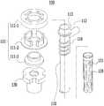
도 3은 본 발명의 일 실시예에 따른 삽입관을 나타내는 사시도이다.
도 4는 도 3에 도시된 삽입관을 나타내는 분해 조립도이다.
도 5는 도 3에 도시된 삽입관을 나타내는 정면도이다.
도 6은 본 발명의 일 실시예에 따른 삽입관이 절개부위를 통해 수술부위 내부로 삽입된 상태를 나타내는 단면 모식도이다.
도 7은 본 발명의 일 실시예에 다른 삽입관이 절개부위를 통해 수술부위 내부로 삽입된 후 볼팅체결 팽윤부의 형상 변형에 의해 안정적으로 고정된 모습을 나타내는 단면 모식도이다.
도 8은 본 발명의 또 다른 실시예에 따른 밀봉부를 나타내는 단면도이다.
도 9는 본 발명의 또 다른 실시예에 따른 삽입관 본체부의 분리된 구조를 나타내는 정면도이다.
도 10은 본 발명의 또 다른 실시예에 따른 볼팅체결 팽윤부를 나타내는 단면도이다.
도 11은 본 발명의 또 다른 실시예에 따른 볼팅체결부를 나타내는 단면도이다.1 is a perspective view showing a cannula according to the prior art.
Figure 2 is a schematic cross-sectional view showing a state in which the cannula according to the prior art is mounted on the surgical site.
3 is a perspective view showing an insertion tube according to an embodiment of the present invention.
4 is an exploded view illustrating the insertion tube illustrated in FIG. 3.
5 is a front view showing the insertion tube shown in FIG.
Figure 6 is a schematic cross-sectional view showing a state in which the insertion tube is inserted into the surgical site through the incision site according to an embodiment of the present invention.
Figure 7 is a schematic cross-sectional view showing a state in which the insertion tube is inserted into the surgical site through the incision in the embodiment of the present invention and stably fixed by the shape deformation of the bolting fastening swelling.
8 is a cross-sectional view showing a sealing part according to still another embodiment of the present invention.
Figure 9 is a front view showing a separated structure of the insertion tube body portion according to another embodiment of the present invention.
10 is a cross-sectional view showing a bolting fastening swelling portion according to another embodiment of the present invention.
11 is a cross-sectional view showing the bolting fastening according to another embodiment of the present invention.
이하 도면을 참조하여 본 발명의 바람직한 실시예를 상세히 설명하기로 한다. 이에 앞서, 본 명세서 및 청구범위에 사용된 용어나 단어는 통상적이거나 사전적인 의미로 한정하여 해석되어서는 아니되며, 본 발명의 기술적 사상에 부합하는 의미와 개념으로 해석되어야 한다.Hereinafter, exemplary embodiments of the present invention will be described in detail with reference to the accompanying drawings. Prior to this, the terms or words used in the present specification and claims should not be construed as being limited to ordinary or dictionary meanings, but should be construed as meanings and concepts consistent with the technical spirit of the present invention.
본 명세서 전체에서, 어떤 부재가 다른 부재 "상에" 위치하고 있다고 할 때, 이는 어떤 부재가 다른 부재에 접해 있는 경우뿐 아니라 두 부재 사이에 또 다른 부재가 존재하는 경우도 포함한다.본 명세서 전체에서, 어떤 부분이 어떤 구성요소를 "포함" 한다고 할 때, 이는 특별히 반대되는 기재가 없는 한 다른 구성요소를 제외하는 것이 아니라 다른 구성 요소를 더 포함할 수 있는 것을 의미한다.Throughout this specification, when a member is located "on" another member, this includes not only when one member is in contact with another member but also when another member exists between the two members. Throughout this specification, when a part is said to "include" a certain component, it means that it can further include other components, without excluding other components unless otherwise stated.
도 3에는 본 발명의 일 실시예에 따른 삽입관을 나타내는 사시도가 도시되어 있고, 도 4에는 도 3에 도시된 삽입관을 나타내는 분해 조립도가 도시되어 있다. 또한, 도 5에는 도 3에 도시된 삽입관을 나타내는 정면도가 도시되어 있고, 도 6에는 본 발명의 일 실시예에 따른 삽입관이 절개부위를 통해 수술부위 내부에 삽입된 상태를 나타내는 단면 모식도가 도시되어 있다.Figure 3 is a perspective view showing an insertion tube according to an embodiment of the present invention, Figure 4 is an exploded view of the insertion tube shown in Figure 3 is shown. In addition, Figure 5 is a front view showing the insertion tube shown in Figure 3, Figure 6 is a schematic cross-sectional view showing a state in which the insertion tube is inserted into the surgical site through the incision according to an embodiment of the present invention. Is shown.
이들 도면을 참조하면, 본 실시예에 따른 삽입관(100)은, 최소 침습수술에 적용되어 각종 수술도구를 절개부위를 통해 수술부위 내부에 삽입하거나, 수술 시행 시 수술부위에 에어나 물을 공급할 수 있는 삽입 통로를 제공하는 장치이다.Referring to these drawings, the
본 실시예에 따른 삽입관(100)은, 특정 구조의 삽입관 본체부(110), 볼팅체결 팽윤부(120) 및 볼팅체결부(130)를 구비함으로써, 절개부위 및 수술부위의 손상을 방지하고 이와 동시에 절개부위에 안정적으로 고정될 수 있으며, 역류되는 피의 누설을 최소한으로 방지할 수 있다. 또한, 본 실시예에 따른 삽입관(100)은, 도 5 및 도 6에 도시된 바와 같이, 볼팅체결부의 하방 위치 변경에 의해 안정적으로 직경이 증가하는 형태로 형상이 변형될 수 있으며, 결과적으로 수술부위에 안정적으로 밀착되어 삽입관 전체의 안정적인 고정을 보장할 수 있다.
이하에서는 도면을 참조하여, 본 실시예에 따른 삽입관(100)을 구성하는 각 구성에 대해 상세히 설명하기로 한다.Hereinafter, with reference to the drawings, each component constituting the
도 7에는 본 발명의 일 실시예에 다른 삽입관이 절개부위를 통해 수술부위 내부에 삽입된 후 볼팅체결 팽윤부의 형상 변형에 의해 안정적으로 고정된 모습을 나타내는 단면 모식도가 도시되어 있다.Figure 7 is a schematic cross-sectional view showing a state in which another insertion tube is stably fixed by the shape of the bolting fastening swelling part after being inserted into the surgical site through the incision in one embodiment of the present invention.
이들 도면을 참조하면, 본 실시예에 다른 삽입관 본체부(110)는, 일측에 바이패스 삽입구(112)가 형성되고, 일방향으로 소정 길이만큼 연장된 원통형 구조이다.Referring to these drawings, the insertion tube
도 3 및 도 4에 도시된 바와 같이, 본 실시예에 다른 삽입관 본체부(110)의 상단에는 밀봉부(111)가 장착될 수 있다.As shown in FIG. 3 and FIG. 4, the sealing
이때, 밀봉부(111)는, 수술 도구가 삽입될 수 있는 통로를 제공할 수있는 바, 수술 도구가 삽입되지 않은 상태 및 수술 도구가 삽입된 상태에서도 삽입관 본체부(110) 내측으로 연통되는 공간을 외부로부터 안정적으로 밀폐시킬 수 있다.At this time, the sealing
구체적으로, 본 실시예에 따른 밀봉부(111)의 하단에는 삽입관 본체부(110)와 결속되는 결속구조(113)가 형성됨이 바람직하다. 또한, 밀봉부(111)의 상단 내측에는 씰링부재 수용공간이 형성될 수 있다.Specifically, the lower end of the sealing
이때, 도 8에 도시된 바와 같이, 밀봉부(111)는 서로 결속 체결되는 상부(111-1), 하부(111-2)의 결속 구조에 의해 조립되는 구조로서, 삽입관 본체부(110)의 상단부와 결속되기 위한 연결부(111-3)가 추가로 조립된 구조일 수 있다. 이때, 연결부(111-3)는 하부(11-2)와 삽입관 본체부(110)의 상단부와 밀봉 결합될 수 있도록 고무 소재로 구성될 수 있다.At this time, as shown in Figure 8, the sealing
또한, 상부(111-1) 내측에 형성된 공간(씰링부재 수용공간)에는 둘 이상의 씰링부재(114, 115)가 서로 면접촉하도록 인접하여 장착될 수 있다. 이때, 둘 이상의 씰링부재(114, 115) 각각의 중앙부에는, 외부로부터 진입하는 수술 도구에 의해 개방되는 절개부(114-1, 115-1)가 평면상으로 보았을 때 각각 서로 다른 위치에 형성됨이 바람직하다. 더욱 구체적으로, 둘 이상의 씰링부재(114, 115)에 형성된 절개부(114-1, 115-1) 각각의 위치는, 수술도구의 진입에 의해 개방되는 각각의 절개부(114-1, 115-1)가 서로 연통되도록, 평면상으로 보았을 때 소정 거리만큼 이격된 위치일 수 있다.In addition, two or
평면상으로 보았을 때 각각 서로 다른 위치에 형성된 절개부(114-1, 115-1)는 수술 도구에 의해 개방되지 않을 경우, 밀폐된 구조로서, 둘 이상의 씰링부재(114, 115)가 서로 면접촉하여 적층된 구조를 형성함으로써, 더욱 효과적인 밀봉을 구현할 수 있다.When viewed in plan view, the incisions 114-1 and 115-1 formed at different positions respectively are closed when they are not opened by a surgical tool, and two or
또한, 수술 도구에 의해 절개부(114-1, 115-1)가 개방될 경우, 개방된 절개부(114-1, 115-1)의 각 단부는 수술 도구의 측 외부면과 밀착됨으로써, 밀봉 상태를 안정적으로 유지할 수 있다.In addition, when the incisions 114-1 and 115-1 are opened by the surgical tool, each end of the open incisions 114-1 and 115-1 is in close contact with the side outer surface of the surgical tool, thereby sealing. The state can be kept stable.
경우에 따라서, 절개부(114-1, 115-1)의 평면상 형상은, 도 8에 도시된 구조에 한정되지 아니하고, 밀봉 상태를 안정적으로 유지할 수 있는 다양한 구조로 변경 가능함은 물론이다.In some cases, the planar shapes of the cutouts 114-1 and 115-1 are not limited to the structure shown in FIG. 8, but may be changed to various structures capable of stably maintaining the sealed state.
한편, 삽입관 본체부(110)의 외주면에는, 볼팅체결부(130)와 볼팅결합되는 나사산(116)이 상하방향으로 소정 길이만큼 형성될 수 있다.On the other hand, on the outer circumferential surface of the
본 실시예에서는 삽입관 본체부(110)와 볼팅체결부(130)의 결속 구조를 나사 구조로 제시하였으나, 볼팅체결부(130)의 상하방향 위치를 운용자의 의도에 따라 안정적으로 변경할 수 있는 결속 구조라면 이에 한정되지 아니하고 적절히 변경 가능하다.In this embodiment, the binding structure of the
경우에 따라서, 도 9에 도시된 바와 같이, 삽입관 본체부(110)의 나사산(116)이 형성된 부분과 볼팅체결 팽윤부(120)가 장착되는 부분은, 삽입관 본체부(110)로부터 탈부착이 가능한 구조로 분리된 구조일 수 있다.In some cases, as shown in FIG. 9, the portion where the
구체적으로, 볼팅체결부(130)와 볼팅체결 팽윤부(120)의 길이(L1, L2, L3, L4)를 변경한 다양한 사양의 분리된 구조를 수술 대상 환자에 따라 맞춤 제작할 수 있다.In detail, the separated structures having various specifications in which the lengths L1, L2, L3, and L4 of the bolting
이 경우, 수술 대상 환자에 따라 달라지는 수술부위에 적합한 길이로 제작된 삽입관을 구성할 수 있어, 수술 대상 환자의 수술부위에 최적화된 구조의 삽입관을 제공할 수 있다.In this case, it is possible to configure the insertion tube made of a length suitable for the surgical site that varies depending on the patient to be operated, it is possible to provide an insertion tube of the structure optimized for the surgical site of the patient to be operated.
한편, 본 실시예에 따른 볼팅체결 팽윤부(120)는, 삽입관 본체부(110)와 볼팅체결부(130)에 의해 상단과 하단이 고정될 수 있다.On the other hand, the bolting
또한, 볼팅체결 팽윤부(120)는, 삽입관 본체부(110)의 외주면을 따라 소정 길이만큼 연장되어 밀착하여 장착되고 볼팅체결부(130)의 하방 위치변경에 의해 직경이 증가하는 형태로 형상이 변형되는 구조일 수 있다.In addition, the bolting
본 실시예에 따른 볼팅체결 팽윤부(120)는, 도 7에 도시된 바와 같이, 형상 변형되어 볼팅체결부(130)와 함께 절개부위를 가압하여 안정적으로 고정할 수 있다. 이때, 절개부위의 내측면과 접촉되는 볼팅체결 팽윤부(120)의 외부면에는 소정 크기의 마찰력을 가지는 구조가 형성되어 더욱 안정적인 고정을 구현할 수 있다.As shown in FIG. 7, the bolting
이때, 본 실시예에 따른 볼팅체결 팽윤부(120)는, 볼팅체결부(130)의 하방 위치변경에 의해 볼팅체결 팽윤부(120)가 직경이 증가하는 형태로 변형될 수 있도록, 유연한 소재로 구성됨이 바람직하다.At this time, the bolting
경우에 따라서, 도 10에 도시된 바와 같이, 볼팅체결 팽윤부(120)의 외부면에 삽입관 본체부(110)의 길이방향과 평행한 방향으로 소정 길이만큼 연장된 구조의 관통구(121)가 외주면을 따라 다수 형성될 수 있다.In some cases, as shown in Figure 10, the through-
본 실시예에 따른 관통구(121)는 볼팅체결 팽윤부(120)의 형상 변형을 더욱 안정적으로 유도할 수 있는 구조로 형성됨이 바람직하다.The through
예를 들어 관통구(121)의 형상은 상방으로 폭이 넓어지는 역삼각형 구조 또는 사다리꼴 구조임이 바람직하다.For example, the shape of the through
또한, 도 10에 도시된 바와 같이, 볼팅체결 팽윤부(120)의 외부면에는 외주면을 따라 소정 깊이만큼 만입된 구조의 그루브(122)가 형성될 수 있다. 이 경우, 볼팅체결 팽윤부(120)는, 볼팅체결부(130)의 하방 위치변경에 의해 직경이 증가하는 형태로 변형되어 그루브(122) 부위에서 절곡되어 변형될 수 있다.In addition, as shown in FIG. 10, a
따라서, 이러한 구조를 포함하는 본 실시예에 따른 삽입관(100)은, 볼팅체결부의 하방 위치 변경에 의해 안정적으로 직경이 증가하는 형태로 형상이 변형될 수 있으며, 이때 변형된 구조가 수술부위와 밀착될 수 있어, 결과적으로 삽입관 전체의 안정적인 고정을 보장할 수 있다.Therefore, the
이때, 볼팅체결 팽윤부(120)가 직경이 증가하는 형태로 형상 변형되었을 때 상방을 향하는 외부면에는, 소정 크기의 마찰력을 가지는 마찰구조(123)가 형성되거나 마찰소재가 코팅되어, 더욱 안정적인 고정을 보장할 수 있다.At this time, when the bolted
한편, 본 실시예에 따른 볼팅체결부(130)는, 삽입관 본체부(110)의 외주면에 볼팅체결되어 장착되는 구성으로서, 볼팅 동작에 의해 하방으로 위치변경되어 볼팅체결 팽윤부(120)의 상단부의 위치를 하방으로 위치변경시킬 수 있다.On the other hand, the bolting
경우에 따라서, 볼팅체결부(130)의 하단부(131)는, 하방으로 폭이 넓어지는 구조일 수 있다. 이 경우, 볼팅체결부(130)의 하단부(131)는 수술부위와 면접촉하며 안정적으로 가압할 수 있어, 결과적으로 삽입관 전체의 안정적인 고정을 보장할 수 있다.In some cases, the
또한, 도 11에 도시된 바와 같이, 볼팅체결부의 하단부(131)에는, 볼팅체결부의 하단부(131)와 대응되는 폭으로 형성된 와셔(132)가 장착될 수 있다. 이 경우, 볼팅 회전 동작하는 볼팅체결부의 하단부(131)가 직접적으로 면접촉함으로써 수술부위의 손상을 방지할 수 있다.In addition, as shown in FIG. 11, a
이상의 본 발명의 상세한 설명에서는 그에 따른 특별한 실시예에 대해서만 기술하였다. 하지만 본 발명은 상세한 설명에서 언급되는 특별한 형태로 한정되는 것이 아닌 것으로 이해되어야 하며, 오히려 첨부된 청구범위에 의해 정의되는 본 발명의 정신과 범위 내에 있는 모든 변형물과 균등물 및 대체물을 포함하는 것으로 이해되어야 한다.In the foregoing detailed description of the invention, only specific embodiments thereof have been described. It is to be understood, however, that the present invention is not limited to the specific forms referred to in the description, but rather includes all modifications, equivalents and substitutions within the spirit and scope of the invention as defined by the appended claims. Should be.
즉, 본 발명은 상술한 특정의 실시예 및 설명에 한정되지 아니하며, 청구범위에서 청구하는 본 발명의 요지를 벗어남이 없이 본 발명이 속하는 기술 분야에서 통상의 지식을 가진 자라면 누구든지 다양한 변형 실시가 가능하며, 그와 같은 변형은 본 발명의 보호 범위 내에 있게 된다.That is, the present invention is not limited to the above specific embodiments and descriptions, and various modifications can be made by those skilled in the art without departing from the gist of the present invention as claimed in the claims. It is possible for such modifications to fall within the protection scope of the present invention.
100: 삽입관
110: 삽입관 본체부
111: 밀봉부
111-1: 상부
111-2: 하부
111-3: 연결부
112: 바이패스 삽입구
113: 결속구조
114: 씰링부재
114-1: 절개부
115: 씰링부재
115-1: 절개부
116: 나사산
120: 볼팅체결 팽윤부
121: 관통구
122: 그루브
123: 마찰구조
130: 볼팅체결부
131: 하단부
132: 와셔(washer)100: insertion tube
110: insertion tube main body
111: seal
111-1: Top
111-2: bottom
111-3: Connection
112: bypass insertion hole
113: binding structure
114: sealing member
114-1: Incision
115: sealing member
115-1: Incision
116: thread
120: bolting fastening swelling
121: through hole
122: groove
123: friction structure
130: bolting connection
131: lower part
132: washer
Claims (13)
Translated fromKorean상단에 밀봉부(111)가 장착되고, 일측에 바이패스 삽입구(112)가 형성되고, 일방향으로 소정 길이만큼 연장된 원통형 구조의 삽입관 본체부(110);
일단부는 삽입관 본체부(110)의 하단부에 고정되고, 타단부는 볼팅체결부(130)의 하단부에 고정되며, 삽입관 본체부(110)의 외주면을 따라 소정 길이만큼 연장되어 밀착하여 장착되고 볼팅체결부(130)의 하방 위치변경에 의해 직경이 증가하는 형태로 형상 변형되는 볼팅체결 팽윤부(120); 및
상기 삽입관 본체부(110)의 외주면에 볼팅체결되어 장착되고, 볼팅 동작에 의해 하방으로 위치변경되어 볼팅체결 팽윤부(120)의 상단부의 위치를 하방으로 위치변경시키는 볼팅체결부(130);
를 포함하고,
상기 볼팅체결 팽윤부(120)의 외부면에는 삽입관 본체부(110)의 길이방향과 평행한 방향으로 소정 길이만큼 연장된 구조의 관통구(121)가 외주면을 따라 다수 형성되고, 상기 관통구(121)는, 상방으로 폭이 넓어지는 역삼각형 구조 또는 사다리꼴 구조이며,
상기 볼팅체결 팽윤부(120)의 외부면 중심 높이에는 외주면을 따라 소정 깊이만큼 만입된 구조의 그루브(122)가 형성되어 있고,
상기 볼팅체결 팽윤부(120)는, 볼팅체결부(130)의 하방 위치변경에 의해 직경이 증가하는 형태로 형상 변형되어 그루브(122) 부위에서 절곡되어 상부와 하부가 서로 맞닿아 접혀지는 것을 특징으로 하는 삽입관.
As an insertion tube 100 applied to minimally invasive surgery, various surgical tools are inserted into the surgical site through the incision site, or provide an insertion path for supplying air or water to the surgical site during surgery.
A seal 111 mounted at an upper end thereof, and a bypass insertion hole 112 is formed at one side thereof, and an insertion tube body 110 having a cylindrical structure extending in a direction by a predetermined length;
One end is fixed to the lower end of the insertion tube main body 110, the other end is fixed to the lower end of the bolting fastening portion 130, extends by a predetermined length along the outer circumferential surface of the insertion tube main body 110 is mounted in close contact with A bolting fastening swelling part 120 that is deformed in a shape in which the diameter is increased by changing a downward position of the bolting fastening part 130; And
A bolting fastening part 130 mounted on an outer circumferential surface of the insertion tube main body part 110 and shifted downward by a bolting operation to change the position of the upper end of the bolting fastening swelling part 120 downward;
Including,
The outer surface of the bolted fastening swelling portion 120 is formed with a plurality of through holes 121 of the structure extending by a predetermined length in a direction parallel to the longitudinal direction of the insertion tube main body 110, the through hole (121) is an inverted triangle structure or trapezoidal structure that widens upward,
A groove 122 having a structure indented by a predetermined depth along the outer circumferential surface is formed at the center height of the outer surface of the bolted fastening swelling part 120.
The bolting fastening swelling part 120 is deformed into a shape in which the diameter is increased by changing the lower position of the bolting fastening part 130 is bent in the groove 122, characterized in that the top and bottom are folded in contact with each other. Insertion tube made.
상기 밀봉부(111)의 하단에는 삽입관 본체부(100)와 결속되는 결속구조가 형성되고,
상기 밀봉부(111)의 상단 내측에는 씰링부재 수용공간이 형성된 것을 특징으로 하는 삽입관.
The method of claim 1,
The lower end of the sealing portion 111 is formed with a binding structure that is engaged with the insertion tube main body 100,
Insertion tube, characterized in that the sealing member receiving space is formed inside the upper end of the sealing portion (111).
상기 씰링부재 수용공간에는 둘 이상의 씰링부재(114, 115)가 서로 면접촉하도록 인접하여 장착되고,
상기 둘 이상의 씰링부재(114, 115) 각각의 중앙부에는, 외부로부터 진입하는 수술도구에 의해 개방되는 절개부(114-1, 115-1)가 평면상으로 보았을 때 각각 서로 다른 위치에 형성된 것을 특징으로 하는 삽입관.
The method of claim 2,
Two or more sealing members 114 and 115 are adjacently mounted in the sealing member accommodating space so as to be in surface contact with each other.
In the central portion of each of the two or more sealing members (114, 115), the incisions (114-1, 115-1) opened by the surgical instruments entering from the outside are formed in different positions when viewed in plan view Insertion tube made.
상기 둘 이상의 씰링부재(114, 115)에 형성된 절개부(114-1, 115-1) 각각의 위치는, 수술도구의 진입에 의해 개방되는 각각의 절개부(114-1, 115-1)가 서로 연통되도록, 평면상으로 보았을 때 소정 거리만큼 이격된 위치인 것을 특징으로 하는 삽입관.
The method of claim 3, wherein
The position of each of the cutouts 114-1 and 115-1 formed in the two or more sealing members 114 and 115 is such that each of the cutouts 114-1 and 115-1 opened by the entry of the surgical tool is provided. Insertion tube, characterized in that the position spaced apart by a predetermined distance in plan view so as to communicate with each other.
상기 삽입관 본체부(110)의 외주면에는, 볼팅체결부(130)와 볼팅결합되는 나사산(116)이 상하방향으로 소정 길이만큼 형성된 것을 특징으로 하는 삽입관.
The method of claim 1,
Insertion tube, characterized in that formed on the outer circumferential surface of the insertion tube main body portion 110 is a screw thread 116 bolted to the bolting fastening portion 130 in a vertical direction by a predetermined length.
상기 삽입관 본체부(110)의 나사산(116)이 형성된 부분과 볼팅체결 팽윤부(120)가 장착되는 부분은, 삽입관 본체부(110)로부터 탈부착이 가능한 구조로 분리된 구조인 것을 특징으로 하는 삽입관.
The method of claim 5,
The portion in which the screw thread 116 is formed and the portion in which the bolting fastening swelling portion 120 is mounted is inserted into the insertion tube main body 110 in a structure that is detachable from the insertion tube main body 110. Insert tube made.
상기 볼팅체결 팽윤부(120)는, 유연한 소재로 구성되고,
상기 볼팅체결 팽윤부(120)의 외부면은 소정 크기의 마찰력을 가지는 구조인 것을 특징으로 하는 삽입관.
The method of claim 1,
The bolting fastening swelling unit 120 is made of a flexible material,
Insertion tube, characterized in that the outer surface of the bolted fastening swelling portion 120 has a structure of a frictional force of a predetermined size.
상기 볼팅체결 팽윤부(120)가 직경이 증가하는 형태로 형상 변형되었을 때 상방을 향하는 외부면에는, 소정 크기의 마찰력을 가지는 마찰구조(123)가 형성되거나 마찰소재가 코팅되어 있는 것을 특징으로 하는 삽입관.
The method of claim 1,
When the bolting fastening swelling part 120 is deformed in the shape of increasing diameter, the outer surface facing upward, the friction structure 123 having a frictional force of a predetermined size is formed or the friction material is coated Insertion tube.
상기 볼팅체결부의 하단부(131)는 하방으로 폭이 넓어지는 구조인 것을 특징으로 하는 삽입관.
The method of claim 1,
The lower end portion 131 of the bolting fastening portion is inserted tube, characterized in that the structure is widened downward.
상기 볼팅체결부의 하단부(131)에는, 볼팅체결부의 하단부(131)와 대응되는 폭으로 형성된 와셔(132)가 장착되는 것을 특징으로 하는 삽입관.
The method of claim 12,
Insertion pipe, characterized in that the lower end 131 of the bolting fastening portion, the washer 132 formed with a width corresponding to the lower end 131 of the bolting fastening portion is mounted.
Priority Applications (1)
| Application Number | Priority Date | Filing Date | Title |
|---|---|---|---|
| KR1020180001899AKR102067561B1 (en) | 2018-01-05 | 2018-01-05 | Cannula Having Bolting Expansion Part |
Applications Claiming Priority (1)
| Application Number | Priority Date | Filing Date | Title |
|---|---|---|---|
| KR1020180001899AKR102067561B1 (en) | 2018-01-05 | 2018-01-05 | Cannula Having Bolting Expansion Part |
Publications (2)
| Publication Number | Publication Date |
|---|---|
| KR20190083900A KR20190083900A (en) | 2019-07-15 |
| KR102067561B1true KR102067561B1 (en) | 2020-01-17 |
Family
ID=67257837
Family Applications (1)
| Application Number | Title | Priority Date | Filing Date |
|---|---|---|---|
| KR1020180001899AActiveKR102067561B1 (en) | 2018-01-05 | 2018-01-05 | Cannula Having Bolting Expansion Part |
Country Status (1)
| Country | Link |
|---|---|
| KR (1) | KR102067561B1 (en) |
Families Citing this family (1)
| Publication number | Priority date | Publication date | Assignee | Title |
|---|---|---|---|---|
| CN114732508B (en)* | 2022-04-19 | 2025-01-28 | 河北瑞鹤医疗器械有限公司 | A fixed needle-guided point reduction forceps |
Citations (3)
| Publication number | Priority date | Publication date | Assignee | Title |
|---|---|---|---|---|
| KR101037617B1 (en)* | 2010-08-17 | 2011-05-30 | (주)다림써지넷 | Trocar with diameter extension release prevention means |
| JP2012522623A (en)* | 2009-04-06 | 2012-09-27 | アルファテック スパイン, インコーポレイテッド | Expandable spinal support device with attachable member and method of use thereof |
| KR101391680B1 (en)* | 2006-10-11 | 2014-05-07 | 에디컨 엔도-서저리 인코포레이티드 | Trocar seal with retraction induced hinge |
Family Cites Families (1)
| Publication number | Priority date | Publication date | Assignee | Title |
|---|---|---|---|---|
| KR20170039896A (en) | 2015-10-02 | 2017-04-12 | 재단법인 아산사회복지재단 | Cannular for secure of visual field of wide angle |
- 2018
- 2018-01-05KRKR1020180001899Apatent/KR102067561B1/enactiveActive
Patent Citations (3)
| Publication number | Priority date | Publication date | Assignee | Title |
|---|---|---|---|---|
| KR101391680B1 (en)* | 2006-10-11 | 2014-05-07 | 에디컨 엔도-서저리 인코포레이티드 | Trocar seal with retraction induced hinge |
| JP2012522623A (en)* | 2009-04-06 | 2012-09-27 | アルファテック スパイン, インコーポレイテッド | Expandable spinal support device with attachable member and method of use thereof |
| KR101037617B1 (en)* | 2010-08-17 | 2011-05-30 | (주)다림써지넷 | Trocar with diameter extension release prevention means |
Also Published As
| Publication number | Publication date |
|---|---|
| KR20190083900A (en) | 2019-07-15 |
Similar Documents
| Publication | Publication Date | Title |
|---|---|---|
| US11471026B2 (en) | System for a minimally-invasive, operative gastrointestinal treatment | |
| JP7048861B2 (en) | Intraluminal minimally invasive treatment system | |
| CN101836874B (en) | Flexible port seal | |
| US8480657B2 (en) | Detachable distal overtube section and methods for forming a sealable opening in the wall of an organ | |
| US9827009B2 (en) | Atraumatic arthroscopic instrument sheath | |
| US9084628B2 (en) | Endoluminal and transluminal surgical methods and devices | |
| US8663271B2 (en) | In-dwelling port for access into a body | |
| US20080108871A1 (en) | Vacuum stabilized overtube for endoscopic surgery | |
| US20070282266A1 (en) | Bifurcated endoscopy cannula | |
| EP2868259B1 (en) | Vaginal endoscopic port unit module | |
| EP2228016A1 (en) | Access port including multi-layer seal and suture parks | |
| US8740784B2 (en) | Rigidizable endoluminal access device | |
| US20100210912A1 (en) | Access port with suture management system including flapper with inserts | |
| KR102067561B1 (en) | Cannula Having Bolting Expansion Part | |
| US20100198018A1 (en) | Suture management system for surgical portal apparatus including internal tubes | |
| JP5912473B2 (en) | Micro Snake Retractor | |
| EP3656282A1 (en) | System for a minimally-invasive, operative gastrointestinal treatment | |
| US12376737B1 (en) | Tissue retractor for minimally invasive surgery | |
| JP2022033707A (en) | Flexible cannula having selective rigidity |
Legal Events
| Date | Code | Title | Description |
|---|---|---|---|
| A201 | Request for examination | ||
| PA0109 | Patent application | Patent event code:PA01091R01D Comment text:Patent Application Patent event date:20180105 | |
| PA0201 | Request for examination | ||
| E902 | Notification of reason for refusal | ||
| PE0902 | Notice of grounds for rejection | Comment text:Notification of reason for refusal Patent event date:20190605 Patent event code:PE09021S01D | |
| PG1501 | Laying open of application | ||
| E701 | Decision to grant or registration of patent right | ||
| PE0701 | Decision of registration | Patent event code:PE07011S01D Comment text:Decision to Grant Registration Patent event date:20191226 | |
| GRNT | Written decision to grant | ||
| PR0701 | Registration of establishment | Comment text:Registration of Establishment Patent event date:20200113 Patent event code:PR07011E01D | |
| PR1002 | Payment of registration fee | Payment date:20200114 End annual number:3 Start annual number:1 | |
| PG1601 | Publication of registration | ||
| PR1001 | Payment of annual fee | Payment date:20221228 Start annual number:4 End annual number:4 | |
| PR1001 | Payment of annual fee | Payment date:20240115 Start annual number:5 End annual number:5 | |
| PR1001 | Payment of annual fee | Payment date:20250113 Start annual number:6 End annual number:6 |