KR102066506B1 - Removal device for bundle of ship compressor - Google Patents
Removal device for bundle of ship compressorDownload PDFInfo
- Publication number
- KR102066506B1 KR102066506B1KR1020130109615AKR20130109615AKR102066506B1KR 102066506 B1KR102066506 B1KR 102066506B1KR 1020130109615 AKR1020130109615 AKR 1020130109615AKR 20130109615 AKR20130109615 AKR 20130109615AKR 102066506 B1KR102066506 B1KR 102066506B1
- Authority
- KR
- South Korea
- Prior art keywords
- bundle
- cradle
- compressor
- longitudinal direction
- tow bar
- Prior art date
- Legal status (The legal status is an assumption and is not a legal conclusion. Google has not performed a legal analysis and makes no representation as to the accuracy of the status listed.)
- Active
Links
- 238000000034methodMethods0.000claimsdescription5
- 230000002093peripheral effectEffects0.000claimsdescription2
- 238000009434installationMethods0.000description7
- 238000012423maintenanceMethods0.000description4
- 238000000926separation methodMethods0.000description3
- 238000010586diagramMethods0.000description2
- 230000000694effectsEffects0.000description2
- 238000005516engineering processMethods0.000description2
- 230000007423decreaseEffects0.000description1
- 230000005611electricityEffects0.000description1
- 238000004804windingMethods0.000description1
Images


Classifications
- B—PERFORMING OPERATIONS; TRANSPORTING
- B63—SHIPS OR OTHER WATERBORNE VESSELS; RELATED EQUIPMENT
- B63B—SHIPS OR OTHER WATERBORNE VESSELS; EQUIPMENT FOR SHIPPING
- B63B73/00—Building or assembling vessels or marine structures, e.g. hulls or offshore platforms
- B63B73/60—Building or assembling vessels or marine structures, e.g. hulls or offshore platforms characterised by the use of specific tools or equipment; characterised by automation, e.g. use of robots
- B—PERFORMING OPERATIONS; TRANSPORTING
- B21—MECHANICAL METAL-WORKING WITHOUT ESSENTIALLY REMOVING MATERIAL; PUNCHING METAL
- B21D—WORKING OR PROCESSING OF SHEET METAL OR METAL TUBES, RODS OR PROFILES WITHOUT ESSENTIALLY REMOVING MATERIAL; PUNCHING METAL
- B21D37/00—Tools as parts of machines covered by this subclass
- B21D37/04—Movable or exchangeable mountings for tools
- B—PERFORMING OPERATIONS; TRANSPORTING
- B63—SHIPS OR OTHER WATERBORNE VESSELS; RELATED EQUIPMENT
- B63B—SHIPS OR OTHER WATERBORNE VESSELS; EQUIPMENT FOR SHIPPING
- B63B73/00—Building or assembling vessels or marine structures, e.g. hulls or offshore platforms
- B63B73/20—Building or assembling prefabricated vessel modules or parts other than hull blocks, e.g. engine rooms, rudders, propellers, superstructures, berths, holds or tanks
- B—PERFORMING OPERATIONS; TRANSPORTING
- B63—SHIPS OR OTHER WATERBORNE VESSELS; RELATED EQUIPMENT
- B63B—SHIPS OR OTHER WATERBORNE VESSELS; EQUIPMENT FOR SHIPPING
- B63B73/00—Building or assembling vessels or marine structures, e.g. hulls or offshore platforms
- B63B73/40—Building or assembling vessels or marine structures, e.g. hulls or offshore platforms characterised by joining methods
- B—PERFORMING OPERATIONS; TRANSPORTING
- B63—SHIPS OR OTHER WATERBORNE VESSELS; RELATED EQUIPMENT
- B63B—SHIPS OR OTHER WATERBORNE VESSELS; EQUIPMENT FOR SHIPPING
- B63B81/00—Repairing or maintaining vessels
- B—PERFORMING OPERATIONS; TRANSPORTING
- B63—SHIPS OR OTHER WATERBORNE VESSELS; RELATED EQUIPMENT
- B63H—MARINE PROPULSION OR STEERING
- B63H21/00—Use of propulsion power plant or units on vessels
- B63H21/12—Use of propulsion power plant or units on vessels the vessels being motor-driven
- B63H21/14—Use of propulsion power plant or units on vessels the vessels being motor-driven relating to internal-combustion engines
- Y—GENERAL TAGGING OF NEW TECHNOLOGICAL DEVELOPMENTS; GENERAL TAGGING OF CROSS-SECTIONAL TECHNOLOGIES SPANNING OVER SEVERAL SECTIONS OF THE IPC; TECHNICAL SUBJECTS COVERED BY FORMER USPC CROSS-REFERENCE ART COLLECTIONS [XRACs] AND DIGESTS
- Y02—TECHNOLOGIES OR APPLICATIONS FOR MITIGATION OR ADAPTATION AGAINST CLIMATE CHANGE
- Y02T—CLIMATE CHANGE MITIGATION TECHNOLOGIES RELATED TO TRANSPORTATION
- Y02T70/00—Maritime or waterways transport
- Y02T70/10—Measures concerning design or construction of watercraft hulls
Landscapes
- Engineering & Computer Science (AREA)
- Chemical & Material Sciences (AREA)
- Combustion & Propulsion (AREA)
- Mechanical Engineering (AREA)
- Ocean & Marine Engineering (AREA)
- Architecture (AREA)
- Structural Engineering (AREA)
- Robotics (AREA)
- Manufacture Of Motors, Generators (AREA)
Abstract
Translated fromKoreanDescription
Translated fromKorean본 발명은 선박 압축기용 번들의 제거장치에 관한 것으로, 특히 압축기 스테이터 내에서 번들을 외부로 인출하기 위한 설비의 인출동작이 크레이들 상에서 이루어지도록 함으로써, 공간을 효율적으로 활용할 수 있도록 함과 아울러, 번들의 인출 설비를 단순 구성으로 구성하여 설비의 설치 비용을 절감할 수 있도록 그 구조가 개선된 선박 압축기용 번들의 제거장치에 관한 것이다.The present invention relates to an apparatus for removing a bundle for a ship compressor, and in particular, by making the take out operation of a facility for taking out the bundle to the outside in the compressor stator to be made on the cradle, the space can be utilized efficiently, and the bundle The apparatus for removing a bundle for a ship compressor with improved structure to reduce the installation cost of the facility by configuring the take-out facility in a simple configuration.
일반적으로, 선박은 엔진의 구동력을 이동하여 프로펠러를 회전시킴으로써 추진력을 얻게 되며, 발전기 등을 구동시킴으로써 필요한 전기를 얻게 된다. 한편, 선박의 엔진, 예컨대 디젤 엔진의 경우 스타트(Start)시 고압의 압축 에어를 필요로 하며, 이로 인해 선박에는 압축 에어를 엔진으로 공급하기 위한 스타팅 에어(Starting air)공급 시스템이 마련된다.In general, a ship obtains a driving force by moving the driving force of the engine to rotate the propeller, and obtains the necessary electricity by driving a generator or the like. On the other hand, a ship's engine, such as a diesel engine, requires high pressure compressed air at the start, and the ship is provided with a starting air supply system for supplying compressed air to the engine.
종래의 선박에 마련된 스타팅 에어 공급 시스템은 에어 콤프레셔(Air compressor)를 이용하여 엔진에 30bar 정도의 압력을 가진 압축 에어를 엔진의 실린더 내부에 공급하게 된다.The starting air supply system provided in the conventional vessel supplies an compressed air having a pressure of about 30 bar to the engine using an air compressor inside the cylinder of the engine.
한편, 선박용 압축기 스테이터 내에 삽입된 번들을 보수 및 교체 작업시 외부로 인출하여 제거하는 장치는 도 1에 도시된 바와 같이, 압축기 스테이터(10)의 내부에 삽입되어 있는 번들(20)을 수평 방향으로 인출하기 위해 번들(20)의 전면 하부에 크레이들(cradle;100)이 배치되고, 번들(20)의 일측과 이격되게 배치되고 번들(20)의 일측에 견인 와이어(40)를 매개로 연결되어 상기 번들(20)을 수평 길이방향으로 당겨서 압축기 스테이터(10)로부터 분리시키기 위한 풀링 포스트(50)로 구성된다.On the other hand, the apparatus for withdrawing and removing the bundle inserted into the compressor compressor stator to the outside during the maintenance and replacement operation, as shown in Figure 1, the
또한, 번들(20)이 분리되는 동안 지지하기 위해 번들(20)의 이동 경로 상측에 모노레일(30)과 호이스트(35)가 배치되어 있다.In addition, the
이러한 기존 압축기 스테이터(10)와 번들(20)의 분리작업은 견인 와이어(40)를 풀링 포스트(50)에 연결한 상태에서 견인 와이어(40)를 당겨서 번들(20)을 크레이들(100) 상측에 안착시킨 후에, 호이스트(35)를 모노레일(30)을 따라 이동시키면서 번들(20)을 압축기 스테이터(10)로부터 완전히 분리시키는 과정을 갖는다.The separation operation of the existing
또한, 앞서 설명한 압축기의 번들이 아닌 열교환기의 번들을 외부로 인출하는 기술과 관련된 기술은 한국 공개특허공보 공개번호 제 10-2011-0051454호 "해상구조물의 열교환기 유지보수 장치 및 방법"(공개일자 : 2011.05.18)에 기재된 바와 같이, 열교환기로부터 상기 튜브 번들을 일방향으로 당겨 분리시키도록 배치된 풀링 포스트와; 상기 튜브 번들이 분리되는 동안, 상기 튜브 번들을 들어 지탱하도록 배치된 호이스트와; 천장에 설치되어 상기 튜브 번들의 분리 방향과 평행하게 상기 호이스트를 안내하는 모노레일을 포함한 것이다.In addition, the technology related to the technology of drawing out the bundle of the heat exchanger to the outside, not the bundle of the compressor described above is disclosed in Korean Patent Laid-Open Publication No. 10-2011-0051454 "Heat exchanger maintenance apparatus and method of the offshore structure" (Publication Date: 2011.05.18), a pulling post arranged to pull the tube bundle in one direction to separate it from the heat exchanger; A hoist arranged to lift and support the tube bundle while the tube bundle is separated; It includes a monorail installed on the ceiling to guide the hoist parallel to the separation direction of the tube bundle.
그런데, 기존 번들의 제거를 위한 장치는 풀링 포스트가 크레이들로부터 이격된 위치에 배치되어야 하며, 상측에 모노레일 및 호이스트가 요구되므로, 설비의 설치 및 자재비용으로 인해 부품단가 상승 요인이 되며, 넓은 공간이 요구되어 공간활용성이 저하되고 설치공간의 제약을 갖는다.By the way, the device for removing the existing bundle should be placed in a position in which the pulling post is spaced apart from the cradle, and a monorail and a hoist are required on the upper side, which increases the cost of parts due to the installation and material cost of the equipment, and a large space. This demand decreases the space utilization and has a limitation of the installation space.
본 발명은 상기한 제반문제점을 감안하여 이를 해결하고자 창출된 것으로, 그 목적은 단순 구성으로 압축기 스테이터 내에 삽입된 번들을 외부로 인출시켜 제거할 수 있도록 함과 아울러, 비용 절감 및 공간 활용성을 향상시킬 수 있도록 그 구조가 개선된 선박 압축기용 번들의 제거장치를 제공하는 데 있다.The present invention has been made in view of the above-mentioned problems, and the object thereof is to allow the bundle inserted in the compressor stator to be taken out to be removed to the outside with a simple configuration, and to reduce costs and improve space utilization. The present invention provides an apparatus for removing a bundle for a ship compressor, the structure of which is improved.
상기한 목적을 달성하기 위한 본 발명은 압축기 스테이터의 내부에 결합된 번들을 수평 방향으로 인출하도록 상기 번들의 하측에 배치되는 크레이들과;The present invention for achieving the above object is a cradle disposed on the lower side of the bundle to withdraw the bundle coupled to the interior of the compressor stator in the horizontal direction;
상기 크레이들의 상측에 탑재되고 상기 번들의 일측에 견인봉을 매개로 연결되어 상기 견인봉을 매개로 상기 번들을 수평 길이방향으로 당겨서 압축기 스테이터로부터 분리시키기 위한 견인수단과;A towing means mounted on an upper side of the cradle and connected to one side of the bundle via a tow bar to pull the bundle in a horizontal longitudinal direction via the tow bar to separate from the compressor stator;
상기 번들의 하부를 지지하며 상기 크레이들의 상측에 길이방향으로 이동 가능하게 배치되어 상기 번들의 이동을 가이드하는 이동 가이드수단;을 구비한 것을 특징으로 한다.And a movement guide means for supporting a lower portion of the bundle and movably disposed in the longitudinal direction on the cradle to guide movement of the bundle.
상기 이동 가이드수단은 상기 크레이들의 상측에 길이방향으로 배치되는 가이드봉과,The moving guide means and the guide rod is disposed in the longitudinal direction on the cradle,
상기 분리된 번들이 안착되고 상기 가이드봉에 관통되어 길이방향으로 슬라이딩 이동되는 번들 서포트 블록을 구비한다.The separated bundle has a bundle support block which is seated and penetrates the guide rod and slides in the longitudinal direction.
상기 번들과 견인봉 사이에 배치되어 상기 번들의 얼라인먼트를 지지하는 얼라인먼트 서포트 블록을 더 구비한 것이다.It is further provided with an alignment support block disposed between the bundle and the drawbar to support the alignment of the bundle.
상기 얼라인먼트 서포트 블록은 일측 부위가 상기 번들의 내경 내주면에 고정되도록 결합되는 사각틀 구조로 형성된다.The alignment support block is formed in a rectangular frame structure in which one side portion is fixed to the inner diameter inner circumferential surface of the bundle.
상기 견인수단은 상기 크레이들의 상측에 탈 부착 가능하도록 배치되고 상기 견인봉이 관통되는 견인블록과,The towing means is disposed to be detachably attached to an upper side of the cradle, and a tow block through which the tow bar penetrates;
상기 견인블록에 회전 가능하게 탑재되고 회전 동작시 상기 견인봉을 당겨서 견인하는 견인핸들을 구비한다.It is rotatably mounted to the towing block and has a towing handle that pulls the tow bar during the rotation operation.
본 발명은 기존의 모노레일이나 호이스트 및 풀링 포스트 등의 설비 없이 번들을 압축기 스테이터로부터 외부로 인출시킬 수 있으므로, 설비의 설치 및 자재비용을 절감할 수 있을 뿐만 아니라, 모노레일이나 호이스트 풀리 포스트등의 장비가 생략되고 크레이들 상에서 번들의 인출작업이 이루어지게 됨에 따라 번들을 인출하기 위한 설비의 설치공간을 축소시켜 공간 활용성을 증대시킬 수 있는 유용한 효과를 갖는다.According to the present invention, the bundle can be pulled out from the compressor stator without any existing monorail, hoist, or pulling post, and thus, equipment installation and material cost can be reduced, and equipment such as monorail or hoist pulley post is provided. As it is omitted and the withdrawal operation of the bundle is made on the cradle has a useful effect that can reduce the installation space of the facility for withdrawing the bundle to increase the space utilization.
도 1은 기존 선박 압축기용 번들의 제거장치를 나타낸 구성도.
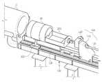
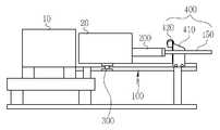
도 2는 본 발명에 따른 선박 압축기용 번들의 제거장치를 나타낸 사시도.
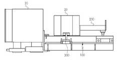
도 3은 도 2의 정면도.
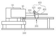
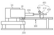
도 4a, 4b, 4c, 4d는 본 발명의 번들과 압축기 스테이터의 분리과정을 순차적으로 나타낸 사용상태도.1 is a block diagram showing an apparatus for removing a bundle for an existing ship compressor.
Figure 2 is a perspective view showing a removal device of the bundle for a ship compressor according to the present invention.
3 is a front view of FIG. 2;
Figure 4a, 4b, 4c, 4d is a state diagram showing the sequence of separation of the bundle and the compressor stator of the present invention.
본 발명은 압축기 스테이터 내에서 번들을 외부로 인출하기 위한 설비를 단순 구성으로 크레이들 상에서 인출작업이 이루어지도록 함으로써, 설비의 비용을 절감할 수 있으면서 공간 활용성을 향상시킬 수 있도록 한다.The present invention allows the facility for drawing out the bundle to the outside in the compressor stator to be withdrawn on the cradle in a simple configuration, thereby improving the space utilization while reducing the cost of the facility.
본 발명에 따른 선박 압축기용 번들의 제거장치는, 도 2 내지 도 4를 참조하면, 압축기 스테이터(10)의 내부에 결합된 번들(20)의 일측에 수평 방향으로 인출하도록 상기 번들(20)의 하측에 배치되는 크레이들(100)과; 상기 크레이들(100)의 상측에 탑재되고 상기 번들(20)의 일측에 견인봉(450)을 매개로 연결되어 상기 견인봉(450)을 매개로 상기 번들(20)을 수평 길이방향으로 당겨서 압축기 스테이터(10)로부터 분리시키기 위한 견인수단(400)과; 상기 번들(20)의 하부를 지지하며 상기 크레이들의 상측에 길이방향으로 이동 가능하게 배치되어 상기 번들(20)의 이동을 가이드하는 이동 가이드수단;으로 구성된다.The apparatus for removing a bundle for a ship compressor according to the present invention, referring to FIGS. 2 to 4, of the
도 2 및 도 3을 참조하면, 압축기 스테이터(10)의 내부에 삽입된 상태의 번들(20)을 수평 길이방향으로 인출하기 위해 크레이들(100)이 번들(20)보다 하측에 위치되도록 배치된다.2 and 3, the
또한, 견인수단(400)은 크레이들(100)의 상측에 탈 부착 가능하도록 배치되고 상기 견인봉(450)이 관통되는 견인블록(410)과, 상기 견인블록(410)에 회전 가능하게 탑재되고 회전 동작시 단부가 상기 견인봉(450)과 접촉됨에 따라 상기 견인봉(450)을 당겨서 견인할 수 있는 견인핸들(420)로 구성된다.In addition, the towing means 400 is disposed to be detachably attached to the upper side of the
한편, 견인수단(400)은 번들(20)의 일측에 견인 와이어가 연결되고, 모터의 구동력으로 견인 와이어를 감아서 수평으로 번들(20)을 외부 인출하는 윈치를 채용할 수도 있다.On the other hand, the traction means 400 may be a winch for connecting the traction wire to one side of the
상기 이동 가이드수단은 상기 크레이들(100)의 상측에 길이방향으로 배치되는 가이드봉(150)과, 상기 분리된 번들(20)이 안착되고 상기 가이드봉(150)에 관통되어 길이방향으로 슬라이딩 이동되는 번들 서포트 블록(300)으로 구성된다.The movement guide means is a
바람직하게는, 번들 서포트 블록(300)은 상부면이 번들(20)의 외주면 형상과 대응되는 원호형 구조를 갖는다.Preferably, the
또한, 본 발명은 번들(20)과 견인봉(450) 사이에 배치되어 상기 번들(20)의 얼라인먼트(alignment)를 지지하는 얼라인먼트 서포트 블록(200)을 더 구비하는 것이 바람직하다.In addition, the present invention preferably further includes an
상기 얼라인먼트 서포트 블록(200)은 사각틀 형태로 구성되고, 사각틀의 일측 부위가 상기 번들(20)의 내경 내주면에 고정되도록 결합된다.The
이러한 구성을 갖는 본 발명은 먼저, 도 4a에서와 같이, 번들(20)의 일측 하부에 크레이들(100)을 배치시키고, 크레이들(100)의 상측에 슬라이딩 가능하게 결합된 번들 서포트 블록(300)을 번들(20) 주위에 근접되도록 배치시킨다.In the present invention having such a configuration, as shown in FIG. 4A, the
그리고 번들(20)의 일측에 얼라인먼트 서포트 블록(200)의 일측 부위를 연결하고, 얼라인먼트 서포트 블록(200)의 타측에 견인봉(450)을 연결시킨다.Then, one side of the
이때, 견인봉(450)은 견인블록(410)에 관통되도록 결합되고, 견인핸들(420)의 회전동작에 따라 전,후로 이동 가능하게 연결시킨다.At this time, the
이어서, 견인핸들(420)을 회전시켜 견인봉(450)을 1차 견인시키면, 도 4b에서와 같이, 얼라인먼트 서포트 블록(200)과 연결된 번들(20)이 압축기 스테이터(10)로부터 일부위 인출되면서 번들 서포트 블록(300)상에 안착된다.Subsequently, when the
이후에 도 4c에서와 같이, 견인블록(410)을 크레이들(100)의 상측 임의의 위치에 고정시킨 후에 견인봉(450)을 견인시키면, 도 4d에서와 같이 번들(20)이 번들 서포트 블록(300)에 안착되어 지지된 상태로 크레이들(100)의 수평 길이방향으로 이동되어 압축기 스테이터(10)로부터 완전 분리된다.Thereafter, as shown in FIG. 4C, when the
이때, 번들 서포트 블록(300)은 가이드봉(150)에 의해 이동이 가이드된다.At this time, the
이로 인해, 본 발명은 번들(20)을 압축기 스테이터(10)의 내부에서 외부로 인출시킨 후에 보수작업을 수행하거나, 얼라인먼트 서포트 블록(200)과의 연결상태를 해제한 후에 크레인이나 별도의 장비를 이용하여 크레이들(100)로부터 이동시켜 외부의 임의 장소로 이전하여 폐기 처분할 수 있다.For this reason, the present invention performs the maintenance work after drawing the
따라서, 본 발명은 기존의 모노레일이나 호이스트 및 풀링 포스트 등의 설비 없이 번들(20)을 압축기 스테이터(10)로부터 외부로 인출시킬 수 있으므로, 설비의 설치비용을 절감할 수 있으며 설비의 설치공간을 축소시켜 공간 활용성을 증대시킬 수 있는 유용한 효과를 갖는다.Therefore, the present invention can withdraw the
10 : 압축기 스테이터 20 : 번들
100 : 크레이들 150 : 가이드봉
200 : 얼라인먼트 서포트 블록 300 : 번들 서포트 블록
400 : 견인수단 410 : 견인블록
420 : 견인핸들 450 : 견인봉10: compressor stator 20: bundle
100: cradle 150: guide rod
200: alignment support block 300: bundle support block
400: towing means 410: towing block
420: tow handle 450: tow bar
Claims (5)
Translated fromKorean상기 크레이들(100)의 상측에 탑재되고 상기 번들(20)의 일측에 견인봉(450)을 매개로 연결되어 상기 견인봉(450)을 매개로 상기 번들(20)을 수평 길이방향으로 당겨서 압축기 스테이터(10)로부터 분리시키기 위한 견인수단(400)과;
상기 번들(20)의 하부를 지지하며 상기 크레이들(100)의 상측에 길이방향으로 이동 가능하게 배치되어 상기 번들(20)의 이동을 가이드하는 이동 가이드수단;을 구비하며,
상기 이동 가이드수단은 상기 크레이들(100)의 상측에 길이방향으로 배치되는 가이드봉(150)과,
상기 분리된 번들(20)이 안착되고 상기 가이드봉(150)에 관통되어 길이방향으로 슬라이딩 이동되는 번들 서포트 블록(300)을 구비한 것을 특징으로 하는 선박 압축기용 번들의 제거장치.A cradle (100) disposed below the bundle (20) to pull out the bundle (20) coupled to the inside of the compressor stator (10) in a horizontal direction;
Mounted on the upper side of the cradle 100 and connected to one side of the bundle 20 via a tow bar 450, by pulling the bundle 20 in the horizontal longitudinal direction via the tow bar 450 compressor Towing means (400) for separating from the stator (10);
And a movement guide means for supporting a lower portion of the bundle 20 and being movable in the longitudinal direction on the cradle 100 to guide the movement of the bundle 20.
The moving guide means is a guide rod 150 disposed in the longitudinal direction on the cradle 100, and
The detached bundle 20 of the ship compressor, characterized in that the bundle is provided with a bundle support block 300 which is penetrated through the guide rod (150) and sliding in the longitudinal direction.
상기 번들(20)과 견인봉(450) 사이에 배치되어 상기 번들(20)의 얼라인먼트를 지지하는 얼라인먼트 서포트 블록(200)을 더 구비한 것을 특징으로 하는 선박 압축기용 번들의 제거장치.The method according to claim 1,
The apparatus of claim 1, further comprising an alignment support block (200) disposed between the bundle (20) and the tow bar (450) to support the alignment of the bundle (20).
상기 얼라인먼트 서포트 블록(200)은 일측 부위가 상기 번들(20)의 내경 내주면에 고정되도록 결합되는 사각틀 구조로 형성된 것을 특징으로 하는 선박 압축기용 번들의 제거장치.The method according to claim 3,
The alignment support block 200 is a ship compressor bundle removal device, characterized in that formed in a rectangular frame structure that is coupled to one side is fixed to the inner peripheral surface of the inner diameter of the bundle (20).
상기 견인수단(400)은 상기 크레이들(100)의 상측에 탈 부착 가능하도록 배치되고 상기 견인봉(450)이 관통되는 견인블록(410)과,
상기 견인블록(410)에 회전 가능하게 탑재되고 회전 동작시 상기 견인봉(450)을 당겨서 견인하는 견인핸들(420)을 구비한 것을 특징으로 하는 선박 압축기용 번들의 제거장치.The method according to any one of claims 1, 3 or 4,
The towing means 400 is disposed to be detachably attached to the upper side of the cradle 100 and the towing block 410 through which the tow bar 450 is penetrated;
And a traction handle (420) rotatably mounted to the traction block (410) and pulling the traction rod (450) to tow during the rotation operation.
Priority Applications (1)
| Application Number | Priority Date | Filing Date | Title |
|---|---|---|---|
| KR1020130109615AKR102066506B1 (en) | 2013-09-12 | 2013-09-12 | Removal device for bundle of ship compressor |
Applications Claiming Priority (1)
| Application Number | Priority Date | Filing Date | Title |
|---|---|---|---|
| KR1020130109615AKR102066506B1 (en) | 2013-09-12 | 2013-09-12 | Removal device for bundle of ship compressor |
Publications (2)
| Publication Number | Publication Date |
|---|---|
| KR20150030413A KR20150030413A (en) | 2015-03-20 |
| KR102066506B1true KR102066506B1 (en) | 2020-01-15 |
Family
ID=53024461
Family Applications (1)
| Application Number | Title | Priority Date | Filing Date |
|---|---|---|---|
| KR1020130109615AActiveKR102066506B1 (en) | 2013-09-12 | 2013-09-12 | Removal device for bundle of ship compressor |
Country Status (1)
| Country | Link |
|---|---|
| KR (1) | KR102066506B1 (en) |
Family Cites Families (4)
| Publication number | Priority date | Publication date | Assignee | Title |
|---|---|---|---|---|
| JPS59164123A (en)* | 1983-03-08 | 1984-09-17 | Sumitomo Heavy Ind Ltd | Molding processing equipment for plastic |
| JPS61149334A (en)* | 1984-12-25 | 1986-07-08 | Fanuc Ltd | Mold automatic replacing apparatus for injection molding machine |
| JPS6347119U (en)* | 1986-09-16 | 1988-03-30 | ||
| KR20110051454A (en) | 2009-11-10 | 2011-05-18 | 대우조선해양 주식회사 | Heat exchanger maintenance device and method of offshore structure |
- 2013
- 2013-09-12KRKR1020130109615Apatent/KR102066506B1/enactiveActive
Also Published As
| Publication number | Publication date |
|---|---|
| KR20150030413A (en) | 2015-03-20 |
Similar Documents
| Publication | Publication Date | Title |
|---|---|---|
| KR101471017B1 (en) | High tension cable multi pulling device | |
| CN107472992B (en) | Waste cable material separation and recovery device | |
| CN106115471A (en) | A kind of hanging apparatus of segmentation | |
| CN107492425B (en) | A kind of waste and old cable peeling recyclable device | |
| CN102839649B (en) | Automatic rammer hanging method of hooking device guided by cord | |
| CN105479628A (en) | Mould dismounting machine and mould dismounting method | |
| CN110311306B (en) | Intelligent distribution box | |
| CN111751201A (en) | Car wiring harness pulling force detection device | |
| CN107893569B (en) | Waste telegraph pole removing machine | |
| KR102066506B1 (en) | Removal device for bundle of ship compressor | |
| KR20120125231A (en) | Apparatus for Retracting, Storing and Inserting an Elongated Element | |
| CN110524067A (en) | Bar material-pulling device | |
| CN108213274B (en) | A kind of cutting equipment for cable | |
| CN205429673U (en) | Cable draw gear | |
| CN116388056B (en) | Traction machine for erecting electric iron tower wires and application method thereof | |
| CN202662493U (en) | Electromagnetic switch laying-off device | |
| CN106944976A (en) | A kind of frock and method that protective case is assembled on U-shaped bar | |
| CN215248658U (en) | Cable wire barrow | |
| CN207329567U (en) | With supporting mobile trolley used of bale splitter | |
| KR102559106B1 (en) | deconstruction cutting pulling apparatus of the underground power cable | |
| CN102779671B (en) | Electromagnetic switch discharging device | |
| CN212024612U (en) | Light engineering machinery suspension arm with multifunctional composite structure design | |
| CN210231030U (en) | Pay-off device for wire drawing machine | |
| CN104555563A (en) | Yarn arrangement device for carbon fiber yarn winder | |
| CN209097965U (en) | A kind of removable shore connection cable volume vehicle with telescopic arm |
Legal Events
| Date | Code | Title | Description |
|---|---|---|---|
| PA0109 | Patent application | Patent event code:PA01091R01D Comment text:Patent Application Patent event date:20130912 | |
| PG1501 | Laying open of application | ||
| A201 | Request for examination | ||
| PA0201 | Request for examination | Patent event code:PA02012R01D Patent event date:20180910 Comment text:Request for Examination of Application Patent event code:PA02011R01I Patent event date:20130912 Comment text:Patent Application | |
| E902 | Notification of reason for refusal | ||
| PE0902 | Notice of grounds for rejection | Comment text:Notification of reason for refusal Patent event date:20190620 Patent event code:PE09021S01D | |
| E701 | Decision to grant or registration of patent right | ||
| PE0701 | Decision of registration | Patent event code:PE07011S01D Comment text:Decision to Grant Registration Patent event date:20191126 | |
| GRNT | Written decision to grant | ||
| PR0701 | Registration of establishment | Comment text:Registration of Establishment Patent event date:20200109 Patent event code:PR07011E01D | |
| PR1002 | Payment of registration fee | Payment date:20200109 End annual number:3 Start annual number:1 | |
| PG1601 | Publication of registration | ||
| PR1001 | Payment of annual fee | Payment date:20221226 Start annual number:4 End annual number:4 | |
| PR1001 | Payment of annual fee | Payment date:20240108 Start annual number:5 End annual number:5 | |
| PR1001 | Payment of annual fee | Payment date:20241223 Start annual number:6 End annual number:6 |