KR102065419B1 - Clip type mobile terminal - Google Patents
Clip type mobile terminalDownload PDFInfo
- Publication number
- KR102065419B1 KR102065419B1KR1020130148428AKR20130148428AKR102065419B1KR 102065419 B1KR102065419 B1KR 102065419B1KR 1020130148428 AKR1020130148428 AKR 1020130148428AKR 20130148428 AKR20130148428 AKR 20130148428AKR 102065419 B1KR102065419 B1KR 102065419B1
- Authority
- KR
- South Korea
- Prior art keywords
- frame
- clip
- mobile terminal
- cover
- disposed
- Prior art date
- Legal status (The legal status is an assumption and is not a legal conclusion. Google has not performed a legal analysis and makes no representation as to the accuracy of the status listed.)
- Ceased
Links
Images


Classifications
- H—ELECTRICITY
- H04—ELECTRIC COMMUNICATION TECHNIQUE
- H04B—TRANSMISSION
- H04B1/00—Details of transmission systems, not covered by a single one of groups H04B3/00 - H04B13/00; Details of transmission systems not characterised by the medium used for transmission
- H04B1/38—Transceivers, i.e. devices in which transmitter and receiver form a structural unit and in which at least one part is used for functions of transmitting and receiving
- H04B1/3827—Portable transceivers
- H04B1/3888—Arrangements for carrying or protecting transceivers
- H—ELECTRICITY
- H04—ELECTRIC COMMUNICATION TECHNIQUE
- H04B—TRANSMISSION
- H04B1/00—Details of transmission systems, not covered by a single one of groups H04B3/00 - H04B13/00; Details of transmission systems not characterised by the medium used for transmission
- H04B1/38—Transceivers, i.e. devices in which transmitter and receiver form a structural unit and in which at least one part is used for functions of transmitting and receiving
- H04B1/3827—Portable transceivers
- H04B1/385—Transceivers carried on the body, e.g. in helmets
- H—ELECTRICITY
- H04—ELECTRIC COMMUNICATION TECHNIQUE
- H04M—TELEPHONIC COMMUNICATION
- H04M1/00—Substation equipment, e.g. for use by subscribers
- H04M1/02—Constructional features of telephone sets
- H04M1/0202—Portable telephone sets, e.g. cordless phones, mobile phones or bar type handsets
- H—ELECTRICITY
- H04—ELECTRIC COMMUNICATION TECHNIQUE
- H04B—TRANSMISSION
- H04B1/00—Details of transmission systems, not covered by a single one of groups H04B3/00 - H04B13/00; Details of transmission systems not characterised by the medium used for transmission
- H04B1/38—Transceivers, i.e. devices in which transmitter and receiver form a structural unit and in which at least one part is used for functions of transmitting and receiving
- H04B1/3827—Portable transceivers
- H04B1/385—Transceivers carried on the body, e.g. in helmets
- H04B2001/3855—Transceivers carried on the body, e.g. in helmets carried in a belt or harness
- H—ELECTRICITY
- H04—ELECTRIC COMMUNICATION TECHNIQUE
- H04M—TELEPHONIC COMMUNICATION
- H04M1/00—Substation equipment, e.g. for use by subscribers
- H04M1/02—Constructional features of telephone sets
- H04M1/0202—Portable telephone sets, e.g. cordless phones, mobile phones or bar type handsets
- H04M1/0249—Details of the mechanical connection between the housing parts or relating to the method of assembly
- H—ELECTRICITY
- H04—ELECTRIC COMMUNICATION TECHNIQUE
- H04M—TELEPHONIC COMMUNICATION
- H04M1/00—Substation equipment, e.g. for use by subscribers
- H04M1/02—Constructional features of telephone sets
- H04M1/0202—Portable telephone sets, e.g. cordless phones, mobile phones or bar type handsets
- H04M1/026—Details of the structure or mounting of specific components
- H04M1/0262—Details of the structure or mounting of specific components for a battery compartment
- H—ELECTRICITY
- H04—ELECTRIC COMMUNICATION TECHNIQUE
- H04M—TELEPHONIC COMMUNICATION
- H04M1/00—Substation equipment, e.g. for use by subscribers
- H04M1/02—Constructional features of telephone sets
- H04M1/0202—Portable telephone sets, e.g. cordless phones, mobile phones or bar type handsets
- H04M1/026—Details of the structure or mounting of specific components
- H04M1/0266—Details of the structure or mounting of specific components for a display module assembly
Landscapes
- Engineering & Computer Science (AREA)
- Signal Processing (AREA)
- Computer Networks & Wireless Communication (AREA)
- Telephone Set Structure (AREA)
- Casings For Electric Apparatus (AREA)
Abstract
Translated fromKorean
Description
Translated fromKorean본 발명은 이동 단말기에 관한 것으로, 보다 상세하게는 신체 및 물건의 다양한 부위에 간편하게 거치할 수 있는 클립형 이동 단말기에 관한 것이다.The present invention relates to a mobile terminal, and more particularly, to a clip-type mobile terminal that can be easily mounted on various parts of the body and objects.
단말기는, 이동 가능여부에 따라, 이동 단말기(mobile/portable terminal) 및 고정 단말기(stationary terminal)로 나뉠 수 있다.The terminal is movable Depending on whether it is, it can be divided into a mobile terminal (mobile / portable terminal) and a stationary terminal (stationary terminal).
그리고, 이동 단말기는, 사용자의 직접 휴대 가능 여부에 따라, 휴대(형) 단말기(handheld terminal) 및 거치형 단말기(vehicle mount terminal)로 나뉠 수 있다.In addition, the mobile terminal may be classified into a handheld terminal and a vehicle mount terminal according to whether a user can directly carry it.
이와 같은, 단말기(terminal)는 기능이 다양화됨에 따라, 예를 들어, 사진이나 동영상의 촬영, 음악이나 동영상 파일의 재생, 게임, 방송의 수신 등의 복합적인 기능들을 갖춘 멀티미디어 기기(Multimedia player) 형태로 구현되고 있다.As the terminal functions are diversified, for example, a multimedia player having complex functions such as photographing a picture or a video, playing a music or video file, playing a game, receiving a broadcast, etc. It is implemented in the form.
이동 단말기는, 그 구조 특성상, 신체나 물건 등에 거치할 수 없는 구조로 이루어져 있으므로, 사용자가 직접 손으로 잡고 사용하거나, 추가적인 거치 장치에 거치하여 사용할 수 밖에 없었다.Since the mobile terminal has a structure that cannot be mounted on a body or an object due to its structure, the user has to use the device by hand or mount it on an additional mounting device.
사용자가 직접 손으로 이동 단말기를 잡고 사용하거나, 또는 옷 주머니에 이동 단말기를 보관하여 사용하는 경우, 이동 단말기가 사용자의 손이나 옷 주머니로부터 쉽게 이탈되어 손상 및 분실의 위험이 높은 문제들이 있었다.When the user directly uses the mobile terminal by hand, or stores and uses the mobile terminal in a clothes pocket, the mobile terminal is easily detached from the user's hand or the pocket of clothes and there is a high risk of damage and loss.
또한, 사용자가 이동 단말기를 거치 장치에 거치하여 사용하는 경우, 거치 장치를 추가 설치하거나, 거치 장치를 추가적으로 휴대해야 하므로, 불편할 뿐만 아니라, 추가적인 비용이 드는 문제들이 있었다.In addition, when the user mounts the mobile terminal on the mounting apparatus and uses the mounting apparatus or additionally carries the mounting apparatus, there are problems in addition to inconveniences and additional costs.
따라서, 향후, 신체나 물건 등의 다양한 부위에 간편하게 거치할 수 있는 거치 기능을 갖는 이동 단말기의 개발이 필요할 것이다.Therefore, in the future, development of a mobile terminal having a mounting function that can be easily mounted on various parts such as a body or an object will be required.
본 발명의 일실시예가 이루고자 하는 기술적 과제는, 디스플레이 패널을 지지하는 제 1 프레임과 배터리를 지지하는 제 2 프레임이 일정 간격으로 공간을 두고 배치되어, U자형의 클립 형태를 가짐으로써, 신체나 물건 등의 다양한 부위에 간편하게 거치할 수 있는 클립형 이동 단말기를 제공하고자 한다.The technical problem to be achieved by one embodiment of the present invention is that the first frame for supporting the display panel and the second frame for supporting the battery are arranged at regular intervals, and have a U-shaped clip, so that the body or object An object of the present invention is to provide a clip type mobile terminal that can be easily mounted on various parts of the back.
본 발명의 일실시예가 이루고자 하는 기술적 과제는, 디스플레이 패널을 지지하는 제 1 프레임과 배터리를 지지하는 제 2 프레임 사이의 공간에 센서를 배치하여, 거치 유무를 인식함으로써, 소정의 동작을 수행할 수 있는 클립형 이동 단말기를 제공하고자 한다.An object of the present invention is to arrange a sensor in a space between a first frame for supporting a display panel and a second frame for supporting a battery, to recognize whether there is a mounting, to perform a predetermined operation. It is intended to provide a clip-type mobile terminal.
본 발명의 일실시예가 이루고자 하는 기술적 과제는, 회로 모듈과 프레임 사이를 연결하는 핑거 클립을 배치하여, 핑거 클립과 프레임 사이의 전기적 연결 유무를 인식함으로써, 소정의 동작을 수행할 수 있는 클립형 이동 단말기를 제공하고자 한다.Technical problem to be achieved by one embodiment of the present invention, by placing a finger clip connecting the circuit module and the frame, by recognizing the electrical connection between the finger clip and the frame, a clip-type mobile terminal that can perform a predetermined operation To provide.
본 발명의 일실시예에 의한 이동 단말기는, 이동 단말기의 외관을 형성하는 케이스(case)와, 케이스의 전면부에 배치되는 디스플레이 패널과, 케이스의 후면부에 배치되는 배터리를 포함하고, 케이스는, 디스플레이 패널을 지지하는 제 1 프레임과, 배터리를 지지하는 제 2 프레임과, 제 1 프레임의 일측과 제 2 프레임의 일측을 연결하는 연결 프레임을 포함하며, 제 1 프레임과 제 2 프레임은 일정 간격으로 공간을 두고 배치될 수 있다.A mobile terminal according to an embodiment of the present invention, a case (case) forming the appearance of the mobile terminal, a display panel disposed on the front portion of the case, a battery disposed on the rear portion of the case, the case, A first frame supporting the display panel, a second frame supporting the battery, and a connection frame connecting one side of the first frame and one side of the second frame, wherein the first frame and the second frame are spaced at a predetermined interval. It can be arranged in space.
여기서, 제 1, 제 2 프레임 및 연결 프레임은, 하나의 바디(body)로 이루어질 수 있다.Here, the first and second frames and the connection frame may be formed of one body.
그리고, 제 1 프레임의 일측과 제 2 프레임의 일측은, 연결 프레임에 의해, 닫혀 있고, 제 1 프레임의 타측과 제 2 프레임의 타측은, 외부에 개방되며, 제 1 프레임의 일측과 제 2 프레임의 일측 사이의 제 1 간격과, 제 1 프레임의 타측과 제 2 프레임의 타측 사이의 제 2 간격은, 서로 동일할 수 있다.Then, one side of the first frame and one side of the second frame are closed by the connecting frame, and the other side of the first frame and the other side of the second frame are open to the outside, and one side and the second frame of the first frame. The first interval between one side of the second interval and the second interval between the other side of the first frame and the other side of the second frame may be the same.
이어, 이동 단말기는, 연결 프레임의 외면에 장착되어, 디스플레이 패널을 구동시키는 회로 모듈을 더 포함할 수 있다.Subsequently, the mobile terminal may further include a circuit module mounted on an outer surface of the connection frame to drive the display panel.
다음, 이동 단말기는, 제 1, 제 2 프레임 및 연결 프레임의 가장자리 영역과 회로 모듈을 커버하는 프레임 커버를 더 포함하고, 프레임 커버는, 디스플레이 패널을 노출시키는 제 1 개구부와, 배터리를 노출시키는 제 2 개구부를 포함할 수 있다.Next, the mobile terminal further includes a frame cover covering edge regions of the first and second frames and the connection frame and the circuit module, wherein the frame cover includes a first opening exposing the display panel and a battery exposing the battery; It may include two openings.
여기서, 프레임 커버는, 회로 모듈을 마주하는 내측면으로부터 돌출되어, 회로 모듈을 고정하는 고정 리브가 배치될 수 있다.Here, the frame cover may protrude from an inner side facing the circuit module, and a fixing rib for fixing the circuit module may be disposed.
그리고, 이동 단말기는, 회로 모듈과 연결 프레임에 연결되어, 제 1, 제 2 프레임의 변형을 센싱하는 핑거 클립(finger clip)을 더 포함할 수도 있다.The mobile terminal may further include a finger clip connected to the circuit module and the connection frame to sense deformation of the first and second frames.
여기서, 핑거 클립은, 제 1 프레임과 회로 모듈의 뒷면에 접촉되는 제 1 클립과, 제 1 클립에 연결되고, 제 2 프레임과 회로 모듈의 앞면에 접촉되는 제 2 클립과, 제 1 클립에 돌출 배치되어, 제 1 프레임과 제 1 클립을 전기적으로 연결하는 제 1 돌기와, 제 2 클립에 돌출 배치되어, 제 2 프레임과 제 2 클립을 전기적으로 연결하는 제 2 돌기를 포함할 수 있다.The finger clip may include a first clip contacting the first frame and the rear surface of the circuit module, a second clip connected to the first clip and contacting the front surface of the second frame and the circuit module, and protruding from the first clip. The second protrusion may include a first protrusion configured to electrically connect the first frame and the first clip, and a second protrusion protruded to the second clip and electrically connect the second frame and the second clip.
경우에 따라, 제 1, 제 2 돌기 대신에, 제 1, 제 2 센서가 배치되어, 핑거클립과 프레임 사이의 접촉 유무를 센싱할 수도 있다.In some cases, instead of the first and second protrusions, the first and second sensors may be arranged to sense the contact between the finger clip and the frame.
또한, 이동 단말기는, 제 1, 제 2 프레임 중, 적어도 어느 하나의 일측에는, 적어도 하나의 관통홀이 형성될 수 있다.In addition, the mobile terminal may have at least one through hole formed in at least one side of the first and second frames.
그리고, 관통홀이 형성된 영역에는, 적어도 하나의 센서가 배치되고, 센서는 관통홀을 통해, 노출되고, 제 1 프레임과 제 2 프레임 사이의 공간을 센싱하여, 케이스의 거치 유무를 인식할 수 있다.In addition, at least one sensor may be disposed in the region where the through hole is formed, and the sensor may be exposed through the through hole to sense a space between the first frame and the second frame to recognize whether the case is mounted. .
본 발명의 일실시예에 의하면, 디스플레이 패널을 지지하는 제 1 프레임과 배터리를 지지하는 제 2 프레임이 일정 간격으로 공간을 두고 배치되어, U자형의 클립 형태를 가짐으로써, 사용자는 이동 단말기를 신체나 물건 등의 다양한 부위에 간편하게 거치하여, 안정적으로 편리하게 휴대할 수 있는 효과가 있다.According to an embodiment of the present invention, the first frame for supporting the display panel and the second frame for supporting the battery are arranged at regular intervals, and have a U-shaped clip, so that the user may attach the mobile terminal to the body. Easily mounted on various parts such as or things, there is an effect that can be carried conveniently and stably.
그리고, 본 발명의 일실시예에 의하면, 디스플레이 패널을 지지하는 제 1 프레임과 배터리를 지지하는 제 2 프레임 사이의 공간에 센서를 배치하여, 거치 유무를 인식함으로써, 이동 단말기가 소정의 동작을 자동으로 수행하여, 사용자에게 편의성을 제공할 수 있는 효과가 있다.In addition, according to an embodiment of the present invention, by placing a sensor in the space between the first frame for supporting the display panel and the second frame for supporting the battery, the mobile terminal automatically recognizes the presence or absence of a predetermined operation. By doing so, there is an effect that can provide convenience to the user.
본 발명의 일실시예에 의하면, 회로 모듈과 프레임 사이를 연결하는 핑거 클립에 돌기를 배치하여, 핑거 클립과 프레임 사이의 전기적 연결 유무를 인식함으로써, 이동 단말기가 소정의 동작을 수행하여, 사용자에게 편의성을 제공할 수 있는 효과가 있다.According to an embodiment of the present invention, by placing a projection on the finger clip connecting the circuit module and the frame, by recognizing the electrical connection between the finger clip and the frame, the mobile terminal performs a predetermined operation, the user There is an effect that can provide convenience.
본 발명에서 얻을 수 있는 효과는 이상에서 언급한 효과들로 제한되지 않으며, 언급하지 않은 또 다른 효과들은 아래의 기재로부터 본 발명이 속하는 기술분야에서 통상의 지식을 가진 자에게 명확하게 이해될 수 있을 것이다.The effects obtainable in the present invention are not limited to the above-mentioned effects, and other effects not mentioned above may be clearly understood by those skilled in the art from the following description. will be.
도 1은 본 발명의 일실시예에 따른 이동 단말기의 블록 구성도
도 2는 본 발명의 일실시예에 따른 이동 단말기를 보여주는 도면
도 3a는 도 2의 A-A 선상에 따른 단면도
도 3b는 도 2의 B-B 선상에 따른 단면도
도 4a 및 도 4b는 본 발명의 일실시예에 따른 이동 단말기의 외관을 보여주는 사시도
도 5a 및 도 5b는 바지 주머니에 거치되는 클립형 이동 단말기를 보여주는 도면
도 6은 도 2의 케이스 연결부에 배치되는 회로 모듈을 보여주는 사시도
도 7은 도 2의 케이스 내에 배치되는 프레임을 보여주는 사시도
도 8 및 도 9는 도 7의 고정 클립을 보여주는 도면
도 10a 및 도 10b는 회로 모듈과 프레임의 체결을 보여주는 도면
도 11 및 도 12는 도 2의 케이스를 구성하는 프레임 커버를 보여주는 도면
도 13은 도 12의 후크와 보스의 배치를 보여주는 사시도
도 14는 도 12의 고정 리브를 보여주는 도면
도 15 내지 도 17은 회로 모듈이 장착된 프레임과 프레임 커버의 체결을 보여주는 도면
도 18은 디스플레이 패널의 체결을 보여주는 도면
도 19는 패널 커버를 보여주는 도면
도 20a 및 도 20b는 패널 커버의 체결을 보여주는 도면
도 21은 배터리를 보여주는 도면
도 22a 및 도 22b는 배터리의 체결을 보여주는 도면
도 23a 및 도 23b는 센서의 위치를 보여주는 도면
도 24는 핑거 클립을 보여주는 도면
도 25는 핑거 클립의 장착을 보여주는 도면
도 26a 및 도 26b는 프레임의 변형을 센싱하는 핑거 클립을 보여주는 도면
도 27은 프레임의 변형 방법을 보여주는 도면
도 28은 클립형 이동 단말기가 적용되는 왓치폰을 보여주는 도면1 is a block diagram of a mobile terminal according to an embodiment of the present invention;
2 illustrates a mobile terminal according to an embodiment of the present invention;
3A is a cross-sectional view taken along line AA of FIG. 2
3B is a cross-sectional view taken along line BB of FIG. 2
4A and 4B are perspective views illustrating an appearance of a mobile terminal according to an embodiment of the present invention.
5A and 5B show a clip type mobile terminal mounted in a pants pocket
FIG. 6 is a perspective view illustrating a circuit module disposed in the case connection unit of FIG. 2. FIG.
7 is a perspective view showing a frame disposed in the case of FIG.
8 and 9 show the securing clip of FIG.
10A and 10B show the engagement of the circuit module with the frame.
11 and 12 are views showing a frame cover constituting the case of FIG.
FIG. 13 is a perspective view illustrating an arrangement of the hook and the boss of FIG. 12. FIG.
14 shows the fixed rib of FIG. 12.
15 to 17 show the fastening of the frame and the frame cover on which the circuit module is mounted;
18 shows the fastening of the display panel;
19 shows a panel cover
20A and 20B show the fastening of the panel cover.
21 shows a battery
22A and 22B show the fastening of the battery
23A and 23B show the position of the sensor
24 shows a finger clip
25 shows the mounting of a finger clip.
26A and 26B show a finger clip for sensing deformation of a frame
27 is a view showing a deformation method of a frame.
28 illustrates a watch phone to which a clip-type mobile terminal is applied;
이하에서는 도면을 참조하여 본 발명을 더욱 상세하게 설명한다.Hereinafter, with reference to the drawings will be described the present invention in more detail.
이하의 설명에서 사용되는 구성요소에 대한 접미사 "모듈" 및 "부"는 단순히 본 명세서 작성의 용이함을 고려하여 부여되는 것으로서, 상기 "모듈" 및 "부"는 서로 혼용되어 사용될 수도 있다.The suffixes "module" and "unit" for components used in the following description are merely given in consideration of ease of preparation of the present specification, and the "module" and "unit" may be used interchangeably with each other.
나아가, 이하 첨부 도면들 및 첨부 도면들에 기재된 내용들을 참조하여 본 발명의 실시예를 상세하게 설명하지만, 본 발명이 실시예들에 의해 제한되거나 한정되는 것은 아니다.Furthermore, although an embodiment of the present invention will be described in detail with reference to the accompanying drawings and the contents described in the accompanying drawings, the present invention is not limited or restricted by the embodiments.
본 명세서에서 사용되는 용어는 본 발명에서의 기능을 고려하면서 가능한 현재 널리 사용되는 일반적인 용어를 선택하였으나, 이는 당 분야에 종사하는 기술자의 의도 또는 관례 또는 새로운 기술의 출현 등에 따라 달라질 수 있다. 또한, 특정한 경우는 출원인이 임의로 선정한 용어도 있으며, 이 경우 해당되는 발명의 설명 부분에서 그 의미를 기재할 것이다. 따라서 본 명세서에서 사용되는 용어는, 단순한 용어의 명칭이 아닌 그 용어가 가지는 실질적인 의미와 본 명세서의 전반에 걸친 내용을 토대로 해석되어야 함을 밝혀두고자 한다.The terminology used herein is a general term that has been widely used as far as possible in consideration of functions in the present invention, but may vary according to the intention or custom of a person skilled in the art or the emergence of a new technology. In addition, in certain cases, there is a term arbitrarily selected by the applicant, and in this case, the meaning will be described in the corresponding description of the invention. Therefore, it is to be understood that the terminology used herein is to be interpreted based on the actual meaning of the term and the contents throughout the specification, rather than simply on the name of the term.
본 명세서에서 설명되는 이동 단말기에는 휴대폰, 스마트 폰(smart phone), 노트북 컴퓨터(laptop computer), 디지털방송용 단말기, PDA(Personal Digital Assistants), PMP(Portable Multimedia Player), 네비게이션 등이 포함될 수 있다. 그러나, 본 명세서에 기재된 실시예에 따른 구성은 이동 단말기에만 적용 가능한 경우를 제외하면, 디지털 TV, 데스크탑 컴퓨터 등과 같은 고정 단말기에도 적용될 수도 있음을 본 기술분야의 당업자라면 쉽게 알 수 있을 것이다.The mobile terminal described herein may include a mobile phone, a smart phone, a laptop computer, a digital broadcasting terminal, a personal digital assistant (PDA), a portable multimedia player (PMP), navigation, and the like. However, it will be readily apparent to those skilled in the art that the configuration according to the embodiments described herein may also be applied to fixed terminals such as digital TVs, desktop computers, etc., except when applicable only to mobile terminals.
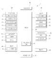
도 1은 본 발명의 일실시예에 따른 이동 단말기의 블록 구성도(block diagram)이다.1 is a block diagram of a mobile terminal according to an embodiment of the present invention.
이동 단말기(1)는 무선 통신부(10), A/V(Audio/Video) 입력부(20), 사용자 입력부(30), 센싱부(40), 출력부(50), 메모리(60), 인터페이스부(70), 제어부(80) 및 전원 공급부(90) 등을 포함할 수 있다.The
도 1에 도시된 구성요소들이 필수적인 것은 아니어서, 그보다 많은 구성요소들을 갖거나 그보다 적은 구성요소들을 갖는 이동 단말기가 구현될 수도 있다.The components shown in FIG. 1 are not essential, so that a mobile terminal having more or fewer components may be implemented.
이하, 상기 구성요소들에 대해 차례로 살펴본다.Hereinafter, the components will be described in order.
무선 통신부(10)는 이동 단말기(1)와 무선 통신 시스템 사이 또는 이동 단말기(1)와 이동 단말기(1)가 위치한 네트워크 사이의 무선 통신을 가능하게 하는 하나 이상의 모듈을 포함할 수 있는데, 예를 들어, 무선 통신부(10)는 방송 수신 모듈(11), 이동통신 모듈(12), 무선 인터넷 모듈(13), 근거리 통신 모듈(14) 및 위치정보 모듈(15) 등을 포함할 수 있다.The
또한, 방송 수신 모듈(11)은 방송 채널을 통하여 외부의 방송 관리 서버로부터 방송 신호 및/또는 방송 관련된 정보를 수신하고, 여기서, 방송 채널은 위성 채널, 지상파 채널을 포함할 수 있는데, 적어도 두 개의 방송 채널들에 대한 동시 방송 수신 또는 방송 채널 스위칭을 위해 둘 이상의 상기 방송 수신 모듈이 상기 이동단말기(1)에 제공될 수 있다.In addition, the
다음, 방송 관리 서버는, 방송 신호 및/또는 방송 관련 정보를 생성하여 송신하는 서버 또는 기 생성된 방송 신호 및/또는 방송 관련 정보를 제공받아 단말기에 송신하는 서버를 의미할 수 있으며, 여기서, 방송 신호는, TV 방송 신호, 라디오 방송 신호, 데이터 방송 신호를 포함할 뿐만 아니라, TV 방송 신호 또는 라디오 방송 신호에 데이터 방송 신호가 결합한 형태의 방송 신호도 포함할 수 있다.Next, the broadcast management server may mean a server that generates and transmits a broadcast signal and / or broadcast related information or a server that receives a pre-generated broadcast signal and / or broadcast related information and transmits the same to a terminal. The signal may include not only a TV broadcast signal, a radio broadcast signal, and a data broadcast signal, but also a broadcast signal in which a data broadcast signal is combined with a TV broadcast signal or a radio broadcast signal.
그리고, 방송 관련 정보는 방송 채널, 방송 프로그램 또는 방송 서비스 제공자에 관련한 정보를 의미할 수 있는데, 방송 관련 정보는, 이동 통신망을 통하여도 제공될 수 있으며, 이러한 경우에는 이동통신 모듈(12)에 의해 수신될 수 있다.The broadcast related information may mean information related to a broadcast channel, a broadcast program, or a broadcast service provider. The broadcast related information may also be provided through a mobile communication network. In this case, the broadcast related information may be provided by the
또한, 방송 관련 정보는 다양한 형태로 존재할 수 있는데, 예를 들어, DMB(Digital Multimedia Broadcasting)의 EPG(Electronic Program Guide) 또는 DVB-H(Digital Video Broadcast-Handheld)의 ESG(Electronic Service Guide) 등의 형태로 존재할 수 있다.In addition, broadcast-related information may exist in various forms, for example, an electronic program guide (EPG) of digital multimedia broadcasting (DMB) or an electronic service guide (ESG) of digital video broadcast-handheld (DVB-H). May exist in the form.
이어, 방송 수신 모듈(11)은, 예를 들어, DMB-T(Digital Multimedia Broadcasting-Terrestrial), DMB-S(Digital Multimedia Broadcasting-Satellite), MediaFLO(Media Forward Link Only), DVB-H(Digital Video Broadcast-Handheld), DVB-CBMS (Convergence of Broadcasting and Mobile Service), OMA-BCAST (Open Mobile Alliance-BroadCAST), CMMB (China Multimedia Mobile Broadcasting), MBBMS (Mobile Broadcasting Business Management System), ISDB-T(Integrated Services Digital Broadcast-Terrestrial) 등의 디지털 방송 시스템을 이용하여 디지털 방송 신호를 수신할 수 있다.Subsequently, the
물론, 방송 수신 모듈(11)은, 상술한 디지털 방송 시스템뿐만 아니라 다른 방송 시스템에 적합하도록 구성될 수도 있고, 방송 수신 모듈(11)을 통해 수신된 방송 신호 및/또는 방송 관련 정보는 메모리(60)에 저장될 수 있다.Of course, the
그리고, 이동통신 모듈(12)은, GSM(Gobal System for Mobile communications), CDMA(Code Division Multiple Access), WCDMA(Wideband CDMA)(이에 한정되지 않음)와 같은 이동 통신망 상에서 기지국, 외부의 단말, 서버 중 적어도 하나와 무선 신호를 송수신하는데, 여기서, 무선 신호는, 음성 호 신호, 화상 통화 호 신호 또는 문자/멀티미디어 메시지 송수신에 따른 다양한 형태의 데이터를 포함할 수 있다.The
이어, 무선 인터넷 모듈(13)은 무선 인터넷 접속을 위한 모듈을 말하는 것으로, 이동 단말기(1)에 내장되거나 외장될 수 있다.Subsequently, the
무선 인터넷 기술로는 WLAN(Wireless LAN)(Wi-Fi), Wibro(Wireless broadband), Wimax(World Interoperability for Microwave Access), HSDPA(High Speed Downlink Packet Access), GSM, CDMA, WCDMA, LTE(Long Term Evolution)(이에 한정되지 않음) 등이 이용될 수 있고, Wibro, HSDPA, GSM, CDMA, WCDMA, LTE 등에 의한 무선인터넷 접속은 이동통신망을 통해 이루어진다는 관점에서 본다면, 이동통신망을 통해 무선인터넷 접속을 수행하는 상기 무선 인터넷 모듈(13)은 상기 이동통신 모듈(12)의 일종으로 이해될 수도 있다.Wireless Internet technologies include Wireless LAN (Wi-Fi), Wireless Broadband (Wibro), World Interoperability for Microwave Access (Wimax), High Speed Downlink Packet Access (HSDPA), GSM, CDMA, WCDMA, Long Term Evolution) may be used, and wireless Internet access through Wibro, HSDPA, GSM, CDMA, WCDMA, LTE, etc. is made through a mobile communication network. The
다음, 근거리 통신 모듈(14)은 근거리 통신을 위한 모듈을 말하는데, 근거리 통신(short range communication) 기술로 블루투스(Bluetooth), RFID(Radio Frequency Identification), 적외선 통신(IrDA, infrared Data Association), UWB(Ultra Wideband), ZigBee 등이 이용될 수 있고, 위치정보 모듈(15)은 이동 단말기의 위치를 획득하기 위한 모듈로서, 그의 대표적인 예로는 GPS(Global Position System) 모듈이 있다.Next, the short
현재 기술에 의하면, GPS모듈(15)은 3개 이상의 위성으로부터 떨어진 거리 정보와 정확한 시간 정보를 산출한 다음, 산출된 정보에 삼각법을 적용함으로써, 위도, 경도, 및 고도에 따른 3차원의 현 위치 정보를 정확히 산출할 수 있는데, 현재, 3개의 위성을 이용하여 위치 및 시간 정보를 산출하고, 또 다른 1개의 위성을 이용하여 산출된 위치 및 시간 정보의 오차를 수정하는 방법이 널리 사용되고 있으며, 또한, GPS 모듈(15)은 현 위치를 실시간으로 계속 산출함으로써 속도 정보를 산출할 수도 있다.According to the current technology, the
도 1을 참조하면, A/V(Audio/Video) 입력부(20)는 오디오 신호 또는 비디오 신호 입력을 위한 것으로, 이에는 카메라(21)와 마이크(22) 등이 포함될 수 있다.Referring to FIG. 1, the A /
여기서, 카메라(21)는 화상 통화모드 또는 촬영 모드에서 이미지 센서에 의해 얻어지는 정지영상 또는 동영상 등의 화상 프레임을 처리하고, 처리된 화상 프레임은 디스플레이부(51)에 표시될 수 있으며, 카메라(21)에서 처리된 화상 프레임은 메모리(60)에 저장되거나 무선 통신부(10)를 통하여 외부로 전송될 수 있다.Here, the
경우에 따라, 카메라(21)는 사용 환경에 따라 2개 이상이 구비될 수도 있다.In some cases, two or
이어, 마이크(22)는 통화모드 또는 녹음모드, 음성인식 모드 등에서 마이크로폰(Microphone)에 의해 외부의 음향 신호를 입력받아 전기적인 음성 데이터로 처리하고, 처리된 음성 데이터는 통화 모드인 경우 이동통신 모듈(12)을 통하여 이동통신 기지국으로 송신 가능한 형태로 변환되어 출력될 수 있으며, 경우에 따라, 마이크(22)에는 외부의 음향 신호를 입력받는 과정에서 발생되는 잡음(noise)을 제거하기 위한 다양한 잡음 제거 알고리즘이 구현될 수 있다.Subsequently, the
다음, 사용자 입력부(30)는 사용자가 단말기의 동작 제어를 위한 입력 데이터를 발생시키는데, 사용자 입력부(30)는, 이동단말기(1)의 전·후면 또는 측면에 위치하는 버튼(36), 터치 센서(정압/정전)(37)로 구성될 수 있고, 도시되지는 않았지만 키패드(key pad), 돔 스위치 (dome switch), 조그 휠, 조그 스위치 등을 더욱 포함하여 구성될 수 있다.Next, the
또한, 센싱부(40)는 이동 단말기(1)의 개폐 상태, 이동 단말기(1)의 위치, 사용자 접촉 유무, 이동 단말기의 방위, 이동 단말기의 가속/감속 등과 같이 이동 단말기(1)의 현 상태를 감지하여 이동 단말기(1)의 동작을 제어하기 위한 센싱 신호를 발생시키는데, 예를 들어 이동 단말기(1)가 슬라이드 폰 형태인 경우 슬라이드 폰의 개폐 여부를 센싱할 수 있다.In addition, the
또한, 전원 공급부(90)의 전원 공급 여부, 인터페이스부(70)의 외부 기기 결합 여부 등을 센싱할 수도 있다.In addition, whether the
한편, 센싱부(40)는 근접 센서(41)를 포함할 수도 있다.Meanwhile, the
이어, 출력부(50)는 시각, 청각 또는 촉각 등과 관련된 출력을 발생시키기 위한 것으로, 이에는 디스플레이부(51), 음향 출력 모듈(52), 알람부(53), 및 햅틱 모듈(54) 등이 포함될 수 있다.Subsequently, the
다음, 디스플레이부(51)는 이동 단말기(1)에서 처리되는 정보를 표시하는데, 예를 들어, 이동 단말기가 통화 모드인 경우 통화와 관련된 UI(User Interface) 또는 GUI(Graphic User Interface)를 표시하고, 이동 단말기(1)가 화상 통화 모드 또는 촬영 모드인 경우에는 촬영 또는/및 수신된 영상 또는 UI, GUI를 표시한다.Next, the
디스플레이부(51)는 액정 디스플레이(liquid crystal display, LCD), 박막 트랜지스터 액정 디스플레이(thin film transistor-liquid crystal display, TFT LCD), 유기 발광 다이오드(organic light-emitting diode, OLED), 플렉시블 디스플레이(flexible display), 3차원 디스플레이(3D display) 중에서 적어도 하나를 포함할 수 있으며, 이들 중 일부 디스플레이는 그를 통해 외부를 볼 수 있도록 투명형 또는 광투과형으로 구성될 수 있다.The
이는 투명 디스플레이라 호칭될 수 있는데, 투명 디스플레이의 대표적인 예로는 TOLED(Transparant OLED) 등이 있고, 디스플레이부(51)의 후방 구조 또한 광 투과형 구조로 구성될 수 있는데, 이러한 구조에 의하여, 사용자는 단말기 바디의 디스플레이부(51)가 차지하는 영역을 통해 단말기 바디의 후방에 위치한 사물을 볼 수 있다.This may be referred to as a transparent display. A representative example of the transparent display is TOLED (Transparant OLED) and the like, and the rear structure of the
이동 단말기(1)의 구현 형태에 따라 디스플레이부(51)이 2개 이상 존재할 수 있는데, 예를 들어, 이동 단말기(1)에는 복수의 디스플레이부들이 하나의 면에 이격되거나 일체로 배치될 수 있고, 또한 서로 다른 면에 각각 배치될 수도 있다.According to the implementation of the
디스플레이부(51)와 터치센서(37)가 상호 레이어 구조를 이루거나 일체형으로 형성되는 경우(이하, '터치 스크린'이라 함)에, 디스플레이부(51)는 출력 장치 이외에 입력 장치로도 사용될 수 있다.When the
터치 센서는, 예를 들어, 터치 필름, 터치 시트, 터치 패드 등의 형태를 가지는 경우 디스플레이부(51)에 적층되어 레이어 구조를 형성할 수도 있고, 디스플레이부(51)의 구성에 포함시켜 일체형으로 이루어질 수 있다.For example, when the touch sensor has a form of a touch film, a touch sheet, or a touch pad, the touch sensor may be stacked on the
터치 센서는 디스플레이부(51)의 특정 부위에 가해진 압력 또는 디스플레이부(51)의 특정 부위에 발생하는 정전 용량 등의 변화를 전기적인 입력신호로 변환하도록 구성될 수 있다.The touch sensor may be configured to convert a change in pressure applied to a specific portion of the
여기서, 터치 센서는 터치 되는 위치 및 면적뿐만 아니라, 터치 시의 압력까지도 검출할 수 있도록 구성될 수 있는데, 터치 센서에 대한 터치 입력이 있는 경우, 그에 대응하는 신호(들)는 터치 제어기(미도시)로 보내지고, 터치 제어기는 그 신호(들)를 처리한 다음 대응하는 데이터를 제어부(80)로 전송함으로써, 제어부(80)는 디스플레이부(51)의 어느 영역이 터치 되었는지 여부 등을 알 수 있게 된다.Here, the touch sensor may be configured to detect not only the position and area of the touch but also the pressure at the touch. When there is a touch input to the touch sensor, the corresponding signal (s) may be a touch controller (not shown). ) And the touch controller processes the signal (s) and then transmits the corresponding data to the
그리고, 근접 센서(41)는 터치스크린에 의해 감싸지는 이동 단말기의 내부 영역 또는 터치 스크린의 근처에 배치될 수 있으며, 근접 센서는 소정의 검출면에 접근하는 물체, 혹은 근방에 존재하는 물체의 유무를 전자계의 힘 또는 적외선을 이용하여 기계적 접촉이 없이 검출하는 센서를 말하는데, 근접 센서는 접촉식 센서보다는 그 수명이 길며 그 활용도 또한 높다.In addition, the
근접 센서의 예로는 투과형 광전 센서, 직접 반사형 광전 센서, 미러 반사형 광전 센서, 고주파 발진형 근접 센서, 정전용량형 근접 센서, 자기형 근접 센서, 적외선 근접 센서 등이 있다.Examples of the proximity sensor include a transmission photoelectric sensor, a direct reflection photoelectric sensor, a mirror reflection photoelectric sensor, a high frequency oscillation proximity sensor, a capacitive proximity sensor, a magnetic proximity sensor, and an infrared proximity sensor.
터치스크린이 정전식인 경우에는 포인터의 근접에 따른 전계의 변화로 포인터의 근접을 검출하도록 구성되며, 이 경우, 터치 스크린(터치 센서)은 근접 센서로 분류될 수도 있다.When the touch screen is capacitive, the touch screen may be classified as a proximity sensor by detecting a proximity of the pointer due to a change in electric field according to the proximity of the pointer. In this case, the touch screen (touch sensor) may be classified as a proximity sensor.
다음, 음향 출력 모듈(52)은 호신호 수신, 통화모드 또는 녹음 모드, 음성인식 모드, 방송수신 모드 등에서 무선 통신부(10)로부터 수신되거나 메모리(60)에 저장된 오디오 데이터를 출력할 수 있고, 음향 출력 모듈(52)은 이동 단말기(1)에서 수행되는 기능(예를 들어, 호신호 수신음, 메시지 수신음 등)과 관련된 음향 신호를 출력하기도 하는데, 이러한 음향 출력 모듈(52)에는 리시버(Receiver), 스피커(speaker), 버저(Buzzer) 등이 포함될 수 있다.Next, the
또한, 알람부(53)는 이동 단말기(1)의 이벤트 발생을 알리기 위한 신호를 출력하며, 이동 단말기에서 발생 되는 이벤트의 예로는 호 신호 수신, 메시지 수신, 키 신호 입력, 터치 입력 등이 있으며, 알람부(53)는 비디오 신호나 오디오 신호 이외에 다른 형태, 예를 들어 진동으로 이벤트 발생을 알리기 위한 신호를 출력할 수도 있다.In addition, the
비디오 신호나 오디오 신호는 디스플레이부(51)나 음성 출력 모듈(52)을 통해서도 출력될 수 있으므로, 이 경우 디스플레이부(51) 및 음성출력모듈(52)은 알람부(53)의 일종으로 분류될 수도 있다.Since the video signal or the audio signal may be output through the
그리고, 햅틱 모듈(haptic module)(54)은 사용자가 느낄 수 있는 다양한 촉각 효과를 발생시키는데, 햅틱 모듈(54)이 발생시키는 촉각 효과의 대표적인 예로는 진동이 있으며, 햅택 모듈(54)이 발생하는 진동의 세기와 패턴 등은 제어가능하다.In addition, the
햅틱 모듈(54)은, 진동 외에도, 접촉 피부면에 대해 수직 운동하는 핀 배열, 분사구나 흡입구를 통한 공기의 분사력이나 흡입력, 피부 표면에 대한 스침, 전극(eletrode)의 접촉, 정전기력 등의 자극에 의한 효과와, 흡열이나 발열 가능한 소자를 이용한 냉온감 재현에 의한 효과 등 다양한 촉각 효과를 발생시킬 수 있다.In addition to the vibration, the
또한, 햅틱 모듈(54)은 직접적인 접촉을 통해 촉각 효과의 전달할 수 있을 뿐만 아니라, 사용자가 손가락이나 팔 등의 근 감각을 통해 촉각 효과를 느낄 수 있도록 구현할 수도 있으며, 햅틱 모듈(54)은 이동 단말기(1)의 구성 태양에 따라 2개 이상이 구비될 수도 있다.In addition, the
이어, 메모리부(60)는 제어부(80)의 처리 및 제어를 위한 프로그램이 저장될 수도 있고, 입/출력되는 데이터들(예를 들어, 전화번호부, 메시지, 오디오, 정지영상, 동영상 등)의 임시 저장을 위한 기능을 수행할 수도 있다.Subsequently, the memory unit 60 may store a program for processing and controlling the
메모리부(60)에는 데이터들 각각에 대한 사용 빈도(예를 들면, 각 전화번호, 각 메시지, 각 멀티미디어에 대한 사용빈도)가 저장될 수도 있고, 메모리부(60)에는 터치스크린 상의 터치 입력시 출력되는 다양한 패턴의 진동 및 음향에 관한 데이터를 저장할 수도 있다.The memory unit 60 may store a frequency of use of each data (for example, each phone number, each message, and a frequency of use of each multimedia), and the memory unit 60 may provide a touch input on a touch screen. Data about vibration and sound of various patterns that are output may be stored.
메모리(60)는 플래시 메모리 타입(flash memory type), 하드디스크 타입(hard disk type), 멀티미디어 카드 마이크로 타입(multimedia card micro type), 카드 타입의 메모리(예를 들어 SD 또는 XD 메모리 등), 램(Random Access Memory, RAM), SRAM(Static Random Access Memory), 롬(Read-Only Memory, ROM), EEPROM(Electrically Erasable Programmable Read-Only Memory), PROM(Programmable Read-Only Memory), 자기 메모리, 자기 디스크, 광디스크 중 적어도 하나의 타입의 저장매체를 포함할 수 있다.The memory 60 may be a flash memory type, a hard disk type, a multimedia card micro type, a card type memory (for example, SD or XD memory), RAM (Random Access Memory, RAM), Static Random Access Memory (SRAM), Read-Only Memory (ROM), Electrically Erasable Programmable Read-Only Memory (EEPROM), Programmable Read-Only Memory (PROM), Magnetic Memory, Magnetic It may include a storage medium of at least one type of disk, optical disk.
이동 단말기(1)는 인터넷(internet)상에서 메모리(60)의 저장 기능을 수행하는 웹 스토리지(web storage)와 관련되어 동작할 수도 있다.The
그리고, 인터페이스부(70)는 이동 단말기(1)에 연결되는 모든 외부기기와의 통로 역할을 한는데, 인터페이스부(70)는 외부 기기로부터 데이터를 전송받거나, 전원을 공급받아 이동 단말기(1) 내부의 각 구성 요소에 전달하거나, 이동 단말기(1) 내부의 데이터가 외부 기기로 전송되도록 한다.In addition, the
예를 들어, 유/무선 헤드셋 포트, 외부 충전기 포트, 유/무선 데이터 포트, 메모리 카드(memory card) 포트, 식별 모듈이 구비된 장치를 연결하는 포트, 오디오 I/O(Input/Output) 포트, 비디오 I/O(Input/Output) 포트, 이어폰 포트 등이 인터페이스부(70)에 포함될 수 있다.For example, wired / wireless headset ports, external charger ports, wired / wireless data ports, memory card ports, ports for connecting devices with identification modules, audio input / output (I / O) ports, The video input / output (I / O) port, the earphone port, and the like may be included in the
이어, 식별 모듈은 이동 단말기(1)의 사용 권한을 인증하기 위한 각종 정보를 저장한 칩으로서, 사용자 인증 모듈(User Identify Module, UIM), 가입자 인증 모듈(Subscriber Identify Module, SIM), 범용 사용자 인증 모듈(Universal Subscriber Identity Module, USIM) 등을 포함할 수 있고, 식별 모듈이 구비된 장치(이하 '식별 장치')는, 스마트 카드(smart card) 형식으로 제작될 수 있다.Subsequently, the identification module is a chip that stores various types of information for authenticating the use authority of the
따라서, 식별 장치는 포트를 통하여 단말기(1)와 연결될 수 있다.Thus, the identification device can be connected to the
인터페이스부는 이동단말기(1)가 외부 크래들(cradle)과 연결될 때, 크래들로부터의 전원이 이동단말기(1)에 공급되는 통로가 되거나, 사용자에 의해 상기 크래들에서 입력되는 각종 명령 신호가 상기 이동단말기로 전달되는 통로가 될 수 있고, 크래들로부터 입력되는 각종 명령 신호 또는 전원은 이동단말기가 크래들에 정확히 장착되었음을 인지하기 위한 신호로 동작될 수도 있다.When the
다음, 제어부(controller)(80)는 통상적으로 이동 단말기의 전반적인 동작을 제어하는데, 예를 들어 음성 통화, 데이터 통신, 화상 통화 등을 위한 관련된 제어 및 처리를 수행하는데, 제어부(80)는 멀티 미디어 재생을 위한 멀티미디어 모듈(81)을 구비할 수도 있으며, 멀티미디어 모듈(81)은 제어부(80) 내에 구현될 수도 있고, 제어부(80)와 별도로 구현될 수도 있고, 제어부(80)는 터치스크린 상에서 행해지는 필기 입력 또는 그림 그리기 입력을 각각 문자 및 이미지로 인식할 수 있는 패턴 인식 처리를 행할 수 있다.Next, the
이어, 전원 공급부(90)는 제어부(80)의 제어에 의해 외부의 전원, 내부의 전원을 인가받아 각 구성요소들의 동작에 필요한 전원을 공급하며, 전원공급부(90)는, 예를 들어 배터리, 연결포트, 전원공급제어부 및 충전모니터링부를 포함할 수 있다.Subsequently, the
다음, 배터리는 충전 가능하도록 이루어지는 내장형 배터리가 될 수 있으며, 충전 등을 위하여 단말기 바디에 착탈 가능하게 결합될 수 있고, 연결포트는 배터리의 충전을 위하여 전원을 공급하는 외부 충전기가 전기적으로 연결되는 인터페이스(70)의 일 예로서 구성될 수 있다.Next, the battery may be a built-in battery that can be charged, it can be detachably coupled to the terminal body for charging, the connection port is an interface that is electrically connected to an external charger for supplying power for charging the battery It can be configured as an example of 70.
여기에 설명되는 다양한 실시예는 예를 들어, 소프트웨어, 하드웨어 또는 이들의 조합된 것을 이용하여 컴퓨터 또는 이와 유사한 장치로 읽을 수 있는 기록매체 내에서 구현될 수 있는데, 하드웨어적인 구현에 의하면, 여기에 설명되는 실시예는 ASICs (application specific integrated circuits), DSPs (digital signal processors), DSPDs (digital signal processing devices), PLDs (programmable logic devices), FPGAs (field programmable gate arrays, 프로세서(processors), 제어기(controllers), 마이크로 컨트롤러(micro-controllers), 마이크로 프로세서(microprocessors), 기타 기능 수행을 위한 전기적인 유닛 중 적어도 하나를 이용하여 구현될 수 있다.The various embodiments described herein may be implemented in a recording medium readable by a computer or a similar device using, for example, software, hardware or a combination thereof. According to the hardware implementation, the descriptions are provided herein. Examples are application specific integrated circuits (ASICs), digital signal processors (DSPs), digital signal processing devices (DSPDs), programmable logic devices (PLDs), field programmable gate arrays (FPCs), controllers (controllers) It may be implemented using at least one of micro-controllers, microprocessors, and electrical units for performing other functions.
일부의 경우에 본 명세서에서 설명되는 실시예들이 제어부(80) 자체로 구현될 수 있고, 소프트웨어적인 구현에 의하면, 본 명세서에서 설명되는 절차 및 기능과 같은 실시예들은 별도의 소프트웨어 모듈들로 구현될 수 있으며, 소프트웨어 모듈들 각각은 본 명세서에서 설명되는 하나 이상의 기능 및 작동을 수행할 수 있고, 적절한 프로그램 언어로 쓰여진 소프트웨어 어플리케이션으로 소프트웨어 코드가 구현될 수 있으며, 소프트웨어 코드는 메모리(60)에 저장되고, 제어부(80)에 의해 실행될 수 있다.In some cases the embodiments described herein may be implemented by the
이와 같이, 구성되는 이동 단말기는, 디스플레이 패널과 배터리 사이에 공간을 갖는 U자형의 클립 형태로 외관을 제작함으로써, 신체나 물건 등의 다양한 부위에 간편하게 거치할 수 있다.In this way, the mobile terminal configured can be easily mounted on various parts such as a body or an object by making an appearance in the form of a U-shaped clip having a space between the display panel and the battery.
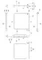
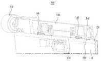
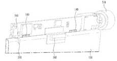
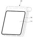
도 2는 본 발명의 일실시예에 따른 이동 단말기를 보여주는 도면으로서, 이동 단말기의 전면, 후면, 측면 및 상/하면을 보여주고 있다.2 is a view showing a mobile terminal according to an embodiment of the present invention, showing the front, rear, side and top / bottom of the mobile terminal.
도 2에 도시된 바와 같이, 이동 단말기는, 외관을 형성하는 케이스(case)(100), 케이스(100)의 전면부(100b)에 배치되는 디스플레이 패널(200), 그리고, 케이스(100)의 후면부(100c)에 배치되는 배터리(300)를 포함할 수 있다.As shown in FIG. 2, the mobile terminal includes a
그리고, 케이스(100)의 전면부(100b)와 후면부(100c)는, 케이스(100)의 연결부(100a)에 의해 연결될 수 있다.In addition, the
여기서, 케이스(100)의 연결부(100a)는, 케이스(100) 전면부(100b)의 일측과 케이스(100) 후면부(100c)의 일측을 연결할 수 있는데, 케이스(100) 전면부(100b)와 케이스(100) 후면부(100c)는, 일정 간격으로 공간(150)을 두고 배치될 수 있다.Here, the
그리고, 케이스(100)의 연결부(100a), 케이스(100) 전면부(100b) 및 케이스(100) 후면부(100c)는, 하나의 바디(body)로 이루어질 수 있다.In addition, the
하지만, 경우에 따라, 케이스(100)의 연결부(100a), 케이스(100) 전면부(100b) 및 케이스(100) 후면부(100c)는, 서로 분리되거나 또는 서로 체결될 수도 있다.However, in some cases, the
이어, 케이스(100) 전면부(100b)의 일측과 케이스(100) 후면부(100c)의 일측은, 케이스(100)의 연결부(100a)에 의해, 닫혀 있고, 케이스(100) 전면부(100b)의 타측과 케이스(100) 후면부(100c)의 타측은, 외부에 개방될 수 있다.Subsequently, one side of the
그리고, 케이스(100) 전면부(100b)의 일측과 케이스(100) 후면부(100c)의 일측 사이의 제 2 간격 d2과, 케이스(100) 전면부(100b)의 타측과 케이스(100) 후면부(100c)의 타측 사이의 제 1 간격 d1은, 서로 동일할 수 있다.Then, the second interval d2 between one side of the
하지만, 경우에 따라서, 제 1 간격 d1과 제 2 간격 d2은 서로 다를 수도 있다.However, in some cases, the first interval d1 and the second interval d2 may be different from each other.
일 예로, 제 1 간격 d1과 제 2 간격 d2은, 약 0.5 - 30mm일 수 있다.For example, the first interval d1 and the second interval d2 may be about 0.5-30 mm.
또한, 케이스(100)의 연결부(100a)에는, 디스플레이 패널(200)을 구동시키는 회로 모듈을 더 포함할 수 있다.In addition, the
일 예로, 회로 모듈은, 일측에 이어잭(510)이 배치되고, 타측에 전원키가 배치될 수 있다.For example, in the circuit module, an
도 3a는 도 2의 A-A 선상에 따른 단면도이고, 도 3b는 도 2의 B-B 선상에 따른 단면도이다.3A is a cross-sectional view taken along the line A-A of FIG. 2, and FIG. 3B is a cross-sectional view taken along the line B-B of FIG.
도 3a 및 도 3b에 도시된 바와 같이, 케이스(100)의 연결부(100a)에는, 디스플레이 패널을 구동시키는 회로 모듈(500)이 배치될 수 있다.As shown in FIGS. 3A and 3B, a
일 예로, 회로 모듈(500)은, 일측에 이어잭(510)이 배치되고, 타측에 전원키가 배치될 수 있다.For example, in the
그리고, 케이스(100)의 연결부(100a)는, 케이스(100) 전면부(100b)의 일측과 케이스(100) 후면부(100c)의 일측을 연결할 수 있는데, 케이스(100) 전면부(100b)와 케이스(100) 후면부(100c)는, 일정 간격으로 공간(150)을 두고 배치될 수 있다.In addition, the
즉, 케이스(100) 전면부(100b)의 일측과 케이스(100) 후면부(100c)의 일측은, 케이스(100)의 연결부(100a)에 의해, 닫혀 있고, 케이스(100) 전면부(100b)의 타측과 케이스(100) 후면부(100c)의 타측은, 외부에 개방될 수 있다.That is, one side of the
그리고, 케이스(100) 전면부(100b)의 일측과 케이스(100) 후면부(100c)의 일측 사이의 제 2 간격 d2과, 케이스(100) 전면부(100b)의 타측과 케이스(100) 후면부(100c)의 타측 사이의 제 1 간격 d1은, 서로 동일할 수 있다.Then, the second interval d2 between one side of the
일 예로, 제 1 간격 d1과 제 2 간격 d2은, 약 0.5 - 30mm일 수 있다.For example, the first interval d1 and the second interval d2 may be about 0.5-30 mm.
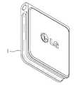
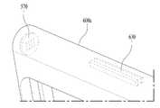
도 4a 및 도 4b는 본 발명의 일실시예에 따른 이동 단말기의 외관을 보여주는 사시도로서, 도 4a는 전면 사시도이고, 도 4b는 후면 사시도이다.4A and 4B are perspective views showing the appearance of a mobile terminal according to an embodiment of the present invention. FIG. 4A is a front perspective view and FIG. 4B is a rear perspective view.
도 4a 및 도 4b에 도시된 바와 같이, 이동 단말기(1)는, 전면부에 디스플레이 패널이 배치되고, 후면부에 배터리가 배치될 수 있다.As shown in FIGS. 4A and 4B, the
그리고, 이동 단말기(1)는, 디스플레이 패널에, 음악, 사진 및 동영상 등을 재생할 뿐만 아니라, 시간, 날씨 등과 같은 다양한 정보를 표시할 수 있다.The
또한, 이동 단말기(1)는, 디스플레이 패널이 배치되는 전면부와 배터리가 배치되는 후면부가 일정 간격으로 공간을 두고 배치되어, 클립 형상을 가질 수 있다.In addition, the
도 5a 및 도 5b는 바지 주머니에 거치되는 클립형 이동 단말기를 보여주는 도면으로서, 도 5a는 이동 단말기의 이어잭에 이어폰이 연결되어 음악이 재생되는 도면이고, 도 5b는 이어폰의 연결 없이, 이동 단말기에 시간, 날씨 등과 같은 다양한 정보가 표시되는 도면이다.Figures 5a and 5b is a view showing a clip-type mobile terminal is mounted on the pants pocket, Figure 5a is a view that the earphone is connected to the ear jack of the mobile terminal to play music, Figure 5b is a mobile terminal without the connection of the earphone Various information such as time and weather are displayed.
도 5a 및 도 5b에 도시된 바와 같이, 본 발명의 이동 단말기는, U자형 클립 형상으로 제작되어, 신체의 다양한 부위에 거치하여 편리하게 휴대할 수 있다.5A and 5B, the mobile terminal of the present invention is manufactured in a U-shaped clip shape, and can be conveniently mounted on various parts of the body.
일 예로, 이동 단말기를 사용자의 바지 주머니에 거치하는 경우, 이동 단말기의 후면부는 바지 주머니 안쪽을 향하고, 이동 단말기의 전면부는 바지 주머니의 바깥쪽을 향하도록 배치될 수 있다.For example, when the mobile terminal is mounted in the pants pocket of the user, the rear portion of the mobile terminal may face the inside of the pants pocket, and the front portion of the mobile terminal may be disposed toward the outside of the pants pocket.
이동 단말기의 전면부와 후면부 사이의 공간에 소정의 센서가 배치되어, 이동 단말기의 전면부와 후면부 사이의 공간 내에 바지 주머니가 삽입되면, 이동 단말기의 센서는, 이동 단말기의 거치를 인식하고, 이동 단말기를 자동으로 구동시킬 수도 있다.When a predetermined sensor is disposed in the space between the front and rear portions of the mobile terminal, and the pants pocket is inserted into the space between the front and rear portions of the mobile terminal, the sensor of the mobile terminal recognizes the mounting of the mobile terminal and moves You can also run the terminal automatically.
즉, 사용자가 별도로 이동 단말기를 작동시키지 않아도, 이동 단말기는, 센서의 센싱 신호에 따라, 이동 단말기의 거치가 확인되면, 미리 설정된 다양한 유저 인터페이스를 실행하거나, 또는 초기 동작을 실행할 수 있지만, 이에 제한되지는 않는다.That is, even if the user does not operate the mobile terminal separately, the mobile terminal may execute various preset user interfaces or execute an initial operation when the mounting of the mobile terminal is confirmed according to the sensing signal of the sensor. It doesn't work.
도 6은 도 2의 케이스 연결부에 배치되는 회로 모듈을 보여주는 사시도이다.6 is a perspective view illustrating a circuit module disposed in the case connection unit of FIG. 2.
도 6에 도시된 바와 같이, 회로 모듈(500)은, 기판(520), 제 1 커넥터(도시되지 않음), 제 2 커넥터(530), 이어잭(510), 전원키(540)를 포함할 수 있다.As shown in FIG. 6, the
여기서, 기판(520)은, 케이스 연결부 내에 배치되는 연결 프레임의 외면에 대해, 수직한 방향으로 장착될 수 있다.Here, the
그리고, 제 1 커넥터(도시되지 않음)는, 기판(520)의 전면에 배치되어, 디스플레이 패널에 전기적으로 연결될 수 있다.The first connector (not shown) may be disposed on the front surface of the
이어, 제 2 커넥터(530)는, 기판(520)의 후면에 배치되어, 배터리에 전기적으로 연결될 수 있다.Subsequently, the
또한, 기판(520)의 일측에는, 외부의 이어폰과의 연결을 위한 이어잭(510)이 배치될 수 있고, 기판(520)의 타측에는, 전원키(540)를 배치할 수 있다.In addition, an
추가적으로, 회로 모듈(500)에는, 연결 프레임에 연결되어, 프레임의 변형을 센싱하는 핑거 클립(finger clip)(550)이 더 포함될 수도 있다.In addition, the
이 외에도, 회로 모듈(500)에는, 마이크 및 근접 센서 등 다양한 부가 요소들이 더 포함될 수 있다.In addition, the
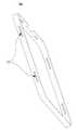
도 7은 도 2의 케이스 내에 배치되는 프레임을 보여주는 사시도이다.7 is a perspective view illustrating a frame disposed in the case of FIG. 2.
도 7에 도시된 바와 같이, 케이스 내의 프레임(105)은, 디스플레이 패널을 지지하는 제 1 프레임(130), 배터리를 지지하는 제 2 프레임(110), 그리고, 제 1 프레임(130)의 일측과 제 2 프레임(110)의 일측을 연결하는 연결 프레임(120)을 포함할 수 있다.As shown in FIG. 7, the
여기서, 제 1 프레임(130)과 제 2 프레임(110)은 일정 간격 d으로 공간을 두고 배치될 수 있다.Here, the
그리고, 제 1, 제 2 프레임(130, 110) 및 연결 프레임(120)은, 하나의 바디(body)로 이루어질 수 있다.In addition, the first and
하지만, 경우에 따라, 제 1, 제 2 프레임(30, 110) 및 연결 프레임(120)은, 서로 분리되거나 또는 서로 체결될 수도 있다.However, in some cases, the first and
또한, 제 1 프레임(130)과 제 2 프레임(110) 사이의 간격 d은, 약 0.5 - 30mm일 수 있다.In addition, an interval d between the
이어, 제 1 프레임(130)의 일측과 제 2 프레임(110)의 일측은, 연결 프레임(120)에 의해, 닫혀 있고, 제 1 프레임(130)의 타측과 제 2 프레임(110)의 타측은, 외부에 개방될 수 있다.Subsequently, one side of the
여기서, 제 1 프레임(130)의 일측과 제 2 프레임(110)의 일측 사이의 제 1 간격과, 제 1 프레임(130)의 타측과 제 2 프레임(110)의 타측 사이의 제 2 간격은, 서로 동일할 수 있다.Here, the first interval between one side of the
하지만, 경우에 따라서, 제 1 프레임(130)의 일측과 제 2 프레임(110)의 일측 사이의 제 1 간격과, 제 1 프레임(130)의 타측과 제 2 프레임(110)의 타측 사이의 제 2 간격은, 서로 다를 수도 있다.However, in some cases, the first gap between one side of the
다음, 연결 프레임(120)의 외면에는, 적어도 하나의 고정 클립(140)이 배치될 수 있는데, 고정 클립(140)에 의해, 연결 프레임(120)과 회로 모듈은 서로 체결될 수 있다.Next, at least one
즉, 회로 모듈의 기판은, 연결 프레임(120)의 외면으로부터 돌출되는 적어도 하나의 고정 클립(140)에 체결될 수 있다.That is, the substrate of the circuit module may be fastened to at least one
그리고, 제 1, 제 2 프레임(130, 110) 중, 어느 하나에는, 패드(410)가 배치될 수 있다.The
여기서, 패드(410)는, 센서의 충격 방지를 위한 완충재로서, 센서에 대응하여 배치될 수 있다.Here, the
즉, 패드(410)는, 센서와 프레임(105) 사이에 배치될 수 있는데, 패드(140)에는, 센서의 노출을 위한 홀(420)이 형성될 수 있다.That is, the
이때, 프레임(105)은, 패드(410)의 홀(420)이 대응되는 영역에 동일한 크기의 관통홀이 배치될 수 있다.In this case, the through hole of the same size may be disposed in the region of the
예를 들면, 제 1, 제 2 프레임(130, 110) 중, 적어도 어느 하나의 일측에는, 적어도 하나의 관통홀이 형성될 수 있다.For example, at least one through hole may be formed on at least one side of the first and
그리고, 관통홀이 형성된 영역에는, 적어도 하나의 센서가 배치될 수 있는데, 센서는 관통홀을 통해, 노출되고, 제 1 프레임(130)과 제 2 프레임(110) 사이의 공간을 센싱하여, 케이스의 거치 유무를 인식할 수 있다.In addition, at least one sensor may be disposed in a region where the through hole is formed, and the sensor is exposed through the through hole and senses a space between the
따라서, 센서는, 패드(410)의 홀(420)과, 프레임(105)의 관통홀을 통해, 제 1 프레임(130)과 제 2 프레임(110) 사이의 공간에 노출될 수 있다.Therefore, the sensor may be exposed to the space between the
또한, 제 1 프레임(130)의 바디 영역(130a)과, 제 2 프레임(110)의 바디 영역(110a)은, 제 1 재질로 이루어지고, 제 1 프레임(130)의 가장자리 영역(130b)과, 제 2 프레임(110)의 가장자리 영역(110b)은, 제 2 재질로 이루어질 수 있다.In addition, the
여기서, 제 1 재질과 제 2 재질은 서로 다를 수 있다.Here, the first material and the second material may be different from each other.
일 예로, 제 1 재질은, 금속 재질일 수 있고, 제 2 재질은, 수지 재질일 수 있다.For example, the first material may be a metal material, and the second material may be a resin material.
제 1 프레임(130)의 가장자리 영역(130b)과, 제 2 프레임(110)의 가장자리 영역(110b)을, 금속 재질이 아닌 수지 재질로 하면, 이동 단말기의 거치시, 프레임(105)의 끝단과 거치 영역 사이의 마찰로 인하여, 거치 영역에 손상이 가하는 것을 방지할 수 있다.When the
따라서, 제 1 프레임(130)의 가장자리 영역(130b)과, 제 2 프레임(110)의 가장자리 영역(110b)은, 몰드(mold)로 구현될 수 있다.Therefore, the
그리고, 제 1 프레임(130)의 바디 영역(130a)과, 제 2 프레임(110)의 바디 영역(110a)은, 금속 재질로 형성함으로서, 외부 충격으로부터 이동 단말기의 변형을 방지할 수 있다.The
그리고, 제 1 프레임(130)의 가장자리 영역(130b)과, 제 2 프레임(110)의 가장자리 영역(110b)에는, 적어도 하나의 체결 홀(132)이 형성될 수 있다.At least one
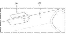
도 8 및 도 9는 도 7의 고정 클립을 보여주는 도면이다.8 and 9 are views showing the fixing clip of FIG.
도 8 및 도 9에 도시된 바와 같이, 프레임(105)은, 디스플레이 패널을 지지하는 제 1 프레임(130), 배터리를 지지하는 제 2 프레임(110), 그리고, 제 1 프레임(130)의 일측과 제 2 프레임(110)의 일측을 연결하는 연결 프레임(120)을 포함할 수 있는데, 연결 프레임(120)의 외면에는, 적어도 하나의 고정 클립(140)이 배치될 수 있다.As shown in FIGS. 8 and 9, the
여기서, 고정 클립(140)은, 회로 모듈의 기판을 고정함으로써, 연결 프레임(120)과 회로 모듈을 서로 체결할 수 있다.Here, the fixing
일 예로, 고정 클립(140)은, 다양한 형상으로 제작될 수 있는데, 본 발명에서는 U자형의 클립 형상을 가질 수 있다.For example, the fixing
여기서, 고정 클립(140)은, 연결 프레임(120)에 인접하는 영역의 공간 면적이 연결 프레임(120)으로부터 먼 영역의 공간 면적보다 더 넓은 형상을 가질 수 있다.Here, the fixing
그리고, 제 1, 제 2 프레임(130, 110) 중, 어느 하나에는, 패드(410)가 배치될 수 있는데, 패드(410)는, 센서의 충격 방지를 위한 완충재로서, 센서에 대응하여 배치될 수 있다.The
즉, 패드(410)는, 센서와 프레임(105) 사이에 배치될 수 있는데, 패드(140)에는, 센서의 노출을 위한 홀(420)이 형성될 수 있다.That is, the
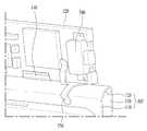
도 10a 및 도 10b는 회로 모듈과 프레임의 체결을 보여주는 도면으로서, 도 10a는 체결 후면도이고, 도 10b는 체결 전면도이다.10A and 10B are views showing the fastening of the circuit module and the frame. FIG. 10A is a fastening rear view and FIG. 10B is a fastening front view.
도 10a 및 도 10b에 도시된 바와 같이, 회로 모듈(500)은, 연결 프레임(120)의 외면에 대해, 수직한 방향으로 장착될 수 있다.10A and 10B, the
여기서, 회로 모듈(500)의 기판(520)은, 연결 프레임(120)의 외면에 배치되는 고정 클립(140)에 체결될 수 있다.Here, the
즉, 고정 클립(140)은, 회로 모듈(500)의 기판(520)을 안정적으로 고정시키기 위하여, 다수 개가 배치될 수 있다.That is, a plurality of fixing
고정 클립(140)에 장착된 회로 모듈(500)은, 기판(520)의 일측에, 외부의 이어폰과의 연결을 위한 이어잭(510)이 배치될 수 있고, 기판(520)의 타측에, 전원키(540)가 배치될 수 있다.In the
그리고, 회로 모듈(500)의 제 1 커넥터(560)는, 제 1 프레임(130) 상에 배치되어, 디스플레이 패널과의 전기적 연결이 쉽고, 회로 모듈(500)의 제 2 커넥터(530)는, 제 2 프레임(110) 상에 배치되어, 배터리와의 전기적 연결이 쉬울 수 있다.In addition, the
그리고, 핑거 클립(550)의 상부는, 회로 모듈(500)의 기판(520)을 연결하고, 핑거 클립의 하부는, 연결 프레임(120)에 연결되어, 프레임의 변형을 센싱할 수 있다.In addition, an upper portion of the
여기서, 핑거 클립(550)은, 제 1 프레임(130)과 회로 모듈(500)의 뒷면에 접촉되는 제 1 클립과, 제 1 클립에 연결되고 제 2 프레임(110)과 회로 모듈(500)의 앞면에 접촉되는 제 2 클립과, 제 1 클립에 돌출 배치되어, 제 1 프레임(130)과 제 1 클립을 전기적으로 연결하는 제 1 돌기와, 제 2 클립에 돌출 배치되어, 제 2 프레임(110)과 제 2 클립을 전기적으로 연결하는 제 2 돌기를 포함할 수 있다.Here, the
경우에 따라, 핑거 클립은, 제 1, 제 2 돌기 대신에, 제 1 클립에 배치되어, 제 1 프레임(130)과 제 1 클립의 접촉 유무를 센싱하는 제 1 센서와, 제 2 클립에 배치되어, 제 2 프레임(110)과 제 2 클립의 접촉 유무를 센싱하는 제 2 센서를 포함할 수도 있다.In some cases, the finger clip is disposed on the first clip, instead of the first and second protrusions, and is disposed on the first sensor and the second clip that sense the contact between the
이처럼, 이동 단말기는, 프레임 변형에 따른, 핑거 클립(550)과의 전기적 연결 유무에 따라, 다양한 유저 인터페이스를 실행함으로써, 사용자에게 다양한 이벤트를 제공할 수 있다.As such, the mobile terminal may provide various events to the user by executing various user interfaces according to whether or not the electrical connection with the
따라서, 사용자는, 소정의 기능을 실행시키기 위하여, 이동 단말기를 복잡하게 조작하지 않고, 이동 단말기의 프레임을 약간의 힘으로 변형시킴으로써, 간단하게 원하는 기능을 실행시킬 수 있다.Therefore, the user can simply execute the desired function by deforming the frame of the mobile terminal with a slight force without complicated operation of the mobile terminal in order to execute the predetermined function.
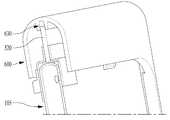
도 11 및 도 12는 도 2의 케이스를 구성하는 프레임 커버를 보여주는 도면으로서, 도 11은 프레임 커버의 전면, 후면, 측면 및 상/하면을 보여주고, 도 12는 프레임 커버의 사시도이다.11 and 12 are views illustrating a frame cover constituting the case of FIG. 2, FIG. 11 is a front, rear, side, and top and bottom surfaces of the frame cover, and FIG. 12 is a perspective view of the frame cover.
도 11 및 도 12에 도시된 바와 같이, 프레임 커버(600)는, 제 1, 제 2 프레임 및 연결 프레임의 가장자리 영역과 회로 모듈을 커버할 수 있다.As illustrated in FIGS. 11 and 12, the
여기서, 프레임 커버(600)는, 디스플레이 패널을 노출시키는 제 1 개구부(610)와, 배터리를 노출시키는 제 2 개구부(620)를 포함할 수 있다.The
그리고, 프레임 커버(600)는, 회로 모듈을 마주하는 내측면으로부터 돌출되어, 회로 모듈을 고정하는 고정 리브(630)가 배치될 수 있다.In addition, the
또한, 프레임 커버(600)는, 제 1 프레임의 가장자리 영역을 커버하는 제 1 커버(600b), 제 2 프레임의 가장자리 영역을 커버하는 제 2 커버(600c), 그리고, 연결 프레임을 커버하는 연결 커버(600a)를 포함할 수 있다.In addition, the
여기서, 연결 커버(600a)는, 제 1 커버(600b)의 일측과, 제 2 커버(600c)의 일측을 연결할 수 있다.Here, the
그리고, 연결 커버(600a)는, 연결 프레임에 장착되는 회로 모듈을 커버함으로써, 회로 모듈을 외부로부터 보호할 수 있다.And the
또한, 연결 커버(600a)는, 내측면에 고정 리브(630)가 돌출되어 배치될 수 있는데, 고정 리브(630)는, 회로 모듈의 기판과 체결되어, 회로 모듈을 안정적으로 고정시킬 수 있다.In addition, the
여기서, 고정 리브(630)는, 연결 커버(600a)의 길이 방향으로 2개가 배치되고, 2개 고정 리브(630)들 사이에 회로 모듈의 기판이 삽입될 수 있다.Here, two fixed
그리고, 연결 커버(600a)의 일측에는 체결 홀(660)이 형성될 수 있는데, 연결 커버(600a)의 체결 홀(660)에는, 전원 키를 커버하는 전원 버튼(570)이 삽입될 수 있다.In addition, a
이어, 제 1, 제 2 개구부(610, 620)의 주변에는, 내측 방향으로 돌출되는 다수의 후크(hook)(640)와 다수의 보스(boss)(650)가 배치될 수 있다.Subsequently, a plurality of
여기서, 제 1 개구부(610)의 주변에 배치되는 후크(640)는, 디스플레이 패널의 주변을 커버하는 패널 커버에 체결될 수 있고, 제 2 개구부(620)의 주변에 배치되는 후크(640)는, 배터리 전면을 커버하는 배터리 커버에 체결될 수 있다.Here, the
이와 같이, 프레임 커버(600)는 몰드로 구현될 수 있는데, 일 예로 수지 재질일 수 있다.As such, the
따라서, 프레임 커버(600)는, U자 형상의 클립형으로 구현되어, 소정의 힘이 가해지면, 휘어질 수 있는 경도(hardness)를 가질 수 있다.Accordingly, the
도 13은 도 12의 후크와 보스의 배치를 보여주는 사시도이다.FIG. 13 is a perspective view illustrating an arrangement of a hook and a boss of FIG. 12.
도 13에 도시된 바와 같이, 프레임 커버(600)는, 제 1 개구부를 갖는 제 1 커버(600b), 제 2 개구부를 갖는 제 2 커버(600c), 그리고, 제 1 커버(600b)와 제 2 커버(600c)를 연결하는 연결 커버(600a)를 포함할 수 있다.As shown in FIG. 13, the
여기서, 제 1, 제 2 개구부의 주변에는, 내측 방향으로 돌출되는 다수의 후크(640)와 다수의 보스(650)가 배치될 수 있다.Here, a plurality of
이때, 후크(640)는, 제 1 커버(600b)에 배치되는 제 1 후크(640a)와 제 2 커버(600c)에 배치되는 제 2 후크(640b)를 포함할 수 있는데, 제 1 커버(600b)에 배치되는 제 1 후크(640a)와 제 2 커버(600c)에 배치되는 제 2 후크(640b)는 서로 대응하여 마주보도록 배치될 수 있다.In this case, the
그리고, 보스(650)는, 제 1 커버(600b)에 배치되는 제 1 보스(650a)와 제 2 커버(600c)에 배치되는 제 2 보스(650b)를 포함할 수 있는데, 제 1 커버(600b)에 배치되는 제 1 보스(650a)와 제 2 커버(600c)에 배치되는 제 2 보스(650b)는 서로 대응하여 마주보도록 배치될 수 있다.The
도 14는 도 12의 고정 리브를 보여주는 도면이다.14 is a view showing the fixing rib of FIG.
도 14에 도시된 바와 같이, 프레임 커버의 연결 커버(600a)는, 회로 모듈을 마주하는 내측면으로부터 돌출되어, 회로 모듈을 고정하는 고정 리브(630)가 배치될 수 있다.As shown in FIG. 14, the
여기서, 고정 리브(630)는, 회로 모듈의 기판과 체결되어, 회로 모듈을 안정적으로 고정시킬 수 있다.Here, the fixed
따라서, 고정 리브(630)는, 연결 커버(600a)의 길이 방향으로 2개가 배치될 수 잇는데, 2개 고정 리브(630)들 사이로 회로 모듈의 기판이 삽입됨으로써, 체결될 수 있다.Accordingly, two fixed
그리고, 연결 커버(600a)의 일측에는 체결 홀이 형성될 수 있는데, 연결 커버(600a)의 체결 홀에는, 전원 키를 커버하는 전원 버튼(570)이 삽입될 수 있다.In addition, a fastening hole may be formed at one side of the
도 15 내지 도 17은 회로 모듈이 장착된 프레임과 프레임 커버의 체결을 보여주는 도면으로서, 도 15는 체결 방향을 보여주는 도면이고, 도 16은 체결 부위를 보여주는 도면이며, 도 17은 체결이 완료된 도면이다.15 to 17 are views showing the fastening of the frame and the frame cover on which the circuit module is mounted, FIG. 15 is a view showing a fastening direction, FIG. 16 is a view showing a fastening portion, and FIG. 17 is a fastening completed. .
도 15 내지 도 17에 도시된 바와 같이, 프레임 커버(600)는, 회로 모듈(500)이 장착된 프레임(105)에 체결하기 위해서, 회로 모듈(500)이 배치된 방향으로 이동하는데, 회로 모듈(500)부터 프레임 커버(600) 내에 삽입되고, 이어 프레임(105)이 프레임 커버(600) 내로 삽입될 수 있다.As shown in FIGS. 15 to 17, the
여기서, 회로 모듈(500)의 기판(520)은, 프레임 커버(600)의 고정 리브(630) 내로 삽입되어 체결될 수 있다.Here, the
따라서, 프레임(105)은 프레임 커버(600)의 개구부에 노출되고, 회로 모듈(500)은 프레임 커버(600) 내로 삽입될 수 있다.Accordingly, the
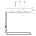
도 18은 디스플레이 패널의 체결을 보여주는 도면이다.18 is a view illustrating fastening of a display panel.
도 18에 도시된 바와 같이, 프레임 커버(600)는, 프레임(105)에 체결되는데, 프레임(105)은 프레임 커버(600)의 개구부에 노출될 수 있다.As shown in FIG. 18, the
여기서, 노출된 프레임 커버(600)의 개구부 내에 디스플레이 패널(200)이 장착되고, 디스플레이 패널(200)은, 회로 모듈의 제 1 커넥터(560)에 전기적으로 연결될 수 있다.Here, the
일 예로, 디스플레이 패널(200)은, 집 커넥터(Zip Connector) 또는 비투비 커넥터(B-to-B Connector)로 체결될 수 있지만, 이에 한정되지는 않는다.For example, the
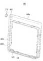
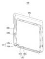
도 19는 패널 커버를 보여주는 도면이고, 도 20a 및 도 20b는 패널 커버의 체결을 보여주는 도면이다.19 is a view showing a panel cover, Figure 20a and 20b is a view showing the fastening of the panel cover.
도 19에 도시된 바와 같이, 패널 커버(700)는, 프레임 커버의 다수의 후크에 체결되어, 디스플레이 패널의 주변을 커버할 수 있다.As shown in FIG. 19, the
여기서, 패널 커버(700)는 측면에 다수의 체결 홀(710)들이 배치될 수 있는데, 다수의 체결 홀(710)들은, 프레임 커버의 후크들에 각각 대응하여 배치될 수 있다.Here, the
따라서, 패널 커버(700)의 체결 홀(710)의 개수는, 프레임 커버의 후크의 개수와 동일할 수 있다.Therefore, the number of
그리고, 패널 커버(700)는, 전면 및 후면이 오픈되는 개구부를 가짐으로써, 디스플레이 패널을 외부로 노출시킬 수 있다.In addition, the
여기서, 패널 커버(700)는 몰드로 구현될 수 있는데, 일 예로 수지 재질일 수 있다.Here, the
도 20a에 도시된 바와 같이, 패널 커버(700)는, 디스플레이 패널(200)의 주변부를 커버할 수 있다.As shown in FIG. 20A, the
여기서, 패널 커버(700)는, 디스플레이 패널(200)의 주변을 감싸도록 배치되어, 프레임 커버(600)의 노출 영역을 모두 커버할 수 있으므로, 외부의 이물질이 이동 단말기 내부로 침투되는 것을 막아줄 수 있다.Here, the
이어, 도 20b에 도시된 바와 같이, 디스플레이 패널의 전면에는, 보호창(window)(210)이 테이프 또는 본딩되어 조립될 수 있다.Subsequently, as shown in FIG. 20B, a
여기서, 보호창(210)은, 외부의 충격으로부터, 디스플레이 패널을 보호할 수 있다.Here, the
도 21은 배터리를 보여주는 도면이고, 도 22a 및 도 22b는 배터리의 체결을 보여주는 도면이다.21 is a view showing a battery, Figure 22a and 22b is a view showing the fastening of the battery.
도 21에 도시된 바와 같이, 배터리(300)는, 일측에 회로 모듈과 전기적으로 연결하기 위한 배터리 커넥터(310)가 배치될 수 있다.As shown in FIG. 21, the
여기서, 배터리 커넥터(310)는, 회로 모듈의 제 2 커넥터와 대응되는 위치에 배치될 수 있는데, 일측에서 외부로 돌출될 수 있다.Here, the
그리고, 도 22a에 도시된 바와 같이, 프레임 커버(600)는, 프레임(105)에 체결되는데, 프레임(105)은 프레임 커버(600)의 개구부에 노출될 수 있다.And, as shown in Figure 22a, the
여기서, 노출된 프레임 커버(600)의 개구부 내에 배터리(300)이 장착되고, 배터리(300)은, 배터리 커넥터(310)가 회로 모듈의 제 2 커넥터에 전기적으로 연결될 수 있다.Here, the
일 예로, 배터리(300)은, 커넥터 타입으로 체결될 수 있지만, 이에 한정되지는 않는다.For example, the
이어, 도 22b에 도시된 바와 같이, 배터리 상부에 배터리 보호를 위한 배터리 커버(320)가 장착될 수 있다.Subsequently, as illustrated in FIG. 22B, a
여기서, 배터리 커버(320)는, 프레임 커버의 후크에 체결되어, 배터리 전면을 커버할 수 있다.Here, the
또한, 배터리 커버(320)는 몰드로 구현될 수 있는데, 일 예로 수지 재질일 수 있다.In addition, the
따라서, 경우에 따라, 배터리 커버(320), 패널 커버와 프레임 커버는, 서로 동일한 재질일 수 있다.Therefore, in some cases, the
다른 경우로서, 배터리 커버(320), 패널 커버와 프레임 커버는, 서로 다른 재질일 수도 있다.In another case, the
또 다른 경우로서, 배터리 커버(320), 패널 커버와 프레임 커버는, 제 1, 제 2 프레임 및 연결 프레임과 다른 재질일 수 있다.In another case, the
도 23a 및 도 23b는 센서의 위치를 보여주는 도면이다.23A and 23B show the position of the sensor.
도 23a 및 도 23b에 도시된 바와 같이, 케이스 내의 프레임은, 디스플레이 패널(200)을 지지하는 제 1 프레임(130), 배터리(300)를 지지하는 제 2 프레임(110), 그리고, 제 1 프레임(130)의 일측과 제 2 프레임(110)의 일측을 연결하는 연결 프레임(120)을 포함할 수 있다.As shown in FIGS. 23A and 23B, the frame in the case includes a
여기서, 제 1 프레임(130)과 제 2 프레임(110)은 일정 간격으로 공간(150)을 두고 배치될 수 있다.Here, the
그리고, 연결 프레임(120)의 외면에는, 적어도 하나의 고정 클립(140)이 배치될 수 있는데, 고정 클립(140)에 의해, 연결 프레임(120)과 회로 모듈의 기판(520) 일측은 서로 체결될 수 있다.In addition, at least one
또한, 회로 모듈의 기판(520) 타측은, 프레임 커버(600)의 고정 리브(630)에 체결될 수 있다.In addition, the other side of the
따라서, 회로 모듈의 기판(520) 일측은, 연결 프레임(120)의 고정 클립(140)에 체결되고, 회로 모듈의 기판(520) 타측은, 프레임 커버(600)의 고정 리브(630)에 체결됨으로써, 안정적으로 고정될 수 있다.Therefore, one side of the
그리고, 제 1, 제 2 프레임(130, 110) 중, 적어도 어느 하나의 일측에는, 적어도 하나의 관통홀(420)이 형성될 수 있다.In addition, at least one of the first and
이어, 관통홀(420)이 형성된 영역에는, 적어도 하나의 센서(400)가 배치될 수 있는데, 센서(400)는 관통홀(420)을 통해, 노출되고, 제 1 프레임(130)과 제 2 프레임(110) 사이의 공간(150)을 센싱하여, 케이스의 거치 유무를 인식할 수 있다.Subsequently, at least one
일 예로, 센서(400)는, 근접 센서일 수 있는데, 이에 한정되지는 않는다.For example, the
경우에 따라, 제 1, 제 2 프레임(130, 110) 중 어느 하나와 센서(400) 사이에는 패드가 배치될 수 있다.In some cases, a pad may be disposed between any one of the first and
여기서, 패드에는, 센서(400)의 노출을 위한 홀이 형성될 수 있다.Here, in the pad, a hole for exposing the
이때, 패드는, 센서(400)의 충격 방지를 위한 완충재로서, 센서(400)에 대응하여 배치될 수 있다.In this case, the pad may be disposed to correspond to the
이와 같이, 케이스 내에 센서(400)를 배치하는 이유는, 제 1 프레임(130)과 제 2 프레임(110) 사이의 공간(150)을 센싱하여, 제 1 프레임(130)과 제 2 프레임(110) 사이의 공간(150) 내에 거치 부위가 삽입되면, 센서(400)는, 이동 단말기의 거치를 인식하고, 이동 단말기를 자동으로 구동시킬 수 있다.As such, the reason for arranging the
즉, 사용자가 별도로 이동 단말기를 작동시키지 않아도, 이동 단말기는, 센서(400)의 센싱 신호에 따라, 이동 단말기의 거치를 확인되고, 미리 설정된 다양한 유저 인터페이스를 실행하거나, 또는 초기 동작을 실행할 수 있지만, 이에 제한되지는 않는다.That is, even if the user does not operate the mobile terminal separately, the mobile terminal can confirm the mounting of the mobile terminal according to the sensing signal of the
도 24는 핑거 클립을 보여주는 도면이고, 도 25는 핑거 클립의 장착을 보여주는 도면이다.24 is a view showing a finger clip, Figure 25 is a view showing the mounting of the finger clip.
도 24 및 도 25에 도시된 바와 같이, 핑거 클립(550)의 상부는, 회로 모듈의 기판(520)에 연결되고, 핑거 클립(550)의 하부는, 제 1, 제 2, 프레임 및 연결 프레임(130, 110, 120)을 포함하는 프레임(105)에 연결되어, 프레임의 변형을 센싱할 수 있다.As shown in FIGS. 24 and 25, the upper portion of the
여기서, 핑거 클립(550)은, 회로 모듈의 전원 키(540)와 프레임(105)의 고정 리브(140) 사이에 배치될 수 있다.Here, the
즉, 핑거 클립(550)은, 화로 모듈의 기판(520) 및 프레임(105)의 가장자리 영역에 배치될 수 있다.That is, the
그 이유는, 프레임(105)의 중앙 영역보다 프레임(105)의 가장자리 영역에서 프레임(105)의 변형이 더 커서, 프레임(105)의 변형을 쉽게 감지할 수 있기 때문이다.This is because the deformation of the
그리고, 핑거 클립(550)은, 제 1 클립(552), 제 2 클립(554), 제 1 돌기(558), 그리고 제 2 돌기(556)를 포함할 수 있다.The
여기서, 제 1 클립(552)는, 제 1 프레임(130)과 회로 모듈의 뒷면에 접촉되고, 제 2 클립(554)는, 제 1 클립(552)에 연결되고 제 2 프레임(110)과 회로 모듈의 앞면에 접촉될 수 있다.Here, the
이어, 제 1 돌기(558)는, 제 1 클립(552)에 돌출 배치되어 제 1 프레임(130)과 제 1 클립(552)을 전기적으로 연결하고, 제 2 돌기(556)는, 제 2 클립(554)에 배치되어 제 2 프레임(110)과 제 2 클립(554)을 전기적으로 연결할 수 있다.Subsequently, the
여기서, 외부의 힘에 의해, 프레임이 변형되면, 핑거 클립(550)과 프레임이 서로 접촉되지 않아, 그들 사이의 전기적 연결이 끊어지게 된다.Here, when the frame is deformed by an external force, the
따라서, 이동 단말기는, 프레임 변형에 따른 핑거 클립(550)과의 전기적 연결 유무에 따라, 다양한 유저 인터페이스를 실행함으로써, 사용자에게 다양한 이벤트를 제공할 수 있다.Therefore, the mobile terminal can provide various events to the user by executing various user interfaces according to whether the
경우에 따라, 핑거 클립은, 제 1, 제 2 돌기 대신에, 제 1 클립에 배치되어, 제 1 프레임(130)과 제 1 클립의 접촉 유무를 센싱하는 제 1 센서와, 제 2 클립에 배치되어, 제 2 프레임(110)과 제 2 클립의 접촉 유무를 센싱하는 제 2 센서를 포함할 수도 있다.In some cases, the finger clip is disposed on the first clip, instead of the first and second protrusions, and is disposed on the first sensor and the second clip that sense the contact between the
따라서, 사용자는, 소정의 기능을 실행시키기 위하여, 이동 단말기를 복잡하게 조작하지 않고, 이동 단말기의 프레임(105)을 약간의 힘으로 변형시킴으로써, 간단하게 원하는 기능을 실행시킬 수 있다.Therefore, the user can simply execute the desired function by deforming the
도 26a 및 도 26b는 프레임의 변형을 센싱하는 핑거 클립을 보여주는 도면이고, 도 27는 프레임의 변형 방법을 보여주는 도면이다.26A and 26B are diagrams illustrating a finger clip for sensing deformation of a frame, and FIG. 27 is a diagram illustrating a deformation method of a frame.
도 26a 및 도 26b에 도시된 바와 같이, 핑거 클립(550)의 상부는, 회로 모듈(500)에 연결되고, 핑거 클립(550)의 하부는, 제 1, 제 2, 프레임 및 연결 프레임(130, 110, 120)을 포함하는 프레임에 연결되어, 핑거 클립(550)은, 프레임의 변형을 센싱할 수 있다.As shown in FIGS. 26A and 26B, the upper portion of the
도 26a와 같이, 프레임의 변형이 없으면, 핑거 클립(550)은, 제 1, 제 2 프레임(130, 110)에 모두 접촉될 수 있다.As shown in FIG. 26A, if there is no deformation of the frame, the
그러나, 도 26b와 같이, 프레임의 변형이 발생하면, 핑거 클립(550)은, 제 1, 제 2 프레임(130, 110) 중, 적어도 어느 하나로부터 떨어져서 접촉되지 않을 수 있다.However, as shown in FIG. 26B, when a deformation of the frame occurs, the
따라서, 핑거 클립(550)의 제 1 돌기(558) 및 제 2 돌기(556)는, 핑거 클립(550)과 프레임 사이의 접촉 유무에 따라, 전기적 연결 및 차단이 발생하고, 이동 단말기의 제어부는 이를 통해, 그에 상응하는 다양한 유저 인터페이스를 실행함으로써, 사용자에게 다양한 이벤트를 제공할 수 있다.Therefore, the
도 27에 도시된 바와 같이, 케이스의 전면부(100b)에는 디스플레이 패널(200)이 배치되고, 케이스의 후면부(100c)에는 배터리가 배치되는 이동 단말기를, 사용자가 두 손가락을 이용하여, 케이스의 전면부(100b)와 케이스의 후면부(100c)에, 힘을 가하여, 프레임에 변형을 일으키면, 핑거 클립(550)은, 프레임(105)의 변형을 센싱하고, 이동 단말기는, 핑거 클립(550)을 통해 센싱된 프레임(105) 변형에 따라, 다양한 유저 인터페이스를 실행함으로써, 사용자에게 다양한 이벤트를 제공할 수 있다.As shown in FIG. 27, a
따라서, 사용자는, 소정의 기능을 실행시키기 위하여, 이동 단말기를 복잡하게 조작하지 않고, 이동 단말기의 프레임(105)을 약간의 힘으로 변형시킴으로써, 간단하게 원하는 기능을 실행시킬 수 있다.Therefore, the user can simply execute the desired function by deforming the
도 28은 클립형 이동 단말기가 적용되는 왓치폰을 보여주는 도면이다.28 is a view illustrating a watch phone to which a clip-type mobile terminal is applied.
도 28에 도시된 바와 같이, 이동 단말기(1)가 왓치(watch) 밴드(4)에 거치되면, 이동 단말기(1)를 왓치폰으로 사용할 수 있다.As shown in FIG. 28, when the
여기서, 이동 단말기(1)의 프레임 커버(600)에는 회로 모듈의 원격조작장치에 대응하여, 원격 신호가 송/수신될 수 있는 제 1 홀(800a)과, 회로 모듈의 마이크장치에 대응하여, 음성 신호가 송/수신될 수 있는 제 2 홀(800b)가 형성될 수 있다.Here, the
그리고, 이동 단말기(1)는, 메시지 및 통신을 송/수신할 수 있어, 디스플레이 패널(200)에 다양한 정보를 표시할 수 있다.In addition, the
또한, 다른 통신 기기와 블루투스 등과 같은 근거리 통신이 가능하고, 이어잭을 통해 충전이 가능하므로, 휴대용 왓치폰 기능을 수행할 수 있다.In addition, short-range communication such as Bluetooth with other communication devices is possible, and can be charged through the ear jack, thereby performing a portable watch phone function.
따라서, 클립형 이동 단말기(1)는, 왓치폰과 같이, 거치 부위에 따라, 다양한 기능으로 활용될 수 있다.Therefore, the clip-type
이와 같이, 본 발명은, 디스플레이 패널을 지지하는 제 1 프레임과 배터리를 지지하는 제 2 프레임이 일정 간격으로 공간을 두고 배치되어, U자형의 클립 형태를 가짐으로써, 사용자는 이동 단말기를 신체나 물건 등의 다양한 부위에 간편하게 거치하여, 안정적으로 편리하게 휴대할 수 있는 효과가 있다.As described above, according to the present invention, the first frame for supporting the display panel and the second frame for supporting the battery are arranged at regular intervals, and have a U-shaped clip, so that the user can move the mobile terminal to a body or an object. Easily mounted on various parts of the back, there is an effect that can be carried stably and conveniently.
그리고, 본 발명은, 디스플레이 패널을 지지하는 제 1 프레임과 배터리를 지지하는 제 2 프레임 사이의 공간에 센서를 배치하여, 거치 유무를 인식함으로써, 이동 단말기가 소정의 동작을 자동으로 수행하여, 사용자에게 편의성을 제공할 수 있는 효과가 있다.In addition, the present invention, by placing the sensor in the space between the first frame for supporting the display panel and the second frame for supporting the battery, and recognizes the presence or absence, the mobile terminal performs a predetermined operation automatically, the user There is an effect that can provide convenience.
또한, 본 발명은, 회로 모듈과 프레임 사이를 연결하는 핑거 클립에 돌기를 배치하여, 핑거 클립과 프레임 사이의 전기적 연결 유무를 인식함으로써, 이동 단말기가 소정의 동작을 수행하여, 사용자에게 편의성을 제공할 수 있는 효과가 있다.In addition, the present invention, by placing a projection on the finger clip connecting the circuit module and the frame, by recognizing the presence of electrical connection between the finger clip and the frame, the mobile terminal performs a predetermined operation, providing convenience to the user There is an effect that can be done.
이상에서는 본 발명의 바람직한 실시예에 대하여 도시하고 설명하였지만, 본 발명은 상술한 특정의 실시예에 한정되지 아니하며, 청구범위에서 청구하는 본 발명의 요지를 벗어남이 없이 당해 발명이 속하는 기술분야에서 통상의 지식을 가진자에 의해 다양한 변형실시가 가능한 것은 물론이고, 이러한 변형실시들은 본 발명의 기술적 사상이나 전망으로부터 개별적으로 이해돼서는 안 될 것이다.While the above has been illustrated and described with respect to preferred embodiments of the present invention, the present invention is not limited to the specific embodiments described above, it is usually in the art without departing from the spirit of the invention claimed in the claims. Various modifications can be made by those skilled in the art, and these modifications should not be individually understood from the technical spirit or the prospect of the present invention.
1: 이동 단말기 100: 케이스
200: 디스플레이 패널 300: 배터리
400: 센서 500: 회로 모듈
600: 프레임 커버 700: 패널 커버1: mobile terminal 100: the case
200: display panel 300: battery
400: sensor 500: circuit module
600: frame cover 700: panel cover
Claims (20)
Translated fromKorean상기 케이스의 전면부에 배치되는 디스플레이 패널; 그리고,
상기 케이스의 후면부에 배치되는 배터리를 포함하고,
상기 케이스는,
상기 디스플레이 패널을 지지하는 제 1 프레임;
상기 배터리를 지지하는 제 2 프레임;
상기 제 1 프레임의 일측과 상기 제 2 프레임의 일측을 연결하는 연결 프레임; 및
상기 연결 프레임의 외면에 장착되어, 상기 디스플레이 패널을 구동시키는 회로 모듈을 포함하며,
상기 제 1 프레임과 상기 제 2 프레임은 일정 간격으로 공간을 두고 배치되고,
상기 회로 모듈은,
상기 연결 프레임의 외면에 대해, 수직한 방향으로 장착되는 기판;
상기 디스플레이 패널에 전기적으로 연결되는 제 1 커넥터;
상기 배터리에 전기적으로 연결되는 제 2 커넥터;
상기 기판 일측에 배치되는 이어잭; 그리고,
상기 기판 타측에 배치되는 전원 키를 포함하는 것을 특징으로 하는 클립형 이동 단말기.A case forming an appearance of the mobile terminal;
A display panel disposed on the front portion of the case; And,
It includes a battery disposed on the rear of the case,
The case,
A first frame supporting the display panel;
A second frame supporting the battery;
A connection frame connecting one side of the first frame and one side of the second frame; And
A circuit module mounted on an outer surface of the connection frame to drive the display panel,
The first frame and the second frame are arranged with a space at a predetermined interval,
The circuit module,
A substrate mounted in a direction perpendicular to an outer surface of the connection frame;
A first connector electrically connected to the display panel;
A second connector electrically connected to the battery;
An ear jack disposed on one side of the substrate; And,
Clip-type mobile terminal comprising a power key disposed on the other side of the substrate.
상기 제 1 프레임의 타측과 상기 제 2 프레임의 타측은, 외부에 개방되며,
상기 제 1 프레임의 일측과 상기 제 2 프레임의 일측 사이의 제 1 간격과, 상기 제 1 프레임의 타측과 상기 제 2 프레임의 타측 사이의 제 2 간격은, 서로 동일한 것을 특징으로 하는 클립형 이동 단말기.The method of claim 1, wherein one side of the first frame and one side of the second frame are closed by the connecting frame,
The other side of the first frame and the other side of the second frame are open to the outside,
And a first interval between one side of the first frame and one side of the second frame and a second interval between the other side of the first frame and the other side of the second frame are the same.
상기 프레임 커버는,
상기 디스플레이 패널을 노출시키는 제 1 개구부와, 상기 배터리를 노출시키는 제 2 개구부를 포함하는 것을 특징으로 하는 클립형 이동 단말기.The apparatus of claim 1, further comprising a frame cover covering edge regions of the first and second frames and the connecting frame and the circuit module.
The frame cover,
And a first opening exposing the display panel and a second opening exposing the battery.
상기 다수의 후크에 체결되어, 상기 배터리 전면을 커버하는 배터리 커버를 더 포함하는 것을 특징으로 하는 클립형 이동 단말기.The display device of claim 10, further comprising: a panel cover fastened to the plurality of hooks to cover the periphery of the display panel;
Clip type mobile terminal further comprises a battery cover fastened to the plurality of hooks to cover the front of the battery.
상기 제 1, 제 2 프레임 및 연결 프레임과 다른 재질인 것을 특징으로 하는 클립형 이동 단말기.The method of claim 11, wherein the panel cover and the battery cover, the same material as the frame cover,
Clip type mobile terminal, characterized in that the material is different from the first and second frames and the connecting frame.
상기 제 1 프레임과 상기 회로 모듈의 뒷면에 접촉되는 제 1 클립;
상기 제 1 클립에 연결되고, 상기 제 2 프레임과 상기 회로 모듈의 앞면에 접촉되는 제 2 클립;
상기 제 1 클립에 돌출 배치되어, 상기 제 1 프레임과 상기 제 1 클립을 전기적으로 연결하는 제 1 센서; 그리고,
상기 제 2 클립에 돌출 배치되어, 상기 제 2 프레임과 상기 제 2 클립을 전기적으로 연결하는 제 2 센서를 포함하는 것을 특징으로 하는 클립형 이동 단말기.The method of claim 13, wherein the finger clip,
A first clip in contact with a rear surface of the first frame and the circuit module;
A second clip connected to the first clip and in contact with a front surface of the second frame and the circuit module;
A first sensor protruding from the first clip to electrically connect the first frame and the first clip; And,
And a second sensor protruding from the second clip to electrically connect the second frame and the second clip.
상기 센서는 상기 관통홀을 통해, 노출되고, 상기 제 1 프레임과 제 2 프레임 사이의 공간을 센싱하여, 상기 케이스의 거치 유무를 인식하는 것을 특징으로 하는 클립형 이동 단말기.The method of claim 15, wherein at least one sensor is disposed in the region where the through hole is formed,
The sensor is exposed through the through hole, the clip-type mobile terminal, characterized in that the sensing of the space between the first frame and the second frame, and whether the case is mounted.
상기 제 1, 제 2 프레임의 가장자리 영역은, 제 2 재질로 이루어지며,
상기 제 1 재질과 제 2 재질은 서로 다른 것을 특징으로 하는 클립형 이동 단말기.The method of claim 1, wherein the body region of the first and second frames, made of a first material,
Edge regions of the first and second frames are made of a second material,
Clip-type mobile terminal, characterized in that the first material and the second material are different from each other.
Priority Applications (3)
| Application Number | Priority Date | Filing Date | Title |
|---|---|---|---|
| KR1020130148428AKR102065419B1 (en) | 2013-12-02 | 2013-12-02 | Clip type mobile terminal |
| PCT/KR2014/001417WO2015083896A1 (en) | 2013-12-02 | 2014-02-21 | Mobile terminal |
| US15/100,910US9768820B2 (en) | 2013-12-02 | 2014-02-21 | Mobile terminal |
Applications Claiming Priority (1)
| Application Number | Priority Date | Filing Date | Title |
|---|---|---|---|
| KR1020130148428AKR102065419B1 (en) | 2013-12-02 | 2013-12-02 | Clip type mobile terminal |
Publications (2)
| Publication Number | Publication Date |
|---|---|
| KR20150063724A KR20150063724A (en) | 2015-06-10 |
| KR102065419B1true KR102065419B1 (en) | 2020-01-13 |
Family
ID=53273624
Family Applications (1)
| Application Number | Title | Priority Date | Filing Date |
|---|---|---|---|
| KR1020130148428ACeasedKR102065419B1 (en) | 2013-12-02 | 2013-12-02 | Clip type mobile terminal |
Country Status (3)
| Country | Link |
|---|---|
| US (1) | US9768820B2 (en) |
| KR (1) | KR102065419B1 (en) |
| WO (1) | WO2015083896A1 (en) |
Families Citing this family (5)
| Publication number | Priority date | Publication date | Assignee | Title |
|---|---|---|---|---|
| KR101592113B1 (en)* | 2014-08-14 | 2016-02-04 | 엘지전자 주식회사 | Mobile terminal |
| USD868049S1 (en)* | 2016-06-03 | 2019-11-26 | Samsung Electronics Co., Ltd. | Electronic device |
| USD922974S1 (en)* | 2018-08-22 | 2021-06-22 | Lg Electronics Inc. | Mobile phone |
| JP1654433S (en)* | 2019-04-10 | 2020-03-09 | Mobile phone | |
| KR102786893B1 (en)* | 2020-08-04 | 2025-03-26 | 삼성전자주식회사 | Electronic device with an antenna and an operating method thereof |
Citations (2)
| Publication number | Priority date | Publication date | Assignee | Title |
|---|---|---|---|---|
| US20090325654A1 (en) | 2008-06-27 | 2009-12-31 | Nokia Corporation | Clip shaped electronic device with swivelling panels |
| US20130151196A1 (en) | 2010-09-30 | 2013-06-13 | Fitbit, Inc. | Portable Monitoring Devices and Methods of Operating Same |
Family Cites Families (19)
| Publication number | Priority date | Publication date | Assignee | Title |
|---|---|---|---|---|
| US7228158B2 (en)* | 2002-11-12 | 2007-06-05 | Samsung Electronics Co., Ltd. | Portable terminal capable of providing stereo sound |
| US20080045093A1 (en)* | 2003-10-31 | 2008-02-21 | Richard Terrence Tamba | De-Coupling Clutch, Particularly for Marine Use |
| US7505582B2 (en)* | 2003-12-31 | 2009-03-17 | Sony Ericsson Mobile Communications Ab | Hinge mechanism having multiple axes of rotation for positioning of a mobile communication device |
| KR100658655B1 (en)* | 2004-01-09 | 2006-12-19 | 지오커뮤니케이션(주) | Structure of wireless communication equipments for special environments |
| JP2005286430A (en)* | 2004-03-26 | 2005-10-13 | Sharp Corp | Portable device |
| CN1993968B (en)* | 2004-05-31 | 2013-01-02 | 夏普株式会社 | Portable communication terminal |
| CN100579142C (en)* | 2004-12-20 | 2010-01-06 | 松下电器产业株式会社 | Foldable portable terminal device |
| US7644489B2 (en)* | 2005-08-31 | 2010-01-12 | Massachusetts Institute Of Technology | Thin membrane alignment method using patterned nanomagnets |
| JP4251654B2 (en)* | 2006-10-31 | 2009-04-08 | 株式会社東芝 | Mobile device |
| US20090007958A1 (en)* | 2007-07-02 | 2009-01-08 | Tsann Kuen Enterprise Co., Ltd. | Portable solar energy supplying device |
| US20090069060A1 (en)* | 2007-09-11 | 2009-03-12 | Kim Young S | Clip-on wireless device with retractable ear piece |
| JP5009128B2 (en)* | 2007-10-30 | 2012-08-22 | 京セラ株式会社 | Portable electronic devices |
| US20090126155A1 (en)* | 2007-11-16 | 2009-05-21 | Motorola, Inc. | Coupling assembly for a foldable electronic device |
| KR20090089011A (en)* | 2008-02-18 | 2009-08-21 | 한국과학기술원 | Wear recognition device and method of wearable computer and device |
| US20100317413A1 (en)* | 2009-06-15 | 2010-12-16 | Qing Song Tan | Portable phone holder and solar charger |
| US9182935B2 (en)* | 2011-09-27 | 2015-11-10 | Z124 | Secondary single screen mode activation through menu option |
| US9048927B2 (en)* | 2011-10-04 | 2015-06-02 | Glynntech, Inc. | Solar powered mobile phone |
| KR101663728B1 (en)* | 2013-08-26 | 2016-10-07 | 삼성전자주식회사 | foldable electronic device having flexible display |
| KR101875855B1 (en)* | 2014-02-17 | 2018-07-06 | 삼성전자주식회사 | Hinge apparatus and foldable display apparatus having the same |
- 2013
- 2013-12-02KRKR1020130148428Apatent/KR102065419B1/ennot_activeCeased
- 2014
- 2014-02-21USUS15/100,910patent/US9768820B2/ennot_activeExpired - Fee Related
- 2014-02-21WOPCT/KR2014/001417patent/WO2015083896A1/enactiveApplication Filing
Patent Citations (2)
| Publication number | Priority date | Publication date | Assignee | Title |
|---|---|---|---|---|
| US20090325654A1 (en) | 2008-06-27 | 2009-12-31 | Nokia Corporation | Clip shaped electronic device with swivelling panels |
| US20130151196A1 (en) | 2010-09-30 | 2013-06-13 | Fitbit, Inc. | Portable Monitoring Devices and Methods of Operating Same |
Also Published As
| Publication number | Publication date |
|---|---|
| WO2015083896A1 (en) | 2015-06-11 |
| US9768820B2 (en) | 2017-09-19 |
| KR20150063724A (en) | 2015-06-10 |
| US20160308572A1 (en) | 2016-10-20 |
Similar Documents
| Publication | Publication Date | Title |
|---|---|---|
| KR102031092B1 (en) | Mobile terminal | |
| KR101978956B1 (en) | Mobile terminal | |
| US9483078B2 (en) | Mobile terminal | |
| KR101978215B1 (en) | Mobile terminal | |
| KR20110117746A (en) | Display device and window manufacturing method of the display device | |
| KR20140099005A (en) | Detachable dual mobile terminal | |
| KR20140040975A (en) | Mobile terminal | |
| KR102065419B1 (en) | Clip type mobile terminal | |
| KR102057863B1 (en) | Mobile terminal | |
| KR102107114B1 (en) | Mobile terminal | |
| KR102108067B1 (en) | Mobile terminal and method light giud unit | |
| KR20140032648A (en) | Mobile terminal | |
| KR102019122B1 (en) | Mobile terminal | |
| KR102206241B1 (en) | Mobile terminal | |
| KR101949733B1 (en) | Mobile terminal | |
| KR20130104765A (en) | Mobile terminal | |
| KR20130040616A (en) | Portable terminal | |
| KR101925024B1 (en) | Mobile Terminal | |
| KR101919781B1 (en) | Mobile terminal | |
| KR102118048B1 (en) | Mobile terminal | |
| KR102020311B1 (en) | Method and terminal for recognizing jesture using muti-channel electrodes approach sensor | |
| KR101978210B1 (en) | Mobile terminal | |
| KR101919785B1 (en) | Mobile terminal | |
| KR20130139592A (en) | Mobile terminal | |
| KR101771453B1 (en) | Mobile terminal |
Legal Events
| Date | Code | Title | Description |
|---|---|---|---|
| PA0109 | Patent application | St.27 status event code:A-0-1-A10-A12-nap-PA0109 | |
| R17-X000 | Change to representative recorded | St.27 status event code:A-3-3-R10-R17-oth-X000 | |
| PN2301 | Change of applicant | St.27 status event code:A-3-3-R10-R13-asn-PN2301 St.27 status event code:A-3-3-R10-R11-asn-PN2301 | |
| PG1501 | Laying open of application | St.27 status event code:A-1-1-Q10-Q12-nap-PG1501 | |
| E13-X000 | Pre-grant limitation requested | St.27 status event code:A-2-3-E10-E13-lim-X000 | |
| P11-X000 | Amendment of application requested | St.27 status event code:A-2-2-P10-P11-nap-X000 | |
| P13-X000 | Application amended | St.27 status event code:A-2-2-P10-P13-nap-X000 | |
| PA0201 | Request for examination | St.27 status event code:A-1-2-D10-D11-exm-PA0201 | |
| E701 | Decision to grant or registration of patent right | ||
| PE0701 | Decision of registration | St.27 status event code:A-1-2-D10-D22-exm-PE0701 | |
| GRNT | Written decision to grant | ||
| PR0701 | Registration of establishment | St.27 status event code:A-2-4-F10-F11-exm-PR0701 | |
| PR1002 | Payment of registration fee | St.27 status event code:A-2-2-U10-U11-oth-PR1002 Fee payment year number:1 | |
| PG1601 | Publication of registration | St.27 status event code:A-4-4-Q10-Q13-nap-PG1601 | |
| PN2301 | Change of applicant | St.27 status event code:A-5-5-R10-R13-asn-PN2301 St.27 status event code:A-5-5-R10-R11-asn-PN2301 | |
| H15-X000 | Ip right surrendered | St.27 status event code:N-4-6-H10-H15-oth-X000 | |
| L14-X000 | Surrender of ip right requested | St.27 status event code:A-4-5-L10-L14-rvc-X000 | |
| PC2102 | Extinguishment | St.27 status event code:N-4-6-H10-H13-oth-PC2102 Not in force date:20210625 Ip right cessation event data comment text:Termination Category : OTHERS |