KR102061513B1 - Stand for cleaner and cleaning device having the same - Google Patents
Stand for cleaner and cleaning device having the sameDownload PDFInfo
- Publication number
- KR102061513B1 KR102061513B1KR1020180102611AKR20180102611AKR102061513B1KR 102061513 B1KR102061513 B1KR 102061513B1KR 1020180102611 AKR1020180102611 AKR 1020180102611AKR 20180102611 AKR20180102611 AKR 20180102611AKR 102061513 B1KR102061513 B1KR 102061513B1
- Authority
- KR
- South Korea
- Prior art keywords
- cleaner
- base
- power adapter
- charging terminal
- battery
- Prior art date
- Legal status (The legal status is an assumption and is not a legal conclusion. Google has not performed a legal analysis and makes no representation as to the accuracy of the status listed.)
- Active
Links
Images


Classifications
- A—HUMAN NECESSITIES
- A47—FURNITURE; DOMESTIC ARTICLES OR APPLIANCES; COFFEE MILLS; SPICE MILLS; SUCTION CLEANERS IN GENERAL
- A47L—DOMESTIC WASHING OR CLEANING; SUCTION CLEANERS IN GENERAL
- A47L9/00—Details or accessories of suction cleaners, e.g. mechanical means for controlling the suction or for effecting pulsating action; Storing devices specially adapted to suction cleaners or parts thereof; Carrying-vehicles specially adapted for suction cleaners
- A47L9/0009—Storing devices ; Supports, stands or holders
- A47L9/0063—External storing devices; Stands, casings or the like for the storage of suction cleaners
- A—HUMAN NECESSITIES
- A47—FURNITURE; DOMESTIC ARTICLES OR APPLIANCES; COFFEE MILLS; SPICE MILLS; SUCTION CLEANERS IN GENERAL
- A47L—DOMESTIC WASHING OR CLEANING; SUCTION CLEANERS IN GENERAL
- A47L5/00—Structural features of suction cleaners
- A47L5/12—Structural features of suction cleaners with power-driven air-pumps or air-compressors, e.g. driven by motor vehicle engine vacuum
- A47L5/22—Structural features of suction cleaners with power-driven air-pumps or air-compressors, e.g. driven by motor vehicle engine vacuum with rotary fans
- A47L5/225—Convertible suction cleaners, i.e. convertible between different types thereof, e.g. from upright suction cleaners to sledge-type suction cleaners
- A—HUMAN NECESSITIES
- A47—FURNITURE; DOMESTIC ARTICLES OR APPLIANCES; COFFEE MILLS; SPICE MILLS; SUCTION CLEANERS IN GENERAL
- A47L—DOMESTIC WASHING OR CLEANING; SUCTION CLEANERS IN GENERAL
- A47L5/00—Structural features of suction cleaners
- A47L5/12—Structural features of suction cleaners with power-driven air-pumps or air-compressors, e.g. driven by motor vehicle engine vacuum
- A47L5/22—Structural features of suction cleaners with power-driven air-pumps or air-compressors, e.g. driven by motor vehicle engine vacuum with rotary fans
- A47L5/24—Hand-supported suction cleaners
- A—HUMAN NECESSITIES
- A47—FURNITURE; DOMESTIC ARTICLES OR APPLIANCES; COFFEE MILLS; SPICE MILLS; SUCTION CLEANERS IN GENERAL
- A47L—DOMESTIC WASHING OR CLEANING; SUCTION CLEANERS IN GENERAL
- A47L5/00—Structural features of suction cleaners
- A47L5/12—Structural features of suction cleaners with power-driven air-pumps or air-compressors, e.g. driven by motor vehicle engine vacuum
- A47L5/22—Structural features of suction cleaners with power-driven air-pumps or air-compressors, e.g. driven by motor vehicle engine vacuum with rotary fans
- A47L5/28—Suction cleaners with handles and nozzles fixed on the casings, e.g. wheeled suction cleaners with steering handle
- A—HUMAN NECESSITIES
- A47—FURNITURE; DOMESTIC ARTICLES OR APPLIANCES; COFFEE MILLS; SPICE MILLS; SUCTION CLEANERS IN GENERAL
- A47L—DOMESTIC WASHING OR CLEANING; SUCTION CLEANERS IN GENERAL
- A47L9/00—Details or accessories of suction cleaners, e.g. mechanical means for controlling the suction or for effecting pulsating action; Storing devices specially adapted to suction cleaners or parts thereof; Carrying-vehicles specially adapted for suction cleaners
- A47L9/28—Installation of the electric equipment, e.g. adaptation or attachment to the suction cleaner; Controlling suction cleaners by electric means
- A47L9/2868—Arrangements for power supply of vacuum cleaners or the accessories thereof
- A47L9/2873—Docking units or charging stations
- A—HUMAN NECESSITIES
- A47—FURNITURE; DOMESTIC ARTICLES OR APPLIANCES; COFFEE MILLS; SPICE MILLS; SUCTION CLEANERS IN GENERAL
- A47L—DOMESTIC WASHING OR CLEANING; SUCTION CLEANERS IN GENERAL
- A47L9/00—Details or accessories of suction cleaners, e.g. mechanical means for controlling the suction or for effecting pulsating action; Storing devices specially adapted to suction cleaners or parts thereof; Carrying-vehicles specially adapted for suction cleaners
- A47L9/28—Installation of the electric equipment, e.g. adaptation or attachment to the suction cleaner; Controlling suction cleaners by electric means
- A47L9/2868—Arrangements for power supply of vacuum cleaners or the accessories thereof
- A47L9/2884—Details of arrangements of batteries or their installation
- H—ELECTRICITY
- H01—ELECTRIC ELEMENTS
- H01M—PROCESSES OR MEANS, e.g. BATTERIES, FOR THE DIRECT CONVERSION OF CHEMICAL ENERGY INTO ELECTRICAL ENERGY
- H01M10/00—Secondary cells; Manufacture thereof
- H01M10/42—Methods or arrangements for servicing or maintenance of secondary cells or secondary half-cells
- H01M10/46—Accumulators structurally combined with charging apparatus
- H—ELECTRICITY
- H02—GENERATION; CONVERSION OR DISTRIBUTION OF ELECTRIC POWER
- H02J—CIRCUIT ARRANGEMENTS OR SYSTEMS FOR SUPPLYING OR DISTRIBUTING ELECTRIC POWER; SYSTEMS FOR STORING ELECTRIC ENERGY
- H02J7/00—Circuit arrangements for charging or depolarising batteries or for supplying loads from batteries
- H02J7/0042—Circuit arrangements for charging or depolarising batteries or for supplying loads from batteries characterised by the mechanical construction
- H02J7/0044—Circuit arrangements for charging or depolarising batteries or for supplying loads from batteries characterised by the mechanical construction specially adapted for holding portable devices containing batteries
- H—ELECTRICITY
- H01—ELECTRIC ELEMENTS
- H01M—PROCESSES OR MEANS, e.g. BATTERIES, FOR THE DIRECT CONVERSION OF CHEMICAL ENERGY INTO ELECTRICAL ENERGY
- H01M2220/00—Batteries for particular applications
- H01M2220/30—Batteries in portable systems, e.g. mobile phone, laptop
- Y—GENERAL TAGGING OF NEW TECHNOLOGICAL DEVELOPMENTS; GENERAL TAGGING OF CROSS-SECTIONAL TECHNOLOGIES SPANNING OVER SEVERAL SECTIONS OF THE IPC; TECHNICAL SUBJECTS COVERED BY FORMER USPC CROSS-REFERENCE ART COLLECTIONS [XRACs] AND DIGESTS
- Y02—TECHNOLOGIES OR APPLICATIONS FOR MITIGATION OR ADAPTATION AGAINST CLIMATE CHANGE
- Y02E—REDUCTION OF GREENHOUSE GAS [GHG] EMISSIONS, RELATED TO ENERGY GENERATION, TRANSMISSION OR DISTRIBUTION
- Y02E60/00—Enabling technologies; Technologies with a potential or indirect contribution to GHG emissions mitigation
- Y02E60/10—Energy storage using batteries
Landscapes
- Engineering & Computer Science (AREA)
- Mechanical Engineering (AREA)
- Robotics (AREA)
- Power Engineering (AREA)
- Manufacturing & Machinery (AREA)
- Chemical & Material Sciences (AREA)
- Chemical Kinetics & Catalysis (AREA)
- Electrochemistry (AREA)
- General Chemical & Material Sciences (AREA)
- Electric Vacuum Cleaner (AREA)
- Charge And Discharge Circuits For Batteries Or The Like (AREA)
- Electric Suction Cleaners (AREA)
Abstract
Description
Translated fromKorean본 발명은 청소기 거치장치 및 이를 갖는 청소장치에 관한 것으로, 보다 상세하게는 구조를 개선한 청소기 거치장치 및 이를 갖는 청소장치에 관한 것이다.The present invention relates to a cleaner holding device and a cleaning device having the same, and more particularly, to a cleaner holding device having an improved structure and a cleaning device having the same.
일반적으로 청소기는 청소기 본체의 내부에 장착되는 모터에 의해 발생되는 진공압을 이용하여 먼지등과 같은 이물질이 포함된 공기를 흡입한 후 본체의 내부에서 이물질을 걸러내는 가전제품이다.In general, a vacuum cleaner is a household appliance that filters foreign matters from the inside of a body after inhaling air containing foreign matters such as dust by using a vacuum pressure generated by a motor mounted inside the cleaner body.
청소기는 흡입압을 발생시키는 모터와, 모터로부터 흡입압을 통해 피청소면과 접촉하는 흡입유닛을 포함할 수 있다. 청소기는 그 형태에 따라, 캐니스터 타입의 청소기, 업라이트 타입의 청소기, 핸디형 청소기, 스틱형 청소기등으로 구분될 수 있다.The cleaner may include a motor generating a suction pressure and a suction unit contacting the surface to be cleaned through the suction pressure from the motor. The cleaner may be classified into a canister type cleaner, an upright type cleaner, a handy type cleaner, a stick type cleaner, and the like according to its shape.
청소장치는 청소기와, 청소기의 사용이 끝난 때 청소기를 보관할 수 있도록 마련된 청소기 거치장치를 포함할 수 있다. 청소기 거치장치는 거치된 청소기를 충전하도록 마련될 수 있다. 청소기 거치장치에는 청소기에 사용되는 보조배터리도 거치되며 충전될 수 있다. 청소기 거치장치는 별도의 전원 어댑터를 통해 전력을 공급받아 청소기 및 보조배터리를 순차적으로 충전할 수 있다.The cleaning device may include a cleaner, and a cleaner mounting device provided to store the cleaner when the cleaner is finished. The cleaner holding device may be provided to charge the mounted cleaner. A cleaner battery is also equipped with a secondary battery used for the cleaner can be charged. The cleaner mounting device may receive power through a separate power adapter to sequentially charge the cleaner and the auxiliary battery.
본 발명의 일 측면은 청소기와 보조배터리를 동시에 충전할 수 있는 청소기 거치장치 및 이를 갖는 청소장치를 제공한다.One aspect of the present invention provides a cleaner holding device capable of simultaneously charging a cleaner and an auxiliary battery, and a cleaning device having the same.
본 발명의 다른 일 측면은 청소기를 안정적으로 거치할 수 있는 청소기 거치장치 및 이를 갖는 청소장치를 제공한다.Another aspect of the present invention provides a cleaner mounting apparatus capable of stably mounting a cleaner and a cleaning device having the same.
본 발명의 사상에 따른 청소기 거치장치는 제1 배터리가 장착된 청소기와 전기적으로 연결 가능하도록 마련되는 제1 충전단자를 포함하는 거치대, 제2 배터리와 전기적으로 연결 가능하도록 마련되는 제2 충전단자를 포함하며, 상기 제1 충전단자에 전력을 공급하도록 마련되는 제1 전원 어댑터 및 상기 제2 충전단자에 전력을 공급하도록 마련되는 제2 전원 어댑터를 수용하도록 마련되는 베이스, 및 상기 거치대와 상기 베이스를 연결하며, 중공이 형성되는 지지대를 포함한다.According to an aspect of the present invention, a cleaner mounting apparatus includes a holder including a first charging terminal provided to be electrically connected to a cleaner equipped with a first battery, and a second charging terminal provided to be electrically connected to a second battery. And a base provided to receive a first power adapter provided to supply power to the first charging terminal and a second power adapter provided to supply power to the second charging terminal, and the cradle and the base. And a support on which the hollow is formed.
상기 지지대의 상기 중공에는 상기 제1 전원 어댑터와 상기 제1 충전단자를 전기적으로 연결하는 전선이 배치될 수 있다.A wire for electrically connecting the first power adapter and the first charging terminal may be disposed in the hollow of the support.
상기 거치대는 상기 지지대와 연결되는 제1 연결장치를 포함할 수 있으며, 상기 제1 연결장치는 상기 중공으로부터 상기 거치대로 연장되는 상기 전선의 적어도 일부를 가이드하는 제1 전선 가이드를 포함할 수 있다.The cradle may include a first connection device connected to the support, and the first connection device may include a first wire guide for guiding at least a portion of the wire extending from the hollow to the cradle.
상기 베이스는 상기 지지대와 연결되는 제2 연결장치를 포함할 수 있으며, 상기 제2 연결장치는 상기 베이스로부터 상기 중공으로 연장되는 상기 전선의 적어도 일부를 가이드하는 제2 전선 가이드를 포함할 수 있다.The base may include a second connecting device connected to the support, and the second connecting device may include a second wire guide for guiding at least a portion of the wire extending from the base to the hollow.
상기 제2 전원 어댑터는 상기 제1 전원 어댑터와 독립적으로 구동 가능하게 마련될 수 있다.The second power adapter may be provided to be driven independently from the first power adapter.
상기 지지대는 상기 베이스가 배치되는 바닥면에 대해 경사진 방향으로 연장될 수 있다.The support may extend in a direction inclined with respect to the bottom surface on which the base is disposed.
상기 지지대는 상기 베이스의 상면의 가장자리로부터 상기 베이스의 중앙을 향해 상향 연장될 수 있다.The support may extend upward from the edge of the upper surface of the base toward the center of the base.
상기 베이스의 내부에는 상기 제1 전원 어댑터와 상기 제2 전원 어댑터를 제어하도록 구성되는 인쇄회로기판(Printed Circuit Board)이 배치될 수 있다.A printed circuit board configured to control the first power adapter and the second power adapter may be disposed in the base.
상기 베이스는 상기 베이스의 중량을 증가시키도록 마련된 웨이트 밸런서를 포함할 수 있다.The base may include a weight balancer provided to increase the weight of the base.
상기 베이스는 상기 제2 배터리가 상기 제2 충전단자와 전기적으로 연결되도록 수용되는 배터리 수용부를 포함할 수 있다.The base may include a battery accommodating part accommodated so that the second battery is electrically connected to the second charging terminal.
상기 거치대는 상기 청소기가 안착될 때, 상기 청소기에 장착된 상기 제1 배터리를 상기 제1 충전단자와 전기적으로 연결되는 위치로 가이드하는 가이드 안착부를 포함할 수 있다.The cradle may include a guide seating unit for guiding the first battery mounted to the cleaner to a position electrically connected to the first charging terminal when the cleaner is seated.
상기 지지대는 상기 청소기의 보조 흡입유닛을 보관하도록 마련되는 연결포트를 포함할 수 있다.The support may include a connection port provided to store the auxiliary suction unit of the cleaner.
상기 청소기 거치장치는 상기 제1 전원 어댑터 및 상기 제2 전원 어댑터에 전력을 공급하도록 상기 베이스에 연결 가능하게 마련되며, 상기 베이스와 연결되는 일 단과 반대되는 타 단이 전원 전압을 전달받기 위한 플러그와 연결되는 전원 케이블을 더 포함할 수 있다.The cleaner mounting apparatus may be connected to the base to supply power to the first power adapter and the second power adapter, and the other end opposite to one end connected to the base may receive a power supply voltage. It may further include a power cable connected.
상기 베이스는 상기 청소기에 장착된 메인 흡입유닛이 안착되도록 마련되는 흡입유닛 안착부를 포함할 수 있다.The base may include a suction unit seating part provided to mount the main suction unit mounted on the cleaner.
다른 측면에서 본 발명의 사상에 따른 청소장치는 메인 흡입유닛과 제1 배터리가 장착 가능하도록 마련되는 청소기; 및 상기 청소기가 거치되는 청소기 거치장치;를 포함하며, 상기 청소기 거치장치는, 제1 배터리가 장착된 청소기와 전기적으로 연결 가능하도록 마련되는 제1 충전단자를 포함하는 거치대; 제2 배터리와 전기적으로 연결 가능하도록 마련되는 제2 충전단자를 포함하며, 상기 제1 충전단자에 전력을 공급하도록 마련되는 제1 전원 어댑터 및 상기 제2 충전단자에 전력을 공급하도록 마련되는 제2 전원 어댑터를 수용하도록 마련되는 베이스; 및 상기 거치대와 상기 베이스를 연결하며, 중공이 형성되는 지지대;를 포함한다.In another aspect, a cleaning device according to the spirit of the present invention includes a cleaner provided to be mountable with a main suction unit and a first battery; And a cleaner mounting apparatus on which the cleaner is mounted, wherein the cleaner mounting apparatus includes: a cradle including a first charging terminal provided to be electrically connected to a cleaner equipped with a first battery; A second charging terminal provided to be electrically connected to a second battery, wherein the first power adapter is provided to supply power to the first charging terminal, and the second charging terminal is provided to supply power to the second charging terminal. A base provided to receive a power adapter; And a support connecting the cradle to the base and having a hollow formed therein.
상기 지지대의 상기 중공에는 상기 제1 전원 어댑터와 상기 제1 충전단자를 전기적으로 연결하는 전선이 배치될 수 있다.A wire for electrically connecting the first power adapter and the first charging terminal may be disposed in the hollow of the support.
상기 베이스의 내부에는 상기 제1 전원 어댑터와 상기 제2 전원 어댑터를 제어하도록 구성되는 인쇄회로기판이 배치될 수 있다.A printed circuit board configured to control the first power adapter and the second power adapter may be disposed in the base.
상기 인쇄회로기판은 상기 제1 전원 어댑터와 상기 제2 전원 어댑터가 동시에 구동되도록 제어 가능하게 마련될 수 있다.The printed circuit board may be provided to be controllable so that the first power adapter and the second power adapter are simultaneously driven.
상기 지지대는 상기 베이스가 배치되는 바닥면에 대해 경사진 방향으로 연장될 수 있다.The support may extend in a direction inclined with respect to the bottom surface on which the base is disposed.
또 다른 측면에서 본 발명의 사상에 따른 청소기 거치장치는 제1 배터리가 장착된 청소기와 전기적으로 연결 가능하도록 마련되는 제1 충전단자를 포함하는 거치대; 제2 배터리와 전기적으로 연결 가능하도록 마련되는 제2 충전단자를 포함하는 베이스; 및 상기 거치대와 상기 베이스를 연결하며, 중공이 형성되는 지지대;를 포함하며, 상기 베이스는, 상기 제1 충전단자에 전력을 공급하도록 마련되는 제1 전원 어댑터; 상기 제2 충전단자에 전력을 공급하도록 마련되는 제2 전원 어댑터; 및 상기 제1 전원 어댑터 및 상기 제2 전원 어댑터를 독립적으로 제어하도록 마련되는 인쇄회로기판;을 포함한다.In another aspect, a cleaner mounting apparatus according to the spirit of the present invention includes a cradle including a first charging terminal provided to be electrically connected to a cleaner equipped with a first battery; A base including a second charging terminal provided to be electrically connected to a second battery; And a support for connecting the holder to the base and having a hollow formed therein, wherein the base includes: a first power adapter provided to supply power to the first charging terminal; A second power adapter provided to supply power to the second charging terminal; And a printed circuit board provided to independently control the first power adapter and the second power adapter.
본 발명의 사상에 따르면 청소기 거치장치는 청소기를 충전하기 위한 제1 전원 어댑터와 보조배터리를 충전하기 위한 제2 전원 어댑터를 포함하므로, 청소기와 보조배터리를 동시에 충전할 수 있다.According to the spirit of the present invention, since the cleaner mounting apparatus includes a first power adapter for charging the cleaner and a second power adapter for charging the auxiliary battery, the cleaner and the auxiliary battery may be simultaneously charged.
본 발명의 사상에 따르면 청소기 거치장치는 제1 전원 어댑터와 제2 전원 어댑터가 베이스에 배치되므로, 무게 중심이 하부에 위치하게 되어 청소기를 안정적으로 거치할 수 있다.According to the spirit of the present invention, since the first power adapter and the second power adapter are disposed on the base, the cleaner mounting apparatus can stably mount the cleaner because the center of gravity is located below.
본 발명의 사상에 따르면 청소기 거치장치는 지지부재가 경사지도록 배치되므로, 청소기를 안정적으로 거치할 수 있다.According to the spirit of the present invention, since the cleaner holding device is arranged to be inclined, the cleaner can be mounted stably.
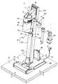
도 1은 본 발명의 일 실시예에 따른 청소장치의 사시도이다.
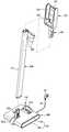
도 2는 도 1에 도시된 청소기 거치장치를 도시한 도면이다.
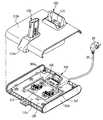
도 3은 도 2에 도시된 청소기 거치장치를 분해하여 도시한 도면이다.
도 4는 도 3에 도시된 청소기 거치장치의 베이스의 내부를 도시한 도면이다.
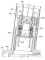
도 5는 도 3에 도시된 거치대와 지지대가 연결되는 부분의 단면을 도시한 도면이다.
도 6은 도 3에 도시된 지지대와 베이스가 연결되는 부분의 단면을 도시한 도면이다.
도 7은 도 2에 도시된 청소기 거치장치의 충전을 위한 구성들을 개략적으로 도시한 블록도이다.1 is a perspective view of a cleaning apparatus according to an embodiment of the present invention.
2 is a view showing the cleaner mounting apparatus shown in FIG.
3 is an exploded view illustrating the cleaner mounting apparatus illustrated in FIG. 2.
4 is a view showing the inside of the base of the cleaner mounting apparatus shown in FIG.
FIG. 5 is a diagram illustrating a cross section of a portion where the cradle and the support illustrated in FIG. 3 are connected.
FIG. 6 is a cross-sectional view of a portion where the support and the base shown in FIG. 3 are connected.
FIG. 7 is a block diagram schematically illustrating components for charging the cleaner mounting apparatus of FIG. 2.
본 명세서에 기재된 실시예와 도면에 도시된 구성은 개시된 발명의 바람직한 일 예에 불과할 뿐이며, 본 출원의 출원시점에 있어서 본 명세서의 실시예와 도면을 대체할 수 있는 다양한 변형 예들이 있을 수 있다.Configurations shown in the embodiments and drawings described herein are only exemplary embodiments of the disclosed invention, there may be various modifications that can replace the embodiments and drawings of the present specification at the time of filing of the present application.
또한, 본 명세서의 각 도면에서 제시된 동일한 참조번호 또는 부호는 실질적으로 동일한 기능을 수행하는 부품 또는 구성요소를 나타낸다.In addition, the same reference numerals or signs given in each drawing of the present specification represent parts or components that perform substantially the same function.
또한, 본 명세서에서 사용한 용어는 실시예를 설명하기 위해 사용된 것으로, 개시된 발명을 제한 및/또는 한정하려는 의도가 아니다. 단수의 표현은 문맥상 명백하게 다르게 뜻하지 않는 한, 복수의 표현을 포함한다. 본 명세서에서, "포함하다" 또는 "가지다"등의 용어는 명세서상에 기재된 특징, 숫자, 단계, 동작, 구성요소, 부품 또는 이들을 조합한 것이 존재함을 지정하려는 것이지, 하나 또는 그 이상의 다른 특징들이나 숫자, 단계, 동작, 구성요소, 부품 또는 이들을 조합한 것들의 존재 또는 부가 가능성을 미리 배제하지 않는다.Also, the terminology used herein is for the purpose of describing particular embodiments only and is not intended to be limiting and / or limiting the disclosed invention. Singular expressions include plural expressions unless the context clearly indicates otherwise. As used herein, the terms "comprise" or "having" are intended to indicate that there is a feature, number, step, action, component, part, or combination thereof described on the specification, one or more other features It does not preclude the existence or addition of numbers or steps, operations, components, parts or combinations thereof.
또한, 본 명세서에서 사용한 "제1", "제2" 등과 같이 서수를 포함하는 용어는 다양한 구성요소들을 설명하는데 사용될 수 있지만, 상기 구성요소들은 상기 용어들에 의해 한정되지는 않으며, 상기 용어들은 하나의 구성요소를 다른 구성요소로부터 구별하는 목적으로만 사용된다. 예를 들어, 본 발명의 권리 범위를 벗어나지 않으면서 제1 구성요소는 제2 구성요소로 명명될 수 있고, 유사하게 제2 구성요소도 제1 구성요소로 명명될 수 있다. "및/또는"이라는 용어는 복수의 관련된 기재된 항목들의 조합 또는 복수의 관련된 기재된 항목들 중의 어느 항목을 포함한다.In addition, terms including ordinal numbers such as “first”, “second”, and the like used in the present specification may be used to describe various components, but the components are not limited by the terms, and the terms are It is used only to distinguish one component from another. For example, without departing from the scope of the present invention, the first component may be referred to as the second component, and similarly, the second component may also be referred to as the first component. The term “and / or” includes any combination of a plurality of related items or any of a plurality of related items.
한편, 하기의 설명에서 사용된 용어 "상부", "하부", 및 "전후방향" 등은 도면을 기준으로 정의한 것이며, 이 용어에 의하여 각 구성요소의 형상 및 위치가 제한되는 것은 아니다.On the other hand, the terms "upper", "lower", and "front and back" and the like used in the following description are defined based on the drawings, and the shape and position of each component are not limited by this term.
이하에서는 본 발명에 따른 실시예를 첨부된 도면을 참조하여 상세히 설명한다.Hereinafter, with reference to the accompanying drawings an embodiment according to the present invention will be described in detail.
도 1은 본 발명의 일 실시예에 따른 청소장치의 사시도이다.1 is a perspective view of a cleaning apparatus according to an embodiment of the present invention.
도 1을 참조하면, 청소장치(1)는 청소기(10)와, 청소기 거치장치(100)를 포함할 수 있다.Referring to FIG. 1, the
청소기(10)는 청소기 본체(11)와, 청소기 본체(11)에 분리 가능하게 결합되는 연장관(16)과, 연장관(16)에 분리 가능하게 결합되는 메인 흡입유닛(12)과, 청소기 본체(11)에 분리 가능하게 결합되는 집진장치(13)를 포함할 수 있다.The
청소기 본체(11)는 피청소면 상의 이물질을 흡입하는데 필요한 흡입력을 발생시키는 흡입모터(미도시)와, 피청소면으로부터 흡입된 이물질이 수용되는 집진장치(13)를 포함할 수 있다.The
집진장치(13)는 흡입모터보다 공기유동의 상류에 배치되어 메인 흡입유닛(12)을 통해 유입되는 공기중의 먼지나 오물을 걸러내어 모아지도록 구성될 수 있다. 집진장치(13)는 청소기 본체(11)로부터 분리 가능하게 마련될 수 있다.The dust collecting device 13 may be disposed upstream of the air flow rather than the suction motor to filter and collect dust or dirt in the air flowing through the
청소기(10)는 필터 하우징(13a)을 포함할 수 있다. 필터 하우징(13a)은 대략 도넛 형상으로 마련되어 내부에 필터(미도시)를 수용할 수 있다. 필터의 종류에는 제한이 없으나, 일례로, 헤파 필터(Hepa Filter)가 필터 하우징(13a)의 내부에 배치될 수 있다. 필터는 집진장치(13)에서 걸러지지 않은 초미세먼지 등을 필터링할 수 있다. 필터 하우징(13a)은 필터를 통과한 공기가 청소기(10)의 외부로 배출되도록 복수의 홀(13b)을 포함할 수 있다.The
청소기 본체(11)는 사용자가 파지하여 청소기(10)를 조작할 수 있도록 핸들(14)을 포함할 수 있다. 사용자는 핸들(14)을 잡고, 청소기(10)를 전후방향으로 이동시킬 수 있다.The
청소기 본체(11)는 조작부(15)를 포함할 수 있다. 사용자는 조작부(15)에 마련된 전원버튼등을 조작하여 청소기(10)를 온/오프시키거나 흡입강도를 조절할 수 있다.The
메인 흡입유닛(12)은 피청소면과 접촉하도록 구성될 수 있다. 메인 흡입유닛(12)은 피청소면에 접촉하여 피청소면에 존재하는 먼지등의 이물질을 흡입하도록 마련될 수 있다.The
메인 흡입유닛(12)과 청소기 본체(11)는 연장관(16)에 의해 연결될 수 있다. 연장관(16)의 일 단은 메인 흡입유닛(12)에 피봇 연결되어, 메인 흡입유닛(12)이 연장관(16)에 대해 관절 운동할 수 있도록 구성될 수 있다.The
연장관(16)은 제1 연장관(16a)과 제2 연장관(16b)과 길이조절부(16c)를 포함할 수 있다. 길이조절부(16c)는 제2 연장관(16b)이 외부로 노출되는 길이를 조절하도록 마련될 수 있다. 길이조절부(16c)가 연장관(16)의 전체 길이를 조절함에 따라, 사용자는 적절한 길이의 연장관(16)으로 청소 작업을 수용할 수 있다. 따라서, 청소기(10)의 사용의 편의성이 향상될 수 있다.The
청소기 본체(11)는 연장관 연결부(11a)를 포함할 수 있다. 연장관 연결부(11a)는 연장관(16)을 청소기 본체(11)로부터 분리하거나 청소기 본체(11)에 결합하도록 마련될 수 있다.The
연장관(16)의 청소기 본체(11)와 연결된 일 단부와 반대되는 타 단부에는 흡입유닛 연결부(16d)가 마련될 수 있다. 흡입유닛 연결부(16d)는 메인 흡입유닛(12)을 청소기 본체(11)로부터 분리하거나 청소기 본체(11)에 결합하도록 마련될 수 있다. 흡입유닛 연결부(16d)에는 보조 흡입유닛(17a, 17b)이 분리 가능하게 결합될 수 있다.A suction
청소기(10)는 피청소면의 상태에 따라 메인 흡입유닛(12)을 보조 흡입유닛(17a, 17b)으로 교체할 수 있다. 일례로, 보조 흡입유닛(17a, 17b)은 브러시를 포함하여 구성된 보조 흡입유닛(17a)일 수 있으며, 좁은 틈을 청소하기 위해 입구가 좁게 형성된 형상으로 마련된 보조 흡입유닛(17b)일 수 있다.The cleaner 10 may replace the
이러한 보조 흡입유닛(17a, 17b)은 미 사용시 청소기 거치장치(100)의 연결포트(129)에 보관될 수 있다. 연결포트(129)는 지지대(120)에 마련될 수 있다. 연결포트(129)는 지지대(120)의 연장바디(121)로부터 후방으로 돌출되도록 형성되어, 다양한 종류의 보조 흡입유닛(17a, 17b)을 꽂아서 보관할 수 있다.The
청소기(10)는 청소기(10)에 구동력을 제공하도록 마련되는 제1 배터리(19)를 포함할 수 있다. 제1 배터리(19)는 청소기 본체(11)에 분리 가능하게 장착될 수 있다. 제1 배터리(19)는 청소기 거치장치(100)에 마련되는 제1 충전단자(133)와 전기적으로 연결될 수 있다. 제1 배터리(19)는 청소기 거치장치(100)에 마련되는 제1 충전단자(133)로부터 전력을 공급받아 충전될 수 있다.The cleaner 10 may include a
청소장치(1)는 제2 배터리(20)를 포함할 수 있다. 제2 배터리(20)는 여분의 배터리로서, 사용자는 청소기(10)에 장착된 제1 배터리(19)가 소진된 후, 제1 배터리(19)를 제2 배터리(20)로 교체한 후 청소 작업을 계속해서 수행할 수 있다. 이에 따라, 청소기(10)는 동작 시간이 증가될 수 있다.The
청소기 거치장치(100)는 청소기(10)가 보관 또는 거치될 수 있도록 구성될 수 있다. 청소기(10)는 청소기 거치장치(100)에서 충전될 수 있다. 청소기 거치장치(100)는 바닥면(30)에 배치되는 베이스(110)를 통해 바닥면(30)으로부터 지지될 수 있다.The
청소기 거치장치(100)는 일 단에 플러그(22)가 마련된 전원 케이블(21)을 통해 전력을 공급받을 수 있다. 전원 케이블(21)은 청소기 거치장치(100)의 베이스(110)의 하부에 마련된 전원 입력포트(119)와 연결될 수 있다. 플러그(22)는 콘센트(미도시)와 연결될 수 있다. 콘센터로부터 공급된 외부 전력은 플러그(22)와 전원 케이블(21)과, 전원 입력포트(119)를 순차적으로 거쳐 제1 전원 어댑터(116) 및 제2 전원 어댑터(117)에 각각 공급될 수 있다.The
도 2는 도 1에 도시된 청소기 거치장치를 도시한 도면이다. 도 3은 도 2에 도시된 청소기 거치장치를 분해하여 도시한 도면이다. 도 4는 도 3에 도시된 청소기 거치장치의 베이스의 내부를 도시한 도면이다. 도 5는 도 3에 도시된 거치대와 지지대가 연결되는 부분의 단면을 도시한 도면이다. 도 6은 도 3에 도시된 지지대와 베이스가 연결되는 부분의 단면을 도시한 도면이다. 도 7은 도 2에 도시된 청소기 거치장치의 충전을 위한 구성들을 개략적으로 도시한 블록도이다.2 is a view showing the cleaner mounting apparatus shown in FIG. 3 is an exploded view illustrating the cleaner mounting apparatus illustrated in FIG. 2. 4 is a view showing the inside of the base of the cleaner mounting apparatus shown in FIG. FIG. 5 is a diagram illustrating a cross section of a portion where the cradle and the support illustrated in FIG. 3 are connected. FIG. 6 is a cross-sectional view of a portion where the support and the base shown in FIG. 3 are connected. FIG. 7 is a block diagram schematically illustrating components for charging the cleaner mounting apparatus of FIG. 2.
도 2 및 도 3을 참조하면, 청소기 거치장치(100)는 청소기(10)가 보관 또는 충전될 수 있도록 구성될 수 있다. 청소기 거치장치(100)에는 청소기(10)가 거치될 수 있다. 청소기 거치장치(100)는 베이스(110)와, 지지대(120)와, 거치대(130)를 포함할 수 있다.2 and 3, the
베이스(110)는 청소기 거치장치(100)가 바닥면(30)에 대해 지지될 수 있도록 바닥면(30)과 대략 평행한 방향으로 연장될 수 있다. 베이스(110)는 베이스 커버(111)와, 배터리 수용부(112)를 포함할 수 있다.The base 110 may extend in a direction substantially parallel to the
도 4를 참조하면, 베이스 커버(111)는 베이스(110)의 외관을 형성할 수 있다. 베이스 커버(111)는 내부에 형성되는 수용공간(111a)을 가질 수 있다. 수용공간(111a)에는 인쇄회로기판(115, Printed Circuit Board, PCB)과, 제1 전원 어댑터(116)와, 제2 전원 어댑터(117)가 배치될 수 있다. 베이스 커버(111)는 상부 커버(111b)와 하부 커버(111c)를 포함할 수 있다. 수용공간(111a)은 상부 커버(111b)와 하부 커버(111c) 사이에 형성될 수 있다.Referring to FIG. 4, the
베이스 커버(111)는 청소기(10)가 청소기 거치장치(100)에 거치된 때, 청소기(10)에 장착된 메인 흡입유닛(12)을 안정적으로 지지하기 위한 흡입유닛 안착부(111d)를 포함할 수 있다. 메인 흡입유닛(12)은 흡입유닛 안착부(111d)에 안착된 상태로 청소기 거치장치(100)에 보관될 수 있다.The
배터리 수용부(112)는 청소기(10)에 장착되지 않은 여분의 제2 배터리(20)를 수용할 수 있도록 마련될 수 있다. 배터리 수용부(112)의 내부에는 제2 충전단자(113)가 배치될 수 있다. 제2 배터리(20)는 배터리 수용부(112)에 안착된 상태로 제2 충전단자(113)로부터 전력을 공급받을 수 있다.The
제2 충전단자(113)는 제2 배터리(20)가 배터리 수용부(112)에 수용된 때, 제2 배터리(20)와 전기적으로 연결될 수 있도록 마련될 수 있다. 제2 충전단자(113)는 제2 전원 어댑터(117)로부터 공급받은 전력을 제2 배터리(20)에 제공할 수 있다.The
인쇄회로기판(115)은 제1 전원 어댑터(116)와 제2 전원 어댑터(117)를 제어하도록 구성될 수 있다. 인쇄회로기판(115)은 제1 전원 어댑터(116)와 제2 전원 어댑터(117)가 동시에 구동되도록 제어할 수 있다. 인쇄회로기판(115)은 전원 케이블(21)을 통해 제공된 전력을 제1 전원 어댑터(116) 및 제2 전원 어댑터(117) 모두에 공급하여, 제1 충전단자(133)에 전기적으로 연결된 청소기(10)의 제1 배터리(19)를 충전함과 동시에, 제2 충전단자(113)에 전기적으로 연결된 청소기(10)의 제2 배터리(20)도 충전하도록 마련될 수 있다.The printed
제1 전원 어댑터(116)는 제1 충전단자(133)에 전력을 공급하도록 마련될 수 있다. 제1 전원 어댑터(116)는 전원 케이블(21)을 통해 제공된 전력을 전원 입력포트(119)를 통해 전달받을 수 있다. 제1 전원 어댑터(116)는 전원 입력포트(119)를 통해 전달받은 전력을 변환하여 연결된 전선의 일부(101a)로 전달할 수 있다. 제1 전원 어댑터(116)는 인쇄회로기판(115)에 의해 제어될 수 있다.The
제2 전원 어댑터(117)는 제2 충전단자(113)에 전력을 공급하도록 마련될 수 있다. 제2 전원 어댑터(117)는 전원 케이블(21)을 통해 제공된 전력을 전원 입력포트(119)를 통해 전달받을 수 있다. 제2 전원 어댑터(117)는 전원 입력포트(119)를 통해 전달받은 전력을 변환하여 제2 충전단자(113)로 제공할 수 있다. 제2 전원 어댑터(117)는 인쇄회로기판(115)에 의해 제어될 수 있다.The
제1 전원 어댑터(116)는 제2 전원 어댑터(117)와 독립적으로 구동 가능하게 마련될 수 있다.The
구체적으로, 도 7을 참조하면, 전원 케이블(21)을 통해 외부 전력이 전원 입력포트(119)로 공급된 때, 인쇄회로기판(115)은 전원 입력포트(119)를 통해 공급된 전력을 제1 전원 어댑터(116) 및 제2 전원 어댑터(117)로 공급할 수 있다. 제1 전원 어댑터(116)와 제2 전원 어댑터(117)는 각각 별도로 인쇄회로기판(115)과 전기적으로 연결되므로, 제1 전원 어댑터(116)와 제2 전원 어댑터(117)는 독립적으로 구동될 수 있다. 이러한 구성에 따라, 제1 전원 어댑터(116)는 제1 충전단자(133)로 전력을 공급하여 청소기(10)에 장착된 제1 배터리(19)를 충전할 수 있으며, 제2 전원 어댑터(117)는 제2 충전단자(113)로 전력을 공급하여 배터리 수용부(112)에 장착된 제2 배터리(20)를 충전할 수 있다.Specifically, referring to FIG. 7, when external power is supplied to the
베이스 커버(111)의 수용공간(111c)에는 베이스(110)의 중량을 증가시키도록 마련되는 웨이트 밸런서(118)가 배치될 수 있다. 웨이트 밸런서(118)는 베이스(110)의 중량을 증가시켜 청소기 거치장치(100)의 무게중심을 더욱 하측으로 배치시킬 수 있다. 이에 따라, 청소기 거치장치(100)는 바닥면에 대해 안정적으로 지지될 수 있다.The
지지대(120)는 베이스(110)와 거치대(130)를 연결하도록 마련될 수 있다. 지지대(120)는 내부에 중공(121a)이 형성된 연장바디(121)를 포함할 수 있다. 연장바디(121)의 일 단은 베이스(110)에 분리 가능하게 고정될 수 있다. 연장바디(121)의 일 단과 반대되는 타 단은 거치대(130)에 분리 가능하게 고정될 수 있다.
연장바디(121)는 베이스(110)가 배치되는 바닥면에 대해 경사진 방향으로 연장될 수 있다. 연장바디(121)는 베이스(110)의 상면의 가장자리로부터 베이스(110)의 중앙을 향해 상향 연장될 수 있다. 연장바디(121)는 베이스(110)의 상면의 선단으로부터 후방으로 갈수록 상향 경사지게 마련될 수 있다. 이에 따라, 청소기 거치장치(100)는 청소기(10)가 거치된 상태에서도 청소기(10)의 하중에 의해 안정적으로 바닥면에 대해 지지될 수 있다.The
연장바디(121)의 내부에 형성된 중공(121a)에는 제1 전원 어댑터(116)와 제1 충전단자(133)를 전기적으로 연결하는 전선의 일부(101b, 101c, 101d)가 배치될 수 있다. 제1 전원 어댑터(116)로부터 연장되는 전선(101a, 101b, 101c, 101d)은 중공(121a)을 통해 제1 충전단자(133)까지 안내될 수 있다.In the hollow 121a formed in the
연장바디(121)와 거치대(130)가 연결되는 부분에는 제1 연결장치(141)가 배치될 수 있다. 제1 연결장치(141)는 거치대(130)에 마련될 수 있다. 제1 연결장치(141)는 지지대(120)의 연장바디(121)에 삽입되어 고정될 수 있다.The
구체적으로, 도 5를 참조하면, 제1 연결장치(141)는 중공(121a)으로부터 거치대(130)로 연장되는 전선의 적어도 일부(101c, 101d)를 가이드하는 제1 전선 가이드(143)를 포함할 수 있다. 제1 전선 가이드(143)는 중공(121a)으로부터 연장되는 전선의 일부(101c, 101d)를 거치대(130)의 제1 충전단자(133)로 가이드할 수 있다.Specifically, referring to FIG. 5, the first connecting
구체적으로, 제1 전선 가이드(143)는 중공(121a)에 배치된 전선의 일부(101c)와 전기적으로 연결되는 제1 단자부(143a)와, 거치대(130)를 향해 연장되는 전선의 일부(101d)와 전기적으로 연결되는 제2 단자부(143b)와, 제1 단자부(143a) 및 제2 단자부(143b)를 전기적으로 연결하는 제1 연결부(143c)를 포함할 수 있다. 이에 따라, 중공(121a)에 배치된 전선의 일부(101c)와 거치대(130)를 향해 연장되는 전선의 일부(101d)는 전기적으로 연결될 수 있다.Specifically, the
연장바디(121)와 베이스(110)가 연결되는 부분에는 제2 연결장치(142)가 배치될 수 있다. 제2 연결장치(142)는 베이스(110)에 마련될 수 있다. 제2 연결장치(142)는 지지대(120)의 연장바디(121)에 삽입되어 고정될 수 있다.The
구체적으로, 도 6을 참조하면, 제2 연결장치(142)는 베이스(110)로부터 중공(121a)으로 연장되는 전선의 적어도 일부(101b, 101c)를 가이드하는 제2 전선 가이드(144)를 포함할 수 있다. 제2 전선 가이드(144)는 베이스(110)의 제1 전원 어댑터(116)로부터 연장되는 전선의 일부(101a)를 지지대(120)의 중공(121a)으로 가이드할 수 있다.Specifically, referring to FIG. 6, the second connecting
구체적으로, 제2 전선 가이드(144)는 제1 전원 어댑터(116)로부터 중공(121a)을 향해 연장되는 전선의 일부(101b)와 전기적으로 연결되는 제3 단자부(144a)와, 중공(121a)의 내부에서 거치대(130)를 향해 연장되는 전선의 일부(101c)와 전기적으로 연결되는 제4 단자부(144b)와, 제3 단자부(144a) 및 제4 단자부(144b)를 전기적으로 연결하는 제2 연결부(144c)를 포함할 수 있다. 이에 따라, 제1 전원 어댑터(116)로부터 연장된 전선의 일부(101b)와 중공(121a)의 내부로부터 거치대(130)를 향해 연장되는 전선의 일부(101c)는 전기적으로 연결될 수 있다.Specifically, the
지지대(120)는 보조 흡입유닛(17a, 17b)을 보관할 수 있도록 마련되는 연결포트(129)를 ej 포함할 수 있다. 연결포트(129)는 보조 흡입유닛(17a, 17b)이 삽입될 수 있도록 마련될 수 있다. 도 2에서 연결포트(129)는 2개 마련되는 것으로 도시되어 있으나, 연결포트(129)의 개수는 이에 제한되지 않고, 보조 흡입유닛(17a, 17b)의 개수에 대응될 수 있도록 다양하게 마련될 수 있다. 연결포트(129)는 사용자의 접근성을 고려하여 지지대(120)의 연장바디(121)의 상단부에서 후방으로 돌출될 수 있다.The
거치대(130)는 청소기(10)를 보관할 수 있도록 마련된다. 거치대(130)는 청소기(10)가 안착되는 청소기 안착부(131)와, 청소기(10)에 장착된 제1 배터리(19)가 안착되는 가이드 안착부(132)와, 청소기(10)와 전기적으로 연결 가능하도록 마련되는 제1 충전단자(133)를 포함할 수 있다.The
청소기 안착부(131)는 청소기(10)가 거치되도록 마련될 수 있다. 청소기 안착부(131)에는 청소기 본체(11)의 일 부분과 제1 배터리(19)가 안착될 수 있다. 청소기 안착부(131)에는 제1 충전단자(133)가 배치될 수 있다.The
가이드 안착부(132)는 청소기(10)가 안착될 때, 청소기(10)에 장착된 제1 배터리(19)를 제1 충전단자(133)와 전기적으로 연결되는 위치로 가이드할 수 있다. 가이드 안착부(132)는 제1 배터리(19)의 양 측단부를 청소기(10)가 청소기 안착부(131)에 삽입되는 방향으로 안내할 수 있다. 가이드 안착부(132)는 제1 배터리(132)에 대응되는 형상 및/또는 크기로 마련될 수 있다.When the cleaner 10 is seated, the
제1 충전단자(133)는 청소기 안착부(131)의 내측면으로부터 돌출되도록 마련될 수 있다. 제1 충전단자(133)는 청소기(10)가 거치대(130)에 거치되어 보관될 때, 청소기(10)에 장착된 제1 배터리(19)와 전기적으로 연결되도록 배치될 수 있다. 제1 충전단자(133)는 제1 전원 어댑터(116)로부터 공급받은 전력을 제1 배터리(19)에 제공할 수 있다. 제1 전원 어댑터(116)에서 변환된 전력은 전선(101a, 101b, 101c, 101d)을 통해 제1 충전단자(133)로 공급될 수 있다.The
이상에서는 특정의 실시예에 대하여 도시하고 설명하였다. 그러나, 상기한 실시예에만 한정되지 않으며, 발명이 속하는 기술분야에서 통상의 지식을 가진 자라면 이하의 청구범위에 기재된 발명의 기술적 사상의 요지를 벗어남이 없이 얼마든지 다양하게 변경 실시할 수 있을 것이다.In the above, specific embodiments have been illustrated and described. However, the present invention is not limited to the above-described embodiments, and those skilled in the art may make various changes without departing from the spirit of the technical idea of the invention as set forth in the claims below. .
1; 청소장치
10; 청소기
19; 제1 배터리
20; 제2 배터리
21; 전원 케이블
100; 청소기 거치장치
110; 베이스
113; 제2 충전단자
115; 인쇄회로기판
116; 제1 전원 어댑터
117; 제2 전원 어댑터
119; 전원 입력포트
120; 지지대
130; 거치대
133; 제1 충전단자One; Cleaning device
10; vacuum cleaner
19; First battery
20; Secondary battery
21; Power cable
100; Vacuum cleaner
110; Base
113; 2nd charging terminal
115; Printed circuit board
116; First power adapter
117; Second power adapter
119; Power input port
120; support fixture
130; holder
133; 1st charging terminal
Claims (20)
Translated fromKorean제2 배터리와 전기적으로 연결 가능하도록 마련되는 제2 충전단자를 포함하며, 상기 제1 충전단자에 전력을 공급하도록 마련되는 제1 전원 어댑터 및 상기 제2 충전단자에 전력을 공급하도록 마련되는 제2 전원 어댑터를 수용하도록 마련되는 베이스; 및
상기 거치대와 상기 베이스를 연결하며, 내부에 전선이 수용되는 중공이 형성되는 지지대;를 포함하며,
상기 거치대는 상기 지지대의 전선을 상기 제1 충전단자로부터 연장되는 전선과 전기적으로 연결하도록 마련되는 제1 연결부를 포함하고,
상기 베이스는 상기 지지대의 전선을 상기 제1 전원 어댑터로부터 연장되는 전선과 전기적으로 연결하도록 마련되는 제2 연결부를 포함하는 청소기 거치장치.A cradle including a first charging terminal provided to be electrically connected to a cleaner equipped with a first battery;
A second charging terminal provided to be electrically connected to a second battery, the first power adapter provided to supply power to the first charging terminal, and the second charging terminal to supply power to the second charging terminal; A base provided to receive a power adapter; And
And a support connecting the cradle to the base and having a hollow in which an electric wire is received.
The cradle includes a first connection portion provided to electrically connect the wire of the support with the wire extending from the first charging terminal,
And the base includes a second connection part provided to electrically connect the wire of the support with the wire extending from the first power adapter.
상기 거치대는 상기 지지대와 연결되는 제1 연결장치를 포함하며,
상기 제1 연결부는 상기 제1 연결장치에 배치되는 청소기 거치장치.The method of claim 1,
The cradle includes a first connecting device connected to the support,
The first connecting portion cleaner mounting apparatus disposed on the first connecting device.
상기 베이스는 상기 지지대와 연결되는 제2 연결장치를 포함하며,
상기 제2 연결부는 상기 제2 연결장치에 배치되는 청소기 거치장치.The method of claim 1,
The base includes a second connecting device connected to the support,
The second connector is a cleaner holding device disposed on the second connection device.
상기 제2 전원 어댑터는 상기 제1 전원 어댑터와 독립적으로 구동 가능하게 마련되는 청소기 거치장치.The method of claim 1,
And the second power adapter is provided to be driven independently of the first power adapter.
상기 지지대는 상기 베이스가 배치되는 바닥면에 대해 경사진 방향으로 연장되는 청소기 거치장치.The method of claim 1,
The supporter is a cleaner holding device extending in the direction inclined with respect to the floor surface on which the base is disposed.
상기 지지대는 상기 베이스의 상면의 가장자리로부터 상기 베이스의 중앙을 향해 상향 연장되는 청소기 거치장치.The method of claim 6,
The support is a cleaner holding device extending upward from the edge of the upper surface of the base toward the center of the base.
상기 베이스의 내부에는 상기 제1 전원 어댑터와 상기 제2 전원 어댑터를 제어하도록 구성되는 인쇄회로기판(Printed Circuit Board)이 배치되는 청소기 거치장치.The method of claim 1,
And a printed circuit board configured to control the first power adapter and the second power adapter inside the base.
상기 베이스는 상기 베이스의 중량을 증가시키도록 마련된 웨이트 밸런서를 포함하는 청소기 거치장치.The method of claim 1,
And the base includes a weight balancer provided to increase the weight of the base.
상기 베이스는 상기 제2 배터리가 상기 제2 충전단자와 전기적으로 연결되도록 수용되는 배터리 수용부를 포함하는 청소기 거치장치.The method of claim 1,
And the base includes a battery accommodating part accommodated so that the second battery is electrically connected to the second charging terminal.
상기 거치대는 상기 청소기가 안착될 때, 상기 청소기에 장착된 상기 제1 배터리를 상기 제1 충전단자와 전기적으로 연결되는 위치로 가이드하는 가이드 안착부를 포함하는 청소기 거치장치.The method of claim 1,
The cradle includes a guide mounting portion for guiding the first battery mounted on the cleaner to a position electrically connected to the first charging terminal when the cleaner is seated.
상기 지지대는 상기 청소기의 보조 흡입유닛을 보관하도록 마련되는 연결포트를 포함하는 청소기 거치장치.The method of claim 1,
The supporter cleaner mounting apparatus including a connection port provided to hold the auxiliary suction unit of the cleaner.
상기 제1 전원 어댑터 및 상기 제2 전원 어댑터에 전력을 공급하도록 상기 베이스에 연결 가능하게 마련되며, 상기 베이스와 연결되는 일 단과 반대되는 타 단이 전원 전압을 전달받기 위한 플러그와 연결되는 전원 케이블;을 더 포함하는 청소기 거치장치.The method of claim 1,
A power cable provided to be connected to the base to supply power to the first power adapter and the second power adapter, the other end being opposite to one end connected to the base and connected to a plug for receiving a power voltage; Cleaner mounting device further comprising a.
상기 베이스는 상기 청소기에 장착된 메인 흡입유닛이 안착되도록 마련되는 흡입유닛 안착부를 포함하는 청소기 거치장치.The method of claim 1,
And the base includes a suction unit seating unit provided to mount the main suction unit mounted on the cleaner.
상기 청소기가 거치되는 청소기 거치장치;를 포함하며,
상기 청소기 거치장치는,
제1 배터리가 장착된 청소기와 전기적으로 연결 가능하도록 마련되는 제1 충전단자를 포함하는 거치대;
제2 배터리와 전기적으로 연결 가능하도록 마련되는 제2 충전단자를 포함하며, 상기 제1 충전단자에 전력을 공급하도록 마련되는 제1 전원 어댑터 및 상기 제2 충전단자에 전력을 공급하도록 마련되는 제2 전원 어댑터를 수용하도록 마련되는 베이스; 및
상기 거치대와 상기 베이스를 연결하며, 내부에 전선이 수용되는 중공이 형성되는 지지대;를 포함하며,
상기 거치대는 상기 지지대의 전선을 상기 제1 충전단자로부터 연장되는 전선과 전기적으로 연결하도록 마련되는 제1 연결부를 포함하고,
상기 베이스는 상기 지지대의 전선을 상기 제1 전원 어댑터로부터 연장되는 전선과 전기적으로 연결하도록 마련되는 제2 연결부를 포함하는 청소장치.A cleaner provided to install the main suction unit and the first battery; And
Includes; a cleaner holding device on which the cleaner is mounted,
The cleaner mounting device,
A cradle including a first charging terminal provided to be electrically connected to a cleaner equipped with a first battery;
A second charging terminal provided to be electrically connected to a second battery, the first power adapter provided to supply power to the first charging terminal, and the second charging terminal to supply power to the second charging terminal; A base provided to receive a power adapter; And
And a support connecting the cradle to the base and having a hollow in which an electric wire is received.
The cradle includes a first connection portion provided to electrically connect the wire of the support with the wire extending from the first charging terminal,
The base includes a cleaning device including a second connecting portion provided to electrically connect the wire of the support with the wire extending from the first power adapter.
상기 베이스의 내부에는 상기 제1 전원 어댑터와 상기 제2 전원 어댑터를 제어하도록 구성되는 인쇄회로기판이 배치되는 청소장치.The method of claim 15,
And a printed circuit board disposed inside the base to control the first power adapter and the second power adapter.
상기 인쇄회로기판은 상기 제1 전원 어댑터와 상기 제2 전원 어댑터가 동시에 구동되도록 제어 가능하게 마련되는 청소장치.The method of claim 17,
The printed circuit board is a cleaning device provided to be controllable to drive the first power adapter and the second power adapter at the same time.
상기 지지대는 상기 베이스가 배치되는 바닥면에 대해 경사진 방향으로 연장되는 청소장치.The method of claim 15,
The support is a cleaning device extending in the direction inclined with respect to the bottom surface on which the base is disposed.
제2 배터리와 전기적으로 연결 가능하도록 마련되는 제2 충전단자를 포함하는 베이스; 및
상기 거치대와 상기 베이스를 연결하며, 내부에 전선이 수용되는 중공이 형성되는 지지대;를 포함하며,
상기 베이스는,
상기 제1 충전단자에 전력을 공급하도록 마련되는 제1 전원 어댑터;
상기 제2 충전단자에 전력을 공급하도록 마련되는 제2 전원 어댑터; 및
상기 제1 전원 어댑터 및 상기 제2 전원 어댑터를 독립적으로 제어하도록 마련되는 인쇄회로기판;을 포함하고,
상기 거치대는 상기 지지대의 전선을 상기 제1 충전단자로부터 연장되는 전선과 전기적으로 연결하도록 마련되는 제1 연결부를 포함하고,
상기 베이스는 상기 지지대의 전선을 상기 제1 전원 어댑터로부터 연장되는 전선과 전기적으로 연결하도록 마련되는 제2 연결부를 포함하는 청소기 거치장치.A cradle including a first charging terminal provided to be electrically connected to a cleaner equipped with a first battery;
A base including a second charging terminal provided to be electrically connected to a second battery; And
And a support connecting the cradle to the base and having a hollow in which an electric wire is received.
The base is,
A first power adapter provided to supply power to the first charging terminal;
A second power adapter provided to supply power to the second charging terminal; And
And a printed circuit board provided to independently control the first power adapter and the second power adapter.
The cradle includes a first connection portion provided to electrically connect the wire of the support with the wire extending from the first charging terminal,
And the base includes a second connection part provided to electrically connect the wire of the support with the wire extending from the first power adapter.
Priority Applications (3)
| Application Number | Priority Date | Filing Date | Title |
|---|---|---|---|
| KR1020180102611AKR102061513B1 (en) | 2018-08-30 | 2018-08-30 | Stand for cleaner and cleaning device having the same |
| PCT/KR2019/007889WO2020045813A1 (en) | 2018-08-30 | 2019-06-28 | Vacuum cleaner holding apparatus and vacuum cleaning apparatus having same |
| US17/250,754US20210345848A1 (en) | 2018-08-30 | 2019-06-28 | Vacuum cleaner holding apparatus and vacuum cleaning apparatus having same |
Applications Claiming Priority (1)
| Application Number | Priority Date | Filing Date | Title |
|---|---|---|---|
| KR1020180102611AKR102061513B1 (en) | 2018-08-30 | 2018-08-30 | Stand for cleaner and cleaning device having the same |
Publications (1)
| Publication Number | Publication Date |
|---|---|
| KR102061513B1true KR102061513B1 (en) | 2020-01-02 |
Family
ID=69154965
Family Applications (1)
| Application Number | Title | Priority Date | Filing Date |
|---|---|---|---|
| KR1020180102611AActiveKR102061513B1 (en) | 2018-08-30 | 2018-08-30 | Stand for cleaner and cleaning device having the same |
Country Status (3)
| Country | Link |
|---|---|
| US (1) | US20210345848A1 (en) |
| KR (1) | KR102061513B1 (en) |
| WO (1) | WO2020045813A1 (en) |
Cited By (6)
| Publication number | Priority date | Publication date | Assignee | Title |
|---|---|---|---|---|
| WO2021143864A1 (en)* | 2020-01-16 | 2021-07-22 | 江苏美的清洁电器股份有限公司 | Storage station of vacuum cleaner, and vacuum cleaner device assembly |
| AU2020289821B2 (en)* | 2020-01-17 | 2021-12-16 | Lg Electronics Inc. | Cleaning apparatus |
| KR102392550B1 (en) | 2020-10-29 | 2022-04-28 | 오장근 | stick type wireless vacuum cleaner with automatic suction power control |
| CN115528760A (en)* | 2021-06-24 | 2022-12-27 | 浙江齐享科技有限公司 | Pedestal-based containment power supply system |
| CN116056616A (en)* | 2020-07-29 | 2023-05-02 | 尚科宁家运营有限公司 | surface cleaning equipment |
| KR20250029714A (en) | 2023-08-23 | 2025-03-05 | 엘지전자 주식회사 | auxiliary devices for vacuum cleaner |
Families Citing this family (9)
| Publication number | Priority date | Publication date | Assignee | Title |
|---|---|---|---|---|
| CN111885951B (en)* | 2018-02-09 | 2022-10-11 | 尚科宁家运营有限公司 | Accessory for surface treatment equipment |
| US11399675B2 (en) | 2018-07-31 | 2022-08-02 | Sharkninja Operating Llc | Upright surface treatment apparatus having removable pod |
| CN112869629A (en)* | 2019-11-29 | 2021-06-01 | 江苏美的清洁电器股份有限公司 | Storage seat and dust collector assembly with same |
| CN119769935A (en)* | 2019-12-31 | 2025-04-08 | 北京石头世纪科技股份有限公司 | A vacuum cleaner bracket assembly |
| WO2021177699A1 (en)* | 2020-03-03 | 2021-09-10 | 엘지전자 주식회사 | Vacuum cleaner station, vacuum cleaner system, and method for controlling vacuum cleaner station |
| KR20210128786A (en)* | 2020-04-17 | 2021-10-27 | 엘지전자 주식회사 | Docking station and dust removal syatem inclduing the same |
| USD990078S1 (en)* | 2020-09-02 | 2023-06-20 | Samsung Electronics Co., Ltd. | Vacuum cleaner |
| USD1067564S1 (en) | 2021-06-04 | 2025-03-18 | Sharkninja Operating Llc | Vacuum nozzle |
| USD1048613S1 (en)* | 2023-02-08 | 2024-10-22 | Suzhou Dibea Electrical Technology Co., Ltd | Dust collector |
Citations (8)
| Publication number | Priority date | Publication date | Assignee | Title |
|---|---|---|---|---|
| KR200165245Y1 (en)* | 1999-07-21 | 2000-02-15 | 주식회사동양아로나전자 | Handy vaccum cleaner |
| JP2001149289A (en) | 1999-09-13 | 2001-06-05 | Matsushita Electric Ind Co Ltd | Rechargeable vacuum cleaner |
| JP2014124443A (en)* | 2012-12-27 | 2014-07-07 | Iris Ohyama Inc | Vacuum cleaner |
| JP2014200379A (en) | 2013-04-02 | 2014-10-27 | アイリスオーヤマ株式会社 | Vacuum cleaner |
| JP2016131795A (en) | 2015-01-21 | 2016-07-25 | 株式会社東芝 | Electric vacuum cleaner |
| KR101653449B1 (en)* | 2014-08-21 | 2016-09-01 | 엘지전자 주식회사 | Vacuum cleaner |
| JP2018126396A (en) | 2017-02-09 | 2018-08-16 | 日立アプライアンス株式会社 | Charging stand for vacuum cleaner |
| US20180310789A1 (en) | 2016-01-20 | 2018-11-01 | Jiangsu Midea Cleaning Appliances Co., Ltd. | Charging stand for vacuum cleaner |
Family Cites Families (5)
| Publication number | Priority date | Publication date | Assignee | Title |
|---|---|---|---|---|
| KR101841455B1 (en)* | 2016-08-25 | 2018-05-04 | 엘지전자 주식회사 | Stand for Cleaner |
| KR102603585B1 (en)* | 2016-05-09 | 2023-11-20 | 엘지전자 주식회사 | Charging device for cleaner |
| WO2017196024A2 (en)* | 2016-05-09 | 2017-11-16 | 엘지전자 주식회사 | Cleaner holder |
| KR102519650B1 (en)* | 2017-03-03 | 2023-04-10 | 엘지전자 주식회사 | Supporting device for cleaner and cleaner unit |
| WO2020027452A1 (en)* | 2018-07-30 | 2020-02-06 | 엘지전자 주식회사 | Cleaner holder and cleaner unit |
- 2018
- 2018-08-30KRKR1020180102611Apatent/KR102061513B1/enactiveActive
- 2019
- 2019-06-28USUS17/250,754patent/US20210345848A1/ennot_activeAbandoned
- 2019-06-28WOPCT/KR2019/007889patent/WO2020045813A1/ennot_activeCeased
Patent Citations (8)
| Publication number | Priority date | Publication date | Assignee | Title |
|---|---|---|---|---|
| KR200165245Y1 (en)* | 1999-07-21 | 2000-02-15 | 주식회사동양아로나전자 | Handy vaccum cleaner |
| JP2001149289A (en) | 1999-09-13 | 2001-06-05 | Matsushita Electric Ind Co Ltd | Rechargeable vacuum cleaner |
| JP2014124443A (en)* | 2012-12-27 | 2014-07-07 | Iris Ohyama Inc | Vacuum cleaner |
| JP2014200379A (en) | 2013-04-02 | 2014-10-27 | アイリスオーヤマ株式会社 | Vacuum cleaner |
| KR101653449B1 (en)* | 2014-08-21 | 2016-09-01 | 엘지전자 주식회사 | Vacuum cleaner |
| JP2016131795A (en) | 2015-01-21 | 2016-07-25 | 株式会社東芝 | Electric vacuum cleaner |
| US20180310789A1 (en) | 2016-01-20 | 2018-11-01 | Jiangsu Midea Cleaning Appliances Co., Ltd. | Charging stand for vacuum cleaner |
| JP2018126396A (en) | 2017-02-09 | 2018-08-16 | 日立アプライアンス株式会社 | Charging stand for vacuum cleaner |
Cited By (7)
| Publication number | Priority date | Publication date | Assignee | Title |
|---|---|---|---|---|
| WO2021143864A1 (en)* | 2020-01-16 | 2021-07-22 | 江苏美的清洁电器股份有限公司 | Storage station of vacuum cleaner, and vacuum cleaner device assembly |
| AU2020289821B2 (en)* | 2020-01-17 | 2021-12-16 | Lg Electronics Inc. | Cleaning apparatus |
| US11426040B2 (en) | 2020-01-17 | 2022-08-30 | Lg Electronics Inc. | Cleaning apparatus |
| CN116056616A (en)* | 2020-07-29 | 2023-05-02 | 尚科宁家运营有限公司 | surface cleaning equipment |
| KR102392550B1 (en) | 2020-10-29 | 2022-04-28 | 오장근 | stick type wireless vacuum cleaner with automatic suction power control |
| CN115528760A (en)* | 2021-06-24 | 2022-12-27 | 浙江齐享科技有限公司 | Pedestal-based containment power supply system |
| KR20250029714A (en) | 2023-08-23 | 2025-03-05 | 엘지전자 주식회사 | auxiliary devices for vacuum cleaner |
Also Published As
| Publication number | Publication date |
|---|---|
| US20210345848A1 (en) | 2021-11-11 |
| WO2020045813A1 (en) | 2020-03-05 |
Similar Documents
| Publication | Publication Date | Title |
|---|---|---|
| KR102061513B1 (en) | Stand for cleaner and cleaning device having the same | |
| US10299651B2 (en) | Cleaner holder | |
| KR102295181B1 (en) | Holder for cleaner and cleaner unit | |
| KR101375653B1 (en) | Vacuum cleaner using for both upright and canister type cleaner | |
| CN110996737B (en) | Surface cleaning apparatus | |
| US11583156B2 (en) | Stand for cleaner and cleaning apparatus having the same | |
| KR20190021521A (en) | Cleaner | |
| JPH02224725A (en) | Dust-sucking brush nozzle for suction cleaner | |
| JP2020110472A (en) | Vacuum cleaner | |
| JP2022000285A (en) | Vacuum cleaner and vacuum cleaner storage | |
| JP2018015323A (en) | Electric cleaning device | |
| JP2023024828A (en) | vacuum cleaner set | |
| JP7068089B2 (en) | Vacuum cleaner charging stand | |
| JP2016131793A (en) | Vacuum cleaner | |
| KR20190018532A (en) | Battery-operated vacuum cleaner | |
| CN109316121B (en) | Electric vacuum cleaners, vacuum cleaner supports and electric vacuum cleaner equipment | |
| JP2017185036A (en) | Vacuum cleaner | |
| CN109171552B (en) | Cleaning tool | |
| US20060213024A1 (en) | Vacuum cleaner | |
| JP2018015325A (en) | Electric cleaning device | |
| KR20210020749A (en) | Stand for cleaner and cleaning device having the same | |
| JP2015054150A (en) | Vacuum cleaner | |
| WO2020262600A1 (en) | Electric vacuum cleaner | |
| CN115379785A (en) | Charging seat of electric dust collector | |
| CN112617656A (en) | Hand-held vacuum cleaner |
Legal Events
| Date | Code | Title | Description |
|---|---|---|---|
| PA0109 | Patent application | Patent event code:PA01091R01D Comment text:Patent Application Patent event date:20180830 | |
| PA0201 | Request for examination | Patent event code:PA02012R01D Patent event date:20190412 Comment text:Request for Examination of Application Patent event code:PA02011R01I Patent event date:20180830 Comment text:Patent Application | |
| PA0302 | Request for accelerated examination | Patent event date:20190412 Patent event code:PA03022R01D Comment text:Request for Accelerated Examination Patent event date:20180830 Patent event code:PA03021R01I Comment text:Patent Application | |
| PE0902 | Notice of grounds for rejection | Comment text:Notification of reason for refusal Patent event date:20190522 Patent event code:PE09021S01D | |
| PE0701 | Decision of registration | Patent event code:PE07011S01D Comment text:Decision to Grant Registration Patent event date:20190927 | |
| GRNT | Written decision to grant | ||
| PR0701 | Registration of establishment | Comment text:Registration of Establishment Patent event date:20191226 Patent event code:PR07011E01D | |
| PR1002 | Payment of registration fee | Payment date:20191227 End annual number:3 Start annual number:1 | |
| PG1601 | Publication of registration | ||
| PR1001 | Payment of annual fee | Payment date:20221129 Start annual number:4 End annual number:4 | |
| PR1001 | Payment of annual fee | Payment date:20231129 Start annual number:5 End annual number:5 | |
| PR1001 | Payment of annual fee | Payment date:20241128 Start annual number:6 End annual number:6 |