KR102061263B1 - System and method for controlling an electromagnetic coil system - Google Patents
System and method for controlling an electromagnetic coil systemDownload PDFInfo
- Publication number
- KR102061263B1 KR102061263B1KR1020170092668AKR20170092668AKR102061263B1KR 102061263 B1KR102061263 B1KR 102061263B1KR 1020170092668 AKR1020170092668 AKR 1020170092668AKR 20170092668 AKR20170092668 AKR 20170092668AKR 102061263 B1KR102061263 B1KR 102061263B1
- Authority
- KR
- South Korea
- Prior art keywords
- coil
- current
- magnetic field
- controlling
- coil system
- Prior art date
- Legal status (The legal status is an assumption and is not a legal conclusion. Google has not performed a legal analysis and makes no representation as to the accuracy of the status listed.)
- Active
Links
Images


Classifications
- A—HUMAN NECESSITIES
- A61—MEDICAL OR VETERINARY SCIENCE; HYGIENE
- A61B—DIAGNOSIS; SURGERY; IDENTIFICATION
- A61B1/00—Instruments for performing medical examinations of the interior of cavities or tubes of the body by visual or photographical inspection, e.g. endoscopes; Illuminating arrangements therefor
- A61B1/00147—Holding or positioning arrangements
- A61B1/00158—Holding or positioning arrangements using magnetic field
- A—HUMAN NECESSITIES
- A61—MEDICAL OR VETERINARY SCIENCE; HYGIENE
- A61B—DIAGNOSIS; SURGERY; IDENTIFICATION
- A61B1/00—Instruments for performing medical examinations of the interior of cavities or tubes of the body by visual or photographical inspection, e.g. endoscopes; Illuminating arrangements therefor
- G—PHYSICS
- G01—MEASURING; TESTING
- G01R—MEASURING ELECTRIC VARIABLES; MEASURING MAGNETIC VARIABLES
- G01R33/00—Arrangements or instruments for measuring magnetic variables
- G01R33/02—Measuring direction or magnitude of magnetic fields or magnetic flux
Landscapes
- Health & Medical Sciences (AREA)
- Life Sciences & Earth Sciences (AREA)
- Physics & Mathematics (AREA)
- Surgery (AREA)
- Biomedical Technology (AREA)
- Molecular Biology (AREA)
- Pathology (AREA)
- Radiology & Medical Imaging (AREA)
- Nuclear Medicine, Radiotherapy & Molecular Imaging (AREA)
- Engineering & Computer Science (AREA)
- Biophysics (AREA)
- Heart & Thoracic Surgery (AREA)
- Medical Informatics (AREA)
- Optics & Photonics (AREA)
- Animal Behavior & Ethology (AREA)
- General Health & Medical Sciences (AREA)
- Public Health (AREA)
- Veterinary Medicine (AREA)
- Condensed Matter Physics & Semiconductors (AREA)
- General Physics & Mathematics (AREA)
- Magnetic Resonance Imaging Apparatus (AREA)
- Plasma Technology (AREA)
Abstract
Translated fromKorean
Description
Translated fromKorean본 발명은 체내 도입 장치를 전자기 유도로 조종하는 코일시스템을 제어하는 장치 및 방법에 관한 것으로, 보다 상세하게는, 전자기 코일시스템이 체내 도입 장치를 정밀하게 조종할 수 있도록 코일시스템의 자기장을 균질하게 유지하게 하는 제어 장치 및 방법에 관한 것이다.The present invention relates to an apparatus and a method for controlling a coil system for controlling the induction apparatus by electromagnetic induction, and more particularly, to homogeneously adjust the magnetic field of the coil system so that the electromagnetic coil system can accurately control the induction apparatus. A control device and method for retaining.
체내 도입 장치의 대표적인 예로서 캡슐 내시경이 있다. 수술을 하지 않고 사람 또는 동물의 체내 장기의 상태를 촬영하거나 조직을 채취하거나 약물을 투입하는 등의 의료 행위를 하기 위해 내시경이 많이 사용되는데, 내시경은 튜브를 통해 체내에 투입되기 때문에 고통과 불편함이 있어서, 이러한 문제를 해결하고자 튜브가 없는 무선의 캡슐 내시경이 개발되어 의료 현장에서 사용되고 있다.Representative examples of the body introduction device include a capsule endoscope. Endoscopy is often used to perform medical activities such as taking pictures of the organs of a human or animal body, collecting tissues, or injecting drugs without surgery. Because endoscopes are introduced into the body through tubes, pain and discomfort In order to solve this problem, a tubeless wireless endoscope has been developed and used in the medical field.
캡슐 내시경은 환자가 삼킴으로써 체내에 도입되는데, 외부에서 캡슐 내시경의 이동을 제어하지 않고 캡슐 내시경이 자연적인 장기의 연동 운동으로 배출되는 방식이 있고, 외부에서 자기장으로 캡슐 내시경의 이동을 제어하여 필요한 체내 부위만 집중적으로 의료 행위를 하는 방식이 있다.The capsule endoscope is introduced into the body by swallowing the patient, and the capsule endoscope is discharged by natural organ peristalsis without controlling the movement of the capsule endoscope from the outside, and the capsule endoscope is controlled by the magnetic field from the outside. There is a way of intensive medical care only in the body.
캡슐 내시경 같은 체내 도입 장치를 전자기 유도로 조종하는 코일시스템은 일본특허 제5436447호에서와 같이 10개 내외의 코일로 구성된다. 코일시스템을 구성하는 각 코일은 체내 도입 장치를 조종하기 위해 각각의 역할이 있다. 예를 들면, 각 코일은 X, Y, Z 축상에서의 병진, 세차, 틸팅 등의 움직임을 각각 담당하며, 각 코일의 독립적인 역할을 조합하여 자유자재로 도입 장치를 조종할 수 있다. 따라서, 각 코일이 필요한 역할을 잘 수행하도록 하기 위해서는 각 코일의 자기장이 균질하게 형성이 되어야 한다.The coil system for controlling an induction device such as a capsule endoscope by electromagnetic induction is composed of about 10 coils as in Japanese Patent No. 5436447. Each coil constituting the coil system has its own role in controlling the body introduction device. For example, each coil is responsible for the translation, precession, tilting, and the like movement on the X, Y, Z axis, respectively, and can independently control the introduction device by combining the independent roles of each coil. Therefore, in order for each coil to perform the necessary role well, the magnetic field of each coil should be formed homogeneously.
자기장이 균질하게 형성되지 않고 오차나 왜곡이 발생하는 주요 원인으로 크게 두 가지가 있는데, 코일시스템의 동작 환경의 변화 및 사용 중 코일의 온도변화이다. 코일시스템의 동작 환경의 변화로는, 주변 온도의 변화 또는 전력 시스템의 출력 오차 등에 따른 자기장의 변화가 있다. 계절 변화 등의 이유로 주변 온도에 차이가 발생하면 코일의 임피던스가 변할 수 있고, 전력 시스템이 안정성이 낮으면 사용시마다 전류 제어에 오차가 발생할 수 있다. 따라서, 이러한 동작 환경의 변화로 자기장이 변하게 되면 체내 도입 장치의 움직임에 오차나 왜곡이 생기는 문제점이 있다.There are two main causes of the occurrence of errors or distortions without the formation of a homogeneous magnetic field: the change in the operating environment of the coil system and the change in temperature of the coil during use. As a change in the operating environment of the coil system, there is a change in the magnetic field due to the change in the ambient temperature or the output error of the power system. If there is a difference in the ambient temperature due to seasonal changes, the impedance of the coil may change, and if the power system is low in stability, an error may occur in current control every time it is used. Therefore, when the magnetic field is changed due to the change of the operating environment, there is a problem that an error or distortion occurs in the movement of the body introduction apparatus.
또한, 코일시스템은, 사용 중에 일정한 전압을 유지하도록 제어를 하게 되면, 코일이 온도가 상승하면서 코일의 임피던스가 차츰 변하게 되고, 시간이 지남에 따라 코일의 전류값이 작아져서 결국 자기장이 약해지는 상황이 발생하는 문제점이 있다.In addition, when the coil system is controlled to maintain a constant voltage during use, the coil's impedance gradually changes as the coil increases in temperature, and the coil's current value decreases over time, resulting in a weak magnetic field. There is a problem that occurs.
본 발명은 상기와 같은 종래 기술의 문제점을 해결하기 위해 창안된 것으로, 코일시스템의 자기장을 균질하게 유지하게 하여 전자기 코일시스템이 체내 도입 장치를 정밀하게 조종할 수 있도록 하는 제어 장치 및 방법에 관한 것이다.The present invention has been made to solve the above problems of the prior art, and relates to a control device and method for allowing the electromagnetic coil system to precisely control the body introduction device by maintaining the magnetic field of the coil system homogeneously. .
상기 기술적 과제를 달성하기 위한, 본 발명의 일 실시예에 따르면, 체내 도입 장치를 전자기 유도로 조종하는 코일시스템을 제어하는 장치로서, 상기 코일시스템의 각 코일의 자기장을 측정하는 자기장측정부; 상기 각 코일의 측정된 자기장에 기초하여 상기 각 코일의 전류 보정값을 추출하는 보정부; 및 상기 전류 보정값에 기초하여 상기 각 코일의 전류를 제어하는 전류제어부를 포함하는, 코일시스템 제어 장치가 제공된다.According to an embodiment of the present invention for achieving the above technical problem, an apparatus for controlling a coil system for controlling the body introduction apparatus by electromagnetic induction, comprising: a magnetic field measuring unit for measuring a magnetic field of each coil of the coil system; A correction unit extracting a current correction value of each coil based on the measured magnetic field of each coil; And a current control unit controlling a current of each coil based on the current correction value.
상기 전류제어부는, 상기 각 코일의 온도 변화에 따라 상기 각 코일의 임피던스가 변하더라도 상기 각 코일이 균질한 자기장을 형성하도록 전류를 제어하는 것일 수 있다.The current control unit may control the current so that each coil forms a homogeneous magnetic field even if the impedance of each coil changes according to the temperature change of each coil.
상기 보정부는, 상기 각 코일의 측정된 자기장을 보정하여 회귀(regression) 모형을 추출하고, 상기 각 코일의 미리 저장되어 있는 기준 모형 및 상기 각 코일의 추출된 회귀 모형에 기초하여 상기 전류 보정값을 추출할 수 있다.The correction unit corrects the measured magnetic field of each coil to extract a regression model, and calculates the current correction value based on a pre-stored reference model of each coil and the extracted regression model of each coil. Can be extracted.
상기 측정된 자기장은 상기 각 코일로부터 상기 도입 장치의 위치로 예상되는 지점에서 측정된 값일 수 있다.The measured magnetic field may be a value measured at a point expected from the respective coils to the position of the introduction device.
상기 자기장측정부는 복수의 전류값 또는 복수의 온도에서 자기장을 측정할 수 있다.The magnetic field measuring unit may measure the magnetic field at a plurality of current values or a plurality of temperatures.
상기 전류제어부는 상기 각 코일의 실시간 온도 변화에 기초하여 상기 전류 보정값을 선택할 수 있다.The current controller may select the current correction value based on a real-time temperature change of each coil.
상기 코일시스템 제어 장치는 상기 각 코일의 전류 변동값을 감지하는 전류측정부를 더 포함하되, 상기 전류제어부는 상기 감지된 전류 변동값에 기초하여 상기 각 코일의 전류를 제어할 수 있다.The coil system controller may further include a current measuring unit configured to detect a current variation value of each coil, wherein the current controller may control the current of each coil based on the sensed current variation value.
상기 자기장의 측정은 상기 도입 장치를 사용하기 전에 수행할 수 있다.The measurement of the magnetic field can be performed before using the introduction device.
상기 전류 변동값의 감지는 상기 도입 장치를 사용하는 중에 수행할 수 있다.The detection of the current fluctuation value can be performed while using the introduction device.
상기 기술적 과제를 달성하기 위한, 본 발명의 다른 일 실시예에 따르면, 체내 도입 장치를 전자기 유도로 조종하는 코일시스템을 제어하는 방법으로서, 상기 코일시스템의 각 코일의 자기장을 측정하는 단계; 상기 각 코일의 측정된 자기장에 기초하여 상기 각 코일의 전류 보정값을 추출하는 단계; 상기 각 코일의 전류 변동값을 감지하는 단계; 및 상기 전류 보정값 및 상기 감지된 전류 변동값에 기초하여 상기 각 코일의 전류를 제어하는 단계를 포함하는, 코일시스템 제어 방법이 제공된다.According to another embodiment of the present invention for achieving the above technical problem, a method for controlling a coil system for controlling the body introduction device by electromagnetic induction, comprising: measuring a magnetic field of each coil of the coil system; Extracting a current correction value of each coil based on the measured magnetic field of each coil; Detecting a current variation value of each coil; And controlling the current of each coil based on the current correction value and the sensed current variation value.
상기 전류를 제어하는 단계는, 상기 각 코일의 온도 상승에 따라 상기 각 코일의 임피던스가 변하더라도 상기 각 코일이 균질한 자기장을 형성하도록 전류를 제어할 수 있다.The controlling of the current may control the current so that each coil forms a homogeneous magnetic field even when the impedance of each coil changes as the temperature of each coil increases.
상기 전류 보정값을 추출하는 단계는, 상기 각 코일의 측정된 자기장을 보정하여 회귀 모형을 추출하는 단계; 및 상기 각 코일의 미리 저장되어 있는 기준 모형 및 상기 각 코일의 추출된 회귀 모형에 기초하여 상기 전류 보정값을 추출하는 단계를 포함할 수 있다.The extracting of the current correction value may include: extracting a regression model by correcting the measured magnetic field of each coil; And extracting the current correction value based on a pre-stored reference model of each coil and the extracted regression model of each coil.
상기 전류를 제어하는 단계는, 상기 각 코일의 온도 변화에 기초하여 상기 전류 보정값을 선택하는 단계를 포함할 수 있다.The controlling of the current may include selecting the current correction value based on a change in temperature of each coil.
이상과 같이, 본 발명에 따르면, 코일시스템을 각 코일별로 전류에 기반하여 동작시키되, 도입 장치의 사용 전에는 코일시스템의 각 코일의 동작 환경에 의한 왜곡된 자기장을 보정하여 전류 보정값을 추출하고, 도입 장치의 사용 중에는 각 코일의 온도 상승에 따라 각 코일의 임피던스가 변하더라도 각 코일이 일정한 자기장을 형성하도록 제어함으로써, 코일시스템의 자기장이 균질하게 유지되어 체내 도입 장치를 운전자가 의도한대로 정밀하게 조종할 수 있는 효과가 있다.As described above, according to the present invention, while operating the coil system based on the current for each coil, before using the introduction device to correct the distorted magnetic field by the operating environment of each coil of the coil system to extract the current correction value, While the introduction device is in use, even if the impedance of each coil changes as the temperature of each coil changes, the coils are controlled to form a constant magnetic field so that the magnetic field of the coil system remains homogeneous, thus precisely manipulating the introduction device as intended by the driver. It can work.
도 1은 본 발명의 일 실시예에 따른 전자기 코일시스템 제어 장치 및 주변 구성을 나타내는 도면이다.
도 2는 본 발명의 다른 일 실시예에 따른 전자기 코일시스템 제어 장치의 구성을 나타내는 블록도이다.
도 3은 본 발명의 또 다른 일 실시예에 따른 전자기 코일시스템 제어 장치 및 코일시스템의 구성을 나타내는 블록도이다.
도 4는 본 발명의 또 다른 일 실시예에 따른 코일시스템의 자기장 측정 위치를 나타내는 도면이다.
도 5는 본 발명의 또 다른 일 실시예에 따른 자기장 보정 과정을 설명하기 위한 그래프이다.
도 6은 본 발명의 또 다른 일 실시예에 따른 전자기 코일시스템 제어 방법에 대한 구체적인 일례를 나타내는 순서도이다.1 is a view showing the electromagnetic coil system control apparatus and the peripheral configuration according to an embodiment of the present invention.
Figure 2 is a block diagram showing the configuration of an electromagnetic coil system control apparatus according to another embodiment of the present invention.
3 is a block diagram showing the configuration of an electromagnetic coil system control apparatus and a coil system according to another embodiment of the present invention.
4 is a view showing a magnetic field measurement position of the coil system according to another embodiment of the present invention.
5 is a graph illustrating a magnetic field correction process according to another embodiment of the present invention.
6 is a flowchart illustrating a specific example of a method of controlling an electromagnetic coil system according to another exemplary embodiment of the present invention.
이하, 첨부한 도면을 참조하여 본 발명이 속하는 기술 분야에서 통상의 지식을 가진 자가 용이하게 실시할 수 있도록 본 발명의 실시예를 상세히 설명한다. 하기의 설명에서는 본 발명의 실시예에 따른 동작을 이해하는데 필요한 부분만이 도시되고 설명되며 그 이외 부분의 도시와 설명은 본 발명의 요지를 흐리지 않도록 생략하였다. 그러나 본 발명은 여러 가지 상이한 형태로 구현될 수 있으며 여기에서 설명하는 실시예에 한정되지 않는다.Hereinafter, exemplary embodiments of the present invention will be described in detail with reference to the accompanying drawings so that those skilled in the art may easily implement the present invention. In the following description, only parts necessary for understanding the operation according to the embodiment of the present invention are shown and described, and illustrations and descriptions of other parts are omitted so as not to obscure the subject matter of the present invention. As those skilled in the art would realize, the described embodiments may be modified in various different ways, all without departing from the spirit or scope of the present invention.
또한, 이하에서 설명되는 본 명세서 및 청구범위에 사용된 용어나 단어는 통상적이거나 사전적인 의미로 한정해서 해석되어서는 아니 되며, 본 발명을 가장 적절하게 표현할 수 있도록 본 발명의 기술적 사상에 부합하는 의미와 개념으로 해석되어야 한다.In addition, the terms or words used in the specification and claims described below are not to be construed as being limited to the ordinary or dictionary meaning, meaning that corresponds to the technical spirit of the present invention so as to best express the present invention To be interpreted as
명세서 전체에서, 어떤 부분이 다른 부분과 "연결"되어 있다고 할 때, 이는 "직접적으로 연결"되어 있는 경우만을 한정하는 것이 아니라, 그 중간에 다른 소자를 사이에 두고 "전기적으로 연결"되어 있는 경우도 포함한다. 또한, 어떤 부분이 어떤 구성요소를 "포함"한다고 할 때, 이는 특별히 반대되는 기재가 없는 한 다른 구성요소를 제외하는 것이 아니라 다른 구성요소를 더 포함할 수 있는 것을 의미한다.Throughout the specification, when a part is "connected" to another part, it is not limited to "directly connected", but is "electrically connected" with another element in between. Also includes. In addition, when a part is said to "include" a certain component, this means that it may further include other components, except to exclude other components unless otherwise stated.
설명의 간략함을 위해, 본 명세서에서는 예시를 들어 순서도 또는 플로우 차트의 형태로 하나 이상의 방법이 일련의 단계로서 도시되고 기술되어 있지만, 본 발명이 단계들의 순서에 의해 제한되지 않는데 그 이유는 본 발명에 따라 본 명세서에 도시되고 기술되어 있는 것과 다른 순서로 또는 다른 단계들과 동시에 행해질 수 있기 때문이라는 것을 잘 알 것이다. 또한, 예시된 모든 단계들이 본 발명에 따라 방법을 구현해야만 하는 것은 아닐 수 있다.For simplicity of explanation, although one or more methods are shown and described herein as a series of steps, for example in the form of a flowchart or flow chart, the present invention is not limited by the order of the steps, for the present invention. It will be appreciated that it may be done in a different order or simultaneously with other steps than shown and described herein. Moreover, not all illustrated steps may have to implement a methodology in accordance with the present invention.
본 발명의 다양한 실시예들을 설명함에 있어, 대응되는 구성요소에 대해서는 동일한 명칭 및 동일한 참조부호를 부여하여 설명하도록 한다. 본 발명의 실시예를 설명하기 위하여 참조하는 도면에서 구성요소의 크기나 선의 두께 등은 이해의 편의상 과장되게 표현되어 있을 수 있다.In describing various embodiments of the present disclosure, corresponding elements will be described with the same names and the same reference numerals. In the drawings referred to for describing the embodiment of the present invention, the size of the component, the thickness of the line, etc. may be exaggerated for convenience of understanding.
캡슐 내시경 등의 체내 도입 장치를 전자기 유도로 조종하는 코일시스템은 10개 내외의 코일로 구성되는데, 코일시스템을 구성하는 각 코일은 체내 도입 장치를 조종하기 위해 각각의 역할이 정해져 있다. 예를 들면, 각 코일은 X, Y, Z 축상에서의 병진, 세차, 틸팅 등의 움직임을 각각 담당하며, 각 코일의 독립적인 역할을 다양한 방법으로 조합하여 자유자재로 체내 도입 장치를 조종할 수 있도록 구성된다.The coil system for controlling the body introduction device such as capsule endoscope by electromagnetic induction is composed of about 10 coils, each of the coils constituting the coil system is assigned a role to control the body introduction device. For example, each coil is responsible for the translation, precession, tilting, and other movements on the X, Y, and Z axes, and can independently control the induction device by combining the independent roles of each coil in various ways. It is configured to be.
따라서, 각 코일이 필요한 역할을 잘 수행하도록 하기 위해서는 각 코일의 자기장이 균질하게 형성이 되어야 하는데, 코일시스템 주변 온도의 변화 또는 전력 시스템의 출력 오차 등에 따라 자기장의 변화나 왜곡이 발생할 수 있다. 계절 변화 등의 이유로 주변 온도에 차이가 발생하면 코일의 임피던스가 변할 수 있고, 전력 시스템이 안정성이 낮으면 사용시마다 전류 제어에 오차가 발생할 수 있으므로, 이러한 동작 환경 요인에 의한 자기장 오차를 최소화하기 위해, 코일시스템을 사용하기 직전에 자기장 보정을 해주는 것이 바람직하다.Therefore, in order for each coil to perform the necessary role well, the magnetic field of each coil should be homogeneously formed. The magnetic field may be changed or distorted due to the change in the ambient temperature of the coil system or the output error of the power system. The impedance of the coil may change when the ambient temperature is different due to seasonal changes, and when the power system is low in stability, an error may occur in the current control every time it is used. Therefore, it is desirable to perform magnetic field correction immediately before using the coil system.
또한, 코일시스템은, 체내 도입 장치 조종을 위해 각 코일에 일정한 전압을 유지하도록 제어를 하게 되면, 코일이 온도가 점점 상승하면서 코일의 임피던스가 차츰 변하게 되고, 시간이 지남에 따라 코일의 전류값이 작아져서 결국 자기장이 약해지는 상황이 발생하는 문제점이 있다. 따라서, 전압의 크기로 코일을 제어하는 것 보다는 일정한 전류가 흐를 수 있도록 제어하는 것이 바람직하다.In addition, when the coil system is controlled to maintain a constant voltage in each coil for controlling the induction device, the coil impedance gradually changes as the coil temperature increases, and the coil current value changes over time. There is a problem in that the situation is small and eventually the magnetic field weakens. Therefore, it is preferable to control the current so that a constant current flows rather than controlling the coil by the magnitude of the voltage.
본 발명은 상술한 바와 같이, 코일시스템을 각 코일별로 전압이 아닌 전류에 기반하여 동작시키고, 도입 장치의 사용 전에는 코일시스템의 각 코일의 동작 환경에 의한 왜곡된 자기장을 보정하여 전류 보정값을 추출하고, 도입 장치의 사용 중에는 각 코일의 온도 상승에 따라 각 코일의 임피던스가 변하더라도 각 코일이 일정한 자기장을 형성하도록 제어함으로써, 코일시스템의 자기장이 균질하게 유지되어 체내 도입 장치를 보다 더 정밀하게 조종하기 위한 장치 및 방법으로서, 후술되는 다양한 실시예로 본 발명을 상세히 설명하기로 한다.As described above, the coil system is operated based on the current of each coil, not the voltage, and before using the introduction device, the current correction value is extracted by correcting the distorted magnetic field caused by the operating environment of each coil of the coil system. During use of the introduction device, the coils are controlled to form a constant magnetic field even when the impedance of each coil changes as the temperature of each coil changes, so that the magnetic field of the coil system is kept homogeneous, so that the body introduction device is more precisely controlled. As an apparatus and method for the purpose, various embodiments of the present invention will be described in detail.
도 1은 본 발명의 일 실시예에 따른 전자기 코일시스템 제어 장치(10) 및 주변 구성을 나타내는 도면이다.1 is a view showing the electromagnetic coil
도 1을 참조하면, 코일시스템 제어 장치(10), 조향부(40) 및 코일시스템(20)이 도시되어 있다.Referring to FIG. 1, a coil
조향부(40)는 체내 도입 장치(30)를 조종하기 위해 전, 후, 좌, 우, 상, 하 등의 다양한 명령을 내리는 장치이다. 이 명령에 의해 체내에 도입된 장치(30)가 운전자가 의도한 조향대로 움직이게 된다.The
코일시스템(20)은 체내 도입 장치(30)를 전자기 유도 원리를 사용하여 조종하는 시스템이며 일반적으로 10개 내외의 복수개 코일(21, 22, … , 28)로 구성이 되고, 각 코일은 X, Y, Z 축상에서의 병진, 세차, 틸팅 등의 움직임을 각각 독립적으로 담당한다. 각 코일은 자기장을 발생시키기 위하여 전류에 의하여 구동이 되고, 전류의 크기에 따라 자기장의 세기가 변하고, 각 코일에서 생성된 다양한 크기와 방향의 조합으로 체내 도입 장치(30)를 조종하게 된다.The
체내 도입 장치(30)는 영구 자석을 구비하고 있어서 체외에서 전자기 유도로 조종이 가능하다.The
본 발명에 따른 제어 장치(10)는 조향부(40)로부터 전, 후, 좌, 우, 상, 하 등의 명령을 수신하고, 수신한 명령에 따라 코일시스템(20)를 제어하는 장치이다. 제어 장치(10)는 조향부(40)로부터 수신한 명령을 코일시스템(20) 구동에 필요한 전류로 변환하는 기능을 한다. 즉, 전류에 기반한 제어를 한다. 예를 들어, 도면에 도시된 바와 같이 8개의 코일(21, 22, … , 28)로 구성된 코일시스템(20)이라면, 8개의 코일 각각에 전류를 공급하는데, 이때 조향을 위해 각각의 코일에 공급되는 전류의 증감분은 코일마다 모두 다를 수 있다.
제어 장치(10)는 체내 도입 장치(30)의 사용 직전, 또는 주기적으로 코일시스템(20)의 각 코일(21, 22, … , 28)의 왜곡되거나 오차가 발생하는 자기장을 보정할 수 있다. 왜곡된 자기장을 보정을 해주고 동작중에서 자기장이 균질하게 형성될 수 있도록 제어를 해야, 원래 조향부(40)와 약속된 제어대로 코일시스템(20)이 동작을 하게 된다.The
본 발명에 따른 자기장의 보정 방법은 두가지가 있는데, 첫째는, 동작 환경에 의한 자기장 오차 또는 왜곡을 보정하는 것이고, 둘째는, 도입 장치의 사용 중에 각 코일의 온도 상승에 따른 자기장 오차 또는 왜곡을 보정하는 것이다 이에 대하여는 후술하는 다양한 실시예에서 자세히 설명하기로 한다.There are two methods for correcting a magnetic field according to the present invention, firstly, correcting a magnetic field error or distortion caused by an operating environment, and secondly, correcting a magnetic field error or distortion caused by a temperature rise of each coil during use of an introduction device. This will be described in detail in various embodiments described below.
도 2는 본 발명의 다른 일 실시예에 따른 전자기 코일시스템 제어 장치(10)의 구성을 나타내는 블록도이다.2 is a block diagram showing the configuration of the electromagnetic coil
도 2를 참조하면, 제어 장치(10)는 자기장측정부(12), 보정부(14) 및 전류제어부(16)를 포함하여 구성될 수 있고, 전류측정부(18)를 더 포함하여 구성될 수도 있다.Referring to FIG. 2, the
자기장측정부(12)는 코일시스템(20)의 각 코일(21, 22, … , 28)의 자기장을 측정할 수 있다. 동작 환경에 의한 자기장 왜곡, 즉, 주변 온도나 전력시스템의 출력 오차 등에 의해 자기장의 변화가 생기는 것을 보정하기 위해 자기장을 측정하는 것이다. 또한, 코일이 노후(aging)하거나 일부 파손되는 경우에도 자기장의 변화가 발생할 수 있다. 이렇게 자기장의 왜곡이 발생하면, 동일 전류에 대하여 서로 다른 값의 자기장이 형성될 수 있다. 따라서, 자기장의 측정은 동작 환경이나 주변 환경의 변화를 최소로 하기 위해 체내 도입 장치(30)를 사용하기 직전에 측정하는 것이 바람직하나, 주기적으로 또는 비주기적으로 측정할 수도 있다.The magnetic
보정부(14)는 각 코일(21, 22, … , 28)에서 측정된 자기장 값들에 기초하여 각 코일(21, 22, … , 28)의 자기장을 보정하기 위해 전류 보정값을 추출한다. 즉, 각 코일(21, 22, … , 28)별로, 특정 전류에는 기존의 미리 정해진 특정 값의 자기장이 형성되어야 하는데, 미리 정해진 값보다 크거나 작은 자기장이 형성된다면 전류를 조절하여 기존의 자기장 값을 유지하도록 보정을 하는 것이다. 전류를 조절한다는 것은 전류증감분을 조절한다는 의미이다. 예를 들면, 특정 전류값에서 측정된 자기장이 기존의 자기장보다 작을 경우에는 전류를 더 많이 흘려주어 자기장의 세기를 크게 하는 것이고, 측정된 자기장이 기존의 자기장보다 클 경우에는 전류를 적게 흘려주어 자기장의 세기를 작게 하는 것이다.The
보정을 위해서는 자기장측정부(12)에서 측정된 값들로부터 회귀 모형(regression model)을 추출하고, 각 코일(21, 22, … , 28)별로 미리 저장되어 있는 기준 모형(reference model)과 비교하여 전류증감분을 추출할 수 있다. 회귀 모형을 추출하는 방법은 다양한 방법들이 있는데, 그 중의 하나로서 일차 선형 회귀 모델에 대하여 도 4 및 5에서 설명하기로 한다.To calibrate, a regression model is extracted from the values measured by the magnetic
본 발명에 따른 전류 제어는 각 코일(21, 22, … , 28)에 일정한 전류가 흐르게 하여 균질한 자기장이 형성되도록 하는 것이다. 종래에는 각 코일(21, 22, … , 28)에 일정한 전압을 유지하도록 전류를 공급하여 제어를 하는데, 이렇게 전압 기반의 제어를 하면, 코일이 온도가 점점 상승하면서 코일의 임피던스가 차츰 변하게 되고, 시간이 지남에 따라 코일의 전류값이 작아져서 결국 자기장이 약해지는 상황이 발생하는 문제점이 있다. 따라서, 전압의 크기로 코일을 제어하는 것 보다는 일정한 전류가 지속적으로 흐를 수 있도록 제어하는 것이 바람직하다.In the current control according to the present invention, a constant current flows through each
제어 장치(10)는 전류측정부(18)를 더 포함하여 구성될 수도 있는데, 전류측정부(18)는 각 코일(21, 22, … , 28)의 전류 변동값을 감지한다. 상기 언급한 이유로 체내 도입 장치(30) 조종 중에 각 코일(21, 22, … , 28)의 온도가 상승하면서 임피던스가 변하면서 전류에도 변동이 발생할 수 있는데, 이를 감지하여 전류제어부(16)에 피드백을 줄 수 있다.The
전류제어부(16)는 각 코일(21, 22, … , 28)별로 전류를 제어한다. 전류를 제어한다는 것은 각 코일(21, 22, … , 28)별로 전류의 크기를 조절함을 의미한다. 전류제어부(16)는 보정부(14)에서 추출된 전류 보정값을 사용하여 주변 환경에 의한 자기장 왜곡을 보상할 수 있다. 또한, 전류제어부(16)는 전류측정부(18)에서 감지된 전류 변동값에 기초하여 각 코일(21, 22, … , 28)의 전류를 제어할 수 있다. 물론 전류 보정값과 전류 변동값에 기초하여 전류를 제어할 수도 있다.The
이상과 같이 본 실시예에 의하면, 동작 환경에 의한 자기장 왜곡을 보정하기 위해 보정부(14)에서 추출된 전류 보정값을 사용하고, 도입 장치의 사용 중에 각 코일(21, 22, … , 28)의 온도 상승에 따른 자기장 왜곡을 보정하기 위해 전류측정부(18)에서 감지된 전류 변동값을 사용함으로써, 코일시스템(20)의 자기장이 균질하게 유지되어 체내 도입 장치(30)를 운전자가 의도한대로 정밀하게 조종할 수 있는 효과가 있다.As described above, according to the present embodiment, the current correction value extracted by the
도 3은 본 발명의 또 다른 일 실시예에 따른 전자기 코일시스템 제어 장치(10) 및 코일시스템의 구성을 나타내는 블록도이다.Figure 3 is a block diagram showing the configuration of the electromagnetic coil
도 3을 참조하면, 전류제어부(16) 및 전류측정부(18)가 코일시스템(20)의 N개의 각 코일(21, 22, … , 28)과 연결되는 구성이 도시되어 있다. 도면에서는 N=8인 경우의 코일 시스템이 도시되어 있는데, 이에 반드시 한정되는 것은 아니다.Referring to FIG. 3, a configuration in which the
전류제어부(16)는 각 코일(21, 22, … , 28)에 각각 별도의 연결로 독립적으로 전류를 공급하고 제어할 수 있다. 보정부(14)에서 추출된 전류 보정값도 각 코일(21, 22, … , 28)별로 모두 다른 값을 가질 수 있다.The
전류제어부(10)는 각 코일(21, 22, … , 28)을 전류로 제어를 할 때, 전류 보정값에 따른 전류 증감분을 가감하여 제어를 할 수 있다.When the
전류측정부(18)는 각 코일(21, 22, … , 28)에 각각 별도의 연결로 독립적으로 전류 변동값을 감지할 수 있다.The
각 코일(21, 22, … , 28)별로 감지된 전류 변동 값은 전류제어부(16)로 피드백되어 각 코일(21, 22, … , 28)별로 가감되어 전류 제어에 사용될 수 있다.The current fluctuation values sensed for each
이상과 같이 본 실시예에 의하면, 도입 장치의 사용 중에 각 코일의 온도 상승에 따라 각 코일의 임피던스가 변하더라도 각 코일이 일정한 자기장을 형성하도록 제어함으로써, 코일시스템의 자기장이 균질하게 유지되어 체내 도입 장치를 보다 더 정밀하게 조종할 수 있다.As described above, according to the present embodiment, even when the impedance of each coil changes as the temperature rises of the coils during use of the introduction device, the coils are controlled to form a constant magnetic field, whereby the magnetic field of the coil system is maintained homogeneously and introduced into the body. The device can be controlled more precisely.
도 4는 본 발명의 또 다른 일 실시예에 따른 코일시스템의 자기장 측정 위치를 나타내는 도면이고, 도 5는 본 발명의 또 다른 일 실시예에 따른 자기장 보정 과정을 설명하기 위한 그래프이다.4 is a view showing a magnetic field measurement position of the coil system according to another embodiment of the present invention, Figure 5 is a graph for explaining a magnetic field correction process according to another embodiment of the present invention.
도 4를 참조하면, 자기장측정부(12)가 자기장을 측정하기 위해, 자기 센서(35)의 바람직한 위치를 도시하고 있다.Referring to FIG. 4, the magnetic
각 코일은 각각의 역할이 독립적으로 존재하기 때문에, 자기장을 측정할 때는, 코일시스템(20)을 구성하는 각각의 코일(21, 22, … , 28)별로 자기장을 측정하는 것이 바람직한데, 8개의 코일 중에서 하나씩 전류를 공급하여 측정을 하는 것이 바람직하다. 또한, 자기장의 측정 위치는, 실제로 체내 도입 장치(30)를 사용할 때 체내 도입 장치(30)의 위치로 예상되는 지점에 자기 센서(35)를 위치시키는 것이 바람직하다. 이를 위하여 신체를 모델링한 팬텀을 제작하여 사용할 수도 있다.Since each coil has its own role, it is preferable to measure the magnetic field for each
예를 들어, 도 4(a)는 4번 코일(24)에만 전류를 공급하는 것과, 형성되는 자기장을 측정하는 바람직한 자기 센서(35)의 위치를 도시하고 있다. 도 4(b)는 7번 코일(27)에만 전류를 공급하는 것과, 형성되는 자기장을 측정하는 바람직한 자기 센서(35)의 위치를 도시하고 있다.For example, FIG. 4 (a) shows the supply of current only to
상술한 바와 같이 자기장을 측정하면, 각 코일(21, 22, … , 28)별로 실제로 체내 도입 장치(30) 위치에서 작용하는 자기장을 효과적으로 측정할 수 있다.As described above, by measuring the magnetic field, it is possible to effectively measure the magnetic field actually acting at the position of the
도 5를 참조하면, 보정부(14)가 각 코일(21, 22, … , 28)에서 측정된 자기장 값들에 기초하여 각 코일(21, 22, … , 28)의 자기장을 보정하기 위해 전류 보정값을 추출하는 회귀 모형으로서, 일차 선형 회귀 모형을 사용한 실시예가 도시되어 있다.Referring to FIG. 5, the
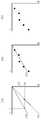
도 5(a)는 복수의 전류값(I)에 대한 자기장 측정값(B)을 각각 가로축과 세로축으로 나타낸 것이다. 가로축을 복수의 온도로 할 수도 있으며, 여러 개의 온도에 대하여 각각의 전류값을 측정할 수 있다.5 (a) shows the magnetic field measurement values B for the plurality of current values I on the horizontal and vertical axes, respectively. The horizontal axis may be a plurality of temperatures, and each current value may be measured for a plurality of temperatures.
도 5(b)는 도 5(a)에서 측정된 값들을 일차 선형 회귀 모형을 사용하여g(i)를 추출한 것이다.FIG. 5 (b) showsg (i) extracted from the values measured in FIG. 5 (a) using a linear linear regression model.
도 5(c)는 원래 정의되어 있던, 또는 미리 기준값으로 세팅되어 있던 기준 모형f(i)를, 추출된g(i)와 함께 도시한 그래프이다.FIG. 5C is a graph showing the reference modelf (i) originally defined or previously set to a reference value together with the extractedg (i) .
도 5(c)를 참조하면, 특정 전류값i에서f(i)와g(i)가 차이를 보이며, 원래 정의되어 있던f(i) 의 자기장을 형성하려면,i'의 전류를 공급 해야함을 알 수 있다.Referring to FIG. 5 (c),f (i) andg (i) are different at a specific current valuei , and in order to form a magnetic field off (i) which was originally defined, it is necessary to supplyi ' current. Able to know.
이를 수학식으로 나타내어 보면, 자기장은 전류에 비례하여 형성되므로, 원래 조향부(40)와 미리 정의되어 있던 전류대 자기장 함수f(i)를 수학식 1과 같이 나타낼 수 있다.As shown in the equation, since the magnetic field is formed in proportion to the current, the steering

일차 선형 회귀 모형으로 추출된g(i)는 수학식 2와 같이 나타낼 수 있다.G (i) extracted by the linear linear regression model may be represented by

따라서, 도 5(c)의I대i'의 관계는 수학식 3과 같이 나타낼 수 있다.Accordingly, the relationship ofI toi ' in FIG. 5C may be expressed as in Equation 3 below.

따라서, 도 5의 실시예에 의하면i'는 (

자기장의 보정 방법은 상술한 실시예에 한정되는 것은 아니며, 다양한 회귀 모형을 사용할 수 있고, 또한, 전류 제어가 주로 이루어지는 관심 전류 구간에서만 회귀 모형을 사용할 수도 있다.The correction method of the magnetic field is not limited to the above-described embodiment, and various regression models may be used, and the regression model may be used only in the current section of interest in which current control is mainly performed.
도 6은 본 발명의 또 다른 일 실시예에 따른 전자기 코일시스템 제어 방법에 대한 구체적인 일례를 나타내는 순서도(S50)이다.6 is a flowchart illustrating a specific example of a method for controlling an electromagnetic coil system according to another exemplary embodiment of the present invention.
도 6을 참조하면, S51 단계에서는, 체내 도입 장치(30) 사용 직전에 자기장측정부(12)가 복수의 전류값 및/또는 복수의 온도에서 각 코일(21, 22, … , 28)의 자기장을 측정할 수 있다.Referring to FIG. 6, in step S51, the magnetic
S53 단계에서는, 보정부(14)가 도 5의 실시예처럼 회귀 모형을 추출할 수 있다.In operation S53, the
S55 단계에서는, 도 5의 실시예처럼, 보정부(14)가 미리 정해져 있는 기준 모형과 S53 단계에서 추출된 회귀 모형에 기초하여 코일의 전류 보정값을 추출할 수 있다.In step S55, as in the embodiment of FIG. 5, the
S57 단계에서는, 체내 도입 장치(30) 사용 중에 전류측정부(18)가 도 4의 실시예처럼 각 코일(21, 22, … , 28)의 전류 변동값을 감지할 수 있다.In operation S57, the
S59 단계에서는, S55 단계에서 추출된 전류 보정값 및 감지된 S57 단계에서 감지된 전류 변동값에 기초하여 각 코일(21, 22, … , 28)의 전류를 제어할 수 있다.In step S59, the current of each
이상과 같이, 상술한 실시예들에 의하면, 본 발명에 따른 전자기 코일시스템 제어 장치(10) 및 방법은 코일시스템(20)을 각 코일(21, 22, … , 28)별로 전류에 기반하여 동작시키되, 체내 도입 장치(30)의 사용 전에는 코일시스템(20)의 동작 환경에 의한 왜곡된 자기장을 보정하여 전류 보정값을 추출하고, 체내 도입 장치(30)의 사용 중에는 각 코일(21, 22, … , 28)의 온도 상승에 따라 각 코일의 임피던스가 변하더라도 각 코일이 일정한 자기장을 형성하도록 제어함으로써, 코일시스템(20)의 자기장이 균질하게 유지되어 체내 도입 장치를 운전자가 의도한대로 정밀하게 조종할 수 있도록 하는 효과가 있다.As described above, according to the above-described embodiments, the electromagnetic coil
이상에서와 같이, 본 발명은 도면에 도시된 실시예를 참고로 설명되었으나 이는 예시적인 것에 불과하며, 본 기술 분야의 통상의 지식을 가진 자라면 이로부터 다양한 변형 및 균등한 다른 실시예가 가능하다는 점을 이해할 것이다. 따라서, 본 발명의 진정한 기술적 보호 범위는 첨부된 특허청구범위의 기술적 사상에 의하여 정해져야 할 것이다.As described above, the present invention has been described with reference to the embodiments shown in the drawings, but this is merely exemplary, and those skilled in the art may various modifications and equivalent other embodiments from this. Will understand. Therefore, the true technical protection scope of the present invention will be defined by the technical spirit of the appended claims.
10: 코일시스템 제어 장치
12: 자기장측정부
14: 보정부
16: 전류제어부
18: 전류측정부
20: 코일시스템
21, 22, …, 28: 코일
30: 체내 도입 장치
35: 자기 센서
40: 조향부10: coil system controller
12: magnetic field measuring unit
14: correction unit
16: current control unit
18: current measuring unit
20: coil system
21, 22,... , 28: coil
30: body introduction device
35: magnetic sensor
40: steering
Claims (13)
Translated fromKorean상기 코일시스템의 각 코일의 자기장을 측정하는 자기장측정부;
상기 각 코일의 측정된 자기장에 기초하여 상기 각 코일의 전류 보정값을 추출하는 보정부; 및
상기 각 코일의 임피던스가 변하더라도 상기 각 코일이 균질한 자기장을 형성하도록 상기 전류 보정값에 기초하여 상기 각 코일의 전류를 제어하는 전류제어부;
를 포함하고,
상기 보정부는,
상기 각 코일의 측정된 자기장을 보정하여 회귀(regression) 모형을 추출하고, 상기 각 코일의 미리 저장되어 있는 기준 모형 및 상기 각 코일의 추출된 회귀 모형에 기초하여 상기 전류 보정값을 추출하는 것을 특징으로 하는, 코일시스템 제어 장치.
A device for controlling a coil system that controls the body introduction device by electromagnetic induction,
A magnetic field measuring unit measuring a magnetic field of each coil of the coil system;
A correction unit extracting a current correction value of each coil based on the measured magnetic field of each coil; And
A current control unit controlling the current of each coil based on the current correction value so that each coil forms a homogeneous magnetic field even if the impedance of the coil changes;
Including,
The correction unit,
Extracting a regression model by correcting the measured magnetic field of each coil, and extracting the current correction value based on a pre-stored reference model of each coil and an extracted regression model of each coil. Coil system control apparatus.
상기 측정된 자기장은 상기 각 코일로부터 상기 도입 장치의 위치로 예상되는 지점에서 측정된 값인 것을 특징으로 하는, 코일시스템 제어 장치.
The method of claim 1,
And the measured magnetic field is a value measured at a point expected to be the position of the introduction device from each coil.
상기 자기장측정부는 복수의 전류값 또는 복수의 온도에서 자기장을 측정하는 것을 특징으로 하는, 코일시스템 제어 장치.
The method of claim 1,
The magnetic field measuring unit measures a magnetic field at a plurality of current values or a plurality of temperatures, coil system control device.
상기 전류제어부는 상기 각 코일의 실시간 온도 변화에 기초하여 상기 전류 보정값을 선택하는 것을 특징으로 하는, 코일시스템 제어 장치.
The method of claim 1,
And the current control unit selects the current correction value based on a real-time temperature change of each coil.
상기 각 코일의 전류 변동값을 감지하는 전류측정부를 더 포함하되,
상기 전류제어부는 상기 감지된 전류 변동값에 기초하여 상기 각 코일의 전류를 제어하는 것을 특징으로 하는, 코일시스템 제어 장치.
The method of claim 1,
Further comprising a current measuring unit for detecting a current change value of each coil,
And the current control unit controls the current of each coil based on the sensed current variation value.
상기 자기장의 측정은 상기 도입 장치를 사용하기 전에 수행하는 것을 특징으로 하는, 코일시스템 제어 장치.
The method of claim 1,
Coil system control device, characterized in that the measurement of the magnetic field is carried out before using the introduction device.
상기 전류 변동값의 감지는 상기 도입 장치를 사용하는 중에 수행하는 것을 특징으로 하는, 코일시스템 제어 장치.
The method of claim 7, wherein
And detecting the current fluctuation value while using the introduction device.
상기 코일시스템의 각 코일의 자기장을 측정하는 단계;
상기 각 코일의 측정된 자기장에 기초하여 상기 각 코일의 전류 보정값을 추출하는 단계;
상기 각 코일의 전류 변동값을 감지하는 단계; 및
상기 각 코일의 임피던스가 변하더라도 상기 각 코일이 균질한 자기장을 형성하도록 상기 전류 보정값 및 상기 감지된 전류 변동값에 기초하여 상기 각 코일의 전류를 제어하는 단계;
를 포함하고,
상기 전류 보정값을 추출하는 단계는,
상기 각 코일의 측정된 자기장을 보정하여 회귀 모형을 추출하는 단계; 및
상기 각 코일의 미리 저장되어 있는 기준 모형 및 상기 각 코일의 추출된 회귀 모형에 기초하여 상기 전류 보정값을 추출하는 단계;
를 포함하는 것을 특징으로 하는, 코일시스템 제어 방법.
As a method of controlling a coil system for controlling the body introduction device by electromagnetic induction,
Measuring a magnetic field of each coil of the coil system;
Extracting a current correction value of each coil based on the measured magnetic field of each coil;
Detecting a current variation value of each coil; And
Controlling the current of each coil based on the current correction value and the sensed current variation value such that each coil forms a homogeneous magnetic field even if the impedance of the coil changes;
Including,
Extracting the current correction value,
Extracting a regression model by correcting the measured magnetic field of each coil; And
Extracting the current correction value based on a pre-stored reference model of each coil and the extracted regression model of each coil;
Coil system control method comprising a.
상기 전류를 제어하는 단계는,
상기 각 코일의 온도 변화에 기초하여 상기 전류 보정값을 선택하는 단계를 포함하는 것을 특징으로 하는, 코일시스템 제어 방법.
The method of claim 10,
Controlling the current,
Selecting the current correction value based on a change in temperature of each coil.
Priority Applications (2)
| Application Number | Priority Date | Filing Date | Title |
|---|---|---|---|
| KR1020170092668AKR102061263B1 (en) | 2017-07-21 | 2017-07-21 | System and method for controlling an electromagnetic coil system |
| PCT/KR2018/008269WO2019017745A1 (en) | 2017-07-21 | 2018-07-23 | Device and method for controlling electromagnetic coil system |
Applications Claiming Priority (1)
| Application Number | Priority Date | Filing Date | Title |
|---|---|---|---|
| KR1020170092668AKR102061263B1 (en) | 2017-07-21 | 2017-07-21 | System and method for controlling an electromagnetic coil system |
Publications (2)
| Publication Number | Publication Date |
|---|---|
| KR20190010799A KR20190010799A (en) | 2019-01-31 |
| KR102061263B1true KR102061263B1 (en) | 2020-01-02 |
Family
ID=65016500
Family Applications (1)
| Application Number | Title | Priority Date | Filing Date |
|---|---|---|---|
| KR1020170092668AActiveKR102061263B1 (en) | 2017-07-21 | 2017-07-21 | System and method for controlling an electromagnetic coil system |
Country Status (2)
| Country | Link |
|---|---|
| KR (1) | KR102061263B1 (en) |
| WO (1) | WO2019017745A1 (en) |
Families Citing this family (1)
| Publication number | Priority date | Publication date | Assignee | Title |
|---|---|---|---|---|
| KR102601095B1 (en)* | 2021-11-05 | 2023-11-13 | 서울대학교산학협력단 | Magnetic field synthesis controller using minimum maximum norm current solution |
Citations (2)
| Publication number | Priority date | Publication date | Assignee | Title |
|---|---|---|---|---|
| JP2011500239A (en)* | 2007-10-30 | 2011-01-06 | シーメンス アクチエンゲゼルシヤフト | Method and endoscope system for guiding a capsule endoscope |
| JP2015526111A (en) | 2012-05-22 | 2015-09-10 | コビディエン エルピー | Treatment planning system |
Family Cites Families (5)
| Publication number | Priority date | Publication date | Assignee | Title |
|---|---|---|---|---|
| JP4709594B2 (en)* | 2004-08-03 | 2011-06-22 | オリンパス株式会社 | Magnetic guidance medical system |
| US7536218B2 (en)* | 2005-07-15 | 2009-05-19 | Biosense Webster, Inc. | Hybrid magnetic-based and impedance-based position sensing |
| DE102008004871B4 (en) | 2008-01-17 | 2013-05-16 | Siemens Aktiengesellschaft | Coil arrangement for guiding a magnetic element in a working space |
| KR101410214B1 (en)* | 2012-11-23 | 2014-06-20 | 전남대학교산학협력단 | Capsule endoscope actuation control system, and a capsule endoscope system having the same |
| KR101489593B1 (en)* | 2013-10-10 | 2015-02-06 | 재단법인대구경북과학기술원 | Method for controlling micro robot using coil system and method thereof |
- 2017
- 2017-07-21KRKR1020170092668Apatent/KR102061263B1/enactiveActive
- 2018
- 2018-07-23WOPCT/KR2018/008269patent/WO2019017745A1/ennot_activeCeased
Patent Citations (2)
| Publication number | Priority date | Publication date | Assignee | Title |
|---|---|---|---|---|
| JP2011500239A (en)* | 2007-10-30 | 2011-01-06 | シーメンス アクチエンゲゼルシヤフト | Method and endoscope system for guiding a capsule endoscope |
| JP2015526111A (en) | 2012-05-22 | 2015-09-10 | コビディエン エルピー | Treatment planning system |
Also Published As
| Publication number | Publication date |
|---|---|
| WO2019017745A1 (en) | 2019-01-24 |
| KR20190010799A (en) | 2019-01-31 |
Similar Documents
| Publication | Publication Date | Title |
|---|---|---|
| JP4504340B2 (en) | Method and apparatus for regulating body temperature in a non-contact manner | |
| JP6037964B2 (en) | Manipulator system | |
| US20150015254A1 (en) | Control of SAR Values in MR Imaging | |
| CN110575118B (en) | Capsule endoscope control system and electronic device | |
| US9125619B2 (en) | Radiographic examination apparatus and method for the same | |
| CA2591016A1 (en) | Model-based correction of position measurements | |
| US9846218B2 (en) | Calbration of a sensor assembly for use in medical position/orientation tracking | |
| KR102061263B1 (en) | System and method for controlling an electromagnetic coil system | |
| US20150297070A1 (en) | Endoscope fogging prevention system and endoscope fogging prevention method | |
| US8411138B2 (en) | Camera head separated type camera device | |
| KR102422480B1 (en) | Methods and devices for eye testing | |
| JP6265815B2 (en) | Electronic endoscope system | |
| EP1813183A1 (en) | Endoscope profile detector | |
| US11369252B2 (en) | Endoscope system, control device, control method, and computer-readable recording medium | |
| US9962065B2 (en) | Optical scanning observation system with drive voltage correction | |
| US9974432B2 (en) | Scanning endoscope apparatus with drive signal correction | |
| JP4790347B2 (en) | Bending part adjusting device for endoscope apparatus | |
| CN115436708A (en) | Measuring system for measuring the resistance to be measured | |
| KR101355174B1 (en) | Calibrating system of OCT probe optical traictory and the method | |
| CN112075933A (en) | System and method for station movement control | |
| JP2012075516A (en) | Endoscope system and calibration method of endoscope | |
| KR102043339B1 (en) | Lesion localization detecting apparatus and method for laparoscopic surgery | |
| KR100834542B1 (en) | Vein measuring device | |
| CN116236268A (en) | Spinal orthopedic device and control method for spinal orthopedic device | |
| KR20130136826A (en) | Apparatus and method for adjusting location of meg sensor and user head using image and distance information |
Legal Events
| Date | Code | Title | Description |
|---|---|---|---|
| A201 | Request for examination | ||
| PA0109 | Patent application | Patent event code:PA01091R01D Comment text:Patent Application Patent event date:20170721 | |
| PA0201 | Request for examination | ||
| E902 | Notification of reason for refusal | ||
| PE0902 | Notice of grounds for rejection | Comment text:Notification of reason for refusal Patent event date:20181220 Patent event code:PE09021S01D | |
| PG1501 | Laying open of application | ||
| AMND | Amendment | ||
| E601 | Decision to refuse application | ||
| PE0601 | Decision on rejection of patent | Patent event date:20190724 Comment text:Decision to Refuse Application Patent event code:PE06012S01D Patent event date:20181220 Comment text:Notification of reason for refusal Patent event code:PE06011S01I | |
| AMND | Amendment | ||
| PX0901 | Re-examination | Patent event code:PX09011S01I Patent event date:20190724 Comment text:Decision to Refuse Application Patent event code:PX09012R01I Patent event date:20190220 Comment text:Amendment to Specification, etc. | |
| PX0701 | Decision of registration after re-examination | Patent event date:20190924 Comment text:Decision to Grant Registration Patent event code:PX07013S01D Patent event date:20190822 Comment text:Amendment to Specification, etc. Patent event code:PX07012R01I Patent event date:20190724 Comment text:Decision to Refuse Application Patent event code:PX07011S01I Patent event date:20190220 Comment text:Amendment to Specification, etc. Patent event code:PX07012R01I | |
| X701 | Decision to grant (after re-examination) | ||
| GRNT | Written decision to grant | ||
| PR0701 | Registration of establishment | Comment text:Registration of Establishment Patent event date:20191224 Patent event code:PR07011E01D | |
| PR1002 | Payment of registration fee | Payment date:20191226 End annual number:3 Start annual number:1 | |
| PG1601 | Publication of registration | ||
| PR1001 | Payment of annual fee | Payment date:20220923 Start annual number:4 End annual number:4 |