KR102060390B1 - System for establishing virtual constraint boundaries - Google Patents
System for establishing virtual constraint boundariesDownload PDFInfo
- Publication number
- KR102060390B1 KR102060390B1KR1020157019252AKR20157019252AKR102060390B1KR 102060390 B1KR102060390 B1KR 102060390B1KR 1020157019252 AKR1020157019252 AKR 1020157019252AKR 20157019252 AKR20157019252 AKR 20157019252AKR 102060390 B1KR102060390 B1KR 102060390B1
- Authority
- KR
- South Korea
- Prior art keywords
- virtual
- boundary
- tracking
- instrument
- boundaries
- Prior art date
- Legal status (The legal status is an assumption and is not a legal conclusion. Google has not performed a legal analysis and makes no representation as to the accuracy of the status listed.)
- Active
Links
Images


Classifications
- A—HUMAN NECESSITIES
- A61—MEDICAL OR VETERINARY SCIENCE; HYGIENE
- A61B—DIAGNOSIS; SURGERY; IDENTIFICATION
- A61B34/00—Computer-aided surgery; Manipulators or robots specially adapted for use in surgery
- A61B34/20—Surgical navigation systems; Devices for tracking or guiding surgical instruments, e.g. for frameless stereotaxis
- A—HUMAN NECESSITIES
- A61—MEDICAL OR VETERINARY SCIENCE; HYGIENE
- A61B—DIAGNOSIS; SURGERY; IDENTIFICATION
- A61B17/00—Surgical instruments, devices or methods
- A61B17/02—Surgical instruments, devices or methods for holding wounds open, e.g. retractors; Tractors
- A—HUMAN NECESSITIES
- A61—MEDICAL OR VETERINARY SCIENCE; HYGIENE
- A61B—DIAGNOSIS; SURGERY; IDENTIFICATION
- A61B17/00—Surgical instruments, devices or methods
- A61B17/16—Instruments for performing osteoclasis; Drills or chisels for bones; Trepans
- A—HUMAN NECESSITIES
- A61—MEDICAL OR VETERINARY SCIENCE; HYGIENE
- A61B—DIAGNOSIS; SURGERY; IDENTIFICATION
- A61B17/00—Surgical instruments, devices or methods
- A61B17/56—Surgical instruments or methods for treatment of bones or joints; Devices specially adapted therefor
- A—HUMAN NECESSITIES
- A61—MEDICAL OR VETERINARY SCIENCE; HYGIENE
- A61B—DIAGNOSIS; SURGERY; IDENTIFICATION
- A61B34/00—Computer-aided surgery; Manipulators or robots specially adapted for use in surgery
- A61B34/30—Surgical robots
- A—HUMAN NECESSITIES
- A61—MEDICAL OR VETERINARY SCIENCE; HYGIENE
- A61B—DIAGNOSIS; SURGERY; IDENTIFICATION
- A61B34/00—Computer-aided surgery; Manipulators or robots specially adapted for use in surgery
- A61B34/30—Surgical robots
- A61B34/32—Surgical robots operating autonomously
- A—HUMAN NECESSITIES
- A61—MEDICAL OR VETERINARY SCIENCE; HYGIENE
- A61B—DIAGNOSIS; SURGERY; IDENTIFICATION
- A61B90/00—Instruments, implements or accessories specially adapted for surgery or diagnosis and not covered by any of the groups A61B1/00 - A61B50/00, e.g. for luxation treatment or for protecting wound edges
- A61B90/03—Automatic limiting or abutting means, e.g. for safety
- A—HUMAN NECESSITIES
- A61—MEDICAL OR VETERINARY SCIENCE; HYGIENE
- A61B—DIAGNOSIS; SURGERY; IDENTIFICATION
- A61B17/00—Surgical instruments, devices or methods
- A61B2017/00681—Aspects not otherwise provided for
- A61B2017/00734—Aspects not otherwise provided for battery operated
- A—HUMAN NECESSITIES
- A61—MEDICAL OR VETERINARY SCIENCE; HYGIENE
- A61B—DIAGNOSIS; SURGERY; IDENTIFICATION
- A61B34/00—Computer-aided surgery; Manipulators or robots specially adapted for use in surgery
- A61B34/10—Computer-aided planning, simulation or modelling of surgical operations
- A61B2034/101—Computer-aided simulation of surgical operations
- A61B2034/102—Modelling of surgical devices, implants or prosthesis
- A—HUMAN NECESSITIES
- A61—MEDICAL OR VETERINARY SCIENCE; HYGIENE
- A61B—DIAGNOSIS; SURGERY; IDENTIFICATION
- A61B34/00—Computer-aided surgery; Manipulators or robots specially adapted for use in surgery
- A61B34/10—Computer-aided planning, simulation or modelling of surgical operations
- A61B2034/101—Computer-aided simulation of surgical operations
- A61B2034/105—Modelling of the patient, e.g. for ligaments or bones
- A—HUMAN NECESSITIES
- A61—MEDICAL OR VETERINARY SCIENCE; HYGIENE
- A61B—DIAGNOSIS; SURGERY; IDENTIFICATION
- A61B34/00—Computer-aided surgery; Manipulators or robots specially adapted for use in surgery
- A61B34/20—Surgical navigation systems; Devices for tracking or guiding surgical instruments, e.g. for frameless stereotaxis
- A61B2034/2046—Tracking techniques
- A61B2034/2048—Tracking techniques using an accelerometer or inertia sensor
- A—HUMAN NECESSITIES
- A61—MEDICAL OR VETERINARY SCIENCE; HYGIENE
- A61B—DIAGNOSIS; SURGERY; IDENTIFICATION
- A61B34/00—Computer-aided surgery; Manipulators or robots specially adapted for use in surgery
- A61B34/20—Surgical navigation systems; Devices for tracking or guiding surgical instruments, e.g. for frameless stereotaxis
- A61B2034/2046—Tracking techniques
- A61B2034/2055—Optical tracking systems
- A—HUMAN NECESSITIES
- A61—MEDICAL OR VETERINARY SCIENCE; HYGIENE
- A61B—DIAGNOSIS; SURGERY; IDENTIFICATION
- A61B34/00—Computer-aided surgery; Manipulators or robots specially adapted for use in surgery
- A61B34/20—Surgical navigation systems; Devices for tracking or guiding surgical instruments, e.g. for frameless stereotaxis
- A61B2034/2046—Tracking techniques
- A61B2034/2061—Tracking techniques using shape-sensors, e.g. fiber shape sensors with Bragg gratings
- A—HUMAN NECESSITIES
- A61—MEDICAL OR VETERINARY SCIENCE; HYGIENE
- A61B—DIAGNOSIS; SURGERY; IDENTIFICATION
- A61B34/00—Computer-aided surgery; Manipulators or robots specially adapted for use in surgery
- A61B34/20—Surgical navigation systems; Devices for tracking or guiding surgical instruments, e.g. for frameless stereotaxis
- A61B2034/2046—Tracking techniques
- A61B2034/2065—Tracking using image or pattern recognition
- A—HUMAN NECESSITIES
- A61—MEDICAL OR VETERINARY SCIENCE; HYGIENE
- A61B—DIAGNOSIS; SURGERY; IDENTIFICATION
- A61B34/00—Computer-aided surgery; Manipulators or robots specially adapted for use in surgery
- A61B34/20—Surgical navigation systems; Devices for tracking or guiding surgical instruments, e.g. for frameless stereotaxis
- A61B2034/2068—Surgical navigation systems; Devices for tracking or guiding surgical instruments, e.g. for frameless stereotaxis using pointers, e.g. pointers having reference marks for determining coordinates of body points
- A—HUMAN NECESSITIES
- A61—MEDICAL OR VETERINARY SCIENCE; HYGIENE
- A61B—DIAGNOSIS; SURGERY; IDENTIFICATION
- A61B90/00—Instruments, implements or accessories specially adapted for surgery or diagnosis and not covered by any of the groups A61B1/00 - A61B50/00, e.g. for luxation treatment or for protecting wound edges
- A61B90/39—Markers, e.g. radio-opaque or breast lesions markers
- A61B2090/3937—Visible markers
- A61B2090/3945—Active visible markers, e.g. light emitting diodes
- A—HUMAN NECESSITIES
- A61—MEDICAL OR VETERINARY SCIENCE; HYGIENE
- A61B—DIAGNOSIS; SURGERY; IDENTIFICATION
- A61B90/00—Instruments, implements or accessories specially adapted for surgery or diagnosis and not covered by any of the groups A61B1/00 - A61B50/00, e.g. for luxation treatment or for protecting wound edges
- A61B90/39—Markers, e.g. radio-opaque or breast lesions markers
- A61B2090/3983—Reference marker arrangements for use with image guided surgery
- Y—GENERAL TAGGING OF NEW TECHNOLOGICAL DEVELOPMENTS; GENERAL TAGGING OF CROSS-SECTIONAL TECHNOLOGIES SPANNING OVER SEVERAL SECTIONS OF THE IPC; TECHNICAL SUBJECTS COVERED BY FORMER USPC CROSS-REFERENCE ART COLLECTIONS [XRACs] AND DIGESTS
- Y10—TECHNICAL SUBJECTS COVERED BY FORMER USPC
- Y10S—TECHNICAL SUBJECTS COVERED BY FORMER USPC CROSS-REFERENCE ART COLLECTIONS [XRACs] AND DIGESTS
- Y10S901/00—Robots
- Y10S901/02—Arm motion controller
- Y10S901/09—Closed loop, sensor feedback controls arm movement
- Y—GENERAL TAGGING OF NEW TECHNOLOGICAL DEVELOPMENTS; GENERAL TAGGING OF CROSS-SECTIONAL TECHNOLOGIES SPANNING OVER SEVERAL SECTIONS OF THE IPC; TECHNICAL SUBJECTS COVERED BY FORMER USPC CROSS-REFERENCE ART COLLECTIONS [XRACs] AND DIGESTS
- Y10—TECHNICAL SUBJECTS COVERED BY FORMER USPC
- Y10S—TECHNICAL SUBJECTS COVERED BY FORMER USPC CROSS-REFERENCE ART COLLECTIONS [XRACs] AND DIGESTS
- Y10S901/00—Robots
- Y10S901/46—Sensing device
- Y10S901/47—Optical
Landscapes
- Health & Medical Sciences (AREA)
- Surgery (AREA)
- Life Sciences & Earth Sciences (AREA)
- Engineering & Computer Science (AREA)
- Animal Behavior & Ethology (AREA)
- Veterinary Medicine (AREA)
- Biomedical Technology (AREA)
- Heart & Thoracic Surgery (AREA)
- Medical Informatics (AREA)
- Molecular Biology (AREA)
- Nuclear Medicine, Radiotherapy & Molecular Imaging (AREA)
- General Health & Medical Sciences (AREA)
- Public Health (AREA)
- Robotics (AREA)
- Oral & Maxillofacial Surgery (AREA)
- Pathology (AREA)
- Orthopedic Medicine & Surgery (AREA)
- Dentistry (AREA)
- Manipulator (AREA)
- Surgical Instruments (AREA)
- User Interface Of Digital Computer (AREA)
- Apparatus For Radiation Diagnosis (AREA)
Abstract
Translated fromKorean
Description
Translated fromKorean본 출원은 그 전체 내용이 본 명세서에 참고용으로 병합되는 2013년 3월 13일에 출원된 미국 가특허 출원 번호 61/780,148의 우선권 및 이익을 주장한다.This application claims the benefit and benefit of U.S. Provisional Patent Application No. 61 / 780,148, filed March 13, 2013, the entire contents of which are incorporated herein by reference.
본 발명은 일반적으로 가상 경계들을 확립하고 추적하기 위한 시스템들 및 방법들에 관한 것이다.The present invention generally relates to systems and methods for establishing and tracking virtual boundaries.
로봇형 수술에서, 가상 경계들은, 단부 이펙터(end effector)가 제약되는 영역들로부터 로봇 시스템의 단부 이펙터가 조종할 수 있는 영역들을 묘사하기 위해 컴퓨터 보조 설계 소프트웨어를 이용하여 생성된다. 예를 들어, 정형 외과 수술에서, 가상 절개 경계는 수술 이후에 남아있을 뼈의 섹션들로부터 수술 동안 단부 이펙터에 의해 제거될 뼈의 섹션들을 묘사하도록 생성될 수 있다.In robotic surgery, virtual boundaries are created using computer assisted design software to depict the areas that the end effector of the robotic system can manipulate from the areas where the end effector is constrained. For example, in orthopedic surgery, a virtual incision boundary may be created to depict sections of bone to be removed by an end effector during surgery from sections of bone that will remain after surgery.
항해 시스템은 가상 절개 경계에 대한 단부 이펙터의 위치 및/또는 방향을 결정하기 위해 가상 절개 경계에 대한 단부 이펙터의 이동을 추적한다. 로봇형 시스템은, 단부 이펙터가 가상 절개 경계를 지나 이동하지 않도록 단부 이펙터의 이동을 안내하기 위해 항해 시스템과 협력한다.The navigation system tracks the movement of the end effector relative to the virtual incision boundary to determine the position and / or direction of the end effector relative to the virtual incision boundary. The robotic system cooperates with the navigation system to guide the movement of the end effector such that the end effector does not move past the virtual incision boundary.
일반적으로, 가상 절개 경계들은 수술 이전에 생성된다. 가상 절개 경계들은 종종 환자의 뼈의 모델에 생성되고, 뼈에 대해 고정되어, 모델이 항해 시스템에 로딩될 때, 항해 시스템은 뼈의 이동을 추적함으로써 가상 절개 경계의 이동을 추적할 수 있다.In general, virtual incision boundaries are created prior to surgery. Virtual incision boundaries are often created in the model of the patient's bone and fixed relative to the bone so that when the model is loaded into the navigation system, the navigation system can track the movement of the virtual incision boundary by tracking the movement of the bone.
가상 경계들은 수술 동안 단부 이펙터에 의해 회피될 다른 해부학적 특징들을 한정할 수 있다. 그러한 특징들은 단부 이펙터와의 접촉으로부터 보호될 신경들 또는 다른 유형들의 조직을 포함한다. 가상 경계들은 또한 단부 이펙터를 치료되는 해부학적 구조로 향하게 하는 가상 경로들을 제공하는데 사용된다. 가상 경계들의 이들 예들은 종종 치료되는 해부학적 구조에 관계로 고정되어, 모든 경계들은 해부학적 구조가 이동함에 따라 함께 추적된다. 하지만, 수술실에서 몇몇 해부학적 특징들 또는 다른 대상들은 치료되는 해부학적 구조에 대해 이동할 수 있다. 예를 들어, 단부 이펙터에 대한 조직에서 개구부를 제공하는데 사용된 견인기들(retractors)은 치료되는 해부학적 구조에 대해 이동할 수 있다. 적절한 동적 가상 구속 경계를 이용하여 적절하게 추적되지 않으면, 단부 이펙터는 견인기들에 예기치 않게 충돌할 수 있다. 그 결과, 단부 이펙터는 손상을 입을 수 있거나 동작 불능(inoperative) 상태가 될 수 있고, 견인기는 그 위치로부터 퇴각될 수 있다.Virtual boundaries can define other anatomical features to be avoided by the end effector during surgery. Such features include nerves or other types of tissue to be protected from contact with the end effector. Virtual boundaries are also used to provide virtual paths that direct the end effector to the anatomical structure being treated. These examples of imaginary boundaries are often fixed relative to the anatomical structure being treated so that all the boundaries are tracked together as the anatomical structure moves. However, some anatomical features or other objects in the operating room may move relative to the anatomical structure being treated. For example, the retractors used to provide an opening in the tissue for the end effector may move relative to the anatomical structure being treated. If not properly tracked using the appropriate dynamic virtual constraint boundary, the end effector may unexpectedly hit the retractors. As a result, the end effector may be damaged or inoperable, and the retractor may be retracted from that position.
다른 일반적인 추적되지 않는 대상들은 또한 단부 이펙터에 의해 회피되어야 하는 단부 이펙터에 근접할 수 있고, 또한 치료되는 해부학적 구조에 대해 이동될 수 있다. 그러므로, 그러한 대상들을 위한 동적 가상 경계들을 생성하기 위한 시스템들 및 방법들이 종래 기술에 필요하다.
또한, 본 발명은 가상 경계들을 확립하고 추적하기 위한 시스템들 및 방법들을 제공함에 그 목적이 있다.Other common untracked subjects may also be close to the end effector to be avoided by the end effector and may also be moved relative to the anatomical structure being treated. Therefore, there is a need in the art for systems and methods for creating dynamic virtual boundaries for such objects.
It is also an object of the present invention to provide systems and methods for establishing and tracking virtual boundaries.
본 발명의 일실시예에서, 기구의 이동을 안내하기 위해 복수의 동적 가상 경계들을 이용하는 시스템이 제공된다. 시스템은 기구의 이동을 추적하기 위한 기구 추적 디바이스를 포함한다. 시스템은 또한 복수의 가상 경계들 중 제1 가상 경계의 이동을 추적하기 위한 제1 경계 추적 디바이스를 포함하고, 제1 가상 경계는 치료되는 해부학적 구조와 연관된다. 시스템은 복수의 가상 경계들 중 제2 가상 경계의 이동을 추적하기 위한 제2 경계 추적 디바이스를 더 포함하고, 제2 가상 경계는 기구에 의해 회피될 대상과 연관된다. 제어기는 제1 및 제2 가상 경계들에 대한 기구의 위치들을 포함하는 추적 디바이스들과 연관된 정보를 수신하도록 구성된다. 제어기는, 제1 및 제2 가상 경계들이 서로에 대해 이동될 때 제1 및 제2 가상 경계들 각각에 대한 기구의 이동을 안내하도록 구성된다.In one embodiment of the present invention, a system is provided that uses a plurality of dynamic virtual boundaries to guide movement of an instrument. The system includes an instrument tracking device for tracking the movement of the instrument. The system also includes a first boundary tracking device for tracking the movement of the first virtual boundary of the plurality of virtual boundaries, the first virtual boundary being associated with the anatomical structure being treated. The system further includes a second boundary tracking device for tracking the movement of the second virtual boundary of the plurality of virtual boundaries, the second virtual boundary associated with the object to be avoided by the instrument. The controller is configured to receive information associated with tracking devices that include positions of the instrument relative to the first and second virtual boundaries. The controller is configured to guide the movement of the instrument relative to each of the first and second virtual boundaries when the first and second virtual boundaries are moved relative to each other.
본 발명의 다른 실시예에서, 기구의 이동을 안내하기 위해 복수의 동적 가상 경계들을 이용하기 위한 방법이 제공된다. 방법은 치료될 해부학적 구조와 연관된 제1 가상 경계 및 기구의 이동을 추적하는 단계를 포함한다. 방법은 제1 가상 경계에 대해 제2 가상 경계의 이동을 추적하는 단계를 더 포함하고, 제2 가상 경계는 기구에 의해 회피될 대상과 연관된다. 기구의 이동은, 제1 및 제2 가상 경계들이 서로에 대해 이동할 때 제1 및 제2 가상 경계들 각각에 대해 안내된다.In another embodiment of the present invention, a method is provided for using a plurality of dynamic virtual boundaries to guide movement of an instrument. The method includes tracking the movement of the instrument and the first virtual boundary associated with the anatomical structure to be treated. The method further includes tracking the movement of the second virtual boundary relative to the first virtual boundary, wherein the second virtual boundary is associated with the object to be avoided by the instrument. Movement of the instrument is guided relative to each of the first and second virtual boundaries as the first and second virtual boundaries move relative to each other.
이들 실시예들의 하나의 장점은 기구를 추적하는 것 외에도, 해당 해부학적 구조에 대해 이동할 수 있는 대상들(다른 툴들 또는 해부학적 구조와 같은)을 동적으로 추적할 수 있는 능력이다. 제2 가상 경계는 해부학적 구조와 연관된 제1 가상 경계에 대한 이동을 위해 추적되는 가상 구속 경계 또는 다른 유형의 가상 경계일 수 있다.One advantage of these embodiments is the ability to dynamically track objects (such as other tools or anatomical structures) that can move relative to the anatomical structure in addition to tracking the instrument. The second virtual boundary may be a virtual constraint boundary or other type of virtual boundary that is tracked for movement relative to the first virtual boundary associated with the anatomical structure.
본 발명의 장점들은 이들이 첨부도들과 연계하여 고려될 때 다음의 상세한 설명을 참조하여 더 잘 이해될 때 쉽게 인식될 것이다.The advantages of the invention will be readily appreciated when they are better understood with reference to the following detailed description when considered in connection with the accompanying drawings.
본 발명은 가상 경계들을 확립하고 추적하기 위한 시스템들 및 방법들을 제공하는 효과가 있다.The present invention has the effect of providing systems and methods for establishing and tracking virtual boundaries.
도 1은 로봇형 시스템과 연계하여 사용되는 본 발명의 항해 시스템의 사시도.
도 2는 항해 시스템의 개략도.
도 3은 항해 시스템에 사용된 좌표 시스템들의 개략도.
도 4는 로봇형 시스템의 단부 이펙터에 의해 무릎 관절에 액세스하기 위한 조직 개구부의 사시도.
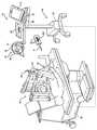
도 5는 조직 개구부를 유지하는데 사용되는 다리 홀더 및 견인기 조립체의 분해도.
도 6은 견인기의 상부 사시도.
도 7은 대안적인 견인기의 상부 사시도.
도 8은 조직 개구부의 이동을 추적하기 위해 조직 개구부에서의 단부 이펙터 및 유연한 형태의 감지 디바이스를 도시한 조직 개구부의 상부 사시도.
도 9는 조직 개구부의 이동을 추적하기 위해 조직 개구부에서의 단부 이펙터 및 기계 시각 시스템을 도시한 조직 개구부의 상부 사시도.1 is a perspective view of the navigation system of the present invention used in conjunction with a robotic system.
2 is a schematic representation of a navigation system.
3 is a schematic diagram of coordinate systems used in a navigation system.
4 is a perspective view of a tissue opening for accessing the knee joint by an end effector of the robotic system.
5 is an exploded view of the leg holder and retractor assembly used to maintain tissue openings.
6 is a top perspective view of the retractor.
7 is a top perspective view of an alternative retractor.
8 is a top perspective view of the tissue opening showing the end effector and flexible sensing device in the tissue opening to track movement of the tissue opening.
9 is a top perspective view of the tissue opening showing the end effector and machine vision system at the tissue opening to track movement of the tissue opening.
도 1을 참조하면, 수술용 항해 시스템(20)이 도시된다. 시스템(20)은 의료용 설비의 수술실과 같은 수술적 세팅(surgical setting)에 도시된다. 항해 시스템(20)은 수술실에서 다양한 대상들의 이동을 추적하도록 설정된다. 그러한 대상들은 예를 들어, 수술용 기구(22), 환자의 대퇴골(F), 및 환자의 경골(T)을 포함한다. 항해 시스템(20)은 그 상대적인 위치들 및 방향들을 의사에게 디스플레이하기 위해, 그리고 몇몇 경우들에서, 대퇴골(F) 및 경골(T)과 연관된 가상 절개 경계들에 대해 수술용 기구(22)의 이동을 제어하거나 구속하기 위해 이들 대상들을 추적한다.Referring to FIG. 1, a
수술용 항해 시스템(20)은 항해 컴퓨터(26)를 수용하는 컴퓨터 카트 조립체(24)를 포함한다. 항해 인터페이스는 항해 컴퓨터(26)와 동작가능하게 통신 상태에 있다. 항해 인터페이스는 살균장의 외부에 위치되도록 적응된 제1 디스플레이(28)와, 살균장 내부에 위치되도록 적응된 제2 디스플레이(29)를 포함한다. 디스플레이들(28, 29)은 컴퓨터 카트 조립체(24)에 조정가능하게 장착된다. 키보드 및 마우스와 같은 제1 및 제2 입력 디바이스들(30, 32)은 정보를 항해 컴퓨터(26)에 입력하는데 사용될 수 있거나, 그렇지 않으면 항해 컴퓨터(26)의 특정한 양상들을 선택/제어하는데 사용될 수 있다. 터치 스크린(미도시) 또는 음성-작용을 포함하는 다른 입력 디바이스들이 구상된다.
로컬라이저(localizer)(34)는 항해 컴퓨터(26)와 통신한다. 도시된 실시예에서, 로컬라이저(34)는 광학 로컬라이저이고, 카메라 유닛(36)(감지 디바이스의 일례)을 포함한다. 카메라 유닛(36)은 하나 이상의 광학 위치 센서들(40)을 수용하는 외부 케이스(casing)(38)를 갖는다. 몇몇 실시예들에서, 적어도 2개의 광학 센서들(40), 바람직하게 3개의 광학 센서들이 이용된다. 광학 센서들(40)은 3개의 개별적인 전하-결합 디바이스들(CCD)일 수 있다. 일실시예에서, 3개의 1차원 CCD가 이용된다. 다른 실시예들에서, 각각 개별적인 CCD, 또는 2개 이상의 CCD들을 갖는 개별적인 카메라 유닛들이 또한 수술실 주위에 배치될 수 있다는 것이 인식되어야 한다. CCD들은 적외선(IR) 신호를 검출한다.Localizer 34 is in communication with
카메라 유닛(36)은, 이상적으로 장애물들이 없는 아래에 논의되는 추적기들의 시야를 갖는 광학 센서들(40)을 위치시키기 위해 조정가능한 아암 상에 장착된다. 몇몇 실시예들에서, 카메라 유닛(36)은 회전 조인트 주위를 회전함으로써 적어도 하나의 자유도로 조정가능하다. 다른 실시예들에서, 카메라 유닛(36)은 약 2개 이상의 자유도로 조정가능하다.
카메라 유닛(36)은 광학 센서들(40)로부터 신호를 수신하기 위해 광학 센서들(40)과 통신하는 카메라 제어기(42)를 포함한다. 카메라 제어기(42)는 유선 또는 무선 연결부(미도시)를 통해 항해 컴퓨터(26)와 통신한다. 하나의 그러한 연결부는 IEEE 1394 인터페이스일 수 있고, 이것은 고속 통신 및 비동기 실시간 데이터 전달을 위한 직렬 버스 인터페이스 표준이다. 연결부는 또한 회사 특정 프로토콜을 이용할 수 있다. 다른 실시예들에서, 광학 센서들(40)은 항해 컴퓨터(26)와 직접 통신한다.The
위치 및 방향 신호 및/또는 데이터는 대상들을 추적하기 위해 항해 컴퓨터(26)에 전송된다. 컴퓨터 카트 조립체(24), 디스플레이(28), 및 카메라 유닛(36)은 본 명세서에 참고용으로 병합된 "수술 시스템(Surgery System)"이라는 명칭으로 2010년 5월 25일에 특허 허여된 Malackowski 등의 미국 특허 번호 7,725,162에 기재된 것들과 같을 수 있다.Position and direction signals and / or data are transmitted to the
항해 컴퓨터(26)는 개인용 컴퓨터 또는 랩탑 컴퓨터일 수 있다. 항해 컴퓨터(26)는 디스플레이(28), 중앙 처리 유닛(CPU) 및/또는 다른 프로세스들, 메모리(미도시), 및 저장부(미도시)를 갖는다. 항해 컴퓨터(26)는 아래에 기재되는 소프트웨어를 통해 로딩된다. 소프트웨어는 카메라 유닛(36)으로부터 수신된 신호를 추적되는 대상들의 위치 및 방향을 나타내는 데이터로 변환한다.The
항해 시스템(20)은 또한 본 명세서에서 추적기들로 언급되는 복수의 추적 디바이스들(44, 46, 48)을 포함한다. 예시된 실시예에서, 하나의 추적기(44)는 환자의 대퇴부(F)에 단단히 부착되고, 다른 추적기(46)는 환자의 경골(T)에 단단히 부착된다. 추적기들(44, 46)은 뼈의 섹션들에 단단히 부착된다. 추적기들(44, 46)은 본 명세서에 참고용으로 병합되는 미국 특허 번호 7,725,162에 도시된 방식으로 대퇴부(F) 및 경골(T)에 부착될 수 있다. 추적기들(44, 46)은 또한 본 명세서에 참고용으로 병합되는, "추적 디바이스들 및 항해 시스템들과, 그 이용 방법들(Tracking Devices and Navigation Systems and Methods for Use Thereof)"라는 명칭으로 2013년 1월 16일에 출원된 미국 가특허 출원 61/753,219에 도시된 것들과 같이 장착될 수 있다. 추가 실시예들에서, 추적기(미도시)는 슬개골의 위치 및 방향을 추적하기 위해 슬개골에 부착된다. 또 다른 실시예들에서, 추적기들(44, 46)은 해부학적 구조의 다른 조직 유형들 또는 부분들에 장착될 수 있다.The
기구 추적기(48)는 수술용 기구(22)에 단단히 부착된다. 기구 추적기(48)는 제조 동안 수술용 기구(22)에 일체화될 수 있거나, 수술 절차들을 준비할 때 수술용 기구(22)에 개별적으로 장착될 수 있다. 기구 추적기(48)로 인해 추적되는 수술용 기구(22)의 작업 단부(working end)는 회전 버(bur), 전기 절제 디바이스 등일 수 있다.
추적기들(44, 46, 48)은 내부 배터리를 통해 전력 공급된(powered) 배터리일 수 있거나, 카메라 유닛(36)과 같이 바람직하게 외부 전력을 수용하는 항해 컴퓨터(26)를 통해 전력을 수용하도록 리드들(leads)을 가질 수 있다.The
도시된 실시예에서, 수술용 기구(22)는 수술용 조절기(manipulator)에 부착된다. 그러한 장치(arrangement)는, 그 개시가 본 명세서에 참고용으로 병합되는, "다중 모드들로 수술용 기구를 제어할 수 있는 수술용 조절기(Surgical Manipulator Capable of Controlling a Surgical Instrument in Multiple Modes)"라는 명칭의 미국 특허 출원 13/958,070에 도시되어 있다.In the embodiment shown,
다른 실시예들에서, 수술용 기구(22)는 임의의 절개 가이드, 지그(jig)의 도움없이 사용자의 손으로만 수동으로 위치될 수 있거나, 조절기 또는 로봇과 같은 다른 구속 메커니즘에 의해 수동으로 위치될 수 있다. 그러한 수술용 기구는 본 명세서에 참고용으로 병합된, "하우징과, 하우징으로부터 연장하는 절개 액세서리, 및 하우징에 대해 절개 액세서리의 위치를 확립하는 엑추에이터들을 포함하는 기구(Sugical Instrument Including Housing, a Cutting Accessory that Extends from the Housing and Actuators that Establish the Position of the Cutting Accessory Relative to the Housing)"이라는 명칭으로 2012년 8월 31일에 출원된 미국 특허 출원 13/600,888에 기재되어 있다.In other embodiments,
로컬라이저(34)의 광학 센서들(40)은 추적기들(44, 46, 48)로부터 광 신호를 수신한다. 예시된 실시예에서, 추적기들(44, 46, 48)은 능동 추적기들이다. 이 실시예에서, 각 추적기(44, 46, 48)는 광 신호를 광학 센서들(40)에 전송하기 위한 적어도 3개의 능동 추적 요소들 또는 마커들을 갖는다. 능동 마커들은 예를 들어, 적외선 광과 같은 광을 투과하는 발광 다이오드 즉 LED(50)일 수 있다. 광학 센서들(40)은 바람직하게 100Hz 이상, 더 바람직하게 300Hz 이상, 가장 바람직하게 500Hz 이상의 샘플링 율을 갖는다. 몇몇 실시예들에서, 광학 센서들(40)은 8000Hz의 샘플링 율을 갖는다. 샘플링 율은, 광학 센서들(40)이 순차적으로 발사된 LED들(50)로부터 광 신호를 수신하는 비율이다. 몇몇 실시예들에서, LED들(50)로부터의 광 신호는 각 추적기(44, 46, 48)에 대해 상이한 비율로 발사된다.
도 2을 참조하면, 각 LED들(50)은 데이터를 항해 컴퓨터(26)로/로부터 전송/수신하는 연관된 추적기(44, 46, 48)의 하우징(미도시)에 위치된 추적기 제어기(62)에 연결된다. 일실시예에서, 추적기 제어기(62)는 항해 컴퓨터(26)와의 유선 연결부들을 통해 약 수 메가바이트/초로 데이터를 전송한다. 다른 실시예들에서, 무선 연결부가 사용될 수 있다. 이들 실시예들에서, 항해 컴퓨터(26)는 추적기 제어기(62)로부터 데이터를 수신하기 위해 트랜시버(미도시)를 갖는다.Referring to FIG. 2, each of the
다른 실시예들에서, 추적기(44, 46,48)는 카메라 유닛(36)으로부터 방출된 광을 반사하는 반사기들과 같은 수동 마커들(미도시)을 가질 수 있다. 반사된 광은 이 후 광학 센서들(40)에 의해 수신된다. 능동 및 수동 장치들이 종래 기술에 잘 알려져 있다.In other embodiments, the
몇몇 실시예들에서, 추적기들(44, 46, 48)은 또한 본 명세서에 참고용으로 병합된, "추적 디바이스들 및 항해 시스템들과, 그 이용 방법들(Tracking Devices and Navigation Systems and Methods for Use Thereof)"라는 명칭으로 2013년 1월 16일에 출원된 미국 가특허 출원 61/753,219에 도시된 추적기들과 같이 자이로스코프 센서(60) 및 가속도계(70)를 포함한다.In some embodiments,
항해 컴퓨터(26)는 항해 프로세서(52)를 포함한다. 항해 프로세서(52)가 항해 컴퓨터(26)의 동작을 제어하기 위해 하나 이상의 프로세서들을 포함할 수 있다는 것이 이해되어야 한다. 프로세서들은 임의의 유형의 마이크로프로세서 또는 다중-프로세서 시스템일 수 있다. 프로세서라는 용어는 본 발명의 범주를 단일 프로세서에 제한하도록 의도되지 않는다.The
카메라 유닛(36)은 추적기들(44, 46, 48)의 LED들(50)로부터 광학 신호를 수신하고, 로컬라이저(34)에 대해 추적기들(44, 46, 48)의 LED들(50)의 위치에 관련된 신호를 프로세서(52)로 출력한다. 수신된 광학(및 몇몇 실시예들에서 비-광학 신호)에 기초하여, 항해 프로세서(52)는 로컬라이저(34)에 대한 추적기들(44, 46, 48)의 상대적인 위치들 및 방향들을 표시하는 데이터를 생성한다.The
수술 절차의 시작 이전에, 추가 데이터는 항해 프로세서(52)에 로딩된다. 추적기들(44, 46, 48)의 위치 및 방향과 이전에 로딩된 데이터에 기초하여, 항해 프로세서(52)는 수술용 기구(22)의 작업 단부의 위치와, 작업 단부가 적용될 조직에 대한 수술용 기구(22)의 방향을 결정한다. 몇몇 실시예들에서, 항해 프로세서(52)는 이들 데이터를 조절기 제어기(54)에 송출한다. 조절기 제어기(54)는 이 후, 그 개시가 본 명세서에 참고용으로 병합되는, "반-자동 모드 또는 수동, 경계 구속 모드로 수술용 기구를 제어할 수 있는 수술용 조절기(Surgical Manipulator Capable of Controlling a Surgical Instrument in either a Semi-Autonomous Mode or a Manual, Boundary Constrained Mode,)"라는 명칭의 미국 가특허 출원 61/679,258에 기재된 바와 같이 로봇형 조절기(56)를 제어하기 위해 데이터를 이용할 수 있다.Prior to the start of the surgical procedure, additional data is loaded into the
항해 프로세서(52)는 또한 조직에 대한 수술용 기구 작업 단부의 상대적인 위치를 표시하는 이미지 신호를 생성한다. 이들 이미지 신호는 디스플레이들(28, 29)에 적용된다. 이들 신호에 기초하여 디스플레이들(28, 29)은, 의사 및 스태프가 수술 부위에 대한 수술용 기구 작업 단부의 상대적인 위치를 볼 수 있도록 하는 이미지들을 생성한다. 전술한 바와 같이, 디스플레이들(28, 29)은 명령들의 입력을 허용하는 터치 스크린 또는 다른 입력/출력 디바이스를 포함할 수 있다.The
도 3을 참조하면, 대상둘의 추적은 일반적으로 로컬라이저 좌표 시스템(LCLZ)을 참조하여 수행된다. 로컬라이저 좌표 시스템은 원점 및 방향(x-, y-, 및 z-축들의 세트)을 갖는다. 절차 동안, 하나의 목적은 로컬라이저 좌표 시스템(LCLZ)을 알려진 위치에 유지하는 것이다. 카메라 유닛(36)에 장착된 가속도계(미도시)는, 카메라 유닛(36)이 수술 요원에 의해 예기치 않게 부딪힐 때 발생할 수 있는 바와 같이, 로컬라이저 좌표 시스템(LCLZ)의 갑작스런 또는 돌발적인 이동을 추적하는데 사용될 수 있다.Referring to FIG. 3, tracking of two objects is generally performed with reference to a localizer coordinate system (LCLZ). The localizer coordinate system has an origin and a direction (set of x-, y-, and z-axes). During the procedure, one purpose is to keep the localizer coordinate system LCLZ in a known position. An accelerometer (not shown) mounted to the
각 추적기(44, 46, 48) 및 추적될 대상은 또한 로컬라이저 좌표 시스템(LCLZ)으로부터 분리된 자체 좌표 시스템을 갖는다. 자체 좌표 시스템들을 갖는 항해 시스템(20)의 구성요소들은 뼈 추적기들(44, 46) 및 기구 추적기(48)이다. 이들 좌표 시스템들은 각각 뼈 추적기 좌표 시스템들(BTRK1, BTRK2), 및 기구 추적기 좌표 시스템(TLTR)으로서 나타난다.Each
항해 시스템(20)은 뼈에 단단히 부착된 뼈 추적기들(44, 46)의 위치를 모니터링함으로써 환자의 대퇴부(F) 및 경골(T)의 위치들을 모니터링한다. 대퇴부 좌표 시스템은 FBONE이고, 경골 좌표 시스템은 TBONE인데, 이들은, 뼈 추적기들(44, 46)이 단단히 부착되는 뼈들의 좌표 시스템들이다.The
절차의 시작 이전에, 대퇴부(F) 및 경골(T)의(또는, 다른 실시예들에서 다른 조직들의) 사전-동작 이미지들이 생성된다. 이들 이미지들은 환자의 해부학적 구조의 MRI 스캔들, 방사선 스캔들 또는 컴퓨터 단층 촬영(CT) 스캔들에 기초할 수 있다. 이들 이미지들은 종래 기술에 잘 알려진 방법들을 이용하여 대퇴부 좌표 시스템(FBONE) 및 경골 좌표 시스템(TBONE)에 매핑(mapped)된다. 이들 이미지들은 대퇴부 좌표 시스템(FBONE) 및 경골 좌표 시스템(TBONE)에 고정된다. 사전-동작 이미지들에 대한 대안으로서, 치료를 위한 계획들은 운동학적 연구들, 뼈 트레이싱(tracing), 및 다른 방법들로부터 수술실(OR)에서 전개될 수 있다.Prior to the start of the procedure, pre-operative images of the femur F and tibia T (or of other tissues in other embodiments) are generated. These images may be based on MRI scans, radiography scans or computed tomography (CT) scans of the patient's anatomical structure. These images are mapped to the femoral coordinate system (FBONE) and the tibial coordinate system (TBONE) using methods well known in the art. These images are fixed to the femoral coordinate system FBONE and the tibial coordinate system TBONE. As an alternative to pre-motion images, plans for treatment can be developed in the operating room (OR) from kinematic studies, bone tracing, and other methods.
절차의 초기 단계 동안, 뼈 추적기들(44, 46)은 환자의 뼈들에 단단히 부착된다. 좌표 시스템들(FBONE 및 TBONE)의 포즈(위치 및 방향)는 각각 좌표 시스템들(BTRK1 및 BTRK2)에 매핑된다. 일실시예에서, 자체 추적기(PT)(도 2를 참조)를 갖는, 본 명세서에 참고용으로 병합되는 Malackowski 등의 미국 특허 번호 7,725,162에 개시된 것과 같은 포인터 기구(P)(도 1 및 도 2를 참조)는 각각 대퇴부 좌표 시스템(FBONE) 및 경골 좌표 시스템(TBONE)을 뼈 추적기 좌표 시스템들(BTRK1 및 BTRK2)에 등록하는데 사용될 수 있다. 뼈들과 뼈 추적기들(44, 46) 사이의 고정된 관계가 주어지면, 대퇴부 좌표 시스템(FBONE) 및 경골 좌표 시스템(TBONE)에서 대퇴부(F) 및 경골(T)의 위치들 및 방향들은 뼈 추적기 좌표 시스템들(BTRK1 및 BTRK2)로 변형될 수 있어서, 카메라 유닛(36)은 뼈 추적기들(44, 46)을 추적함으로써 대퇴부(F) 및 경골(T)을 추적할 수 있다. 이러한 포즈-기재 데이터는 조절기 제어기(54) 및 항해 프로세서(52) 모두와 일체형인 메모리에 저장된다.During the initial phase of the procedure,
수술용 기구(22)의 작업 단부(또한 에너지 적용기 말단 단부로 언급됨)는 자체 좌표 시스템(EAPP)을 갖는다. 좌표 시스템(EAPP)의 원점은 예를 들어, 수술용 절개 버의 질량 중심을 나타낼 수 있다. 좌표 시스템(EAPP)의 포즈는 절차가 시작하기 전에 기구 추적기 좌표 시스템(TLTR)의 포즈에 고정된다. 따라서, 서로에 대한 이들 좌표 시스템들(EAPP, TLTR)의 포즈들이 결정된다. 포즈-기재 데이터는 조절기 제어기(54) 및 항해 프로세서(52) 모두와 일체형인 메모리에 저장된다.The working end of surgical instrument 22 (also referred to as the energy applicator distal end) has its own coordinate system (EAPP). The origin of the coordinate system EAPP can represent, for example, the center of mass of the surgical incision bur. The pose of the coordinate system EAPP is fixed to the pose of the instrument tracker coordinate system TLTR before the procedure begins. Thus, the poses of these coordinate systems EAPP, TLTR relative to each other are determined. Pose-based data is stored in memory integrated with both
도 2를 참조하면, 국부화(localization) 엔진(100)은 항해 시스템(20)의 고려된 부분일 수 있는 소프트웨어 모듈이다. 국부화 엔진(100)의 구성요소들은 항해 프로세서(52) 상에서 실행된다. 본 발명의 몇몇 버전들에서, 국부화 엔진(100)은 조절기 제어기(54) 상에서 실행될 수 있다.Referring to FIG. 2, the
국부화 엔진(100)은 카메라 제어기(42)로부터 광학-기반의 신호를 입력으로서 수신하고, 몇몇 실시예들에서, 추적기 제어기(62)로부터 비-광학 기반의 신호를 수신한다. 이들 신호에 기초하여, 국부화 엔진(100)은 로컬라이저 좌표 시스템(LCLZ)에서의 뼈 추적기 좌표 시스템(BTRK1 및 BTRK2)의 포즈를 결정한다. 기구 추적기(48)를 위해 수신된 동일한 신호에 기초하여, 국부화 엔진(100)은 로컬라이저 좌표 시스템(LCLZ)에서의 기구 추적기 좌표 시스템(TLTR)의 포즈를 결정한다.
국부화 엔진(100)은 추적기들(44, 46, 48)의 포즈를 나타내는 신호를 좌표 변형기(102)로 송출한다. 좌표 변형기(102)는 항해 프로세서(52) 상에서 실행되는 항해 시스템 소프트웨어 모듈이다. 좌표 변형기(102)는 환자의 사전-동작 이미지들과 뼈 추적기들(44, 46) 사이의 관계를 한정하는 데이터를 참조한다. 좌표 변형기(102)는 또한 기구 추적기(48)에 대해 수술용 기구의 작업 단부의 포즈를 나타내는 데이터를 저장한다.The
절차 동안, 좌표 변형기(102)는 로컬라이저(34)에 대한 추적기들(44, 46, 48)의 상대적인 포즈들을 나타내는 데이터를 수신한다. 이들 데이터 및 이전에 로딩된 데이터에 기초하여, 좌표 변형기(102)는 로컬라이저 좌표 시스템(LCLZ)에 대한 좌표 시스템(EAPP), 및 뼈 좌표 시스템들(FBONE 및 TBONE) 모두의 상대 위치 및 방향을 나타내는 데이터를 생성한다.During the procedure, coordinate
그 결과, 좌표 변형기(102)는, 기구 작업 단부가 적용되는 조직(예를 들어, 뼈)에 대한 수술용 기구(22)의 작업 단부의 위치 및 방향을 나타내는 데이터를 생성한다. 이들 데이터를 나타내는 이미지 신호는 디스플레이들(28, 29)에 송출되어, 의사 및 스태프가 이 정보를 볼 수 있게 한다. 특정 실시예들에서, 이들 데이터를 나타내는 다른 신호는 조절기(56) 및 수술용 기구(22)의 대응하는 이동을 안내하기 위해 조절기 제어기(54)에 송출될 수 있다.As a result, coordinate
환자를 치료하기 위해 수술용 기구(22)를 이용하기 전에, 환자를 드레이핑(draping)하는 것과 치료를 위해 수술 부위를 준비하는 것과 같은 특정한 준비들이 필요하다. 예를 들어, 무릎 인공 관절 수술시, 수술 요원은 다리 홀더에서 해당 다리를 고정할 수 있고, 환자 및 기기를 드레이핑할 수 있다. 하나의 그러한 다리 홀더는 본 명세서에 참고용으로 병합된, 미국 특허 출원 공보 2013/0019883으로서 공개된 "다중-위치 림 홀더(Multi-position Limb Holder)"라는 명칭의 미국 특허 출원 13/554,010에 도시되어 있다.Before using
다른 준비들은 수술실에서 수술을 위해 필요한 대상들을 위치시키는 것을 포함한다. 이들 대상들 중 몇몇은, 수술 기구(22)가 조종될 영역들에 근접하게 사용된다. 이들 대상들은 다리 홀더들, 견인기들, 흡입/세정 툴들, 수술 요원 등을 포함할 수 있다. 수술 동안, 이들 대상들은 수술용 기구(22)에 의해 회피될 것이다. 수술 동안 이들 대상들의 회피를 용이하게 하기 위해, 이들 대상들 중 하나 이상에 대한 위치 정보는 직접적으로 또는 간접적으로 결정된다. 몇몇 실시예들에서, 대상들 중 하나 이상은 수술 동안 항해 시스템(20)에 의해 동적으로 추적된다.Other preparations include positioning the objects needed for surgery in the operating room. Some of these objects are used in close proximity to the areas where the
도 4를 참조하면, 일실시예에서, 위치 정보는 포인터 기구(P)를 이용하여 대상으로부터 간접적으로 얻어질 수 있고, 그 예는 본 명세서에 참고용으로 병합된 Malackowski 등의 미국 특허 번호 7,725,162에 개시되어 있다. 포인터(P)는 추적기들(44, 46, 48)과 동일한 방식으로 신호를 카메라 유닛(36)에 전송하는 LED들(50)을 갖는 자체 추적기(PT)를 갖는다. 포인터(P)의 팁의 위치는 포인터(P) 상의 LED들(50)에 상대적으로 알려져 있고, 트랜시버들을 통해 나중에 카메라 유닛(36)에 전송하기 위해 전자 포맷으로 포인터(P)에 저장된다. 대안적으로, 팁에 대한 위치 정보는 항해 컴퓨터(26)에 저장되거나, 해당 분야에서 알려진 장소에서 교정된다. 어느 경우에서도, 팁 위치가 알려져 있기 때문에, 포인터(P)는 수술용 기구(22)에 의해 회피될 대상들의 위치들을 결정하는데 사용될 수 있다.Referring to FIG. 4, in one embodiment, location information may be obtained indirectly from a subject using a pointer mechanism P, an example of which is described in US Pat. No. 7,725,162 to Malackowski et al., Which is incorporated herein by reference. Is disclosed. The pointer P has its own tracker PT with
일단 팁이 대상의 특정 표면들을 터치하면, 포인터(P) 상의 트리거 또는 스위치(미도시)는 사용자에 의해 작동되거나, 대안적으로, 팁은 표면과 접촉할 때 자동으로 감지하는 센서를 포함할 수 있다. 대응하는 신호는 포인터 추적기(PT) 상의 LED들(50)로부터 신호를 판독하기 위해 카메라 유닛(36) 상의 트랜시버로 송신되어, 팁의 위치는 교정될 수 있고, 이것은 대상의 표면 상의 포인트에 상관된다. 표면 상의 더 많은 포인트들이 팁에 의해 터치되고 그 위치들이 항해 시스템(20)에 의해 교정되기 때문에, 대상의 모델들은 로컬라이저 좌표 시스템(LCLZ)에서 대상의 위치 및 방향을 한정하도록 생성될 수 있다. 그러한 모델들은 종래의 표면 매핑 툴들 등을 이용하여 생성될 수 있다.Once the tip touches certain surfaces of the subject, the trigger or switch (not shown) on the pointer P may be actuated by the user, or alternatively, the tip may include a sensor that automatically senses when it contacts the surface. have. The corresponding signal is sent to the transceiver on the
생성된 모델들은 수술용 기구(22)의 이동을 안내하기 위해 가상 구속 경계들로서 이용된다. 모델들은 대상들의 장소들을 보기 위해 디스플레이들(28, 29) 상에서 디스플레이될 수 있고, 및/또는 모델들에 관련된 정보는 대상이 수술용 기구(22)에 의해 접촉되는 것을 방지하기 위해 이들 가상 구속 경계들에 관한 조절기(56) 및 수술용 기구(22)의 대응하는 이동을 안내하기 위해 조절기 제어기(54)에 송출될 수 있다.The generated models are used as virtual restraint boundaries to guide the movement of
대상이 수술 동안 고정적일 때, 위치 및/또는 방향을 결정하는 상기 방법은 가상 구속 경계를 제공하는데 적합하거나, 추적될 대상이 고정적이지 않으면, 다른 추적된 대상에 관한 고정된 장소에서 적합하다. 하지만, 대상이 일반적으로 수술 동안 이동하면, 대상의 연속적인 추적을 가능하게 하기 위해 추가 조치들이 필요하다. 몇몇 실시예들에서, 장착 가능 추적기들(110)은 대상들에 장착될 수 있다. 이들 추적기들(110)은 대상들에 대해 포괄적일 수 있어서, 대상들에 교정되지 않을 수 있다. 이 경우에, 추적기들(110)은 먼저 대상들에 부착된다.When the subject is stationary during surgery, the method of determining position and / or orientation is suitable for providing a virtual constraint boundary, or in a fixed place relative to another tracked subject if the subject to be tracked is not stationary. However, if the subject generally moves during surgery, additional measures are needed to enable continuous tracking of the subject. In some embodiments,
하나의 그러한 대상은 도 4에 도시된 견인기 조립체들(104)과 같은 견인기일 수 있다. 추적기들(110)은 본 명세서에서 참고용으로 병합된 Malackowski 등의 미국 특허 7,725,162에 도시된 것들과 같이 견인기 조립체들(104) 상에 위치된 추적기 연결기에 의해 견인기 조립체들(104)에 부착될 수 있거나, 추적기들(110)은 추적기들(110)을 견인기 조립체들(104)에 고정하기 위해 종래의 패스너들 또는 클램프들을 통해 장착될 수 있다. 사용될 수 있는 견인기 조립체들의 예들은 본 명세서에 참고용으로 병합된, 미국 특허 출원 공보 2013/0019883으로서 공개된 "다중-위치 림 홀더(Multi-position Limb Holder)"의 명칭의 미국 특허 출원 13/554,010에 도시된다. 일단 추적기(110)가 견인기 조립체(104)에 고정되면, 포인터(P)는 견인기 조립체(104) 상에 표면들 또는 다른 포인트들을 등록하는데 사용될 수 있다. 각 추적기(110)는 추적기들(44, 46, 48)과 동일한 방식으로 신호를 카메라 유닛(36)에 전송하는 3개 이상의 LED들(미도시)을 포함한다. 카메라 유닛(36) 및/또는 항해 컴퓨터(26)는 이 후 로컬라이저 좌표 시스템(LCLZ)에서 각 LED들의 위치를 결정할 수 있다. 카메라 유닛(36)이 추적기(110) 상의 LED들로부터 신호를 수신하지만, 포인터(P)는 견인기 조립체(104) 상의 여러 포인트들 상에 터치하는데 사용되고, 포인터 추적기(PT)를 이용하여 포인터(P)로부터 위치 정보를 결정하기 위해 대응하는 신호를 카메라 유닛(36)에 송신하는데 사용된다. 이것은, 항해 컴퓨터(26)가 견인기 조립체(104) 상의 포인트들을 추적기(110) 상의 LED들의 위치들과 연관시키도록 한다. 그런 후에, 항해 프로세서(52)에 의해 실행된 경계 생성 소프트웨어 모듈(미도시)을 통해, 견인기 조립체(104)와 연관되고 추적기(110)를 통해 동적으로 추적가능한 가상 구속 경계가 생성될 수 있다.One such object may be a retractor, such as
몇몇 실시예들에서, 경계는 각 캡처된 포인트들을 함께 연결함으로써 생성될 수 있다. 이것은 표면 경계를 한정하는 웹(web) 또는 메쉬(mesh)를 생성한다. 2개의 포인트들만이 캡처되면, 경계는 포인트들 사이의 라인일 수 있다. 3개의 포인트들이 캡처되면, 경계는 인접한 포인트들을 연결하는 라인들에 의해 형성된 삼각형일 수 있다. 디스플레이들(28, 29)은 생성된 경계의 형태의 시각적 피드백을 제공하는데 사용될 수 있다. 입력 디바이스들, 예를 들어 마우스, 터치 스크린, 등은 경계를 시프팅(shifting)하는 것, 경계를 확대하거나 수축하는 것, 경계의 형태를 변화시키는 것 등과 같이 경계를 변형하는데 사용될 수 있다. 일단 생성되면, 경계는, 그 개시가 본 명세서에 참고용으로 병합되는, "반-자동 모드 또는 수동, 경계 구속 모드로 수술용 기구를 제어할 수 있는 수술용 조절기(Surgical Manipulator Capable of Controlling a Surgical Instrument in either a Semi-Autonomous Mode or a Manual, Boundary Constrained Mode,)"라는 명칭의 미국 가특허 출원 61,679,258에 기재된 로봇형 제어 기능에 따라 수술용 기구(22)가 이동되는 것을 방지하는 가상 구속 경계로서 경계 생성 소프트웨어 모듈에 한정될 수 있다. 조절기 제어기(54)는 또한 가상 구속 경계의 이동을 연속적으로 추적할 수 있고, 가상 구속 경계가 이동할 때 수술용 기구(22)의 경로 및/또는 방향을 연속적으로 조정할 수 있어서, 가상 구속 경계를 회피하게 된다.In some embodiments, a boundary can be generated by connecting each captured points together. This creates a web or mesh that defines the surface boundaries. If only two points are captured, the boundary may be a line between the points. If three points are captured, the boundary may be a triangle formed by lines connecting adjacent points. The
가상 구속 경계는 또한 그 개시가 본 명세서에 참고용으로 병합되는, "반-자동 모드 또는 수동, 경계 구속 모드로 수술용 기구를 제어할 수 있는 수술용 조절기(Surgical Manipulator Capable of Controlling a Surgical Instrument in either a Semi-Autonomous Mode or a Manual, Boundary Constrained Mode,)"라는 명칭의 미국 가특허 출원 61,679,258에 기재된 대퇴부(F) 또는 경골(T)과 연관된 가상 절개 경계의 추적과 동시에 추적될 수 있다. 가상 구속 경계는 수술 동안 가상 절개 경계에 상대적으로 이동할 수 있다. 경계들의 추적은 또한 그러한 경계들 사이의 상대 이동의 추적을 가능하게 한다.Virtual Constraint Boundaries are also referred to herein as "Surgical Manipulator Capable of Controlling a Surgical Instrument in either a Semi-Autonomous Mode or a Manual, Boundary Constrained Mode,), "can be tracked simultaneously with tracking of the virtual incision border associated with the femoral (F) or tibia (T) described in US Provisional Patent Application 61,679,258. The virtual restraint boundary may move relative to the virtual incision boundary during surgery. Tracking of boundaries also allows tracking of relative movement between such boundaries.
추적되는 대상들의 모델들은 대상들의 장소를 보여주기 위해 디스플레이들(28, 29) 상에 디스플레이될 수 있다. 가상 경계들 및 치료되는 해부학적 구조의 표현들은 또한 디스플레이들(28, 29) 상에 보일 수 있다. 추가로, 가상 구속 경계들 및 가상 절개 경계에 관한 정보는, 수술용 기구(22)가 가상 경계들 상에 침입하지 않도록 조절기(56) 및 이들 가상 경계들에 대해 수술용 기구(22)의 대응하는 이동을 안내하기 위해 조절기 제어기(54)에 송출될 수 있다.Models of the tracked objects may be displayed on
몇몇 실시예들에서, 가상 경계는 수술용 기구(22)와 연관된다. 수술용 기구 가상 경계는 기구 추적기(48)를 통해 추적된다. 수술용 기구 가상 경계는 단지 수술용 기구(22)의 모델에 의해 한정될 수 있다. 조절기 제어기(54)는 이 후 가상 절개 경계들 및 다른 대상들과 연관된 다른 가상 구속 경계들을 포함하는, 다른 가상 구속 경계들에 대한 수술용 기구 가상 경계의 이동을 모니터링한다. 조절기 제어기(54)는 이 후 경계들의 이동을 연속적으로 추적하고, 경계들이 수술용 기구(22)에 대해 이동할 때 수술용 기구(22)의 안내를 갱신하도록 프로그래밍된다.In some embodiments, the virtual boundary is associated with
수술실에서 수술용 기구(22)에 의해 회피될 대상들은 대상에 직접 고정되지 않는 하나 이상의 추적기들과 대상을 연관시킴으로써 간접적으로 추적될 수 있다. 예를 들어, 도 4에서, 조직에서의 개구부(106)는 추적기에 직접적으로 부착되지 않지만, 이에 고정된 추적기들(110)을 갖는 견인기 조립체들(104)에 의해 형성된다. 견인기 조립체들(104)이 개구부(106)를 형성하기 때문에, 개구부(106)의 크기 및 형태와 견인기 조립체들(104)의 위치 및 방향 사이에 일반적으로 상관 관계가 있고, 이것은 전술한 바와 같이 추적기들(110)을 이용하여 항해 시스템(20)에 의해 추적될 수 있다. 그러므로, 개구부(106)는 또한 동적으로 추적될 수 있다.Subjects to be avoided by the
개구부(106)는, 개구부(106)가 견인기 조립체들(104)의 에지를 따라 놓이기 때문에 견인기 조립체들(104)과 연관된 포인트들을 이용하여 경계 생성 소프트웨어 모듈에 한정될 수 있다. 대안적으로, 개구부(106)는 포인터(P)를 이용하여 트레이싱될 수 있다. 후자의 경우에, 포인터(P)는 개구부(106)의 주변(periphery)을 한정하는 포인트들을 캡처하는데 사용되어, 포인트들은 개구부(106)를 나타내는 링을 형성하기 위해 경계 생성 소프트웨어 모듈에 연결될 수 있다. 링은 그 개시가 본 명세서에 참고용으로 병합되는, "반-자동 모드 또는 수동, 경계 구속 모드로 수술용 기구를 제어할 수 있는 수술용 조절기(Surgical Manipulator Capable of Controlling a Surgical Instrument in either a Semi-Autonomous Mode or a Manual, Boundary Constrained Mode,)"라는 명칭의 미국 가특허 출원 61,679,258에 기재된 그러한 개구부들과 연관된 로봇형 제어 기능에 따라 링 내로의 수술용 기구(22)의 이동을 구속시키기 위해 가상 구속 경계로서 경계 생성 소프트웨어 모듈에 한정될 수 있다. 개구부(106)는 추적기들(110)에 추가로 등록될 수 있어서, 개구부(106)의 이동은 추적기들(110)을 이용하여 추적가능하다. 신경 조직, 인대 등과 같은 수술용 기구(22)에 의해 회피될 다른 조직들은 유사하게 포인터(P)에 의해 개설(outlined)될 수 있고, 그 이동을 추적하기 위해 추적기들(110)과 연관될 수 있다.The
도 5를 참조하면, 환자의 다리를 지지하기 위한 다리 홀더(200)가 도시된다. 다리 홀더(200)는 본 명세서에 참고용으로 병합된 미국 특허 출원 공보 2013/0019883으로서 공개된 "다중-위치 림 홀더(Multi-position Limb Holder)"라는 명칭의 미국 특허 출원 13/554,010에 더 구체적으로 기재되어 있다. 다리 홀더(200)에 부착하기 위한 대안적인 견인기 조립체(105)는 도 5에 도시되어 있다. 대안적인 견인기 조립체(105)는 본 명세서에 참고용으로 병합된 미국 특허 출원 13/554,010에 더 구체적으로 기재되어 있다.Referring to FIG. 5, a
도 6 및 도 7에서의 견인기 헤드들(107, 109)은 수술 절차에서 뼈에 액세스하기 위해 연조직을 견인하는데 사용될 수 있다. 조직을 견인하기 위한 이들 유형들의 헤드들(107, 109)의 이용은 본 명세서에 참고용으로 병합된 미국 특허 출원 13/554.010에 더 구체적으로 기재되어 있다. 도 6 및 도 7에서, 추적 요소들은 헤드들(107, 109)에 고정되어, 헤드들(107, 109)은 항해 시스템(20)에 의해 추적될 수 있다. 도시된 실시예에서, 추적 요소들은 3개 이상의 LED들(50)인데, 이들 LED들(50)은 각 헤드들(107, 109)의 구조에 일체화되고, 서로에 대한 관계로 고정된다. LED들(50)에 관해 각 헤드(107, 109)의 기하학적 모델은 또한 메모리(미도시)에 견인기 헤드(107, 109) 상에서 저장되고, 트랜시버들{견인기 헤드(107, 109)에 일체회된 트랜시버(미도시)를 포함함}을 통해 카메라 유닛(36)에 전송될 수 있다. 대안적으로, 각 헤드의 모델은 항해 컴퓨터(26)에 사전 저장되고, 경계 생성 소프트웨어 모듈을 이용하여 견인기 헤드(107, 109)의 유형 또는 일련 번호를 식별함으로써 항해 설정 동안 액세스된다. 각 견인기 헤드(107, 109)의 형태는 또한 견인기 헤드(107, 109) 상의 고유 LED 패턴을 견인기 헤드 형태들의 데이터베이스에 상관시킴으로써 식별될 수 있다.The retractor heads 107, 109 in FIGS. 6 and 7 can be used to retract soft tissue to access bone in a surgical procedure. The use of these types of
견인기 조립체들(104)의 형태들과 연관된 가상 구속 경계들을 생성하고, 추적기들(110) 또는 일체화된 추적 요소들을 이용하여 가상 구속 경계들의 이동을 추적함으로써, 조절기 제어기(54)는 견인기 가상 구속 경계들 및 가상 절개 경계들에 관해 수술용 기구(22)의 이동을 안내할 수 있어서, 수술용 기구(22)는 이들 경계들을 지나 이동되지 않고, 이를 통해 수술 이후에 남아있기 위해 견인기 조립체들(104) 또는 뼈 또는 다른 조직과의 예기치 않은 접촉을 회피하게 된다. 이들 가상 경계들은 그 개시가 본 명세서에 참고용으로 병합되는, "반-자동 모드 또는 수동, 경계 구속 모드로 수술용 기구를 제어할 수 있는 수술용 조절기(Surgical Manipulator Capable of Controlling a Surgical Instrument in either a Semi-Autonomous Mode or a Manual, Boundary Constrained Mode,)"라는 명칭의 미국 가특허 출원 61,679,258에 기재된 바와 같이 수술용 조절기의 수동 모드와 반-자동 모드 모두에 사용될 수 있다.By creating virtual restraint boundaries associated with the shapes of the
도 8을 참조하면, 유연한 형태의 감지 디바이스(300)는 또한 개구부(106)와 같은 대상의 위치를 결정하는데 사용될 수 있다. 유연한 형태의 감지 디바이스(300)는 자체 형태 감지 좌표 시스템(SS)을 갖는 하우징(302)을 포함한다. 하우징(302)은 버지니아, Roanoke의 Luna Innovations Incorporated로부터 상업적으로 이용가능한 루나 분배 감지 시스템(Luna Distributed Sensing System)과 같은 반사계의 부분을 형성한다. 상업적으로 이용가능한 반사계의 다른 예는 Luna Innocations Incorporated로부터의 광학 백스캐터 반사계(Optical Backscatter Reflectometer)이다.Referring to FIG. 8, a
섬유 광 케이블(304)은 하우징(302)으로부터 연장하고, 개구부(106)에 근접하게 가까이 있는 개구부(106) 주위의 환자의 피부 상에 놓인다. 몇몇 실시예들에서, 케이블(304)은 개구부(106)로부터 오프셋(offset)을 갖는 둘레(perimeter)에서 피부에 접착된다. 몇몇 실시예들에서, 오프셋은 개구부(106)의 둘레를 따라 모든 장소들에서 개구부(106)로부터 5mm 미만이다. 다른 실시예들에서, 상이한 오프셋들이 사용될 수 있거나, 오프셋들은 섬유 광 케이블(304)을 위치시킨 후에 측정될 수 있어서, 개구부(106)에 대한 섬유 광 케이블(304)의 장소가 알려진다. 케이블(304)은, 개구부(106)의 형태가 변할 때 케이블(304)의 형태가 또한 변하도록 유연성이 있다. 케이블(304)의 위치는 동적으로 추적될 수 있다. 반사계, 케이블 및 다른 특징들을 포함하는 유연한 형태의 감지 디바이스(300)와, 위치를 결정하기 위한 그 사용 방법은 본 명세서에 참고용으로 병합된 Froggatt 등의 미국 특허 7,772,541에 기재되어 있다.The fiber
LED들(50)과 같은 추적 요소들은 유연한 형태의 감지 디바이스(300)에 일체화될 수 있다. 대안적으로, 추적기(미도시)는 하우징(302)에 장착될 수 있다. 유연한 형태의 감지 디바이스(300)에 일체화된 LED들(50)은 추적기들(44, 46, 48)의 LED들(50)과 동일한 방식으로 신호를 카메라 유닛(36)에 전송한다. 따라서, 하우징(302)의 위치 및 방향과, 형태 감지 좌표 시스템(SS)은 로컬라이저 좌표 시스템(LCLZ)에서 항해 시스템(20)에 의해 결정될 수 있다. 케이블(304)의 이동은 형태 감지 좌표 시스템(SS)에서의 위치 변화를 초래하고, 이 형태 감지 좌표 시스템(SS)은 하우징(302)에 대해 고정된다. 좌표 시스템(SS)은 하우징(302) 상의 LED들(50)을 이용하여 로컬라이저 좌표 시스템(LCLZ)에 등록된다. 일단 등록되면, 케이블(304)의 위치에서의 변화는 또한 로컬라이저 좌표 시스템(LCLZ)에서 결정될 수 있다.Tracking elements such as
개구부(106)는 그 개시가 본 명세서에 참고용으로 병합되는, "반-자동 모드 또는 수동, 경계 구속 모드로 수술용 기구를 제어할 수 있는 수술용 조절기(Surgical Manipulator Capable of Controlling a Surgical Instrument in either a Semi-Autonomous Mode or a Manual, Boundary Constrained Mode,)"라는 명칭의 미국 가특허 출원 61,679,258에 기재된 그러한 개구부들과 연관된 로봇형 제어 기능에 따라 개구부(106) 내로의 수술용 기구(22)의 이동을 구속하기 위해 가상 구속 경계로서 경계 생성 소프트웨어 모듈에 한정될 수 있다. 신경 조직, 인대들 등과 같은 수술용 기구(22)에 의해 회피될 다른 조직들은 유사하게 유연한 형태의 감지 디바이스들(300)을 이용하여 추적될 수 있다. 마찬가지로, 유연한 형태의 감지 디바이스들(300)은, 수술 요원과 연관된 경계들이 생성될 수 있도록 수술 스태프에 의해 착용된 장갑들에 일체화되는 것과 같이, 다른 경계들을 확립하는데 사용될 수 있다.
기계 시각은 수술실에서 대상들을 식별할 수 있고, 대상들과 연관된 가상 구속 경계들을 생성할 수 있다. 도 9는 기계 시각 시스템(400)을 도시한다. 기계 시각 시스템(400)은 3차원 기계 시각 카메라(402)를 포함한다. 시각 카메라(402)는, 시각 카메라(402)의 시야가 수술 부위와, 수술 부위에 근접한 대상들을 둘러싸도록 배치된다. 도 9에 도시된 바와 같이, 그러한 대상들은 수술용 기구(22)(절개 버로서 도시됨), 견인기 조립체들(104), 대퇴부(F), 및 경골(T)을 포함할 수 있다. 기계 시각 시스템(400)은 시각 카메라(402)와 통신하는 제어 유닛(미도시)을 갖는다. 제어 유닛은 프로세서, 메모리 및 저장부를 포함하고, 항해 컴퓨터(26)와 통신한다.Machine vision can identify subjects in the operating room and create virtual constraint boundaries associated with the subjects. 9 illustrates a
초기에, 추적될 대상들이 식별된다. 대상들은 기계 시각 소프트웨어를 이용하여 제어 유닛 상의 메모리에 저장된 대상들을 선택함으로써 식별될 수 있다. 예를 들어, 견인기 조립체들(104)의 상이한 크기들 및 형태들과 연관된 픽셀들의 그룹은 제어 유닛에 저장될 수 있다. 추적될 견인기 조립체들(104) 중 하나를 선택함으로써, 기계 시각 소프트웨어는 대응하는 픽셀들의 그룹을 식별하고, 기계 시각 소프트웨어는 그 후 종래의 패턴 인식 기술을 이용하여 유사한 픽셀들의 그룹을 검챌하도록 동작한다.Initially, the objects to be tracked are identified. Objects can be identified by selecting objects stored in memory on the control unit using machine vision software. For example, a group of pixels associated with different sizes and shapes of
대안적으로, 대상들은, 사용자가 디스플레이들(28, 29) 상에 추적될 대상들을 개술하거나 선택하는 인터페이스를 이용하여 식별될 수 있다. 예를 들어, - 도 9에 도시된 이미지와 유사한 - 수술 부위 위로부터 시각 카메라(402)에 의해 찍힌 이미지들은 디스플레이들(28, 29) 상에 디스플레이된다. 사용자는 이 후 마우스, 디지털 펜 등을 이용하여, 디스플레이(28, 29) 상에서 추적될 대상들을 트레이싱한다. 기계 시각 소프트웨어는 트레이싱된 대상과 연관된 픽셀들을 메모리에 저장한다. 사용자는, 저장된 픽셀들의 그룹이 이제 고유 식별자와 연관되도록 기계 시각 소프트웨어에서 대상 "MEDIAL RETRACTOR" 등으로 명명하는 것과 같이 고유 식별자에 의해 각 대상을 식별한다. 다중 대상들은 이 방식으로 저장될 수 있다. 기계 시각 시스템(400)은 이들 대상들을 나중에 검출하기 위해 종래의 패턴 인식 및 연관된 소프트웨어를 이용한다.Alternatively, the objects may be identified using an interface through which the user outlines or selects the objects to be tracked on the
기계 시각 시스템(400)은 연속적으로 이미지들을 찍고, 이미지들을 검토하고, 대상들과 연관된 픽셀들의 그룹의 이동을 검출함으로써 이들 대상들의 이동을 검출할 수 있다. 몇몇 경우들에서, 대상들에 대한 기계 시각 시스템(400)의 제어 유닛으로부터의 위치 정보는 항해 컴퓨터(26)로 전송될 수 있다. 마찬가지로, 항해 컴퓨터(26)로부터의 위치 정보는 항해 컴퓨터(26)로부터 기계 시각 시스템(400)의 제어 유닛으로 전송될 수 있다.
기계 시각 시스템(400)의 제어 유닛은 기계 시각 좌표 시스템(MV)에서 대상들에 대한 위치 정보를 제공할 수 있다. 시각 카메라(402)는 LED들(50)을 포함하여, 카메라 유닛(36)은 추적할 수 있고, 이에 따라 로컬라이저 좌표 시스템(LCLZ)에 관한 기계 시각 좌표 시스템(MV)의 위치 및 방향을 등록한다. 따라서, 시각 카메라(402)로부터의 위치 정보는 로컬라이저 좌표 시스템(LCLZ)에서 결정될 수 있다. 가상 경계들은 이에 따라 기계 시각 시스템(400)에서 대상들과 연관될 수 있고, 이들 가상 경계들에 관한 정보는 항해 컴퓨터(26)로 통신될 수 있다. 추가적으로, 가상 구속 경계들에 관한 정보는 조절기(56) 및 이들 가상 경계들에 관한 수술용 기구(22)의 대응하는 이동을 안내하기 위해 조절기 제어기(54)로 송출될 수 있다.The control unit of the
대상들은 또한 포인터(P)를 이용하여 로컬라이저 좌표 시스템(LCLZ)에 초기에 등록될 수 있다. 예를 들어, 추적기들(110) 또는 일체화된 추적 요소들이 견인기 조립체들(104)에 설치되지 않을 때, 포인터(P)는, 견인기 조립체들(104)이 휴지시, 즉 이동되지 않을 때 견인기 조립체들(104)과 연관된 가상 구속 경계들을 초기에 확립하는데 사용될 수 있다. 이들 가상 구속 경계들은 이 후 로봇형 조절기(56)를 안내하는데 사용하기 위해 항해 컴퓨터(26) 및/또는 조절기 제어기(54)에 저장된다. 기계 시각 시스템(400)은 또한 전술한 바와 같이, 즉 견인기 조립체들(104)과 연관된 픽셀들의 그룹의 이동을 추적함으로써, 견인기 조립체들(104)의 이동을 검출하도록 구성된다.Objects can also be initially registered with the localizer coordinate system LCLZ using the pointer P. FIG. For example, when the
견인기 조립체(104)의 이동의 기계 시각 검출은 이 후 견인기 조립체(104)의 포즈에서의 변화를 한정함으로써(3개의 축들을 따른 병진 이동/3개의 축들 주위의 회전) 견인기 조립체(104)에 대한 항해 컴퓨터에 저장된 가상 구속 경계를 시프트하는데 사용될 수 있다. 기계 시각 시스템(400)은 시간(t1)에서의 견인기 조립체(140)의 제1 포즈와, 시간(t2)에서의 제2 포즈를 확립하도록 동작한다. t1과 t2 사이의 포즈에서의 차이는 연관된 가상 구속 경계를 로컬라이저 좌표 시스템(LCLZ)에서의 비례하는 양만큼 이동하기 위해 항해 컴퓨터(26) 및/또는 조절기 제어기(54)에 제공된다. 몇몇 실시예들에서, 2차원 이동만이 시각 카메라(402)에 의해 검출되고, 견인기 조립체(104)의 위치를 갱신하기 위해 항해 컴퓨터(26) 및/또는 조절기 제어기(54)와 함께 공유된다.The machine visual detection of the movement of the
몇몇 실시예들에서, 로봇형 시스템은 뼈 또는 연조직과 같이 환자의 해부학적 구조로부터 물질을 절개하기 위한 로봇형 수술 절개 시스템이다. 일단 절개 시스템이 항해 시스템(20)에 의해 적절한 위치에 있도록 결정되면, 절개 시스템은 단일 구획(unicompartmental), 양쪽 구획(bicompartmental), 또는 총 무릎 임플란트들을 포함하여, 고관절과 무릎 임플란트들과 같은 수술용 임플란트들에 의해 대체될 물질을 절개한다. 이들 유형들의 임플란트들의 몇몇은, 그 개시가 본 명세서에 참고용으로 병합된, "보철 임플란트 및 임플란트 방법(Prosthetic Implant and Method of Implantation)"이라는 명칭의 미국 특허 출원 13/530,927에 도시된다. 항해 시스템(20)은, 시험용 임플란트들의 이용을 포함하여, 뼈 상에 이들 임플란트들을 위치시키고 임플란트들을 적소에 고정하기 위해 적절한 절차시 의사에게 지시한다.In some embodiments, the robotic system is a robotic surgical incision system for dissecting material from the anatomical structure of a patient, such as bone or soft tissue. Once the incision system is determined to be in the proper position by the
다른 시스템들에서, 기구(22)는 절개 툴을 갖는데, 절개 툴은 핸드헬드 하우징에 대해 3 자유도로 이동가능하고, 절개 지그들, 가이드 아암들 또는 다른 구속 메커니즘의 도움없이 의사의 손으로 수동으로 위치된다. 그러한 시스템들은, 그 개시가 본 명세서에 참고용으로 병합된, "하우징과, 하우징으로부터 연장하는 절개 액세서리와, 하우징에 대해 절개 엑세서리의 위치를 확립하는 액추에이터들을 포함하는 수술용 기구(Surgical Instrument Including Housing and Actuators that Establish the Position of the Cutting Accessory Relative to the Housing)"이라는 명칭의 미국 특허 출원 13/600,888에 도시되어 있다.In other systems, the
이들 실시예들에서, 시스템은 절개 툴을 갖는 핸드헬드 수술용 절개 기구를 포함한다. 제어 시스템은 그 개시가 본 명세서에 참고용으로 병합된, "하우징과, 하우징으로부터 연장하는 절개 액세서리와, 하우징에 대해 절개 엑세서리의 위치를 확립하는 액추에이터들을 포함하는 수술용 기구(Surgical Instrument Including Housing, a Cutting Accessory that Extends from the Housing and Actuators that Establish the Position of the Cutting Accessory Relative to the Housing)"이라는 명칭의 미국 특허 출원 13/600,888에 도시된 바와 같이, 내부 엑추에이터들/모터들을 이용하여 적어도 3 자유도로 절개 툴의 이동을 제어한다. 항해 시스템(20)은 제어 시스템과 통신한다. 하나의 추적기{추적기(48)와 같은}는 기구에 장착된다. 다른 추적기들{추적기들(44, 46)과 같은}은 환자의 해부학적 구조에 장착된다. 항해 시스템(20)은 핸드헬드 수술용 절개 기구의 제어 시스템과 통신한다. 항해 시스템(20)은 위치 및/또는 방향 데이터를 제어 시스템에 통신한다. 위치 및/또는 방향 데이터는 해부학적 구조에 대한 기구(22)의 위치 및/또는 방향을 나타낸다. 이러한 통신은 해부학적 구조의 절개를 제어하기 위해 폐루프 제어를 제공하여, 절개가 미리 한정된 경계(미리 한정된 경계라는 용어는 미리 한정된 궤적, 부피, 라인, 다른 형태들 또는 기하학적 형태들, 등을 포함하는 것으로 이해된다) 내에서 발생한다.In these embodiments, the system includes a handheld surgical incision instrument having an incision tool. The control system includes a surgical instrument including a housing, an incision accessory extending from the housing, and actuators for establishing the position of the incision accessory relative to the housing, the disclosure of which is incorporated herein by reference. a cutting accessory that extends from the Housing and Actuators that Establish the Position of the Cutting Accessory Relative to the Housing), as shown in US Patent Application 13 / 600,888, using at least three freedoms using internal actuators / motors. Control the movement of the road cut tool. The
몇몇 실시예들에서, 3-D 비디오 카메라(미도시)는 카메라 유닛(36)에 부착된다. 비디오 카메라는, 카메라 유닛(36)의 시야가 비디오 카메라의 시야와 연관될 수 있도록 배향된다. 즉, 2가지 시야는, 대상이 비디오 카메라로부터 스트리밍된 비디오 이미지에서 보일 수 있는 경우, 대상들이 또한 카메라 유닛(36)의 시야 내에 있도록 매칭되거나, 그렇지 않으면 상관될 수 있다. 비디오 카메라의 좌표 시스템은 또한 로컬라이저 좌표 시스템(LCLZ)으로 변형될 수 있거나, 그 반대로도 이루어져서, 비디오 카메라로부터 스트리밍된 비디오 이미지들에서 보여진 대상들의 위치들 및/또는 방향들은 로컬라이저 좌표 시스템(LCLZ)에 알려져 있다. 비디오 카메라로부터의 비디오 이미지들은 디스플레이들(28, 29)에 스트리밍될 수 있고, 사용자는 이 후 기구(22)에 의해 회피될 지역들(zones)을 묘사하기 위해 마우스 또는 터치 스크린과 같은 입력 디바이스를 이용하여 디스플레이들(28, 29) 상에서 가상 구속 경계들을 식별할 수 있다. 비디오 이미지들은 이들 가상 구속 경계들의 생성을 용이하게 하기 위해 2-D 또는 3-D로 제공될 수 있다. 이들 가상 구속 경계들의 위치들 및/또는 방향들에 관한 정보는 로컬라이저 좌표 시스템(LCLZ)에 제공되고, 예를 들어 항해 컴퓨터(26) 또는 조절기 제어기(54)에 의해 추적되어, 기구(22)가 생성된 경계들 상에 침입하는 것을 방지한다.In some embodiments, a 3-D video camera (not shown) is attached to the
몇몇 실시예들에서, 조절기 제어기(54) 또는 항해 컴퓨터(26)가, 기구(22)가 가상 구속 경계들 중 하나에 도달한다는 것을 검출할 때, 경고가 생성될 수 있다. 알람은, 가상 구속 경계와 연관된 대상이 막 충돌한다는 것을 사용자에게 표시하는 사용자로의 시각적, 촉각적, 또는 청각적 피드백을 포함할 수 있고, 및/또는 대상 또는 연관된 가상 구속 경계들로부터의 거리의 시각적, 촉각적, 또는 청각적 표시들을 포함할 수 있다.In some embodiments, a warning may be generated when
여러 실시예들은 이전 설명에 논의되었다. 하지만, 본 명세서에 논의된 실시예들은 철저하거나 본 발명을 임의의 특정한 형태에 한정하도록 의도되지 않는다. 사용된 용어는 한정하기보다 설명의 단어들의 특성에 있도록 의도된다. 많은 변형들 및 변경들은 상기 가르침들을 고려하여 가능하고, 본 발명은 특별히 기재된 것과 다른 방식으로 실시될 수 있다.Several embodiments have been discussed in the previous description. However, the embodiments discussed herein are not intended to be exhaustive or to limit the invention to any particular form. The terminology used is intended to be in the nature of words of description rather than limitation. Many modifications and variations are possible in light of the above teachings, and the invention may be practiced otherwise than as specifically described.
Claims (19)
Translated fromKorean기구와;
상기 기구의 이동을 추적하기 위한 기구 추적 디바이스와;
상기 복수의 가상 경계들 중 제1 가상 경계의 이동을 추적하기 위한 제1 경계 추적 디바이스로서, 상기 제1 가상 경계는 상기 기구에 의해 치료될 해부학적 구조와 연관되는, 제1 경계 추적 디바이스와;
상기 복수의 가상 경계들 중 제2 가상 경계의 이동을 추적하기 위한 제2 경계 추적 디바이스로서, 상기 제2 가상 경계는 치료될 해부학적 구조에 액세스하기 위한 조직 개구부의 주변과 연관되며, 상기 조직 개구부는 상기 제2 가상 경계를 사용하여 상기 기구에 의해 회피되는, 제2 경계 추적 디바이스와;
상기 제1 및 제2 가상 경계들에 관한 상기 기구의 위치들을 포함하는 상기 추적 디바이스들과 연관된 정보를 수신하도록 구성된 제어기로서, 상기 제어기는, 상기 제1 및 제2 가상 경계들이 서로에 대해 이동할 때 상기 제1 및 제2 가상 경계들 각각에 대한 상기 기구의 이동을 안내하도록 구성되는, 제어기를
포함하는, 복수의 가상 경계들과 함께 사용하기 위한 수술용 시스템.A surgical system for use with a plurality of virtual boundaries,
An appliance;
An instrument tracking device for tracking the movement of the instrument;
A first boundary tracking device for tracking movement of a first virtual boundary of the plurality of virtual boundaries, the first virtual boundary associated with an anatomical structure to be treated by the instrument;
A second boundary tracking device for tracking movement of a second virtual boundary of the plurality of virtual boundaries, the second virtual boundary associated with a periphery of a tissue opening for accessing an anatomical structure to be treated, the tissue opening A second boundary tracking device, which is avoided by the instrument using the second virtual boundary;
A controller configured to receive information associated with the tracking devices that include locations of the instrument relative to the first and second virtual boundaries, wherein the controller is configured to move when the first and second virtual boundaries move relative to each other. A controller configured to guide movement of the instrument relative to each of the first and second virtual boundaries.
And a surgical system for use with the plurality of virtual boundaries.
Applications Claiming Priority (3)
| Application Number | Priority Date | Filing Date | Title |
|---|---|---|---|
| US201361780148P | 2013-03-13 | 2013-03-13 | |
| US61/780,148 | 2013-03-13 | ||
| PCT/US2014/024269WO2014165060A2 (en) | 2013-03-13 | 2014-03-12 | Systems and methods for establishing virtual constraint boundaries |
Publications (2)
| Publication Number | Publication Date |
|---|---|
| KR20150127031A KR20150127031A (en) | 2015-11-16 |
| KR102060390B1true KR102060390B1 (en) | 2019-12-30 |
Family
ID=50686121
Family Applications (1)
| Application Number | Title | Priority Date | Filing Date |
|---|---|---|---|
| KR1020157019252AActiveKR102060390B1 (en) | 2013-03-13 | 2014-03-12 | System for establishing virtual constraint boundaries |
Country Status (8)
| Country | Link |
|---|---|
| US (5) | US9603665B2 (en) |
| EP (1) | EP2996611B1 (en) |
| JP (1) | JP6461082B2 (en) |
| KR (1) | KR102060390B1 (en) |
| CN (1) | CN104994805B (en) |
| AU (1) | AU2014248758B2 (en) |
| CA (1) | CA2897873A1 (en) |
| WO (1) | WO2014165060A2 (en) |
Families Citing this family (180)
| Publication number | Priority date | Publication date | Assignee | Title |
|---|---|---|---|---|
| US11871901B2 (en) | 2012-05-20 | 2024-01-16 | Cilag Gmbh International | Method for situational awareness for surgical network or surgical network connected device capable of adjusting function based on a sensed situation or usage |
| US11864745B2 (en) | 2012-06-21 | 2024-01-09 | Globus Medical, Inc. | Surgical robotic system with retractor |
| US10799298B2 (en) | 2012-06-21 | 2020-10-13 | Globus Medical Inc. | Robotic fluoroscopic navigation |
| US11974822B2 (en) | 2012-06-21 | 2024-05-07 | Globus Medical Inc. | Method for a surveillance marker in robotic-assisted surgery |
| US11317971B2 (en) | 2012-06-21 | 2022-05-03 | Globus Medical, Inc. | Systems and methods related to robotic guidance in surgery |
| US11857149B2 (en) | 2012-06-21 | 2024-01-02 | Globus Medical, Inc. | Surgical robotic systems with target trajectory deviation monitoring and related methods |
| US11253327B2 (en) | 2012-06-21 | 2022-02-22 | Globus Medical, Inc. | Systems and methods for automatically changing an end-effector on a surgical robot |
| US11963755B2 (en) | 2012-06-21 | 2024-04-23 | Globus Medical Inc. | Apparatus for recording probe movement |
| US11793570B2 (en) | 2012-06-21 | 2023-10-24 | Globus Medical Inc. | Surgical robotic automation with tracking markers |
| US11045267B2 (en) | 2012-06-21 | 2021-06-29 | Globus Medical, Inc. | Surgical robotic automation with tracking markers |
| US10624710B2 (en) | 2012-06-21 | 2020-04-21 | Globus Medical, Inc. | System and method for measuring depth of instrumentation |
| US11896446B2 (en) | 2012-06-21 | 2024-02-13 | Globus Medical, Inc | Surgical robotic automation with tracking markers |
| US11589771B2 (en) | 2012-06-21 | 2023-02-28 | Globus Medical Inc. | Method for recording probe movement and determining an extent of matter removed |
| US12004905B2 (en) | 2012-06-21 | 2024-06-11 | Globus Medical, Inc. | Medical imaging systems using robotic actuators and related methods |
| US11298196B2 (en) | 2012-06-21 | 2022-04-12 | Globus Medical Inc. | Surgical robotic automation with tracking markers and controlled tool advancement |
| US11399900B2 (en) | 2012-06-21 | 2022-08-02 | Globus Medical, Inc. | Robotic systems providing co-registration using natural fiducials and related methods |
| US11864839B2 (en) | 2012-06-21 | 2024-01-09 | Globus Medical Inc. | Methods of adjusting a virtual implant and related surgical navigation systems |
| US11857266B2 (en) | 2012-06-21 | 2024-01-02 | Globus Medical, Inc. | System for a surveillance marker in robotic-assisted surgery |
| US11786324B2 (en) | 2012-06-21 | 2023-10-17 | Globus Medical, Inc. | Surgical robotic automation with tracking markers |
| EP4218647A1 (en)* | 2012-08-08 | 2023-08-02 | Ortoma AB | System for computer assisted surgery |
| WO2014093880A1 (en)* | 2012-12-13 | 2014-06-19 | University Of Washington Through Its Center For Commercialization | Methods and systems for selecting surgical approaches |
| EP4309613B1 (en) | 2013-01-16 | 2025-07-23 | Stryker Corporation | Navigation systems for indicating line-of-sight errors |
| US9993273B2 (en) | 2013-01-16 | 2018-06-12 | Mako Surgical Corp. | Bone plate and tracking device using a bone plate for attaching to a patient's anatomy |
| KR102060390B1 (en) | 2013-03-13 | 2019-12-30 | 스트리커 코포레이션 | System for establishing virtual constraint boundaries |
| ES2848100T3 (en) | 2014-09-04 | 2021-08-05 | Memic Innovative Surgery Ltd | Device control including mechanical arms |
| US20170333136A1 (en)* | 2014-10-29 | 2017-11-23 | Intellijoint Surgical Inc. | Systems and devices including a surgical navigation camera with a kinematic mount and a surgical drape with a kinematic mount adapter |
| EP3261571B1 (en)* | 2015-02-25 | 2023-03-08 | Mako Surgical Corporation | Navigation systems and methods for reducing tracking interruptions during a surgical procedure |
| KR20250079045A (en) | 2015-05-19 | 2025-06-04 | 마코 서지컬 코포레이션 | System and method for manipulating an anatomy |
| CN114376733B (en) | 2015-06-09 | 2025-01-10 | 直观外科手术操作公司 | Configuring surgical systems using surgical procedure atlases |
| SI3190942T1 (en) | 2015-09-04 | 2020-10-30 | Memic Innovative Surgery Ltd. | Actuation of a device comprising mechanical arms |
| EP3373834A4 (en) | 2015-11-12 | 2019-07-31 | Intuitive Surgical Operations Inc. | Surgical system with training or assist functions |
| US10405929B1 (en)* | 2015-11-18 | 2019-09-10 | Bradley S. Seltmann | Attachment mechanism for surgical tool tracking system |
| US12220137B2 (en) | 2015-11-24 | 2025-02-11 | Think Surgical, Inc. | Cut guide for arthroplasty procedures |
| US12178532B2 (en) | 2015-11-24 | 2024-12-31 | Think Surgical, Inc. | Robotic alignment of a tool or pin with a virtual plane |
| US12082893B2 (en) | 2015-11-24 | 2024-09-10 | Think Surgical, Inc. | Robotic pin placement |
| JP6934861B2 (en) | 2015-11-24 | 2021-09-15 | シンク サージカル, インコーポレイテッド | Active robot pin placement in total knee osteoarthritis |
| EP3383285B1 (en)* | 2015-11-30 | 2024-01-17 | Stryker Corporation | Surgical instrument with telescoping nose mechanism |
| CN108472096B (en)* | 2015-12-31 | 2021-11-16 | 史赛克公司 | System and method for performing a procedure on a patient at a target site defined by a virtual object |
| WO2017124177A1 (en) | 2016-01-19 | 2017-07-27 | Titan Medical Inc. | Graphical user interface for a robotic surgical system |
| US11883217B2 (en) | 2016-02-03 | 2024-01-30 | Globus Medical, Inc. | Portable medical imaging system and method |
| US10463438B2 (en) | 2016-03-09 | 2019-11-05 | Memic Innovative Surgery Ltd. | Modular device comprising mechanical arms |
| EP3449859B1 (en)* | 2016-04-28 | 2024-07-03 | Sony Group Corporation | Control device, control method and surgical system |
| US10384353B2 (en) | 2016-05-16 | 2019-08-20 | Kurion, Inc. | System and method for a robotic manipulator system |
| EP3463164B1 (en)* | 2016-05-23 | 2023-01-11 | MAKO Surgical Corp. | Systems and methods for identifying and tracking physical objects during a robotic surgical procedure |
| US10537395B2 (en) | 2016-05-26 | 2020-01-21 | MAKO Surgical Group | Navigation tracker with kinematic connector assembly |
| US10265854B2 (en)* | 2016-08-04 | 2019-04-23 | Synaptive Medical (Barbados) Inc. | Operating room safety zone |
| US11259894B2 (en)* | 2016-09-19 | 2022-03-01 | Neocis, Inc. | Tracking and guidance arrangement for a surgical robot system and related method |
| US11751948B2 (en) | 2016-10-25 | 2023-09-12 | Mobius Imaging, Llc | Methods and systems for robot-assisted surgery |
| KR102686459B1 (en)* | 2016-12-06 | 2024-07-18 | 한화로보틱스 주식회사 | Apparatus and method for boundary plane setting |
| US11202682B2 (en)* | 2016-12-16 | 2021-12-21 | Mako Surgical Corp. | Techniques for modifying tool operation in a surgical robotic system based on comparing actual and commanded states of the tool relative to a surgical site |
| EP3369394B1 (en)* | 2017-03-03 | 2020-06-10 | Globus Medical, Inc. | System for a surveillance marker in robotic-assisted surgery |
| US10973592B2 (en) | 2017-03-09 | 2021-04-13 | Memie Innovative Surgery Ltd. | Control console for surgical device with mechanical arms |
| US11779410B2 (en) | 2017-03-09 | 2023-10-10 | Momentis Surgical Ltd | Control console including an input arm for control of a surgical mechanical arm |
| US11432898B2 (en)* | 2017-03-14 | 2022-09-06 | Intellijoint Surgical Inc. | Tracing platforms and intra-operative systems and methods using same |
| US10716627B2 (en)* | 2017-05-03 | 2020-07-21 | Covidien Lp | Method and system for planning a surgical instrument path |
| EP3634696A1 (en) | 2017-06-09 | 2020-04-15 | MAKO Surgical Corp. | Robotic system and method for producing reactive forces to implement virtual boundaries |
| US20190069957A1 (en)* | 2017-09-06 | 2019-03-07 | Verily Life Sciences Llc | Surgical recognition system |
| US12207885B2 (en)* | 2017-09-25 | 2025-01-28 | Intuitive Surgical Operations, Inc. | Tubular body structure imaging and locating system |
| US11925373B2 (en) | 2017-10-30 | 2024-03-12 | Cilag Gmbh International | Surgical suturing instrument comprising a non-circular needle |
| US11801098B2 (en) | 2017-10-30 | 2023-10-31 | Cilag Gmbh International | Method of hub communication with surgical instrument systems |
| US11911045B2 (en) | 2017-10-30 | 2024-02-27 | Cllag GmbH International | Method for operating a powered articulating multi-clip applier |
| US11564756B2 (en) | 2017-10-30 | 2023-01-31 | Cilag Gmbh International | Method of hub communication with surgical instrument systems |
| US11291510B2 (en) | 2017-10-30 | 2022-04-05 | Cilag Gmbh International | Method of hub communication with surgical instrument systems |
| US11510741B2 (en) | 2017-10-30 | 2022-11-29 | Cilag Gmbh International | Method for producing a surgical instrument comprising a smart electrical system |
| US11129679B2 (en)* | 2017-11-14 | 2021-09-28 | Mako Surgical Corp. | Fiber optic tracking system |
| US10555781B2 (en)* | 2017-11-15 | 2020-02-11 | Stryker Corporation | High bandwidth and low latency hybrid communication techniques for a navigation system |
| CN107997822B (en)* | 2017-12-06 | 2021-03-19 | 上海卓梦医疗科技有限公司 | Minimally invasive surgery positioning system |
| US12096916B2 (en) | 2017-12-28 | 2024-09-24 | Cilag Gmbh International | Method of sensing particulate from smoke evacuated from a patient, adjusting the pump speed based on the sensed information, and communicating the functional parameters of the system to the hub |
| US11311306B2 (en) | 2017-12-28 | 2022-04-26 | Cilag Gmbh International | Surgical systems for detecting end effector tissue distribution irregularities |
| US11832899B2 (en) | 2017-12-28 | 2023-12-05 | Cilag Gmbh International | Surgical systems with autonomously adjustable control programs |
| US20190201142A1 (en)* | 2017-12-28 | 2019-07-04 | Ethicon Llc | Automatic tool adjustments for robot-assisted surgical platforms |
| US11376002B2 (en) | 2017-12-28 | 2022-07-05 | Cilag Gmbh International | Surgical instrument cartridge sensor assemblies |
| US12396806B2 (en) | 2017-12-28 | 2025-08-26 | Cilag Gmbh International | Adjustment of a surgical device function based on situational awareness |
| US11903601B2 (en) | 2017-12-28 | 2024-02-20 | Cilag Gmbh International | Surgical instrument comprising a plurality of drive systems |
| US20190206569A1 (en) | 2017-12-28 | 2019-07-04 | Ethicon Llc | Method of cloud based data analytics for use with the hub |
| US11464559B2 (en) | 2017-12-28 | 2022-10-11 | Cilag Gmbh International | Estimating state of ultrasonic end effector and control system therefor |
| US11666331B2 (en) | 2017-12-28 | 2023-06-06 | Cilag Gmbh International | Systems for detecting proximity of surgical end effector to cancerous tissue |
| US12376855B2 (en) | 2017-12-28 | 2025-08-05 | Cilag Gmbh International | Safety systems for smart powered surgical stapling |
| US11304699B2 (en) | 2017-12-28 | 2022-04-19 | Cilag Gmbh International | Method for adaptive control schemes for surgical network control and interaction |
| US11896322B2 (en) | 2017-12-28 | 2024-02-13 | Cilag Gmbh International | Sensing the patient position and contact utilizing the mono-polar return pad electrode to provide situational awareness to the hub |
| US11786251B2 (en) | 2017-12-28 | 2023-10-17 | Cilag Gmbh International | Method for adaptive control schemes for surgical network control and interaction |
| US11132462B2 (en) | 2017-12-28 | 2021-09-28 | Cilag Gmbh International | Data stripping method to interrogate patient records and create anonymized record |
| US11324557B2 (en) | 2017-12-28 | 2022-05-10 | Cilag Gmbh International | Surgical instrument with a sensing array |
| US12062442B2 (en) | 2017-12-28 | 2024-08-13 | Cilag Gmbh International | Method for operating surgical instrument systems |
| US11969216B2 (en) | 2017-12-28 | 2024-04-30 | Cilag Gmbh International | Surgical network recommendations from real time analysis of procedure variables against a baseline highlighting differences from the optimal solution |
| US11076921B2 (en) | 2017-12-28 | 2021-08-03 | Cilag Gmbh International | Adaptive control program updates for surgical hubs |
| WO2019133144A1 (en) | 2017-12-28 | 2019-07-04 | Ethicon Llc | Detection and escalation of security responses of surgical instruments to increasing severity threats |
| US20190201090A1 (en) | 2017-12-28 | 2019-07-04 | Ethicon Llc | Capacitive coupled return path pad with separable array elements |
| US11633237B2 (en) | 2017-12-28 | 2023-04-25 | Cilag Gmbh International | Usage and technique analysis of surgeon / staff performance against a baseline to optimize device utilization and performance for both current and future procedures |
| US12127729B2 (en) | 2017-12-28 | 2024-10-29 | Cilag Gmbh International | Method for smoke evacuation for surgical hub |
| US10918310B2 (en) | 2018-01-03 | 2021-02-16 | Biosense Webster (Israel) Ltd. | Fast anatomical mapping (FAM) using volume filling |
| US11937769B2 (en) | 2017-12-28 | 2024-03-26 | Cilag Gmbh International | Method of hub communication, processing, storage and display |
| US20190201112A1 (en) | 2017-12-28 | 2019-07-04 | Ethicon Llc | Computer implemented interactive surgical systems |
| US11166772B2 (en) | 2017-12-28 | 2021-11-09 | Cilag Gmbh International | Surgical hub coordination of control and communication of operating room devices |
| US11744604B2 (en) | 2017-12-28 | 2023-09-05 | Cilag Gmbh International | Surgical instrument with a hardware-only control circuit |
| US11389164B2 (en) | 2017-12-28 | 2022-07-19 | Cilag Gmbh International | Method of using reinforced flexible circuits with multiple sensors to optimize performance of radio frequency devices |
| US11998193B2 (en) | 2017-12-28 | 2024-06-04 | Cilag Gmbh International | Method for usage of the shroud as an aspect of sensing or controlling a powered surgical device, and a control algorithm to adjust its default operation |
| US11818052B2 (en) | 2017-12-28 | 2023-11-14 | Cilag Gmbh International | Surgical network determination of prioritization of communication, interaction, or processing based on system or device needs |
| US11202570B2 (en) | 2017-12-28 | 2021-12-21 | Cilag Gmbh International | Communication hub and storage device for storing parameters and status of a surgical device to be shared with cloud based analytics systems |
| US20190201039A1 (en) | 2017-12-28 | 2019-07-04 | Ethicon Llc | Situational awareness of electrosurgical systems |
| US11857152B2 (en) | 2017-12-28 | 2024-01-02 | Cilag Gmbh International | Surgical hub spatial awareness to determine devices in operating theater |
| US11559308B2 (en) | 2017-12-28 | 2023-01-24 | Cilag Gmbh International | Method for smart energy device infrastructure |
| US11026751B2 (en) | 2017-12-28 | 2021-06-08 | Cilag Gmbh International | Display of alignment of staple cartridge to prior linear staple line |
| US11013563B2 (en) | 2017-12-28 | 2021-05-25 | Ethicon Llc | Drive arrangements for robot-assisted surgical platforms |
| US11896443B2 (en) | 2017-12-28 | 2024-02-13 | Cilag Gmbh International | Control of a surgical system through a surgical barrier |
| US11864728B2 (en) | 2017-12-28 | 2024-01-09 | Cilag Gmbh International | Characterization of tissue irregularities through the use of mono-chromatic light refractivity |
| US10758310B2 (en) | 2017-12-28 | 2020-09-01 | Ethicon Llc | Wireless pairing of a surgical device with another device within a sterile surgical field based on the usage and situational awareness of devices |
| US11696760B2 (en) | 2017-12-28 | 2023-07-11 | Cilag Gmbh International | Safety systems for smart powered surgical stapling |
| US11678881B2 (en) | 2017-12-28 | 2023-06-20 | Cilag Gmbh International | Spatial awareness of surgical hubs in operating rooms |
| US11179175B2 (en) | 2017-12-28 | 2021-11-23 | Cilag Gmbh International | Controlling an ultrasonic surgical instrument according to tissue location |
| US11969142B2 (en) | 2017-12-28 | 2024-04-30 | Cilag Gmbh International | Method of compressing tissue within a stapling device and simultaneously displaying the location of the tissue within the jaws |
| US11109866B2 (en) | 2017-12-28 | 2021-09-07 | Cilag Gmbh International | Method for circular stapler control algorithm adjustment based on situational awareness |
| US11257589B2 (en) | 2017-12-28 | 2022-02-22 | Cilag Gmbh International | Real-time analysis of comprehensive cost of all instrumentation used in surgery utilizing data fluidity to track instruments through stocking and in-house processes |
| US11612444B2 (en) | 2017-12-28 | 2023-03-28 | Cilag Gmbh International | Adjustment of a surgical device function based on situational awareness |
| KR20200118825A (en)* | 2018-03-07 | 2020-10-16 | 씽크 써지컬, 인크. | Workflow control using tracked devices |
| US11534196B2 (en) | 2018-03-08 | 2022-12-27 | Cilag Gmbh International | Using spectroscopy to determine device use state in combo instrument |
| US11986233B2 (en) | 2018-03-08 | 2024-05-21 | Cilag Gmbh International | Adjustment of complex impedance to compensate for lost power in an articulating ultrasonic device |
| US11259830B2 (en) | 2018-03-08 | 2022-03-01 | Cilag Gmbh International | Methods for controlling temperature in ultrasonic device |
| US11589865B2 (en) | 2018-03-28 | 2023-02-28 | Cilag Gmbh International | Methods for controlling a powered surgical stapler that has separate rotary closure and firing systems |
| US11090047B2 (en) | 2018-03-28 | 2021-08-17 | Cilag Gmbh International | Surgical instrument comprising an adaptive control system |
| US10842699B2 (en)* | 2018-04-27 | 2020-11-24 | Ormonde M. Mahoney | System and method for patient positioning in an automated surgery |
| CN108478281A (en)* | 2018-05-08 | 2018-09-04 | 昆明医科大学第附属医院 | A kind of orthopedic navigation system |
| US11026752B2 (en) | 2018-06-04 | 2021-06-08 | Medtronic Navigation, Inc. | System and method for performing and evaluating a procedure |
| US11510737B2 (en) | 2018-06-21 | 2022-11-29 | Mako Surgical Corp. | Patella tracking |
| CN112638593B (en)* | 2018-06-26 | 2024-09-06 | 发纳科美国公司 | Augmented reality visualization technique for robotic pick-up systems |
| EP3586785B1 (en)* | 2018-06-29 | 2024-01-17 | Globus Medical, Inc. | Surgical robotic automation with tracking markers |
| US11291507B2 (en) | 2018-07-16 | 2022-04-05 | Mako Surgical Corp. | System and method for image based registration and calibration |
| US11298186B2 (en)* | 2018-08-02 | 2022-04-12 | Point Robotics Medtech Inc. | Surgery assistive system and method for obtaining surface information thereof |
| US11612438B2 (en) | 2018-09-05 | 2023-03-28 | Point Robotics Medtech Inc. | Navigation system and method for medical operation by a robotic system using a tool |
| WO2020075501A1 (en)* | 2018-10-12 | 2020-04-16 | Sony Corporation | Haptic barriers for avoiding collision with robotic surgery devices |
| US11176667B2 (en)* | 2019-01-15 | 2021-11-16 | Intellijoint Surgical Inc. | Systems, devices and methods for bone reorientation |
| US11331100B2 (en) | 2019-02-19 | 2022-05-17 | Cilag Gmbh International | Staple cartridge retainer system with authentication keys |
| EP3937821B1 (en) | 2019-03-15 | 2025-08-06 | MAKO Surgical Corp. | Robotic surgical system utilizing a cutting bur for bone penetration and cannulation |
| US11690680B2 (en) | 2019-03-19 | 2023-07-04 | Mako Surgical Corp. | Trackable protective packaging for tools and methods for calibrating tool installation using the same |
| EP3711699B1 (en) | 2019-03-21 | 2024-01-03 | Stryker European Operations Limited | Technique for transferring a registration of image data of a surgical object from one surgical navigation system to another surgical navigation system |
| WO2020236937A1 (en) | 2019-05-20 | 2020-11-26 | Icahn School Of Medicine At Mount Sinai | A system and method for interaction and definition of tool pathways for a robotic cutting tool |
| US12059804B2 (en) | 2019-05-22 | 2024-08-13 | Mako Surgical Corp. | Bidirectional kinematic mount |
| WO2021003401A1 (en)* | 2019-07-03 | 2021-01-07 | Stryker Corporation | Obstacle avoidance techniques for surgical navigation |
| JP7726485B2 (en)* | 2019-10-18 | 2025-08-20 | ザ ブリガム アンド ウィメンズ ホスピタル インコーポレイテッド | Systems and methods for tissue resection margin measurement devices |
| USD940736S1 (en) | 2019-11-20 | 2022-01-11 | Titan Medical Inc. | Display screen or portion thereof with a graphical user interface |
| US11382699B2 (en)* | 2020-02-10 | 2022-07-12 | Globus Medical Inc. | Extended reality visualization of optical tool tracking volume for computer assisted navigation in surgery |
| JP7439602B2 (en)* | 2020-03-23 | 2024-02-28 | Toppanホールディングス株式会社 | Visualization device, visualization method, and program |
| US11944396B2 (en) | 2020-03-27 | 2024-04-02 | Mako Surgical Corp. | Systems and methods for controlling robotic movement of a tool based on a virtual boundary |
| KR20230034296A (en)* | 2020-06-11 | 2023-03-09 | 모노그램 올소패딕스 인크. | Navigation and/or robot tracking methods and systems |
| US20230290275A1 (en)* | 2020-07-29 | 2023-09-14 | Intuitive Surgical Operations, Inc. | Systems and methods for training a user to operate a teleoperated system |
| EP4188269A2 (en)* | 2020-07-31 | 2023-06-07 | Mazor Robotics Ltd. | Object detection and avoidance in a surgical setting |
| US11931113B2 (en) | 2020-08-03 | 2024-03-19 | Mazor Robotics Ltd. | Systems, devices, and methods for retractor interference avoidance |
| KR20230061461A (en)* | 2020-09-02 | 2023-05-08 | 아우리스 헬스, 인코포레이티드 | Robot collision boundary determination |
| CN111991085B (en)* | 2020-10-08 | 2022-03-04 | 深圳市精锋医疗科技股份有限公司 | Surgical robot and its graphic control device and graphic display method |
| EP4243721A1 (en)* | 2020-11-16 | 2023-09-20 | Intuitive Surgical Operations, Inc. | Systems and methods for remote mentoring |
| US20220151714A1 (en)* | 2020-11-17 | 2022-05-19 | Mazor Robotics Ltd. | Automated robotic retractor |
| WO2022119800A1 (en)* | 2020-12-01 | 2022-06-09 | Intuitive Surgical Operations, Inc. | Systems and methods for generating and evaluating a medical procedure |
| JP7566601B2 (en) | 2020-12-03 | 2024-10-15 | 株式会社メディカロイド | Robotic surgery system and display method |
| EP4011312B1 (en)* | 2020-12-10 | 2023-08-23 | DePuy Ireland Unlimited Company | Robotic surgical system |
| CN112998863B (en)* | 2021-03-12 | 2022-05-06 | 杭州柳叶刀机器人有限公司 | Robot safety boundary interaction device, electronic apparatus, and storage medium |
| JP2024510007A (en)* | 2021-03-16 | 2024-03-05 | レム サージカル アーゲー | Bilateral surgical robotic system |
| US12042241B2 (en) | 2021-03-31 | 2024-07-23 | Moon Surgical Sas | Co-manipulation surgical system having automated preset robot arm configurations |
| US11832909B2 (en) | 2021-03-31 | 2023-12-05 | Moon Surgical Sas | Co-manipulation surgical system having actuatable setup joints |
| US12178418B2 (en) | 2021-03-31 | 2024-12-31 | Moon Surgical Sas | Co-manipulation surgical system having a coupling mechanism removeably attachable to surgical instruments |
| US11844583B2 (en) | 2021-03-31 | 2023-12-19 | Moon Surgical Sas | Co-manipulation surgical system having an instrument centering mode for automatic scope movements |
| WO2022208414A1 (en) | 2021-03-31 | 2022-10-06 | Moon Surgical Sas | Co-manipulation surgical system for use with surgical instruments for performing laparoscopic surgery |
| US11812938B2 (en) | 2021-03-31 | 2023-11-14 | Moon Surgical Sas | Co-manipulation surgical system having a coupling mechanism removeably attachable to surgical instruments |
| US12167900B2 (en) | 2021-03-31 | 2024-12-17 | Moon Surgical Sas | Co-manipulation surgical system having automated preset robot arm configurations |
| US11819302B2 (en) | 2021-03-31 | 2023-11-21 | Moon Surgical Sas | Co-manipulation surgical system having user guided stage control |
| US12150728B2 (en) | 2021-04-14 | 2024-11-26 | Globus Medical, Inc. | End effector for a surgical robot |
| US12213744B2 (en) | 2021-07-15 | 2025-02-04 | Mazor Robotics Ltd. | Path planning based on work volume mapping |
| US12207861B2 (en)* | 2021-12-30 | 2025-01-28 | Verb Surgical Inc. | Real-time surgical tool presence/absence detection in surgical videos |
| WO2023235483A1 (en) | 2022-06-03 | 2023-12-07 | Mako Surgical Corp. | Surgical robotic system with compliance mechanism |
| AU2023329913A1 (en) | 2022-08-26 | 2025-03-13 | Mako Surgical Corp. | Selectively automated robotic surgical system |
| US20240138932A1 (en)* | 2022-10-28 | 2024-05-02 | Warsaw Orthopedic, Inc. | Systems and methods for controlling one or more surgical tools |
| US12303222B2 (en) | 2022-11-22 | 2025-05-20 | Metal Industries Research & Development Centre | Surgical robotic arm control system and control method thereof |
| US20240206983A1 (en) | 2022-12-21 | 2024-06-27 | Mako Surgical Corp. | Surgical Clamp Assembly For Fixing A Navigation Tracker To A Portion Of Bone |
| US12370001B2 (en) | 2023-01-09 | 2025-07-29 | Moon Surgical Sas | Co-manipulation surgical system having automated user override detection |
| US11839442B1 (en) | 2023-01-09 | 2023-12-12 | Moon Surgical Sas | Co-manipulation surgical system for use with surgical instruments for performing laparoscopic surgery while estimating hold force |
| US11986165B1 (en) | 2023-01-09 | 2024-05-21 | Moon Surgical Sas | Co-manipulation surgical system for use with surgical instruments for performing laparoscopic surgery while estimating hold force |
| US20240315710A1 (en) | 2023-03-24 | 2024-09-26 | Mako Surgical Corp. | Anti-Skiving Guide Tube And Surgical System Including The Same |
| WO2025006539A1 (en) | 2023-06-30 | 2025-01-02 | Mako Surgical Corp. | Motorized orthopedic tensor and methods of using the same |
| WO2025101785A1 (en)* | 2023-11-09 | 2025-05-15 | Mako Surgical Corp. | System and method for generating a patient-specific milling path |
| US20250195151A1 (en) | 2023-12-19 | 2025-06-19 | Mako Surgical Corp. | Tracker For Magnetically Coupling To Robotic Guide Tube |
| WO2025174937A1 (en) | 2024-02-13 | 2025-08-21 | Mako Surgical Corp. | System and method for performing robot registration using free-form path |
Citations (2)
| Publication number | Priority date | Publication date | Assignee | Title |
|---|---|---|---|---|
| US20080214898A1 (en) | 2006-10-31 | 2008-09-04 | Lanx, Llc | Retractor system |
| JP2008538184A (en) | 2005-02-22 | 2008-10-16 | マコ サージカル コーポレーション | Tactile guidance system and method |
Family Cites Families (208)
| Publication number | Priority date | Publication date | Assignee | Title |
|---|---|---|---|---|
| US6347240B1 (en) | 1990-10-19 | 2002-02-12 | St. Louis University | System and method for use in displaying images of a body part |
| US6675040B1 (en)* | 1991-01-28 | 2004-01-06 | Sherwood Services Ag | Optical object tracking system |
| US6405072B1 (en)* | 1991-01-28 | 2002-06-11 | Sherwood Services Ag | Apparatus and method for determining a location of an anatomical target with reference to a medical apparatus |
| US5662111A (en) | 1991-01-28 | 1997-09-02 | Cosman; Eric R. | Process of stereotactic optical navigation |
| US5279309A (en) | 1991-06-13 | 1994-01-18 | International Business Machines Corporation | Signaling device and method for monitoring positions in a surgical operation |
| US6788999B2 (en) | 1992-01-21 | 2004-09-07 | Sri International, Inc. | Surgical system |
| US6963792B1 (en) | 1992-01-21 | 2005-11-08 | Sri International | Surgical method |
| US5603318A (en) | 1992-04-21 | 1997-02-18 | University Of Utah Research Foundation | Apparatus and method for photogrammetric surgical localization |
| US5517990A (en) | 1992-11-30 | 1996-05-21 | The Cleveland Clinic Foundation | Stereotaxy wand and tool guide |
| US5623582A (en) | 1994-07-14 | 1997-04-22 | Immersion Human Interface Corporation | Computer interface or control input device for laparoscopic surgical instrument and other elongated mechanical objects |
| DE69531994T2 (en) | 1994-09-15 | 2004-07-22 | OEC Medical Systems, Inc., Boston | SYSTEM FOR POSITION DETECTION BY MEANS OF A REFERENCE UNIT ATTACHED TO A PATIENT'S HEAD FOR USE IN THE MEDICAL AREA |
| US6646541B1 (en) | 1996-06-24 | 2003-11-11 | Computer Motion, Inc. | General purpose distributed operating room control system |
| US5891157A (en) | 1994-09-30 | 1999-04-06 | Ohio Medical Instrument Company, Inc. | Apparatus for surgical stereotactic procedures |
| US5695501A (en) | 1994-09-30 | 1997-12-09 | Ohio Medical Instrument Company, Inc. | Apparatus for neurosurgical stereotactic procedures |
| US6978166B2 (en) | 1994-10-07 | 2005-12-20 | Saint Louis University | System for use in displaying images of a body part |
| ATE228338T1 (en) | 1994-10-07 | 2002-12-15 | Univ St Louis | SURGICAL NAVIGATION ARRANGEMENT INCLUDING REFERENCE AND LOCATION SYSTEMS |
| US5882206A (en) | 1995-03-29 | 1999-03-16 | Gillio; Robert G. | Virtual surgery system |
| US5814038A (en) | 1995-06-07 | 1998-09-29 | Sri International | Surgical manipulator for a telerobotic system |
| US5649956A (en) | 1995-06-07 | 1997-07-22 | Sri International | System and method for releasably holding a surgical instrument |
| JPH10505286A (en) | 1995-06-20 | 1998-05-26 | シン ング、ワン | Articulated arm for medical procedures |
| JPH0970780A (en) | 1995-09-06 | 1997-03-18 | Fanuc Ltd | Tool shape correcting method of robot |
| US7445594B1 (en)* | 1995-09-20 | 2008-11-04 | Medtronic, Inc. | Method and apparatus for temporarily immobilizing a local area of tissue |
| US6351659B1 (en) | 1995-09-28 | 2002-02-26 | Brainlab Med. Computersysteme Gmbh | Neuro-navigation system |
| US5682886A (en) | 1995-12-26 | 1997-11-04 | Musculographics Inc | Computer-assisted surgical system |
| US6699177B1 (en) | 1996-02-20 | 2004-03-02 | Computer Motion, Inc. | Method and apparatus for performing minimally invasive surgical procedures |
| US5855583A (en) | 1996-02-20 | 1999-01-05 | Computer Motion, Inc. | Method and apparatus for performing minimally invasive cardiac procedures |
| US6436107B1 (en) | 1996-02-20 | 2002-08-20 | Computer Motion, Inc. | Method and apparatus for performing minimally invasive surgical procedures |
| US5971976A (en) | 1996-02-20 | 1999-10-26 | Computer Motion, Inc. | Motion minimization and compensation system for use in surgical procedures |
| US6063095A (en) | 1996-02-20 | 2000-05-16 | Computer Motion, Inc. | Method and apparatus for performing minimally invasive surgical procedures |
| US5952796A (en) | 1996-02-23 | 1999-09-14 | Colgate; James E. | Cobots |
| CA2205782C (en) | 1996-03-21 | 2002-10-22 | Newnes Machine Ltd. | Position-based integrated motion controlled curve sawing |
| US6017354A (en) | 1996-08-15 | 2000-01-25 | Stryker Corporation | Integrated system for powered surgical tools |
| US6024576A (en) | 1996-09-06 | 2000-02-15 | Immersion Corporation | Hemispherical, high bandwidth mechanical interface for computer systems |
| US6331116B1 (en) | 1996-09-16 | 2001-12-18 | The Research Foundation Of State University Of New York | System and method for performing a three-dimensional virtual segmentation and examination |
| US5824085A (en) | 1996-09-30 | 1998-10-20 | Integrated Surgical Systems, Inc. | System and method for cavity generation for surgical planning and initial placement of a bone prosthesis |
| US5880976A (en) | 1997-02-21 | 1999-03-09 | Carnegie Mellon University | Apparatus and method for facilitating the implantation of artificial components in joints |
| US6205411B1 (en) | 1997-02-21 | 2001-03-20 | Carnegie Mellon University | Computer-assisted surgery planner and intra-operative guidance system |
| DE29704393U1 (en) | 1997-03-11 | 1997-07-17 | Aesculap Ag, 78532 Tuttlingen | Device for preoperative determination of the position data of endoprosthesis parts |
| JPH11156672A (en) | 1997-08-25 | 1999-06-15 | Yoshiaki Kakino | Numerical control device, and machine tool having it |
| US6097168A (en) | 1997-08-25 | 2000-08-01 | Toshiba Kikai Kabushiki Kaisha | Position control apparatus and method of the same, numerical control program preparation apparatus and method of the same, and methods of controlling numerical control machine tool |
| AU9036098A (en) | 1997-08-28 | 1999-03-16 | Microdexterity Systems | Parallel mechanism |
| EP1035953B1 (en) | 1997-12-06 | 2003-08-06 | Elan Schaltelemente GmbH & Co. KG | Monitoring and control device for monitoring a technical facility subject to enhanced safety requirements, especially a handling device |
| US6228089B1 (en)* | 1997-12-19 | 2001-05-08 | Depuy International Limited | Device for positioning and guiding a surgical instrument during orthopaedic interventions |
| WO1999037220A1 (en) | 1998-01-23 | 1999-07-29 | Sm Scienzia Machinale S.R.L. | Orthopaedic surgery apparatus for guiding a tool and for supporting a limb |
| US6810281B2 (en)* | 2000-12-21 | 2004-10-26 | Endovia Medical, Inc. | Medical mapping system |
| US6692485B1 (en) | 1998-02-24 | 2004-02-17 | Endovia Medical, Inc. | Articulated apparatus for telemanipulator system |
| DE19814630B4 (en) | 1998-03-26 | 2011-09-29 | Carl Zeiss | Method and apparatus for manually controlled guiding a tool in a predetermined range of motion |
| US6157873A (en) | 1998-04-09 | 2000-12-05 | Motoman, Inc. | Robot programming system and method |
| US6233504B1 (en) | 1998-04-16 | 2001-05-15 | California Institute Of Technology | Tool actuation and force feedback on robot-assisted microsurgery system |
| ATE272365T1 (en) | 1998-05-28 | 2004-08-15 | Orthosoft Inc | INTERACTIVE AND COMPUTER-ASSISTED SURGICAL SYSTEM |
| US6552722B1 (en)* | 1998-07-17 | 2003-04-22 | Sensable Technologies, Inc. | Systems and methods for sculpting virtual objects in a haptic virtual reality environment |
| US6421048B1 (en) | 1998-07-17 | 2002-07-16 | Sensable Technologies, Inc. | Systems and methods for interacting with virtual objects in a haptic virtual reality environment |
| US6117143A (en) | 1998-09-11 | 2000-09-12 | Hybex Surgical Specialties, Inc. | Apparatus for frameless stereotactic surgery |
| US6311100B1 (en) | 1998-09-14 | 2001-10-30 | Mass. Institute Of Technology | Tool path generator for computer aided manufacturing |
| US6033415A (en) | 1998-09-14 | 2000-03-07 | Integrated Surgical Systems | System and method for performing image directed robotic orthopaedic procedures without a fiducial reference system |
| DE19846687C2 (en) | 1998-10-09 | 2001-07-26 | Auer Dorothee | Auxiliary surgical device for use in performing medical procedures and methods for generating an image in the context of medical procedures |
| US6195618B1 (en) | 1998-10-15 | 2001-02-27 | Microscribe, Llc | Component position verification using a probe apparatus |
| US6704694B1 (en) | 1998-10-16 | 2004-03-09 | Massachusetts Institute Of Technology | Ray based interaction system |
| AU1525400A (en) | 1998-11-18 | 2000-06-05 | Microdexterity Systems, Inc. | Medical manipulator for use with an imaging device |
| JP4542710B2 (en) | 1998-11-23 | 2010-09-15 | マイクロデクステラティー・システムズ・インコーポレーテッド | Surgical manipulator |
| US6522906B1 (en) | 1998-12-08 | 2003-02-18 | Intuitive Surgical, Inc. | Devices and methods for presenting and regulating auxiliary information on an image display of a telesurgical system to assist an operator in performing a surgical procedure |
| US6322567B1 (en) | 1998-12-14 | 2001-11-27 | Integrated Surgical Systems, Inc. | Bone motion tracking system |
| US6430434B1 (en) | 1998-12-14 | 2002-08-06 | Integrated Surgical Systems, Inc. | Method for determining the location and orientation of a bone for computer-assisted orthopedic procedures using intraoperatively attached markers |
| US6501981B1 (en)* | 1999-03-16 | 2002-12-31 | Accuray, Inc. | Apparatus and method for compensating for respiratory and patient motions during treatment |
| US6466815B1 (en) | 1999-03-30 | 2002-10-15 | Olympus Optical Co., Ltd. | Navigation apparatus and surgical operation image acquisition/display apparatus using the same |
| DE19914455B4 (en) | 1999-03-30 | 2005-07-14 | Siemens Ag | Method for determining the movement of an organ or therapeutic area of a patient and a system suitable for this purpose |
| DE19915060A1 (en) | 1999-04-01 | 2000-11-02 | Erbe Elektromedizin | Surgical instrument |
| US7084867B1 (en) | 1999-04-02 | 2006-08-01 | Massachusetts Institute Of Technology | Haptic interface system for collision detection and applications therefore |
| US6304050B1 (en) | 1999-07-19 | 2001-10-16 | Steven B. Skaar | Means and method of robot control relative to an arbitrary surface using camera-space manipulation |
| DE19946948A1 (en) | 1999-09-30 | 2001-04-05 | Philips Corp Intellectual Pty | Method and arrangement for determining the position of a medical instrument |
| US7366562B2 (en) | 2003-10-17 | 2008-04-29 | Medtronic Navigation, Inc. | Method and apparatus for surgical navigation |
| US20010034530A1 (en) | 2000-01-27 | 2001-10-25 | Malackowski Donald W. | Surgery system |
| DE10004764A1 (en) | 2000-02-03 | 2001-08-09 | Philips Corp Intellectual Pty | Method for determining the position of a medical instrument |
| US20010025183A1 (en) | 2000-02-25 | 2001-09-27 | Ramin Shahidi | Methods and apparatuses for maintaining a trajectory in sterotaxi for tracking a target inside a body |
| US6711432B1 (en) | 2000-10-23 | 2004-03-23 | Carnegie Mellon University | Computer-aided orthopedic surgery |
| US6535756B1 (en) | 2000-04-07 | 2003-03-18 | Surgical Navigation Technologies, Inc. | Trajectory storage apparatus and method for surgical navigation system |
| US6336931B1 (en) | 2000-05-17 | 2002-01-08 | Yeh-Liang Hsu | Automatic bone drilling apparatus for surgery operation |
| GB0015683D0 (en) | 2000-06-28 | 2000-08-16 | Depuy Int Ltd | Apparatus for positioning a surgical instrument |
| US6837892B2 (en) | 2000-07-24 | 2005-01-04 | Mazor Surgical Technologies Ltd. | Miniature bone-mounted surgical robot |
| US6494882B1 (en) | 2000-07-25 | 2002-12-17 | Verimetra, Inc. | Cutting instrument having integrated sensors |
| US6902560B1 (en) | 2000-07-27 | 2005-06-07 | Intuitive Surgical, Inc. | Roll-pitch-roll surgical tool |
| US20040059194A1 (en) | 2002-07-18 | 2004-03-25 | Minnesota Scientific, Inc. | Method and apparatus for replacing knee-joint |
| EP1365686A4 (en) | 2000-09-23 | 2009-12-02 | Ramin Shahidi | Endoscopic targeting method and system |
| DE10047698A1 (en) | 2000-09-25 | 2002-04-11 | Zeiss Carl | Medical therapy and / or diagnostic device with a position detection device |
| JP4014792B2 (en) | 2000-09-29 | 2007-11-28 | 株式会社東芝 | manipulator |
| US6676669B2 (en) | 2001-01-16 | 2004-01-13 | Microdexterity Systems, Inc. | Surgical manipulator |
| US7892243B2 (en) | 2001-01-16 | 2011-02-22 | Microdexterity Systems, Inc. | Surgical manipulator |
| ES2304430T3 (en) | 2001-01-29 | 2008-10-16 | The Acrobot Company Limited | ROBOTS WITH ACTIVE LIMITATION. |
| WO2002060330A1 (en) | 2001-01-29 | 2002-08-08 | Stephen Ritland | Retractor and method for spinal pedicle screw placement |
| US6929606B2 (en) | 2001-01-29 | 2005-08-16 | Depuy Spine, Inc. | Retractor and method for spinal pedicle screw placement |
| US6514259B2 (en)* | 2001-02-02 | 2003-02-04 | Carnegie Mellon University | Probe and associated system and method for facilitating planar osteotomy during arthoplasty |
| US20030135204A1 (en) | 2001-02-15 | 2003-07-17 | Endo Via Medical, Inc. | Robotically controlled medical instrument with a flexible section |
| DE10108547B4 (en) | 2001-02-22 | 2006-04-20 | Siemens Ag | Operating system for controlling surgical instruments based on intra-operative X-ray images |
| DE60232315D1 (en) | 2001-02-27 | 2009-06-25 | Smith & Nephew Inc | SURGICAL NAVIGATION SYSTEM FOR PARTIAL KNEE JOINT CONSTRUCTION |
| DE10110093A1 (en) | 2001-03-02 | 2002-09-26 | Juergen Wahrburg | Device for displaying the spatial position of a surgical instrument during an operation and for comparison of actual and theoretical positions so that a correction signal can be generated |
| JP4439812B2 (en) | 2001-03-26 | 2010-03-24 | エルビー メディカル ゲーエムベーハー | Material excision or material processing method and device system |
| US7056123B2 (en) | 2001-07-16 | 2006-06-06 | Immersion Corporation | Interface apparatus with cable-driven force feedback and grounded actuators |
| US6728599B2 (en) | 2001-09-07 | 2004-04-27 | Computer Motion, Inc. | Modularity system for computer assisted surgery |
| US6785572B2 (en) | 2001-11-21 | 2004-08-31 | Koninklijke Philips Electronics, N.V. | Tactile feedback and display in a CT image guided robotic system for interventional procedures |
| US6793653B2 (en) | 2001-12-08 | 2004-09-21 | Computer Motion, Inc. | Multifunctional handle for a medical robotic system |
| US8010180B2 (en) | 2002-03-06 | 2011-08-30 | Mako Surgical Corp. | Haptic guidance system and method |
| US7831292B2 (en)* | 2002-03-06 | 2010-11-09 | Mako Surgical Corp. | Guidance system and method for surgical procedures with improved feedback |
| TW200304608A (en) | 2002-03-06 | 2003-10-01 | Z Kat Inc | System and method for using a haptic device in combination with a computer-assisted surgery system |
| US9155544B2 (en)* | 2002-03-20 | 2015-10-13 | P Tech, Llc | Robotic systems and methods |
| US8983776B2 (en) | 2002-03-28 | 2015-03-17 | Jason A. Dean | Programmable robotic apparatus |
| US6757582B2 (en) | 2002-05-03 | 2004-06-29 | Carnegie Mellon University | Methods and systems to control a shaping tool |
| US7055789B2 (en) | 2002-05-14 | 2006-06-06 | Automation Tool Company | Articulating tool arm with positional feedback |
| WO2004001569A2 (en) | 2002-06-21 | 2003-12-31 | Cedara Software Corp. | Computer assisted system and method for minimal invasive hip, uni knee and total knee replacement |
| AU2003257309A1 (en) | 2002-08-13 | 2004-02-25 | Microbotics Corporation | Microsurgical robot system |
| DE10239673A1 (en) | 2002-08-26 | 2004-03-11 | Markus Schwarz | Device for machining parts |
| JP2006509609A (en)* | 2002-10-04 | 2006-03-23 | オルトソフト インコーポレイテッド | Computer-aided hip replacement surgery |
| US7660623B2 (en) | 2003-01-30 | 2010-02-09 | Medtronic Navigation, Inc. | Six degree of freedom alignment display for medical procedures |
| EP1605810A2 (en) | 2003-02-04 | 2005-12-21 | Z-Kat, Inc. | Computer-assisted knee replacement apparatus and method |
| US20050054895A1 (en) | 2003-09-09 | 2005-03-10 | Hoeg Hans David | Method for using variable direction of view endoscopy in conjunction with image guided surgical systems |
| JP3708097B2 (en) | 2003-10-08 | 2005-10-19 | ファナック株式会社 | Robot manual feeder |
| US7466303B2 (en) | 2004-02-10 | 2008-12-16 | Sunnybrook Health Sciences Center | Device and process for manipulating real and virtual objects in three-dimensional space |
| US7990374B2 (en) | 2004-06-29 | 2011-08-02 | Sensable Technologies, Inc. | Apparatus and methods for haptic rendering using data in a graphics pipeline |
| US7772541B2 (en) | 2004-07-16 | 2010-08-10 | Luna Innnovations Incorporated | Fiber optic position and/or shape sensing based on rayleigh scatter |
| US7440793B2 (en)* | 2004-07-22 | 2008-10-21 | Sunita Chauhan | Apparatus and method for removing abnormal tissue |
| DE102004042489B4 (en) | 2004-08-31 | 2012-03-29 | Siemens Ag | Medical examination or treatment facility with associated method |
| SE529122C2 (en) | 2004-09-24 | 2007-05-02 | Jokab Safety Ab | Protective device for area restriction and surveillance |
| US8180432B2 (en)* | 2004-10-02 | 2012-05-15 | Accuray Incorporated | Correlation model selection for internal target movement |
| JP3950883B2 (en) | 2004-10-06 | 2007-08-01 | キヤノン株式会社 | Electrophotographic image forming apparatus |
| US9216015B2 (en) | 2004-10-28 | 2015-12-22 | Vycor Medical, Inc. | Apparatus and methods for performing brain surgery |
| US7561733B2 (en) | 2004-11-15 | 2009-07-14 | BrainLAG AG | Patient registration with video image assistance |
| US9002432B2 (en) | 2004-11-15 | 2015-04-07 | Brainlab Ag | Method and device for calibrating a medical instrument |
| DE102004057933A1 (en) | 2004-12-01 | 2006-06-08 | Fraunhofer-Gesellschaft zur Förderung der angewandten Forschung e.V. | A method and apparatus for navigating and positioning an object relative to a patient |
| EP1833390B1 (en) | 2004-12-09 | 2010-05-12 | Stryker Corporation | Wireless system for providing instrument and implant data to a surgical navigation unit |
| JP4528136B2 (en) | 2005-01-11 | 2010-08-18 | 株式会社日立製作所 | Surgical device |
| WO2006086223A2 (en) | 2005-02-08 | 2006-08-17 | Blue Belt Technologies, Inc. | Augmented reality device and method |
| US7967742B2 (en) | 2005-02-14 | 2011-06-28 | Karl Storz Imaging, Inc. | Method for using variable direction of view endoscopy in conjunction with image guided surgical systems |
| US9421019B2 (en) | 2005-04-07 | 2016-08-23 | Omnilife Science, Inc. | Robotic guide assembly for use in computer-aided surgery |
| US20060287583A1 (en) | 2005-06-17 | 2006-12-21 | Pool Cover Corporation | Surgical access instruments for use with delicate tissues |
| DE102005028746B4 (en) | 2005-06-21 | 2018-02-22 | Siemens Healthcare Gmbh | Method for determining the position and orientation of an object, in particular a catheter, from two-dimensional x-ray images |
| WO2007017642A1 (en) | 2005-08-05 | 2007-02-15 | Depuy Orthopädie Gmbh | Computer assisted surgery system |
| US7835784B2 (en) | 2005-09-21 | 2010-11-16 | Medtronic Navigation, Inc. | Method and apparatus for positioning a reference frame |
| US9241767B2 (en) | 2005-12-20 | 2016-01-26 | Intuitive Surgical Operations, Inc. | Method for handling an operator command exceeding a medical device state limitation in a medical robotic system |
| EP1854425A1 (en) | 2006-05-11 | 2007-11-14 | BrainLAB AG | Position determination for medical devices with redundant position measurement and weighting to prioritise measurements |
| EP2023811B1 (en) | 2006-05-17 | 2018-08-08 | NuVasive, Inc. | Surgical trajectory monitoring system |
| WO2007136769A2 (en)* | 2006-05-19 | 2007-11-29 | Mako Surgical Corp. | Method and apparatus for controlling a haptic device |
| WO2007136739A2 (en) | 2006-05-19 | 2007-11-29 | Mako Surgical Corp. | A method and apparatus for controlling a haptic device |
| US8560047B2 (en)* | 2006-06-16 | 2013-10-15 | Board Of Regents Of The University Of Nebraska | Method and apparatus for computer aided surgery |
| US20090192523A1 (en) | 2006-06-29 | 2009-07-30 | Intuitive Surgical, Inc. | Synthetic representation of a surgical instrument |
| US20080021283A1 (en) | 2006-07-24 | 2008-01-24 | Joseph Kuranda | Apparatus and method for retracting tissue of a patient during an orthopaedic surgical procedure |
| US8231610B2 (en) | 2006-09-06 | 2012-07-31 | National Cancer Center | Robotic surgical system for laparoscopic surgery |
| US20080108912A1 (en)* | 2006-11-07 | 2008-05-08 | General Electric Company | System and method for measurement of clinical parameters of the knee for use during knee replacement surgery |
| EP2126646B1 (en) | 2006-12-27 | 2012-08-22 | Mako Surgical Corp. | Apparatus and method for providing an adjustable positive stop in space |
| US7987001B2 (en) | 2007-01-25 | 2011-07-26 | Warsaw Orthopedic, Inc. | Surgical navigational and neuromonitoring instrument |
| WO2008103383A1 (en) | 2007-02-20 | 2008-08-28 | Gildenberg Philip L | Videotactic and audiotactic assisted surgical methods and procedures |
| US7950306B2 (en) | 2007-02-23 | 2011-05-31 | Microdexterity Systems, Inc. | Manipulator |
| US8655429B2 (en) | 2007-06-29 | 2014-02-18 | Accuray Incorporated | Robotic arm for a radiation treatment system |
| US20090024140A1 (en) | 2007-07-20 | 2009-01-22 | Searete Llc, A Limited Liability Corporation Of The State Of Delaware | Surgical feedback system |
| WO2009059330A2 (en) | 2007-11-01 | 2009-05-07 | University Of Utah Research Foundation | Integrated surgical cutting system |
| US20090157059A1 (en) | 2007-12-14 | 2009-06-18 | Searete Llc, A Limited Liability Corporation Of The State Of Delaware | Surgical instrument navigation system |
| CA2712607A1 (en)* | 2008-01-25 | 2009-07-30 | Mcmaster University | Surgical guidance utilizing tissue feedback |
| US9168104B2 (en) | 2008-06-23 | 2015-10-27 | John Richard Dein | Intra-operative system for identifying and tracking surgical sharp objects, instruments, and sponges |
| KR101049507B1 (en) | 2009-02-27 | 2011-07-15 | 한국과학기술원 | Image-guided Surgery System and Its Control Method |
| JP5562583B2 (en) | 2009-06-24 | 2014-07-30 | カール シュトルツ ゲゼルシャフト ミット ベシュレンクテル ハフツング ウント コンパニー コマンディートゲゼルシャフト | Medical robot system |
| EP2467798B1 (en) | 2009-08-17 | 2020-04-15 | Mazor Robotics Ltd. | Device for improving the accuracy of manual operations |
| KR101598774B1 (en) | 2009-10-01 | 2016-03-02 | (주)미래컴퍼니 | Apparatus and Method for processing surgical image |
| US10045882B2 (en) | 2009-10-30 | 2018-08-14 | The Johns Hopkins University | Surgical instrument and systems with integrated optical sensor |
| US20120059378A1 (en) | 2009-11-25 | 2012-03-08 | James David Farrell | Efficient Sculpting System |
| US8694075B2 (en) | 2009-12-21 | 2014-04-08 | General Electric Company | Intra-operative registration for navigated surgical procedures |
| US9115998B2 (en) | 2010-01-19 | 2015-08-25 | Orthosoft Inc. | Tracking system and method |
| US9901405B2 (en) | 2010-03-02 | 2018-02-27 | Orthosoft Inc. | MEMS-based method and system for tracking a femoral frame of reference |
| EP2547278B2 (en) | 2010-03-17 | 2019-10-23 | Brainlab AG | Flow control in computer-assisted surgery based on marker positions |
| WO2011128766A2 (en) | 2010-04-13 | 2011-10-20 | Picard Frederic | Methods and systems for object tracking |
| EP2561239A4 (en)* | 2010-04-22 | 2014-08-06 | Blue Belt Tech Inc | Navigated freehand surgical tool and kit |
| CA2797116A1 (en) | 2010-04-22 | 2011-10-27 | Blue Belt Technologies, Llc | Reconfigurable navigated surgical tool tracker |
| CA2797302C (en) | 2010-04-28 | 2019-01-15 | Ryerson University | System and methods for intraoperative guidance feedback |
| US8945140B2 (en) | 2010-06-18 | 2015-02-03 | Vantage Surgical Systems, Inc. | Surgical procedures using instrument to boundary spacing information extracted from real-time diagnostic scan data |
| CN103037799B (en) | 2010-08-02 | 2016-03-09 | 约翰霍普金斯大学 | For tool changing interface and the control algolithm of the operating robot that cooperates |
| US20120071752A1 (en) | 2010-09-17 | 2012-03-22 | Sewell Christopher M | User interface and method for operating a robotic medical system |
| US8679125B2 (en)* | 2010-09-22 | 2014-03-25 | Biomet Manufacturing, Llc | Robotic guided femoral head reshaping |
| US9119655B2 (en) | 2012-08-03 | 2015-09-01 | Stryker Corporation | Surgical manipulator capable of controlling a surgical instrument in multiple modes |
| US9381085B2 (en) | 2011-06-23 | 2016-07-05 | Stryker Corporation | Prosthetic implant and method of implantation |
| US8498744B2 (en)* | 2011-06-30 | 2013-07-30 | Mako Surgical Corporation | Surgical robotic systems with manual and haptic and/or active control modes |
| US9188973B2 (en) | 2011-07-08 | 2015-11-17 | Restoration Robotics, Inc. | Calibration and transformation of a camera system's coordinate system |
| EP2734168B1 (en) | 2011-07-22 | 2015-09-16 | Stryker Corporation | Multi-position limb holder |
| US9204939B2 (en) | 2011-08-21 | 2015-12-08 | M.S.T. Medical Surgery Technologies Ltd. | Device and method for assisting laparoscopic surgery—rule based approach |
| US9707043B2 (en)* | 2011-09-02 | 2017-07-18 | Stryker Corporation | Surgical instrument including housing, a cutting accessory that extends from the housing and actuators that establish the position of the cutting accessory relative to the housing |
| US9060794B2 (en) | 2011-10-18 | 2015-06-23 | Mako Surgical Corp. | System and method for robotic surgery |
| US20160345917A1 (en) | 2011-10-28 | 2016-12-01 | Navigate Surgical Technologies, Inc. | Method for making a three-dimensionally trackable apparatus |
| US9510771B1 (en) | 2011-10-28 | 2016-12-06 | Nuvasive, Inc. | Systems and methods for performing spine surgery |
| US9639156B2 (en)* | 2011-12-29 | 2017-05-02 | Mako Surgical Corp. | Systems and methods for selectively activating haptic guide zones |
| WO2013132501A1 (en) | 2012-03-07 | 2013-09-12 | M.S.T. Medical Surgery Technologies Ltd. | Overall endoscopic control system |
| US9615728B2 (en) | 2012-06-27 | 2017-04-11 | Camplex, Inc. | Surgical visualization system with camera tracking |
| US9642606B2 (en) | 2012-06-27 | 2017-05-09 | Camplex, Inc. | Surgical visualization system |
| US9220570B2 (en)* | 2012-06-29 | 2015-12-29 | Children's National Medical Center | Automated surgical and interventional procedures |
| CN107198567B (en)* | 2012-08-03 | 2021-02-09 | 史赛克公司 | Systems and methods for robotic surgery |
| EP2928406B1 (en) | 2012-12-07 | 2019-02-20 | University of Houston System | Surgical procedure management systems |
| US10398449B2 (en)* | 2012-12-21 | 2019-09-03 | Mako Surgical Corp. | Systems and methods for haptic control of a surgical tool |
| US10039474B2 (en) | 2013-01-28 | 2018-08-07 | The Johns Hopkins University | System for tracking microsurgical instrumentation |
| US9782159B2 (en) | 2013-03-13 | 2017-10-10 | Camplex, Inc. | Surgical visualization systems |
| KR102060390B1 (en) | 2013-03-13 | 2019-12-30 | 스트리커 코포레이션 | System for establishing virtual constraint boundaries |
| US9629595B2 (en) | 2013-03-15 | 2017-04-25 | Hansen Medical, Inc. | Systems and methods for localizing, tracking and/or controlling medical instruments |
| CN105050527B (en) | 2013-03-15 | 2018-03-27 | 圣纳普医疗(巴巴多斯)公司 | Intelligent positioning system and method therefor |
| US10433763B2 (en) | 2013-03-15 | 2019-10-08 | Synaptive Medical (Barbados) Inc. | Systems and methods for navigation and simulation of minimally invasive therapy |
| EP3019109B1 (en) | 2013-07-08 | 2022-09-28 | Brainlab AG | Single-marker navigation |
| US20150297311A1 (en) | 2013-12-23 | 2015-10-22 | Camplex, Inc. | Surgical visualization systems |
| KR20170035831A (en) | 2014-03-14 | 2017-03-31 | 시냅티브 메디컬 (바베이도스) 아이엔씨. | Intelligent positioning system and methods therefore |
| US10154882B2 (en) | 2014-03-24 | 2018-12-18 | University Of Houston System | Global laparoscopy positioning systems and methods |
| DE102014007908A1 (en) | 2014-05-27 | 2015-12-03 | Carl Zeiss Meditec Ag | Surgical System |
| DE102014007909A1 (en) | 2014-05-27 | 2015-12-03 | Carl Zeiss Meditec Ag | Surgical microscope |
| US9833254B1 (en) | 2014-10-03 | 2017-12-05 | Verily Life Sciences Llc | Controlled dissection of biological tissue |
| US20160278864A1 (en) | 2015-03-19 | 2016-09-29 | Medtronic Navigation, Inc. | Apparatus And Method For Instrument And Gesture Based Image Guided Surgery |
| WO2017059870A1 (en) | 2015-10-09 | 2017-04-13 | 3Dintegrated Aps | A laparoscopic tool system for minimally invasive surgery |
| US20220079687A1 (en) | 2019-05-20 | 2022-03-17 | Icahn School Of Medicine At Mount Sinai | Robot mounted camera registration and tracking system for orthopedic and neurological surgery |
- 2014
- 2014-03-12KRKR1020157019252Apatent/KR102060390B1/enactiveActive
- 2014-03-12JPJP2016501457Apatent/JP6461082B2/enactiveActive
- 2014-03-12CACA2897873Apatent/CA2897873A1/ennot_activeAbandoned
- 2014-03-12USUS14/205,702patent/US9603665B2/enactiveActive
- 2014-03-12EPEP14722833.2Apatent/EP2996611B1/enactiveActive
- 2014-03-12WOPCT/US2014/024269patent/WO2014165060A2/enactiveApplication Filing
- 2014-03-12CNCN201480009220.9Apatent/CN104994805B/enactiveActive
- 2014-03-12AUAU2014248758Apatent/AU2014248758B2/enactiveActive
- 2017
- 2017-01-26USUS15/416,717patent/US10512509B2/enactiveActive
- 2019
- 2019-11-15USUS16/685,442patent/US11464579B2/enactiveActive
- 2022
- 2022-08-19USUS17/891,288patent/US11918305B2/enactiveActive
- 2024
- 2024-01-23USUS18/419,622patent/US12396802B2/enactiveActive
Patent Citations (2)
| Publication number | Priority date | Publication date | Assignee | Title |
|---|---|---|---|---|
| JP2008538184A (en) | 2005-02-22 | 2008-10-16 | マコ サージカル コーポレーション | Tactile guidance system and method |
| US20080214898A1 (en) | 2006-10-31 | 2008-09-04 | Lanx, Llc | Retractor system |
Also Published As
| Publication number | Publication date |
|---|---|
| US20240156542A1 (en) | 2024-05-16 |
| US11918305B2 (en) | 2024-03-05 |
| WO2014165060A2 (en) | 2014-10-09 |
| AU2014248758B2 (en) | 2018-04-12 |
| CA2897873A1 (en) | 2014-10-09 |
| US20200085513A1 (en) | 2020-03-19 |
| JP6461082B2 (en) | 2019-01-30 |
| EP2996611A2 (en) | 2016-03-23 |
| CN104994805B (en) | 2018-04-27 |
| US10512509B2 (en) | 2019-12-24 |
| US20220387117A1 (en) | 2022-12-08 |
| EP2996611B1 (en) | 2019-06-26 |
| KR20150127031A (en) | 2015-11-16 |
| CN104994805A (en) | 2015-10-21 |
| US20170143432A1 (en) | 2017-05-25 |
| AU2014248758A1 (en) | 2015-07-16 |
| JP2016512084A (en) | 2016-04-25 |
| US11464579B2 (en) | 2022-10-11 |
| US12396802B2 (en) | 2025-08-26 |
| US9603665B2 (en) | 2017-03-28 |
| US20140276943A1 (en) | 2014-09-18 |
| WO2014165060A3 (en) | 2014-12-24 |
Similar Documents
| Publication | Publication Date | Title |
|---|---|---|
| US12396802B2 (en) | Systems and methods for establishing virtual constraint boundaries | |
| US11806089B2 (en) | Merging localization and vision data for robotic control | |
| US20240156543A1 (en) | Systems And Methods For Identifying And Tracking Physical Objects During A Robotic Surgical Procedure | |
| KR102274277B1 (en) | System for arranging objects in an operating room in preparation for surgical procedures |
Legal Events
| Date | Code | Title | Description |
|---|---|---|---|
| PA0105 | International application | Patent event date:20150716 Patent event code:PA01051R01D Comment text:International Patent Application | |
| PG1501 | Laying open of application | ||
| PA0201 | Request for examination | Patent event code:PA02012R01D Patent event date:20190228 Comment text:Request for Examination of Application | |
| PA0302 | Request for accelerated examination | Patent event date:20190228 Patent event code:PA03022R01D Comment text:Request for Accelerated Examination | |
| E902 | Notification of reason for refusal | ||
| PE0902 | Notice of grounds for rejection | Comment text:Notification of reason for refusal Patent event date:20190625 Patent event code:PE09021S01D | |
| E701 | Decision to grant or registration of patent right | ||
| PE0701 | Decision of registration | Patent event code:PE07011S01D Comment text:Decision to Grant Registration Patent event date:20191001 | |
| GRNT | Written decision to grant | ||
| PR0701 | Registration of establishment | Comment text:Registration of Establishment Patent event date:20191223 Patent event code:PR07011E01D | |
| PR1002 | Payment of registration fee | Payment date:20191224 End annual number:3 Start annual number:1 | |
| PG1601 | Publication of registration | ||
| PR1001 | Payment of annual fee | Payment date:20221116 Start annual number:4 End annual number:4 | |
| PR1001 | Payment of annual fee | Payment date:20241120 Start annual number:6 End annual number:6 |