KR102056721B1 - Foldable computing apparatus and Method for erecting display unit - Google Patents
Foldable computing apparatus and Method for erecting display unitDownload PDFInfo
- Publication number
- KR102056721B1 KR102056721B1KR1020120143714AKR20120143714AKR102056721B1KR 102056721 B1KR102056721 B1KR 102056721B1KR 1020120143714 AKR1020120143714 AKR 1020120143714AKR 20120143714 AKR20120143714 AKR 20120143714AKR 102056721 B1KR102056721 B1KR 102056721B1
- Authority
- KR
- South Korea
- Prior art keywords
- display unit
- computing device
- hinge
- rear surface
- unit
- Prior art date
- Legal status (The legal status is an assumption and is not a legal conclusion. Google has not performed a legal analysis and makes no representation as to the accuracy of the status listed.)
- Expired - Fee Related
Links
Images


Classifications
- G—PHYSICS
- G06—COMPUTING OR CALCULATING; COUNTING
- G06F—ELECTRIC DIGITAL DATA PROCESSING
- G06F1/00—Details not covered by groups G06F3/00 - G06F13/00 and G06F21/00
- G06F1/16—Constructional details or arrangements
- G06F1/1613—Constructional details or arrangements for portable computers
- G06F1/1633—Constructional details or arrangements of portable computers not specific to the type of enclosures covered by groups G06F1/1615 - G06F1/1626
- G06F1/1675—Miscellaneous details related to the relative movement between the different enclosures or enclosure parts
- G06F1/1679—Miscellaneous details related to the relative movement between the different enclosures or enclosure parts for locking or maintaining the movable parts of the enclosure in a fixed position, e.g. latching mechanism at the edge of the display in a laptop or for the screen protective cover of a PDA
- G—PHYSICS
- G06—COMPUTING OR CALCULATING; COUNTING
- G06F—ELECTRIC DIGITAL DATA PROCESSING
- G06F1/00—Details not covered by groups G06F3/00 - G06F13/00 and G06F21/00
- G06F1/16—Constructional details or arrangements
- G—PHYSICS
- G06—COMPUTING OR CALCULATING; COUNTING
- G06F—ELECTRIC DIGITAL DATA PROCESSING
- G06F1/00—Details not covered by groups G06F3/00 - G06F13/00 and G06F21/00
- G06F1/16—Constructional details or arrangements
- G06F1/1613—Constructional details or arrangements for portable computers
- G06F1/1615—Constructional details or arrangements for portable computers with several enclosures having relative motions, each enclosure supporting at least one I/O or computing function
- G06F1/1616—Constructional details or arrangements for portable computers with several enclosures having relative motions, each enclosure supporting at least one I/O or computing function with folding flat displays, e.g. laptop computers or notebooks having a clamshell configuration, with body parts pivoting to an open position around an axis parallel to the plane they define in closed position
- G06F1/1618—Constructional details or arrangements for portable computers with several enclosures having relative motions, each enclosure supporting at least one I/O or computing function with folding flat displays, e.g. laptop computers or notebooks having a clamshell configuration, with body parts pivoting to an open position around an axis parallel to the plane they define in closed position the display being foldable up to the back of the other housing with a single degree of freedom, e.g. by 360° rotation over the axis defined by the rear edge of the base enclosure
- G—PHYSICS
- G06—COMPUTING OR CALCULATING; COUNTING
- G06F—ELECTRIC DIGITAL DATA PROCESSING
- G06F1/00—Details not covered by groups G06F3/00 - G06F13/00 and G06F21/00
- G06F1/16—Constructional details or arrangements
- G06F1/1613—Constructional details or arrangements for portable computers
- G06F1/1633—Constructional details or arrangements of portable computers not specific to the type of enclosures covered by groups G06F1/1615 - G06F1/1626
- G06F1/1637—Details related to the display arrangement, including those related to the mounting of the display in the housing
- G—PHYSICS
- G06—COMPUTING OR CALCULATING; COUNTING
- G06F—ELECTRIC DIGITAL DATA PROCESSING
- G06F1/00—Details not covered by groups G06F3/00 - G06F13/00 and G06F21/00
- G06F1/16—Constructional details or arrangements
- G06F1/1613—Constructional details or arrangements for portable computers
- G06F1/1633—Constructional details or arrangements of portable computers not specific to the type of enclosures covered by groups G06F1/1615 - G06F1/1626
- G06F1/1656—Details related to functional adaptations of the enclosure, e.g. to provide protection against EMI, shock, water, or to host detachable peripherals like a mouse or removable expansions units like PCMCIA cards, or to provide access to internal components for maintenance or to removable storage supports like CDs or DVDs, or to mechanically mount accessories
- G06F1/166—Details related to functional adaptations of the enclosure, e.g. to provide protection against EMI, shock, water, or to host detachable peripherals like a mouse or removable expansions units like PCMCIA cards, or to provide access to internal components for maintenance or to removable storage supports like CDs or DVDs, or to mechanically mount accessories related to integrated arrangements for adjusting the position of the main body with respect to the supporting surface, e.g. legs for adjusting the tilt angle
- G—PHYSICS
- G06—COMPUTING OR CALCULATING; COUNTING
- G06F—ELECTRIC DIGITAL DATA PROCESSING
- G06F1/00—Details not covered by groups G06F3/00 - G06F13/00 and G06F21/00
- G06F1/16—Constructional details or arrangements
- G06F1/1613—Constructional details or arrangements for portable computers
- G06F1/1633—Constructional details or arrangements of portable computers not specific to the type of enclosures covered by groups G06F1/1615 - G06F1/1626
- G06F1/1662—Details related to the integrated keyboard
- G06F1/1667—Arrangements for adjusting the tilt angle of the integrated keyboard independently from the main body
- G—PHYSICS
- G06—COMPUTING OR CALCULATING; COUNTING
- G06F—ELECTRIC DIGITAL DATA PROCESSING
- G06F1/00—Details not covered by groups G06F3/00 - G06F13/00 and G06F21/00
- G06F1/16—Constructional details or arrangements
- G06F1/1613—Constructional details or arrangements for portable computers
- G06F1/1633—Constructional details or arrangements of portable computers not specific to the type of enclosures covered by groups G06F1/1615 - G06F1/1626
- G06F1/1675—Miscellaneous details related to the relative movement between the different enclosures or enclosure parts
- G06F1/1681—Details related solely to hinges
Landscapes
- Engineering & Computer Science (AREA)
- Theoretical Computer Science (AREA)
- Computer Hardware Design (AREA)
- Physics & Mathematics (AREA)
- General Engineering & Computer Science (AREA)
- Human Computer Interaction (AREA)
- General Physics & Mathematics (AREA)
- Mathematical Physics (AREA)
- Devices For Indicating Variable Information By Combining Individual Elements (AREA)
Abstract
Translated fromKoreanDescription
Translated fromKorean본 발명은 터치 스크린을 구비하며 본체와 디스플레이부를 접을 수 있는 접이식 컴퓨팅 장치에 관한 것으로서, 더욱 상세하게는 접을 수 있도록 형성된 본체를 이용하여 디스플레이부를 세워 지지할 수 있는 접이식 컴퓨팅 장치 및 이러한 접이식 컴퓨팅 장치의 디스플레이부를 세우는 방법에 관한 것이다.The present invention relates to a foldable computing device having a touch screen and to fold a main body and a display, and more particularly to a foldable computing device capable of standing and supporting a display by using a main body formed to be foldable. It relates to a method of mounting the display unit.
일반적으로 노트북 컴퓨터는 키보드가 마련된 본체부와 스크린이 마련된 디스플레이부를 포함하며, 본체부와 디스플레이부가 힌지 결합되어 있다. 따라서, 노트북 컴퓨터를 사용할 때에는 본체부에 대해 디스플레이부를 회전시켜 스크린과 키보드가 노출된 상태에서, 사용자가 키보드를 사용하여 데이터를 입력하고 터치 패드를 이용하여 스크린에 표시되는 커서를 이동하였다.In general, a notebook computer includes a main body portion provided with a keyboard and a display portion provided with a screen, and the main body portion and the display portion are hinged. Therefore, when using a notebook computer, the display unit is rotated with respect to the main body unit, while the screen and the keyboard are exposed, the user inputs data using the keyboard and moves the cursor displayed on the screen using the touch pad.
최근에는 터치 스크린을 사용하는 태블릿 PC가 유행하면서, 디스플레이부에 일반 스크린 대신에 터치 스크린을 적용한 노트북 컴퓨터가 많이 출시되고 있다. 터치 스크린을 구비한 노트북 컴퓨터는 키보드뿐만 아니라 터치 스크린을 터치하여 노트북 컴퓨터를 동작시킬 수 있다. 따라서, 터치 스크린을 구비한 노트북 컴퓨터는 종래의 노트북 컴퓨터와 태블릿 PC의 기능을 할 수 있으므로 사용이 편리하다.Recently, as tablet PCs using touch screens are in vogue, a large number of notebook computers using touch screens instead of general screens have been released. A notebook computer with a touch screen can operate the notebook computer by touching the touch screen as well as the keyboard. Therefore, the notebook computer with a touch screen can function as a conventional notebook computer and a tablet PC, and is convenient to use.
그러나, 종래의 터치 스크린을 구비한 노트북 컴퓨터는 디스플레이부와 본체부 사이에 설치된 힌지 유닛이 터치 스크린을 지지하는 구조이다. 따라서, 사용자가 손으로 터치 스크린을 터치할 때 디스플레이부에 걸리는 힘은 힌지 유닛에 의해 지지되게 되고, 힌지 유닛은 소정의 힘을 가하면 회전하는 구조로 되어 있다. 따라서, 사용자가 손으로 터치 스크린을 터치하는 힘에 의해 디스플레이부가 뒤로 밀리게 된다. 따라서, 종래의 터치 스크린을 구비한 노트북 컴퓨터는 사용자가 손으로 터치 스크린을 누르는 힘을 안정적으로 지지하지 못한다는 문제점이 있다.However, a notebook computer having a conventional touch screen has a structure in which a hinge unit provided between the display unit and the main body unit supports the touch screen. Therefore, the force applied to the display unit when the user touches the touch screen by hand is supported by the hinge unit, and the hinge unit is configured to rotate when a predetermined force is applied. Therefore, the display unit is pushed back by the force of the user touching the touch screen by hand. Therefore, the notebook computer having a conventional touch screen has a problem that the user does not stably support the force to press the touch screen by hand.
따라서, 터치 스크린을 구비한 노트북 컴퓨터는 터치 스크린을 터치하는 힘을 안정적으로 지지할 수 있는 구조를 갖도록 형성할 필요하다.
Therefore, the notebook computer with a touch screen needs to be formed to have a structure capable of stably supporting the force for touching the touch screen.
본 발명은 상기와 같은 문제점을 감안하여 창안한 것으로서, 터치 스크린을 구비한 크램쉘 구조의 접이식 컴퓨팅 장치에 있어서, 터치 스크린을 터치하는 힘이 가해질 때 디스플레이부를 안정적으로 지지할 수 있는 구조와 디스플레이부를 세우는 방법에 관련된다.SUMMARY OF THE INVENTION The present invention has been made in view of the above problems, and in a foldable computing device having a clamshell structure having a touch screen, a structure and a display unit capable of stably supporting the display unit when a force for touching the touch screen is applied. It is related to how to build.
본 발명의 일 측면에 의하면, 접이식 컴퓨팅 장치는, 터치 스크린을 포함하는 디스플레이부; 상기 디스플레이부의 일단에 회전 가능하게 설치되는 제1몸체; 상기 디스플레이부와 반대쪽으로 상기 제1몸체의 일단에 회전 가능하게 설치되며, 키보드를 포함하는 제2몸체;를 포함하며, 상기 디스플레이부의 후면과 상기 제1몸체의 후면이 인접하도록 상기 제1몸체를 회전시킨 상태에서, 상기 제2몸체를 상기 제1몸체에 대해 회전시켜 상기 디스플레이부를 지지할 수 있다.According to an aspect of the invention, the folding computing device, a display unit including a touch screen; A first body rotatably installed at one end of the display unit; A second body rotatably installed at one end of the first body opposite to the display unit, the second body including a keyboard; and including the first body such that a rear surface of the display unit and a rear surface of the first body are adjacent to each other. In the rotated state, the second body may be rotated with respect to the first body to support the display unit.
이때, 상기 디스플레이부와 인접한 상기 제1몸체의 일단에는 제1미끄럼 방지 부재가 설치될 수 있다.In this case, a first non-slip member may be installed at one end of the first body adjacent to the display unit.
또한, 상기 제1몸체와 반대쪽으로 지면과 접촉되는 상기 제2몸체의 일단에는 제2미끄럼 방지 부재가 설치될 수 있다.In addition, a second non-slip member may be installed at one end of the second body in contact with the ground in a direction opposite to the first body.
또한, 상기 제1몸체와 인접한 상기 제2몸체의 일단에는 완충 부재가 설치될 수 있다.In addition, a buffer member may be installed at one end of the second body adjacent to the first body.
또한, 상기 완충 부재는 고무로 형성된 하우징; 및 상기 하우징 내부에 설치된 스프링;을 포함할 수 있다.In addition, the buffer member is a housing formed of rubber; And a spring installed inside the housing.
또한, 상기 완충 부재는 상기 하우징의 내부에 상기 스프링 상측에 설치된 자석을 더 포함하며, 상기 디스플레이부의 후면에는 상기 자석이 부착되는 자성체가 설치될 수 있다.The buffer member may further include a magnet installed above the spring in the housing, and a magnetic material to which the magnet is attached may be installed at the rear of the display unit.
또한, 상기 디스플레이부와 상기 제1몸체 사이에는 제1힌지 유닛이 설치되며, 상기 제1몸체와 상기 제2몸체 사이에는 제2힌지 유닛이 설치될 수 있다.In addition, a first hinge unit may be installed between the display unit and the first body, and a second hinge unit may be installed between the first body and the second body.
또한, 상기 제1힌지 유닛은 상기 제1몸체가 상기 디스플레이부에 대해 360도 회전할 수 있도록 하고, 상기 제2힌지 유닛은 상기 제2몸체가 상기 제1몸체에 대해 180도 회전할 수 있도록 할 수 있다.The first hinge unit may allow the first body to rotate 360 degrees with respect to the display unit, and the second hinge unit may allow the second body to rotate 180 degrees with respect to the first body. Can be.
또한, 상기 제1몸체와 반대쪽으로 지면과 접촉하는 상기 제2몸체의 일단에는 완충장치가 설치될 수 있다.In addition, a shock absorber may be installed at one end of the second body in contact with the ground in a direction opposite to the first body.
또한, 상기 완충장치에는 제2미끄럼 방지 부재가 설치될 수 있다.In addition, the shock absorber may be provided with a second non-slip member.
또한, 상기 완충장치는 상기 제2몸체의 일단에 설치되는 복수 개의 탄성 부재; 및 상기 복수 개의 탄성 부재에 의해 지지되는 완충 판;을 포함할 수 있다.The shock absorber may include a plurality of elastic members installed at one end of the second body; And a buffer plate supported by the plurality of elastic members.
또한, 상기 제1몸체의 내부에는 메인 기판이 설치될 수 있다.In addition, a main substrate may be installed in the first body.
또한, 상기 제2몸체에는 터치 패드와 USB 포트가 설치될 수 있다.In addition, the second body may be provided with a touch pad and a USB port.
본 발명의 다른 측면에서, 디스플레이부, 제1몸체, 및 제2몸체를 포함하는 접이식 컴퓨팅 장치에서 상기 디스플레이부를 세우는 방법은, 상기 디스플레이부에 대해 상기 제1몸체를 회전시켜, 상기 제1몸체의 후면이 터치 스크린이 설치되지 않은 상기 디스플레이부의 후면과 인접하도록 하는 단계; 상기 제1몸체에 대해 상기 제2몸체를 회전시켜, 상기 제2몸체의 일단이 상기 디스플레이부의 후면에 인접하도록 하는 단계; 및 상기 제1몸체의 노출된 일단과 상기 제2몸체의 타단을 지면에 놓는 단계;를 포함할 수 있다.In another aspect of the present invention, a method of setting up the display unit in a folding computing device including a display unit, a first body, and a second body includes rotating the first body with respect to the display unit, A rear surface of the display unit adjacent to a rear surface of the display unit where the touch screen is not installed; Rotating the second body relative to the first body such that one end of the second body is adjacent to a rear surface of the display unit; And placing the exposed end of the first body and the other end of the second body on the ground.
이때, 상기 제1몸체와 인접한 상기 제2몸체의 일단에는 완충 부재가 설치되며, 상기 제2몸체가 상기 제1몸체에 대해 회전하는 각도와 관계없이 상기 완충 부재의 일단은 상기 디스플레이부의 후면을 향할 수 있다.In this case, one end of the second body adjacent to the first body is provided with a shock absorbing member, and one end of the shock absorbing member may face the rear of the display unit regardless of the angle at which the second body rotates with respect to the first body. Can be.
또한, 상기 디스플레이부에 대해 상기 제1몸체를 회전시키면 상기 디스플레이부에 인접한 상기 제1몸체의 일 측면에는 제2미끄럼 방지 부재가 노출될 수 있다.
In addition, when the first body is rotated with respect to the display unit, a second non-slip member may be exposed on one side of the first body adjacent to the display unit.
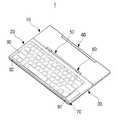
도 1은 본 발명의 일 실시 예에 의한 접이식 컴퓨팅 장치를 나타내는 사시도;
도 2는 본 발명의 일 실시 예에 의한 접이식 컴퓨팅 장치를 터치 모드로 사용하는 경우를 나타낸 사시도;
도 3은 본 발명의 일 실시 예에 의한 접이식 컴퓨팅 장치에서 디스플레이부를 분리하여 본체부만 나타내는 평면도;
도 4는 도 3의 접이식 컴퓨팅 장치에 사용되는 완충 부재를 나타내는 사시도;
도 5는 도 4에 도시된 완충 부재의 측면도;
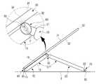
도 6은 본 발명의 일 실시 예에 의한 접이식 컴퓨팅 장치가 터치 모드로 사용되는 경우를 개략적으로 나타내는 측 단면도;
도 7은 본 발명의 일 실시 예에 의한 접이식 컴퓨팅 장치에서 디스플레이부가 지면과 이루는 각도가 도 6의 접이식 컴퓨팅 장치의 디스플레이부의 각도보다 큰 경우를 나타내는 측 단면도;
도 8은 본 발명의 일 실시 예에 의한 접이식 컴퓨팅 장치에서 디스플레이부가 지면과 이루는 각도가 도 6의 접이식 컴퓨팅 장치의 디스플레이부의 각도보다 작은 경우를 나타내는 측 단면도;
도 9는 본 발명의 다른 실시 예에 의한 접이식 컴퓨팅 장치에서 디스플레이부를 분리한 상태를 나타내는 평면도;
도 10은 본 발명의 일 실시 예에 의한 접이식 컴퓨팅 장치에서 제1몸체 및 제2몸체의 내부에 설치되는 회로기판 배치의 일 예를 나타내는 배치도;
도 11은 본 발명의 일 실시 예에 의한 접이식 컴퓨팅 장치에서 제1몸체를 디스플레이부의 후면 쪽으로 회전시키는 상태를 나타내는 사시도;
도 12는 본 발명의 일 실시 예에 의한 접이식 컴퓨팅 장치에서 제1몸체가 디스플레이부의 후면 쪽으로 최대로 회전된 상태를 나타내는 사시도;
도 13은 본 발명의 일 실시 예에 의한 접이식 컴퓨팅 장치를 도 12의 상태에서 제2몸체를 제1몸체에 대해 일정 각도 회전시킨 상태를 나타내는 사시도; 및
도 14는 본 발명의 일 실시 예에 의한 접이식 컴퓨팅 장치의 디스플레이부를 세우는 방법을 나타내는 순서도이다.1 is a perspective view of a foldable computing device according to an embodiment of the present invention;
2 is a perspective view illustrating a case in which the foldable computing device is used in a touch mode according to an embodiment of the present invention;
3 is a plan view showing only a main body part by separating the display unit from the folding computing device according to an embodiment of the present invention;
4 is a perspective view illustrating a cushioning member used in the folding computing device of FIG. 3;
FIG. 5 is a side view of the buffer member shown in FIG. 4; FIG.
FIG. 6 is a side cross-sectional view schematically illustrating a case where a foldable computing device is used in a touch mode according to an embodiment of the present disclosure; FIG.
FIG. 7 is a side cross-sectional view illustrating a case where an angle between a display unit and a ground is greater than an angle of the display unit of the folding computing device of FIG. 6 in the foldable computing device according to an embodiment of the present disclosure; FIG.
FIG. 8 is a side cross-sectional view illustrating a case in which the angle of the display unit with the ground in the foldable computing device is smaller than the angle of the display unit of the foldable computing device of FIG. 6.
9 is a plan view illustrating a state in which a display unit is separated from a folding computing device according to another embodiment of the present invention;
FIG. 10 is a layout view illustrating an example of a circuit board arrangement installed in a first body and a second body in a foldable computing device according to an embodiment of the present disclosure; FIG.
FIG. 11 is a perspective view illustrating a state in which a first body is rotated toward a rear side of a display unit in a folding computing device according to an embodiment of the present disclosure; FIG.
12 is a perspective view illustrating a state in which a first body is rotated to the rear side of a display unit at maximum in a foldable computing device according to an embodiment of the present disclosure;
FIG. 13 is a perspective view illustrating a state in which the foldable computing device according to an embodiment of the present invention is rotated at a predetermined angle with respect to the first body in the state of FIG. 12; And
14 is a flowchart illustrating a method of setting up a display unit of a foldable computing device according to an exemplary embodiment.
이하, 첨부된 도면을 참조하여 본 발명에 의한 접이식 컴퓨팅 장치와 이의 디스플레이부를 세우는 방법의 실시 예들에 대하여 상세하게 설명한다.Hereinafter, exemplary embodiments of a folding computing device and a display unit thereof according to the present invention will be described in detail with reference to the accompanying drawings.
이하에서 설명되는 실시 예는 본 발명의 이해를 돕기 위하여 예시적으로 나타낸 것이며, 본 발명은 여기서 설명되는 실시 예들과 다르게 다양하게 변형되어 실시될 수 있음이 이해되어야 할 것이다. 다만, 이하에서 본 발명을 설명함에 있어서, 관련된 공지 기능 혹은 구성요소에 대한 구체적인 설명이 본 발명의 요지를 불필요하게 흐릴 수 있다고 판단되는 경우 그 상세한 설명 및 구체적인 도시를 생략한다. 또한, 첨부된 도면은 발명의 이해를 돕기 위하여 실제 축척대로 도시된 것이 아니라 일부 구성요소의 치수가 과장되게 도시될 수 있다.Embodiments described below are shown by way of example in order to help understanding of the present invention, it will be understood that the present invention can be implemented in various modifications different from the embodiments described herein. However, in the following description of the present invention, if it is determined that the detailed description of the related known functions or components may unnecessarily obscure the subject matter of the present invention, the detailed description and the detailed illustration will be omitted. In addition, the accompanying drawings may be exaggerated in some of the dimensions of the components rather than being drawn to scale to facilitate understanding of the invention.
도 1은 본 발명의 일 실시 예에 의한 접이식 컴퓨팅 장치를 나타내는 사시도이다. 도 2는 본 발명의 일 실시 예에 의한 접이식 컴퓨팅 장치를 터치 모드로 사용하는 경우를 나타낸 사시도이다. 도 3은 본 발명의 일 실시 예에 의한 접이식 컴퓨팅 장치에서 디스플레이부를 분리한 본체부를 나타내는 평면도이다.1 is a perspective view showing a folding computing device according to an embodiment of the present invention. 2 is a perspective view illustrating a case in which the foldable computing device is used in a touch mode according to an embodiment of the present invention. 3 is a plan view illustrating a main body unit from which a display unit is separated from a folding computing device according to an embodiment of the present disclosure.
도 1 내지 도 3을 참조하면, 본 발명의 일 실시 예에 의한 접이식 컴퓨팅 장치(1)는 제1몸체(10), 제2몸체(20), 및 디스플레이부(30)를 포함한다.1 to 3, a
디스플레이부(30)는 대략 직사각형의 평판 형상으로 형성되며, 전면에는 터치 스크린(31)이 마련된다. 디스플레이부(30)의 후면(32)의 상기 제2몸체(20)의 상단(21)에 의해 지지되는 부분에는 부착 부재(34)가 설치된다. 부착 부재(34)는 자석이 달라붙을 수 있는 자성체로 형성한다. 다른 예로서, 디스플레이부 후면(32)에 별도의 부착 부재(34)를 설치하는 대신에 디스플레이부(30)의 후면(32) 전체를 자성체로 형성할 수 있다. 터치 스크린(31)은 이미지, 문자 등이 디스플레이되며, 터치 스크린(31)을 손으로 터치하여 접이식 컴퓨팅 장치(1)를 조작할 수 있다.The
제1몸체(10)와 제2몸체(20)는 디스플레이부(30)에 대응하는 본체부를 구성한다. 즉, 제1몸체(10)와 제2몸체(20)로 구성되는 본체부는 디스플레이부(30)의 형상과 유사한 형상으로 형성되며, 디스플레이부(30)의 크기와 동일한 크기로 형성된다.The
제1몸체(10)는 디스플레이부(30)의 하단(35)에 회전 가능하게 연결된다. 이를 위해 상기 디스플레이부(30)와 제1몸체(10) 사이에는 제1힌지 유닛(40)이 설치된다. 제1힌지 유닛(40)은 디스플레이부(30)에 대해 제1몸체(10)가 약 360도 회전할 수 있도록 구성된다. 즉, 제1힌지 유닛(40)은 터치 스크린(31)이 설치된 디스플레이부(30)의 전면과 제1몸체(10)의 상면(18)이 접촉한 상태에서 제1몸체(10)의 하면(19)이 디스플레이부(30)의 후면(32)과 접촉하거나 근접한 상태(도 2 참조)까지 제1몸체(10)가 회전할 수 있도록 한다.The
일 예로서, 제1힌지 유닛(40)은 힌지 부재(41)를 포함할 수 있다. 힌지 부재(41)는 긴 막대 형상으로 형성되며, 힌지 부재(41)의 양단에는 각각 2개의 힌지 축(42)이 설치된다. 디스플레이부(30)의 하단(35)과 제1몸체(10)의 상단(11)에는 힌지 부재(41)가 설치될 수 있도록 제1힌지 홈(36)과 제2힌지 홈(13)이 형성된다. 디스플레이부(30)에 형성된 제1힌지 홈(36)의 양 측면에는 각각 한 개의 힌지 구멍(37)이 형성되어 있다. 또한, 제1몸체(10)에 형성된 제2힌지 홈(13)의 양 측면에도 각각 한 개의 힌지 구멍(14)이 형성되어 있다. 힌지 구멍(37)은 힌지 부재(41)의 힌지 축(42)이 삽입되어 회전할 수 있도록 형성된다. 따라서, 힌지 부재(41)의 양단에 마련된 2개의 힌지 축(42)은 각각 제1힌지 홈(36)과 제2힌지 홈(13)에 형성된 힌지 구멍(37,14)에 삽입된다. 따라서, 제1몸체(10)는 제1힌지 유닛(40)에 의해 디스플레이부(30)에 대해 대략 360도 회전할 수 있다. 여기서, 힌지 부재(41)에 힌지 축(42)이 형성되고, 제1힌지 홈(36)과 제2힌지 홈(13)의 양 측면에 힌지 구멍(37,14)이 형성된 것으로 설명하였으나, 반대의 경우도 가능하다. 즉, 힌지 부재(41)에 힌지 구멍을 형성하고, 제1힌지 홈(36)과 제2힌지 홈(13)의 양 측면에 힌지 축을 형성하는 것도 가능하다.As an example, the
또한, 제1힌지 유닛(40)은 제1몸체(10)가 디스플레이부(30)에 대해 일정 각도 회전한 상태에서 제1몸체(10)가 회전하지 못하도록 고정하는 제1고정 수단(미도시)을 더 포함할 수 있다. 따라서, 사용자가 제1몸체(10)에 힘을 가하면, 제1몸체(10)가 회전하여 디스플레이부(30)와 제1몸체(10) 사이의 각도를 조절할 수 있고, 사용자가 힘을 가하지 않으면 제1몸체(10)가 회전하여 조절된 각도를 유지한다. 제1고정 수단은 종래의 노트북 컴퓨터의 힌지 유닛에 사용되는 고정 수단과 동일하거나 유사한 것을 사용할 수 있으므로, 이에 대한 상세한 설명은 생략한다.In addition, the
도 3을 참조하면, 제1몸체(10)의 상단(11)에는 제2힌지 홈(13)의 양측으로 제1미끄럼 방지 부재(81)가 설치될 수 있다. 제1미끄럼 방지 부재(81)는 도 2와 같이 본 발명의 일 실시 예에 의한 접이식 컴퓨팅 장치(1)의 디스플레이부(30)를 지면(3)에 세울 때, 지면(3)에 접촉하는 제1몸체(10)의 상단(11)에 설치되어, 디스플레이부(30)가 미끄러지는 것을 방지한다. 따라서, 제1미끄럼 방지 부재(81)는 마찰계수가 큰 재질로 형성한다. 예를 들면, 제1미끄럼 방지 부재(81)는 고무로 형성할 수 있다. 여기서, 지면(3)은 책상의 상면, 방 바닥, 마루 바닥과 같이 본 발명에 의한 접이식 컴퓨팅 장치(1)의 디스플레이부(30)를 세울 수 있는 모든 평평한 장소를 말한다.Referring to FIG. 3, the first
상기 제1몸체(10)와 제2몸체(20) 사이에는 제2힌지 유닛(50)이 설치된다. 제2힌지 유닛(50)은 제2몸체(20)가 제1몸체(10)에 대해 최대 180도까지 회전할 수 있도록 한다. 이때, 제2힌지 유닛(50)에 의해 도 1에 도시된 바와 같이 제2몸체(20)는 제1몸체(10)와 동일한 평면에 위치한 상태에서 상측으로 회전할 수 있다(도 13 참조).A
일 예로서, 제2힌지 유닛(50)은 힌지 축(51)과 힌지 구멍(52)으로 형성될 수 있다. 도 3을 참조하면, 제1몸체(10)의 하단(12)에는 수용 홈(15)이 마련되고, 제2몸체(20)의 상단에는 제1몸체(10)의 수용 홈(15)에 삽입되는 돌출부(21)가 형성된다. 제2몸체(20)의 돌출부(21)의 양 측면에는 힌지 축(51)이 설치된다. 또한, 제1몸체(10)의 수용 홈(15)의 양 측면에는 제2몸체(20)의 돌출부(21)의 힌지 축(51)에 대응하는 힌지 구멍(52)이 형성된다. 힌지 구멍(52)은 돌출부(21)의 힌지 축(51)이 삽입되어 회전할 수 있도록 형성된다. 도 3에서는 제1몸체(10)의 수용 홈(15)에 힌지 구멍(52)이 형성되고, 제2몸체(20)의 돌출부(21)에 힌지 축(51)이 형성된 경우를 예로 들어 설명하였으나, 반대의 경우도 가능하다. 즉, 제1몸체(10)의 수용 홈(15)에 힌지 축을 형성하고, 제2몸체(20)의 돌출부(21)에 힌지 구멍을 형성하는 것도 가능하다.As an example, the
또한, 제2힌지 유닛(50)은 제2몸체(20)가 제1몸체(10)에 대해 일정 각도 회전한 상태에서 제2몸체(20)가 회전하지 못하도록 고정하는 제2고정 수단(미도시)을 더 포함할 수 있다. 따라서, 사용자가 제2몸체(20)에 힘을 가하면, 제2몸체(20)가 제1몸체(10)에 대해 회전하여 제1몸체(10)와 제2몸체(20) 사이의 각도(θ1)를 조절할 수 있고, 사용자가 힘을 가하지 않으면 제2몸체(20)가 회전하여 조절된 각도를 그대로 유지할 수 있다. 제2고정 수단은 종래의 노트북 컴퓨터의 힌지 유닛에 사용되는 고정 수단과 동일하거나 유사한 것을 사용할 수 있으므로, 이에 대한 상세한 설명은 생략한다.In addition, the
또한, 제2몸체(20)의 돌출부(21)의 상부에는 복수 개의 완충 부재(60)가 설치될 수 있다. 따라서, 제2몸체(20)를 제1몸체(10)에 대해 회전시키면, 제2몸체(20)의 돌출부(21)에 마련된 복수 개의 완충 부재(60)가 돌출되고, 제2몸체(20)가 제1몸체(10)와 동일 평면에 위치하면 복수 개의 완충 부재(60)가 제1몸체(10)의 하단(12)과 제2몸체(20)의 돌출부(21) 사이에 위치하여 돌출되지 않는다. 복수 개의 완충 부재(60)는 도 2와 같이 접이식 컴퓨팅 장치(1)의 디스플레이부(30)를 지면(3)에 대해 세울 때, 디스플레이부(30)를 지지하여 디스플레이부(30)의 터치 스크린(31)을 터치하는 힘을 흡수한다.In addition, a plurality of
도 4 및 도 5에는 완충 부재의 일 예가 도시되어 있다. 도 4는 본 발명의 일 실시 예에 의한 접이식 컴퓨팅 장치에 사용되는 완충 부재를 나타내는 사시도이고, 도 5는 도 4에 도시된 완충 부재의 측면도이다.4 and 5 show an example of the buffer member. 4 is a perspective view illustrating a shock absorbing member used in a foldable computing device according to an embodiment of the present invention, and FIG. 5 is a side view of the shock absorbing member shown in FIG. 4.
완충 부재(60)는 하우징(61)과 스프링(62)으로 구성될 수 있다. 하우징(61)은 고무와 같은 탄성 재료로 형성되어 힘을 받으면 변형될 수 있다. 하우징(61)은 도 4 및 도 5에 도시된 바와 같이 대략 타원의 단면을 갖는 롤러 형상으로 형성될 수 있다. 다른 예로서, 도시하지는 않았지만, 하우징(61)은 대략 원형 단면을 갖는 롤러 형상으로 형성될 수도 있다.The
하우징(61)의 양 측면에는 회전 샤프트(63)가 설치된다. 제2몸체(20)의 돌출부(21)에는 완충 부재(60)가 설치되는 완충 부재 장착 홈(26)이 형성된다. 본 실시 예의 경우에는 2개의 완충 부재(60)를 사용하므로 제2몸체(20)에도 2개의 완충 부재 장착 홈(26)이 마련된다. 완충 부재 장착 홈(26)의 양 측면에는 완충 부재(60)의 회전 샤프트(63)가 삽입되는 회전 구멍(27)이 형성된다. 따라서, 완충 부재(60)의 회전 샤프트(63)를 완충 부재 장착 홈(26)의 회전 구멍(27)에 조립하면, 완충 부재(60)는 회전 샤프트(63)를 중심으로 회전할 수 있다.Rotating
또한, 하우징(61)의 내부에는 하우징(61)의 탄성을 보조할 수 있도록 코일 스프링(62)이 설치될 수 있다. 코일 스프링(62)은 타원 형상의 하우징(61)의 장축 방향(C)을 따라 신축 동작을 하도록 하우징(61) 내부에 설치된다. 즉, 하우징(61)의 장축 방향(C)과 스프링(62)의 작동 방향이 일치하도록 형성된다. 따라서, 완충 부재(60)의 장축 방향(C)의 일 단에 힘이 인가되면, 하우징(61)과 스프링(62)이 함께 힘을 흡수하여 충격을 완충할 수 있다.In addition, a
또한, 하우징(61)의 내부에 하우징(61)의 장축 방향(C)의 일단 부근에는 영구 자석(65)이 설치된다. 영구 자석(65)은 디스플레이부(30)의 부착 부재(34)가 근접하면, 회전 샤프트(63)를 중심으로 완충 부재(60)를 회전시킬 수 있는 크기의 자력을 갖는다. 영구 자석(65)은 도 4 및 도 5에 도시된 바와 같이 하우징(61)의 내부에 설치된 스프링(62)의 상측에 위치하도록 설치된다. 따라서, 영구 자석(65)에 의해 하우징(61)의 장축 방향(C)의 일단이 디스플레이부(30)의 부착 부재(34)에 접촉하면, 디스플레이부(30)에 작용하는 힘이 스프링(62)의 작동 방향과 대략 평행하게 작용하게 된다. 즉, 디스플레이부(30)의 부착 부재(34)와 완충 부재(60)의 영구 자석(65)에 의해 하우징(61)의 장축 방향(C)과 디스플레이부(30)의 후면(32)이 대략 직각을 이루게 된다. 또한, 디스플레이부(30)의 부착 부재(34)와 완충 부재(60)의 영구 자석(65) 사이에 작용하는 자력에 의해 완충 부재(60)가 회전 샤프트(63)를 중심으로 회전하므로, 제1몸체(10)와 제2몸체(20) 사이의 각도(θ1)가 변화하여 디스플레이부(30)와 제2몸체(20) 사이의 각도(θ2)가 변화하는 경우에도, 완충 부재(60)의 장축 방향(C)은 디스플레이부(30)의 후면(32)과 대략 직각을 유지할 수 있다.In addition, a
이하, 제2몸체(20)와 제1몸체(10) 사이의 각도(θ1)가 변하여도 완충 부재(60)의 장축 방향(C)이 디스플레이부(30)의 후면(32)에 대해 대략 수직을 이루도록 완충 부재(60)가 작동하는 것을 도 6 내지 도 8을 참조하여 설명한다.Hereinafter, even if the angle θ1 between the
도 6은 본 발명의 일 실시 예에 의한 접이식 컴퓨팅 장치가 터치 모드로 사용되는 경우를 개략적으로 나타내는 측 단면도이고, 도 7은 본 발명의 일 실시 예에 의한 접이식 컴퓨팅 장치에서 디스플레이부가 지면과 이루는 각도가 도 6의 접이식 컴퓨팅 장치의 디스플레이부의 각도보다 큰 경우를 나타내는 측 단면도이다. 도 8은 본 발명의 일 실시 예에 의한 접이식 컴퓨팅 장치에서 디스플레이부가 지면과 이루는 각도가 도 6의 접이식 컴퓨팅 장치의 디스플레이부의 각도보다 작은 경우를 나타내는 측 단면도이다.FIG. 6 is a side cross-sectional view schematically illustrating a case in which a foldable computing device is used in a touch mode, and FIG. 7 is an angle of the display unit with the ground in the foldable computing device according to an embodiment of the present invention. Is a side cross-sectional view showing a case where the angle of the display unit of the folding computing device of FIG. FIG. 8 is a side cross-sectional view illustrating a case in which the angle of the display unit with the ground in the foldable computing device is smaller than the angle of the display unit of the foldable computing device of FIG. 6.
도 6을 참조하면, 제2몸체(20)가 제1몸체(10)와 대략 직각을 이룬 상태에서 제2몸체(20)가 디스플레이부(30)를 지지하고 있다. 이때, 디스플레이부(30)의 부착 부재(34)는 자성체로 되어 있으므로, 부착 부재(34)와 완충 부재(60)의 영구 자석(65) 사이에는 자기력이 작용하여, 영구 자석(65)이 설치된 완충 부재(60)의 일단이 디스플레이부(30)의 부착 부재(34)에 접촉하게 된다. 영구 자석(65)은 완충 부재(60)의 장축 방향(C)의 일단, 즉 완충 부재(60)의 내부에 설치된 스프링(62)의 상측에 설치되므로 완충 부재(60)의 스프링(62)이 디스플레이부(30)의 후면(32)에 대해 대략 수직하게 위치하게 된다. 따라서, 사용자가 터치할 때 디스플레이부(30)에 인가되는 힘을 완충 부재(60)가 효과적으로 흡수할 수 있다. 이때, 완충 부재(60)의 장축 방향(C)은 제2몸체(20)와 대략 평행을 이루게 된다.Referring to FIG. 6, the
도 7은 디스플레이부(30)가 지면(3)에 대해 도 6보다 더 수직하게 세워진 경우를 나타낸다. 이 경우에 제1몸체(10)와 제2몸체(20) 사이의 각도(θ1)는 도 6에 도시된 접이식 컴퓨팅 장치(1)의 제1몸체(10)와 제2몸체(20) 사이의 각도(θ1)보다 작다. 즉 제1몸체(10)와 제2몸체(20) 사이 각(θ1)이 예각을 이룬다. 이 경우에도 완충 부재(60)의 영구 자석(65)과 디스플레이부(30)의 후면(32)에 설치된 부착 부재(34) 사이에 자력이 작용하므로, 도 7에 도시된 바와 같이 완충 부재(60)의 장축 방향(C)이 디스플레이부(30)의 후면(32)에 대해 대략 수직한 상태를 이루게 된다. 이때, 완충 부재(60)의 장축 방향(C)은 제2몸체(20)와 일정 각도를 이루며, 지면(3)에 평행한 방향으로 회전한다.FIG. 7 illustrates a case in which the
또한, 도 8은 디스플레이부(30)가 도 6의 경우보다 지면(3)에 더 가깝게 누여진 경우를 나타낸다. 이 경우에 제1몸체(10)와 제2몸체(20) 사이의 각도(θ1")는 도 6에 도시된 접이식 컴퓨팅 장치(1)의 제1몸체(10)와 제2몸체(20) 사이의 각도(θ1)보다 크다. 즉 제1몸체(10)와 제2몸체 사이 각(θ1")이 둔각을 이룬다. 이 경우에도 완충 부재(60)의 영구 자석(65)과 디스플레이부(30)의 후면(32)에 설치된 부착 부재(34) 사이에 자력이 작용하므로, 도 8에 도시된 바와 같이 완충 부재(60)의 장축 방향(C)이 디스플레이부(30)의 후면(32)에 대해 대략 수직한 상태를 이루게 된다. 따라서, 디스플레이부(30)에 인가되는 힘을 완충 부재(60)가 효과적으로 흡수할 수 있다. 이때, 완충 부재(60)의 장축 방향(C)은 제2몸체(20)와 일정 각도를 이루며, 지면(3)에 수직한 방향으로 회전한다.8 illustrates a case in which the
다시, 도 3을 참조하면, 제2몸체(20)의 하단(22)에는, 즉 제2몸체(20)의 돌출부(21)의 반대쪽 측면에는 완충장치(70)가 설치될 수 있다. 완충장치(70)는 도 2와 같이 디스플레이부(30)가 지면(3)에 대해 세워졌을 때, 터치 스크린(31)에 인가되는 힘을 지지하는 제2몸체(20)에 인가되는 힘을 감소시키는 역할을 한다.Again, referring to FIG. 3, a
완충장치(70)는 완충 판(71)과 완충 판(71)을 지지하는 복수 개의 탄성 부재(72)를 포함한다. 완충 판(71)은 제2몸체(20)의 하단(22)에 대응하는 크기와 형상을 갖는 평판으로 형성될 수 있다. 복수 개의 탄성 부재(72)는 제2몸체(20)의 하단(22)에 설치된다. 탄성 부재(72)의 일단은 제2몸체(20)의 하단(22)에 고정되고, 타단은 완충 판(71)에 고정된다. 따라서, 도 2와 같이 제2몸체(20)를 디스플레이부(30)에 대해 소정 각도 회전시켜 제2몸체(20)로 디스플레이부(30)를 지지하는 경우에 완충장치(70)의 완충 판(71)이 지면(3)과 접촉하므로 디스플레이부(30)에 인가되는 힘을 완충장치(70)가 흡수할 수 있다.The
본 실시 예의 경우에는 2개의 탄성 부재(72)를 사용하고, 탄성 부재(72)로 코일 스프링을 사용한다. 그러나, 탄성 부재(72)의 개수와 종류는 이에 한정되는 것은 아니다. 3개 이상의 탄성 부재(72)를 사용할 수 있으며, 탄성 부재(72)로 판 스프링을 사용할 수도 있다.In this embodiment, two
또한, 완충 판(71)에는 복수 개의 제2미끄럼 방지 부재(82)가 설치될 수 있다. 제2미끄럼 방지 부재(82)는 도 2와 같이 본 발명에 의한 접이식 컴퓨팅 장치(1)의 디스플레이부(30)를 지면(3)에 세울 때 지면(3)에 접촉하는 완충 판(71)에 설치되어, 디스플레이부(30)가 미끄러지는 것을 방지한다. 본 실시 예의 경우에는 2개의 제2미끄럼 방지 부재(82)가 일정 거리 이격 되어 완충 판(71)에 설치되어 있다. 그러나, 제2미끄럼 방지 부재(82)의 개수는 2개로 한정되는 것은 아니며, 필요에 따라 2개 이상의 제2미끄럼 방지 부재(82)를 완충 판(71)에 설치할 수 있다. 또한, 제2미끄럼 방지 부재(82)는 디스플레이부(30)의 미끄럼을 방지하기 위해 마찰계수가 큰 재질로 형성한다. 예를 들면, 제2미끄럼 방지 부재(82)는 제1미끄럼 방지 부재(81)와 동일하게 고무로 형성할 수 있다.In addition, a plurality of second
다른 실시 예로서, 제2몸체(20)의 돌출부(21)에 설치된 복수 개의 완충 부재(60)로 터치 스크린(31)에 인가되는 힘을 충분하게 흡수할 수 있는 경우에는 제2몸체(20)의 하단(22)에 완충장치(70)를 설치하지 않을 수 있다. 제2몸체(20)에 완충장치(70)가 설치되지 않은 접이식 컴퓨팅 장치(1)가 도 9에 도시되어 있다.As another example, when the force applied to the
도 9를 참조하면, 제2미끄럼 방지 부재(82)는 제2몸체(20)의 하단(22), 즉, 돌출부(21)의 반대쪽 측면에 설치된다. 따라서, 도 2와 같이 본 발명에 의한 접이식 컴퓨팅 장치(1)의 디스플레이부(30)를 지면(3)에 세울 때 제2몸체(20)의 하단(22)에 설치된 제2미끄럼 방지 부재(82)가 지면(3)과 접촉하므로, 디스플레이부(30)가 미끄러지는 것을 방지할 수 있다. 도 9에 도시된 제2미끄럼 방지 부재(82)는 설치 위치만 상술한 실시 예에 의한 제2미끄럼 방지 부재(82)와 다를 뿐이고 그 외의 것은 동일하다. 따라서, 이에 대한 상세한 설명은 생략한다.Referring to FIG. 9, the second
제1몸체(10)와 제2몸체(20)의 내부에는 접이식 컴퓨팅 장치(1)가 다양한 기능을 수행할 수 있도록 하는 여러 가지 부품이 설치될 수 있다. 즉, 제1몸체(10)와 제2몸체(20)의 내부에는 전원부, 연산부, 저장부, 인터페이스부를 구성하는 기판이 적절하게 설치될 수 있다.Inside the
도 10은 본 발명의 일 실시 예에 의한 접이식 컴퓨팅 장치에서 제1몸체 및 제2몸체의 내부에 설치되는 회로기판의 배치 예를 나타내는 배치도이다.FIG. 10 is a layout view illustrating an arrangement example of a circuit board installed in the first body and the second body in the foldable computing device according to an embodiment of the present disclosure.
도 10을 참조하면, 제1몸체(10)에는 메인 기판(93)과 인터페이스 기판(94)이 설치되고, 제2몸체(20)에는 키보드(90), 터치 패드(91), 서브 기판(95)이 설치된다.Referring to FIG. 10, a
메인 기판(93)은 CPU, RAM, ROM 등을 포함하는 인쇄회로기판으로 이루어지며, 본 발명에 의한 접이식 컴퓨팅 장치(1)가 다양한 기능을 수행할 수 있도록 하는 연산부를 포함한다. 따라서, 메인 기판(93)은 키보드(90), 터치 스크린(31)과 같은 입력장치로부터 명령을 받고, 이를 처리하여 그 결과를 디스플레이부(30)의 터치 스크린(31)에 디스플레이하거나, 저장부(미도시)에 저장하거나, 외부로 출력한다. 인터페이스 기판(94)이 메인 기판(93)에 연결될 수 있다. 도시하지는 않았으나, 저장부가 메인 기판(93)에 연결될 수 있다. 다른 예로서, 인터페이스 기판(94)과 저장부는 메인 기판(93)과 일체로 형성될 수도 있다. 메인 기판(93)은 일반적인 노트북 컴퓨터에서 사용되는 메인 기판과 동일하거나 유사한 것을 사용할 수 있으므로 상세한 설명은 생략한다.The
저장부(미도시)는 접이식 컴퓨팅 장치(1)를 동작시키기 위해 필요한 프로그램, 사용자가 작성한 문서, 이미지, 동영상 등의 데이터를 저장하는 것으로서, 종래의 노트북 컴퓨터에서 사용되는 메모리, 하드 디스크 등의 저장장치를 사용할 수 있으므로 상세한 설명은 생략한다.The storage unit (not shown) stores data required for operating the
인터페이스 기판(94)은 외부의 주변장치와 본 발명에 의한 접이식 컴퓨팅 장치(1)를 연결하는 것으로서, 적어도 한 개의 USB 포트, 음성 입출력단자, 화상 입출력단자, 전원단자 등을 포함할 수 있다. 인터페이스 기판(94)은 종래의 노트북 컴퓨터에 사용되는 인터페이스 기판과 유사하거나 동일하게 구성할 수 있으므로 상세한 설명은 생략한다.The
전원부(미도시)는 접이식 컴퓨팅 장치(1)를 구성하는 메인 기판(93), 저장부(미도시), 디스플레이부(30)에 전원을 공급하는 것으로서, 다양한 전원 공급장치가 사용될 수 있다. 예를 들면, 전원부로서 충전 배터리가 사용될 수 있다. 또한, 전원부는 상용 전원으로부터 전기를 공급받아 다른 부품들에 공급할 수 있도록 구성될 수 있다. 전원부는 제1몸체(10)의 메인 기판(93) 아래에 또는 제2몸체(20)의 키보드(90) 아래에 설치될 수 있다. 전원부는 일반적인 노트북 컴퓨터에서 사용되는 전원부와 동일하거나 유사한 것을 사용할 수 있으므로 상세한 설명은 생략한다.The power supply unit (not shown) supplies power to the
제2몸체(20)의 상면에는 키보드(keyboard)(90)가 설치된다. 키보드(90)는 본 발명에 의한 접이식 컴퓨팅 장치(1)에 문자, 기호 등을 입력할 수 있는 입력 장치이다.The
또한, 제2몸체(20)의 상면에는 키보드(90)와 함께 터치 패드(touch pad)(91)를 설치할 수 있다. 제2몸체(20)는 종래의 노트북 컴퓨터의 본체부보다 면적이 작으므로, 키보드(90)와 터치 패드(91)를 함께 설치하기 위한 공간이 작다. 따라서, 터치 패드(91)는 종래의 노트북 컴퓨터에 비해 작은 사이즈의 터치 패드(91)를 사용한다. 또는 터치 패드(91) 대신에 트랙 볼(track ball)을 사용할 수 있다.In addition, a
또한, 제2몸체(20)에는 USB 포트(97)를 설치할 수 있다. 제2몸체(20)의 내부에 키보드(90), 터치 패드(91), 및 USB 포트(97)를 연결하는 서브 기판(95)을 설치할 수 있다. 서브 기판(95)은 플렉시블 케이블(96)에 의해 제1몸체(10)의 내부에 설치된 메인 기판(93)에 연결될 수 있다.In addition, a
이하, 상기와 같은 구조를 갖는 본 발명에 의한 접이식 컴퓨팅 장치(1)의 디스플레이부(30)를 세우는 방법에 대해 첨부된 도 1, 도 2, 도 11 내지 도 14를 참조하여 설명한다.Hereinafter, a method of setting up the
본 발명에 의한 접이식 컴퓨팅 장치(1)는 2가지 모드로 사용할 수 있다. 즉, 본 발명에 의한 접이식 컴퓨팅 장치(1)를 도 1에 도시된 바와 같이 일반적인 노트북 컴퓨터와 동일한 방법으로 사용할 수 있는 키보드 모드와 도 2에 도시된 바와 같이 터치 스크린(31)을 사용하여 접이식 컴퓨팅 장치(1)를 제어하는 터치 모드가 있다.The
키보드 모드에서는 도 1과 같이 제1몸체(10)와 제2몸체(20)가 동일 평면에 있고, 디스플레이부(30)가 제1회전 유닛(40)에 의해 회전하여 제1몸체(10)에 대해 소정 각도 열린 상태가 된다. 따라서, 사용자는 키보드(90)를 사용하여 데이터를 입력하거나 접이식 컴퓨팅 장치(1)를 제어할 수 있다. 그러나, 이 상태는 제1힌지 유닛(40)만으로 디스플레이부(30)를 지지하므로, 터치 스크린(31)을 터치하면, 디스플레이부(30)가 안정적으로 지지되지 않는다.In the keyboard mode, as shown in FIG. 1, the
따라서, 터치 스크린(31)을 주로 사용하고자 하는 경우에는, 사용자는 도 2에 도시된 바와 같이 접이식 컴퓨팅 장치(1)의 디스플레이부(10)를 제1몸체(10)와 제2몸체(20)로 세워서 지지하는 터치 모드로 전환한다.Accordingly, when the
본 발명에 의한 접이식 컴퓨팅 장치(1)의 디스플레이부(30)를 제1몸체(10)와 제2몸체(20)로 세워서 지지하는 방법은 다음과 같다.The method of supporting the
사용자는 도 1과 같이 키보드 모드로 사용하는 접이식 컴퓨팅 장치(1)의 제1몸체(10)를 디스플레이부(30)에 대해 회전시킨다. 또는 디스플레이부(30)가 제1몸체(10)와 제2몸체(20)를 덮고 있는 상태, 즉 디스플레이부(30)의 터치 스크린(31)과 제2몸체(20)의 키보드(90)가 서로 마주하도록 인접한 상태에서, 제1몸체(10)를 터치 스크린(31)과 멀어지도록 디스플레이부(30)에 대해 회전시킨다. 즉, 도 11에 도시된 바와 같이, 제1몸체(10)와 제2몸체(20)를 디스플레이부(30)의 터치 스크린(31)과 반대 방향으로 회전시킨다. 이때, 제1몸체(10)와 디스플레이부(30) 사이에는 제1힌지 유닛(40)이 설치되어 있으므로, 제1몸체(10)는 디스플레이부(30)에 대해 대략 360도 회전할 수 있다.As shown in FIG. 1, the user rotates the
디스플레이부(30)에 대해 제1몸체(10)와 제2몸체(20)를 완전히 회전시키면, 도 12와 같이 제1몸체(10)의 후면(19)과 제2몸체(20)의 후면이 디스플레이부(30)의 후면(32)과 접촉하거나 매우 근접한 상태가 된다. 그 결과, 도 12에 도시된 접이식 컴퓨팅 장치(1)의 경우에는 상측으로는 키보드(90)가 노출되고, 하측으로는 디스플레이부(30)의 터치 스크린(31)이 노출된다. 이때, 제1몸체(10)의 상단(11)에 있는 제1미끄럼 방지 부재(81)가 노출된 상태이다.When the
이 상태에서, 사용자는 도 13에 도시된 바와 같이 제2몸체(20)를 제1몸체(10)에 대해 회전시킨다. 제2몸체(20)를 제1몸체(10)에 대해 대략 90도 정도 회전시킨 후, 제1몸체(10)의 상단(11)과 제2몸체(20)의 하단(22)을 지면(3)에 놓으면, 도 2에 도시된 바와 같이 디스플레이부(30)가 지면(3)에 세워진 상태가 된다. 제2몸체(20)를 제1몸체(10)에 대해 회전시키면, 제2몸체(20)의 돌출부(21)에 설치된 완충 부재(60)가 노출되어 디스플레이부(30)의 후면(32)을 지지하게 된다. 이때, 완충 부재(60)의 일단에 설치된 영구 자석(65)과 디스플레이부(30) 후면(32)의 부착 부재(34) 사이에는 자력이 작용하므로, 완충 부재(60)의 충격 흡수 방향, 즉 완충 부재(60)의 장축 방향(C)이 디스플레이부 후면(32)과 대략 수직하게 된다. 또한, 지면(3)과 접촉하는 제2몸체(20)의 하단(22)에는 완충장치(70)와 제2미끄럼 방지 부재(82)가 설치되어 있고, 제1몸체(10)의 상단(11)에는 제1미끄럼 방지 부재(81)가 설치되어 있으므로, 제1몸체(10)와 제2몸체(20)가 디스플레이부(30)를 안정적으로 지지할 수 있다.In this state, the user rotates the
이 상태에서 사용자는 디스플레이부(30)의 터치 스크린(31)을 터치하여 접이식 컴퓨팅 장치(1)를 제어할 수 있다. 이때, 사용자가 손으로 터치 스크린(31)을 터치할 때 인가되는 힘은 제2몸체(20)에 의해 지지되므로 사용자는 안정적으로 터치 스크린(31)을 터치할 수 있다.In this state, the user may control the
특히, 본 발명에 의한 접이식 컴퓨팅 장치(1)는 디스플레이부(30)의 후면(32)과 제2몸체(20)의 상단 사이에 복수 개의 완충 부재(60)가 설치되어 있으므로, 터치시 인가되는 힘을 효과적으로 흡수할 수 있다. 따라서, 사용자는 터치 작업을 안정적으로 할 수 있다.In particular, since the plurality of
또한, 본 발명에 의한 접이식 컴퓨팅 장치(1)는 지면(3)과 접촉하는 제1몸체(10)의 상단(11)과 제2몸체(20)의 하단(22)에 복수 개의 미끄럼 방지 부재(81,82)가 설치되어 있으므로, 터치 스크린(31)을 터치할 때, 접이식 컴퓨팅 장치(1)가 지면에서 미끄러지는 것을 억제할 수 있다.In addition, the
상기에서 본 발명은 예시적인 방법으로 설명되었다. 여기서 사용된 용어들은 설명을 위한 것이며, 한정의 의미로 이해되어서는 안 될 것이다. 상기 내용에 따라 본 발명의 다양한 수정 및 변형이 가능하다. 따라서 따로 부가 언급하지 않는 한 본 발명은 청구범위의 범주 내에서 자유로이 실시될 수 있을 것이다.
In the above, the present invention has been described by way of example. The terminology used herein is for the purpose of description and should not be regarded as limiting. Many modifications and variations of the present invention are possible in light of the above teachings. Accordingly, unless otherwise stated, the invention may be practiced freely within the scope of the claims.
1; 접이식 컴퓨팅 장치3; 지면
10; 제1몸체13; 제2힌지 홈
20; 제2몸체21; 돌출부
30; 디스플레이부31; 터치 스크린
34; 부착 부재36; 제1힌지 홈
40; 제1힌지 유닛41; 힌지 부재
42; 힌지 축50; 제2힌지 유닛
60; 완충 부재61; 하우징
62; 스프링63; 회전 샤프트
65; 영구 자석70; 완충장치
71; 완충 판72; 탄성부재
81; 제1미끄럼 방지 부재82; 제2미끄럼 방지 부재
90; 키보드91; 터치 패드
93; 메인 기판94; 인터페이스 기판One;
10;
20;
30; A
34;
40;
42;
60;
62;
65;
71;
81; First
90;
93;
Claims (16)
Translated fromKorean상기 디스플레이부의 일단에 회전 가능하게 설치되는 제1몸체;
상기 디스플레이부와 반대쪽으로 상기 제1몸체의 일단에 회전 가능하게 설치되며, 키보드를 포함하는 제2몸체;를 포함하며,
상기 디스플레이부의 후면과 상기 제1몸체의 후면이 인접하도록 상기 제1몸체를 회전시킨 상태에서, 상기 제2몸체를 상기 제1몸체에 대해 회전시켜 상기 디스플레이부를 지지하고,
상기 제1몸체와 인접한 상기 제2몸체의 일단에는 완충 부재가 설치되고,
상기 제2몸체가 제1몸체에 대해 회전하는 각도와 관계 없이 완충부재의 일단은 디스플레이부의 후면을 향하는 접이식 컴퓨팅 장치.A display unit including a touch screen;
A first body rotatably installed at one end of the display unit;
A second body rotatably installed at one end of the first body opposite to the display unit and including a keyboard;
The second body is rotated with respect to the first body to support the display unit while the first body is rotated such that a rear surface of the display unit and a rear surface of the first body are adjacent to each other.
One end of the second body adjacent to the first body is provided with a buffer member,
And one end of the buffer member faces a rear surface of the display unit regardless of an angle at which the second body rotates with respect to the first body.
상기 디스플레이부와 인접한 상기 제1몸체의 일단에는 제1미끄럼 방지 부재가 설치된 것을 특징으로 하는 접이식 컴퓨팅 장치.The method of claim 1,
And a first non-slip member is provided at one end of the first body adjacent to the display unit.
상기 제1몸체와 반대쪽으로 지면과 접촉되는 상기 제2몸체의 일단에는 제2미끄럼 방지 부재가 설치된 것을 특징으로 하는 접이식 컴퓨팅 장치.The method according to claim 1 or 2,
And a second non-slip member is provided at one end of the second body in contact with the ground in a direction opposite to the first body.
상기 완충 부재는 고무로 형성된 하우징; 및
상기 하우징 내부에 설치된 스프링;을 포함하는 것을 특징으로 하는 접이식 컴퓨팅 장치.The method of claim 1,
The shock absorbing member includes a housing formed of rubber; And
And a spring installed in the housing.
상기 완충 부재는 상기 하우징의 내부에 상기 스프링 상측에 설치된 자석을 더 포함하며,
상기 디스플레이부의 후면에는 상기 자석이 부착되는 자성체가 설치된 것을 특징으로 하는 접이식 컴퓨팅 장치.The method of claim 5,
The buffer member further includes a magnet installed above the spring inside the housing,
The rear side of the display unit is a folding computing device, characterized in that the magnetic material is attached to the magnet is installed.
상기 디스플레이부와 상기 제1몸체 사이에는 제1힌지 유닛이 설치되며,
상기 제1몸체와 상기 제2몸체 사이에는 제2힌지 유닛이 설치된 것을 특징으로 하는 접이식 컴퓨팅 장치.The method of claim 1,
A first hinge unit is installed between the display unit and the first body.
And a second hinge unit is installed between the first body and the second body.
상기 제1힌지 유닛은 상기 제1몸체가 상기 디스플레이부에 대해 360도 회전할 수 있도록 하고,
상기 제2힌지 유닛은 상기 제2몸체가 상기 제1몸체에 대해 180도 회전할 수 있도록 하는 것을 특징으로 하는 접이식 컴퓨팅 장치.The method of claim 7, wherein
The first hinge unit allows the first body to rotate 360 degrees with respect to the display unit,
And the second hinge unit allows the second body to rotate 180 degrees with respect to the first body.
상기 제1몸체와 반대쪽으로 지면과 접촉하는 상기 제2몸체의 일단에는 완충장치가 설치된 것을 특징으로 하는 접이식 컴퓨팅 장치.The method of claim 1,
And a shock absorber is installed at one end of the second body in contact with the ground in a direction opposite to the first body.
상기 완충장치에는 제2미끄럼 방지 부재가 설치된 것을 특징으로 하는 접이식 컴퓨팅 장치.The method of claim 9,
And a second non-slip member is installed in the shock absorber.
상기 완충장치는 상기 제2몸체의 일단에 설치되는 복수 개의 탄성 부재; 및
상기 복수 개의 탄성 부재에 의해 지지되는 완충 판;을 포함하는 것을 특징으로 하는 접이식 컴퓨팅 장치.The method of claim 9,
The shock absorber includes a plurality of elastic members installed at one end of the second body; And
And a buffer plate supported by the plurality of elastic members.
상기 제1몸체에는 메인 기판이 설치되는 것을 특징으로 하는 접이식 컴퓨팅 장치.The method of claim 1,
The first body is a folding computing device, characterized in that the main substrate is installed.
상기 제2몸체에는 터치 패드와 USB 포트가 설치된 것을 특징으로 하는 접이식 컴퓨팅 장치.The method of claim 1,
The second body is a folding computing device, characterized in that the touch pad and USB port is installed.
상기 디스플레이부에 대해 상기 제1몸체를 회전시켜, 상기 제1몸체의 후면이 터치 스크린이 설치되지 않은 상기 디스플레이부의 후면과 인접하도록 하는 단계;
상기 제1몸체에 대해 상기 제2몸체를 회전시켜, 상기 제2몸체의 일단이 상기 디스플레이부의 후면에 인접하도록 하는 단계; 및
상기 제1몸체의 노출된 일단과 상기 제2몸체의 타단을 지면에 놓는 단계;를 포함하고,
상기 제1몸체와 인접한 상기 제2몸체의 일단에는 완충 부재가 설치되며,
상기 제2몸체가 상기 제1몸체에 대해 회전하는 각도와 관계없이 상기 완충 부재의 일단은 상기 디스플레이부의 후면을 향하는 디스플레이부를 세우는 방법.In the method of mounting the display unit in a folding computing device comprising a display unit, a first body, and a second body,
Rotating the first body relative to the display unit such that a rear surface of the first body is adjacent to a rear surface of the display unit on which the touch screen is not installed;
Rotating the second body relative to the first body such that one end of the second body is adjacent to a rear surface of the display unit; And
And placing the exposed end of the first body and the other end of the second body on the ground.
One end of the second body adjacent to the first body is provided with a buffer member,
And one end of the buffer member facing the rear side of the display unit regardless of the angle at which the second body rotates with respect to the first body.
상기 디스플레이부에 대해 상기 제1몸체를 회전시키면 상기 디스플레이부에 인접한 상기 제1몸체의 일 측면에는 제2미끄럼 방지 부재가 노출되는 것을 특징으로 하는 디스플레이부를 세우는 방법.
The method of claim 14,
And rotating the first body relative to the display unit exposes a second non-slip member to one side of the first body adjacent to the display unit.
Priority Applications (3)
| Application Number | Priority Date | Filing Date | Title |
|---|---|---|---|
| KR1020120143714AKR102056721B1 (en) | 2012-12-11 | 2012-12-11 | Foldable computing apparatus and Method for erecting display unit |
| US14/063,076US9436229B2 (en) | 2012-12-11 | 2013-10-25 | Foldable computing apparatus and method of erecting display unit |
| CN201310669576.2ACN103870433B (en) | 2012-12-11 | 2013-12-10 | Foldable computing device and the method for erectting display unit |
Applications Claiming Priority (1)
| Application Number | Priority Date | Filing Date | Title |
|---|---|---|---|
| KR1020120143714AKR102056721B1 (en) | 2012-12-11 | 2012-12-11 | Foldable computing apparatus and Method for erecting display unit |
Publications (2)
| Publication Number | Publication Date |
|---|---|
| KR20140075411A KR20140075411A (en) | 2014-06-19 |
| KR102056721B1true KR102056721B1 (en) | 2019-12-17 |
Family
ID=50880732
Family Applications (1)
| Application Number | Title | Priority Date | Filing Date |
|---|---|---|---|
| KR1020120143714AExpired - Fee RelatedKR102056721B1 (en) | 2012-12-11 | 2012-12-11 | Foldable computing apparatus and Method for erecting display unit |
Country Status (3)
| Country | Link |
|---|---|
| US (1) | US9436229B2 (en) |
| KR (1) | KR102056721B1 (en) |
| CN (1) | CN103870433B (en) |
Families Citing this family (52)
| Publication number | Priority date | Publication date | Assignee | Title |
|---|---|---|---|---|
| TWI510888B (en)* | 2013-03-05 | 2015-12-01 | Acer Inc | Electronic apparatus and keyboard thereof |
| US9658652B2 (en)* | 2014-01-21 | 2017-05-23 | Dell Products L.P. | Convertible information handling system input device surface and support |
| CN105446422A (en)* | 2014-08-27 | 2016-03-30 | 联想(北京)有限公司 | Electronic equipment |
| US20170277228A1 (en)* | 2014-10-03 | 2017-09-28 | Intel Corporation | Electronic device with keyboard protection |
| US9535464B2 (en)* | 2015-02-02 | 2017-01-03 | Dell Products L.P. | Information handling system having separately articulating tail piece |
| CN107636558B (en)* | 2015-06-19 | 2021-04-02 | 惠普发展公司,有限责任合伙企业 | Hinge assembly for computing device |
| USD807878S1 (en)* | 2015-06-24 | 2018-01-16 | Samsung Electronics Co., Ltd. | Electronic device |
| USD824898S1 (en) | 2015-09-06 | 2018-08-07 | Lenovo (Beijing) Co., Ltd. | Tablet computer |
| US9690322B1 (en) | 2015-12-22 | 2017-06-27 | Intel Corporation | Electronic device having circuit board as chassis |
| US9829927B2 (en)* | 2016-02-09 | 2017-11-28 | Google Llc | Laptop computer with cover rotatably attached to base that rotates to cover keyboard |
| CN106125841A (en)* | 2016-06-27 | 2016-11-16 | 联想(北京)有限公司 | Electronic equipment |
| US10191147B2 (en) | 2016-08-05 | 2019-01-29 | Microsoft Technology Licensing, Llc | Ultrasound based configuration detection of a multipart electronic apparatus |
| CN209765371U (en)* | 2016-09-01 | 2019-12-10 | 夏普株式会社 | Information processing apparatus |
| KR102462713B1 (en)* | 2016-09-05 | 2022-11-04 | 삼성전자주식회사 | Electronic device including keyboard cover |
| US10678300B2 (en)* | 2016-12-31 | 2020-06-09 | Lenovo (Singapore) Pte. Ltd. | Multi-fold computing device |
| US10146267B2 (en)* | 2016-12-31 | 2018-12-04 | Lenovo (Singapore) Pte. Ltd. | Computing device with elastomeric hinge assembly |
| US10303221B2 (en)* | 2017-05-11 | 2019-05-28 | Microsoft Technology Licensing, Llc | Magnet biasing mechanism |
| WO2019014809A1 (en)* | 2017-07-17 | 2019-01-24 | Hewlett-Packard Development Company, L.P. | Electronic device with dual display |
| CN109669510B (en)* | 2017-10-16 | 2020-04-24 | 昆山纬绩资通有限公司 | Electronic device with automatic lifting component |
| USD920969S1 (en)* | 2017-12-14 | 2021-06-01 | Compal Electronics, Inc. | Notebook computer |
| USD920970S1 (en)* | 2018-01-25 | 2021-06-01 | Compal Electronics, Inc. | Notebook computer |
| USD912662S1 (en)* | 2018-03-29 | 2021-03-09 | Intel Corporation | Dual display computer with keyboard |
| USD914010S1 (en)* | 2018-09-04 | 2021-03-23 | Compal Electronics, Inc. | Notebook computer |
| USD934856S1 (en)* | 2018-09-04 | 2021-11-02 | Compal Electronics, Inc. | Notebook computer |
| CN111045479B (en)* | 2018-10-11 | 2021-06-01 | 仁宝电脑工业股份有限公司 | Electronic device |
| KR102517173B1 (en)* | 2018-10-23 | 2023-04-03 | 삼성전자 주식회사 | Electronic device incluing stand member |
| CN109710030B (en)* | 2018-11-23 | 2021-11-09 | 英业达科技有限公司 | Computer with a memory card |
| USD1027936S1 (en)* | 2019-02-13 | 2024-05-21 | Compal Electronics, Inc. | Notebook computer |
| KR102757429B1 (en)* | 2019-03-20 | 2025-01-20 | 삼성전자주식회사 | Electronic device including dual display and key board |
| CN111091755A (en)* | 2019-04-19 | 2020-05-01 | 广东小天才科技有限公司 | Eye-protecting panel with turnover screen |
| CN111831063B (en)* | 2019-04-22 | 2022-03-04 | 华硕电脑股份有限公司 | Electronic device with light-emitting pattern |
| CN113454565B (en)* | 2019-04-25 | 2025-01-07 | 惠普发展公司,有限责任合伙企业 | Housing with electrical contacts |
| USD1020731S1 (en)* | 2019-06-27 | 2024-04-02 | Intel Corporation | Computer with a wrap around display |
| JP1729932S (en)* | 2019-12-19 | 2022-11-15 | notebook computer [laptop computer] | |
| JP1729935S (en)* | 2019-12-19 | 2022-11-15 | notebook computer [laptop computer] | |
| JP1729936S (en)* | 2019-12-19 | 2022-11-15 | notebook computer [laptop computer] | |
| JP1729934S (en)* | 2019-12-19 | 2022-11-15 | notebook computer [laptop computer] | |
| US11169573B2 (en)* | 2019-12-23 | 2021-11-09 | Microsoft Technology Licensing, Llc | Display positioning assembly |
| USD942443S1 (en)* | 2020-03-30 | 2022-02-01 | Compal Electronics, Inc. | Notebook computer with dual display screen |
| USD1072805S1 (en)* | 2020-03-30 | 2025-04-29 | Compal Electronics, Inc. | Notebook computer |
| US11360520B2 (en)* | 2020-06-29 | 2022-06-14 | Lenovo (Singapore) Pte. Ltd. | Computing system with keyboard stand |
| CN111638761B (en)* | 2020-06-30 | 2025-06-17 | 广东虹勤通讯技术有限公司 | Folding Notebook |
| WO2022086489A1 (en)* | 2020-10-19 | 2022-04-28 | Hewlett-Packard Development Company, L.P. | Electronic devices with touch sensitive surfaces and user input devices |
| USD1017594S1 (en)* | 2020-12-15 | 2024-03-12 | Samsung Electronics Co., Ltd. | Notebook |
| TWI763514B (en)* | 2021-06-01 | 2022-05-01 | 宏碁股份有限公司 | Portable electronic device |
| USD997935S1 (en)* | 2021-09-06 | 2023-09-05 | Lenovo (Beijing) Co., Ltd. | Monitor |
| TWD223271S (en)* | 2022-05-04 | 2023-01-21 | 宏碁股份有限公司 | Notebook computer |
| US12299218B2 (en) | 2023-06-11 | 2025-05-13 | Remarkable As | Active pen-stylus precise eraser |
| USD1092467S1 (en) | 2023-11-13 | 2025-09-09 | Remarkable As | Tablet computer |
| US20250251758A1 (en)* | 2024-02-02 | 2025-08-07 | Steve Fischkin | Smart device holder with illumination means |
| US12411561B1 (en) | 2024-07-08 | 2025-09-09 | Remarkable As | Marker protection system |
| US12416999B1 (en) | 2024-07-08 | 2025-09-16 | Remarkable As | Replaceable conductive marker tip |
Citations (3)
| Publication number | Priority date | Publication date | Assignee | Title |
|---|---|---|---|---|
| US20040160736A1 (en) | 2003-02-13 | 2004-08-19 | Cheng-Chih Lin | Portable computer |
| JP2005071297A (en)* | 2003-08-28 | 2005-03-17 | Sony Corp | Information processor |
| US20070121303A1 (en) | 2005-11-30 | 2007-05-31 | High Tech Computer Corp. | Multi-Configuration Portable Electronic Device and Guiding Module Thereof |
Family Cites Families (47)
| Publication number | Priority date | Publication date | Assignee | Title |
|---|---|---|---|---|
| JPH11212665A (en) | 1998-01-23 | 1999-08-06 | Hitachi Ltd | Thin computer device |
| JP2000242365A (en)* | 1999-02-23 | 2000-09-08 | Sharp Corp | Information processing device |
| AU1266801A (en)* | 1999-05-28 | 2001-01-22 | Volkmar Janicke | Presentation device |
| US6341061B1 (en)* | 1999-12-28 | 2002-01-22 | International Business Machines Corporation | Standup notebook computer |
| US6430038B1 (en)* | 2000-04-18 | 2002-08-06 | Hewlett-Packard Company | Computer with articulated mechanism |
| GB2373068A (en)* | 2001-01-19 | 2002-09-11 | Senator Internat Ltd | Computer with two displays |
| US6480373B1 (en)* | 2001-07-24 | 2002-11-12 | Compaq Information Technologies Group, L.P. | Multifunctional foldable computer |
| JP2003223238A (en)* | 2002-01-28 | 2003-08-08 | Internatl Business Mach Corp <Ibm> | Computer device, monitor unit and support structure of unit facing user |
| US6667878B2 (en)* | 2002-01-30 | 2003-12-23 | David A. Ponx | Double screen laptop |
| US6788530B2 (en)* | 2002-09-24 | 2004-09-07 | International Business Machines Corporation | User friendly computer equipment, monitor unit, and monitor unit setting base |
| US6947279B2 (en)* | 2003-06-04 | 2005-09-20 | Compal Electronics Inc. | Portable electronic apparatus having host and display modules interconnected by a folding pivot module |
| US6975507B2 (en)* | 2003-06-23 | 2005-12-13 | Inventec Corporation | Structure of notebook computer |
| US20050052831A1 (en)* | 2003-09-08 | 2005-03-10 | Inventec Corporation | Lift-back tablet computer background of the invention |
| KR100586513B1 (en)* | 2003-10-16 | 2006-06-07 | 삼성전자주식회사 | Portable computer |
| US7136282B1 (en)* | 2004-01-06 | 2006-11-14 | Carlton Rebeske | Tablet laptop and interactive conferencing station system |
| US7352565B2 (en)* | 2004-09-28 | 2008-04-01 | Hewlett-Packard Development Company, L.P. | Portable computer system |
| US7233488B2 (en)* | 2005-01-03 | 2007-06-19 | Hannspree, Inc. | Display device having a retractable supporting unit |
| US7460893B2 (en)* | 2005-05-17 | 2008-12-02 | Nokia Corporation | Display changing in a portable electronic device |
| TWM280496U (en)* | 2005-06-03 | 2005-11-11 | Quanta Comp Inc | A notebook computer with an adjustable support assembly for screen display |
| DE602006015885D1 (en)* | 2005-09-02 | 2010-09-16 | Lg Electronics Inc | Folding mobile communication terminal with automatic opening mechanism in different opening angles |
| US7974084B2 (en)* | 2005-10-18 | 2011-07-05 | Computer Ergotech, Llc | Multi-sectioned arms for portable electronic devices |
| TWM297493U (en)* | 2006-04-11 | 2006-09-11 | Jin-Shuo Yu | Improved portable computer |
| US7667959B2 (en)* | 2005-12-20 | 2010-02-23 | Nokia Corp. | Foldable electronic device having double-axis hinge and locking spring |
| US20070217131A1 (en)* | 2006-03-15 | 2007-09-20 | Garry Kehr | Systems and methods for providing a movable computer display |
| US7828260B2 (en)* | 2006-03-23 | 2010-11-09 | Hauser Stephen G | Deployable support unit for reading material |
| US20100053876A1 (en)* | 2006-04-21 | 2010-03-04 | Dreamcom Corporation | Laptop computer |
| US7450373B2 (en)* | 2006-09-21 | 2008-11-11 | Dell Products L.P. | Information handling system chassis foot |
| CN1945494A (en)* | 2006-11-03 | 2007-04-11 | 张军 | Portable liquid crystal integrated machine |
| TW200825660A (en)* | 2006-12-06 | 2008-06-16 | Inventec Corp | Electronic device |
| DE102007028995A1 (en)* | 2007-04-25 | 2008-10-30 | Henning Walter | Portable digital computer |
| US8203832B2 (en)* | 2007-07-03 | 2012-06-19 | Les Szabolcsi | Dual-screen portable computer |
| US20090086424A1 (en)* | 2007-10-01 | 2009-04-02 | Raymond Jette | Tri-layer folding laptop computer |
| TWI340618B (en)* | 2007-10-23 | 2011-04-11 | Htc Corp | Electronic device |
| US7511950B1 (en)* | 2007-10-31 | 2009-03-31 | International Business Machines Corporation | Trifold laptop computer |
| KR101474754B1 (en)* | 2008-01-30 | 2014-12-19 | 삼성전자주식회사 | Portable information terminal |
| US8624844B2 (en)* | 2008-04-01 | 2014-01-07 | Litl Llc | Portable computer with multiple display configurations |
| US9009984B2 (en)* | 2008-09-08 | 2015-04-21 | Qualcomm Incorporated | Multi-panel electronic device |
| US8803816B2 (en)* | 2008-09-08 | 2014-08-12 | Qualcomm Incorporated | Multi-fold mobile device with configurable interface |
| US8228345B2 (en)* | 2008-09-24 | 2012-07-24 | International Business Machines Corporation | Hand image feedback method and system |
| US7864524B2 (en)* | 2008-12-24 | 2011-01-04 | Research In Motion Limited | Multiple-fold portable electronic device |
| US8649166B2 (en)* | 2011-01-11 | 2014-02-11 | Z124 | Multi-positionable portable computer |
| TWI459886B (en)* | 2011-03-11 | 2014-11-01 | Quanta Comp Inc | Portable electrical device |
| US8773849B2 (en)* | 2011-04-11 | 2014-07-08 | Microsoft Corporation | Extendable connecting link |
| TW201306583A (en)* | 2011-07-25 | 2013-02-01 | Compal Electronics Inc | Supporting assembly for assembled detachable electronic device and assembled detachable electronic device having the same |
| US9460029B2 (en)* | 2012-03-02 | 2016-10-04 | Microsoft Technology Licensing, Llc | Pressure sensitive keys |
| US20130242490A1 (en)* | 2012-03-13 | 2013-09-19 | Allen Ku | Leather case and hand-held device having touch panel |
| US8964381B2 (en)* | 2012-06-27 | 2015-02-24 | First Dome Corporation | Electronic device locking/unlocking mechanism |
- 2012
- 2012-12-11KRKR1020120143714Apatent/KR102056721B1/ennot_activeExpired - Fee Related
- 2013
- 2013-10-25USUS14/063,076patent/US9436229B2/ennot_activeExpired - Fee Related
- 2013-12-10CNCN201310669576.2Apatent/CN103870433B/ennot_activeExpired - Fee Related
Patent Citations (3)
| Publication number | Priority date | Publication date | Assignee | Title |
|---|---|---|---|---|
| US20040160736A1 (en) | 2003-02-13 | 2004-08-19 | Cheng-Chih Lin | Portable computer |
| JP2005071297A (en)* | 2003-08-28 | 2005-03-17 | Sony Corp | Information processor |
| US20070121303A1 (en) | 2005-11-30 | 2007-05-31 | High Tech Computer Corp. | Multi-Configuration Portable Electronic Device and Guiding Module Thereof |
Also Published As
| Publication number | Publication date |
|---|---|
| US9436229B2 (en) | 2016-09-06 |
| US20140160654A1 (en) | 2014-06-12 |
| KR20140075411A (en) | 2014-06-19 |
| CN103870433A (en) | 2014-06-18 |
| CN103870433B (en) | 2018-08-24 |
Similar Documents
| Publication | Publication Date | Title |
|---|---|---|
| KR102056721B1 (en) | Foldable computing apparatus and Method for erecting display unit | |
| US9104374B2 (en) | Electronic device | |
| JP6535353B2 (en) | Portable information equipment | |
| JP6175683B2 (en) | Device kickstand | |
| US9261910B2 (en) | Fixing device for fixing a portable electronic device and portable electronic system therewith | |
| KR102168145B1 (en) | Hinge mechanism for rotatable component attachment | |
| US9715251B2 (en) | Portable device | |
| US9823697B2 (en) | Electronic device | |
| US9274556B2 (en) | Tablet computer stand | |
| KR101978586B1 (en) | Flexible screen extension structure, flexible screen assembly, and terminal | |
| US8717319B2 (en) | Input device for tablet computer | |
| EP2400365B1 (en) | Support assembly and computer device having the same | |
| CN105103077B (en) | Two-part hinge assembly | |
| US8899534B2 (en) | Electronic device and linkage mechanism thereof | |
| US9030813B2 (en) | Portable electronic device | |
| WO2018042602A1 (en) | Information processing device | |
| US9092193B2 (en) | Electronic device | |
| US9690333B2 (en) | Supporting device and portable electronic apparatus assembly | |
| US9060445B2 (en) | Electronic apparatus having a display panel | |
| CN111258377A (en) | keyboard device | |
| JP4980317B2 (en) | Information processing device | |
| CN103309400A (en) | Electronic equipment with hidden hinge | |
| CN104166430A (en) | Electronic equipment | |
| CN203465630U (en) | Electronic device | |
| CN223137455U (en) | Support with expanding function |
Legal Events
| Date | Code | Title | Description |
|---|---|---|---|
| PA0109 | Patent application | St.27 status event code:A-0-1-A10-A12-nap-PA0109 | |
| PG1501 | Laying open of application | St.27 status event code:A-1-1-Q10-Q12-nap-PG1501 | |
| R17-X000 | Change to representative recorded | St.27 status event code:A-3-3-R10-R17-oth-X000 | |
| A201 | Request for examination | ||
| PA0201 | Request for examination | St.27 status event code:A-1-2-D10-D11-exm-PA0201 | |
| D13-X000 | Search requested | St.27 status event code:A-1-2-D10-D13-srh-X000 | |
| D14-X000 | Search report completed | St.27 status event code:A-1-2-D10-D14-srh-X000 | |
| E902 | Notification of reason for refusal | ||
| PE0902 | Notice of grounds for rejection | St.27 status event code:A-1-2-D10-D21-exm-PE0902 | |
| E13-X000 | Pre-grant limitation requested | St.27 status event code:A-2-3-E10-E13-lim-X000 | |
| P11-X000 | Amendment of application requested | St.27 status event code:A-2-2-P10-P11-nap-X000 | |
| P13-X000 | Application amended | St.27 status event code:A-2-2-P10-P13-nap-X000 | |
| E701 | Decision to grant or registration of patent right | ||
| PE0701 | Decision of registration | St.27 status event code:A-1-2-D10-D22-exm-PE0701 | |
| GRNT | Written decision to grant | ||
| PR0701 | Registration of establishment | St.27 status event code:A-2-4-F10-F11-exm-PR0701 | |
| PR1002 | Payment of registration fee | St.27 status event code:A-2-2-U10-U11-oth-PR1002 Fee payment year number:1 | |
| PG1601 | Publication of registration | St.27 status event code:A-4-4-Q10-Q13-nap-PG1601 | |
| PC1903 | Unpaid annual fee | St.27 status event code:A-4-4-U10-U13-oth-PC1903 Not in force date:20221212 Payment event data comment text:Termination Category : DEFAULT_OF_REGISTRATION_FEE | |
| PC1903 | Unpaid annual fee | St.27 status event code:N-4-6-H10-H13-oth-PC1903 Ip right cessation event data comment text:Termination Category : DEFAULT_OF_REGISTRATION_FEE Not in force date:20221212 |