KR102053902B1 - Moblie apparatus and hinge module used therein - Google Patents
Moblie apparatus and hinge module used thereinDownload PDFInfo
- Publication number
- KR102053902B1 KR102053902B1KR1020130053391AKR20130053391AKR102053902B1KR 102053902 B1KR102053902 B1KR 102053902B1KR 1020130053391 AKR1020130053391 AKR 1020130053391AKR 20130053391 AKR20130053391 AKR 20130053391AKR 102053902 B1KR102053902 B1KR 102053902B1
- Authority
- KR
- South Korea
- Prior art keywords
- mobile device
- flexible connection
- hinge module
- support
- angle
- Prior art date
- Legal status (The legal status is an assumption and is not a legal conclusion. Google has not performed a legal analysis and makes no representation as to the accuracy of the status listed.)
- Expired - Fee Related
Links
Images


Classifications
- G—PHYSICS
- G06—COMPUTING OR CALCULATING; COUNTING
- G06F—ELECTRIC DIGITAL DATA PROCESSING
- G06F1/00—Details not covered by groups G06F3/00 - G06F13/00 and G06F21/00
- G06F1/16—Constructional details or arrangements
- G—PHYSICS
- G06—COMPUTING OR CALCULATING; COUNTING
- G06F—ELECTRIC DIGITAL DATA PROCESSING
- G06F1/00—Details not covered by groups G06F3/00 - G06F13/00 and G06F21/00
- G06F1/16—Constructional details or arrangements
- G06F1/1613—Constructional details or arrangements for portable computers
- G06F1/1626—Constructional details or arrangements for portable computers with a single-body enclosure integrating a flat display, e.g. Personal Digital Assistants [PDAs]
- G—PHYSICS
- G06—COMPUTING OR CALCULATING; COUNTING
- G06F—ELECTRIC DIGITAL DATA PROCESSING
- G06F1/00—Details not covered by groups G06F3/00 - G06F13/00 and G06F21/00
- G06F1/16—Constructional details or arrangements
- G06F1/1613—Constructional details or arrangements for portable computers
- G06F1/1633—Constructional details or arrangements of portable computers not specific to the type of enclosures covered by groups G06F1/1615 - G06F1/1626
- G06F1/1656—Details related to functional adaptations of the enclosure, e.g. to provide protection against EMI, shock, water, or to host detachable peripherals like a mouse or removable expansions units like PCMCIA cards, or to provide access to internal components for maintenance or to removable storage supports like CDs or DVDs, or to mechanically mount accessories
- G06F1/166—Details related to functional adaptations of the enclosure, e.g. to provide protection against EMI, shock, water, or to host detachable peripherals like a mouse or removable expansions units like PCMCIA cards, or to provide access to internal components for maintenance or to removable storage supports like CDs or DVDs, or to mechanically mount accessories related to integrated arrangements for adjusting the position of the main body with respect to the supporting surface, e.g. legs for adjusting the tilt angle
- G—PHYSICS
- G06—COMPUTING OR CALCULATING; COUNTING
- G06F—ELECTRIC DIGITAL DATA PROCESSING
- G06F1/00—Details not covered by groups G06F3/00 - G06F13/00 and G06F21/00
- G06F1/16—Constructional details or arrangements
- G06F1/1613—Constructional details or arrangements for portable computers
- G06F1/1633—Constructional details or arrangements of portable computers not specific to the type of enclosures covered by groups G06F1/1615 - G06F1/1626
- G06F1/1675—Miscellaneous details related to the relative movement between the different enclosures or enclosure parts
- G06F1/1681—Details related solely to hinges
Landscapes
- Engineering & Computer Science (AREA)
- Theoretical Computer Science (AREA)
- Computer Hardware Design (AREA)
- General Engineering & Computer Science (AREA)
- Human Computer Interaction (AREA)
- Physics & Mathematics (AREA)
- General Physics & Mathematics (AREA)
- Telephone Set Structure (AREA)
- Casings For Electric Apparatus (AREA)
Abstract
Translated fromKoreanDescription
Translated fromKorean본 발명은 접힘이 가능한(foldable) 모바일 기기 및 이에 사용되는 힌지 모듈에 관한 것으로서, 보다 상세하게는 접힘시 두께를 감소시킬 수 있는 모바일 기기 및 이에 사용되는 힌지 모듈에 관한 것이다.The present invention relates to a foldable mobile device and a hinge module used therein, and more particularly, to a mobile device and a hinge module used therein which can reduce thickness when folded.
모바일 기기, 특히 태블릿 컴퓨터는 시각을 통하여 정보의 전달이 가능한 디스플레이 유닛과, 기기를 조작하기 위한 조작유닛을 하나의 몸체에 구비하여, 손가락이나 터치펜으로 사용자가 쉽게 조작할 수 있다.Mobile devices, in particular tablet computers, are provided with a display unit capable of transmitting information through vision, and an operation unit for operating the device in one body, so that the user can easily operate with a finger or a touch pen.
최근 들어, 태블릿 컴퓨터의 휴대성을 향상시킴과 동시에 사용시 편의성을 고려하여, 두 개의 몸체가 틸트 가능하도록 연결되는 이른바 듀얼 스크린 방식의 태플릿 컴퓨터가 제안되고 있다.Recently, a tablet computer of a so-called dual screen type, in which two bodies are connected to be tiltable, has been proposed in consideration of convenience in use while improving portability of a tablet computer.
듀얼 스크린 방식의 태블릿 컴퓨터는 통상적으로 두 개의 몸체가 힌지축에 의해 연결되어 개폐되는 구조를 가진다. 이러한 힌지축을 이용한 개폐 구조는 기구적인 사양 및 이를 포함하는 경질의 재질로 인하여, 기기의 두께가 상승하며 시각적으로도 복잡해 보일 수 있다.A dual screen tablet computer typically has a structure in which two bodies are connected and opened by a hinge axis. The opening and closing structure using the hinge shaft may be visually complicated due to the increase in thickness of the device due to the mechanical specification and the hard material including the same.
본 발명의 일 측면은 두께를 최소화하는 모바일 기기 및 이에 사용되는 힌지 모듈을 제공한다.One aspect of the present invention provides a mobile device and a hinge module used therein to minimize the thickness.
본 발명의 다른 측면은 두 개의 몸체를 사용자가 원하는 각도에서 거치하기가 용이한 모바일 기기 및 이에 사용되는 힌지 모듈을 제공한다.Another aspect of the present invention provides a mobile device and a hinge module used therein, which are easy to mount two bodies at an angle desired by a user.
본 발명의 일 실시예에 따른 모바일 기기는,Mobile device according to an embodiment of the present invention,
제1몸체; 제2몸체; 및 상기 제1몸체와 상기 제2몸체를 회동 가능하도록 연결하는 힌지 모듈;을 포함하며,First body; Second body; And a hinge module connecting the first body and the second body to be rotatable.
상기 힌지 모듈은, 상기 제1몸체와 상기 제2몸체를 연결하며, 연성 재질을 가지는 연성 연결부와, 상기 제1몸체에 대한 상기 연성 연결부의 연결을 지지하며, 상기 제2몸체를 상기 제1몸체에 대하여 소정 각도로 지지하는 지지부를 포함한다.The hinge module connects the first body and the second body, supports a flexible connection part having a soft material, supports the connection of the flexible connection part to the first body, and connects the second body to the first body. It includes a support for supporting at a predetermined angle with respect to.
상기 연성 연결부는, 상기 제1몸체가 상기 제2몸체에 의해 폐쇄되도록 접히는 제1상태와, 상기 제1몸체가 상기 제2몸체에 의해 개방되도록 펼쳐지는 제2상태를 가질 수 있다.The flexible connection unit may have a first state in which the first body is folded to be closed by the second body, and a second state in which the first body is opened to be opened by the second body.
상기 지지부는 상기 연성 연결부가 제2상태에서 유지되도록 상기 제2몸체를 거치시키는 거치부를 더 포함할 수 있다.The support portion may further include a mounting portion for mounting the second body so that the flexible connection portion is maintained in the second state.
상기 거치부는 상기 제2몸체가 상기 제1몸체에 대하여 둔각 범위 내에서 거치되도록 각도 조절이 가능할 수 있다.The mounting portion may be capable of adjusting the angle such that the second body is mounted within an obtuse range with respect to the first body.
상기 거치부의 단부는 상기 제2 몸체와의 접촉 면적이 증가되도록 경사면을 가질 수 있다.An end portion of the mounting portion may have an inclined surface to increase the contact area with the second body.
상기 제1몸체에 대한 상기 제2몸체의 각도가 평각을 유지하도록 상기 지지부와 상기 제2몸체 사이에 자기력이 작용할 수 있다.Magnetic force may be applied between the support and the second body so that the angle of the second body relative to the first body maintains a flat angle.
상기 힌지 모듈은 상기 제1몸체와 탈착 가능하게 결합될 수 있다.The hinge module may be detachably coupled to the first body.
상기 연성 연결부는 상기 제2몸체와 고정 연결될 수 있다.The flexible connection part may be fixedly connected to the second body.
상기 연성 연결부는 상기 제1몸체와 상기 제2몸체를 전기적으로 연결하도록 내부에 연성 인쇄회로기판(FPCB)이 삽입될 수 있다.The flexible connector may have a flexible printed circuit board (FPCB) inserted therein to electrically connect the first body and the second body.
상기 제1몸체는 휴대형 컴퓨터의 본체이며, 상기 제2몸체는 상기 본체와 연결되어 화상을 표시하는 디스플레이부를 구비할 수 있다.The first body may be a main body of a portable computer, and the second body may include a display unit connected to the main body to display an image.
상기 제1몸체의 두께가 상기 제2몸체의 두께보다 두꺼울 수 있다.The thickness of the first body may be thicker than the thickness of the second body.
상기 제1몸체는 제1 디스플레이 패널을 포함하며, 상기 제2몸체는 제2 디스플레이 패널을 포함하며, 상기 제1 디스플레이 패널, 상기 제2 디스플레이 패널 중 적어도 하나는 터치 스크린 패널일 수 있다.The first body may include a first display panel, and the second body may include a second display panel, and at least one of the first display panel and the second display panel may be a touch screen panel.
상기 지지부는 내부에 배터리가 삽입될 수 있다.The support may have a battery inserted therein.
상기 지지부는 외부로부터 충전이 가능하도록 충전 단자가 마련될 수 있다.The support part may be provided with a charging terminal to enable charging from the outside.
상기 지지부는 충전 여부에 따라 점등되는 충전 표시부가 마련될 수 있다.The support part may be provided with a charging display part which is turned on according to charging.
본 발명의 다른 실시예에 따른 힌지 모듈은, 제1몸체와, 제2몸체를 회동 가능하도록 연결하는 것으로서,The hinge module according to another embodiment of the present invention is to connect the first body and the second body to be rotatable,
상기 제1몸체와 상기 제2몸체를 연결하며, 연성 재질을 가지는 연성 연결부; 및A flexible connection part connecting the first body and the second body and having a soft material; And
상기 제1몸체에 대한 상기 연성 연결부의 연결을 지지하며, 상기 제2몸체를 상기 제1몸체에 대하여 소정 각도로 지지하는 지지부;를 포함할 수 있다.And a support part supporting the connection of the flexible connection part to the first body and supporting the second body at a predetermined angle with respect to the first body.
상술한 모바일 기기 및 이에 사용되는 힌지 모듈에 따르면, 기기의 이동, 수납 등을 위한 휴지 상태에서 기기의 두께를 최소화하면서도, 기기의 사용 상태에서 사용자가 원하는 각도에서 용이하게 거치가 가능하게 함으로써, 사용 편의성을 향상시킬 수 있다.According to the above-mentioned mobile device and the hinge module used therein, the device can be easily mounted at a desired angle in the use state of the device while minimizing the thickness of the device in the idle state for moving or storing the device. Convenience can be improved.
도 1은 본 발명의 실시예에 따른 모바일 기기를 나타낸 사시도,
도 2는 도 1에 개시된 모바일 기기의 상태를 변경한 예를 나타낸 사시도,
도 3은 도 1에 개시된 모바일 기기의 측면도,
도 4는 도 2에 개시된 모바일 기기의 측면도,
도 5는 도 3의 힌지 모듈을 확대 도시한 도면,
도 6는 도 3에 개시된 모바일 기기의 일부를 확대도시한 사시도,
도 7은 본 발명의 실시예에 따른 모바일 기기의 사용 상태의 일 예를 나타낸 측면도,
도 8은 도 7의 일부를 확대 도시한 도면,
도 9는 도 1에 개시된 모바일 기기에서 힌지 모듈이 제1몸체로부터 탈거된 상태를 나타낸 도면,
도 10은 도 9에 개시된 지지부와 제1몸체를 하부에서 바라 본 배면 사시도.1 is a perspective view of a mobile device according to an embodiment of the present invention,
2 is a perspective view illustrating an example in which the state of the mobile device disclosed in FIG. 1 is changed;
3 is a side view of the mobile device disclosed in FIG. 1;
4 is a side view of the mobile device disclosed in FIG. 2;
5 is an enlarged view of the hinge module of FIG. 3;
6 is an enlarged perspective view of a portion of the mobile device disclosed in FIG. 3;
7 is a side view showing an example of a use state of a mobile device according to an embodiment of the present invention;
8 is an enlarged view of a portion of FIG. 7;
9 is a view showing a state in which the hinge module is removed from the first body in the mobile device disclosed in FIG.
FIG. 10 is a rear perspective view of the support part and the first body of FIG. 9 as viewed from below; FIG.
이하에서는 도면을 참조하여 본 발명의 실시예들을 상세히 설명한다. 본 실시예들의 특징을 보다 명확히 설명하기 위하여 이하의 실시예들이 속하는 기술분야에서 통상의 지식을 가진 자에게 널리 알려져 있는 사항들에 관해서는 자세한 설명은 생략하기로 한다.
Hereinafter, with reference to the drawings will be described embodiments of the present invention; In order to more clearly describe the features of the present embodiments, detailed descriptions of matters well known to those skilled in the art will be omitted.
도 1은 본 발명의 실시예에 따른 모바일 기기를 나타낸 사시도이며, 도 2는 도 1에 개시된 모바일 기기의 상태의 변경한 예를 나타낸 사시도이다. 도 1 및 도 2에 도시된 바와 같이, 모바일 기기는 휴대용 컴퓨터로서, 제1몸체(1)와 제2몸체(2)를 포함한다.1 is a perspective view showing a mobile device according to an embodiment of the present invention, Figure 2 is a perspective view showing a modified example of the state of the mobile device disclosed in FIG. 1 and 2, the mobile device is a portable computer, which includes a
제1몸체(1)와 제2몸체(2) 각각은 영상을 표시하는 디스플레이 패널(11, 21)이 마련될 수 있다. 디스플레이 패널(11, 21)은 예를 들어, 액정표시장치, 유기발광소자를 이용한 평면표시장치일 수 있다. 디스플레이 패널(11, 21)은 디스플레이 유닛과 조작 유닛의 기능을 동시에 구비한 터치 스크린 패널을 포함할 수 있다. 제1몸체(1) 및/또는 제2몸체(2)에는 소리를 출력하는 스피커(미도시)가 마련될 수 있다. 또한 제1몸체(1) 및/또는 제2몸체(2)에는 오디오 신호의 입출력, 영상 신호의 입출력 및 모바일 기기와 외부 기기를 연결하기 위한 다양한 규격의 입출력 포트(미도시)와 전원을 공급하기 위한 전원 공급구(미도시)가 마련될 수 있다.Each of the
제1몸체(1)는 프로세서와 메모리 등 메인 디바이스를 구비한 휴대형 컴퓨터의 본체일 수 있다. 제2몸체(2)는 제1몸체(1)에 연결되는 보조표시장치 및/또는 보조입력장치일 수 있다. 제2몸체(2)의 두께는 본체로서 기능하는 제1몸체(1)의 두께보다 얇을 수 있다. 즉, 제1몸체(1)의 두께가 제2몸체(2)의 두께보다 두꺼울 수 있다.The
본 실시예에서는 제1몸체(1)와 제2몸체(2)에 터치 스크린 패널을 이용한 예를 설명하였으나, 이에 한정되지는 아니한다. 예를 들어, 도면상 도시되어 있지는 않지만, 제1몸체(1)에는 모바일 기기를 조작하기 위한 상술한 터치 스크린 패널 대신에 다양한 입력수단, 예를 들어 키보드, 포인팅 디바이스가 마련될 수 있다.In the present exemplary embodiment, an example in which the touch screen panel is used for the
힌지 모듈(3)은 제1몸체(1)와 제2몸체(2)를 연결한다. 힌지 모듈(3)은 제1 몸체(1)와 제2몸체(2)가 회동될 수 있게 마련된다. 제1몸체(1)와 제2몸체(2)가 힌지 모듈(3)에 의해 연결된 상태에서, 사용자가 제2몸체(2)를 밀거나 당겨서 힌지 모듈(3)을 회동시킴으로써 제2몸체(2)를 제1몸체(1)에 대하여 소정의 각도로 회동시킬 수 있다.The
사용자는 모바일 기기를 사용할 때, 도 1에 도시된 바와 같이 제2몸체(2)가 제1몸체(1)에 대하여 소정 각도를 이루도록 회전시킨 후에 거치시켜 사용할 수 있다. 또한, 사용자는 모바일 기기를 사용하지 않을 때 또는 운반할 때 등 휴지 상태에서, 도 2에 도시된 바와 같이 제2몸체(2)가 제1몸체(1)에 완전히 포개어진 상태로 할 수 있다.When the user uses the mobile device, as shown in FIG. 1, the user may rotate the
본 실시예에서는, 모바일 기기의 이동, 수납 등을 위한 휴지 상태에서 모바일 기기의 두께를 최소화하면서도, 모바일 기기의 사용 상태에서 사용자가 원하는 각도에서 용이하게 거치가 가능하게 힌지 모듈(3)을 제공한다. 이하에서는 힌지 모듈(3)을 중심으로 설명하기로 한다.The present embodiment provides a
도 3은 도 1에 개시된 모바일 기기의 측면도이며, 도 4는 도 2에 개시된 모바일 기기의 측면도이다. 도 5는 도 3의 힌지 모듈(3)을 확대 도시한 도면이다. 도 3 내지 도 5를 참조하면, 힌지 모듈(3)은 연성 연결부(31)와 지지부(32)를 포함한다.3 is a side view of the mobile device disclosed in FIG. 1, and FIG. 4 is a side view of the mobile device disclosed in FIG. 2. FIG. 5 is an enlarged view of the
연성 연결부(31)는 소성변형을 하는 연성 재질을 가지며, 제1몸체(1)와 제2 몸체를 연결한다. 연성 재질의 예로서, 폴리우레탄(Poly Urethane; PU), 폴리염화비닐(Poly Vinyl Chloride; PVC), 나일론(Nylon), 가죽 등이 이용될 수 있다.The
연성 연결부(31)는 제1몸체(1)가 제2몸체(2)에 의해 폐쇄되도록 접히는 제1상태(31-1)와, 제1몸체(1)가 제2몸체(2)에 의해 개방되도록 펼쳐지는 제2상태(31-2)를 가질 수 있다.The
연성 연결부(31)는 연성 재질이기 때문에, 도 4와 같이 재질 자체의 특성으로 인해 곡률 반경이 상대적으로 작은 상태로 접힐 수 있다. 이 때, 연성 연결부(31)는 제1상태(31-1)이다. 만일 힌지축을 이용한 연결 구조를 이용할 경우에는, 연결 구조가 상대적으로 경질인 재질(예를 들어, 금속)의 특성상 곡률 반경이 커지게 되고, 그로 인해 모바일 기기가 소정 두께 미만으로는 두께가 얇아질 수 없거나 구조가 복잡해질 수 있다. 그러나, 본 실시예에서는 힌지축을 이용하지 않고 연성 연결부(31)를 이용함으로써, 구조를 단순화함과 동시에 힌지 모듈(3)로 인한 두께 증가 없이, 제1몸체(1)가 제2몸체(2)에 의해 폐쇄되는 구조를 구현할 수 있다.Since the
또한, 연성 연결부(31)는 연성 재질이기 때문에, 재질 자체의 특성으로 인해 제1몸체(1)가 제2몸체(2)에 의해 개방되도록 사용자가 비교적 작은 외력으로도 손쉽게 펼칠 수 있다. 이 때, 연성 연결부(31)는 제2상태(31-2)이다.In addition, since the
이와 같이, 사용자는 연성 연결부(31)를 통해 연결된 제1몸체(1)와 제2몸체(2)를 손쉽게 개방하거나 폐쇄할 수 있다. 연성 연결부(31)는 도면상 도시되어 있지는 않지만, 제1몸체(1)와 제2몸체(2)를 전기적으로 연결하기 위하여 연성 인쇄회로기판(Flexible Printed Circuit Board; FPCB)이 내부에 삽입될 수 있다. 연성 인쇄회로기판을 통해, 제2몸체(2)를 제1몸체(1), 예를 들어 메인 디바이스에 연결함으로써, 제2몸체(2)에서 메인 디바이스를 배치하기 위한 공간을 생략할 수 있어 제2몸체(2)의 두께를 감소시킬 수 있다.As such, the user may easily open or close the
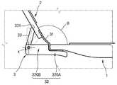
도 5를 참조하면, 지지부(32)는 연성 연결부(31)와 제1몸체(1)의 연결을 지지한다. 지지부(32)는 연성 연결부(31)와 제1몸체(1)의 일부를 지지하는 제1지지영역(320A)을 포함한다. 제1지지영역(320A)은 제1몸체(1)의 일부의 형상에 대응되는 형상을 가질 수 있다. 예를 들어, 제1지지영역(320A)은 제1몸체(1)의 일부가 지지되도록 단차 구조를 가질 수 있다.Referring to FIG. 5, the
지지부(32)는 제2몸체(2)를 제1몸체(1)에 대하여 소정 각도(θ)로 지지하는 제2지지영역(320B)을 포함한다. 제2지지영역(320B)은 연성 연결부(31)가 제2상태(31-2)에서 유지되도록 제2몸체(2)를 거치시키는 거치부(33)를 더 포함할 수 있다.The
거치부(33)는 제2몸체(2)가 제1몸체(1)에 대하여 둔각 범위 내에서 거치되도록 각도 조절이 가능하다. 예를 들어, 도면에서 점선으로 표시한 것처럼 거치부(33)는 회전축(x)을 기준으로 다양한 각도로 회전될 수 있다. 거치부(33)의 단부가 제2몸체(2)를 접촉 지지함으로써 제2몸체(2)를 제1몸체(1)에 대하여 소정의 각도로 거치시킬 수 있다. 거치부(33)의 단부는 제2몸체(2)가 소정의 각도에서 접촉 면적이 최대가 되도록 경사면(331)을 가질 수 있다. 여기서, 제2몸체(2)의 각도는 둔각 범위 내에서 필요에 따라 결정될 수 있으며, 예를 들어 105도, 120도 등일 수 있다.Mounting
한편, 거치부(33)는 도 6과 같이 단수 개로서 지지부의 적어도 일부에 형성될 수 있다. 그러나, 거치부(33)는 이에 한정되지 않으며, 필요에 따라 복수 개가 형성될 수 있다.On the other hand, the mounting
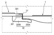
도 7은 본 발명의 실시예에 따른 모바일 기기의 사용 상태의 일 예를 나타낸 측면도이다. 도 8은 도 7의 일부를 확대 도시한 도면이다. 도 7 및 도 8을 참조하면, 모바일 기기는 사용 상태의 일 예로서 제1몸체(1)와 제2몸체(2) 사이의 각도가 평각을 가지도록 펼쳐질 수 있다. 여기서, 제1몸체(1)와 제2몸체(2) 사이의 각도는 제1 몸체(1)의 연장선과 제2몸체(2)의 연장선이 이루는 각도를 의미한다.7 is a side view illustrating an example of a use state of a mobile device according to an embodiment of the present invention. 8 is an enlarged view of a portion of FIG. 7. Referring to FIGS. 7 and 8, the mobile device may be unfolded such that an angle between the
연성 연결부(31)는 제1몸체(1)와 제2몸체(2)를 연결하며, 지지부(32)의 제2지지영역(320B)이 제2몸체(2)의 일부를 지지한다. 제1몸체(1)와 제2몸체(2) 사이의 각도가 평각을 유지하도록 지지부(32)와 제2몸체(2) 사이에 자기력이 작용할 수 있다. 이를 위한 예로서, 지지부(32)의 제2지지영역(320B)에 제1마그넷(321)이 형성되고, 제2몸체(2)의 제1마그넷(321)에 대응하는 영역에 제1마그넷(321)과 반대극성의 제2마그넷(221)이 형성될 수 있다. 이를 통해, 제1몸체(1)와 제2몸체(2)가 평각으로 배치될 때, 제1마그넷(321)과 제2마그넷(221) 사이에 전기적 인력이 작용하여 제1몸체(1)가 지지부(32)에 고정 지지될 수 있다.The
상술한 실시예에서는 자기력을 이용하여 제1몸체(1)가 지지부(32)에 고정 지지된 예를 중심으로 설명하였으나, 제1몸체(1)와 지지부(32)의 고정 구조는 반드시 이에 한정되지 않으며, 후크 결합 등 기계적인 구조에 의해 고정될 수도 있다.In the above-described embodiment, the
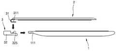
도 9는 도 1에 개시된 모바일 기기에서 힌지 모듈(3)이 제1몸체(1)로부터 탈거된 상태를 나타낸 것이며, 도 10은 도 9에 개시된 지지부(32)와 제1몸체(1)를 하부에서 바라본 배면 사시도이다.FIG. 9 illustrates a state in which the
도 9를 참조하면, 힌지 모듈(3)의 연성 연결부(31)은 제2몸체(2)에 고정 연결될 수 있다. 연성 연결부(31)와 제2몸체(2)의 고정 연결의 예로서, 연성 연결부(31)의 일부를 제2몸체(2)에 접착 고정할 수 있다. 접착 고정 방식으로서, 고주파 융착이 이용될 수 있다.9, the
힌지 모듈(3)의 지지부(32)는 제1몸체(1)와 탈착 가능하게 연결될 수 있다. 탈착 가능하게 연결된 예로서, 암수 결합이 이용될 수 있다. 암수 결합을 위해 지지부(32)에는 돌출 형성된 돌기(325)가 형성되며, 제1몸체(1)에는 돌기(325)가 삽입될 수 있는 오목홈(111)이 형성된다. 연성 연결부(31)는 돌기(325)가 통과할 수 있는 관통공(311)이 형성된다. 돌기(325)는 관통공(311)을 관통하여 오목홈(111)에 삽입됨으로써, 지지부(32)는 연성 연결부(31)가 제1몸체(1)에 연결되는 것을 지지한다. 돌기(325)는 외력의 크기에 따라 탄성 변형됨으로써, 외력이 소정 크기 이상일 때 수축하여 오목홈(111)으로부터 돌기(325)가 이탈되고, 그로 인해 제1몸체(1)로부터 힌지 모듈(3)이 탈거될 수 있다. 그러나, 탈착 가능한 결합을 위한 구조는 이러한 기구적인 구조에 한정되지 않으며, 자력을 이용할 수도 있다.The
한편, 도 10을 참조하면, 지지부(32)는 배터리(322)가 내부에 삽입될 수 있다. 배터리(322)가 삽입된 지지부(32)를 제1몸체(1)에 연결시킴으로써, 제1몸체(1)에 전원을 제공하거나, 전원을 보충할 수 있다. 지지부(32)에는 배터리(322)를 외부로부터 충전하기 위한 충전 단자(323)가 마련될 수 있다. 배터리(322)의 충전 여부를 알기 쉽도록, 지지부(32)는 충전 여부에 따라 점등되는 충전 표시부(324)가 마련될 수 있다.Meanwhile, referring to FIG. 10, the
본 발명은 도면에 도시된 실시예를 참고로 하여 설명되었으나, 이는 예시적인 것에 불과하다. 예를 들어, 상술한 실시예에서는 제1몸체(1)와 제2몸체(2)가 각각 터치스크린 패널인 듀얼 스크린 방식의 태블릿 컴퓨터를 예로 들어 설명하였으나, 이에 한정되지 않으며, 제1몸체(1)는 키보드를 포함하는 조작유닛이며, 제2몸체(2)는 디스플레이 유닛인 노트북 컴퓨터일 수 있다. 또한, 본 발명의 도면에서는 연성 연결부(31)가 제2몸체(2)의 표면에 고정된 것으로 표현되었으나, 이는 설명의 편의를 위한 것일 뿐이므로 제2몸체(2)에 대한 연성 연결부(31)의 연결은 이에 한정되지 아니한다. 예를 들어, 연성 연결부(31)는 제2몸체(2)의 내부에 삽입될 수도 있다. 더불어, 당해 기술이 속하는 분야에서 통상의 지식을 가진 자라면 이로부터 다양한 변형 및 균등한 타 실시예가 가능하다는 점을 이해할 것이다. 따라서, 본 발명의 진정한 기술적 보호범위는 아래의 특허청구범위에 의해서 정하여져야 할 것이다.Although the present invention has been described with reference to the embodiment shown in the drawings, this is merely illustrative. For example, in the above-described embodiment, the
1 : 제1몸체11 : 제1 디스플레이 패널
111 : 오목홈2 : 제2몸체
21 : 제2 디스플레이 패널221 : 제2마그넷
3 : 힌지 모듈31 : 연성 연결부
311 : 관통공32 : 지지부
321 : 제1마그넷322 : 배터리
323 : 충전 단자324 : 충전 표시부
325 : 돌기33 : 거치부
331 : 경사면1: first body 11: first display panel
111: recessed groove 2: the second body
21: second display panel 221: second magnet
3: hinge module 31: flexible connection
311 through
321: first magnet 322: battery
323: charging terminal 324: charging display
325: protrusion 33: mounting portion
331: slope
Claims (16)
Translated fromKorean제2몸체; 및
상기 제1몸체와 상기 제2몸체를 회동 가능하도록 연결하는 힌지 모듈;을 포함하며,
상기 힌지 모듈은,
상기 제1몸체와 상기 제2몸체를 회동 가능하도록 연결하며, 연성 재질을 가지는 연성 연결부와,
상기 제1몸체에 대한 상기 연성 연결부의 연결을 지지하며, 상기 제2몸체를 상기 제1몸체에 대하여 소정 각도로 지지하는 지지부를 포함하는 모바일 기기.First body;
Second body; And
And a hinge module connecting the first body and the second body to be rotatable.
The hinge module,
A flexible connection part connecting the first body and the second body to be rotatable and having a soft material;
And a support part supporting a connection of the flexible connection part to the first body and supporting the second body at a predetermined angle with respect to the first body.
상기 연성 연결부는,
상기 제1몸체가 상기 제2몸체에 의해 폐쇄되도록 접히는 제1상태와,
상기 제1몸체가 상기 제2몸체에 의해 개방되도록 펼쳐지는 제2상태를 가지는 모바일 기기.The method of claim 1,
The flexible connection portion,
A first state in which the first body is folded to be closed by the second body,
A mobile device having a second state in which the first body is opened to be opened by the second body.
상기 지지부는,
상기 연성 연결부가 제2상태에서 유지되도록 상기 제2몸체를 거치시키는 거치부를 더 포함하는 모바일 기기.The method of claim 2,
The support portion,
The mobile device further comprises a mounting portion for mounting the second body to maintain the flexible connection in the second state.
상기 거치부는 상기 제2몸체가 상기 제1몸체에 대하여 둔각 범위 내에서 거치되도록 각도 조절이 가능한 모바일 기기.The method of claim 3,
The mounting portion is a mobile device capable of adjusting the angle so that the second body is mounted in an obtuse angle range with respect to the first body.
상기 거치부의 단부는 상기 제2 몸체와의 접촉 면적이 증가되도록 경사면을 가지는 모바일 기기.The method of claim 4, wherein
The end of the mounting portion has a mobile device having an inclined surface to increase the contact area with the second body.
상기 제1몸체에 대한 상기 제2몸체의 각도가 평각을 유지하도록 상기 지지부와 상기 제2몸체 사이에 자기력이 작용하는 모바일 기기.The method of claim 1,
And a magnetic force acting between the support and the second body such that the angle of the second body relative to the first body maintains a flat angle.
상기 힌지 모듈은 상기 제1몸체와 탈착 가능하게 결합되는 모바일 기기.The method of claim 1,
The hinge module is detachably coupled to the first body.
상기 연성 연결부는 상기 제2몸체와 고정 연결된 모바일 기기.The method of claim 1,
The flexible connection unit is a mobile device fixedly connected to the second body.
상기 연성 연결부는 상기 제1몸체와 상기 제2몸체를 전기적으로 연결하도록 내부에 연성 인쇄회로기판(FPCB)이 삽입된 모바일 기기.The method of claim 1,
The flexible connection unit is a mobile device having a flexible printed circuit board (FPCB) inserted therein to electrically connect the first body and the second body.
상기 제1몸체는 휴대형 컴퓨터의 본체이며,
상기 제2몸체는 상기 본체와 연결되어 화상을 표시하는 디스플레이부를 구비하는 모바일 기기.The method of claim 1,
The first body is the body of the portable computer,
The second body is connected to the main body and a mobile device having a display unit for displaying an image.
상기 제1몸체의 두께가 상기 제2몸체의 두께보다 두꺼운 모바일 기기.The method of claim 10,
The mobile device is thicker than the thickness of the second body of the first body.
상기 제1몸체는 제1 디스플레이 패널을 포함하며,
상기 제2몸체는 제2 디스플레이 패널을 포함하며,
상기 제1 디스플레이 패널, 상기 제2 디스플레이 패널 중 적어도 하나는 터치 스크린 패널인 모바일 기기.The method of claim 11,
The first body includes a first display panel,
The second body includes a second display panel,
At least one of the first display panel and the second display panel is a touch screen panel.
상기 지지부는 내부에 배터리가 삽입되는 모바일 기기.The method of claim 1,
The support unit is a mobile device is inserted into the battery.
상기 지지부는 외부로부터 충전이 가능하도록 충전 단자가 마련된 모바일 기기.The method of claim 13,
The support unit is a mobile device provided with a charging terminal to be charged from the outside.
상기 지지부는 충전 여부에 따라 점등되는 충전 표시부가 마련된 모바일 기기.The method of claim 14,
The support unit is provided with a charging display unit that lights up according to whether the charge.
상기 제1몸체와 상기 제2몸체를 회동 가능하도록 연결하며, 연성 재질을 가지는 연성 연결부; 및
상기 제1몸체에 대한 상기 연성 연결부의 연결을 지지하며, 상기 제2몸체를 상기 제1몸체에 대하여 소정 각도로 지지하는 지지부;를 포함하는 모바일 기기의 힌지 모듈.A hinge module for rotatably connecting the first body and the second body,
A flexible connection part connecting the first body and the second body to be rotatable and having a soft material; And
And a support part supporting a connection of the flexible connection part to the first body and supporting the second body at a predetermined angle with respect to the first body.
Priority Applications (1)
| Application Number | Priority Date | Filing Date | Title |
|---|---|---|---|
| KR1020130053391AKR102053902B1 (en) | 2013-05-10 | 2013-05-10 | Moblie apparatus and hinge module used therein |
Applications Claiming Priority (1)
| Application Number | Priority Date | Filing Date | Title |
|---|---|---|---|
| KR1020130053391AKR102053902B1 (en) | 2013-05-10 | 2013-05-10 | Moblie apparatus and hinge module used therein |
Publications (2)
| Publication Number | Publication Date |
|---|---|
| KR20140133338A KR20140133338A (en) | 2014-11-19 |
| KR102053902B1true KR102053902B1 (en) | 2019-12-09 |
Family
ID=52454034
Family Applications (1)
| Application Number | Title | Priority Date | Filing Date |
|---|---|---|---|
| KR1020130053391AExpired - Fee RelatedKR102053902B1 (en) | 2013-05-10 | 2013-05-10 | Moblie apparatus and hinge module used therein |
Country Status (1)
| Country | Link |
|---|---|
| KR (1) | KR102053902B1 (en) |
Families Citing this family (3)
| Publication number | Priority date | Publication date | Assignee | Title |
|---|---|---|---|---|
| KR101896258B1 (en)* | 2016-09-21 | 2018-09-07 | 엘지전자 주식회사 | Display Appratus |
| CN112667031A (en)* | 2020-12-31 | 2021-04-16 | 联想(北京)有限公司 | Input device and processing system |
| CN116343600A (en)* | 2023-02-28 | 2023-06-27 | 大连理工大学 | A foldable and hidden split-screen display |
Family Cites Families (2)
| Publication number | Priority date | Publication date | Assignee | Title |
|---|---|---|---|---|
| KR100730717B1 (en)* | 2005-05-10 | 2007-06-21 | 삼성전자주식회사 | Portable computer with detachable display |
| KR101841570B1 (en)* | 2010-11-18 | 2018-03-26 | 삼성전자 주식회사 | Dual display folder type terminal |
- 2013
- 2013-05-10KRKR1020130053391Apatent/KR102053902B1/ennot_activeExpired - Fee Related
Also Published As
| Publication number | Publication date |
|---|---|
| KR20140133338A (en) | 2014-11-19 |
Similar Documents
| Publication | Publication Date | Title |
|---|---|---|
| US10503215B1 (en) | Multi-form factor information handling system (IHS) with attachable keyboard | |
| KR101641229B1 (en) | Module for expanding function of electronic device and mobile device having the same | |
| CN209765371U (en) | Information processing apparatus | |
| KR101917683B1 (en) | Mobile device | |
| AU2014201369B2 (en) | Docking apparatus of electronic apparatus | |
| US8995116B2 (en) | Docking station and electronic apparatus using the same | |
| US8306575B2 (en) | Electronic device with configurable displays | |
| JP4203476B2 (en) | Portable information device | |
| CN108604109B (en) | Electronic equipment with prop-up function | |
| KR102468709B1 (en) | Key module and mobile terminal having the same, and method for assembling the key module | |
| EP2369439A2 (en) | Portable electronic apparatus | |
| US9086846B2 (en) | Mobile terminal | |
| US20200081227A1 (en) | Electronic device with deployable and retractable camera assembly | |
| KR20070092042A (en) | Holding Case for Information Processing Equipment | |
| US9179567B2 (en) | Electronic device | |
| KR20150125374A (en) | Mobile terminal | |
| KR102053902B1 (en) | Moblie apparatus and hinge module used therein | |
| CN116868147A (en) | Coupling circuits between flexible electrical components for foldable devices | |
| JP2014107714A (en) | Portable terminal device | |
| US9807483B1 (en) | Mobile device case with foldable speaker system | |
| KR20100097882A (en) | Notebook computer | |
| CN212112279U (en) | Computer split screen device | |
| CN213072789U (en) | Casing and electronic equipment thereof | |
| KR102639610B1 (en) | Mobile terminal, electronic device equipped with mobile terminal, and method of controlling the electronic device | |
| KR101575256B1 (en) | Portable monitor having internal battery |
Legal Events
| Date | Code | Title | Description |
|---|---|---|---|
| PA0109 | Patent application | St.27 status event code:A-0-1-A10-A12-nap-PA0109 | |
| PG1501 | Laying open of application | St.27 status event code:A-1-1-Q10-Q12-nap-PG1501 | |
| A201 | Request for examination | ||
| PA0201 | Request for examination | St.27 status event code:A-1-2-D10-D11-exm-PA0201 | |
| E902 | Notification of reason for refusal | ||
| PE0902 | Notice of grounds for rejection | St.27 status event code:A-1-2-D10-D21-exm-PE0902 | |
| P11-X000 | Amendment of application requested | St.27 status event code:A-2-2-P10-P11-nap-X000 | |
| P13-X000 | Application amended | St.27 status event code:A-2-2-P10-P13-nap-X000 | |
| E701 | Decision to grant or registration of patent right | ||
| PE0701 | Decision of registration | St.27 status event code:A-1-2-D10-D22-exm-PE0701 | |
| GRNT | Written decision to grant | ||
| PR0701 | Registration of establishment | St.27 status event code:A-2-4-F10-F11-exm-PR0701 | |
| PR1002 | Payment of registration fee | St.27 status event code:A-2-2-U10-U11-oth-PR1002 Fee payment year number:1 | |
| PG1601 | Publication of registration | St.27 status event code:A-4-4-Q10-Q13-nap-PG1601 | |
| PC1903 | Unpaid annual fee | St.27 status event code:A-4-4-U10-U13-oth-PC1903 Not in force date:20221204 Payment event data comment text:Termination Category : DEFAULT_OF_REGISTRATION_FEE | |
| PC1903 | Unpaid annual fee | St.27 status event code:N-4-6-H10-H13-oth-PC1903 Ip right cessation event data comment text:Termination Category : DEFAULT_OF_REGISTRATION_FEE Not in force date:20221204 |