KR102052714B1 - Aerosol generating system - Google Patents
Aerosol generating systemDownload PDFInfo
- Publication number
- KR102052714B1 KR102052714B1KR1020190017391AKR20190017391AKR102052714B1KR 102052714 B1KR102052714 B1KR 102052714B1KR 1020190017391 AKR1020190017391 AKR 1020190017391AKR 20190017391 AKR20190017391 AKR 20190017391AKR 102052714 B1KR102052714 B1KR 102052714B1
- Authority
- KR
- South Korea
- Prior art keywords
- holder
- cradle
- heater
- cigarette
- state
- Prior art date
- Legal status (The legal status is an assumption and is not a legal conclusion. Google has not performed a legal analysis and makes no representation as to the accuracy of the status listed.)
- Active
Links
- 239000000443aerosolSubstances0.000titleclaimsabstractdescription71
- 235000019504cigarettesNutrition0.000claimsabstractdescription112
- 238000010438heat treatmentMethods0.000claimsabstractdescription35
- 230000000391smoking effectEffects0.000claimsdescription83
- 238000012544monitoring processMethods0.000claims1
- 235000002637Nicotiana tabacumNutrition0.000description67
- 241000208125NicotianaSpecies0.000description65
- 238000001816coolingMethods0.000description48
- 238000000034methodMethods0.000description47
- 239000000463materialSubstances0.000description28
- 230000006870functionEffects0.000description26
- 230000008569processEffects0.000description23
- 238000010586diagramMethods0.000description19
- 238000004140cleaningMethods0.000description15
- 239000000835fiberSubstances0.000description14
- 239000007788liquidSubstances0.000description12
- 239000004626polylactic acidSubstances0.000description11
- 229920000747poly(lactic acid)Polymers0.000description10
- DNIAPMSPPWPWGF-UHFFFAOYSA-NPropylene glycolChemical compoundCC(O)CODNIAPMSPPWPWGF-UHFFFAOYSA-N0.000description9
- 239000002775capsuleSubstances0.000description9
- PEDCQBHIVMGVHV-UHFFFAOYSA-NGlycerineChemical compoundOCC(O)COPEDCQBHIVMGVHV-UHFFFAOYSA-N0.000description8
- 239000003205fragranceSubstances0.000description8
- 230000000694effectsEffects0.000description7
- 239000000796flavoring agentSubstances0.000description6
- 239000000779smokeSubstances0.000description6
- 239000000126substanceSubstances0.000description6
- 239000008187granular materialSubstances0.000description5
- 238000004519manufacturing processMethods0.000description5
- 238000005520cutting processMethods0.000description4
- 235000019634flavorsNutrition0.000description4
- 235000011187glycerolNutrition0.000description4
- 230000020169heat generationEffects0.000description4
- 230000000977initiatory effectEffects0.000description4
- 238000003780insertionMethods0.000description4
- 230000037431insertionEffects0.000description4
- 239000011148porous materialSubstances0.000description4
- 239000002002slurrySubstances0.000description4
- XLYOFNOQVPJJNP-UHFFFAOYSA-NwaterSubstancesOXLYOFNOQVPJJNP-UHFFFAOYSA-N0.000description4
- NOOLISFMXDJSKH-UTLUCORTSA-N(+)-NeomentholChemical compoundCC(C)[C@@H]1CC[C@@H](C)C[C@@H]1ONOOLISFMXDJSKH-UTLUCORTSA-N0.000description3
- 244000223760Cinnamomum zeylanicumSpecies0.000description3
- NOOLISFMXDJSKH-UHFFFAOYSA-NDL-mentholNatural productsCC(C)C1CCC(C)CC1ONOOLISFMXDJSKH-UHFFFAOYSA-N0.000description3
- LYCAIKOWRPUZTN-UHFFFAOYSA-NEthylene glycolChemical compoundOCCOLYCAIKOWRPUZTN-UHFFFAOYSA-N0.000description3
- 239000000654additiveSubstances0.000description3
- 229920002301cellulose acetatePolymers0.000description3
- 230000008859changeEffects0.000description3
- 235000017803cinnamonNutrition0.000description3
- 239000011248coating agentSubstances0.000description3
- 238000000576coating methodMethods0.000description3
- 230000008878couplingEffects0.000description3
- 238000010168coupling processMethods0.000description3
- 238000005859coupling reactionMethods0.000description3
- 238000001514detection methodMethods0.000description3
- MTHSVFCYNBDYFN-UHFFFAOYSA-Ndiethylene glycolChemical compoundOCCOCCOMTHSVFCYNBDYFN-UHFFFAOYSA-N0.000description3
- 230000001965increasing effectEffects0.000description3
- 229940041616mentholDrugs0.000description3
- 239000003921oilSubstances0.000description3
- 235000019198oilsNutrition0.000description3
- 239000004014plasticizerSubstances0.000description3
- 239000000052vinegarSubstances0.000description3
- 235000021419vinegarNutrition0.000description3
- 238000009941weavingMethods0.000description3
- 229920002907Guar gumPolymers0.000description2
- 244000061176Nicotiana tabacumSpecies0.000description2
- 239000011230binding agentSubstances0.000description2
- 229910010293ceramic materialInorganic materials0.000description2
- 239000003610charcoalSubstances0.000description2
- 239000004020conductorSubstances0.000description2
- 230000001186cumulative effectEffects0.000description2
- 238000001125extrusionMethods0.000description2
- 235000013355food flavoring agentNutrition0.000description2
- 239000000665guar gumSubstances0.000description2
- 235000010417guar gumNutrition0.000description2
- 229960002154guar gumDrugs0.000description2
- 230000007246mechanismEffects0.000description2
- 229910052751metalInorganic materials0.000description2
- 239000002184metalSubstances0.000description2
- 230000003647oxidationEffects0.000description2
- 238000007254oxidation reactionMethods0.000description2
- 239000002994raw materialSubstances0.000description2
- 238000000926separation methodMethods0.000description2
- 229910052710siliconInorganic materials0.000description2
- 239000010703siliconSubstances0.000description2
- 238000003860storageMethods0.000description2
- 239000000758substrateSubstances0.000description2
- 230000000007visual effectEffects0.000description2
- 239000000080wetting agentSubstances0.000description2
- ALSTYHKOOCGGFT-KTKRTIGZSA-N(9Z)-octadecen-1-olChemical compoundCCCCCCCC\C=C/CCCCCCCCOALSTYHKOOCGGFT-KTKRTIGZSA-N0.000description1
- IXPNQXFRVYWDDI-UHFFFAOYSA-N1-methyl-2,4-dioxo-1,3-diazinane-5-carboximidamideChemical compoundCN1CC(C(N)=N)C(=O)NC1=OIXPNQXFRVYWDDI-UHFFFAOYSA-N0.000description1
- 229920001817AgarPolymers0.000description1
- 240000007087Apium graveolensSpecies0.000description1
- 235000015849Apium graveolens Dulce GroupNutrition0.000description1
- 235000010591AppioNutrition0.000description1
- UXVMQQNJUSDDNG-UHFFFAOYSA-LCalcium chlorideChemical group[Cl-].[Cl-].[Ca+2]UXVMQQNJUSDDNG-UHFFFAOYSA-L0.000description1
- 240000007436Cananga odorataSpecies0.000description1
- OKTJSMMVPCPJKN-UHFFFAOYSA-NCarbonChemical compound[C]OKTJSMMVPCPJKN-UHFFFAOYSA-N0.000description1
- 229920002134Carboxymethyl cellulosePolymers0.000description1
- 240000000467Carum carviSpecies0.000description1
- 235000005747Carum carviNutrition0.000description1
- 229920003043Cellulose fiberPolymers0.000description1
- 240000003538Chamaemelum nobileSpecies0.000description1
- 235000007866Chamaemelum nobileNutrition0.000description1
- 240000007154Coffea arabicaSpecies0.000description1
- 244000018436Coriandrum sativumSpecies0.000description1
- 235000002787Coriandrum sativumNutrition0.000description1
- FBPFZTCFMRRESA-FSIIMWSLSA-ND-GlucitolNatural productsOC[C@H](O)[C@H](O)[C@@H](O)[C@H](O)COFBPFZTCFMRRESA-FSIIMWSLSA-N0.000description1
- 240000002943Elettaria cardamomumSpecies0.000description1
- 241000196324EmbryophytaSpecies0.000description1
- 108010010803GelatinProteins0.000description1
- 241000208152GeraniumSpecies0.000description1
- 240000004670Glycyrrhiza echinataSpecies0.000description1
- 235000001453Glycyrrhiza echinataNutrition0.000description1
- 235000006200Glycyrrhiza glabraNutrition0.000description1
- 235000017382Glycyrrhiza lepidotaNutrition0.000description1
- 235000010254Jasminum officinaleNutrition0.000description1
- 240000005385Jasminum sambacSpecies0.000description1
- 244000255365KaskarillabaumSpecies0.000description1
- 244000178870Lavandula angustifoliaSpecies0.000description1
- 235000010663Lavandula angustifoliaNutrition0.000description1
- 235000019501Lemon oilNutrition0.000description1
- 229910012851LiCoO 2Inorganic materials0.000description1
- 229910010707LiFePO 4Inorganic materials0.000description1
- WHXSMMKQMYFTQS-UHFFFAOYSA-NLithiumChemical compound[Li]WHXSMMKQMYFTQS-UHFFFAOYSA-N0.000description1
- HBBGRARXTFLTSG-UHFFFAOYSA-NLithium ionChemical compound[Li+]HBBGRARXTFLTSG-UHFFFAOYSA-N0.000description1
- 235000007232Matricaria chamomillaNutrition0.000description1
- 235000006679Mentha X verticillataNutrition0.000description1
- 235000014749Mentha crispaNutrition0.000description1
- 244000078639Mentha spicataSpecies0.000description1
- 235000002899Mentha suaveolensNutrition0.000description1
- 235000001636Mentha x rotundifoliaNutrition0.000description1
- 244000179970Monarda didymaSpecies0.000description1
- 235000010672Monarda didymaNutrition0.000description1
- 235000019502Orange oilNutrition0.000description1
- 240000000513Santalum albumSpecies0.000description1
- 235000008632Santalum albumNutrition0.000description1
- 229930006000SucroseNatural products0.000description1
- CZMRCDWAGMRECN-UGDNZRGBSA-NSucroseChemical compoundO[C@H]1[C@H](O)[C@@H](CO)O[C@@]1(CO)O[C@@H]1[C@H](O)[C@@H](O)[C@H](O)[C@@H](CO)O1CZMRCDWAGMRECN-UGDNZRGBSA-N0.000description1
- 235000009470Theobroma cacaoNutrition0.000description1
- 244000299461Theobroma cacaoSpecies0.000description1
- RTAQQCXQSZGOHL-UHFFFAOYSA-NTitaniumChemical compound[Ti]RTAQQCXQSZGOHL-UHFFFAOYSA-N0.000description1
- 244000250129Trigonella foenum graecumSpecies0.000description1
- 235000001484Trigonella foenum graecumNutrition0.000description1
- 244000290333Vanilla fragransSpecies0.000description1
- 235000009499Vanilla fragransNutrition0.000description1
- 235000012036Vanilla tahitensisNutrition0.000description1
- 244000273928Zingiber officinaleSpecies0.000description1
- 235000006886Zingiber officinaleNutrition0.000description1
- 230000001154acute effectEffects0.000description1
- 230000000996additive effectEffects0.000description1
- 239000002671adjuvantSubstances0.000description1
- 239000008272agarSubstances0.000description1
- 229940023476agarDrugs0.000description1
- 235000010419agarNutrition0.000description1
- 229910052782aluminiumInorganic materials0.000description1
- XAGFODPZIPBFFR-UHFFFAOYSA-NaluminiumChemical compound[Al]XAGFODPZIPBFFR-UHFFFAOYSA-N0.000description1
- 238000000889atomisationMethods0.000description1
- WHGYBXFWUBPSRW-FOUAGVGXSA-Nbeta-cyclodextrinChemical compoundOC[C@H]([C@H]([C@@H]([C@H]1O)O)O[C@H]2O[C@@H]([C@@H](O[C@H]3O[C@H](CO)[C@H]([C@@H]([C@H]3O)O)O[C@H]3O[C@H](CO)[C@H]([C@@H]([C@H]3O)O)O[C@H]3O[C@H](CO)[C@H]([C@@H]([C@H]3O)O)O[C@H]3O[C@H](CO)[C@H]([C@@H]([C@H]3O)O)O3)[C@H](O)[C@H]2O)CO)O[C@@H]1O[C@H]1[C@H](O)[C@@H](O)[C@@H]3O[C@@H]1COWHGYBXFWUBPSRW-FOUAGVGXSA-N0.000description1
- 230000005540biological transmissionEffects0.000description1
- 229910052799carbonInorganic materials0.000description1
- 235000005300cardamomoNutrition0.000description1
- 235000010418carrageenanNutrition0.000description1
- 239000000679carrageenanSubstances0.000description1
- 229920001525carrageenanPolymers0.000description1
- 229940113118carrageenanDrugs0.000description1
- 239000001913celluloseSubstances0.000description1
- 229920002678cellulosePolymers0.000description1
- 235000016213coffeeNutrition0.000description1
- 235000013353coffee beverageNutrition0.000description1
- 235000020057cognacNutrition0.000description1
- 239000003086colorantSubstances0.000description1
- 238000002485combustion reactionMethods0.000description1
- 238000004891communicationMethods0.000description1
- 239000002131composite materialSubstances0.000description1
- 230000003247decreasing effectEffects0.000description1
- 229920006237degradable polymerPolymers0.000description1
- SZXQTJUDPRGNJN-UHFFFAOYSA-Ndipropylene glycolChemical compoundOCCCOCCCOSZXQTJUDPRGNJN-UHFFFAOYSA-N0.000description1
- 238000007599dischargingMethods0.000description1
- 238000001035dryingMethods0.000description1
- 238000010292electrical insulationMethods0.000description1
- 239000003995emulsifying agentSubstances0.000description1
- 238000005516engineering processMethods0.000description1
- 230000002708enhancing effectEffects0.000description1
- -1etc.)Substances0.000description1
- 239000000945fillerSubstances0.000description1
- 238000011049fillingMethods0.000description1
- 235000021433fructose syrupNutrition0.000description1
- 239000008273gelatinSubstances0.000description1
- 229920000159gelatinPolymers0.000description1
- 229940014259gelatinDrugs0.000description1
- 235000019322gelatineNutrition0.000description1
- 235000011852gelatine dessertsNutrition0.000description1
- 235000008397gingerNutrition0.000description1
- 235000012907honeyNutrition0.000description1
- 239000003906humectantSubstances0.000description1
- 239000001102lavandula veraSubstances0.000description1
- 235000018219lavenderNutrition0.000description1
- 239000010501lemon oilSubstances0.000description1
- 229940010454licoriceDrugs0.000description1
- 229910052744lithiumInorganic materials0.000description1
- 229910000625lithium cobalt oxideInorganic materials0.000description1
- 229910001416lithium ionInorganic materials0.000description1
- GELKBWJHTRAYNV-UHFFFAOYSA-Klithium iron phosphateChemical compound[Li+].[Fe+2].[O-]P([O-])([O-])=OGELKBWJHTRAYNV-UHFFFAOYSA-K0.000description1
- BFZPBUKRYWOWDV-UHFFFAOYSA-Nlithium;oxido(oxo)cobaltChemical compound[Li+].[O-][Co]=OBFZPBUKRYWOWDV-UHFFFAOYSA-N0.000description1
- 150000004667medium chain fatty acidsChemical class0.000description1
- 229910001092metal group alloyInorganic materials0.000description1
- 239000007769metal materialSubstances0.000description1
- 239000000203mixtureSubstances0.000description1
- 229940055577oleyl alcoholDrugs0.000description1
- XMLQWXUVTXCDDL-UHFFFAOYSA-Noleyl alcoholNatural productsCCCCCCC=CCCCCCCCCCCOXMLQWXUVTXCDDL-UHFFFAOYSA-N0.000description1
- 230000003287optical effectEffects0.000description1
- 239000010502orange oilSubstances0.000description1
- 150000007524organic acidsChemical class0.000description1
- 235000005985organic acidsNutrition0.000description1
- 239000005022packaging materialSubstances0.000description1
- 239000001814pectinSubstances0.000description1
- 235000010987pectinNutrition0.000description1
- 229920001277pectinPolymers0.000description1
- 229960000292pectinDrugs0.000description1
- 239000002304perfumeSubstances0.000description1
- 230000002688persistenceEffects0.000description1
- 230000000704physical effectEffects0.000description1
- 229920001223polyethylene glycolPolymers0.000description1
- 230000002250progressing effectEffects0.000description1
- 235000019719rose oilNutrition0.000description1
- 239000010666rose oilSubstances0.000description1
- 235000002020sageNutrition0.000description1
- 235000010413sodium alginateNutrition0.000description1
- 239000000661sodium alginateSubstances0.000description1
- 229940005550sodium alginateDrugs0.000description1
- 239000002904solventSubstances0.000description1
- 239000000600sorbitolSubstances0.000description1
- 238000005507sprayingMethods0.000description1
- 239000005720sucroseSubstances0.000description1
- UWHCKJMYHZGTIT-UHFFFAOYSA-Ntetraethylene glycolChemical compoundOCCOCCOCCOCCOUWHCKJMYHZGTIT-UHFFFAOYSA-N0.000description1
- 239000002562thickening agentSubstances0.000description1
- ZIBGPFATKBEMQZ-UHFFFAOYSA-Ntriethylene glycolChemical compoundOCCOCCOCCOZIBGPFATKBEMQZ-UHFFFAOYSA-N0.000description1
- UFTFJSFQGQCHQW-UHFFFAOYSA-NtriforminChemical compoundO=COCC(OC=O)COC=OUFTFJSFQGQCHQW-UHFFFAOYSA-N0.000description1
- 235000001019trigonella foenum-graecumNutrition0.000description1
- 239000011800void materialSubstances0.000description1
- 239000000341volatile oilSubstances0.000description1
- 239000002023woodSubstances0.000description1
- 239000000230xanthan gumSubstances0.000description1
- 235000010493xanthan gumNutrition0.000description1
- 229920001285xanthan gumPolymers0.000description1
- 229940082509xanthan gumDrugs0.000description1
- UHVMMEOXYDMDKI-JKYCWFKZSA-Lzinc;1-(5-cyanopyridin-2-yl)-3-[(1s,2s)-2-(6-fluoro-2-hydroxy-3-propanoylphenyl)cyclopropyl]urea;diacetateChemical compound[Zn+2].CC([O-])=O.CC([O-])=O.CCC(=O)C1=CC=C(F)C([C@H]2[C@H](C2)NC(=O)NC=2N=CC(=CC=2)C#N)=C1OUHVMMEOXYDMDKI-JKYCWFKZSA-L0.000description1
Images


Classifications
- A—HUMAN NECESSITIES
- A24—TOBACCO; CIGARS; CIGARETTES; SIMULATED SMOKING DEVICES; SMOKERS' REQUISITES
- A24F—SMOKERS' REQUISITES; MATCH BOXES; SIMULATED SMOKING DEVICES
- A24F40/00—Electrically operated smoking devices; Component parts thereof; Manufacture thereof; Maintenance or testing thereof; Charging means specially adapted therefor
- A24F40/50—Control or monitoring
- A24F40/53—Monitoring, e.g. fault detection
- A24F47/008—
- A—HUMAN NECESSITIES
- A24—TOBACCO; CIGARS; CIGARETTES; SIMULATED SMOKING DEVICES; SMOKERS' REQUISITES
- A24B—MANUFACTURE OR PREPARATION OF TOBACCO FOR SMOKING OR CHEWING; TOBACCO; SNUFF
- A24B15/00—Chemical features or treatment of tobacco; Tobacco substitutes, e.g. in liquid form
- A24B15/10—Chemical features of tobacco products or tobacco substitutes
- A24B15/16—Chemical features of tobacco products or tobacco substitutes of tobacco substitutes
- A24B15/167—Chemical features of tobacco products or tobacco substitutes of tobacco substitutes in liquid or vaporisable form, e.g. liquid compositions for electronic cigarettes
- A—HUMAN NECESSITIES
- A24—TOBACCO; CIGARS; CIGARETTES; SIMULATED SMOKING DEVICES; SMOKERS' REQUISITES
- A24F—SMOKERS' REQUISITES; MATCH BOXES; SIMULATED SMOKING DEVICES
- A24F40/00—Electrically operated smoking devices; Component parts thereof; Manufacture thereof; Maintenance or testing thereof; Charging means specially adapted therefor
- A24F40/40—Constructional details, e.g. connection of cartridges and battery parts
- A—HUMAN NECESSITIES
- A24—TOBACCO; CIGARS; CIGARETTES; SIMULATED SMOKING DEVICES; SMOKERS' REQUISITES
- A24F—SMOKERS' REQUISITES; MATCH BOXES; SIMULATED SMOKING DEVICES
- A24F40/00—Electrically operated smoking devices; Component parts thereof; Manufacture thereof; Maintenance or testing thereof; Charging means specially adapted therefor
- A24F40/50—Control or monitoring
- A24F40/57—Temperature control
- A—HUMAN NECESSITIES
- A24—TOBACCO; CIGARS; CIGARETTES; SIMULATED SMOKING DEVICES; SMOKERS' REQUISITES
- A24F—SMOKERS' REQUISITES; MATCH BOXES; SIMULATED SMOKING DEVICES
- A24F40/00—Electrically operated smoking devices; Component parts thereof; Manufacture thereof; Maintenance or testing thereof; Charging means specially adapted therefor
- A24F40/85—Maintenance, e.g. cleaning
- A—HUMAN NECESSITIES
- A61—MEDICAL OR VETERINARY SCIENCE; HYGIENE
- A61M—DEVICES FOR INTRODUCING MEDIA INTO, OR ONTO, THE BODY; DEVICES FOR TRANSDUCING BODY MEDIA OR FOR TAKING MEDIA FROM THE BODY; DEVICES FOR PRODUCING OR ENDING SLEEP OR STUPOR
- A61M11/00—Sprayers or atomisers specially adapted for therapeutic purposes
- A61M11/04—Sprayers or atomisers specially adapted for therapeutic purposes operated by the vapour pressure of the liquid to be sprayed or atomised
- A61M11/041—Sprayers or atomisers specially adapted for therapeutic purposes operated by the vapour pressure of the liquid to be sprayed or atomised using heaters
- A61M11/042—Sprayers or atomisers specially adapted for therapeutic purposes operated by the vapour pressure of the liquid to be sprayed or atomised using heaters electrical
- A—HUMAN NECESSITIES
- A61—MEDICAL OR VETERINARY SCIENCE; HYGIENE
- A61M—DEVICES FOR INTRODUCING MEDIA INTO, OR ONTO, THE BODY; DEVICES FOR TRANSDUCING BODY MEDIA OR FOR TAKING MEDIA FROM THE BODY; DEVICES FOR PRODUCING OR ENDING SLEEP OR STUPOR
- A61M15/00—Inhalators
- A61M15/0065—Inhalators with dosage or measuring devices
- A61M15/0068—Indicating or counting the number of dispensed doses or of remaining doses
- A61M15/008—Electronic counters
- A—HUMAN NECESSITIES
- A61—MEDICAL OR VETERINARY SCIENCE; HYGIENE
- A61M—DEVICES FOR INTRODUCING MEDIA INTO, OR ONTO, THE BODY; DEVICES FOR TRANSDUCING BODY MEDIA OR FOR TAKING MEDIA FROM THE BODY; DEVICES FOR PRODUCING OR ENDING SLEEP OR STUPOR
- A61M15/00—Inhalators
- A61M15/06—Inhaling appliances shaped like cigars, cigarettes or pipes
- H—ELECTRICITY
- H05—ELECTRIC TECHNIQUES NOT OTHERWISE PROVIDED FOR
- H05B—ELECTRIC HEATING; ELECTRIC LIGHT SOURCES NOT OTHERWISE PROVIDED FOR; CIRCUIT ARRANGEMENTS FOR ELECTRIC LIGHT SOURCES, IN GENERAL
- H05B1/00—Details of electric heating devices
- H05B1/02—Automatic switching arrangements specially adapted to apparatus ; Control of heating devices
Landscapes
- Health & Medical Sciences (AREA)
- Engineering & Computer Science (AREA)
- Life Sciences & Earth Sciences (AREA)
- General Health & Medical Sciences (AREA)
- Veterinary Medicine (AREA)
- Public Health (AREA)
- Anesthesiology (AREA)
- Biomedical Technology (AREA)
- Heart & Thoracic Surgery (AREA)
- Hematology (AREA)
- Animal Behavior & Ethology (AREA)
- Pulmonology (AREA)
- Bioinformatics & Cheminformatics (AREA)
- Chemical & Material Sciences (AREA)
- Chemical Kinetics & Catalysis (AREA)
- General Chemical & Material Sciences (AREA)
- Biophysics (AREA)
- Secondary Cells (AREA)
- Resistance Heating (AREA)
- Disinfection, Sterilisation Or Deodorisation Of Air (AREA)
- Battery Mounting, Suspending (AREA)
Abstract
Translated fromKoreanDescription
Translated fromKorean에어로졸 생성 시스템에 관한다.It relates to an aerosol generating system.
근래에 궐련을 연소시켜 에어로졸을 생성시키는 방법이 아닌 궐련 내의 에어로졸 생성 물질이 가열됨에 따라 에어로졸이 생성하는 방법에 관한 수요가 증가하고 있다. 이에 따라, 가열식 궐련 또는 가열식 에어로졸 생성 장치에 대한 연구가 활발히 진행되고 있다.Recently, as the aerosol generating material in the cigarette is heated, rather than the method of burning the cigarette to produce an aerosol, there is an increasing demand for a method for producing an aerosol. Accordingly, studies on heated cigarette or heated aerosol generating devices are actively progressing.
에어로졸 생성 시스템을 제공하는데 있다. 또한, 상기 방법을 컴퓨터에서 실행시키기 위한 프로그램을 기록한 컴퓨터로 읽을 수 있는 기록매체를 제공하는 데 있다. 해결하려는 기술적 과제는 상기된 바와 같은 기술적 과제들로 한정되지 않으며, 또 다른 기술적 과제들이 존재할 수 있다.It is to provide an aerosol generating system. In addition, the present invention provides a computer-readable recording medium having recorded thereon a program for executing the method on a computer. The technical problem to be solved is not limited to the above technical problems, and other technical problems may exist.
일 측면에 따르면, 에어로졸 생성 시스템은, 궐련이 삽입된 경우 상기 삽입된 궐련을 가열함으로써 에어로졸을 생성하는 홀더 디바이스; 및 상기 홀더 디바이스를 수용하는 내부 공간이 마련되고, 상기 홀더 디바이스가 상기 내부 공간에 수용된 상태에서 상기 홀더 디바이스에 상기 궐련의 삽입이 가능하도록 상기 내부 공간과 함께 상기 홀더가 틸트(tilt)되는 크래들 디바이스를 포함하고, 상기 홀더 디바이스는 상기 홀더 디바이스가 상기 크래들 디바이스에서 틸트된 제 1 상태 및 상기 홀더 디바이스가 상기 크래들 디바이스로부터 분리된 제 2 상태에서의 흡연 패턴을 누적적으로 모니터링하고, 상기 누적적으로 모니터링된 흡연 패턴이 흡연 제한 조건을 충족하는지 여부를 판단한다.According to one aspect, an aerosol generating system comprises: a holder device for generating an aerosol by heating the inserted cigarette when a cigarette is inserted; And an inner space for accommodating the holder device, the cradle device in which the holder is tilted together with the inner space to enable insertion of the cigarette into the holder device while the holder device is accommodated in the inner space. Wherein the holder device cumulatively monitors a smoking pattern in a first state in which the holder device is tilted in the cradle device and in a second state in which the holder device is separated from the cradle device, It is determined whether the monitored smoking pattern meets smoking restrictions.
또한, 상기 홀더 디바이스는, 상기 제 1 상태에서 흡연이 진행되었다가 뒤이어 상기 제 2 상태에서 상기 흡연이 진행된 경우 상기 제 1 상태에서 모니터링된 흡연 패턴에 상기 제 2 상태에서 모니터링된 흡연 패턴을 누적하고, 상기 누적된 흡연 패턴이 상기 흡연 제한 조건을 충족한 경우 상기 삽입된 궐련의 가열이 중단되도록 상기 홀더 디바이스 내 구비된 히터를 제어한다.Further, the holder device accumulates the smoking pattern monitored in the second state on the smoking pattern monitored in the first state when smoking proceeds in the first state followed by smoking in the second state. The heater provided in the holder device is controlled to stop heating of the inserted cigarette when the accumulated smoking pattern satisfies the smoking restriction condition.
또한, 상기 홀더 디바이스는, 상기 제 2 상태에서 흡연이 진행되었다가 뒤이어 상기 제 1 상태에서 상기 흡연이 진행된 경우 상기 제 2 상태에서 모니터링된 흡연 패턴에 상기 제 1 상태에서 모니터링된 흡연 패턴을 누적하고, 상기 누적된 흡연 패턴이 상기 흡연 제한 조건을 충족한 경우 상기 삽입된 궐련의 가열이 중단되도록 상기 홀더 디바이스 내 구비된 히터를 제어한다.Further, the holder device accumulates the smoking pattern monitored in the first state on the smoking pattern monitored in the second state when smoking proceeds in the second state followed by smoking in the first state. The heater provided in the holder device is controlled to stop heating of the inserted cigarette when the accumulated smoking pattern satisfies the smoking restriction condition.
또한, 상기 흡연 패턴은 상기 삽입된 궐련에 대한 퍼프 횟수를 포함하고, 상기 흡연 제한 조건은 퍼프 제한 횟수를 포함하고, 상기 홀더 디바이스는 상기 제 1 상태 및 상기 제 2 상태에서 누적적으로 모니터링된 퍼프 횟수가 상기 퍼프 제한 횟수에 도달한 경우, 상기 삽입된 궐련의 가열이 중단되도록 상기 홀더 디바이스 내 구비된 히터를 제어한다.In addition, the smoking pattern includes the number of puffs for the inserted cigarette, the smoking restriction condition includes the number of puffs, and the holder device is cumulatively monitored in the first and second states. When the number of times reaches the puff limit number, the heater provided in the holder device is controlled to stop heating of the inserted cigarette.
또한, 상기 흡연 패턴은 상기 홀더의 동작 시간을 포함하고, 상기 흡연 제한 조건은 동작 제한 시간을 포함하고, 상기 홀더 디바이스는 상기 제 1 상태 및 상기 제 2 상태에서 누적적으로 모니터링된 동작 시간이 상기 동작 제한 시간에 도달한 경우, 상기 삽입된 궐련의 가열이 중단되도록 상기 홀더 디바이스 내 구비된 히터를 제어한다.Further, the smoking pattern includes an operating time of the holder, the smoking restriction condition includes an operating time limit, and the holder device is configured to accumulate operating time cumulatively monitored in the first state and the second state. When the operation time limit is reached, the heater provided in the holder device is controlled to stop heating of the inserted cigarette.
다른 측면에 따르면, 에어로졸 생성 시스템에 이용되는 홀더 디바이스는, 궐련이 삽입된 경우 에어로졸 생성을 위해 상기 삽입된 궐련을 가열하는 히터; 상기 삽입된 궐련의 가열을 위하여 상기 히터에 전력을 공급하는 배터리; 및 상기 전력의 공급을 제어함으로써 상기 히터의 온도를 제어하는 제어부를 포함하고, 상기 제어부는 상기 홀더 디바이스를 수용하는 내부 공간이 마련된 크래들 디바이스에서 상기 홀더 디바이스가 상기 내부 공간과 함께 틸트된 제 1 상태 및 상기 홀더 디바이스가 상기 크래들 디바이스로부터 분리된 제 2 상태에서의 흡연 패턴을 누적적으로 모니터링하고, 상기 누적적으로 모니터링된 흡연 패턴이 흡연 제한 조건을 충족하는지 여부를 판단한다.According to another aspect, a holder device for use in an aerosol generating system comprises a heater for heating the inserted cigarette for aerosol generation when the cigarette is inserted; A battery for supplying power to the heater for heating the inserted cigarette; And a control unit controlling a temperature of the heater by controlling the supply of power, wherein the control unit is a first state in which the holder device is tilted together with the internal space in a cradle device having an internal space accommodating the holder device. And the holder device cumulatively monitors a smoking pattern in a second state separated from the cradle device, and determines whether the cumulatively monitored smoking pattern meets a smoking restriction condition.
또한, 상기 제어부는 상기 제 1 상태에서 흡연이 진행되었다가 뒤이어 상기 제 2 상태에서 상기 흡연이 진행된 경우 상기 제 1 상태에서 모니터링된 흡연 패턴에 상기 제 2 상태에서 모니터링된 흡연 패턴을 누적하고, 상기 누적된 흡연 패턴이 상기 흡연 제한 조건을 충족한 경우 상기 삽입된 궐련의 가열이 중단되도록 상기 히터의 온도를 제어한다.The controller may accumulate the smoking pattern monitored in the second state on the smoking pattern monitored in the first state when the smoking proceeds in the first state and then in the second state. The temperature of the heater is controlled such that heating of the inserted cigarette is stopped when a cumulative smoking pattern meets the smoking restriction condition.
또한, 상기 제어부는 상기 제 2 상태에서 흡연이 진행되었다가 뒤이어 상기 제 1 상태에서 상기 흡연이 진행된 경우 상기 제 2 상태에서 모니터링된 흡연 패턴에 상기 제 1 상태에서 모니터링된 흡연 패턴을 누적하고, 상기 누적된 흡연 패턴이 상기 흡연 제한 조건을 충족한 경우 상기 삽입된 궐련의 가열이 중단되도록 상기 히터의 온도를 제어한다..The controller may accumulate the smoking pattern monitored in the first state on the smoking pattern monitored in the second state when the smoking proceeds in the second state and then in the first state. The temperature of the heater is controlled such that heating of the inserted cigarette is stopped when a cumulative smoking pattern meets the smoking restriction condition.
또한, 상기 흡연 패턴은 상기 삽입된 궐련에 대한 퍼프 횟수를 포함하고, 상기 흡연 제한 조건은 퍼프 제한 횟수를 포함하고, 상기 제어부는 상기 제 1 상태 및 상기 제 2 상태에서 누적적으로 모니터링된 퍼프 횟수가 상기 퍼프 제한 횟수에 도달한 경우, 상기 삽입된 궐련의 가열이 중단되도록 상기 히터의 온도를 제어한다.The smoking pattern may include a number of puffs for the inserted cigarette, the smoking restriction condition may include a puff limit, and the controller may accumulate the number of puffs cumulatively monitored in the first state and the second state. When the number of times the puff limit is reached, the temperature of the heater is controlled to stop heating of the inserted cigarette.
또한, 상기 흡연 패턴은 상기 홀더의 동작 시간을 포함하고, 상기 흡연 제한 조건은 동작 제한 시간을 포함하고, 상기 제어부는 상기 제 1 상태 및 상기 제 2 상태에서 누적적으로 모니터링된 동작 시간이 상기 동작 제한 시간에 도달한 경우, 상기 삽입된 궐련의 가열이 중단되도록 상기 히터의 온도를 제어한다.The smoking pattern may include an operation time of the holder, the smoking restriction condition may include an operation time limit, and the controller may further include the operation time that is cumulatively monitored in the first state and the second state. When the time limit is reached, the temperature of the heater is controlled to stop heating of the inserted cigarette.
상기된 바에 따르면, 홀더 디바이스가 크래들 디바이스에 결합되어 틸트된 상태이거나 또는 홀더 디바이스가 크래들 디바이스로부터 분리된 상태 등 어떠한 상태에서도, 홀더 디바이스의 동작을 지속적으로 모니터링할 수 있다.According to the above, the operation of the holder device can be continuously monitored in any state, such as when the holder device is coupled to the cradle device and tilted or when the holder device is separated from the cradle device.
도 1은 에어로졸 생성 장치의 일 예를 도시한 구성도이다.
도 2a 및 도 2b는 홀더의 일 예를 여러 측면에서 도시한 도면들이다.
도 3은 크래들의 일 예를 도시한 구성도이다.
도 4a 및 도 4b는 크래들의 일 예를 여러 측면에서 도시한 도면들이다.
도 5는 홀더가 크래들에 삽입되는 일 예를 도시한 도면이다.
도 6은 홀더가 크래들에 삽입된 상태에서 틸트되는 일 예를 도시한 도면이다.
도 7a 내지 도 7b는 홀더가 크래들에 삽입된 예들을 도시한 도면들이다.
도 8은 홀더 및 크래들이 동작하는 일 예를 설명하기 위한 흐름도이다.
도 9는 홀더가 동작하는 일 예를 설명하기 위한 흐름도이다.
도 10은 크래들이 동작하는 일 예를 설명하기 위한 흐름도이다.
도 11은 홀더에 궐련이 삽입된 일 예를 도시한 도면이다.
도 12a 및 12b는 궐련의 일 예를 도시한 구성도이다.
도 13a 내지 도 13f는 궐련의 냉각 구조물의 예들을 도시한 도면들이다.
도 14는 일 실시예에 따라, 크래들에서 틸트된 홀더를 이용하여 흡연을 하는 동작을 설명하기 위한 도면이다.
도 15는 일 실시예에 따라 홀더가 틸트 및 분리된 경우 퍼프 횟수를 카운팅하는 방법의 흐름도이다.
도 16은 일 실시예에 따라 홀더가 틸트 및 분리된 경우 동작 시간을 카운팅하는 방법의 흐름도이다.
도 17은 일 실시예에 따라 홀더에서 퍼프 횟수를 카운팅하는 방법을 설명하기 위한 도면이다.
도 18은 다른 실시예에 따라 홀더에서 퍼프 횟수를 카운팅하는 방법을 설명하기 위한 도면이다.
도 19는 또 다른 실시예에 따라 홀더에서 퍼프 횟수를 카운팅하는 방법을 설명하기 위한 도면이다.
도 20은 일 실시예에 따라 홀더에서 동작 시간을 카운팅하는 방법을 설명하기 위한 도면이다.1 is a configuration diagram showing an example of an aerosol generating device.
2A and 2B illustrate an example of a holder in various aspects.
3 is a diagram illustrating an example of a cradle.
4A and 4B illustrate an example of the cradle from various aspects.
5 is a diagram illustrating an example in which a holder is inserted into a cradle.
6 is a diagram illustrating an example in which the holder is tilted in a state where the holder is inserted into the cradle.
7A-7B illustrate examples in which a holder is inserted into a cradle.
8 is a flowchart illustrating an example in which the holder and the cradle operate.
9 is a flowchart illustrating an example in which the holder operates.
10 is a flowchart for explaining an example in which the cradle operates.
11 is a diagram illustrating an example in which a cigarette is inserted into a holder.
12A and 12B are diagrams illustrating an example of a cigarette.
13A-13F illustrate examples of a cooling structure of a cigarette.
14 is a view for explaining an operation of smoking using a holder tilted in the cradle according to an embodiment.
15 is a flow chart of a method of counting the number of puffs when the holder is tilted and detached according to one embodiment.
16 is a flowchart of a method of counting operating time when a holder is tilted and detached according to one embodiment.
17 is a diagram for describing a method of counting the number of puffs in a holder, according to an exemplary embodiment.
18 is a diagram for describing a method of counting the number of puffs in a holder according to another exemplary embodiment.
19 is a view for explaining a method of counting the number of puffs in a holder according to another embodiment.
20 is a diagram for describing a method of counting an operation time in a holder, according to an exemplary embodiment.
실시 예들에서 사용되는 용어는 본 발명에서의 기능을 고려하면서 가능한 현재 널리 사용되는 일반적인 용어들을 선택하였으나, 이는 당 분야에 종사하는 기술자의 의도 또는 판례, 새로운 기술의 출현 등에 따라 달라질 수 있다. 또한, 특정한 경우는 출원인이 임의로 선정한 용어도 있으며, 이 경우 해당되는 발명의 설명 부분에서 상세히 그 의미를 기재할 것이다. 따라서 본 발명에서 사용되는 용어는 단순한 용어의 명칭이 아닌, 그 용어가 가지는 의미와 본 발명의 전반에 걸친 내용을 토대로 정의되어야 한다.The terms used in the embodiments have been selected as widely used general terms as possible in consideration of the functions in the present invention, but this may vary according to the intention or precedent of the person skilled in the art, the emergence of new technologies. In addition, in certain cases, there is also a term arbitrarily selected by the applicant, in which case the meaning will be described in detail in the description of the invention. Therefore, the terms used in the present invention should be defined based on the meanings of the terms and the contents throughout the present invention, rather than the names of the simple terms.
명세서 전체에서 어떤 부분이 어떤 구성요소를 “포함”한다고 할 때, 이는 특별히 반대되는 기재가 없는 한 다른 구성요소를 제외하는 것이 아니라 다른 구성요소를 더 포함할 수 있음을 의미한다. 또한, 명세서에 기재된 “…부”, “…모듈” 등의 용어는 적어도 하나의 기능이나 동작을 처리하는 단위를 의미하며, 이는 하드웨어 또는 소프트웨어로 구현되거나 하드웨어와 소프트웨어의 결합으로 구현될 수 있다.When a part of the specification is said to "include" any component, this means that it may further include other components, except to exclude other components unless otherwise stated. In addition, the “…” described in the specification. Wealth ”,“… Module ”means a unit for processing at least one function or operation, which may be implemented in hardware or software, or a combination of hardware and software.
아래에서는 첨부한 도면을 참고하여 본 발명의 실시 예에 대하여 본 발명이 속하는 기술 분야에서 통상의 지식을 가진 자가 용이하게 실시할 수 있도록 상세히 설명한다. 그러나 본 발명은 여러 가지 상이한 형태로 구현될 수 있으며 여기에서 설명하는 실시 예에 한정되지 않는다.Hereinafter, exemplary embodiments of the present invention will be described in detail with reference to the accompanying drawings so that those skilled in the art may easily implement the present invention. As those skilled in the art would realize, the described embodiments may be modified in various different ways, all without departing from the spirit or scope of the present invention.
이하에서는 도면을 참조하여 본 발명의 실시 예들을 상세히 설명한다.Hereinafter, with reference to the drawings will be described embodiments of the present invention;
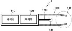
도 1은 에어로졸 생성 장치의 일 예를 도시한 구성도이다.1 is a configuration diagram showing an example of an aerosol generating device.
도 1을 참조하면, 에어로졸 생성 장치(1)(이하, '홀더'라고 함)는 배터리(110), 제어부(120) 및 히터(130)를 포함한다. 또한, 홀더(1)는 케이스(140)에 의하여 형성된 내부 공간을 포함한다. 홀더(1)의 내부 공간에는 궐련이 삽입될 수 있다.Referring to FIG. 1, an aerosol generating device 1 (hereinafter referred to as a holder) includes a
도 1에 도시된 홀더(1)에는 본 실시예와 관련된 구성요소들만이 도시되어 있다. 따라서, 도 1에 도시된 구성요소들 외에 다른 범용적인 구성요소들이 홀더(1)에 더 포함될 수 있음을 본 실시예와 관련된 기술분야에서 통상의 지식을 가진 자라면 이해할 수 있다.The
궐련이 홀더(1)에 삽입되면, 홀더(1)는 히터(130)를 가열한다. 궐련 내의 에어로졸 생성 물질은 가열된 히터(130)에 의하여 온도가 상승하고, 이에 따라 에어로졸이 생성된다. 생성된 에어로졸은 궐련의 필터를 통하여 사용자에게 전달된다. 다만, 궐련이 홀더(1)에 삽입되지 않은 경우에도 홀더(1)는 히터(130)를 가열할 수 있다.When the cigarette is inserted into the
케이스(140)는 홀더(1)에서 분리될 수 있다. 예를 들어, 사용자가 케이스(140)를 시계 방향 또는 반 시계 방향으로 돌림으로써, 케이스(140)는 홀더(1)에서 분리될 수 있다.The
또한, 케이스(140)의 말단(141)이 형성하는 구멍의 직경은 케이스(140)와 히터(130)에 의하여 형성된 공간의 직경에 비하여 작게 제작될 수 있고, 이 경우 홀더(1)에 삽입되는 궐련의 가이드 역할을 수행할 수 있다.In addition, the diameter of the hole formed by the
배터리(110)는 홀더(1)가 동작하는데 이용되는 전력을 공급한다. 예를 들어, 배터리(110)는 히터(130)가 가열될 수 있도록 전력을 공급할 수 있고, 제어부(120)가 동작하는데 필요한 전력을 공급할 수 있다. 또한, 배터리(110)는 홀더(1)에 설치된 디스플레이, 센서, 모터 등이 동작하는데 필요한 전력을 공급할 수 있다.The
배터리(110)는 리튬인산철(LiFePO4) 배터리일 수 있으나, 상술한 예에 한정되지 않는다. 예를 들어, 배터리(110)는 산화 리튬 코발트(LiCoO2) 배터리, 리튬 티탄산염 배터리 등이 해당될 수 있다.The
또한, 배터리(110)는 직경이 10mm이고, 길이가 37mm인 원기둥의 형상일 수 있으나, 이에 한정되지 않는다. 배터리(110)의 용량은 120mAh 이상 일 수 있고, 충전이 가능한 배터리 이거나 일회용 배터리 일 수 있다. 예를 들어, 배터리(110)가 충전이 가능한 경우, 배터리(110)의 충전율(C-rate)은 10C, 방전율(C-rate)는 16C 내지 20C 일 수 있으나, 이에 한정되지 않는다. 또한, 안정적인 사용을 위하여, 배터리(110)는 충/방전이 8000회 진행된 경우에도, 전체 용량의 80% 이상이 확보될 수 있도록 제작될 수 있다.In addition, the
여기에서, 배터리(110)의 완전 충전 및 완전 방전 여부는, 배터리(110)에 저장된 전력이 배터리(110)의 전체 용량 대비 어느 수준인가에 의하여 판단될 수 있다. 예를 들어, 배터리(110)에 저장된 전력이 전체 용량의 95% 이상인 경우에, 배터리(110)가 완전 충전되었다고 판단될 수 있다. 또한, 배터리(110)에 저장된 전력이 전체 용량의 10% 이하인 경우에, 배터리(110)가 완전 방전되었다고 판단될 수 있다. 그러나, 배터리(110)의 완전 충전 및 완전 방전 여부에 대한 판단 기준은 상술한 예에 한정되지 않는다.Here, whether the
히터(130)는 배터리(110)로부터 공급된 전력에 의하여 가열된다. 궐련이 홀더(1)에 삽입되면, 히터(130)는 궐련의 내부에 위치한다. 따라서, 가열된 히터(130)는 궐련 내의 에어로졸 생성 물질의 온도를 상승시킬 수 있다.The
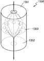
히터(130)는 원기둥과 원뿔이 조합된 형상일 수 있다. 히터(130)의 직경은 2mm 내지 3mm의 범위 중 적절한 사이즈가 채용될 수 있다. 바람직하게는, 히터(130)는 2.15mm의 직경을 갖도록 제작될 수 있으나, 이에 한정되지 않는다. 또한, 히터(130)의 길이는 20mm 내지 30mm의 범위 중 적절한 사이즈가 채용될 수 있다. 바람직하게는, 히터(130)는 19mm의 길이를 갖도록 제작될 수 있으나, 이에 한정되지 않는다. 또한, 히터(130)의 말단(131)은 예각으로 마감될 수 있으나, 이에 한정되지 않는다. 다시 말해, 히터(130)는 궐련의 내부에 삽입될 수 있는 형태라면 제한 없이 해당될 수 있다. 또한, 히터(130)는 일부 부분만 가열될 수도 있다. 예를 들어, 히터(130)의 길이가 19mm라고 가정하면, 히터(130)의 말단(131)으로부터 12mm만 가열되고, 히터(130)의 나머지 부분은 가열되지 않을 수도 있다.The
히터(130)는 전기 저항성 히터일 수 있다. 예를 들어, 히터(130)에는 전기 전도성 트랙(track)을 포함하고, 전기 전도성 트랙에 전류가 흐름에 따라 히터(130)가 가열될 수 있다.The
안정적인 사용을 위하여, 히터(130)에는 3.2 V, 2.4 A, 8 W의 규격에 따른 전력이 공급될 수 있으나, 이에 한정되지 않는다. 예를 들어, 히터(130)에 전력이 공급되는 경우, 히터(130)의 표면 온도는 400℃ 이상으로 상승할 수 있다. 히터(130)에 전력이 공급되기 시작한 때부터 15초가 초과되기 이전에 히터(130)의 표면 온도는 약 350℃까지 상승할 수 있다.For stable use, the
홀더(1)에는 별도의 온도 감지 센서가 구비될 수 있다. 또는, 홀더(1)에 온도 감지 센서가 구비되지 않고, 히터(130)가 온도 감지 센서의 역할을 수행할 수도 있다. 또는, 홀더(1)의 히터(130)가 온도 감지 센서의 역할을 수행함과 동시에 홀더(1)에는 별도의 온도 감지 센서가 더 구비될 수도 있다. 히터(130)가 온도 감지 센서의 역할을 수행하기 위하여, 히터(130)에는 발열 및 온도 감지를 위한 적어도 하나의 전기 전도성 트랙이 포함될 수 있다. 또한, 히터(130)에는 발열을 위한 제 1 전기 전도성 트랙 이외에 온도 감지를 위한 제 2 전기 전도성 트랙이 별도로 포함될 수 있다.
예를 들어, 제 2 전기 전도성 트랙에 걸리는 전압 및 제 2 전기 전도성 트랙에 흐르는 전류가 측정되면, 저항(R)이 결정될 수 있다. 이 때, 아래의 수학식 1에 의하여 제 2 전기 전도성 트랙의 온도(T)가 결정될 수 있다.For example, if the voltage across the second electrically conductive track and the current flowing through the second electrically conductive track are measured, the resistance R can be determined. At this time, the temperature T of the second electrically conductive track may be determined by

수학식 1에서, R은 제 2 전기 전도성 트랙의 현재 저항 값을 의미하고, R0는 온도 T0(예를 들어, 0℃)에서의 저항 값을 의미하고, α는 제 2 전기 전도성 트랙의 저항 온도 계수를 의미한다. 전도성 물질(예를 들어, 금속)은 고유의 저항 온도 계수를 갖고 있는바, 제 2 전기 전도성 트랙을 구성하는 전도성 물질에 따라 α는 미리 결정될 수 있다. 따라서, 제 2 전기 전도성 트랙의 저항(R)이 결정되는 경우, 상기 수학식 1에 의하여 제 2 전기 전도성 트랙의 온도(T)가 연산될 수 있다.In
히터(130)는 적어도 하나의 전기 전도성 트랙(제 1 전기 전도성 트랙 및 제 2 전기 전도성 트랙)으로 구성될 수 있다. 예를 들어, 히터(130)는 2개의 제 1 전기 전도성 트랙 및 1개 또는 2개의 제 2 전기 전도성 트랙으로 구성될 수 있으나, 이에 한정되지 않는다.
전기 전도성 트랙은 전기 저항성 물질을 포함한다. 일 예로서, 전기 전도성 트랙은 금속 물질로 제작될 수 있다. 다른 예로서, 전기 전도성 트랙은 전기 전도성 세라믹 물질, 탄소, 금속 합금 또는 세라믹 물질과 금속의 합성 물질로 제작될 수 있다.The electrically conductive track comprises an electrically resistive material. As one example, the electrically conductive track can be made of a metallic material. As another example, the electrically conductive track can be made of an electrically conductive ceramic material, carbon, a metal alloy or a composite of ceramic material and metal.
또한, 홀더(1)는 온도 감지 센서의 역할을 수행하는 전기 전도성 트랙 및 온도 감지 센서를 모두 포함할 수 있다.In addition, the
제어부(120)는 홀더(1)의 동작을 전반적으로 제어한다. 구체적으로, 제어부(120)는 배터리(110) 및 히터(130)뿐 만 아니라 홀더(1)에 포함된 다른 구성들의 동작을 제어한다. 또한, 제어부(120)는 홀더(1)의 구성들 각각의 상태를 확인하여, 홀더(1)가 동작 가능한 상태인지 여부를 판단할 수도 있다.The
제어부(120)는 적어도 하나의 프로세서를 포함한다. 프로세서는 다수의 논리 게이트들의 어레이로 구현될 수도 있고, 범용적인 마이크로 프로세서와 이 마이크로 프로세서에서 실행될 수 있는 프로그램이 저장된 메모리의 조합으로 구현될 수도 있다. 또한, 다른 형태의 하드웨어로 구현될 수도 있음을 본 실시예가 속하는 기술분야에서 통상의 지식을 가진 자라면 이해할 수 있다.The
예를 들어, 제어부(120)는 히터(130)의 동작을 제어할 수 있다. 제어부(120)는 히터(130)가 소정의 온도까지 가열되거나 적절한 온도를 유지할 수 있도록 히터(130)에 공급되는 전력의 양 및 전력이 공급되는 시간을 제어할 수 있다. 또한, 제어부(120)는 배터리(110)의 상태(예를 들어, 배터리(110)의 잔량 등)를 확인하고, 필요한 경우 알림 신호를 생성할 수 있다.For example, the
또한, 제어부(120)는 사용자의 퍼프(puff)의 유무 및 퍼프의 강도를 확인할 수 있고, 퍼프의 수를 카운팅할 수 있다. 또한, 제어부(120)는 홀더(1)가 작동하고 있는 시간을 계속하여 확인할 수 있다. 또한, 제어부(120)는 후술할 크래들(2)이 홀더(1)와 결합되었는지 여부를 확인하고, 크래들(2)과 홀더(1)의 결합 또는 분리에 따라 홀더(1)의 동작을 제어할 수 있다.In addition, the
한편, 홀더(1)는 배터리(110), 제어부(120) 및 히터(130) 외에 범용적인 구성들을 더 포함할 수 있다.Meanwhile, the
예를 들어, 홀더(1)는 시각 정보의 출력이 가능한 디스플레이 또는 촉각 정보의 출력을 위한 모터를 포함할 수 있다. 일 예로서, 홀더(1)에 디스플레이가 포함되는 경우, 제어부(120)는 디스플레이를 통하여, 사용자에게 홀더(1)의 상태에 대한 정보(예를 들어, 홀더의 사용 가능 여부 등), 히터(130)에 대한 정보(예를 들어, 예열 시작, 예열 진행, 예열 완료 등), 배터리(110)와 관련된 정보(예를 들어, 배터리(110)의 잔여 용량, 사용 가능 여부 등), 홀더(1)의 리셋과 관련된 정보(예를 들어, 리셋 시기, 리셋 진행, 리셋 완료 등), 홀더(1)의 청소와 관련된 정보(예를 들어, 청소 시기, 청소 필요, 청소 진행, 청소 완료 등), 홀더(1)의 충전과 관련된 정보(예를 들어, 충전 필요, 충전 진행, 충전 완료 등), 퍼프와 관련된 정보(예를 들어, 퍼프 횟수, 퍼프 종료 예고 등) 또는 안전과 관련된 정보(예를 들어, 사용시간 경과 등) 등을 전달 할 수 있다. 다른 예로서, 홀더(1)에 모터가 포함되는 경우, 제어부(120)는 모터를 이용하여 진동 신호를 생성함으로써, 사용자에게 상술한 정보들을 전달할 수 있다.For example, the
또한, 홀더(1)는 사용자가 홀더(1)의 기능을 제어할 수 있는 적어도 하나의 입력 장치(예를 들어, 버튼) 및/또는 크래들(2)과 결합되는 단자를 포함할 수 있다. 예를 들어, 사용자는 홀더(1)의 입력 장치를 이용하여 다양한 기능들을 실행할 수 있다. 사용자가 입력 장치를 누르는 횟수(예를 들어, 1회, 2회 등) 또는 입력 장치를 누르고 있는 시간(예를 들어, 0.1초, 0.2초 등)을 조절함으로써, 홀더(1)의 복수의 기능들 중 원하는 기능을 실행할 수 있다. 사용자가 입력 장치를 작동시킴에 따라, 홀더(1)는 히터(130)를 예열하는 기능, 히터(130)의 온도를 조절하는 기능, 궐련이 삽입되는 공간을 청소하는 기능, 홀더(1)가 작동 가능한 상태인지를 점검하는 기능, 배터리(110)의 잔량(가용 전력)을 표시하는 기능, 홀더(1)의 리셋 기능 등이 수행될 수 있다. 그러나, 홀더(1)의 기능은 상술한 예들에 한정되지 않는다.In addition, the
예를 들어, 홀더(1)는 다음과 같이 히터(130)를 제어함으로써 궐련이 삽입되는 공간을 청소할 수 있다. 예를 들어, 홀더(1)는 히터(130)를 충분히 높은 온도로 가열함으로써 궐련이 삽입되는 공간을 청소할 수 있다. 여기에서, 충분히 높은 온도는 궐련이 삽입되는 공간이 청소되기에 적절한 온도를 의미한다. 예를 들어, 홀더(1)는 삽입된 궐련에서 에어로졸이 발생될 수 있는 온도 범위 및 히터(130)를 예열하는 온도 범위 중 가장 높은 온도로 히터(130)를 가열할 수 있으나, 이에 한정되지 않는다.For example, the
또한, 홀더(1)는 소정의 시구간 동안 히터(130)의 온도를 충분히 높은 온도로 유지시킬 수 있다. 여기에서, 소정의 시구간은 궐련이 삽입되는 공간이 청소되기에 충분한 시구간을 의미한다. 예를 들어, 홀더(1)는 10초 내지 10분의 시구간 중 적절한 시간 동안 가열된 히터(130)의 온도를 유지시킬 수 있으나, 이에 한정되지 않는다. 바람직하게는, 홀더(1)는 20초 내지 1분의 범위 내에서 선택된 적절한 시구간 동안 가열된 히터(130)의 온도를 유지시킬 수 있다. 또한, 바람직하게는, 홀더(1)는 20초 내지 1분 30초의 범위 내에서 선택된 적절한 시구간동안 가열된 히터(130)의 온도를 유지시킬 수 있다.In addition, the
홀더(1)가 히터(130)를 충분히 높은 온도로 가열하고 또한 소정의 시구간 동안 가열된 히터(130)의 온도를 유지시킴에 따라, 히터(130)의 표면 및/또는 궐련이 삽입되는 공간에 증착된 물질이 휘발됨으로써 청소의 효과가 발생될 수 있다.As the
또한, 홀더(1)는 퍼프 감지 센서, 온도 감지 센서 및/또는 궐련 삽입 감지 센서를 포함할 수 있다. 예를 들어, 퍼프 감지 센서는 일반적인 압력 센서에 의하여 구현될 수 있다. 또는, 홀더(1)는, 별도의 퍼프 감지 센서가 구비됨이 없이, 히터(130)에 포함된 전기 전도성 트랙의 저항 변화에 의하여 퍼프를 감지할 수도 있다. 여기에서, 전기 전도성 트랙은 발열을 위한 전기 전도성 트랙 및/또는 온도 감지를 위한 전기 전도성 트랙을 포함한다. 또는, 홀더(1)가 히터(130)에 포함된 전기 전도성 트랙을 이용하여 퍼프를 감지하는 것과는 별개로 퍼프 감지 센서를 더 포함할 수도 있다.In addition, the
궐련 삽입 감지 센서는 일반적인 정전용량형 센서 또는 저항 센서에 의하여 구현될 수 있다. 또한, 홀더(1)는 궐련이 삽입된 상태에서도 외부 공기가 유입/유출 될 수 있는 구조로 제작될 수 있다.The cigarette insertion sensor may be implemented by a general capacitive sensor or a resistance sensor. In addition, the
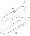
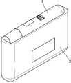
도 2a 및 도 2b는 홀더의 일 예를 여러 측면에서 도시한 도면들이다.2A and 2B are views illustrating an example of a holder in various aspects.
도 2a는 홀더(1)를 제 1 방향에서 바라본 예를 도시한 도면이다. 도 2a에 도시된 바와 같이, 홀더(1)는 원통형으로 제작될 수 있으나, 이에 한정되지 않는다. 홀더(1)의 케이스(140)는 사용자의 동작에 의하여 분리될 수 있으며, 케이스(140)의 말단(141)으로 궐련이 삽입될 수 있다. 또한, 홀더(1)에는 사용자가 홀더(1)를 제어할 수 있는 버튼(150) 및 화면(image)이 출력되는 디스플레이(160)가 포함될 수 있다.2A is a view showing an example in which the
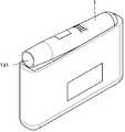
도 2b는 홀더(1)를 제 2 방향에서 바라본 예를 도시한 도면이다. 홀더(1)는 크래들(2)과 결합되는 단자(170)를 포함할 수 있다. 홀더(1)의 단자(170)가 크래들(2)의 단자(260)와 결합함으로써, 크래들(2)의 배터리(210)가 공급하는 전력에 의하여 홀더(1)의 배터리(110)가 충전될 수 있다. 또한, 단자(170)와 단자(260)를 통하여, 크래들(2)의 배터리(210)가 공급하는 전력에 의하여 홀더(1)가 동작할 수도 있고, 홀더(1)와 크래들(2)간에 통신(신호의 송수신)이 가능하다. 예를 들어, 단자(170)는 3개 또는 4개의 마이크로 핀(pin)들로 구성될 수 있으나, 이에 한정되지 않는다.2B is a view showing an example in which the
도 3은 크래들의 일 예를 도시한 구성도이다.3 is a diagram illustrating an example of a cradle.
도 3을 참조하면, 크래들(2)은 배터리(210) 및 제어부(220)를 포함한다. 또한, 크래들(2)은 홀더(1)가 삽입될 수 있는 내부 공간(230)을 포함한다. 예를 들어, 내부 공간(230)은 크래들(2)의 일 측면에 형성될 수 있다. 따라서, 크래들(2)이 별도의 뚜껑을 포함하지 않더라도 홀더(1)가 크래들(2)에 삽입되고 고정될 수 있다.Referring to FIG. 3, the
도 3에 도시된 크래들(2)에는 본 실시예와 관련된 구성요소들만이 도시되어 있다. 따라서, 도 3에 도시된 구성요소들 외에 다른 범용적인 구성요소들이 크래들(2)에 더 포함될 수 있음을 본 실시예와 관련된 기술분야에서 통상의 지식을 가진 자라면 이해할 수 있다.The
배터리(210)는 크래들(2)이 동작하는데 이용되는 전력을 공급한다. 또한, 배터리(210)는 홀더(1)의 배터리(110)를 충전하는 전력을 공급할 수 있다. 예를 들어, 홀더(1)가 크래들(2)에 삽입되어 홀더(1)의 단자(170)와 크래들(2)의 단자(260)가 결합하는 경우, 크래들(2)의 배터리(210)는 홀더(1)의 배터리(110)에 전력을 공급할 수 있다.The
또한, 홀더(1)와 크래들(2)이 결합된 경우, 배터리(210)는 홀더(1)가 동작하는데 이용되는 전력을 공급할 수 있다. 예를 들어, 홀더(1)의 단자(170)와 크래들(2)의 단자(260)가 결합되면, 홀더(1)의 배터리(110)가 방전되었는지 여부를 불문하고, 홀더(1)는 크래들(2)의 배터리(210)가 공급하는 전력을 이용하여 동작할 수 있다.In addition, when the
예를 들어, 배터리(210)는 리튬 이온 배터리일 수 있으나, 이에 한정되지 않는다. 또한, 배터리(210)의 용량은 배터리(110)의 용량보다 클 수 있고, 예를 들어 배터리(210)의 용량은 3000mAh 이상이 될 수 있다, 다만, 배터리(210)의 용량은 상술한 예에 한정되지 않는다.For example, the
제어부(220)는 크래들(2)의 동작을 전반적으로 제어한다. 제어부(220)는 크래들(2)의 모든 구성들의 동작을 제어할 수 있다. 또한, 제어부(220)는 홀더(1)와 크래들(2)이 결합되었는지를 판단하고, 크래들(2)과 홀더(1)의 결합 또는 분리에 따라 크래들(2)의 동작을 제어할 수 있다.The
예를 들어, 홀더(1)와 크래들(2)이 결합되면, 제어부(220)는 배터리(210)의 전력을 홀더(1)에 공급함으로써, 배터리(110)를 충전하거나 히터(130)를 가열시킬 수 있다. 따라서, 배터리(110)의 잔량이 적은 경우에도, 사용자는 홀더(1)와 크래들(2)을 결합하여 연속적으로 흡연할 수 있다.For example, when the
제어부(220)는 적어도 하나의 프로세서를 포함한다. 프로세서는 다수의 논리 게이트들의 어레이로 구현될 수도 있고, 범용적인 마이크로 프로세서와 이 마이크로 프로세서에서 실행될 수 있는 프로그램이 저장된 메모리의 조합으로 구현될 수도 있다. 또한, 다른 형태의 하드웨어로 구현될 수도 있음을 본 실시예가 속하는 기술분야에서 통상의 지식을 가진 자라면 이해할 수 있다.The
한편, 크래들(2)은 배터리(210) 및 제어부(220) 외에 범용적인 구성들을 더 포함할 수 있다. 예를 들어, 크래들(2)은 시각 정보의 출력이 가능한 디스플레이를 포함할 수 있다. 예를 들어, 크래들(2)에 디스플레이가 포함되는 경우, 제어부(220)는 디스플레이에 표시될 신호를 생성함으로써, 사용자에게 배터리(220)(예를 들어, 배터리(220)의 잔여 용량, 사용 가능 여부 등)와 관련된 정보, 크래들(2)의 리셋(예를 들어, 리셋 시기, 리셋 진행, 리셋 완료 등)과 관련된 정보, 홀더(1)의 청소(예를 들어, 청소 시기, 청소 필요, 청소 진행, 청소 완료 등)와 관련된 정보, 크래들(2)의 충전(예를 들어, 충전 필요, 충전 진행, 충전 완료 등)과 관련된 정보 등을 전달 할 수 있다.Meanwhile, the
또한, 크래들(2)은 사용자가 크래들(2)의 기능을 제어할 수 있는 적어도 하나의 입력 장치(예를 들어, 버튼), 홀더(1)와 결합하는 단자(260) 및/또는 배터리(210)의 충전을 위한 인터페이스(예를 들어, USB 포트 등)를 포함할 수 있다.In addition, the
예를 들어, 사용자는 크래들(2)의 입력 장치를 이용하여 다양한 기능들을 실행할 수 있다. 사용자가 입력 장치를 누르는 횟수 또는 입력 장치를 누르고 있는 시간을 조절함으로써, 크래들(2)의 복수의 기능들 중 원하는 기능을 실행할 수 있다. 사용자가 입력 장치를 작동시킴에 따라, 크래들(2)은 홀더(1)의 히터(130)를 예열하는 기능, 홀더(1)의 히터(130)의 온도를 조절하는 기능, 홀더(1) 내의 궐련이 삽입되는 공간을 청소하는 기능, 크래들(2)이 작동 가능한 상태인지를 점검하는 기능, 크래들(2)의 배터리(210)의 잔량(가용 전력)을 표시하는 기능, 크래들(2)의 리셋 기능 등이 수행될 수 있다. 그러나, 크래들(2)의 기능은 상술한 예들에 한정되지 않는다.For example, the user can execute various functions using the input device of the
도 4a 및 도 4b는 크래들의 일 예를 여러 측면에서 도시한 도면들이다.4A and 4B illustrate an example of a cradle from various aspects.
도 4a는 크래들(2)을 제 1 방향에서 바라본 예를 도시한 도면이다. 크래들(2)의 일 측면에는 홀더(1)가 삽입될 수 있는 공간(230)이 있다. 또한, 크래들(2)이 뚜껑과 같은 별도의 고정 수단을 포함하지 않더라도 홀더(1)가 크래들(2)에 삽입되고 고정될 수 있다. 또한, 크래들(2)에는 사용자가 크래들(2)를 제어할 수 있는 버튼(240) 및 화면(image)이 출력되는 디스플레이(250)가 포함될 수 있다.4A is a diagram illustrating an example of the
도 4b는 크래들(2)을 제 2 방향에서 바라본 예를 도시한 도면이다. 크래들(2)에는 삽입된 홀더(1)와 결합되는 단자(260)를 포함할 수 있다. 단자(260)가 홀더(1)의 단자(170)와 결합함으로써, 크래들(2)의 배터리(210)가 공급하는 전력에 의하여 홀더(1)의 배터리(110)가 충전될 수 있다. 또한, 단자(170)와 단자(260)을 통하여, 크래들(2)의 배터리(210)가 공급하는 전력에 의하여 홀더(1)가 동작할 수도 있고, 홀더(1)와 크래들(2)간의 신호의 송수신이 가능하다. 예를 들어, 단자(260)는 4개의 마이크로 핀(pin)들로 구성될 수 있으나, 이에 한정되지 않는다.4B is a view showing an example of the
도 1 내지 도 4b를 참조하여 상술한 바와 같이, 홀더(1)는 크래들(2)의 내부 공간(230)에 삽입될 수 있다. 또한, 홀더(1)는 크래들(2)의 내부에 완전히 삽입될 수도 있고, 크래들(2)에 삽입된 상태에서 틸트(tilt)될 수도 있다. 이하, 도 5 내지 도 7b를 참조하여, 홀더(1)가 크래들(2)에 삽입되는 예들을 설명한다.As described above with reference to FIGS. 1 to 4B, the
도 5는 홀더가 크래들에 삽입되는 일 예를 도시한 도면이다.5 is a diagram illustrating an example in which a holder is inserted into a cradle.
도 5를 참조하면, 홀더(1)가 크래들(2)에 삽입된 일 예가 도시되어 있다. 홀더(1)가 삽입될 공간(230)이 크래들(2)의 일 측면에 존재하므로, 삽입된 홀더(1)는 크래들(2)의 다른 측면들에 의하여 외부에 노출되지 않을 수 있다. 따라서, 크래들(2)은, 홀더(1)를 외부에 노출시키지 않기 위한 다른 구성(예를 들어, 뚜껑)을 포함하지 않을 수 있다.Referring to FIG. 5, an example in which the
크래들(2)에는 홀더(1)와의 결착 강도를 높이기 위하여 적어도 하나의 결착 부재(271, 272)가 포함될 수 있다. 또한, 홀더(1)에도 적어도 하나의 결착 부재(181)가 포함될 수 있다. 여기에서, 결착 부재(181, 271, 272)는 자석이 될 수 있으나, 이에 한정되지 않는다. 도 5에는, 설명의 편의를 위하여, 홀더(1)가 하나의 결착 부재(181)를 포함하고, 크래들(2)이 두 개의 결착 부재들(271, 272)을 포함하는 것으로 도시하였으나, 결착 부재(181, 271, 272)의 수는 이에 한정되지 않는다.The
홀더(1)는 제 1 위치에 결착 부재(181)를 포함할 수 있고, 크래들(2)은 제 2 위치 및 제 3 위치에 각각 결착 부재(271, 272)를 포함할 수 있다. 이때, 제 1 위치와 제 3 위치는 홀더(1)가 크래들(2)에 삽입되는 경우에 서로 마주보는 위치일 수 있다.The
홀더(1) 및 크래들(2)에 결착 부재(181, 271, 272)가 포함됨에 따라, 홀더(1)가 크래들(2)의 일 측면에 삽입되더라도, 홀더(1)와 크래들(2)이 더욱 강하게 결착될 수 있다. 다시 말해, 홀더(1) 및 크래들(2)에 단자(170, 260) 이외에 결착 부재(181, 271, 272)가 더 포함됨에 따라, 홀더(1)와 크래들(2)이 더욱 강하게 결착될 수 있다. 따라서, 크래들(2)에 별도의 구성(예를 들어, 뚜껑)이 없더라도, 삽입된 홀더(1)가 크래들(2)로부터 쉽게 분리되지 않을 수 있다.As the
또한, 단자들(170, 260) 및/또는 결착 부재들(181, 271, 272)에 의하여 홀더(1)가 크래들(2)에 완전히 삽입되었다고 판단되면, 제어부(220)은 배터리(210)의 전력을 이용하여 홀더(1)의 배터리(110)를 충전할 수 있다.In addition, when it is determined that the
도 6은 홀더가 크래들에 삽입된 상태에서 틸트되는 일 예를 도시한 도면이다.6 is a diagram illustrating an example in which the holder is tilted in a state where the holder is inserted into the cradle.
도 6을 참조하면, 홀더(1)가 크래들(2)의 내부에서 틸트되어 있다. 여기에서, 틸트는 홀더(1)가 크래들(2)에 삽입된 상태에서 일정 각도로 기울여지는 것을 의미한다.Referring to FIG. 6, the
도 5에 도시된 바와 같이, 홀더(1)가 크래들(2)에 완전히 삽입되는 경우, 사용자는 흡연을 할 수 없다. 다시 말해, 홀더(1)가 크래들(2)에 완전히 삽입되면, 홀더(1)에 궐련이 삽입될 수 없다. 따라서, 홀더(1)가 크래들(2)에 완전히 삽입된 상태에서는 사용자가 흡연을 할 수 없다.As shown in FIG. 5, when the
도 6에 도시된 바와 같이, 홀더(1)가 틸트되면, 홀더(1)의 말단(141)이 외부로 노출된다. 따라서, 사용자는 말단(141)에 궐련을 삽입하고, 생성된 에어로졸을 흡입(흡연)할 수 있다. 틸트 각(θ)은 궐련이 홀더(1)의 말단(141)에 삽입될 때, 궐련이 꺽이거나 훼손되지 않을 수 있도록 충분한 각도가 확보될 수 있다. 예를 들어, 홀더(1)는 말단(141)에 포함된 궐련 삽입 구멍 전체가 외부로 노출되는 최소 각도 또는 그 보다 큰 각도로 틸트될 수 있다. 예를 들어, 틸트 각(θ)의 범위는 0°초과 180°이하가 될 수 있고, 바람직하게는 5°이상 90°이하가 될 수 있다. 더 바람직하게는, 틸트 각(θ)의 범위는 5°이상 20°이하, 5°이상 30°이하, 5°이상 40°이하, 5°이상 50°이하, 또는 5°이상 60°이하가 될 수 있다. 더 바람직하게는, 틸트 각(θ)은 10°가 될 수 있다.As shown in FIG. 6, when the
또한, 홀더(1)가 틸트되더라도, 홀더(1)의 단자(170)와 크래들(2)의 단자(260)는 서로 결합되어 있다. 따라서, 홀더(1)의 히터(130)는 크래들(2)의 배터리(210)가 공급하는 전력에 의하여 가열될 수 있다. 따라서, 홀더(1)의 배터리(110)의 잔량이 적거나 없는 경우에도, 홀더(1)는 크래들(2)의 배터리(210)를 이용하여 에어로졸을 생성할 수 있다.In addition, even when the
도 6에는 홀더(1)가 하나의 결착 부재(182)를 포함하고, 크래들(2)이 두 개의 결착 부재들(273, 274)을 포함하는 예가 도시되어 있다. 예를 들어, 결착 부재들(182, 273, 274) 각각의 위치는 도 5를 참조하여 상술한 바와 같다. 만약, 결착 부재들(182, 273, 274)이 자석이라고 가정하면, 결착 부재(274)의 자석 강도가 결착 부재(273)의 자석 강도보다 클 수 있다. 따라서, 홀더(1)가 틸트되더라도, 결착 부재(182) 및 결착 부재(274)에 의하여, 홀더(1)는 크래들(2)과 완전히 분리되지 않을 수 있다.6 shows an example in which the
또한, 단자들(170, 260) 및/또는 결착 부재들(182, 273, 274)에 의하여 홀더(1)가 틸트되었다고 판단되면, 제어부(220)은 배터리(210)의 전력을 이용하여, 홀더(1)의 히터(130)를 가열하거나, 배터리(110)를 충전할 수 있다.In addition, when it is determined that the
도 7a 내지 도 7b는 홀더가 크래들에 삽입된 예들을 도시한 도면들이다.7A-7B illustrate examples in which a holder is inserted into a cradle.
도 7a에는 홀더(1)가 크래들(2)에 완전히 삽입된 예가 도시되어 있다. 홀더(1)가 크래들(2)에 완전히 삽입되는 경우, 사용자가 홀더(1)에 접촉하는 것을 최소화하기 위하여, 크래들(2)의 내부 공간(230)이 충분히 확보되도록 제작될 수 있다. 홀더(1)가 크래들(2)에 완전히 삽입되면, 제어부(220)는, 홀더(1)의 배터리(110)가 충전될 수 있도록, 배터리(210)의 전력을 홀더(1)에 공급한다.7A shows an example in which the
도 7b에는 홀더(1)가 크래들(2)에 삽입된 상태에서 틸트된 예가 도시되어 있다. 홀더(1)가 틸트되면, 제어부(220)는, 홀더(1)의 배터리(110)가 충전되거나, 홀더(1)의 히터(130)가 가열될 수 있도록, 배터리(210)의 전력을 홀더(1)에 공급한다.7B shows an example in which the
도 8은 홀더 및 크래들이 동작하는 일 예를 설명하기 위한 흐름도이다.8 is a flowchart illustrating an example in which the holder and the cradle operate.
도 8에 도시된 에어로졸을 생성하는 방법은 도 1에 도시된 홀더(1) 또는 도 3에 도시된 크래들(2)에서 시계열적으로 처리되는 단계들로 구성된다. 따라서, 이하에서 생략된 내용이라 하더라도 도 1에 도시된 홀더(1) 및 도 3에 도시된 크래들(2)에 관하여 이상에서 기술된 내용은 도 8의 방법에도 적용됨을 알 수 있다.The method of producing the aerosol shown in FIG. 8 consists of steps which are processed in time series in the
810 단계에서, 홀더(1)는 크래들(2)에 삽입되었는지 여부를 판단한다. 예를 들어, 제어부(120)는 홀더(1) 및 크래들(2)의 단자들(170, 260)이 서로 연결되었는지 및/또는 결착 부재들(181, 271, 272)이 동작하는지에 따라 홀더(1)가 크래들(2)에 삽입되었는지 여부를 판단할 수 있다.In
홀더(1)가 크래들(2)에 삽입된 경우에는 820 단계로 진행하고, 홀더(1)가 크래들(2)가 분리된 경우에는 830 단계로 진행한다.When the
820 단계에서, 크래들(2)은 홀더(1)가 틸트되었는지 여부를 판단한다. 예를 들어, 제어부(220)는 홀더(1) 및 크래들(2)의 단자들(170, 260)이 서로 연결되었는지 및/또는 결착 부재들(182, 273, 274)이 동작하는지에 따라 홀더(1)가 틸트되었는지 여부를 판단할 수 있다.In
820 단계에서는 크래들(2)이 홀더(1)의 틸트 여부를 판단하는 것으로 설명하였으나, 이에 한정되지 않는다. 다시 말해, 홀더(1)의 틸트 여부는 홀더(1)의 제어부(120)에 의하여 판단될 수도 있다.In
홀더(1)가 틸트된 경우에는 840 단계로 진행하고, 홀더(1)가 틸트되지 않은 경우(즉, 홀더(1)가 크래들(2)에 완전히 삽입된 경우)에는 870 단계로 진행한다.If the
830 단계에서, 홀더(1)는 홀더(1)의 사용 조건을 만족하는지 여부를 판단한다. 예를 들어, 제어부(120)는 배터리(110)의 잔량 및 홀더(1)의 다른 구성들이 정상적으로 동작할 수 있는지를 체크함으로써 사용 조건이 만족되었는지 여부를 판단할 수 있다.In
홀더(1)의 사용 조건이 만족된 경우에는 840 단계로 진행하고, 그렇지 않은 경우에는 절차를 종료한다.If the use condition of the
840 단계에서, 홀더(1)는 사용자에게 사용 가능 상태임을 알린다. 예를 들어, 제어부(120)는 홀더(1)의 디스플레이에 사용 가능함을 알리는 화면(image)을 출력할 수도 있고, 홀더(1)의 모터를 제어하여 진동 신호를 생성할 수도 있다.In
850 단계에서, 히터(130)가 가열된다. 일 예로서, 홀더(1)가 크래들(2)로부터 분리된 경우, 홀더(1)의 배터리(110)의 전력에 의하여 히터(130)가 가열될 수 있다. 다른 예로서, 홀더(1)가 틸트된 경우, 크래들(2)의 배터리(210)의 전력에 의하여 히터(130)가 가열될 수 있다.In
홀더(1)의 제어부(120) 또는 크래들(2)의 제어부(220)는 히터(130)의 온도를 실시간으로 확인하여 히터(130)에 공급되는 전력의 양 및 히터(130)에 전력이 공급되는 시간을 조절할 수 있다. 예를 들어, 제어부(120, 220)는 홀더(1)에 포함된 온도 감지 센서 또는 히터(130)의 전기 전도성 트랙을 통하여 히터(130)의 온도를 실시간으로 확인할 수 있다.The
860 단계에서, 홀더(1)는 에어로졸 생성 기작(mechanism)을 수행한다. 예를 들어, 제어부(120, 220)는 사용자가 퍼프를 수행함에 따라 변하는 히터(130)의 온도를 확인하여 히터(130)에 공급되는 전력의 양을 조절하거나 히터(130)에 전력의 공급을 중단할 수 있다. 또한, 제어부(120, 220)는 사용자의 퍼프 횟수를 카운팅할 수 있고, 일정한 퍼프 횟수(예를 들어, 1500회)에 도달하면 홀더의 청소가 필요함을 알리는 정보를 출력할 수 있다.In
870 단계에서, 크래들(2)은 홀더(1)의 충전을 수행한다. 예를 들어, 제어부(220)는 크래들(2)의 배터리(210) 전력을 홀더(1)의 배터리(110)에 공급함으로써 홀더(1)를 충전시킬 수 있다.In
한편, 제어부(120, 220)는 사용자의 퍼프 횟수 또는 홀더(1)의 동작 시간에 따라 홀더(1)의 동작을 정지시킬 수도 있다. 이하, 도 9를 참조하여, 제어부(120, 220)가 홀더(1)의 동작을 정지시키는 일 예를 설명한다.Meanwhile, the
도 9는 홀더가 동작하는 다른 예를 설명하기 위한 흐름도이다.9 is a flowchart for explaining another example in which the holder operates.
도 9에 도시된 에어로졸을 생성하는 방법은 도 1에 도시된 홀더(1) 및 도 3에서 도시된 크래들(2)에서 시계열적으로 처리되는 단계들로 구성된다. 따라서, 이하에서 생략된 내용이라 하더라도 도 1에 도시된 홀더(1) 또는 도 3에 도시된 크래들(2)에 관하여 이상에서 기술된 내용은 도 9의 방법에도 적용됨을 알 수 있다.The method of producing the aerosol shown in FIG. 9 consists of the steps processed in time series in the
910 단계에서, 제어부(120, 220)는 사용자가 퍼프하였는지 여부를 판단한다. 예를 들어, 제어부(120, 220)는 홀더(1)에 포함된 퍼프 감지 센서를 통하여 사용자가 퍼프하였는지를 판단할 수 있다. 또는, 제어부(120, 220)는 히터(130)에 포함된 전기 전도성 트랙의 저항 변화를 이용하여 사용자가 퍼프하였는지를 판단할 수도 있다. 여기에서, 전기 전도성 트랙은 발열을 위한 전기 전도성 트랙 및/또는 온도 감지를 위한 전기 전도성 트랙을 포함한다. 또는, 제어부(120, 220)는 히터(130)에 포함된 전기 전도성 트랙의 저항 변화 및 퍼프 감지 센서를 모두 이용하여 사용자가 퍼프하였는지를 판단할 수도 있다.In
920 단계에서, 사용자의 퍼프에 따라 에어로졸이 생성된다. 제어부(120, 220)가 사용자의 퍼프 및 히터(130)의 온도에 따라 히터(130)에 공급되는 전력을 조절할 수 있음은 도 8을 참조하여 상술한 바와 같다. 또한, 제어부(120, 220)는 사용자의 퍼프 횟수를 카운팅한다.In
930 단계에서, 제어부(120, 220)는 사용자의 퍼프 횟수가 퍼프 제한 횟수 이상인지 여부를 판단한다. 예를 들어, 퍼프 제한 횟수가 14회로 설정되었다고 가정하면, 제어부(120, 220)는 카운팅된 퍼프 횟수가 14회 이상인지 여부를 판단한다. 다만, 퍼프 제한 횟수는 14회로 한정되지 않는다. 예를 들어, 퍼프 제한 횟수는 10회 내지 16회 중 적절한 횟수로 설정될 수 있다.In
한편, 사용자의 퍼프 횟수가 퍼프 제한 횟수에 근접한 경우(예를 들어, 사용자의 퍼프 횟수가 12회인 경우), 제어부(120, 220)는 디스플레이 또는 진동 모터를 통하여 경고 신호를 출력할 수 있다.Meanwhile, when the number of puffs of the user is close to the number of puffs (for example, when the number of puffs of the user is 12 times), the
만약, 사용자의 퍼프 횟수가 퍼프 제한 횟수 이상인 경우에는 950 단계로 진행하고, 사용자의 퍼프 횟수가 퍼프 제한 횟수보다 적을 경우에는 940 단계로 진행한다.If the number of puffs of the user is greater than or equal to the puff limit, the process proceeds to step 950. If the number of puffs of the user is less than the puff limit, the process proceeds to step 940.
940 단계에서, 제어부(120, 220)는 홀더(1)가 동작한 시간이 동작 제한 시간 이상인지 여부를 판단한다. 여기에서, 홀더(1)가 동작한 시간은 홀더가 동작을 시작한 시점부터 현재까지 누적된 시간을 의미한다. 예를 들어, 동작 제한 시간이 10분으로 설정되었다고 가정하면, 제어부(120, 220)는 홀더(1)가 10분 이상 동작하고 있는지를 판단한다.In
한편, 홀더(1)의 동작 시간이 동작 제한 시간에 근접한 경우(예를 들어, 홀더(1)가 8분 동안 동작하고 있는 경우), 제어부(120, 220)는 디스플레이 또는 진동 모터를 통하여 경고 신호를 출력할 수 있다.On the other hand, when the operation time of the
만약, 홀더(1)가 동작 제한 시간 이상으로 동작하고 있는 경우에는 950 단계로 진행하고, 홀더(1)의 동작 시간이 동작 제한 시간보다 적은 경우에는 920 단계로 진행한다.If the
950 단계에서, 제어부(120, 220)는 홀더의 동작을 강제 종료한다. 다시 말해, 제어부(120, 220)는 홀더의 에어로졸 생성 기작을 중지시킨다. 예를 들어, 제어부(120, 220)는 히터(130)에 공급되는 전력을 차단함으로써, 홀더의 동작을 강제 종료할 수 있다.In
도 10은 크래들이 동작하는 일 예를 설명하기 위한 흐름도이다.10 is a flowchart for explaining an example in which the cradle operates.
도 10에 도시된 흐름도는 도 3에 도시된 크래들(2)에서 시계열적으로 처리되는 단계들로 구성된다. 따라서, 이하에서 생략된 내용이라 하더라도 도 3에 도시된 크래들(2)에 관하여 이상에서 기술된 내용은 도 10의 흐름도에도 적용됨을 알 수 있다.The flowchart shown in FIG. 10 consists of steps that are processed in time series in the
도 10에는 도시되지 않았으나, 이하에서 설명할 크래들(2)의 동작은, 홀더(1)가 크래들(2)에 삽입되었는지 여부를 불문하고 수행될 수 있다.Although not shown in FIG. 10, the operation of the
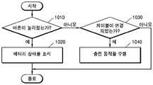
1010 단계에서, 크래들(2)의 제어부(220)는 버튼(240)이 눌려졌는지 여부를 판단한다. 만약, 버튼(240)이 눌려진 경우에는 1020 단계로 진행하고, 버튼(240)이 눌려지지 않은 경우에는 1030 단계로 진행한다.In
1020 단계에서, 크래들(2)은 배터리의 상태를 표시한다. 예를 들어, 제어부(220)는 배터리(210)의 현재 상태(예를 들어, 잔량량 등)에 대한 정보를 디스플레이(250)에 출력할 수 있다.In
1030 단계에서, 크래들(2)의 제어부(220)는 크래들(2)에 케이블이 연결되었는지 여부를 판단한다. 예를 들어, 제어부(220)는 크래들(2)에 포함된 인터페이스(예를 들어, USB 포트 등)에 케이블이 연결되었는지 여부를 판단한다. 만약, 크래들(2)에 케이블이 연결된 경우에는 1040 단계로 진행하고, 그렇지 않은 경우에는 절차를 종료한다.In
1040 단계에서, 크래들(2)은 충전 동작을 수행한다. 예를 들어, 크래들(2)은 연결된 케이블을 통하여 공급되는 전력을 이용하여 배터리(210)를 충전한다.In
도 1을 참조하여 상술한 바와 같이, 홀더(1)에는 궐련이 삽입될 수 있다. 궐련은 에어로졸 생성 물질을 포함하고, 가열된 히터(130)에 의하여 에어로졸이 생성된다.As described above with reference to FIG. 1, a cigarette may be inserted into the
이하, 도 11 내지 도 13f를 참조하여, 홀더(1)에 삽입될 수 있는 궐련의 예를 설명한다.Hereinafter, an example of a cigarette that can be inserted into the
도 11은 홀더에 궐련이 삽입된 일 예를 도시한 도면이다.11 is a diagram illustrating an example in which a cigarette is inserted into a holder.
도 11을 참조하면, 궐련(3)은 케이스(140)의 말단(141)을 통하여 홀더(1)에 삽입될 수 있다. 궐련(3)이 삽입되면, 히터(130)는 궐련(3)의 내부에 위치된다. 따라서, 가열된 히터(130)에 의하여 궐련(3)의 에어로졸 생성 물질이 가열되고, 이에 따라 에어로졸이 생성된다.Referring to FIG. 11, the
궐련(3)은 일반적인 연소형 궐련과 유사할 수 있다. 예를 들어, 궐련(3)은 에어로졸 생성 물질을 포함하는 제 1 부분(310)과 필터 등을 포함하는 제 2 부분(320)으로 구분될 수 있다. 한편, 일 실시예에 따른 궐련(3)은 제 2 부분(320)에 에어로졸 생성 물질을 포함할 수도 있다. 예를 들어, 과립 또는 캡슐의 형태로 만든 에어로졸 생성 물질이 제 2 부분(320)에 삽입될 수도 있다.The
홀더(1)의 내부에는 제 1 부분(310) 전체가 삽입되고, 제 2 부분(320)은 외부에 노출될 수 있다. 또는, 홀더(1)의 내부에 제 1 부분(310)의 일부만 삽입될 수도 있고, 제 1 부분(310) 및 제 2 부분(320)의 일부가 삽입될 수도 있다.The entirety of the
사용자는 제 2 부분(320)을 입으로 문 상태에서 에어로졸을 흡입할 수 있다. 이때, 에어로졸은 외부 공기가 제 1 부분(310)을 통과함으로써 생성되고, 생성된 에어로졸은 제 2 부분을 통과하여 사용자의 입으로 전달된다.The user may inhale the aerosol in the door state by mouth of the
외부 공기는 홀더(1)에 형성된 적어도 하나의 공기 통로를 통하여 유입(1120)될 수 있다. 예를 들어, 홀더(1)에 형성된 공기 통로의 개폐 및/또는 공기 통로의 크기는 사용자에 의하여 조절될 수 있다. 이에 따라, 무화량, 끽연감 등이 사용자에 의하여 조절될 수 있다.The outside air may be introduced 1120 through at least one air passage formed in the
또는, 외부 공기는 궐련(3)의 표면에 형성된 적어도 하나의 구멍(hole)을 통하여 유입(1110)될 수도 있다.Alternatively, the outside air may be introduced 1110 through at least one hole formed in the surface of the
도 12a 및 도 12b는 궐련의 일 예를 도시한 구성도이다.12A and 12B are diagrams illustrating an example of a cigarette.
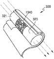
도 12a 및 도 12b를 참조하면, 궐련(3)은 담배 로드(310), 제 1 필터 세그먼트(321), 냉각 구조물(322) 및 제 2 필터 세그먼트(323)을 포함한다. 도 11을 참조하여 상술한 제 1 부분(310)은 담배 로드(310)를 포함하고, 제 2 부분(320)은 제 1 필터 세그먼트(321), 냉각 구조물(322) 및 제 2 필터 세그먼트(323)을 포함한다.12A and 12B, the
도 12a를 참조하면, 궐련(3)은 총 5 개의 래퍼들(341, 342, 343, 344, 345)에 의하여 포장될 수 있다. 한편, 도 12b를 참조하면, 궐련(3)은 총 6 개의 래퍼들(341, 342, 343, 344, 346, 347)에 의하여 포장될 수 있다. 담배 로드(310)는 제 1 래퍼(341)에 의하여 포장되고, 제 1 필터 세그먼트(321)는 제 2 래퍼(342)에 의하여 포장된다. 또한, 냉각 구조물(322)은 제 3 래퍼(343)에 의하여 포장되고, 제 2 필터 세그먼트(323)는 제 4 래퍼(344)에 의하여 포장된다.Referring to FIG. 12A, the
도 12a의 제 5 래퍼(345)는 제 1 래퍼(341), 제 2 래퍼(342), 제 3 래퍼(343) 및 제 4 래퍼(344)의 외곽에 둘러질 수 있다. 다시 말해, 궐련(3) 전체는 제 5 래퍼(345)에 의하여 이중으로 포장될 수 있다.The
한편, 도 12b의 제 6 래퍼(346)는 제 1 래퍼(341), 제 2 래퍼(342) 및 제 3 래퍼(343)의 외곽에 둘러질 수 있다. 다시 말해, 궐련(3)의 담배 로드(310), 제 1 필터 세그먼트(321) 및 냉각 구조물(322)은 제 6 래퍼에 의하여 이중으로 포장될 수 있다. 또한, 도 12b의 제 7 래퍼(347)은 제 3 래퍼(343)의 적어도 일부분 및 제 4 래퍼(344)의 외곽에 둘러질 수 있다. 다시 말해, 궐련(3)의 냉각 구조물(322)의 적어도 일부분 및 제 2 필터 세그먼트(323)은 제 7 래퍼(347)에 의하여 재포장될 수 있다.Meanwhile, the
제 1 래퍼(341) 및 제 2 래퍼(342)는 일반적인 필터 권지로 제작될 수 있다. 예를 들어, 제 1 래퍼(341) 및 제 2 래퍼(342)는 다공질 권지 또는 무다공질 권지일 수 있다. 또한, 제 1 래퍼(341) 및 제 2 래퍼(342)는 내유성을 갖는 종이류 및 알루미늄 합지 포장제로 제작될 수 있다.The
제 3 래퍼(343)는 하드 권지로 제작될 수 있다. 예를 들어, 제 3 래퍼(343)의 평량은 90g/m2일 수 있으나, 이에 제한되지 않는다.The
제 4 래퍼(344)는 내유성 하드 권지로 제작될 수 있다. 예를 들어, 제 4 래퍼(344)의 평량은 92g/m2이고, 두께는 125um일 수 있으나, 이에 제한되지 않는다.The
제 5 래퍼(345), 제 6 래퍼(346) 및 제 7 래퍼(347)는 멸균지(MFW)로 제작될 수 있다. 여기에서, 멸균지(MFW)는 인장 강도, 내수도, 평활도 등이 일반 종이보다 증진되도록 특수하게 제조된 종이를 의미한다. 예를 들어, 제 5 래퍼(345), 제 6 래퍼(346) 및 제 7 래퍼(347)의 평량은 60g/m2이고, 두께는 67um일 수 있으나, 이에 제한되지 않는다. 또한, 제 5 래퍼(345), 제 6 래퍼(346) 및 제 7 래퍼(347)의 인장 강도는 건식 기준 8kgf/15mm 내지 11kgf/15mm의 범위 이내, 습식 기준 1.0kgf/15mm일 수 있으나, 이에 제한되지 않는다.The
제 5 래퍼(345), 제 6 래퍼(346) 및 제 7 래퍼(347)는 소정의 물질이 내첨될 수 있다. 여기에서, 소정의 물질의 예로서는 실리콘이 해당될 수 있으나, 이에 한정되지 않는다. 예를 들어, 실리콘은 온도에 따른 변화가 적은 내열성, 산화되지 않는 내산화성, 각종 약품에 대한 저항성, 물에 대한 발수성, 또는 전기 절연성 등의 특성을 갖는다. 다만, 실리콘이 아니더라도, 상술한 특성들을 갖는 물질이라면 제한 없이 제 5 래퍼(345), 제 6 래퍼(346) 및 제 7 래퍼(347)에 도포(또는, 코팅)될 수 있다.The
제 5 래퍼(345), 제 6 래퍼(346) 및 제 7 래퍼(347)는 궐련(3)이 연소되는 현상을 방지할 수 있다. 예를 들어, 담배 로드(310)가 히터(130)에 의하여 가열되면, 궐련(3)이 연소될 가능성이 있다. 구체적으로, 담배 로드(310)에 포함된 물질들 중 어느 하나의 발화점 이상으로 온도가 상승될 경우, 궐련(3)이 연소될 수 있다. 이러한 경우에도, 제 5 래퍼(345), 제 6 래퍼(346) 및 제 7 래퍼(347)는 불연성 물질을 포함하므로, 궐련(3)이 연소되는 현상이 방지될 수 있다.The
또한, 제 5 래퍼(345), 제 6 래퍼(346) 및 제 7 래퍼(347)는 궐련(3)에서 생성되는 물질들에 의하여 홀더(1)가 오염되는 것을 방지할 수 있다. 사용자의 퍼프에 의하여, 궐련(3) 내에서 액체 물질들이 생성될 수 있다. 예를 들어, 궐련(3)에서 생성된 에어로졸이 외부 공기에 의하여 냉각됨으로써, 액체 물질들(예를 들어, 수분 등)이 생성될 수 있다. 제 5 래퍼(345), 제 6 래퍼(346) 및 제 7 래퍼(347)가 담배 로드(310) 및/또는 제 1 필터 세그먼트(321)를 포장함에 따라, 궐련(3) 내에서 생성된 액체 물질들이 궐련(3)의 외부로 새어 나가는 것이 방지될 수 있다. 따라서, 홀더(1)의 케이스(140) 등이 궐련(3)에서 생성된 액체 물질들에 의하여 오염되는 현상이 방지될 수 있다.In addition, the
궐련(3)의 직경은 5mm 내지 9mm의 범위 이내이고, 길이는 약 48mm일 수 있으나, 이에 한정되지 않는다. 바람직하게는, 궐련(3)의 직경은 7.2mm일 수 있으나, 이에 한정되지 않는다. 또한, 담배 로드(310)의 길이는 약 12mm, 제 1 필터 세그먼트(321)의 길이는 약 10mm, 냉각 구조물(322)의 길이는 약 14mm, 제 2 필터 세그먼트(323)의 길이는 약 12mm일 수 있으나, 이에 한정되지 않는다.The diameter of the
도 12a 및 도 12b에 도시된 궐련(3)의 구조는 일 예에 불과하며, 일부 구성이 생략될 수 있다. 예를 들어, 궐련(3)에는 제 1 필터 세그먼트(321), 냉각 구조물(322) 및 제 2 필터 세그먼트(323) 중 하나 이상이 포함되지 않을 수 있다.The structure of the
담배 로드(310)는 에어로졸 생성 물질을 포함한다. 예를 들어, 에어로졸 생성 물질은 글리세린, 프로필렌 글리콜, 에틸렌 글리콜, 디프로필렌 글리콜, 디에틸렌 글리콜, 트리에틸렌 글리콜, 테트라에틸렌 글리콜 및 올레일 알코올 중 적어도 하나를 포함할 수 있다.
또한, 담배 로드(310)는 풍미제, 습윤제 및/또는 유기산(organic acid)과 같은 다른 첨가 물질을 함유할 수 있다. 예를 들어, 풍미제는 감초, 자당, 과당 시럽, 이소감미제(isosweet), 코코아, 라벤더, 시나몬, 카르다몸, 셀러리, 호로파, 카스카릴라, 백단, 베르가못, 제라늄, 벌꿀 에센스, 장미 오일, 바닐라, 레몬 오일, 오렌지 오일, 민트 오일, 계피, 케러웨이, 코냑, 자스민, 카모마일, 멘톨, 계피, 일랑일랑, 샐비어, 스피어민트, 생강, 고수 또는 커피 등을 포함할 수 있다. 또한, 습윤제는 글리세린 또는 프로필렌 글리콜 등을 포함할 수 있다.In addition,
일 예로서, 담배 로드(310)는 담배 각초들로 충진될 수 있다. 여기에서, 담배 각초들은 담배 시트를 잘게 절단함으로써 생성될 수 있다.As an example, the
넓은 담배 시트가 좁은 공간의 담배 로드(310)에 채워지기 위해서는, 담배 시트가 용이하게 접힐 수 있도록 하는 특수한 공정이 추가적으로 요구된다. 따라서, 담배 로드(310)를 담배 시트로 충진하는 것에 비하여, 담배 로드(310)를 담배 각초들로 충진하는 것이 더 용이하며, 담배 로드(310)를 생산하는 공정의 생산성 및 효율이 더 높아질 수 있다.In order for the wide tobacco sheet to be filled in the
다른 예로서, 담배 로드(310)는 담배 시트가 세절된 복수의 담배 가닥들로 충진될 수 있다. 예를 들어, 담배 로드(310)는 복수의 담배 가닥들이 서로 같은 방향(평행)으로 또는 무작위로 합쳐져서 형성될 수 있다. 구체적으로, 담배 로드(310)는 복수의 담배 가닥들이 합쳐져서 형성되고, 히터(130)가 삽입되거나 에어로졸이 통과할 수 있는 종방향의 복수의 채널들이 형성될 수 있다. 이때, 담배 가닥들의 크기 및 배열에 의하여, 종방향의 채널들은 균일하거나 불균일할 수 있다.As another example, the
예를 들어, 담배 가닥은 아래와 같은 과정에 의하여 제조될 수 있다. 먼저, 담배 원료를 분쇄하여 에어로졸 생성 물질(예를 들어, 글리세린, 프로필렌 글리콜 등), 가향액, 바인더(예를 들어, 구아검, 잔탄검, 카르복시메틸 셀룰로오스(Carboxymethyl cellulose; CMC) 등), 물 등이 혼합된 슬러리를 만든 후, 슬러리를 이용하여 시트를 형성한다. 슬러리를 만들 때, 담배 가닥의 물성을 개질하기 위하여 천연 펄프 또는 셀룰로오스가 첨가될 수 있으며, 1개 이상의 바인더가 혼합되어 사용될 수 있다. 그리고, 시트를 건조시킨 후, 건조된 시트를 절각 또는 세절함으로써 담배 가닥이 생성될 수 있다.For example, tobacco strands can be prepared by the following procedure. First, tobacco raw materials are ground to produce aerosol generating materials (e.g., glycerin, propylene glycol, etc.), fragrance liquids, binders (e.g., guar gum, xanthan gum, Carboxymethyl cellulose (CMC), etc.), water After making the slurry mixed with the back, a sheet is formed using the slurry. When making the slurry, natural pulp or cellulose may be added to modify the physical properties of the tobacco strand, and one or more binders may be mixed and used. Then, after drying the sheet, tobacco strands may be produced by cutting or slicing the dried sheet.
담배 원료는 담배 잎 조각, 담배 줄기 및/또는 담배 처리 중 발생된 담배 미분일 수 있다. 또한, 담배 시트에는 목재 셀룰로오스 섬유와 같은 다른 첨가제가 함유될 수도 있다.The tobacco raw material may be tobacco leaf chips, tobacco stems and / or tobacco fines generated during tobacco processing. The tobacco sheet may also contain other additives such as wood cellulose fibers.
슬러리에는 에어로졸 생성 물질이 5% 내지 40%가 첨가될 수 있으며, 담배 가닥 완제품에는 에어로졸 생성 물질이 2% 내지 35%가 잔류될 수 있다. 바람직하게는, 담배 가닥 완제품에는 에어로졸 생성 물질이 10% 내지 25%가 잔류될 수 있다.5% to 40% of the aerosol generating material may be added to the slurry, and 2% to 35% of the aerosol generating material may remain in the tobacco strand finished product. Preferably, the tobacco strand finished product may have 10% to 25% residual aerosol generating material.
또한, 담배 로드(310)가 제 1 래퍼(341)에 의하여 포장되는 과정 이전에, 멘솔 또는 보습제 등의 가향액을 담배 로드(310)의 중앙에 분사하여 첨가할 수 있다.In addition, before the
담배 가닥은 가로 길이가 0.5mm 내지 2 mm, 세로 길이가 5mm 내지 50mm, 두께(높이)가 0.1 mm 내지 0.3mm인 직육면체 형상으로 제조될 수 있으나, 이에 한정되지 않는다. 바람직하게는, 담배 가닥은 가로 길이가 0.9mm, 세로 길이가 20mm, 두께(높이)가 0.2mm인 직육면체 형상으로 제조될 수 있다. 또한, 하나의 담배 가닥은 평량이 100g/m2 내지 250g/m2가 되도록 제조될 수 있으나, 이에 한정되지 않는다. 바람직하게는, 담배 가닥은 평량이 180 g/m2가 되도록 제조될 수 있다.Tobacco strands may be manufactured in a rectangular parallelepiped shape having a length of 0.5 mm to 2 mm, a length of 5 mm to 50 mm, and a thickness (height) of 0.1 mm to 0.3 mm, but are not limited thereto. Preferably, the tobacco strand may be made into a rectangular parallelepiped shape having a length of 0.9 mm, a length of 20 mm, and a thickness of 0.2 mm. In addition, one tobacco strand may be prepared so that the basis weight is 100g / m2 to 250g / m2 , but is not limited thereto. Preferably, the tobacco strand may be prepared such that the basis weight is 180 g / m2 .
담배 로드(310)가 담배 시트로 충진되는 것과 비교하여, 담배 가닥들로 충진된 담배 로드(310)는 더 많은 양의 에어로졸이 발생될 수 있다. 동일한 공간에 충진되는 것을 가정하면, 담배 시트에 비하여, 담배 가닥들이 더 넓은 표면적을 보장한다. 넓은 표면적은 에어로졸 생성 물질이 외부 공기와 접촉하는 기회가 더 많음을 의미한다. 따라서, 담배 로드(310)가 담배 가닥들로 충진될 경우, 담배 시트로 충진된 것에 비하여 더 많은 에어로졸이 생성될 수 있다.Compared to the
또한, 궐련(3)을 홀더(1)에서 분리할 때, 담배 가닥들로 충진된 담배 로드(310)가 담배 시트로 충진된 것에 비하여 보다 더 용이하게 분리될 수 있다. 다시 말해, 담배 로드(310)가 담배 가닥들로 충진될 경우, 담배 시트로 충진된 것에 비하여 홀더(1)로부터 더 용이하게 분리될 수 있다.In addition, when the
제 1 필터 세그먼트(321)은 셀룰로오스 아세테이트 필터일 수 있다. 예를 들어, 제 1 필터 세그먼트(321)는 내부에 중공을 포함하는 튜브 형태의 구조물일 수 있다. 제 1 필터 세그먼트(321)의 길이는 4mm 내지 30mm의 범위 내에서 적절한 길이가 채용될 수 있으나, 이에 한정되지 않는다. 바람직하게는, 제 1 필터 세그먼트(321)의 길이는 10 mm가 될 수 있으나, 이에 한정되지 않는다.The
제 1 필터 세그먼트(321)에 포함된 중공의 직경은 3mm 내지 4.5mm의 범위 내에서 적절한 직경이 채용될 수 있으나, 이에 한정되지 않는다.The diameter of the hollow included in the
제 1 필터 세그먼트(321)의 제조 시에 가소제의 함량을 조절함으로써 제 1 필터 세그먼트(321)의 경도가 조정될 수 있다.The hardness of the
시간이 흐름에 따라 제 1 필터 세그먼트(321)의 크기가 감소하는 것을 방지하기 위하여, 제 1 필터 세그먼트(321)의 외곽을 래퍼에 의하여 포장되도록 제조할 수 있다. 이에 따라, 제 1 필터 세그먼트(321)를 다른 구성(예를 들어, 다른 필터 세그먼트)과도 용이하게 결합할 수 있다.In order to prevent the size of the
또한, 제 1 필터 세그먼트(321)는 내부(예를 들어, 중공)에 동일 혹은 이형의 재질의 필름, 튜브 등의 구조물을 삽입하여 제조될 수 있다.In addition, the
제 1 필터 세그먼트(321)는 셀룰로오스 아세테이트를 이용하여 제조될 수 있다. 이에 따라, 히터(130)가 삽입되는 경우에 담배 로드(310)의 내부 물질이 뒤로 밀리는 현상을 방지할 수도 있고, 에어로졸의 냉각 효과가 발생될 수 있다.The
냉각 구조물(322)은 히터(130)가 담배 로드(310)을 가열함으로써 생성된 에어로졸을 냉각시킨다. 따라서, 사용자는 적당한 온도로 냉각된 에어로졸을 흡입할 수 있다.The
냉각 구조물(322)의 길이 또는 직경은 궐련(3)의 형태에 따라 다양하게 결정될 수 있다. 예를 들어, 냉각 구조물(322)의 길이는 7mm 내지 20mm의 범위 내에서 적절하게 채용될 수 있다. 바람직하게는, 냉각 구조물(322)의 길이는 약 14mm가 될 수 있으나, 이에 한정되지 않는다.The length or diameter of the
냉각 구조물(322)은 순수한 폴리락트산으로 제작되거나, 다른 분해성 폴리머와 폴리락트산을 조합하여 제작될 수 있다. 예를 들어, 냉각 구조물(322)은 압출 방식 또는 섬유의 직조 방식을 통하여 제작될 수 있다. 냉각 구조물(322)은 단위 면적 당 표면적(즉, 에어로졸과 접촉하는 표면적)을 늘리기 위하여 다양한 형태들로 제작될 수 있다.The
예를 들어, 냉각 구조물(322)은 폴리락트산으로 제조된 섬유를 직조하여 제작될 수 있다. 이 경우, 폴리락트산으로 제조된 섬유에 가향액을 도포할 수도 있다. 또는, 가향액이 도포된 별도의 섬유와 폴리락트산으로 제조된 섬유를 함께 이용하여 냉각 구조물(322)을 제작할 수도 있다. 또한, 폴리락트산 섬유를 소정의 컬러로 염색하고, 염색된 섬유를 이용하여 냉각 구조물(322)을 제작할 수도 있다.For example, the
냉각 구조물(322)의 다양한 예들은 도 13a 내지 도 13f를 참조하여 후술한다.Various examples of the
제 2 필터 세그먼트(323)도 셀룰로오스 아세테이트 필터일 수 있다. 예를 들어, 제 2 필터 세그먼트(323)는 리세스 필터로 제작될 수도 있으나, 이에 한정되지 않는다. 제 2 필터 세그먼트(323)의 길이는 4mm 내지 20mm의 범위 내에서 적절하게 채용될 수 있다. 예를 들어, 제 2 필터 세그먼트(323)의 길이는 약 12mm가 될 수 있으나, 이에 한정되지 않는다.The
제 2 필터 세그먼트(323)를 제작하는 과정에서, 제 2 필터 세그먼트(323)에 가향액을 분사함으로써 향미가 발생되도록 제작될 수도 있다. 또는, 가향액이 도포된 별도의 섬유를 제 2 필터 세그먼트(323)의 내부에 삽입할 수도 있다. 담배 로드(310)에서 생성된 에어로졸은 냉각 구조물(322)을 통과함에 따라 냉각되고, 냉각된 에어로졸이 제 2 필터 세그먼트(323)를 통하여 사용자에게 전달된다. 따라서, 제 2 필터 세그먼트(323)에 가향 요소가 첨가되는 경우, 사용자에게 전달되는 향미의 지속성이 증진되는 효과가 발생될 수 있다.In the process of manufacturing the
또한, 제 2 필터 세그먼트(323)에는 적어도 하나의 캡슐(324)이 포함될 수 있다. 여기에서, 캡슐(324)은 향료를 포함하는 내용액을 피막으로 감싼 구조일 수 있다. 예를 들어, 캡슐(324)은 구형 또는 원통형의 형상을 갖을 수 있다.In addition, the
캡슐(324)의 피막은 한천(agar), 펙틴(pectin), 알긴산 나트륨(sodium alginate), 카라기난(carrageenan), 젤라틴 또는 구아검 등의 검류 등으로 제조될 또한, 캡슐(324)의 피막을 형성하는 재료로서 경화 조제(助劑)가 더 이용될 수도 있다. 여기에서, 겔화 조제로서는, 예를 들면, 염화 칼슘군 등이 사용될 수 있다. 또한, 캡슐(324)의 피막을 형성하는 재료로서 가소제가 더 이용될 수도 있다. 여기에서, 가소제로서는 글리세린 및/또는 소르비톨이 이용될 수 있다. 또한, 캡슐(324)의 피막을 형성하는 재료로서 착색료가 더 이용될 수도 있다.The coating of the
예를 들어, 캡슐의 내용액에 포함되는 향료로서는 멘톨, 식물의 정유(精油) 등이 이용될 수 있다. 또한, 내용액에 포함되는 향료의 용매로서는, 예를 들면, 중쇄지방산 트리글리세리드(MCT)가 이용될 수 있다. 또한, 내용액은 색소, 유화제(乳化劑), 증점제(增粘劑) 등의 다른 첨가제를 함유할 수도 있다.For example, menthol, essential oil of a plant, etc. can be used as a fragrance contained in the capsule liquid. Moreover, as a solvent of the fragrance | flavor contained in a liquid content, medium chain fatty acid triglyceride (MCT) can be used, for example. In addition, the content solution may contain other additives such as a dye, an emulsifier, and a thickener.
도 13a 내지 도 13f는 궐련의 냉각 구조물의 예들을 도시한 도면들이다.13A-13F illustrate examples of a cooling structure of a cigarette.
예를 들어, 도 13a 내지 도 13f에 도시된 냉각 구조물은 순수한 폴리락트 산(PLA)으로 생산된 섬유들을 이용하여 제작될 수 있다.For example, the cooling structure shown in FIGS. 13A-13F can be fabricated using fibers produced from pure polylactic acid (PLA).
일 예로서, 필름(시트)를 충전하여 냉각 구조물을 필름(시트)을 제작하는 경우, 필름(시트)가 외부의 충격에 의하여 부스러질 수 있다. 이 경우, 냉각 구조물이 에어로졸을 냉각하는 효과가 감소된다.As an example, when the film (sheet) is filled to produce a cooling structure (film), the film (sheet) may be broken by an external impact. In this case, the effect of the cooling structure cooling the aerosol is reduced.
다른 예로서, 압출 성형 등에 의하여 냉각 구조물을 제작하는 경우, 구조물의 절단 등의 공정이 추가됨에 따라 공정의 효율이 낮아진다. 또한, 냉각 구조물을 다양한 형상들로 제작하는 것에도 한계가 있다.As another example, when manufacturing a cooling structure by extrusion molding or the like, as the process of cutting the structure is added, the efficiency of the process is lowered. There is also a limitation in manufacturing the cooling structure in various shapes.
일 실시예에 따른 냉각 구조물을 폴리락트산 섬유들을 이용하여 제작함(예를 들어, 직조)에 따라, 냉각 구조물이 외부 충격에 의하여 변형되거나 기능을 상실하게 될 위험이 낮아질 수 있다. 또한, 섬유들을 조합하는 방식을 변경함으로써, 다양한 형상을 갖는 냉각 구조물을 제작할 수 있다.By fabricating (eg, weaving) a cooling structure in accordance with one embodiment using polylactic acid fibers, the risk of the cooling structure being deformed or lost function by external impacts can be lowered. In addition, by changing the way the fibers are combined, it is possible to produce cooling structures having various shapes.
또한, 섬유들을 이용하여 냉각 구조물을 제작함으로써, 에어로졸과 접촉하는 표면적이 증대된다. 따라서, 냉각 구조물의 에어로졸 냉각 효과가 더욱 향상될 수 있다.In addition, by making the cooling structure with the fibers, the surface area in contact with the aerosol is increased. Thus, the aerosol cooling effect of the cooling structure can be further improved.
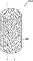
도 13a를 참조하면, 냉각 구조물(1310)은 원통형으로 제작될 수 있고, 냉각 구조물(1310)의 단면에는 적어도 하나의 공기 통로(1311)가 형성되도록 제작될 수 있다.Referring to FIG. 13A, the
도 13b를 참조하면, 냉각 구조물(1320)은 복수의 섬유들이 서로 얽힌 구조물로 제작될 수 있다. 이때, 에어로졸은 섬유들 사이로 흐를 수 있고, 냉각 구조물(1320)의 형태에 따라 와류가 형성될 수도 있다. 형성된 와류는 냉각 구조물(1320)에서 에어로졸이 접촉하는 면적을 넓혀주고, 에어로졸이 냉각 구조물(1320) 내에 머무는 시간을 증가시켜 준다. 따라서, 가열된 에어로졸이 효과적으로 냉각될 수 있다.Referring to FIG. 13B, the
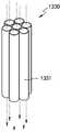
도 13c를 참조하면, 냉각 구조물(1330)은 복수 개의 다발(1331)들이 모아진 형태로 제작될 수도 있다.Referring to FIG. 13C, the
도 13d를 참조하면, 냉각 구조물(1340)은 폴리락트산, 각초 또는 숯 각각으로 제조된 과립들로 충전될 수 있다. 또한, 과립은 폴리락트산, 각초 및 참숯의 혼합물로 제조될 수도 있다. 한편, 과립은 폴리락트산, 각초 및/또는 숯 외에도 에어로졸의 냉각 효과를 증가시킬 수 있는 요소를 더 포함할 수도 있다.Referring to FIG. 13D, the
도 13e를 참조하면, 냉각 구조물(1350)은 제 1 단면(1351) 및 제 2 단면(1351)을 포함할 수 있다.Referring to FIG. 13E, the
제 1 단면(1351)은 제 1 필터 세그먼트(321)과 접경하며, 에어로졸이 유입되는 공극을 포함할 수 있다. 제 2 단면(1352)은 제 2 필터 세그먼트(323)와 접경하며, 에어로졸이 방출될 수 있는 공극을 포함할 수 있다. 예를 들어, 제 1 단면(1351)과 제 2 단면(1352)은 직경이 동일한 단일 공극을 포함할 수 있으나, 제 1 단면(1351)과 제 2 단면(1352)에 포함되는 공극의 직경 및 수는 이에 제한되지 않는다.The
더불어, 냉각 구조물(1350)은 제 1 단면(1351)과 제 2 단면(1352) 사이에, 복수의 공극들이 포함된 제 3 단면(1353)을 포함할 수 있다. 예를 들어, 제 3 단면(1353)에 포함된 복수의 공극들의 직경은 제 1 단면(1351) 및 제 2 단면(1352)에 포함된 공극의 직경보다 작을 수 있다. 또한, 제 3 단면(1353)에 포함된 공극들의 수는 제 1 단면(1351) 및 제 2 단면(1352)에 포함된 공극의 수 보다 많을 수 있다.In addition, the
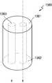
도 13f를 참조하면, 냉각 구조물(1360)은 제 1 필터 세그먼트(321)와 접경하는 제 1 단면(1361) 및 제 2 필터 세그먼트(323)와 접경하는 제 2 단면(1362)을 포함할 수 있다. 또한, 냉각 구조물(1360)은 하나 이상의 관형 요소(1363)를 포함할 수 있다. 예를 들어, 관형 요소(1363)는 제 1 단면(1361)과 제 2 단면(1362)을 관통할 수 있다. 또한, 관형 요소(1363)는 미세다공질 포장재로 포장될 수 있고, 에어로졸의 냉각 효과를 증가시킬 수 있는 충전재(예를 들어, 도 13d를 참조하여 상술한 과립)로 충전될 수 있다.Referring to FIG. 13F, the
상술한 바에 따르면, 홀더는 궐련을 가열함으로써 에어로졸을 생성시킬 수 있다. 또한, 홀더가 독립적으로 또는 홀더가 크래들에 삽입되어 틸트된 상태에서도 에어로졸을 생성시킬 수 있다. 특히, 홀더가 틸트된 경우에는 크래들의 배터리의 전력에 의하여 히터가 가열될 수 있다.According to the above, the holder can generate an aerosol by heating the cigarette. It is also possible to produce aerosols either independently of the holder or with the holder inserted into the cradle and tilted. In particular, when the holder is tilted, the heater may be heated by the power of the battery of the cradle.
도 14는 일 실시예에 따라, 크래들에서 틸트된 홀더를 이용하여 흡연을 하는 동작을 설명하기 위한 도면이다.14 is a view for explaining an operation of smoking using a holder tilted in the cradle according to an embodiment.
도 14를 참고하면, 크래들(2)은 홀더(1)를 수용하는 내부 공간이 마련되고, 홀더(1)가 내부 공간에 수용된 상태에서 홀더(1)에 궐련(3)의 삽입이 가능하도록 내부 공간과 함께 홀더(1)가 틸트(tilt)될 수 있다. 홀더(1)는 크래들(2)에 결합된 상태에서 임의의 틸트 각(θ)으로 틸트될 수 있다. 틸트 각(θ)의 범위는, 앞서 설명된 바와 같이, 0°초과 180°이하가 될 수 있고, 바람직하게는 5°이상 90°이하가 될 수 있다. 더 바람직하게는, 틸트 각(θ)의 범위는 5°이상 20°이하, 5°이상 30°이하, 5°이상 40°이하, 5°이상 50°이하, 또는 5°이상 60°이하가 될 수 있다. 더 바람직하게는, 틸트 각(θ)은 10°가 될 수 있다. 사용자는 홀더(1)의 일 말단에 궐련(3)을 삽입하고 크래들(2)을 손에 쥔 상태에서 흡연을 할 수 있다. 홀더(1), 크래들(2) 및 궐련(3) 중 적어도 하나를 포함하여 에어로졸 생성 시스템이 구축될 수 있다.Referring to FIG. 14, the
홀더(1)가 크래들(2)에서 틸트된 상태로 흡연 동작을 수행하는 경우, 홀더(1)는 크래들(2)의 배터리(210)로부터 공급된 전력을 이용하여 히터(도 1의 130)를 가열시킴으로써 궐련(3)으로부터 에어로졸을 생성할 수 있다. 한편, 홀더(1)가 틸트된 상태라 할지라도 홀더(1)는 크래들(2)에 여전히 결합된 상태이므로, 홀더(1)의 배터리(110)는 크래들(2)의 배터리(210)로부터 공급된 전력에 의하여 충전될 수 있다. 한편, 홀더(1)의 배터리(110)는 홀더(1)가 크래들(2)로부터 분리된 상태에서만 히터(도 1의 130)를 가열하기 위하여 사용될 수 있으나, 이에 제한되지 않는다.When the
크래들(2)의 제어부(220)는, 홀더(1)와 크래들(2)이 결합되었는지 여부, 홀더(1)가 틸트되었는지 여부를 판단할 수 있다. 홀더(1)와 크래들(2)이 결합된 경우, 제어부(220)는 배터리(210)에 의한 배터리(110)의 충전을 제어할 수 있다. 홀더(1)가 틸트된 경우, 제어부(220)는 배터리(210)의 전력 공급에 의한 홀더(1)의 히터(도 1의 130)의 가열, 즉 히터(도 1의 130)의 온도를 제어할 수 있다. 앞서 설명된 바와 같이, 홀더(1)가 틸트된 경우, 홀더(1)는 배터리(210)의 전력을 이용하여 연속적으로 수 회의 흡연을 할 수 있다. 이때, 예를 들어 1회의 흡연은 14회의 퍼프 단위인 것으로 설정될 수 있다.The
홀더(1)의 제어부(120)는 크래들(2)에서 틸트된 제 1 상태 및 홀더(1)가 크래들(2)로부터 분리된 제 2 상태에서의 흡연 패턴을 누적적으로 모니터링하고, 누적적으로 모니터링된 흡연 패턴이 흡연 제한 조건을 충족하는지 여부를 판단할 수 있다.The
구체적으로, 홀더(1)의 제어부(120)는 퍼프의 유무를 감지하여, 퍼프 횟수를 카운팅할 수 있다. 또한, 홀더(1)의 제어부(120)는 히터(도 1의 130)의 가열이 지속되고 있는 동작 시간을 카운팅할 수 있다. 나아가서, 제어부(120)는 홀더(1)가 크래들(2)에 결합되었는지, 틸트되었는지, 또는 분리되었는지 여부를 판단할 수 있다.Specifically, the
홀더(1)가 틸트되고 궐련(3)이 홀더(1)에 삽입된 경우, 제어부(120)는 사용자의 퍼프 횟수가 퍼프 제한 횟수에 도달하는지, 또는 홀더(1)의 동작 시간이 동작 제한 시간에 도달하는지를 판단한다. 홀더(1)가 틸트된 상태에서 퍼프 횟수 또는 동작 시간이 퍼프 제한 횟수 또는 동작 제한 시간에 도달된 경우, 제어부(120)는 히터(도 1의 130)의 가열이 중단되도록 히터(도 1의 130)를 제어할 수 있다. 이때, 홀더(1)의 제어부(120)는 크래들(2)의 제어부(220)로, 배터리(210)의 전력 공급을 중단시키도록 명령함으로써, 히터(도 1의 130)의 가열을 중단시킬 수 있다.When the
홀더(1)는 흡연 패턴과 흡연 제한 조건에 기반하여 동작될 수 있다. 흡연 패턴은 예를 들어, 삽입된 궐련(3)에 대한 퍼프 횟수를 포함할 수 있다. 흡연 제한 조건은 퍼프 제한 횟수를 포함할 수 있다. 이에 따르면, 홀더(1)는 제 1 상태 및 제 2 상태에서 누적적으로 모니터링된 퍼프 횟수가 퍼프 제한 횟수에 도달한 경우, 삽입된 궐련(3)의 가열이 중단되도록 홀더(1) 내 구비된 히터(도 1의 130)를 제어할 수 있다. 또한, 흡연 패턴은 홀더(1)의 동작 시간(예를 들어, 히터(도 1의 130)의 가열 시간)을 포함하고, 흡연 제한 조건은 동작 제한 시간을 포함할 수 있다. 이때, 홀더(1)는 제 1 상태 및 제 2 상태에서 누적적으로 모니터링된 동작 시간이 동작 제한 시간에 도달한 경우, 삽입된 궐련의 가열이 중단되도록 홀더(1) 내 구비된 히터(도 1의 130)를 제어할 수 있다.The
앞서 설명된 바와 같이, 제어부(120)는 홀더(1)가 틸트되었다가 사용자에 의해 크래들(2)에서 홀더(1)가 분리되면, 히터(도 1의 130)의 가열을 중단 시킬 수 있고, 이때 사용자는 다시 홀더(1)를 크래들(2)에 결합시킴으로써 다음 흡연을 시작할 수 있다.As described above, the
한편, 제어부(120)는 홀더(1)가 틸트되었다가 사용자에 의해 분리된 경우라 할지라도, 틸트된 상태에서 카운팅된 퍼프 횟수와 분리된 상태에서 카운팅된 퍼프 횟수를 누적하여 합산한 후 총 퍼프 횟수를 퍼프 제한 횟수와 비교하여, 히터(도 1의 130)의 가열 여부를 판단할 수 있다. 즉, 홀더(1)가 틸트되어 있거나 또는 홀더(1)가 분리되어 있다 할지라도, 홀더(1)의 제어부(120)는 퍼프 횟수를 계속적으로 모니터링한다. 퍼프 횟수와 마찬가지로, 홀더(1)의 제어부(120)는 홀더(1)가 틸트되어 있거나 또는 홀더(1)가 분리되어 있다 할지라도, 홀더(1)의 동작 시간을 계속적으로 모니터링한다. 결국, 홀더(1)의 동작의 종료, 즉 히터(도 1의 130)의 가열의 종료는, 홀더(1)의 제어부(120)의 판단에 의존할 수 있다.Meanwhile, even when the
도 15는 일 실시예에 따라 홀더가 틸트 및 분리된 경우 퍼프 횟수를 카운팅하는 방법의 흐름도이다.15 is a flow chart of a method of counting the number of puffs when the holder is tilted and detached according to one embodiment.
1501 단계에서, 홀더(1) 또는 크래들(2)은 사용자로부터 흡연 개시 요청을 수신한다. 흡연 개시 요청은, 홀더(1) 또는 크래들(2)에 구비된 입력 장치를 통하여 사용자로부터 수신될 수 있다. 홀더(1)의 제어부(120) 또는 크래들(2)의 제어부(220)는 사용자 입력이 존재하는 경우, 흡연 개시 요청이 수신되었다고 판단할 수 있다. 한편, 흡연은 홀더(1)가 틸트된 상태이거나 또는 홀더(1)가 크래들(2)로부터 분리된 상태인 경우에 가능하다. 다만, 홀더(1)가 크래들(2)로부터 분리되지 않고 홀더(1)가 틸트되지도 않은 경우, 홀더(1)는 사용자가 흡연을 하지 못하도록 동작할 수 있으며, 히터를 동작시키지 않거나 또는 사용자가 흡연을 하기에 충분하지 않은 온도 또는 시간으로만 히터를 가열시킬 수 있다. 이하, 홀더(1)가 크래들(2)에서 틸트되거나, 분리된 경우임을 가정하여 홀더(1)의 동작을 설명하도록 한다.In
1502 단계에서, 홀더(1)의 제어부(120)는 크래들(2)에 결합된 홀더(1)가 틸트되었는지 여부를 판단한다. 한편, 크래들(2)의 제어부(220)도 또한 홀더(1)가 틸트되었는지 여부를 판단할 수 있다. 홀더(1)가 틸트된 경우, 1503 단계로 진행된다. 하지만, 홀더(1)가 분리된 경우, 1507 단계로 진행된다.In
1503 단계에서, 홀더(1)의 제어부(120)는 틸트된 상태에서의 퍼프 횟수를 카운트한다.In
1504 단계에서, 홀더(1)의 제어부(120)는 틸트된 상태에서의 퍼프 횟수와 분리된 상태에서의 퍼프 횟수를 합산한다. 만약, 사용자가 틸트된 상태에서만 궐련(3)을 퍼프한 경우, 분리된 상태에서의 퍼프 횟수는 0회이다.In
1505 단계에서, 홀더(1)의 제어부(120)는 합산된 총 퍼프 횟수와 미리 설정된 퍼프 제한 횟수를 비교한다. 예를 들어, 퍼프 제한 횟수는 14회일 수 있으나, 이에 제한되지 않는다. 합산된 총 퍼프 횟수가 퍼프 제한 횟수 이하인 경우, 1502 단계로 진행된다. 하지만, 합산된 총 퍼프 횟수가 퍼프 제한 횟수에 도달한 경우, 1506 단계로 진행된다.In
1506 단계에서, 홀더(1)의 제어부(120)는 히터(도 1의 130)의 가열이 중단되도록 히터(130)를 제어한다. 한편, 홀더(1)가 여전히 틸트된 경우라면, 크래들(2)의 제어부(220)도 히터(130)의 가열이 중단되도록 히터(130)를 제어할 수 있다.In
1507 단계에서, 홀더(1)가 크래들(2)로부터 분리된 경우, 홀더(1)의 제어부(120)는 분리된 상태에서의 퍼프 횟수를 카운트한다. 이에 따라, 1504 단계에서, 홀더(1)의 제어부(120)는 분리된 상태에서 카운팅된 퍼프 횟수와 틸트된 상태에서 카운팅된 퍼프 횟수를 합산하여 총 퍼프 횟수를 카운트할 수 있다.In
도 16은 일 실시예에 따라 홀더가 틸트 및 분리된 경우 동작 시간을 카운팅하는 방법의 흐름도이다.16 is a flowchart of a method of counting operating time when a holder is tilted and detached according to one embodiment.
1601 단계에서, 홀더(1) 또는 크래들(2)은 사용자로부터 흡연 개시 요청을 수신한다.In
1602 단계에서, 홀더(1)의 제어부(120)는 크래들(2)에 결합된 홀더(1)가 틸트되었는지 여부를 판단한다. 한편, 크래들(2)의 제어부(220)도 또한 홀더(1)가 틸트되었는지 여부를 판단할 수 있다. 홀더(1)가 틸트된 경우, 1603 단계로 진행된다. 하지만, 홀더(1)가 분리된 경우, 1607 단계로 진행된다.In
1603 단계에서, 홀더(1)의 제어부(120)는 틸트된 상태에서의 동작 시간을 카운트한다.In
1604 단계에서, 홀더(1)의 제어부(120)는 틸트된 상태에서의 동작 시간과 분리된 상태에서의 동작 시간을 합산한다. 만약, 사용자가 틸트된 상태에서만 홀더(1)를 동작시킨 경우, 분리된 상태에서의 동작 시간은 0시간이다.In
1605 단계에서, 홀더(1)의 제어부(120)는 합산된 총 동작 시간과 미리 설정된 동작 제한 시간을 비교한다. 예를 들어, 동작 제한 시간은 10분일 수 있으나, 이에 제한되지 않는다. 합산된 총 동작 시간이 동작 제한 시간 이하인 경우, 1602 단계로 진행된다. 하지만, 합산된 총 동작 시간이 동작 제한 시간에 도달한 경우, 1606 단계로 진행된다.In
1606 단계에서, 홀더(1)의 제어부(120)는 히터(도 1의 130)의 가열이 중단되도록 히터(130)를 제어한다. 한편, 홀더(1)가 여전히 틸트된 경우라면, 크래들(2)의 제어부(220)도 히터(130)의 가열이 중단되도록 히터(130)를 제어할 수 있다.In
1607 단계에서, 홀더(1)가 크래들(2)로부터 분리된 경우, 홀더(1)의 제어부(120)는 분리된 상태에서의 동작 시간을 카운트한다. 이에 따라, 1604 단계에서, 홀더(1)의 제어부(120)는 분리된 상태에서 카운팅된 동작 시간과 틸트된 상태에서 카운팅된 동작 시간을 합산하여 총 동작 시간을 카운트할 수 있다.In
한편, 홀더(1)는 도 15에서 설명된 퍼프 횟수 및 도 16에서 설명된 동작 시간 중 적어도 하나가 미리 설정된 제한 조건을 만족하는 경우, 히터(도 1의 130)의 가열이 중단되도록 제어할 수 있다.Meanwhile, the
구체적으로, 홀더(1)는 제 1 상태에서 흡연이 진행되었다가 뒤이어 제 2 상태에서 흡연이 진행된 경우 제 1 상태에서 모니터링된 흡연 패턴에 제 2 상태에서 모니터링된 흡연 패턴을 누적하고, 누적된 흡연 패턴이 흡연 제한 조건을 충족한 경우 삽입된 궐련의 가열이 중단되도록 홀더(1) 내 구비된 히터(도 1의 130)를 제어한다. 또한, 홀더(1)는 제 2 상태에서 흡연이 진행되었다가 뒤이어 제 1 상태에서 흡연이 진행된 경우 제 2 상태에서 모니터링된 흡연 패턴에 제 1 상태에서 모니터링된 흡연 패턴을 누적하고, 누적된 흡연 패턴이 흡연 제한 조건을 충족한 경우 삽입된 궐련의 가열이 중단되도록 홀더(1) 내 구비된 히터(도 1의 130)를 제어한다.Specifically, the
도 17은 일 실시예에 따라 홀더에서 퍼프 횟수를 카운팅하는 방법을 설명하기 위한 도면이다.17 is a diagram for describing a method of counting the number of puffs in a holder, according to an exemplary embodiment.
도 17을 참고하면, 홀더(1)가 크래들(2)에서 틸트되고 궐련(3)이 홀더(1)에 삽입된 상태에서, 흡연이 시작될 수 있다. 사용자는 홀더(1)가 틸트된 상태에서 1번째 퍼프부터 6번째 퍼프까지 궐련(3)을 퍼프하고, 그 이후에 홀더(1)를 크래들(2)로부터 분리할 수 있다. 홀더(1)의 제어부(120)는 6회의 퍼프들이 진행되는 동안 퍼프 횟수를 누적적으로 카운팅한다.Referring to FIG. 17, smoking can be started with the
사용자는 분리된 홀더(1)를 이용하여 8회 더 퍼프할 수 있다. 이때, 홀더(1)의 제어부(120)는 분리된 홀더(1)에서 최초로 진행된 퍼프는, 틸트된 상태에서의 6번째 퍼프에 뒤이은 7번째 퍼프인 것으로 누적적으로 카운트할 수 있다. 즉, 홀더(1)의 제어부(120)는 홀더(1)가 틸트된 때부터 분리된 때까지 진행된 모든 퍼프들을 누적적으로 카운트할 수 있다. 홀더(1)의 제어부(120)는 누적된 총 퍼프 횟수가 퍼프 제한 횟수에 도달한 경우 (즉, 14번째 퍼프가 완료된 경우), 홀더(1)의 동작이 종료되도록 제어할 수 있다.The user can puff eight more times with the separated
도 18은 다른 실시예에 따라 홀더에서 퍼프 횟수를 카운팅하는 방법을 설명하기 위한 도면이다.18 is a diagram for describing a method of counting the number of puffs in a holder according to another exemplary embodiment.
도 18을 참고하면, 도 17과는 반대의 경우에 대해 설명되어 있다. 홀더(1)가 크래들(2)로부터 분리된 상태에서 궐련(3)이 홀더(1)에 삽입된 후에, 흡연이 시작될 수 있다. 사용자는 분리된 홀더(1)를 이용하여 1번째 퍼프부터 4번째 퍼프까지 궐련(3)을 퍼프하고, 그 이후에 홀더(1)를 크래들(2)에 결합하고 틸트할 수 있다. 홀더(1)의 제어부(120)는 4회의 퍼프들이 진행되는 동안 퍼프 횟수를 누적적으로 카운팅한다.Referring to FIG. 18, the case opposite to FIG. 17 is described. After the
사용자는 틸트된 홀더(1)를 이용하여 10회 더 퍼프할 수 있다. 이때, 홀더(1)의 제어부(120)는 틸트된 홀더(1)에서 최초로 진행된 퍼프는, 분리된 상태에서의 4번째 퍼프에 뒤이은 5번째 퍼프인 것으로 누적적으로 카운트할 수 있다. 즉, 홀더(1)의 제어부(120)는 홀더(1)가 분리된 때부터 틸트된 때까지 진행된 모든 퍼프들을 누적적으로 카운트할 수 있다. 홀더(1)의 제어부(120)는 누적된 총 퍼프 횟수가 퍼프 제한 횟수에 도달한 경우 (즉, 14번째 퍼프가 완료된 경우), 홀더(1)의 동작이 종료되도록 제어할 수 있다.The user can puff ten more times with the tilted
도 19는 또 다른 실시예에 따라 홀더에서 퍼프 횟수를 카운팅하는 방법을 설명하기 위한 도면이다.19 is a view for explaining a method of counting the number of puffs in a holder according to another embodiment.
도 19의 (a)를 참고하면, 사용자가 홀더(1)를 틸트된 상태로 이용하다가 홀더(1)를 크래들(2)로부터 분리하여 이용하고 뒤이어 다시 홀더(1)를 틸트하여 이용하더라도, 홀더(1)의 제어부(120)는 흡연이 개시된 이후부터(즉, 1번째 퍼프) 진행된 퍼프들을 누적적으로 카운팅할 수 있다. 유사하게, 도 19의 (b)를 참고하면, 사용자가 홀더(1)를 분리된 상태로 이용하다가 홀더(1)를 틸트하여 이용하고 뒤이어 다시 홀더(1)를 분리하여 이용하더라도, 홀더(1)의 제어부(120)는 흡연이 개시된 이후부터(즉, 1번째 퍼프) 진행된 퍼프들을 누적적으로 카운팅할 수 있다.Referring to (a) of FIG. 19, even if the user uses the
즉, 홀더(1)의 제어부(120)는 흡연이 개시된 이후에는 홀더(1)의 틸트 또는 분리와 무관하게, 진행된 퍼프 횟수를 누적적으로 카운팅하고, 누적된 총 퍼프 횟수에 기초하여 홀더(1)의 동작을 제어할 수 있다.That is, the
도 20은 일 실시예에 따라 홀더에서 동작 시간을 카운팅하는 방법을 설명하기 위한 도면이다.20 is a diagram for describing a method of counting an operation time in a holder, according to an exemplary embodiment.
도 20을 참고하면, 홀더(1)가 크래들(2)에서 틸트되고 궐련(3)이 홀더(1)에 삽입된 상태에서, 흡연이 시작될 수 있다. 사용자는 홀더(1)가 틸트된 상태에서 6분동안 궐련(3)을 퍼프하고, 그 이후에 홀더(1)를 크래들(2)로부터 분리할 수 있다. 홀더(1)의 제어부(120)는 홀더(1)가 틸트된 동안의 동작 시간을 카운팅한다.Referring to FIG. 20, with the
틸트된 상태에서의 동작 시간이 아직 동작 제한 시간에 도달하지 않은 경우, 사용자는 분리된 홀더(1)를 이용하여 더 퍼프할 수 있다. 도 20의 예에서, 사용자는 4분 동안 더 퍼프할 수 있다. 이때, 홀더(1)의 제어부(120)는 분리되기 전의 동작 시간은 이미 경과된 동작 시간인 것으로 고려할 수 있다. 즉, 홀더(1)의 제어부(120)는 홀더(1)가 틸트된 때부터 분리된 때까지 경과된 모든 동작 시간을 누적적으로 카운트할 수 있다. 홀더(1)의 제어부(120)는 누적된 총 동작 시간이 동작 제한 시간에 도달한 경우 (즉, 10분이 경과된 경우), 홀더(1)의 동작이 종료되도록 제어할 수 있다.If the operating time in the tilted state has not yet reached the operating time limit, the user can be further puffed using the separated
한편, 상술한 방법은 컴퓨터에서 실행될 수 있는 프로그램으로 작성 가능하고, 컴퓨터로 읽을 수 있는 기록매체를 이용하여 상기 프로그램을 동작시키는 범용 디지털 컴퓨터에서 구현될 수 있다. 또한, 상술한 방법에서 사용된 데이터의 구조는 컴퓨터로 읽을 수 있는 기록매체에 여러 수단을 통하여 기록될 수 있다. 상기 컴퓨터로 읽을 수 있는 기록매체는 마그네틱 저장매체(예를 들면, 롬, 램, USB, 플로피 디스크, 하드 디스크 등), 광학적 판독 매체(예를 들면, 시디롬, 디브이디 등)와 같은 저장매체를 포함한다.On the other hand, the above-described method can be written as a program that can be executed in a computer, it can be implemented in a general-purpose digital computer to operate the program using a computer-readable recording medium. In addition, the structure of the data used in the above-described method can be recorded on the computer-readable recording medium through various means. The computer-readable recording medium may include a storage medium such as a magnetic storage medium (eg, ROM, RAM, USB, floppy disk, hard disk, etc.), an optical reading medium (eg, CD-ROM, DVD, etc.). do.
본 실시예와 관련된 기술 분야에서 통상의 지식을 가진 자는 상기된 기재의 본질적인 특성에서 벗어나지 않는 범위에서 변형된 형태로 구현될 수 있음을 이해할 수 있을 것이다. 그러므로 개시된 방법들은 한정적인 관점이 아니라 설명적인 관점에서 고려되어야 한다. 본 발명의 범위는 전술한 설명이 아니라 특허청구범위에 나타나 있으며, 그와 동등한 범위 내에 있는 모든 차이점은 본 발명에 포함된 것으로 해석되어야 할 것이다.Those skilled in the art will appreciate that the present invention may be embodied in a modified form without departing from the essential characteristics of the above-described substrate. Therefore, the disclosed methods should be considered in descriptive sense only and not for purposes of limitation. The scope of the present invention is shown in the claims rather than the foregoing description, and all differences within the scope will be construed as being included in the present invention.
Claims (4)
Translated fromKorean상기 홀더 디바이스를 수용하는 내부 공간이 마련되고, 상기 홀더 디바이스가 상기 내부 공간에 수용된 상태에서 상기 수용된 홀더 디바이스와 함께 상기 내부 공간이 틸트(tilt)되는 크래들 디바이스를 포함하고,
상기 홀더 디바이스는, 상기 홀더 디바이스가 상기 크래들 디바이스에서 틸트된 제 1 상태 및 상기 홀더 디바이스가 상기 크래들 디바이스로부터 분리된 제 2 상태에서 상기 삽입된 궐련을 가열함으로써 상기 에어로졸의 생성이 가능하고,
상기 홀더 디바이스는
상기 제 1 상태에서의 흡연 패턴과 상기 제 2 상태에서의 흡연 패턴을 누적적으로 모니터링하고,
상기 제 1 상태로부터 상기 제 2 상태로 전환되거나 또는 상기 제 2 상태로부터 상기 제 1 상태로 전환되는 경우에서의 상기 누적적으로 모니터링된 흡연 패턴이 흡연 제한 조건을 충족하는지 여부를 판단하고,
상기 누적적으로 모니터링된 흡연 패턴이 상기 흡연 제한 조건을 충족하는 것으로 판단된 경우 상기 삽입된 궐련의 가열이 중단되도록 상기 홀더 디바이스 내 구비된 히터를 제어하고,
상기 흡연 패턴은 상기 삽입된 궐련에 대한 퍼프 횟수 및 상기 홀더의 동작 시간 중 적어도 하나를 포함하고,
상기 흡연 제한 조건은 퍼프 제한 횟수 및 동작 제한 시간 중 적어도 하나를 포함하는, 에어로졸 생성 시스템.A holder device for generating an aerosol by heating the inserted cigarette when a cigarette is inserted; And
An inner space for accommodating the holder device is provided, the cradle device in which the inner space is tilted together with the accommodated holder device while the holder device is accommodated in the inner space;
The holder device is capable of generating the aerosol by heating the inserted cigarette in a first state in which the holder device is tilted in the cradle device and in a second state in which the holder device is separated from the cradle device,
The holder device
Cumulatively monitoring the smoking pattern in the first state and the smoking pattern in the second state,
Determine whether the cumulatively monitored smoking pattern when transitioning from the first state to the second state or from the second state to the first state satisfies a smoking restriction condition,
Controlling a heater provided in the holder device to stop heating of the inserted cigarette when it is determined that the cumulatively monitored smoking pattern satisfies the smoking restriction condition,
The smoking pattern includes at least one of the number of puffs for the inserted cigarette and the operating time of the holder,
And the smoking limit condition comprises at least one of a puff limit number and an operation limit time.
Applications Claiming Priority (8)
| Application Number | Priority Date | Filing Date | Title |
|---|---|---|---|
| KR20160172889 | 2016-12-16 | ||
| KR1020160172889 | 2016-12-16 | ||
| KR1020170046938 | 2017-04-11 | ||
| KR20170046938 | 2017-04-11 | ||
| KR1020170077586 | 2017-06-19 | ||
| KR1020170077586AKR20180070436A (en) | 2016-12-16 | 2017-06-19 | Method and apparatus for generating generating aerosols |
| KR1020170100888 | 2017-08-09 | ||
| KR1020170100888 | 2017-08-09 |
Related Parent Applications (1)
| Application Number | Title | Priority Date | Filing Date |
|---|---|---|---|
| KR1020180010839ADivisionKR102065070B1 (en) | 2016-12-16 | 2018-01-29 | Aerosol generating system |
Related Child Applications (1)
| Application Number | Title | Priority Date | Filing Date |
|---|---|---|---|
| KR1020190033721ADivisionKR102033038B1 (en) | 2016-12-16 | 2019-03-25 | Aerosol generating system |
Publications (2)
| Publication Number | Publication Date |
|---|---|
| KR20190020305A KR20190020305A (en) | 2019-02-28 |
| KR102052714B1true KR102052714B1 (en) | 2019-12-09 |
Family
ID=62788542
Family Applications (8)
| Application Number | Title | Priority Date | Filing Date |
|---|---|---|---|
| KR1020170101348APendingKR20180070451A (en) | 2016-12-16 | 2017-08-09 | Heater and system for heating an aerosol generating substrate |
| KR1020170101350APendingKR20180070452A (en) | 2016-12-16 | 2017-08-09 | Aerosol generating system |
| KR1020170119664AActiveKR102135893B1 (en) | 2016-12-16 | 2017-09-18 | Apparatus for generating aerosols |
| KR1020180010838AActiveKR102082948B1 (en) | 2016-12-16 | 2018-01-29 | Heater and system for heating an aerosol generating substrate |
| KR1020180010839AActiveKR102065070B1 (en) | 2016-12-16 | 2018-01-29 | Aerosol generating system |
| KR1020190017391AActiveKR102052714B1 (en) | 2016-12-16 | 2019-02-14 | Aerosol generating system |
| KR1020190018812AActiveKR102033034B1 (en) | 2016-12-16 | 2019-02-18 | Heater and system for heating an aerosol generating substrate |
| KR1020190033721AActiveKR102033038B1 (en) | 2016-12-16 | 2019-03-25 | Aerosol generating system |
Family Applications Before (5)
| Application Number | Title | Priority Date | Filing Date |
|---|---|---|---|
| KR1020170101348APendingKR20180070451A (en) | 2016-12-16 | 2017-08-09 | Heater and system for heating an aerosol generating substrate |
| KR1020170101350APendingKR20180070452A (en) | 2016-12-16 | 2017-08-09 | Aerosol generating system |
| KR1020170119664AActiveKR102135893B1 (en) | 2016-12-16 | 2017-09-18 | Apparatus for generating aerosols |
| KR1020180010838AActiveKR102082948B1 (en) | 2016-12-16 | 2018-01-29 | Heater and system for heating an aerosol generating substrate |
| KR1020180010839AActiveKR102065070B1 (en) | 2016-12-16 | 2018-01-29 | Aerosol generating system |
Family Applications After (2)
| Application Number | Title | Priority Date | Filing Date |
|---|---|---|---|
| KR1020190018812AActiveKR102033034B1 (en) | 2016-12-16 | 2019-02-18 | Heater and system for heating an aerosol generating substrate |
| KR1020190033721AActiveKR102033038B1 (en) | 2016-12-16 | 2019-03-25 | Aerosol generating system |
Country Status (2)
| Country | Link |
|---|---|
| KR (8) | KR20180070451A (en) |
| CN (1) | CN208192126U (en) |
Families Citing this family (37)
| Publication number | Priority date | Publication date | Assignee | Title |
|---|---|---|---|---|
| RU2737855C1 (en) | 2017-03-30 | 2020-12-03 | Кей Ти Энд Джи Корпорейшн | Aerosol generation device and holder to accommodate device thereof |
| US12102131B2 (en) | 2017-04-11 | 2024-10-01 | Kt&G Corporation | Aerosol generating device and method for providing adaptive feedback through puff recognition |
| JP6959429B2 (en) | 2017-09-06 | 2021-11-02 | ケーティー・アンド・ジー・コーポレーション | Aerosol generator |
| KR102330296B1 (en)* | 2018-07-05 | 2021-11-24 | 주식회사 케이티앤지 | Apparatus for generating aerosols |
| WO2020019122A1 (en)* | 2018-07-23 | 2020-01-30 | 湖北中烟工业有限责任公司 | Electric heating cigarette appliance having temperature and period adjustment functions |
| JP7129485B2 (en)* | 2018-09-11 | 2022-09-01 | 京セラ株式会社 | Heater and heating tool with the same |
| EP3863446A1 (en)* | 2018-10-12 | 2021-08-18 | JT International SA | Aerosol generation device and heating chamber therefor |
| JP7267408B2 (en) | 2018-10-12 | 2023-05-01 | ジェイティー インターナショナル エス.エイ. | Aerosol generator and heating chamber therefor |
| US20220046990A1 (en)* | 2018-10-12 | 2022-02-17 | Jt International S.A. | Aerosol Generation Device And Heating Chamber Therefor |
| EP3863441B1 (en)* | 2018-10-12 | 2024-12-04 | JT International S.A. | Aerosol generation device, and heating chamber therefor |
| GB201817535D0 (en)* | 2018-10-29 | 2018-12-12 | Nerudia Ltd | Smoking substitute consumable |
| CN109288139B (en)* | 2018-11-27 | 2024-02-13 | 上海新型烟草制品研究院有限公司 | Heating component and aerosol generating device for aerosol generating device |
| KR102270185B1 (en)* | 2018-12-11 | 2021-06-28 | 주식회사 케이티앤지 | Apparatus for generating aerosol |
| KR102219853B1 (en)* | 2019-01-16 | 2021-02-24 | 주식회사 케이티앤지 | Method for controlling aerosol generating apparatus using multiple geomagnetic sensors and apparatus thereof |
| JP7153738B2 (en)* | 2019-05-21 | 2022-10-14 | 雲南中煙工業有限責任公司 | Hollow support element containing hollow temperature-reducing member, and tobacco stick containing such hollow support element |
| EP3982768A1 (en)* | 2019-06-13 | 2022-04-20 | JT International SA | An aerosol generating system, an aerosol generating device and an aerosol generating article |
| KR102269573B1 (en) | 2019-06-17 | 2021-06-24 | 주식회사 케이티앤지 | Heater assembly and aerosol generating device comprising thereof |
| KR102480482B1 (en)* | 2019-07-05 | 2022-12-23 | 주식회사 케이티앤지 | Aerosol generating device |
| KR102397449B1 (en)* | 2019-07-23 | 2022-05-12 | 주식회사 케이티앤지 | Aerosol generating device |
| US20220361574A1 (en)* | 2019-09-06 | 2022-11-17 | Jt International Sa | Aerosol Generation Device and Heating Chamber Therefor |
| KR102413551B1 (en) | 2019-10-21 | 2022-06-27 | 주식회사 케이티앤지 | Aerosol generating device including holder generating aerosol and cradle for holder, and cradle for holder generating aerosol |
| CN112369682A (en)* | 2019-11-05 | 2021-02-19 | 湖北中烟工业有限责任公司 | Smoking device |
| KR102431330B1 (en) | 2019-11-12 | 2022-08-10 | 주식회사 케이티앤지 | Aerosol generating device and operation method thereof |
| EP3987955A4 (en)* | 2019-11-29 | 2023-01-25 | Japan Tobacco Inc. | SUCTION DEVICE, TERMINAL, INFORMATION PROCESSING METHOD AND PROGRAM |
| KR20210073373A (en)* | 2019-12-10 | 2021-06-18 | 주식회사 케이티앤지 | Aerosol generating article comprising tobacco sheet and aerosol generating system using the same |
| KR102405812B1 (en)* | 2020-06-19 | 2022-06-07 | 주식회사 케이티앤지 | Heater and aerosol generating device comprising thereof |
| EP3984383B1 (en)* | 2020-10-15 | 2023-08-23 | JT International SA | A smoking article with a heated segment comprising a tobacco product |
| CN113508926B (en)* | 2021-06-24 | 2024-08-20 | 深圳麦时科技有限公司 | Aerosol generating device |
| CN113647691B (en)* | 2021-07-23 | 2024-08-02 | 深圳麦时科技有限公司 | Heating assembly and aerosol generating device |
| KR102716620B1 (en)* | 2021-10-06 | 2024-10-14 | 주식회사 케이티앤지 | Aerosol generating article and aerosol generating device used with the same |
| KR20230052172A (en) | 2021-10-12 | 2023-04-19 | 주식회사 이노아이티 | Metal fiber plane heater for aerosol generator |
| WO2023085816A1 (en)* | 2021-11-11 | 2023-05-19 | Kt&G Corporation | Aerosol generating device |
| KR102680647B1 (en)* | 2021-11-11 | 2024-07-03 | 주식회사 케이티앤지 | Aerosol generating device |
| KR102844465B1 (en)* | 2021-11-11 | 2025-08-11 | 주식회사 케이티앤지 | Aerosol generating device with surpport providing air to aerosol generating article |
| KR102713766B1 (en)* | 2022-01-19 | 2024-10-07 | 주식회사 케이티앤지 | Device for generating aerosol |
| CN120456843A (en)* | 2023-02-15 | 2025-08-08 | 韩国烟草人参公社 | Aerosol generating device and control method thereof |
| WO2024258261A1 (en)* | 2023-06-16 | 2024-12-19 | 주식회사 케이티앤지 | Heater and aerosol generation device comprising same |
Citations (1)
| Publication number | Priority date | Publication date | Assignee | Title |
|---|---|---|---|---|
| JP2016528910A (en) | 2013-08-30 | 2016-09-23 | ニコベンチャーズ ホールディングス リミテッド | Equipment with battery power adjustment function |
Family Cites Families (15)
| Publication number | Priority date | Publication date | Assignee | Title |
|---|---|---|---|---|
| KR100636287B1 (en) | 2005-07-29 | 2006-10-19 | 주식회사 케이티앤지 | Electric Cigarette Heaters |
| WO2009027959A1 (en)* | 2007-08-28 | 2009-03-05 | Oglesby & Butler Research & Development Limited | A gas powered heating unit and a heat not burn vaporising device |
| JP4739433B2 (en) | 2009-02-07 | 2011-08-03 | 和彦 清水 | Smokeless smoking jig |
| EP2253233A1 (en)* | 2009-05-21 | 2010-11-24 | Philip Morris Products S.A. | An electrically heated smoking system |
| EP2316286A1 (en)* | 2009-10-29 | 2011-05-04 | Philip Morris Products S.A. | An electrically heated smoking system with improved heater |
| GB201001944D0 (en)* | 2010-02-05 | 2010-03-24 | Kind Consumer Ltd | A simulated smoking device |
| AU2012342570B2 (en)* | 2011-11-21 | 2016-11-24 | Philip Morris Products S.A. | Ejector for an aerosol-generating device |
| EP2797445B1 (en)* | 2011-12-30 | 2016-05-04 | Philip Morris Products S.a.s. | Aerosol generating device with improved temperature distribution |
| AR091509A1 (en)* | 2012-06-21 | 2015-02-11 | Philip Morris Products Sa | ARTICLE TO SMOKE TO BE USED WITH AN INTERNAL HEATING ELEMENT |
| HUE036091T2 (en)* | 2012-12-28 | 2018-06-28 | Philip Morris Products Sa | Heating assembly for an aerosol generating system |
| GB201413027D0 (en)* | 2014-02-28 | 2014-09-03 | Beyond Twenty Ltd | Beyond 4 |
| KR101837885B1 (en)* | 2014-05-02 | 2018-03-12 | 니뽄 다바코 산교 가부시키가이샤 | Non-combustion-type flavor inhaler and computer-readable medium |
| KR20160001476U (en)* | 2014-10-28 | 2016-05-10 | 하기성 | Electronic cigarette |
| JP6637486B2 (en)* | 2015-04-02 | 2020-01-29 | 日本たばこ産業株式会社 | Flavor inhaler |
| JP3207506U (en)* | 2016-06-22 | 2016-11-17 | 佐藤 雅昭 | Portable charger case with heated cigarette storage room |
- 2017
- 2017-08-09KRKR1020170101348Apatent/KR20180070451A/enactivePending
- 2017-08-09KRKR1020170101350Apatent/KR20180070452A/enactivePending
- 2017-09-18KRKR1020170119664Apatent/KR102135893B1/enactiveActive
- 2017-12-18CNCN201721768739.2Upatent/CN208192126U/ennot_activeCeased
- 2018
- 2018-01-29KRKR1020180010838Apatent/KR102082948B1/enactiveActive
- 2018-01-29KRKR1020180010839Apatent/KR102065070B1/enactiveActive
- 2019
- 2019-02-14KRKR1020190017391Apatent/KR102052714B1/enactiveActive
- 2019-02-18KRKR1020190018812Apatent/KR102033034B1/enactiveActive
- 2019-03-25KRKR1020190033721Apatent/KR102033038B1/enactiveActive
Patent Citations (1)
| Publication number | Priority date | Publication date | Assignee | Title |
|---|---|---|---|---|
| JP2016528910A (en) | 2013-08-30 | 2016-09-23 | ニコベンチャーズ ホールディングス リミテッド | Equipment with battery power adjustment function |
Also Published As
| Publication number | Publication date |
|---|---|
| KR20180070452A (en) | 2018-06-26 |
| CN208192126U (en) | 2018-12-07 |
| KR20190019113A (en) | 2019-02-26 |
| KR102135893B1 (en) | 2020-07-21 |
| KR20180070514A (en) | 2018-06-26 |
| KR102082948B1 (en) | 2020-04-28 |
| KR20180070513A (en) | 2018-06-26 |
| KR20180070454A (en) | 2018-06-26 |
| KR20180070451A (en) | 2018-06-26 |
| KR102065070B1 (en) | 2020-01-10 |
| KR102033038B1 (en) | 2019-10-16 |
| KR102033034B1 (en) | 2019-10-16 |
| KR20190035643A (en) | 2019-04-03 |
| KR20190020305A (en) | 2019-02-28 |
Similar Documents
| Publication | Publication Date | Title |
|---|---|---|
| KR102052714B1 (en) | Aerosol generating system | |
| KR102033037B1 (en) | Method and apparatus for generating generating aerosols | |
| KR102376514B1 (en) | Method and apparatus for generating | |
| US11641879B2 (en) | Aerosol generation device and control method for aerosol generation device | |
| KR102138872B1 (en) | Aerosol generating apparatus and method for control aerosol generating apparatus | |
| KR102171333B1 (en) | Method and apparatus for generating generating aerosols | |
| US12295420B2 (en) | Aerosol generation system of preheating heater | |
| KR102065071B1 (en) | Aerosol generating apparatus | |
| KR102074931B1 (en) | Aerosol generating apparatus | |
| KR102033036B1 (en) | Aerosol generating apparatus | |
| US11432593B2 (en) | Device for cleaning smoking member, and smoking member system |
Legal Events
| Date | Code | Title | Description |
|---|---|---|---|
| A107 | Divisional application of patent | ||
| A201 | Request for examination | ||
| PA0107 | Divisional application | Comment text:Divisional Application of Patent Patent event date:20190214 Patent event code:PA01071R01D Filing date:20180129 Application number text:1020180010839 | |
| PA0201 | Request for examination | ||
| A302 | Request for accelerated examination | ||
| PA0302 | Request for accelerated examination | Patent event date:20190215 Patent event code:PA03022R01D Comment text:Request for Accelerated Examination Patent event date:20190214 Patent event code:PA03021R04I Comment text:Divisional Application of Patent | |
| PG1501 | Laying open of application | ||
| A107 | Divisional application of patent | ||
| PA0107 | Divisional application | Comment text:Divisional Application of Patent Patent event date:20190325 Patent event code:PA01071R01D Filing date:20180129 Application number text:1020180010839 | |
| E902 | Notification of reason for refusal | ||
| PE0902 | Notice of grounds for rejection | Comment text:Notification of reason for refusal Patent event date:20190703 Patent event code:PE09021S01D | |
| E701 | Decision to grant or registration of patent right | ||
| PE0701 | Decision of registration | Patent event code:PE07011S01D Comment text:Decision to Grant Registration Patent event date:20191125 | |
| PR0701 | Registration of establishment | Comment text:Registration of Establishment Patent event date:20191129 Patent event code:PR07011E01D | |
| PR1002 | Payment of registration fee | Payment date:20191202 End annual number:3 Start annual number:1 | |
| PG1601 | Publication of registration | ||
| PR1001 | Payment of annual fee | Payment date:20220921 Start annual number:4 End annual number:4 |