KR102051669B1 - Automated unlocking shackle - Google Patents
Automated unlocking shackleDownload PDFInfo
- Publication number
- KR102051669B1 KR102051669B1KR1020180074347AKR20180074347AKR102051669B1KR 102051669 B1KR102051669 B1KR 102051669B1KR 1020180074347 AKR1020180074347 AKR 1020180074347AKR 20180074347 AKR20180074347 AKR 20180074347AKR 102051669 B1KR102051669 B1KR 102051669B1
- Authority
- KR
- South Korea
- Prior art keywords
- fastening
- hole
- shackle
- unlocking means
- support member
- Prior art date
- Legal status (The legal status is an assumption and is not a legal conclusion. Google has not performed a legal analysis and makes no representation as to the accuracy of the status listed.)
- Expired - Fee Related
Links
Images


Classifications
- B—PERFORMING OPERATIONS; TRANSPORTING
- B66—HOISTING; LIFTING; HAULING
- B66C—CRANES; LOAD-ENGAGING ELEMENTS OR DEVICES FOR CRANES, CAPSTANS, WINCHES, OR TACKLES
- B66C1/00—Load-engaging elements or devices attached to lifting or lowering gear of cranes or adapted for connection therewith for transmitting lifting forces to articles or groups of articles
- B66C1/10—Load-engaging elements or devices attached to lifting or lowering gear of cranes or adapted for connection therewith for transmitting lifting forces to articles or groups of articles by mechanical means
- B66C1/22—Rigid members, e.g. L-shaped members, with parts engaging the under surface of the loads; Crane hooks
- B66C1/34—Crane hooks
- B66C1/38—Crane hooks adapted for automatic disengagement from loads on release of cable tensions
Landscapes
- Engineering & Computer Science (AREA)
- Mechanical Engineering (AREA)
- Hooks, Suction Cups, And Attachment By Adhesive Means (AREA)
- Load-Engaging Elements For Cranes (AREA)
Abstract
Translated fromKoreanDescription
Translated fromKorean본 발명은 샤클에 관한 것으로서, 보다 상세하게는 샤클과 후크를 작업자가 일일이 풀지 않아도 자동으로 잠금이 해제되는 자동 풀림 샤클에 관한 것이다.The present invention relates to a shackle, and more particularly, to an automatic release shackle that is automatically unlocked even if the operator does not loosen the shackle and the hook one by one.
일반적으로 산업현장에서 중량물은 크레인을 이용하여 운반한다.In general, heavy loads are transported by crane in industrial sites.
그런데 크레인의 로프 와이어와 중량물을 연결하는 매개체로는 샤클이 사용된다.By the way, shackle is used as a medium for connecting the rope wire of the crane and the heavy object.
샤클은 중량물에 고정된 후크에 걸 수 있는 장치로서, 대개 'U' 자형으로 이루어지는데, 작업자는 중량물에 올라가서 직접 샤클을 후크에 걸어야 한다.A shackle is a device that can be hooked to a heavy weight hook, usually of a 'U' shape. The operator must climb on the weight and hang the shackle directly on the hook.
그리고 중량물을 이동한 후 작업자는 다시 중량물의 후크에서 샤클을 제거해야 하는 작업이 반드시 수반된다.After moving the heavy object, the operator must again remove the shackle from the heavy hook.
이러한 작업은 매우 번거롭고 많은 시간이 소요된다. 특히, 중량이 매우 크거나 높은 곳에 위치하는 경우는 작업자가 일일이 이러한 작업을 하는 것이 매우 위험하다. 또 매우 터널과 같이 매우 좁은 곳에 중량물을 설치하는 경우 작업자가 진입하는 것이 어려워 더욱 문제가 된다.This is very cumbersome and time consuming. In particular, when the location is very large or high weight, it is very dangerous for the worker to do this work one by one. In addition, when the installation of a heavy object in a very narrow place, such as a tunnel, it is more difficult because the operator is difficult to enter.
이를 해결하고자 아래 선행기술과 같이 중량물의 후크로부터 샤클을 자동으로 또는 반자동으로 해제하기 위한 기술들이 공개된 바 있으나 대부분 복잡한 구조를 가지거나 작동의 정확성을 보장하기 어렵다.To solve this problem, techniques for automatically or semi-automatically releasing shackles from heavy hooks, such as the prior art, have been disclosed, but most have a complicated structure or difficult to guarantee the accuracy of operation.
뿐만 아니라 작업자가 부가적으로 조작해야 하므로 완전한 자동이라고 할 수 없었다.In addition, it was not completely automatic because the operator had to operate additionally.
이에 본 발명은 상술한 문제점을 해결하기 위한 것으로서, 본 발명의 목적은 작업자가 크레인과 중량물의 후크를 연결하는 샤클을 별도로 해제하지 않아도 크레인으로 중량물을 내려놓을 때 자동으로 체결핀이 풀려 후크가 분리될 수 있는 자동 풀림 샤클을 제공하는 것이다.Accordingly, the present invention is to solve the above-mentioned problems, the object of the present invention is to automatically release the fastening pins when the operator puts down the heavy weight to the crane even if the operator does not release the shackle connecting the hook of the crane and heavy weight, the hook is separated To provide automatic release shackles.
상기한 목적 달성을 위한 본 발명에 따른 자동 풀림 샤클은, 중량물의 후크와 크레인을 연결하는 샤클에 있어서, 평판 형상이고 상호 마주보는 한 쌍의 지지부재와 상기 지지부재를 서로 이격되게 연결하는 이음부재로 이루어져 단면이 'H' 형상으로 이루어지는 샤클몸체; 상기 후크가 걸리도록 상기 양 지지부재의 하부를 관통하되, 탄성 압축된 상태로 고정되는 체결수단; 상기 지지부재의 측면에 밀착되어 상하 슬라이딩 가능하게 움직이고, 상기 체결수단의 단부가 걸리며, 중앙에 장공이 형성된 잠금해제수단; 상기 잠금해제수단의 양측으로 구비되어 상기 잠금해제수단의 상하 슬라이딩을 안내하는 가이드부재; 및 상기 장공을 통해 상기 지지부재와 상기 잠금해제수단의 상단을 연결하는 인장스프링;을 포함하여 이루어져, 상기 샤클몸체가 중량물 상부면과 접촉하면 상기 잠금해제수단이 밀려 상승하여 상기 체결수단의 단부가 이탈하면서 잠금상태가 해제될 수 있다.Automatic release shackle according to the present invention for achieving the above object, in the shackle connecting the heavy hook and the crane, a pair of flat plate-shaped and mutually opposite support member and the joint member for connecting the support member spaced apart from each other Shackle body consisting of a cross-section 'H' shape; Fastening means penetrating the lower portions of the support members so that the hooks are caught and fixed in an elastically compressed state; An unlocking means in close contact with a side surface of the support member and slidably movable, having an end of the fastening means and having a long hole in a center thereof; Guide members provided on both sides of the unlocking means to guide the vertical sliding of the unlocking means; And a tension spring connecting the upper end of the support member and the unlocking means through the long hole. When the shackle body is in contact with the upper surface of the heavy object, the unlocking means is pushed up to raise the end of the fastening means. The lock may be released while leaving.
여기서, 상기 체결수단은, 상기 지지부재 중 어느 하나의 하부 측면에 수직으로 결합되는 중공 형상의 하우징; 봉 형상으로 이루어져 일측은 상기 하우징 내에 수용되고 타측은 상기 각 지지부재의 하부를 관통하여 돌출되며, 일단은 상기 하우징의 단부에 걸리고 타단은 상기 잠금해제수단에 걸리며, 중간에 돌출된 리브가 형성되는 체결핀; 및 상기 하우징 내에서 상기 리브와 지지부재의 사이에 탄성적으로 수용되는 압축스프링;을 포함하여 이루어질 수 있다.Here, the fastening means, the housing of the hollow shape vertically coupled to any one of the lower side of the support member; Consists of a rod shape, one side is received in the housing and the other side is protruded through the lower portion of each support member, one end is caught by the end of the housing and the other end is caught by the unlocking means, the fastening rib is formed in the middle pin; And a compression spring elastically received between the rib and the support member in the housing.
이때, 상기 체결핀의 타단에는 상기 체결핀의 외경보다 짧은 외경을 가지는 걸림홈이 형성될 수 있다.At this time, the other end of the fastening pin may be formed with a locking groove having an outer diameter shorter than the outer diameter of the fastening pin.
또 다르게 상기 체결수단은, 봉 형상으로 이루어져 상기 각 지지부재의 하부를 관통하되, 일단에는 스토퍼가 형성되고 타단에는 상기 잠금해제수단에 걸리도록 걸림홈이 형성되는 체결핀; 상기 스토퍼와 일측 지지부재 사이에 탄성적으로 게재되는 압축스프링; 상기 일측 지지부재에 형성되어 상기 압축스프링에 의해 후진하는 상기 체결핀의 걸림홈에 걸리게 함으로써 상기 체결핀을 잡아주는 홀딩체;를 포함하여 이루어질 수 있다.In another embodiment, the fastening means may include a fastening pin formed in a rod shape and having a stopper formed at one end thereof and having a stopper formed at one end thereof and engaging the unlocking means at the other end thereof; A compression spring elastically placed between the stopper and one side support member; And a holding body formed on the one side support member to hold the fastening pin by engaging the locking groove of the fastening pin retracted by the compression spring.
이때, 상기 홀딩체는, 상기 지지부재의 측면에 관통, 형성되는 가이드 홀에 삽입되고 단부에 경사면이 형성된 슬라이더와, 상기 가이드 홀에 삽입되어 상기 슬라이더를 탄성 지지하는 홀딩스프링으로 구성될 수 있다.In this case, the holding body may include a slider which is inserted into a guide hole penetrating and formed on a side surface of the support member and has an inclined surface at an end thereof, and a holding spring inserted into the guide hole to elastically support the slider.
그리고 상기 잠금해제수단은, 평판 형상으로 이루어지고, 양측에 상기 가이드 부재에 걸릴 수 있는 단턱이 형성되며, 중앙에 상하로 긴 장공이 형성되고, 상기 장공의 하측에 상기 체결핀의 단부가 통과하여 걸릴 수 있는 체결공이 형성될 수 있다.And the unlocking means is formed in a flat plate shape, the stepped to be caught by the guide member on both sides is formed, the long hole is formed in the center up and down, the end of the fastening pin is passed through the lower side of the hole Fastening holes that can be caught may be formed.
여기서, 상기 체결공은, 상기 체결핀 단부의 외경보다 더 긴 내경을 가지는 이탈홀과, 상기 체결핀의 단부가 걸리도록 상기 체결핀 단부의 외경보다 짧은 내경을 가지는 걸림홀이 서로 중첩되되, 상기 걸림홀이 상기 이탈홀의 상측에 형성되도록 중첩될 수 있다.Here, the fastening hole, the separation hole having an inner diameter longer than the outer diameter of the end of the fastening pin and the engaging hole having an inner diameter shorter than the outer diameter of the end of the fastening pin so that the end of the fastening pin is overlapped with each other, The locking hole may overlap to be formed above the separation hole.
본 발명의 다른 실시 예로서, 중량물의 후크와 크레인을 연결하는 샤클에 있어서, 평판 형상이고 상부에 연결핀이 관통하도록 상하로 긴 유격홀이 형성되며 상호 마주보는 한 쌍의 지지부재와, 상기 지지부재를 서로 이격되게 연결하는 이음부재로 이루어져 단면이 'H' 형상으로 이루어지는 샤클몸체; 상기 후크가 걸리도록 상기 양 지지부재의 하부를 관통하되, 탄성 압축된 상태로 고정되는 체결수단; 상부가 상기 연결핀 일단에 결합되고, 상기 지지부재의 측면에 밀착되어 상하 슬라이딩 가능하게 움직이며, 하부에 상기 체결수단의 단부가 걸리고, 중앙에 장공이 형성된 잠금해제수단; 상기 잠금해제수단의 양측으로 구비되어 상기 잠금해제수단의 상하 슬라이딩을 안내하는 가이드부재; 및 상기 장공을 통해 상기 지지부재와 상기 잠금해제수단의 상단을 연결하는 인장스프링;을 포함하여 이루어져, 상기 샤클몸체가 중량물 상부면과 접촉하면 상기 연결핀의 하강과 함께 상기 잠금해제수단이 하강하여 상기 체결수단의 단부가 이탈하면서 잠금상태가 해제될 수 있다.In another embodiment of the present invention, in a shackle connecting a heavy hook and a crane, a pair of support members having a flat plate shape and a long clearance hole formed vertically long so that the connecting pin penetrates therebetween and face each other, and the support Shackle body consisting of a joint member for connecting the members to be spaced apart from each other in the 'H' shape; Fastening means penetrating the lower portions of the support members so that the hooks are caught and fixed in an elastically compressed state; An upper end coupled to one end of the connecting pin, the upper end sliding in close contact with the side of the support member, the lower end of the fastening means being caught, and an unlocking means having a long hole in the center; Guide members provided on both sides of the unlocking means to guide the vertical sliding of the unlocking means; And a tension spring connecting the upper end of the support member and the unlocking means through the long hole. When the shackle body is in contact with the upper surface of the heavy material, the unlocking means descends together with the lowering of the connecting pin. The locking state may be released while the end of the fastening means is separated.
여기서, 상기 체결수단은, 상기 지지부재 중 어느 하나의 하부 측면에 수직으로 결합되는 중공 형상의 하우징; 봉 형상으로 이루어져 일측은 상기 하우징 내에 수용되고 타측은 상기 각 지지부재의 하부를 관통하여 돌출되며, 일단은 상기 하우징의 단부에 걸리고 타단은 상기 잠금해제수단에 걸리며, 중간에 돌출된 리브가 형성되는 체결핀; 및 상기 하우징 내에서 상기 리브와 지지부재의 사이에 탄성적으로 수용되는 압축스프링;을 포함하여 이루어질 수 있다.Here, the fastening means, the housing of the hollow shape vertically coupled to any one of the lower side of the support member; Consists of a rod shape, one side is received in the housing and the other side is protruded through the lower portion of each support member, one end is caught by the end of the housing and the other end is caught by the unlocking means, the fastening rib is formed in the middle pin; And a compression spring elastically received between the rib and the support member in the housing.
또 다르게 상기 체결수단은, 봉 형상으로 이루어져 상기 각 지지부재의 하부를 관통하되, 일단에는 스토퍼가 형성되고 타단에는 상기 잠금해제수단에 걸리도록 걸림홈이 형성되는 체결핀; 상기 스토퍼와 일측 지지부재 사이에 탄성적으로 게재되는 압축스프링; 및 상기 일측 지지부재에 형성되어 상기 압축스프링에 의해 후진하는 상기 체결핀의 걸림홈에 걸리게 함으로써 상기 체결핀을 잡아주는 홀딩체;를 포함하여 이루어질 수 있다.In another embodiment, the fastening means may include a fastening pin formed in a rod shape and having a stopper formed at one end thereof and having a stopper formed at one end thereof and engaging the unlocking means at the other end thereof; A compression spring elastically placed between the stopper and one side support member; And a holding body formed on the one side support member to hold the locking pin by catching the locking groove of the locking pin retracted by the compression spring.
그리고 상기 잠금해제수단은, 평판 형상으로 이루어지고, 양측에 상기 가이드 부재에 걸릴 수 있는 단턱이 형성되며, 상부에 상기 연결핀이 관통하는 핀홀이 형성되고, 중앙에 상하로 긴 장공이 형성되며, 상기 장공의 하측에 상기 체결핀의 단부가 통과하여 걸릴 수 있는 체결공이 형성될 수 있다.And the unlocking means is made of a flat plate shape, the stepped to be caught by the guide member is formed on both sides, a pinhole through which the connecting pin penetrates is formed in the upper, the long and vertical holes are formed in the center, A fastening hole that can be caught by passing through the end of the fastening pin may be formed on the lower side of the long hole.
이때, 상기 체결공은, 상기 체결핀 단부의 외경보다 더 긴 내경을 가지는 이탈홀과, 상기 체결핀의 단부가 걸리도록 상기 체결핀 단부의 외경보다 짧은 내경을 가지는 걸림홀이 서로 중첩되되, 상기 이탈홀이 상기 걸림홀의 상측에 형성되도록 중첩될 수 있다.In this case, the fastening hole, the separation hole having an inner diameter longer than the outer diameter of the end of the fastening pin and the engaging hole having an inner diameter shorter than the outer diameter of the end of the fastening pin so that the end of the fastening pin is overlapped with each other, The separation hole may be overlapped to be formed above the locking hole.
상기와 같은 구성으로 이루어진 본 발명에 따르면, 크레인으로 중량물을 내려 놓음과 동시에 잠금해제수단이 상승하고 체결핀이 자동으로 후진하면서 후크가 분리되기 때문에 작업자가 일일이 샤클을 해제하는 작업을 할 필요가 없다.According to the present invention having the configuration described above, the operator does not need to release the shackles because the hook is separated while the locking means is raised and the fastening pin is automatically retracted at the same time the weight is put down by the crane. .
그리고 후크에 체결할 때도 체결핀을 밀어 체결핀의 단부가 체결공을 통과하면서 걸림홀에 걸리므로 아주 쉽게 샤클을 체결할 수 있다.Also, when fastening to the hook, the end of the fastening pin is pushed through the fastening hole while the fastening hole is caught in the locking hole, so that the shackle can be fastened very easily.
도 1은 본 발명의 제1 실시 예를 따른 자동 풀림 샤클을 나타내는 사시도
도 2은 도 1에 도시된 본 발명의 측면도
도 3은 도 1에 도시된 본 발명의 정면도
도 4는 본 발명의 작동상태도
도 5는 본 발명의 제2 실시 예를 따른 자동 풀림 샤클을 나타내는 측면도
도 6은 도 5에 도시된 본 발명의 저면도
도 7은 도 5에 도시된 본 발명의 작동상태도
도 8은 본 발명의 제3 실시 예를 따른 자동 풀림 샤클을 나타내는 측면도
도 9는 도 8에 도시된 본 발명의 정면도
도 10은 도 8에 도시된 본 발명의 작동상태도
도 11은 본 발명의 제4 실시 예를 따른 자동 풀림 샤클을 나타내는 측면도
도 12는 도 11에 도시된 본 발명의 작동상태도1 is a perspective view showing an automatic release shackle according to a first embodiment of the present invention
Figure 2 is a side view of the present invention shown in Figure 1
3 is a front view of the present invention shown in FIG.
4 is an operating state diagram of the present invention
Figure 5 is a side view showing an automatic release shackle according to a second embodiment of the present invention
6 is a bottom view of the present invention shown in FIG.
7 is an operating state diagram of the present invention shown in FIG.
Figure 8 is a side view showing an automatic release shackle according to a third embodiment of the present invention
9 is a front view of the present invention shown in FIG.
10 is an operating state diagram of the present invention shown in FIG.
11 is a side view showing an automatic release shackle according to a fourth embodiment of the present invention.
12 is an operating state diagram of the present invention shown in FIG.
이하, 본 발명에 따른 일 실시 예를 첨부한 도면을 참조하여 보다 상세하게 설명하기로 한다.Hereinafter, an embodiment according to the present invention will be described in detail with reference to the accompanying drawings.
참고로, 도면을 참조한 설명은 본 발명을 더 쉽게 이해하기 위한 것으로, 본 발명의 범주가 그것에 의해 한정되는 것은 아니다. 그리고 본 발명을 설명함에 있어, 관련된 공지기술에 대한 구체적인 설명이 본 발명의 요지를 불필요하게 흐릴 수 있다고 판단될 경우, 상세한 설명은 생략하기로 한다.For reference, the description with reference to the drawings is for easier understanding of the present invention, and the scope of the present invention is not limited thereto. In the following description of the present invention, when it is determined that the detailed description of the related known technology may unnecessarily obscure the subject matter of the present invention, the detailed description will be omitted.
본 발명은 크레인과 같은 중장비로 매우 무거운 중량물을 걸이 이송할 때 중량물에 구비된 후크에 걸어 크레인으로 이송할 수 있는 샤클에 관한 것으로서, 후크에 걸린 샤클을 작업자가 해제할 필요가 없이 자동으로 해제될 수 있는 자동 풀림 샤클의 구조에 관한 것이다.The present invention relates to a shackle which can be transported to a crane by hooking a hook provided on a heavy material when a heavy load such as a crane is transported by a heavy equipment, and is automatically released without a worker having to release the shackle caught on the hook. The structure of the automatic release shackle can be.
< 제1 실시 예><First embodiment>
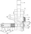
도 1은 본 발명의 제1 실시 예를 따른 자동 풀림 샤클을 나타내는 사시도이고, 도 2은 도 1에 도시된 본 발명의 측면도, 그리고 도 3은 도 1에 도시된 본 발명의 정면도를 나타낸다.1 is a perspective view illustrating an automatic release shackle according to a first embodiment of the present invention, FIG. 2 is a side view of the present invention shown in FIG. 1, and FIG. 3 is a front view of the present invention shown in FIG. 1.
본 발명은 크게 샤클몸체(100), 체결수단(200), 잠금해제수단(300), 가이드부재(400), 인장스프링(500)을 포함하여 구성될 수 있다.The present invention can be largely configured to include a
먼저, 샤클몸체(100)에 대해 설명한다.First, the
상기 샤클몸체(100)는 도시된 바와 같이, 대략 단면이 'H' 형상을 가진다.The
상기 샤클몸체(100)는 평판 형상의 동일한 두 지지부재(110)가 마주보도록 수직으로 배치되고 두 지지부재(110) 사이에 수평으로 이음부재(120)가 구비되어 두 지지부재(110)를 이격되게 연결한다.The
그리고 상기 샤클몸체(100)는 큰 중량, 특히 인장력을 견디도록 충분한 강도를 가진 재질로 이루어질 수 있다.And the
상기 샤클몸체(100)의 상부에는 크레인(미도시)과 연결되는 연결부재(20)가 연결핀(30)에 의해 핀결합될 수 있다.A
또 상기 샤클몸체(100)의 하부에는 후술하는 체결수단(200)의 체결핀(220)이 관통할 수 있도록 관통공(110a)이 형성된다. 즉 상기 각 지지부재(110)의 하부에 관통공(110a)이 형성된다.In addition, a
다음으로 체결수단에 대해 설명하기로 한다.Next, the fastening means will be described.
상기 체결수단(200)은 상기 샤클몸체(100)의 하부에 결합되는 것으로서, 후크(10)를 걸어 체결하기 위한 구성이다.The fastening means 200 is to be coupled to the lower portion of the
상기 체결수단(200)은 하우징(210), 체결핀(220), 압축스프링(230)을 포함하여 구성될 수 있다.The fastening means 200 may include a
상기 하우징(210)은 중공의 원통 형상으로 이루어질 수 있고, 상기 지지부재(110)의 하부 측면에 수직으로 결합된다.The
그리고 상기 하우징(210)의 단부는 개방되지 않고 막힌 상태일 수 있으며 분해를 위해 캡(211)으로 결합할 수 있다.And the end of the
상기 하우징(210) 내에는 체결핀(220)이 수용된다.The
구체적으로 상기 체결핀(220)은 환봉 형상으로 이루어지고 일측은 상기 하우징(210) 내에 길이방향을 따라 수용되고 타측은 상기 지지부재(110)의 하부를 관통한다. 즉, 상기 지지부재(110)에 형성된 관통공(110a)들을 관통하여 단부가 외부로 돌출될 수 있다.Specifically, the
이때, 상기 체결핀(220)은 상기 관통공(110a)을 통해 출입 가능하도록 상기 체결핀(220)의 외경보다 상기 관통공(110a)의 내경이 더 길게 형성된다.In this case, the inner diameter of the through
또 상기 체결핀(220)의 일단은 상기 하우징(210)의 단부에 걸리는 구조를 가져 상기 하우징(210)의 외부로 인출은 가능하지만, 상기 하우징(210) 내부에 완전히 인입되지는 않도록 작동한다.In addition, one end of the
이를 위해 상기 하우징(210)의 단부를 막는 캡(211)에는 상기 체결핀(220)이 관통할 수 있는 캡홀(211a)이 형성되고, 상기 체결핀(220)의 일단에는 상기 캡홀(211a)의 내경부다 더 긴 외경을 가지는 스토퍼(221)가 결합된다.To this end, a cap hole 211a through which the
여기서, 상기 스토퍼(221)는 상기 체결핀(220)에 나사 결합되는 방식으로 결합될 수 있으며 상기 스토퍼(221)를 잡고 당기면 상기 체결핀(220)이 상기 하우징(210)으로부터 빠질 수 있다.Here, the
또한, 상기 체결핀(220)의 타단은 상기 잠금해제수단(300)에 걸리는 구조를 가지는데, 상기 체결핀(220)의 타단부는 상기 관통공(110a)을 관통하여 일부가 상기 지지부재(110)로부터 돌출되고, 돌출된 부분이 상기 잠금해제수단(300)에 걸리게 된다.In addition, the other end of the
이를 위해, 상기 체결핀(220)의 타단부에는 걸림홈(222)이 형성될 수 있다. 상기 걸림홈(222)은 상기 체결핀(220)의 외경보다 짧은 외경을 가지며, 폭은 상기 잠금해제수단(300)의 두께보다 길게 형성된다.To this end, a locking
그리고 상기 체결핀(220)의 타단부는 가장자리 원주를 따라 테이퍼진 테이퍼부(223)가 형성된다. 상기 테이퍼부(223)는 외측으로 외경이 줄어드는 형상으로 이루어져 상기 잠금해제수단(300)에 삽입되는 것이 용이한 구조이다.And the other end of the
한편, 상기 체결핀(220)의 중간에는 리브(224)가 형성된다. 상기 리브(224)는 상기 체결핀(220)으로부터 돌출되는 원판 형상을 이룬다.Meanwhile, a
상기 리브(224)의 외경은 상기 하우징(210)의 내경보다 약간 짧거나 거의 동일하게 형성되어 상기 체결핀(220)이 상기 하우징 내에서 전후진할 때 상기 리브(224)가 요동하지 않도록 가이드할 수 있다.The outer diameter of the
상기 압축스프링(230)은 상기 하우징(210) 내에 수용되는데, 상기 리브(224)와 지지부재(110) 사이에 개재된다.The
상기 압축스프링(230)의 외경은 상기 하우징(210)의 내경보다 짧고 상기 리브(224)의 외경와 동일하거나 짧게 형성되어 상기 리브(224)에 의해 걸린 상태를 유지한다.The outer diameter of the
그리고 상기 압축스프링(230)의 내경은 상기 체결핀(220)의 외경보다 길게 형성되어 상기 압축스프링(230) 내부로 상기 체결핀(220)이 삽입된 상태이다.And the inner diameter of the
또 상기 압축스프링(230)의 내경은 상기 관통공(110a)보다 길게 형성되어 상기 지지부재(110)에 걸린 상태를 유지한다.In addition, the inner diameter of the
따라서, 상기 압축스프링(230)의 탄성력에 의해 상기 리브(224)는 밀리게 되어 상기 체결핀(220)의 일부는 상기 하우징(210)으로부터 후진하여 노출된 상태가 될 수 있다.Accordingly, the
참고로 상기 압축스프링(230)의 탄성계수는 사람이 압축시킬 수 있을 정도의 적절한 탄성계수를 가질 수 있다.For reference, the elastic modulus of the
따라서, 상기 체결핀(220)을 상기 관통공(110a)에 완전히 삽입시키고 상기 잠금해제수단(300)에 걸리게 하면, 도 2에 도시된 바와 같이 상기 압축스프링(230)은 탄성 압축된 상태로 고정된다.Therefore, when the
바람직한 것은, 상기 하우징(210)의 하부면에는 받침부재(240)가 더 구비되어 상기 샤클몸체(100)가 중량물의 상부면에 안정되게 안착될 수 있게 하는 것이 좋다.Preferably, the lower surface of the
다음으로 잠금해제수단에 대해 설명한다.Next, the unlocking means will be described.
상기 잠금해제수단(300)은 상기 체결핀(220)에 후크가 걸려 잠긴 상태로부터 자동으로 잠금을 해제시켜 상기 체결핀(220)이 후진하도록 하여 후크(10)에 걸린 체결핀이 풀리게 하는 구성이다.The unlocking means 300 is configured to automatically release the lock from the locked state by hooking the
상기 잠금해제수단(300)은 상하로 긴 평판 형상을 이루고 전체적으로 상부가 넓고 하부가 상대적으로 좁은 형상이다. 예를 들어, 도시된 바와 같이 대략 화살표 형상일 수 있다.The unlocking means 300 forms a long flat plate shape up and down and has a broad upper portion and a relatively narrow lower portion. For example, it may be approximately arrow-shaped as shown.
즉, 상기 잠금해제수단 상부에 양측으로 단턱(310)이 각각 형성된다.That is, stepped 310 is formed on both sides of the upper portion of the unlocking means.
그리고 중앙에 상하로 긴 장공(320)이 형성된다. 상기 장공(320)의 길이는 상기 잠금해제수단(300)의 상하 이동거리와 동일하거나 좀 더 길도록 구비된다.And the
또 상기 장공(320)의 하측에는 체결공(330)이 형성된다. 상기 체결공(330)은 상기 체결핀(220)의 단부(타단부)가 통과할 수 있고 걸릴 수 있는 구멍이다.In addition, the
상세하게는 상기 체결공(330)은 도시된 바와 같이 두 개의 홀이 중첩된 형상, 대략 튤립 형상으로 이루어질 수 있다.In detail, the
상기 체결공(330)은 이탈홀(331)과 걸림홀(332)로 구성되며, 상기 걸림홀(332)이 상기 이탈홀(331)의 상측에 형성되도록 중첩된다.The
상기 이탈홀(331)은 상기 체결핀(220) 단부의 외경보다 더 긴 내경을 가져 상기 체결핀(220)이 자유롭게 출입할 수 있다. 바람직한 것은, 상기 체결공(330)의 좌우 폭은 상기 체결핀(220) 단부의 외경보다 길고, 상하 폭은 상기 장공(320)의 길이와 유사하게 형성되어 상기 잠금해제수단(300)의 상하 이동이 보장되어야 한다.The
그리고 상기 걸림홀(332)은 상기 체결핀(220)의 단부가 걸리도록 형성되는 것으로, 상기 체결핀(220)의 단부의 외경보다 더 짧은 내경을 가지며, 상기 이탈홀(331)과 중첩되어 도시된 바와 같이 원호로 형성된다.In addition, the locking
바람직하게는, 상기 걸림홀(332)은 상기 체결핀(220)에 형성된 걸림홈(222)의 외경와 동일하거나 약간 더 긴 내경을 가지도록 형성되어 상기 걸림홈(222)에 상기 걸림홀(332)이 걸리도록 할 수 있다. 즉, 상기 걸림홀(332)의 내주가 상기 걸림홈(222)에 안착되면서 상기 체결핀(220)의 단부가 상기 걸림홈(222)에 걸리게 된다.Preferably, the locking
한편, 상기 잠금해제수단(300)은 상기 지지부재(110)의 측면에 밀착된 상태로 상하로 슬라이딩 이동이 가능하게 구비된다. 이때, 상기 관통공(110a)은 상기 체결공(330)과 연통되도록 상기 잠금해제수단(300)이 위치하고, 상기 체결핀(220)이 상기 걸림홀(332)에 걸린 상태에서 상기 잠금해제수단(300)의 하단이 상기 지지부재(110)의 하단보다 더 하측으로 돌출되도록 구비된다.On the other hand, the unlocking means 300 is provided to be capable of sliding up and down in close contact with the side of the
다음으로 가이드부재와 인장스프링에 대해 설명한다.Next, the guide member and the tension spring will be described.
상기 가이드부재(400)는 상기 지지부재(110)의 측면에 한 쌍이 나란이 부착된다.The
즉, 상기 가이드부재(400)는 상기 잠금해제수단(300)이 구비되는 지지부재(110) 측에 결합되는 것으로 상기 잠금해제수단(300)의 양측으로 구비되어 상기 잠금해제수단(300)의 상하 이동시 좌우로 요동하지 않도록 양측에서 가이드한다.That is, the
상기 가이드부재(400)는 단면이 'ㄴ' 형상인 앵글일 수 있다.The
더불어 상기 가이드부재(400)는 상기 단턱(310)이 걸리도록 배치되어 상기 잠금해제수단(300)이 일정높이 이상 하강하는 것을 방지한다.In addition, the
그리고 상기 인장스프링(500)은 상기 잠금해제수단(300)과 상기 지지부재(110)를 탄성적으로 연결한다.The
구체적으로 상기 인장스프링(500)의 상단은 상기 잠금해제수단(300)의 상단에 고정된다. 이를 위해 상기 잠금해제수단(300)의 상단에 별도의 고정볼트(510)를 체결시킬 수 있다.Specifically, the upper end of the
그리고 상기 인장스프링(500)의 하단은 상기 지지부재(110)의 측면에 고정된다. 이를 위해 상기 지지부재(110)의 측면에 별도의 고정볼트(520)가 체결될 수 있는데, 상기 지지부재(110)에 체결된 고정볼트(520)는 상기 장공(320)을 통해 상기 잠금해제수단(300)을 통과하게 된다.And the lower end of the
따라서, 상기 잠금해제수단(300)을 밀어올리면 상기 인장스프링(500)은 늘어나고, 힘을 제거하면 상기 인장스프링(500)은 복귀되면서 상기 잠금해제수단(300)은 하강한다. 물론, 상기 지지부재(110)에 체결된 고정볼트(520)에 상기 장공(320)이 걸리면서 정지할 수 있다.Accordingly, when the lock release means 300 is pushed up, the
이하에서 도 4를 참조하여 제1 실시 예를 따른 본 발명의 작동과정을 설명하고자 한다. 도 4는 본 발명의 도1에 도시된 본 발명의 작동상태도를 나타낸다.Hereinafter, an operation process of the present invention according to the first embodiment will be described with reference to FIG. 4. Figure 4 shows an operating state diagram of the present invention shown in Figure 1 of the present invention.
먼저, 후크(10)에 본 발명을 체결하는 과정을 설명한다.First, the process of fastening the present invention to the
이때, 상기 압축스프링(230)은 팽창된 상태이므로 상기 체결핀(220)은 상기 하우징(210)으로부터 완전히 인출된 상태이며 상기 체결핀(220)의 단부는 상기 하우징(210)이 결합된 지지부재(110)의 관통공(110a)까지 후진한 상태이다.In this case, since the
그리고 인장스프링(500)에 의해 상기 잠금해제수단(300)은 하강하여 하단부가 상기 지지부재(110)의 하단부보다 더 돌출된 상태이다. 이때, 상기 관통공(110a)과 상기 체결공(330)은 동일 중심선상에 위치한다.In addition, the unlocking means 300 is lowered by the
작업자는 중량물(미도시)에 형성된 후크(10)가 상기 샤클몸체(100)의 지지부재(110) 사이에 삽입시킨다. 즉, 양 지지부재(110)의 하부 사이에 삽입하여 후크(10)가 상기 관통공(110a)과 연통되도록 한다.The worker inserts the
이 상태에서 작업자가 상기 체결핀(220)을 밀어 상기 체결핀(220)을 전진시켜 후크(10)를 통과시킨다. 이때, 상기 압축스프링(230)은 압축되면서 상기 체결핀(220)은 전진하게 되고 단부는 상기 관통공(110a)을 관통하여 상기 잠금해제수단(300)에 도달하는데, 상기 체결핀(220)을 더 밀면 상기 체결핀(220)의 단부는 상기 체결공(330)을 통과한다.In this state, the operator pushes the
바람직한 것은 상기 체결공(330) 내주면에도 테이퍼지게 형성되어 상기 체결핀(220)의 테이퍼부(223)가 용이하게 삽입되도록 하는 것이 좋다.It is preferable that the
상기 체결핀(220) 단부가 상기 체결공(330)을 통과할 때, 상기 잠금해제수단(300)은 약간 상승했다가 하강하여 상기 걸림홈(222)에 상기 걸림홀(332)이 안착되면서 상기 체결핀(220)은 고정되므로 빠지지 않게 된다.When the end of the
다음으로 자동으로 상기 체결핀(220)이 후크(10)로부터 해제되는 과정을 설명한다.Next, the process of automatically releasing the
크레인(미도시)으로 중량물을 필요한 곳에 내려놓을 경우 상기 샤클몸체(100)도 중량물의 상부면에 접촉된다. 이때, 상기 받침부재(240)에 의해서 상기 샤클몸체(100)는 안정적으로 안착된다.When the heavy object is put down where necessary by a crane (not shown), the
그런데 상기 지지부재(110)의 하단부가 중량물의 상부면에 접촉하기 전에 상기 잠금해제수단(300)의 하단부가 먼저 중량물의 상부면에 접촉하면서 상승하게 된다.However, before the lower end of the
이것은 상기 샤클몸체(100)의 무게 때문에 상기 인장스프링(500)이 늘어나면서 상기 잠금해제수단(300)이 밀려 올라간다.This is because the
상기 잠금해제수단(300)이 상승함에 따라 상기 걸림홀(332)도 상측으로 이동하게 되므로 상기 걸림홀(332)에 걸려 있던 상기 체결핀(220)의 단부는 상기 이탈홀(331)에 위치하는 순간 구속력이 제거되므로 상기 압축스프링(230)의 탄성력에 의해 상기 체결핀(220)은 즉각 후진하게 된다.As the locking release means 300 rises, the locking
도 4에 도시된 바와 같이 체결핀(220)이 완전히 후진하면 상기 체결핀(220)에 걸려 있던 후크(10)는 자동으로 풀리게 된다.As shown in FIG. 4, when the
이 상태에서 크레인으로 상기 샤클몸체(100)를 상승시키면 중량물과 샤클몸체(100)는 분리되며 상기 잠금해제수단(300)은 상기 인장스프링(500)에 의해 다시 하강하여 원위치 된다.In this state, ascending the
< 제2 실시 예>Second Embodiment
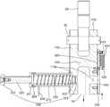
이하에서, 도 5 내지 도 7을 참조하여, 본 발명의 제2 실시 예를 설명하기로 한다. 도 5는 본 발명의 제2 실시 예를 따른 자동 풀림 샤클을 나타내는 측면도이고, 도 6은 도 5에 도시된 본 발명의 저면도이며, 도 7은 도 5에 도시된 본 발명의 작동상태도를 나타낸다.Hereinafter, a second embodiment of the present invention will be described with reference to FIGS. 5 to 7. 5 is a side view showing an automatic release shackle according to a second embodiment of the present invention, Figure 6 is a bottom view of the present invention shown in Figure 5, Figure 7 shows an operating state diagram of the present invention shown in FIG. .
본 발명의 제2실시 예는 샤클몸체(100), 체결수단(200), 잠금해제수단(300), 가이드부재(400), 인장스프링(500)으로 이루어질 수 있는데, 상기 샤클몸체, 잠금해제수단, 가이드부재, 인장스프링은 앞에서 설명한 내용과 대동소이하므로 상세한 설명은 생략하고 상기 체결수단에 대해서만 설명하기로 한다.The second embodiment of the present invention may be composed of the
상기 체결수단(200)은 체결핀(220), 압축스프링(230), 홀딩체(250)를 포함하여 구성될 수 있다.The fastening means 200 may be configured to include a
상기 체결핀(220)은 환봉 형상으로 이루어져 상기 지지부재(110)의 하부를 관통한다. 즉, 상기 지지부재(110)에 형성된 관통공(110a)들을 관통하여 양단부가 외부로 돌출될 수 있다.The
이때, 상기 체결핀(220)은 상기 관통공(110a)을 통해 출입 가능하도록 상기 체결핀(220)의 외경보다 상기 관통공(110a)의 내경이 더 길게 형성된다.In this case, the inner diameter of the through
그리고 상기 체결핀(220)의 일단에는 상기 관통공(110a)의 내경부다 더 긴 외경을 가지는 스토퍼(221)가 결합된다.One end of the
또한, 상기 체결핀(220)의 타단은 상기 잠금해제수단(300)에 걸리는 구조를 가지는데, 상기 체결핀(220)의 타단부는 상기 관통공(110a)을 관통하여 일부가 상기 지지부재(110)로부터 돌출되고, 돌출된 부분이 상기 잠금해제수단(300)에 걸리게 된다.In addition, the other end of the
이를 위해, 상기 체결핀(220)의 타단부에는 걸림홈(222)이 형성될 수 있다.To this end, a locking
상기 걸림홈(222)은 상기 체결핀(220)의 외경보다 짧은 외경을 가지며, 폭은 상기 잠금해제수단(300)의 두께보다 길게 형성된다.The locking
그리고 상기 체결핀(220)의 타단부는 가장자리 원주를 따라 테이퍼진 테이퍼부(223)가 형성된다. 상기 테이퍼부(223)는 외측으로 외경이 줄어드는 형상으로 이루어져 상기 잠금해제수단(300)에 삽입되는 것이 용이한 구조이다.And the other end of the
상기 압축스프링(230)은 상기 스토퍼(221)와 지지부재(110) 사이에 개재된다.The
이때, 상기 압축스프링(230)의 내경은 체결핀(220)의 외경보다 길고 상기 스토퍼(221)의 외경보다 짧게 형성되며, 상기 관통공(110a)보다 길게 형성되어 양단이 상기 지지부재(110)와 스토퍼(221)에 걸린 상태를 유지한다.At this time, the inner diameter of the
따라서, 상기 압축스프링(230)의 탄성력에 의해 상기 체결핀(220)은 상기 관통공으로부터 이탈되는 방향으로 힘을 받는다.Therefore, the
참고로 상기 압축스프링(230)의 탄성계수는 사람이 압축시킬 수 있을 정도의 적절한 탄성계수를 가질 수 있다.For reference, the elastic modulus of the
따라서, 상기 스토퍼(221)를 눌러 상기 체결핀(220)을 상기 관통공(110a)에 완전히 삽입시키고 단부가 상기 잠금해제수단(300)에 걸리게 하면, 도 5에 도시된 바와 같이 상기 압축스프링(230)은 탄성 압축된 상태로 고정된다.Accordingly, when the
한편, 어느 하나의 상기 지지부재(110)의 일측면에는 상기 체결핀(220)이 상기 압축스프링(230)에 의해 완전히 이탈되지 않도록 잡아주는 홀딩체(250)가 구비될 수 있다.On the other hand, one side of the supporting
상기 홀딩체(250)는 상기 지지부재(110)에 형성된 가이드 홀(251)에 삽입되어 상기 가이드 홀(251)의 내주면을 따라 왕복 가능하게 이동하는 슬라이더(252)와, 상기 가이드 홀(251)에 삽입되어 상기 슬라이더(252)를 탄성 지지하는 홀딩스프링(253)으로 구성된다The holding
여기서, 상기 가이드 홀(251)은 상기 지지부재(110)의 측면을 관통하여 상기 관통공(110a)과 연통된다. 그리고 홀딩스프링(253)은 압축스프링이다.Here, the
또 상기 슬라이더(252)의 폭은 상기 체결핀(220)의 걸림홈(222)의 폭보다 짧게 형성되어 상기 슬라이더(252)의 단부가 상기 걸림홈(222)에 인입될 수 있다. 그리고 상기 슬라이더(252)의 단부에는 경사면(252a)이 형성되는데, 상기 경사면(252a)은 상기 체결핀(220)이 후진하여 이탈하는 방향을 향하도록 형성된다.In addition, the width of the
따라서, 상기 체결핀(220)이 상기 잠금해제수단(300)으로부터 이탈하여 후진하더라도 상기 슬라이더(252)의 단부가 상기 홀딩스프링(253)의 탄성력에 의해 상승하면서 상기 걸림홈(222)에 걸리게 되어 상기 체결핀(220)은 상기 관통공(110a)으로부터 빠지지 않고 정지하게 된다.Therefore, even if the
이러한 작동상태는 도 7에 도시된 바와 같다.This operating state is as shown in FIG.
체결핀(220)을 잠그는 과정은 작업자가 중량물(미도시)에 형성된 후크(10)를 상기 샤클몸체(100)의 지지부재(110) 사이에 삽입시킨다. 즉, 양 지지부재(110)의 하부 사이에 삽입하여 후크(10)가 상기 관통공(110a)과 연통되도록 한다.In the process of locking the
이 상태에서 작업자가 상기 체결핀(220)을 밀어 상기 체결핀(220)을 전진시켜 후크(10)를 통과시킨다. 이때, 상기 압축스프링(230)은 압축되면서 상기 체결핀(220)은 전진하게 되고 단부는 상기 관통공(110a)을 관통하여 상기 잠금해제수단(300)에 도달하는데, 상기 체결핀(220)을 더 밀면 상기 체결핀(220)의 단부는 상기 체결공(330)을 통과한다.In this state, the operator pushes the
여기서, 상기 체결핀(220)이 전전할 때 상기 체결핀(220)의 걸림홈(222)에 삽입되어 있던 상기 슬라이더(252)는 경사면(252a)이 밀리면서 하강하게 된다. 즉, 상기 홀딩스프링(253)이 압축되면서 상기 슬라이더(252)는 상기 가이드 홀(251)을 따라 하강하여 대기한다.Here, the
그리고 상기 체결핀(220) 단부가 상기 체결공(330)을 통과할 때, 상기 잠금해제수단(300)은 약간 상승했다가 하강하여 상기 걸림홈(222)에 상기 걸림홀(332)이 안착되면서 상기 체결핀(220)은 고정되므로 빠지지 않게 된다.And when the end of the
다음으로 상기 체결핀(220)이 후크(10)로부터 자동으로 해제되는 과정을 설명한다.Next, the
크레인(미도시)으로 중량물을 필요한 곳에 내려놓으면 상기 샤클몸체(100)도 중량물의 상부면에 접촉하는데, 상기 지지부재(110)의 하단부가 중량물의 상부면에 접촉하기 전에 상기 잠금해제수단(300)의 하단부가 먼저 중량물의 상부면에 접촉하면서 상승하게 된다.When the heavy object is put down where necessary by a crane (not shown), the
그리고 상기 샤클몸체(100)의 무게 때문에 상기 인장스프링(500)이 늘어나면서 상기 잠금해제수단(300)이 밀려 올라간다.And because of the weight of the
상기 잠금해제수단(300)이 상승함에 따라 상기 걸림홀(332)도 상측으로 이동하게 되므로 상기 걸림홀(332)에 걸려 있던 상기 체결핀(220)의 단부는 상기 이탈홀(331)에 위치하는 순간 구속력이 제거되므로 상기 압축스프링(230)의 탄성력에 의해 상기 체결핀(220)은 즉각 후진하게 된다.As the locking release means 300 rises, the locking
그리고 상기 체결핀(220)이 후진하는 과정에서 상기 체결핀(220)에 걸려 있던 후크(10)는 자동으로 풀리게 된다.In addition, the
그런데 상기 체결핀(220)이 후진하다가 상기 걸림홈(222)이 상기 슬라이더(252)의 직 상방에 위치하는 순간 상기 홀딩스프링(253)이 팽창하면서 상기 슬라이더(252)를 밀어올리면 상기 슬라이더(252)의 단부가 상기 걸림홈(222)에 삽입되면서 걸리게 되어 상기 체결핀(220)은 더 이상 후진하지 않고 정지하게 된다.However, when the
이 상태에서 크레인으로 상기 샤클몸체(100)를 상승시키면 중량물과 샤클몸체(100)는 분리되며 상기 잠금해제수단(300)은 상기 인장스프링(500)에 의해 다시 하강하여 원위치 된다.In this state, ascending the
< 제3 실시 예>Third Embodiment
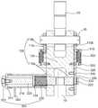
이하에서 도 8 내지 도 9를 참조하여 본 발명의 제3 실시 예를 설명한다. 도 8은 본 발명의 제3 실시 예를 따른 자동 풀림 샤클을 나타내는 측면도이고, 도 9는 도 8에 도시된 본 발명의 정면도이다.Hereinafter, a third embodiment of the present invention will be described with reference to FIGS. 8 to 9. 8 is a side view showing an automatic release shackle according to a third embodiment of the present invention, Figure 9 is a front view of the present invention shown in FIG.
본 발명의 또 다른 실시 예는 샤클몸체(100), 체결수단(200), 잠금해제수단(300), 가이드부재(400), 인장스프링(500)으로 구성되는데, 상기 체결수단과 가이드부재는 상술한 <제1 실시 예>의 설명과 대동소이하므로 설명은 생략하고, 상기 샤클몸체, 잠금해제수단, 인장스프링에 대해서 설명한다.Another embodiment of the present invention is composed of a
먼저, 상기 샤클몸체(100)는 상술한 바와 대동소이하게, 평판 형상의 동일한 두 지지부재(110)가 마주보도록 수직으로 배치되고 그 사이에 이음부재(120)가 구비되어 대략 단면이 'H' 형상을 가진다. 그리고 상기 샤클몸체(100)의 하부, 즉 상기 각 지지부재(110)의 하부에는 관통공(110a)이 형성된다.First, the
상기 샤클몸체(100)의 상부에는 크레인(미도시)과 연결되는 연결부재(20)가 연결핀(30)에 의해 핀 결합될 수 있다.A
또 상기 각 지지부재(110)의 상부에는 연결핀(30)이 관통하는 유격홀(110b)이 형성되는데, 상기 유격홀(110b)은 상하로 긴 형상의 홀이다. 따라서, 상기 연결핀(30)이 상기 유격홀(110b) 내에 수평으로 삽입된 상태에서 일정 거리만큼 상하로 움직일 수 있게 된다.In addition, a
다음으로 상기 잠금해제수단에 대해 설명한다.Next, the unlocking means will be described.
상기 잠금해제수단(300)은 상하로 긴 평판 형상을 이루고 전체적으로 상부가 넓고 하부가 상대적으로 좁은 형상으로서, 도시된 바와 같이 대략 화살표 형상일 수 있다. 즉, 상기 잠금해제수단(300) 상부에 양측으로 단턱(310)이 각각 형성된다.The unlocking means 300 forms a long flat plate shape up and down, and the upper portion is wide and the lower portion is relatively narrow, and may have an approximately arrow shape as shown. That is,
그리고 상기 잠금해제수단(300)의 상부에는 핀홀(340)이 형성되어 상기 연결핀(30)이 삽입되어 체결될 수 있다. 즉, 상기 연결핀(30)이 상하로 움직일 때 상기 잠금해제수단(300)도 상하로 움직일 수 있다.In addition, a pinhole 340 is formed at an upper portion of the unlocking means 300 so that the
또 상기 잠금해제수단(300)의 중앙에 상하로 긴 장공(320)이 형성된다. 상기 장공(320)의 길이는 상기 잠금해제수단(300)의 상하 이동거리와 동일하거나 좀 더 길도록 구비된다.In addition, the
또한, 상기 장공(320)의 하측에 체결공(330)이 형성된다. 상기 체결공(330)은 상기 체결핀(220)의 단부(타단부)가 통과하면서 걸릴 수 있는 구멍이다.In addition, a
상세하게는 상기 체결공(330)은 도시된 바와 같이 두 개의 홀이 중첩된 형상, 대략 튤립 형상이지만 앞의 <제1 실시 예>의 체결공을 뒤집어 놓은 것과 같다.In detail, the
상기 체결공(330)은 이탈홀(331)과 걸림홀(332)로 구성되며, 상기 이탈홀(331)이 상기 걸림홀(332)의 상측에 형성되도록 중첩된다.The
상기 이탈홀(331)은 상기 체결핀(220) 단부의 외경보다 더 긴 내경을 가져 상기 체결핀(220)이 자유롭게 출입할 수 있다. 바람직한 것은, 상기 체결공(330)의 좌우 폭은 상기 체결핀(220) 단부의 외경보다 길고, 상하 폭은 상기 장공(320)의 길이와 유사하게 형성되어 상기 잠금해제수단(300)의 상하 이동이 보장되어야 한다.The
그리고 상기 걸림홀(332)은 상기 체결핀(220)의 단부가 걸리도록 형성되는 것으로, 상기 체결핀(220)의 단부의 외경보다 더 짧은 내경을 가지며, 상기 이탈홀(331)과 중첩되어 도시된 바와 같이 원호로 형성된다.In addition, the locking
바람직하게는, 상기 걸림홀(332)은 상기 체결핀(220)에 형성된 걸림홈(222)의 외경와 동일하거나 약간 더 긴 내경을 가지도록 형성되어 상기 걸림홈(222)에 상기 걸림홀(332)이 걸리도록 할 수 있다. 즉, 상기 걸림홀(332)의 내주가 상기 걸림홈(222)에 안착되면서 상기 체결핀(220)의 단부가 상기 걸림홈(222)에 걸리게 된다.Preferably, the locking
한편, 상기 잠금해제수단(300)은 상기 지지부재(110)의 측면에 밀착된 상태로 상하로 슬라이딩 이동이 가능하게 구비된다. 이때, 상기 관통공(110a)은 상기 체결공(330)과 연통되도록 상기 잠금해제수단(300)이 배치되고, 상기 체결핀(220)이 상기 걸림홀(332)에 걸린 상태에서 상기 잠금해제수단(300)의 하단이 상기 지지부재(110)의 하단보다는 더 높이 위치하게 된다.On the other hand, the unlocking means 300 is provided to be capable of sliding up and down in close contact with the side of the
상기 인장스프링(500)은 상기 잠금해제수단(300)과 상기 지지부재(110)를 탄성적으로 연결한다.The
구체적으로 상기 인장스프링(500)의 상단은 상기 잠금해제수단(300)의 상부, 좀 더 자세하게, 상기 핀홀(340)과 장공(320) 사이에 고정된다. 이를 위해 상기 잠금해제수단(300)에 별도의 고정볼트(510)를 체결시킬 수 있다.Specifically, the upper end of the
그리고 상기 인장스프링(500)의 하단은 상기 지지부재(110)의 측면에 고정된다. 이를 위해 상기 지지부재(110)의 측면에 별도의 고정볼트(520)가 체결될 수 있는데, 상기 지지부재(110)에 체결된 고정볼트(520)는 상기 장공(320)을 통해 상기 잠금해제수단(300)을 통과하게 된다.And the lower end of the
따라서, 상기 잠금해제수단(300)이 상승하면 상기 인장스프링(500)은 늘어나고, 힘이 제거되면 상기 인장스프링(500)은 복귀되면서 상기 잠금해제수단(300)은 하강한다. 물론, 상기 지지부재(110)에 체결된 고정볼트(520)에 상기 장공(320)이 걸리면서 정지할 수 있다.Therefore, when the unlocking means 300 is raised, the
도 10을 참조하여 작동과정을 설명한다. 도 10은 도 8에 도시된 본 발명의 작동상태도를 나타낸다.An operation process will be described with reference to FIG. 10. 10 shows an operating state diagram of the present invention shown in FIG.
먼저, 후크(10)에 본 발명을 체결하는 과정을 설명한다.First, the process of fastening the present invention to the
최초, 상기 압축스프링(230)은 팽창된 상태이므로 상기 체결핀(220)은 상기 하우징(210)으로부터 완전히 인출된 상태이며 상기 체결핀(220)의 단부는 상기 하우징(210)이 결합된 지지부재(110)의 관통공(110a)까지 후진한 상태이다.First, since the
작업자는 크레인을 제어하여 상기 연결부재(20)를 약간 상승시키면, 상기 연결핀(30)은 상기 유격홀(110b)을 따라 일정 거리 상승하여 상기 유격홀(110b)의 상단 내주면에 걸리게 된다.When the operator controls the crane and slightly raises the
이때, 상기 연결핀(30)에 결합된 상기 잠금해제수단(300)도 함께 상승하고 상기 인장스프링(500)은 늘어난다. 이때, 상기 관통공(110a)과 상기 체결공(330)은 동일 중심선상에 위치한다.At this time, the unlocking means 300 coupled to the connecting
그리고 작업자는 중량물(미도시)에 형성된 후크(10)가 상기 샤클몸체(100)의 지지부재(110) 사이에 삽입시킨다. 즉, 양 지지부재(110)의 하부 사이에 삽입하여 후크(10)가 상기 관통공(110a)과 연통되도록 한다.And the worker inserts the
이 상태에서 작업자가 상기 체결핀(220)을 밀어 상기 체결핀(220)을 전진시켜 후크(10)를 통과시킨다. 이때, 상기 압축스프링(230)은 압축되면서 상기 체결핀(220)은 전진하게 되고 단부는 상기 관통공(110a)을 관통하여 상기 잠금해제수단(300)에 도달하는데, 상기 체결핀(220)을 더 밀면 상기 체결핀(220)의 단부는 상기 걸림홀(332)을 타고 넘어 상기 체결공(330)을 통과한다.In this state, the operator pushes the
상기 체결핀(220) 단부가 상기 체결공(330)을 통과할 때, 상기 잠금해제수단(300)은 약간 하강했다가 상승하여 상기 걸림홈(222)에 상기 걸림홀(332)이 안착되면서 상기 체결핀(220)은 고정되므로 빠지지 않게 된다.When the end of the
다음으로 상기 체결핀(220)이 후크(10)로부터 자동으로 해제되는 과정을 설명한다.Next, the
크레인(미도시)으로 중량물을 필요한 곳에 내려놓으면, 상기 샤클몸체(100)도 중량물의 상부면에 안착되고, 상기 인장스프링(500)의 인장력에 의해 상기 연결핀(30)도 상기 유격홀(110b) 내에서 하강하며, 상기 연결핀(30)에 결합된 상기 잠금해제수단(300)도 하강하게 된다.When the heavy weight is put down where necessary by the crane (not shown), the
상기 잠금해제수단(300)이 하강함에 따라 상기 걸림홀(332)도 하측으로 이동하게 되므로 상기 걸림홀(332)에 걸려 있던 상기 체결핀(220)의 단부는 상기 이탈홀(331)에 위치하는 순간 구속력이 제거되므로 상기 압축스프링(230)의 탄성력에 의해 상기 체결핀(220)은 즉각 후진하게 된다.As the locking release means 300 descends, the locking
도시된 바와 같이 체결핀(220)이 완전히 후진하면 상기 체결핀(220)에 걸려 있던 후크(10)는 자동으로 풀리게 된다.As shown in the drawing, when the
이 상태에서 크레인으로 상기 샤클몸체(100)를 상승시키면 중량물과 샤클몸체(100)는 분리된다.In this state, when lifting the
< 제4 실시 예>Fourth Embodiment
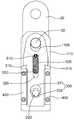
이하에서 도 11, 12를 참조하여 본 발명의 제4 실시 예를 설명한다. 도 11은 본 발명의 제4 실시 예를 따른 자동 풀림 샤클을 나타내는 측면도이고, 도 12는 도 11에 도시된 본 발명의 작동상태도를 나타낸다.Hereinafter, a fourth embodiment of the present invention will be described with reference to FIGS. 11 and 12. 11 is a side view showing an automatic release shackle according to a fourth embodiment of the present invention, Figure 12 is an operating state diagram of the present invention shown in FIG.
본 발명의 제4 실시 예도 샤클몸체(100), 체결수단(200), 잠금해제수단(300), 가이드부재(400), 인장스프링(500)으로 구성되는데, 다른 구성은 제3 실시 예와 대동소이하고 다만, 상기 체결수단의 구성에 있어서 차이가 있다.The fourth embodiment of the present invention also comprises a
그런데 본 발명의 제4 실시 예의 체결수단(200)도 체결핀(220), 압축스프링(230), 홀딩체(250)를 포함하여 구성될 수 있는데, 제2 실시 예에서 설명한 체결수단의 구성과 대동소이하므로 상세한 설명은 생략하고 작동과정을 설명한다.However, the fastening means 200 of the fourth embodiment of the present invention may also include a
먼저, 후크(10)에 본 발명을 체결하는 과정을 설명한다.First, the process of fastening the present invention to the
최초, 상기 압축스프링(230)은 팽창된 상태이므로 상기 체결핀(220)은 완전히 후진하여 인출된 상태이며 상기 체결핀(220)은 상기 홀딩체(250)에 걸려 정지된 상태이다.First, since the
작업자는 크레인을 제어하여 상기 연결부재(20)를 약간 상승시키면, 상기 연결핀(30)은 상기 유격홀(110b)을 따라 일정 거리 상승하여 상기 유격홀(110b)의 상단 내주면에 걸리게 된다.When the operator controls the crane and slightly raises the
이때, 상기 연결핀(30)에 결합된 상기 잠금해제수단(300)도 함께 상승하고 상기 인장스프링(500)은 늘어난다. 이때, 상기 관통공(110a)과 상기 체결공(330)은 동일 중심선상에 위치한다.At this time, the unlocking means 300 coupled to the connecting
작업자는 중량물(미도시)에 형성된 후크(10)가 상기 샤클몸체(100)의 지지부재(110) 사이에 삽입시킨다. 즉, 양 지지부재(110)의 하부 사이에 삽입하여 후크(10)가 상기 관통공(110a)과 연통되도록 한다.The worker inserts the
이 상태에서 작업자가 상기 체결핀(220)을 밀어 전진시켜 후크(10)를 통과시킨다. 이때, 상기 압축스프링(230)은 압축되고 상기 체결핀(220) 단부는 상기 관통공(110a)을 관통하여 상기 잠금해제수단(300)에 도달하는데, 상기 체결핀(220)을 더 밀면 상기 체결핀(220)의 단부는 상기 걸림홀(332)을 타고 넘어 상기 체결공(330)을 통과한다.In this state, the operator pushes the
상기 체결핀(220) 단부가 상기 체결공(330)을 통과할 때, 상기 잠금해제수단(300)은 약간 하강했다가 상승하여 상기 걸림홈(222)에 상기 걸림홀(332)이 안착되면서 상기 체결핀(220)은 고정되므로 빠지지 않게 된다.When the end of the
다음으로 상기 체결핀(220)이 후크(10)로부터 자동으로 해제되는 과정을 설명한다.Next, the
크레인(미도시)으로 중량물을 필요한 곳에 내려놓으면, 상기 샤클몸체(100)도 중량물의 상부면에 안착되고, 상기 인장스프링(500)의 인장력에 의해 상기 연결핀(30)도 상기 유격홀(110b) 내에서 하강하며, 상기 연결핀(30)에 결합된 상기 잠금해제수단(300)도 하강하게 된다.When the heavy weight is put down where necessary by a crane (not shown), the
상기 잠금해제수단(300)이 하강함에 따라 상기 걸림홀(332)도 하측으로 이동하게 되므로 상기 걸림홀(332)에 걸려 있던 상기 체결핀(220)의 단부는 상기 이탈홀(331)에 위치하는 순간 구속력이 제거되므로 상기 압축스프링(230)의 탄성력에 의해 상기 체결핀(220)은 즉각 후진하게 된다.As the locking release means 300 descends, the locking
도시된 바와 같이 체결핀(220)이 후진하는 과정에서 상기 체결핀(220)에 걸려 있던 후크(10)는 자동으로 풀리게 된다.As shown in the drawing, the
그런데 상기 체결핀(220)이 후진하다가 상기 걸림홈(222)이 상기 슬라이더(252)의 직 상방에 위치하는 순간 상기 홀딩스프링(253)이 팽창하면서 상기 슬라이더(252)를 밀어올리면 상기 슬라이더(252)의 단부가 상기 걸림홈(222)에 삽입되면서 걸리게 되어 상기 체결핀(220)은 더 이상 후진하지 않고 정지하게 된다.However, when the
이 상태에서 크레인으로 상기 샤클몸체(100)를 상승시키면 중량물과 샤클몸체(100)는 분리된다.In this state, when lifting the
이상에서 도면을 참조하여 본 발명의 대표적인 실시 예를 설명하였지만, 본 발명이 속한 분야에서 통상의 지식을 가진 자라면 상기 내용을 바탕으로 본 발명의 범주 내에서 다양한 응용 및 변형을 행하는 것이 가능할 것이다. 그러므로 본 발명의 권리범위는 설명된 실시 예에 국한되어 정해져서는 안되며, 후술하는 특허청구범위뿐만 아니라 이 특허청구범위와 균등한 것들에 의해 정해져야 한다.Although the exemplary embodiments of the present invention have been described above with reference to the drawings, those skilled in the art will be able to perform various applications and modifications within the scope of the present invention based on the above contents. Therefore, the scope of the present invention should not be limited to the embodiments described, but should be defined by the claims below and equivalents thereof.
100 : 샤클몸체
110 : 지지부재110a : 관통공
110b : 유격홀120 : 이음부재
200 : 체결수단210 : 하우징
211 : 캡211a : 캡홀
220 : 체결핀221 : 스토퍼
222 : 걸림홈223 : 테이퍼부
224 : 리브230 : 압축스프링
240 : 받침부재250 : 홀딩체
251 : 가이드 홀252 : 슬라이더
252a : 경사면253 : 홀딩스프링
300 : 잠금해제수단
310 : 단턱320 : 장공
330 : 체결공331 : 이탈홀
332 : 걸림홀340 : 핀홀
400 : 가이드부재
500 : 인장스프링510, 520 : 고정볼트
10 : 후크20 : 연결부재
30 : 연결핀100: shackle body
110:
110b: play hole 120: joint member
200: fastening means 210: housing
211: cap 211a: cap hole
220: fastening pin 221: stopper
222: locking groove 223: tapered portion
224: rib 230: compression spring
240: support member 250: holding body
251: guide hole 252: slider
252a: slope 253: holding spring
300: unlocking means
310: step 320: long hole
330: fastening hole 331: release hole
332: locking hole 340: pin hole
400: guide member
500:
10: hook 20: connecting member
30: connecting pin
Claims (12)
Translated fromKorean평판 형상이고 상호 마주보는 한 쌍의 지지부재와 상기 지지부재를 서로 이격되게 연결하는 이음부재로 이루어져 단면이 'H' 형상으로 이루어지는 샤클몸체;
상기 후크가 걸리도록 상기 양 지지부재의 하부를 관통하되, 탄성 압축된 상태로 고정되는 체결수단;
평판 형상으로 이루어지고, 양측에 하기 가이드 부재에 걸릴 수 있는 단턱이 형성되며, 중앙에 상하로 긴 장공이 형성되고, 상기 장공의 하측에 상기 체결수단의 단부가 통과하여 걸릴 수 있는 체결공이 형성되어, 상기 지지부재의 측면에 밀착된 상태로 상하 슬라이딩 가능하게 움직이는 잠금해제수단;
상기 잠금해제수단의 양측으로 구비되어 상기 잠금해제수단의 상하 슬라이딩을 안내하는 가이드부재; 및
상기 장공을 통해 상기 지지부재와 상기 잠금해제수단의 상단을 연결하는 인장스프링;을 포함하여 이루어져,
상기 샤클몸체가 중량물 상부면과 접촉하면 상기 잠금해제수단이 밀려 상승하여 상기 체결수단의 단부가 이탈하면서 잠금상태가 해제되는 것을 특징으로 하는 자동 풀림 샤클.In the shackle connecting the heavy hook and the crane,
A shackle body having a flat plate shape and a pair of support members facing each other and a joint member connecting the support members to be spaced apart from each other;
Fastening means penetrating the lower portions of the support members so that the hooks are caught and fixed in an elastically compressed state;
It is formed in a flat plate shape, the stepped portion is formed on both sides to be caught by the following guide member, the long hole is formed up and down in the center, and the fastening hole which is formed through the end of the fastening means is formed in the lower side of the long hole Locking means for sliding up and down sliding in close contact with the side of the support member;
Guide members provided on both sides of the unlocking means to guide the vertical sliding of the unlocking means; And
It comprises; a tension spring for connecting the upper end of the support member and the unlocking means through the long hole;
When the shackle body is in contact with the upper surface of the heavy object, the unlocking means is pushed up and the end of the fastening means is released, the automatic unlocking shackle, characterized in that the release.
상기 체결수단은,
상기 지지부재 중 어느 하나의 하부 측면에 수직으로 결합되는 중공 형상의 하우징;
봉 형상으로 이루어져 일측은 상기 하우징 내에 수용되고 타측은 상기 각 지지부재의 하부를 관통하여 돌출되며, 일단은 상기 하우징의 단부에 걸리고 타단은 상기 잠금해제수단에 걸리며, 중간에 돌출된 리브가 형성되는 체결핀;
상기 하우징 내에서 상기 리브와 지지부재의 사이에 탄성적으로 수용되는 압축스프링;을 포함하여 이루어지는 것을 특징으로 하는 자동 풀림 샤클.The method of claim 1,
The fastening means,
A housing having a hollow shape vertically coupled to a lower side of any one of the supporting members;
Consists of a rod shape, one side is received in the housing and the other side is protruded through the lower portion of each support member, one end is caught by the end of the housing and the other end is caught by the unlocking means, the fastening rib is formed in the middle pin;
And a compression spring resiliently received between the rib and the support member in the housing.
상기 체결핀의 타단에는 상기 체결핀의 외경보다 짧은 외경을 가지는 걸림홈이 형성되는 것을 특징으로 하는 자동 풀림 샤클.The method of claim 2,
The other end of the fastening pin is an automatic release shackle, characterized in that the engaging groove having an outer diameter shorter than the outer diameter of the fastening pin is formed.
상기 체결수단은,
봉 형상으로 이루어져 상기 각 지지부재의 하부를 관통하되, 일단에는 스토퍼가 형성되고 타단에는 상기 잠금해제수단에 걸리도록 걸림홈이 형성되는 체결핀;
상기 스토퍼와 일측 지지부재 사이에 탄성적으로 게재되는 압축스프링;
상기 일측 지지부재에 형성되어 상기 압축스프링에 의해 후진하는 상기 체결핀의 걸림홈에 걸리게 함으로써 상기 체결핀을 잡아주는 홀딩체;를 포함하여 이루어지는 것을 특징으로 하는 자동 풀림 샤클.The method of claim 1,
The fastening means,
A fastening pin having a rod shape and penetrating a lower portion of each of the supporting members, and having a stopper formed at one end thereof and a locking groove formed at the other end thereof to be locked by the unlocking means;
A compression spring elastically placed between the stopper and one side support member;
And a holding body formed on the one side support member and holding the fastening pin by engaging the locking groove of the fastening pin retracted by the compression spring.
상기 홀딩체는,
상기 지지부재의 측면에 관통, 형성되는 가이드 홀에 삽입되고 단부에 경사면이 형성된 슬라이더와, 상기 가이드 홀에 삽입되어 상기 슬라이더를 탄성 지지하는 홀딩스프링으로 구성되는 것을 특징으로 하는 자동 풀림 샤클.The method of claim 4, wherein
The holding body,
And a slider inserted in the guide hole penetrating and formed in the side surface of the support member and having an inclined surface at an end thereof, and a holding spring inserted into the guide hole to elastically support the slider.
상기 체결공은,
상기 체결수단 단부의 외경보다 더 긴 내경을 가지는 이탈홀과, 상기 체결수단의 단부가 걸리도록 상기 체결수단 단부의 외경보다 짧은 내경을 가지는 걸림홀이 서로 중첩되되,
상기 걸림홀이 상기 이탈홀의 상측에 형성되도록 중첩되는 것을 특징으로 하는 자동 풀림 샤클.The method of claim 1,
The fastening hole,
A separation hole having an inner diameter longer than the outer diameter of the fastening means end and the engaging hole having an inner diameter shorter than the outer diameter of the fastening means end so that the end of the fastening means is overlapped with each other,
Automatic release shackle, characterized in that the engaging hole is overlapped to be formed on the upper side of the separation hole.
평판 형상이고 상부에 연결핀이 관통하도록 상하로 긴 유격홀이 형성되며 상호 마주보는 한 쌍의 지지부재와, 상기 지지부재를 서로 이격되게 연결하는 이음부재로 이루어져 단면이 'H' 형상으로 이루어지는 샤클몸체;
상기 후크가 걸리도록 상기 양 지지부재의 하부를 관통하되, 탄성 압축된 상태로 고정되는 체결수단;
상부가 상기 연결핀 일단에 결합되고, 상기 지지부재의 측면에 밀착되어 상하 슬라이딩 가능하게 움직이며, 하부에 상기 체결수단의 단부가 걸리고, 중앙에 장공이 형성된 잠금해제수단;
상기 잠금해제수단의 양측으로 구비되어 상기 잠금해제수단의 상하 슬라이딩을 안내하는 가이드부재; 및
상기 장공을 통해 상기 지지부재와 상기 잠금해제수단의 상단을 연결하는 인장스프링;을 포함하여 이루어져,
상기 샤클몸체가 중량물 상부면과 접촉하면 상기 연결핀의 하강과 함께 상기 잠금해제수단이 하강하여 상기 체결수단의 단부가 이탈하면서 잠금상태가 해제되는 것을 특징으로 하는 자동 풀림 샤클.In the shackle connecting the heavy hook and the crane,
Shackle consisting of a flat plate shape and a long clearance hole is formed up and down so that the connecting pin penetrates at the top, and a pair of support members facing each other, and a joint member connecting the support members spaced apart from each other, the cross section is formed in the 'H' shape Body;
Fastening means penetrating the lower portions of the support members so that the hooks are caught and fixed in an elastically compressed state;
An upper end coupled to one end of the connecting pin, the upper end sliding in close contact with the side of the support member, the lower end of the fastening means being caught, and an unlocking means having a long hole in the center;
Guide members provided on both sides of the unlocking means to guide the vertical sliding of the unlocking means; And
It comprises; a tension spring for connecting the upper end of the support member and the unlocking means through the long hole;
When the shackle body is in contact with the upper surface of the heavy object, the automatic release shackle, characterized in that the unlocking means is lowered with the lowering of the connection pin is released and the end of the fastening means is released while the locked state is released.
상기 체결수단은,
상기 지지부재 중 어느 하나의 하부 측면에 수직으로 결합되는 중공 형상의 하우징;
봉 형상으로 이루어져 일측은 상기 하우징 내에 수용되고 타측은 상기 각 지지부재의 하부를 관통하여 돌출되며, 일단은 상기 하우징의 단부에 걸리고 타단은 상기 잠금해제수단에 걸리며, 중간에 돌출된 리브가 형성되는 체결핀;
상기 하우징 내에서 상기 리브와 지지부재의 사이에 탄성적으로 수용되는 압축스프링;을 포함하여 이루어지는 것을 특징으로 하는 자동 풀림 샤클.The method of claim 8,
The fastening means,
A housing having a hollow shape vertically coupled to a lower side of any one of the supporting members;
Consists of a rod shape, one side is received in the housing and the other side is protruded through the lower portion of each support member, one end is caught by the end of the housing and the other end is caught by the unlocking means, the fastening rib is formed in the middle pin;
And a compression spring resiliently received between the rib and the support member in the housing.
상기 체결수단은,
봉 형상으로 이루어져 상기 각 지지부재의 하부를 관통하되, 일단에는 스토퍼가 형성되고 타단에는 상기 잠금해제수단에 걸리도록 걸림홈이 형성되는 체결핀;
상기 스토퍼와 일측 지지부재 사이에 탄성적으로 게재되는 압축스프링;
상기 일측 지지부재에 형성되어 상기 압축스프링에 의해 후진하는 상기 체결핀의 걸림홈에 걸리게 함으로써 상기 체결핀을 잡아주는 홀딩체;를 포함하여 이루어지는 것을 특징으로 하는 자동 풀림 샤클.The method of claim 8,
The fastening means,
A fastening pin having a rod shape and penetrating a lower portion of each of the supporting members, and having a stopper formed at one end thereof and a locking groove formed at the other end thereof to be locked by the unlocking means;
A compression spring elastically placed between the stopper and one side support member;
And a holding body formed on the one side support member and holding the fastening pin by engaging the locking groove of the fastening pin retracted by the compression spring.
상기 잠금해제수단은,
평판 형상으로 이루어지고, 양측에 상기 가이드 부재에 걸릴 수 있는 단턱이 형성되며, 상부에 상기 연결핀이 관통하는 핀홀이 형성되고, 중앙에 상하로 긴 장공이 형성되며, 상기 장공의 하측에 상기 체결수단의 단부가 통과하여 걸릴 수 있는 체결공이 형성되는 것을 특징으로 하는 자동 풀림 샤클.The method of claim 8,
The unlocking means,
It is formed in a flat plate shape, the stepped to the hook member is formed on both sides, a pinhole through which the connecting pin penetrates is formed in the upper, the long hole is formed in the center up and down, the fastening to the lower side of the long hole An automatic release shackle, characterized in that a fastening hole is formed through which the end of the means can be caught.
상기 체결공은,
상기 체결수단 단부의 외경보다 더 긴 내경을 가지는 이탈홀과, 상기 체결수단의 단부가 걸리도록 상기 체결수단 단부의 외경보다 짧은 내경을 가지는 걸림홀이 서로 중첩되되,
상기 이탈홀이 상기 걸림홀의 상측에 형성되도록 중첩되는 것을 특징으로 하는 자동 풀림 샤클.The method of claim 11,
The fastening hole,
A separation hole having an inner diameter longer than the outer diameter of the fastening means end and the engaging hole having an inner diameter shorter than the outer diameter of the fastening means end so that the end of the fastening means is overlapped with each other,
Automatic release shackle, characterized in that the separation hole is overlapped to be formed on the upper side of the engaging hole.
Priority Applications (1)
| Application Number | Priority Date | Filing Date | Title |
|---|---|---|---|
| KR1020180074347AKR102051669B1 (en) | 2018-06-27 | 2018-06-27 | Automated unlocking shackle |
Applications Claiming Priority (1)
| Application Number | Priority Date | Filing Date | Title |
|---|---|---|---|
| KR1020180074347AKR102051669B1 (en) | 2018-06-27 | 2018-06-27 | Automated unlocking shackle |
Publications (1)
| Publication Number | Publication Date |
|---|---|
| KR102051669B1true KR102051669B1 (en) | 2020-01-08 |
Family
ID=69154126
Family Applications (1)
| Application Number | Title | Priority Date | Filing Date |
|---|---|---|---|
| KR1020180074347AExpired - Fee RelatedKR102051669B1 (en) | 2018-06-27 | 2018-06-27 | Automated unlocking shackle |
Country Status (1)
| Country | Link |
|---|---|
| KR (1) | KR102051669B1 (en) |
Cited By (9)
| Publication number | Priority date | Publication date | Assignee | Title |
|---|---|---|---|---|
| CN111495802A (en)* | 2020-04-22 | 2020-08-07 | 河南中烟工业有限责任公司 | Manual push type dust removing device |
| KR102201892B1 (en)* | 2020-02-13 | 2021-01-12 | 주식회사 대성지티 | One-touch micro movement and movement prevention device of moving body |
| KR20220000536U (en)* | 2020-08-26 | 2022-03-07 | 주식회사 한국가스기술공사 | Flexible angle type shackle structure |
| CN114751296A (en)* | 2022-06-14 | 2022-07-15 | 杭州未名信科科技有限公司 | A tower crane intelligent spreader and its electric unlocking rope control method |
| CN116691459A (en)* | 2023-06-12 | 2023-09-05 | 安百拓(张家口)建筑矿山设备有限公司 | Rock drilling jumbo, cockpit and seating device thereof |
| CN116729214A (en)* | 2023-08-10 | 2023-09-12 | 山东天河科技股份有限公司 | Colliery hydraulic pressure stock drill carriage |
| KR20240006280A (en)* | 2022-07-06 | 2024-01-15 | 주식회사 이지락 | Safety shackle |
| KR20240006281A (en)* | 2022-07-06 | 2024-01-15 | 주식회사 이지락 | Safety shackle |
| CN120062309A (en)* | 2025-04-27 | 2025-05-30 | 北京建工集团有限责任公司 | Unhooking-free lifting tool |
Citations (7)
| Publication number | Priority date | Publication date | Assignee | Title |
|---|---|---|---|---|
| JPS6146978U (en)* | 1984-08-29 | 1986-03-28 | 象印チエンブロツク株式会社 | Shackle |
| KR20080000757A (en) | 2006-06-28 | 2008-01-03 | 홍제윤 | Shackle assembly |
| KR20090011746A (en) | 2007-07-27 | 2009-02-02 | 주식회사 피엔에이치 | Safety device of self-opening shackle assembly |
| KR100891101B1 (en)* | 2007-10-31 | 2009-03-30 | 주식회사 피엔에이치 | Auto Open Shackle Assembly |
| KR200478395Y1 (en) | 2015-03-26 | 2015-09-30 | 최태진 | Screw bolt loose anti-reverse shackle |
| KR20170010748A (en) | 2014-03-10 | 2017-02-01 | 코네크레인스 글로벌 코포레이션 | Lifting hook, safety latch of lifting hook and locking and releasing device of safety latch |
| KR101776869B1 (en) | 2014-12-23 | 2017-09-14 | 주식회사 아인디자인 | Semi-automatic shackle |
- 2018
- 2018-06-27KRKR1020180074347Apatent/KR102051669B1/ennot_activeExpired - Fee Related
Patent Citations (7)
| Publication number | Priority date | Publication date | Assignee | Title |
|---|---|---|---|---|
| JPS6146978U (en)* | 1984-08-29 | 1986-03-28 | 象印チエンブロツク株式会社 | Shackle |
| KR20080000757A (en) | 2006-06-28 | 2008-01-03 | 홍제윤 | Shackle assembly |
| KR20090011746A (en) | 2007-07-27 | 2009-02-02 | 주식회사 피엔에이치 | Safety device of self-opening shackle assembly |
| KR100891101B1 (en)* | 2007-10-31 | 2009-03-30 | 주식회사 피엔에이치 | Auto Open Shackle Assembly |
| KR20170010748A (en) | 2014-03-10 | 2017-02-01 | 코네크레인스 글로벌 코포레이션 | Lifting hook, safety latch of lifting hook and locking and releasing device of safety latch |
| KR101776869B1 (en) | 2014-12-23 | 2017-09-14 | 주식회사 아인디자인 | Semi-automatic shackle |
| KR200478395Y1 (en) | 2015-03-26 | 2015-09-30 | 최태진 | Screw bolt loose anti-reverse shackle |
Cited By (13)
| Publication number | Priority date | Publication date | Assignee | Title |
|---|---|---|---|---|
| KR102201892B1 (en)* | 2020-02-13 | 2021-01-12 | 주식회사 대성지티 | One-touch micro movement and movement prevention device of moving body |
| CN111495802A (en)* | 2020-04-22 | 2020-08-07 | 河南中烟工业有限责任公司 | Manual push type dust removing device |
| KR20220000536U (en)* | 2020-08-26 | 2022-03-07 | 주식회사 한국가스기술공사 | Flexible angle type shackle structure |
| KR200496065Y1 (en)* | 2020-08-26 | 2022-10-26 | 주식회사 한국가스기술공사 | Flexible angle type shackle structure |
| CN114751296A (en)* | 2022-06-14 | 2022-07-15 | 杭州未名信科科技有限公司 | A tower crane intelligent spreader and its electric unlocking rope control method |
| KR102743006B1 (en)* | 2022-07-06 | 2024-12-16 | 주식회사 이지락 | Safety shackle |
| KR20240006280A (en)* | 2022-07-06 | 2024-01-15 | 주식회사 이지락 | Safety shackle |
| KR20240006281A (en)* | 2022-07-06 | 2024-01-15 | 주식회사 이지락 | Safety shackle |
| KR102743004B1 (en)* | 2022-07-06 | 2024-12-16 | 주식회사 이지락 | Safety shackle |
| US12331810B2 (en) | 2022-07-06 | 2025-06-17 | Easy Lock Co., Ltd. | Safety shackle |
| CN116691459A (en)* | 2023-06-12 | 2023-09-05 | 安百拓(张家口)建筑矿山设备有限公司 | Rock drilling jumbo, cockpit and seating device thereof |
| CN116729214A (en)* | 2023-08-10 | 2023-09-12 | 山东天河科技股份有限公司 | Colliery hydraulic pressure stock drill carriage |
| CN120062309A (en)* | 2025-04-27 | 2025-05-30 | 北京建工集团有限责任公司 | Unhooking-free lifting tool |
Similar Documents
| Publication | Publication Date | Title |
|---|---|---|
| KR102051669B1 (en) | Automated unlocking shackle | |
| KR100432776B1 (en) | Scaffold joint | |
| KR101960059B1 (en) | Safety device for fall prevention of steel tower | |
| US3033605A (en) | Expansion-type grapple for lifting and carrying loads | |
| US3307871A (en) | Toggle device for lifting heavy objects | |
| US10577225B1 (en) | Adjustable spreader bar | |
| US4398762A (en) | Pickup device for lifting concrete body | |
| CN112390143B (en) | Hanging device and lifting equipment | |
| KR20170076033A (en) | Device for fling pile | |
| CA2809684A1 (en) | Chain hook | |
| KR20180043516A (en) | Transporting clamp for reinforced block | |
| KR20150061147A (en) | Drawbar hook for quick coupler | |
| US3051521A (en) | Automatically releasing lifting tongs | |
| US2895430A (en) | Freight securing means | |
| US20060087137A1 (en) | Remote release apparatus and method for lifting and releasing a load | |
| US3239265A (en) | Cargo pallet sling | |
| US7134701B1 (en) | Frame for lifting beams and other elongated loads | |
| KR101976378B1 (en) | Shackle having a structural stability | |
| KR100974255B1 (en) | semi automatic hook apparatus using pulling a heavy load | |
| KR101211037B1 (en) | Hanger anchor of work scaffold | |
| KR101954885B1 (en) | Slide-type carrier for motorcycle | |
| US2815556A (en) | Safety belt clamp | |
| US3331334A (en) | Stake pocket chain anchor | |
| KR102677144B1 (en) | Apparatus for latching the hoist crane | |
| KR102121924B1 (en) | Brake apparatus of over head crane |
Legal Events
| Date | Code | Title | Description |
|---|---|---|---|
| PA0109 | Patent application | St.27 status event code:A-0-1-A10-A12-nap-PA0109 | |
| PA0201 | Request for examination | St.27 status event code:A-1-2-D10-D11-exm-PA0201 | |
| D13-X000 | Search requested | St.27 status event code:A-1-2-D10-D13-srh-X000 | |
| D14-X000 | Search report completed | St.27 status event code:A-1-2-D10-D14-srh-X000 | |
| PE0902 | Notice of grounds for rejection | St.27 status event code:A-1-2-D10-D21-exm-PE0902 | |
| E13-X000 | Pre-grant limitation requested | St.27 status event code:A-2-3-E10-E13-lim-X000 | |
| P11-X000 | Amendment of application requested | St.27 status event code:A-2-2-P10-P11-nap-X000 | |
| P13-X000 | Application amended | St.27 status event code:A-2-2-P10-P13-nap-X000 | |
| PE0701 | Decision of registration | St.27 status event code:A-1-2-D10-D22-exm-PE0701 | |
| GRNT | Written decision to grant | ||
| PR0701 | Registration of establishment | St.27 status event code:A-2-4-F10-F11-exm-PR0701 | |
| PR1002 | Payment of registration fee | St.27 status event code:A-2-2-U10-U11-oth-PR1002 Fee payment year number:1 | |
| PG1601 | Publication of registration | St.27 status event code:A-4-4-Q10-Q13-nap-PG1601 | |
| PR1001 | Payment of annual fee | St.27 status event code:A-4-4-U10-U11-oth-PR1001 Fee payment year number:4 | |
| R18-X000 | Changes to party contact information recorded | St.27 status event code:A-5-5-R10-R18-oth-X000 | |
| R18-X000 | Changes to party contact information recorded | St.27 status event code:A-5-5-R10-R18-oth-X000 | |
| PC1903 | Unpaid annual fee | St.27 status event code:A-4-4-U10-U13-oth-PC1903 Not in force date:20231128 Payment event data comment text:Termination Category : DEFAULT_OF_REGISTRATION_FEE | |
| R18-X000 | Changes to party contact information recorded | St.27 status event code:A-5-5-R10-R18-oth-X000 | |
| PC1903 | Unpaid annual fee | St.27 status event code:N-4-6-H10-H13-oth-PC1903 Ip right cessation event data comment text:Termination Category : DEFAULT_OF_REGISTRATION_FEE Not in force date:20231128 |