KR102051096B1 - 2-stage scroll compressor and refrigerating cycle system having the same - Google Patents
2-stage scroll compressor and refrigerating cycle system having the sameDownload PDFInfo
- Publication number
- KR102051096B1 KR102051096B1KR1020130079883AKR20130079883AKR102051096B1KR 102051096 B1KR102051096 B1KR 102051096B1KR 1020130079883 AKR1020130079883 AKR 1020130079883AKR 20130079883 AKR20130079883 AKR 20130079883AKR 102051096 B1KR102051096 B1KR 102051096B1
- Authority
- KR
- South Korea
- Prior art keywords
- scroll
- primary
- fixed
- compression chamber
- wrap
- Prior art date
- Legal status (The legal status is an assumption and is not a legal conclusion. Google has not performed a legal analysis and makes no representation as to the accuracy of the status listed.)
- Expired - Fee Related
Links
Images


Classifications
- F—MECHANICAL ENGINEERING; LIGHTING; HEATING; WEAPONS; BLASTING
- F04—POSITIVE - DISPLACEMENT MACHINES FOR LIQUIDS; PUMPS FOR LIQUIDS OR ELASTIC FLUIDS
- F04C—ROTARY-PISTON, OR OSCILLATING-PISTON, POSITIVE-DISPLACEMENT MACHINES FOR LIQUIDS; ROTARY-PISTON, OR OSCILLATING-PISTON, POSITIVE-DISPLACEMENT PUMPS
- F04C18/00—Rotary-piston pumps specially adapted for elastic fluids
- F04C18/02—Rotary-piston pumps specially adapted for elastic fluids of arcuate-engagement type, i.e. with circular translatory movement of co-operating members, each member having the same number of teeth or tooth-equivalents
- F04C18/0207—Rotary-piston pumps specially adapted for elastic fluids of arcuate-engagement type, i.e. with circular translatory movement of co-operating members, each member having the same number of teeth or tooth-equivalents both members having co-operating elements in spiral form
- F04C18/0215—Rotary-piston pumps specially adapted for elastic fluids of arcuate-engagement type, i.e. with circular translatory movement of co-operating members, each member having the same number of teeth or tooth-equivalents both members having co-operating elements in spiral form where only one member is moving
- F—MECHANICAL ENGINEERING; LIGHTING; HEATING; WEAPONS; BLASTING
- F04—POSITIVE - DISPLACEMENT MACHINES FOR LIQUIDS; PUMPS FOR LIQUIDS OR ELASTIC FLUIDS
- F04C—ROTARY-PISTON, OR OSCILLATING-PISTON, POSITIVE-DISPLACEMENT MACHINES FOR LIQUIDS; ROTARY-PISTON, OR OSCILLATING-PISTON, POSITIVE-DISPLACEMENT PUMPS
- F04C23/00—Combinations of two or more pumps, each being of rotary-piston or oscillating-piston type, specially adapted for elastic fluids; Pumping installations specially adapted for elastic fluids; Multi-stage pumps specially adapted for elastic fluids
- F04C23/001—Combinations of two or more pumps, each being of rotary-piston or oscillating-piston type, specially adapted for elastic fluids; Pumping installations specially adapted for elastic fluids; Multi-stage pumps specially adapted for elastic fluids of similar working principle
- F—MECHANICAL ENGINEERING; LIGHTING; HEATING; WEAPONS; BLASTING
- F04—POSITIVE - DISPLACEMENT MACHINES FOR LIQUIDS; PUMPS FOR LIQUIDS OR ELASTIC FLUIDS
- F04C—ROTARY-PISTON, OR OSCILLATING-PISTON, POSITIVE-DISPLACEMENT MACHINES FOR LIQUIDS; ROTARY-PISTON, OR OSCILLATING-PISTON, POSITIVE-DISPLACEMENT PUMPS
- F04C23/00—Combinations of two or more pumps, each being of rotary-piston or oscillating-piston type, specially adapted for elastic fluids; Pumping installations specially adapted for elastic fluids; Multi-stage pumps specially adapted for elastic fluids
- F04C23/008—Hermetic pumps
- F—MECHANICAL ENGINEERING; LIGHTING; HEATING; WEAPONS; BLASTING
- F04—POSITIVE - DISPLACEMENT MACHINES FOR LIQUIDS; PUMPS FOR LIQUIDS OR ELASTIC FLUIDS
- F04C—ROTARY-PISTON, OR OSCILLATING-PISTON, POSITIVE-DISPLACEMENT MACHINES FOR LIQUIDS; ROTARY-PISTON, OR OSCILLATING-PISTON, POSITIVE-DISPLACEMENT PUMPS
- F04C29/00—Component parts, details or accessories of pumps or pumping installations, not provided for in groups F04C18/00 - F04C28/00
- F04C29/0021—Systems for the equilibration of forces acting on the pump
- F04C29/0035—Equalization of pressure pulses
- F—MECHANICAL ENGINEERING; LIGHTING; HEATING; WEAPONS; BLASTING
- F04—POSITIVE - DISPLACEMENT MACHINES FOR LIQUIDS; PUMPS FOR LIQUIDS OR ELASTIC FLUIDS
- F04C—ROTARY-PISTON, OR OSCILLATING-PISTON, POSITIVE-DISPLACEMENT MACHINES FOR LIQUIDS; ROTARY-PISTON, OR OSCILLATING-PISTON, POSITIVE-DISPLACEMENT PUMPS
- F04C29/00—Component parts, details or accessories of pumps or pumping installations, not provided for in groups F04C18/00 - F04C28/00
- F04C29/02—Lubrication; Lubricant separation
- F04C29/028—Means for improving or restricting lubricant flow
- F—MECHANICAL ENGINEERING; LIGHTING; HEATING; WEAPONS; BLASTING
- F04—POSITIVE - DISPLACEMENT MACHINES FOR LIQUIDS; PUMPS FOR LIQUIDS OR ELASTIC FLUIDS
- F04C—ROTARY-PISTON, OR OSCILLATING-PISTON, POSITIVE-DISPLACEMENT MACHINES FOR LIQUIDS; ROTARY-PISTON, OR OSCILLATING-PISTON, POSITIVE-DISPLACEMENT PUMPS
- F04C2210/00—Fluid
- F04C2210/26—Refrigerants with particular properties, e.g. HFC-134a
- F—MECHANICAL ENGINEERING; LIGHTING; HEATING; WEAPONS; BLASTING
- F04—POSITIVE - DISPLACEMENT MACHINES FOR LIQUIDS; PUMPS FOR LIQUIDS OR ELASTIC FLUIDS
- F04C—ROTARY-PISTON, OR OSCILLATING-PISTON, POSITIVE-DISPLACEMENT MACHINES FOR LIQUIDS; ROTARY-PISTON, OR OSCILLATING-PISTON, POSITIVE-DISPLACEMENT PUMPS
- F04C2240/00—Components
- F04C2240/40—Electric motor
- Y—GENERAL TAGGING OF NEW TECHNOLOGICAL DEVELOPMENTS; GENERAL TAGGING OF CROSS-SECTIONAL TECHNOLOGIES SPANNING OVER SEVERAL SECTIONS OF THE IPC; TECHNICAL SUBJECTS COVERED BY FORMER USPC CROSS-REFERENCE ART COLLECTIONS [XRACs] AND DIGESTS
- Y10—TECHNICAL SUBJECTS COVERED BY FORMER USPC
- Y10S—TECHNICAL SUBJECTS COVERED BY FORMER USPC CROSS-REFERENCE ART COLLECTIONS [XRACs] AND DIGESTS
- Y10S415/00—Rotary kinetic fluid motors or pumps
- Y—GENERAL TAGGING OF NEW TECHNOLOGICAL DEVELOPMENTS; GENERAL TAGGING OF CROSS-SECTIONAL TECHNOLOGIES SPANNING OVER SEVERAL SECTIONS OF THE IPC; TECHNICAL SUBJECTS COVERED BY FORMER USPC CROSS-REFERENCE ART COLLECTIONS [XRACs] AND DIGESTS
- Y10—TECHNICAL SUBJECTS COVERED BY FORMER USPC
- Y10S—TECHNICAL SUBJECTS COVERED BY FORMER USPC CROSS-REFERENCE ART COLLECTIONS [XRACs] AND DIGESTS
- Y10S417/00—Pumps
- Y10S417/902—Hermetically sealed motor pump unit
Landscapes
- Engineering & Computer Science (AREA)
- Mechanical Engineering (AREA)
- General Engineering & Computer Science (AREA)
- Rotary Pumps (AREA)
- Applications Or Details Of Rotary Compressors (AREA)
Abstract
Translated fromKoreanDescription
Translated fromKorean본 발명은 스크롤 압축기에 관한 것으로, 특히 2단 스크롤 압축기 및 이를 적용한 냉동사이클 장치에 관한 것이다.The present invention relates to a scroll compressor, and more particularly to a two-stage scroll compressor and a refrigeration cycle apparatus using the same.
일반적으로 냉동사이클 장치는 압축기, 응축기, 팽창기 그리고 증발기로 이루어진 냉동사이클을 이용하여 냉장고와 같은 냉동기기의 고내(庫內)를 저온으로 유지시키는 장치이다.In general, a refrigeration cycle device is a device for keeping the inside of a refrigerator such as a refrigerator at a low temperature by using a refrigeration cycle consisting of a compressor, a condenser, an expander, and an evaporator.
냉장고에 적용되는 냉동사이클 장치는 냉장고의 다기능화에 대응하여 다양하게 변화되고 있다. 예를 들어, 냉동실과 냉장실을 독립적으로 운용할 수 있도록 냉동실측 증발기와 냉장실측 증발기가 별개로 구비되는 구성이 알려져 있다. 이 경우, 냉동실측 증발기와 냉장실측 증발기를 한 개의 압축기에 연결하여 냉동사이클을 이루는 '1-COMP 2-EVA 방식' 또는 직렬로 연결되는 복수 개의 압축기와 함께 2단 압축 냉동사이클을 이루는 '2-COMP 2-EVA 방식'이 알려져 있다.Refrigeration cycle apparatus applied to the refrigerator has been variously changed in response to the multi-function of the refrigerator. For example, a configuration in which a freezer compartment side evaporator and a refrigerator compartment side evaporator are separately provided so as to independently operate the freezer compartment and the refrigerating compartment. In this case, the '1-COMP 2-EVA method' forming a refrigeration cycle by connecting the freezer compartment evaporator and the refrigerator compartment side evaporator to one compressor, or the '2-compression refrigeration cycle' which consists of a plurality of compressors connected in series. COMP 2-EVA method is known.
1-COMP 2-EVA 방식의 경우에는 냉동실과 냉장실을 한 개의 압축기로 냉각을 시킴에 따라 부하의 크기에 관계없이 압축기가 동일한 냉방능력으로 운전을 하게 되어 그만큼 소비전력의 낭비가 심하게 발생되는 반면, 2-COMP 2-EVA 방식의 경우에는 1차 압축기(또는, 저단계 압축기)와 2차 압축기(또는, 고단계 압축기)를 적절하게 제어하여 부하에 맞게 해당 압축기가 운전을 하게 되므로 소비전력을 절감할 수 있다. 하지만 2-COMP 2-EVA 방식의 경우에는 운전조건에 따라 냉매와 오일이 1차 압축기와 2차 압축기를 차례대로 순환하거나 일부 압축기와 연결되는 냉동사이클을 순환하게 되므로 오일이 냉동사이클의 응축기나 증발기 또는 사이클을 이루는 배관에 쌓이게 되어 냉동사이클의 능력이 저하되거나 압축기 내의 오일 양이 부족하게 되어 압축기의 소손을 야기하게 되는 문제점이 있다.In the case of 1-COMP 2-EVA system, as the freezer compartment and the refrigerating compartment are cooled by one compressor, the compressor operates with the same cooling capacity regardless of the load size. In the case of the 2-COMP 2-EVA method, the primary compressor (or low stage compressor) and the secondary compressor (or high stage compressor) are properly controlled to operate the compressor according to the load, thus reducing power consumption. can do. However, in the case of 2-COMP 2-EVA method, the refrigerant and oil are circulated in the primary compressor and the secondary compressor in turn depending on the operating conditions, or the refrigeration cycle connected to some compressors, so the oil is condenser or evaporator of the refrigeration cycle. Or there is a problem that is accumulated in the pipe forming the cycle is the capacity of the refrigeration cycle is reduced or the amount of oil in the compressor is insufficient to cause burnout of the compressor.
본 발명의 목적은, 한 개의 압축기를 이용하여 냉매를 2단 압축함에 따라 소비전력의 낭비를 낮추고 오일부족을 미연에 방지할 수 있는 2단 스크롤 압축기 및 이를 적용한 냉동사이클 장치를 제공하려는데 있다.An object of the present invention is to provide a two-stage scroll compressor and a refrigeration cycle apparatus using the same that can reduce the waste of power consumption and prevent oil shortage by compressing the refrigerant in two stages using a single compressor.
본 발명의 목적을 달성하기 위하여, 밀폐용기; 상기 밀폐용기의 내부에 고정 결합되는 구동모터; 상기 구동모터의 회전자에 결합되는 크랭크축; 상기 밀폐용기에 고정 결합되고 고정랩이 형성되는 1차 고정스크롤; 상기 크랭크축에 편심지게 결합되고 상기 1차 고정스크롤의 고정랩에 맞물려 선회운동을 하면서 1차 압축실을 형성하도록 선회랩이 구비되는 1차 선회스크롤; 상기 밀폐용기에 고정 결합되고 고정랩이 형성되는 2차 고정스크롤; 및 상기 크랭크축에 편심지게 결합되고 상기 2차 고정스크롤의 고정랩에 맞물려 선회운동을 하면서 2차 압축실을 형성하도록 선회랩이 구비되는 2차 선회스크롤;을 포함하는 2단 스크롤 압축기가 제공될 수 있다.In order to achieve the object of the present invention, a sealed container; A drive motor fixedly coupled to the inside of the hermetic container; A crank shaft coupled to the rotor of the drive motor; A first fixed scroll fixed to the sealed container and having a fixed wrap formed thereon; A primary turning scroll which is eccentrically coupled to the crankshaft and provided with a turning wrap to form a primary compression chamber while pivoting in engagement with the fixed wrap of the primary fixed scroll; A second fixed scroll fixed to the sealed container and having a fixed wrap formed thereon; And a secondary swing scroll which is eccentrically coupled to the crankshaft and is provided with a swing wrap to form a secondary compression chamber while pivoting in engagement with the fixed wrap of the secondary fixed scroll. Can be.
또, 밀폐용기의 내부에 1차 고정스크롤과 2차 선회스크롤이 맞물려 1차 압축실을 형성하는 동시에 2차 고정스크롤과 2차 선회스크롤이 맞물려 2차 압축실을 형성하며, 상기 1차 압축실의 토출측과 상기 2차 압축실의 흡입측이 서로 연통되는 압축기; 상기 압축기의 토출측에 연결되는 응축기; 및 상기 응축기에 연결되고, 중간에 복수 개로 분관되어 구비되는 복수 개의 증발기;를 포함하고, 상기 복수 개의 증발기 중에서 한 쪽 증발기는 상기 1차 압축실에 연통되고, 다른 증발기는 상기 2차 압축실에 연통되며, 상기 1차 압축실과 2차 압축실은 서로 연통되는 2단 스크롤 압축기를 가지는 냉동사이클 장치가 제공될 수 있다.In addition, the primary fixed scroll and the secondary swing scroll are engaged with each other to form a primary compression chamber, and the secondary fixed scroll and the secondary swing scroll are engaged with each other to form a secondary compression chamber. A compressor in which the discharge side of the and the suction side of the secondary compression chamber communicate with each other; A condenser connected to the discharge side of the compressor; And a plurality of evaporators connected to the condenser, the plurality of evaporators being branched in the middle, wherein one of the plurality of evaporators is in communication with the primary compression chamber, and the other evaporator is connected to the secondary compression chamber. A refrigeration cycle apparatus communicating with the first compression chamber and the second compression chamber may be provided having a two-stage scroll compressor.
본 발명에 의한 2단 스크롤 압축기 및 이를 적용한 냉동사이클 장치는, 한 개의 밀폐용기 안에 스크롤 방식의 1차 압축부와 2차 압축부가 함께 구비됨에 따라 높은 압축 효율과 낮은 압축 소음을 가지는 2단 압축기를 얻을 수 있으면서도, 각 압축부에서 냉매와 함께 토출되는 오일이 동일한 밀폐용기로 회수됨에 따라 각 압축부 간 오일불평형을 미연에 방지할 수 있고 이를 통해 냉동 능력을 높이고 마모를 방지할 수 있다.The two-stage scroll compressor according to the present invention and the refrigeration cycle apparatus using the same, the two-stage compressor having a high compression efficiency and low compression noise as the scroll-type primary compression unit and the secondary compression unit is provided together in one sealed container. While it can be obtained, as the oil discharged with the refrigerant in each compression unit is recovered to the same sealed container, oil imbalance between the compression units can be prevented in advance, thereby increasing the freezing capacity and preventing wear.
도 1은 본 발명에 의한 2단 스크롤 압축기의 일례를 보인 종단면도,
도 2는 도 1에 따른 압축기에서 압축부를 확대하여 보인 종단면도,
도 3은 도 2에 따른 압축부에서 1차 고정스크롤을 보인 횡단면도,
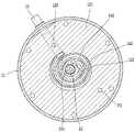
도 4는 도 2에 따른 압축부에서 1차 압축부를 보인 "II-II"선단면도,
도 5는 도 2에 따른 압축부에서 2차 압축부를 보인 "III-III"선단면도,
도 6은 도 2에 따른 압축부에서 2차 고정스크롤을 보인 "IV-IV"선단면도,
도 7은 도 2에 따른 압축부에서 중간 플레이트의 저면을 보인 "V-V"선단면도,
도 8은 도 2에 따른 압축부에서 중간 플레이트의 상면을 보인 "VI-VI"선단면도,
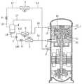
도 9는 본 실시예에 따른 2단 스크롤 압축기를 갖는 냉동사이클 장치를 냉장고에 적용한 예를 보인 계통도,
도 10은 본 발명에 의한 2단 스크롤 압축기의 다른 예를 보인 종단면도.1 is a longitudinal sectional view showing an example of a two-stage scroll compressor according to the present invention;
2 is an enlarged longitudinal sectional view of the compression unit in the compressor according to FIG. 1;
3 is a cross-sectional view showing a first fixed scroll in the compression unit according to FIG.
4 is a sectional view "II-II" showing the primary compression unit in the compression unit according to FIG.
5 is a cross-sectional view of the "III-III" showing the secondary compression unit in the compression unit according to FIG.
Figure 6 is a "IV-IV" sectional view showing a secondary fixed scroll in the compression unit according to Figure 2,
7 is a "VV" sectional view showing the bottom of the intermediate plate in the compression unit according to FIG.
8 is a "VI-VI" sectional view showing the upper surface of the intermediate plate in the compression unit according to FIG.
9 is a system diagram showing an example in which a refrigeration cycle apparatus having a two-stage scroll compressor according to the present embodiment is applied to a refrigerator;
10 is a longitudinal sectional view showing another example of a two-stage scroll compressor according to the present invention.
이하, 본 발명에 의한 2단 스크롤 압축기 및 이를 적용한 냉동사이클 장치를 첨부된 일실시예에 의거하여 상세하게 설명한다.Hereinafter, a two-stage scroll compressor according to the present invention and a refrigeration cycle apparatus using the same will be described in detail with reference to the attached embodiment.
도 1은 본 발명에 의한 2단 스크롤 압축기의 일례를 보인 종단면도이고, 도 2는 도 1에 따른 압축기에서 압축부를 확대하여 보인 종단면도이며, 도 3 내지 도 8은 도 2에 따른 "I-I", "II-II","III-III"'"IV-IV","V-V","VI-VI" 선단면도들이다.1 is a longitudinal sectional view showing an example of a two-stage scroll compressor according to the present invention, Figure 2 is a longitudinal sectional view showing an enlarged compression unit in the compressor according to Figure 1, Figures 3 to 8 is "II" according to Figure 2 , "II-II", "III-III" '"IV-IV", "VV", "VI-VI" sectional views.
이에 도시된 바와 같이, 본 실시예에 의한 2단 스크롤 압축기는, 밀폐용기(10)의 내부에는 구동모터(20)가 설치되고, 구동모터(20)의 상측에는 후술할 크랭크축(23)의 상단을 지지하는 동시에 냉매를 2단 압축하는 1차 압축부(C1)와 2차 압축부(C2)가 설치되며, 구동모터(20)의 하측에는 크랭크축(23)의 하단을 지지하는 하부프레임(30)이 설치될 수 있다.As shown in this, in the two-stage scroll compressor according to the present embodiment, the drive motor 20 is installed inside the sealed
밀폐용기(10)는 원통형으로 된 케이싱(11)의 상단과 하단을 각각 상부쉘(12)과 하부쉘(13)로 밀봉하여 형성될 수 있다. 하지만, 본 실시예와 같이 스크롤 방식으로 된 복수 개의 압축부를 구비하는 경우에는 케이싱과 상부쉘 그리고 하부쉘을 서로 체결하여 형성될 수도 있다.The
밀폐용기(10)는 케이싱(11)의 내부에 고정 결합되어 1차 압축부(C1)를 이루는 1차 고정스크롤(110)이 설치되고, 1차 고정스크롤(110)의 상측에는 밀폐용기(10)에 고정 결합되어 1차 압축부(C1)와 2차 압축부(C2)를 분리하는 중간플레이트(150)가 설치되며, 중간플레이트(150)의 상측에는 밀폐용기에 고정 결합되어 2차 고정스크롤(120)이 설치될 수 있다.The sealed
그리고 1차 고정스크롤(110)에는 후술할 1차 흡입구(114)와 연통되어 냉동사이클 장치에서 냉매가 1차 압축부(C1)로 안내되도록 1차 흡입관(15)이 연결되고, 2차 고정스크롤(120)에는 후술할 2차 흡입구(124)와 연통되어 냉동사이클 장치에서 냉매가 2차 압축부(C2)로 안내되도록 2차 흡입관(16)이 연결될 수 있다. 그리고 케이싱(11)에는 2단 압축되어 밀폐용기(10)의 내부공간으로 토출되는 냉매가 냉동사이클 장치로 안내되도록 토출관(17)이 연결될 수 있다.In addition, the primary fixed scroll 110 is connected to the
여기서, 1차 고정스크롤(110)과 중간플레이트(150)에는 1차 압축부(C1)에서 1단 압축된 냉매가 2차 압축부(C2)로 안내되도록 제1 연통유로(F1)가 형성될 수 있다. 그리고 1차 고정스크롤(110)의 하면에는 1차 압축부(C1)의 토출측과 제1 연통유로(F1)가 연통되도록 중간챔버(S3)가 형성될 수 있다.Here, the first fixed flow path (F1) is formed in the first fixed scroll 110 and the
그리고 2차 고정스크롤(120)과 중간플레이트(150) 그리고 1차 고정스크롤(110)에는 2차 압축부(C2)에서 2단 압축되어 밀페용기(10)의 상부공간(S1)으로 토출되는 냉매가 밀폐용기(10)의 하부공간(S2)으로 안내되도록 제2 연통유로(F2)가 형성될 수 있다.In addition, the second
구동모터(20)는 케이싱(11)의 내면에 고정되는 고정자(21)와, 고정자(21)의 내부에 위치하며 고정자(21)와의 상호작용에 의해 회전되는 회전자(22)를 포함할 수 있다. 회전자(22)의 중심에는 그 회전자(22)와 함께 회전하는 크랭크축(23)이 결합될 수 있다.The drive motor 20 may include a
크랭크축(23)의 중심부에는 오일유로(23a)가 크랭크축(23)의 길이방향을 따라서 관통 형성되고, 크랭크축(23)의 하단에는 하부캡(13)에 저장되어 있는 오일을 상부로 공급하기 위한 오일펌프(24)가 설치될 수 있다. 크랭크축(23)의 상단부에는 제1 편심부(23b)와 제2 편심부(23c)가 180°의 위상차를 두고 편심지게 형성될 수 있다.An
1차 압축부(C1)는 1차 고정스크롤(110)의 상면과 중간플레이트(150)의 하면 사이에 1차 선회스크롤(130)이 설치되어 이루어질 수 있다. 1차 선회스크롤(130)은 크랭크축(23)의 제1 편심부(23b)에 편심지게 결합되어 1차 고정스크롤(110)의 상면에 선회 가능하게 지지될 수 있다.The primary compression unit C1 may be formed by installing a primary pivot scroll 130 between an upper surface of the primary fixed scroll 110 and a lower surface of the
도 3 및 도 4에서와 같이, 1차 고정스크롤(110)의 경판부(111) 상면에는 고정랩(112)이 형성되고, 1차 선회스크롤(130)의 경판부(131) 하면에는 고정랩(112)과 맞물려 연속으로 이동하는 2개 한 쌍의 1차 압축실(P1)을 이루는 선회랩(132)이 형성될 수 있다.3 and 4, the
1차 고정스크롤(110)의 경판부(111) 중앙에는 크랭크축(23)이 관통되도록 축수구멍(113)이 형성되고, 1차 고정스크롤(110)의 경판부(111)의 외주면에서 1차 압축부(C1)의 최외곽 압축실로 연통되도록 반경방향으로 관통되어 1차 흡입관(15)에 연결되는 1차 흡입구(114)가 형성되며, 1차 고정스크롤(110)의 축수구멍(113) 주변에는 1차 압축부(C1)의 최종 압축실에서 중간챔버(S3)로 연통되도록 1차 토출구(115)가 형성될 수 있다.The
그리고 1차 고정스크롤(110)의 하면에는 반경방향으로 일정 간격만큼 이격되어 그 사이에 중간챔버(S3)가 형성될 수 있도록 소정의 높이만큼 돌출되는 복수 개의 챔버돌부(116a)(116b)가 형성되고, 챔버돌부(116a)(116b)에는 챔버 플레이트(117)가 밀봉 결합될 수 있다. 그리고 1차 고정스크롤(110)에는 중간챔버(S3)와 연통되는 동시에 후술할 중간플레이트(150)의 제2 연통구멍(158)에 연통되어 그 중간챔버(S3)로 토출되는 1단 압축된 냉매를 2차 압축부(C2)로 안내하도록 제1 연통구멍(118)이 형성될 수 있다.In addition, a plurality of
1차 선회스크롤(130)의 경판부(131) 중앙에는 크랭크축(23)의 제1 편심부(23b)가 결합될 수 있도록 제1 축 결합부(133)가 관통되어 형성될 수 있다. 그리고 1차 선회스크롤(130)의 경판부(131) 상면 테두리에는 후술할 제1 올담링(160)과 결합될 수 있도록 선회측 제1 키홈(134)이 형성될 수 있다.The first
그리고 1차 선회스크롤(130)의 경판부(131)에는 1차 압축실(C1)의 중간 압축실에서 후술할 중간플레이트(150) 사이의 배압실로 1차 압축되는 냉매의 일부를 바이패스시키는 제1 배압구멍(135)이 형성될 수 있다. 이에 따라 1차 선회스크롤(130)은 중간플레이트(150)와의 사이에 형성되는 배압실의 압력에 의해 축방향으로 지지되어 1차 고정스크롤(110)과 1차 선회스크롤(130) 사이의 축방향 누설이 효과적으로 방지될 수 있다.In addition, the
2차 압축부(C2)는 2차 고정스크롤(120)의 하면과 중간플레이트(150)의 상면 사이에 2차 선회스크롤(140)이 설치되어 이루어질 수 있다. 2차 선회스크롤(140)은 크랭크축(23)의 제2 편심부(23c)에 편심지게 결합되어 중간플레이트(150)의 상면에 선회 가능하게 지지될 수 있다.The secondary compression unit C2 may be formed by installing the
도 5 및 도 6에서와 같이, 2차 고정스크롤(120)의 경판부(121) 하면에는 고정랩(122)이 형성되고, 2차 선회스크롤(140)의 경판부(141) 상면에는 고정랩(122)과 맞물려 연속으로 이동하는 2개 한 쌍의 2차 압축실(P2)을 이루는 선회랩(142)이 형성될 수 있다.5 and 6, the fixing
2차 고정스크롤(120)의 경판부(121) 중앙에는 크랭크축(23)의 상단부가 관통되도록 축구멍(123)이 형성되고, 축구멍(123)의 상단에는 크랭크축(23)의 상단부를 반경방향으로 지지할 수 있도록 제1 볼베어링(41)이 설치될 수 있다. 그리고 2차 고정스크롤(120)의 경판부(121) 외주면에는 최외곽 압축실과 연통되도록 2차 흡입관이 연결되는 2차 흡입구(124)가 형성되고, 2차 고정스크롤(120)의 축구멍(123) 주변에는 2차 압축부(C2)의 최종 압축실에서 밀폐용기(110)의 상부공간(S1)으로 연통되도록 2차 토출구(125)가 형성될 수 있다. 2차 고정스크롤(120)에는 후술할 중간플레이트(150)의 제2 연통구멍(158)과 연통되는 제3 연통구멍(126)이 형성되고, 제3 연통구멍(126)은 2차 흡입구(124)에 연결될 수 있다.A
2차 선회스크롤(140)의 경판부(141) 중앙에는 크랭크축(23)의 제2 편심부(23c)가 결합될 수 있도록 제2 축 결합부(143)가 관통되어 형성될 수 있다. 그리고 2차 선회스크롤(140)의 경판부(140) 상면 테두리에는 제2 올담링(170)과 결합될 수 있도록 선회측 제2 키홈(144)이 형성될 수 있다.The second
그리고 2차 선회스크롤(140)의 경판부(141)에는 2차 압축실(C2)의 중간 압축실에서 후술할 중간플레이트(150) 사이의 배압실로 2차 압축되는 냉매의 일부를 바이패스시키는 제2 배압구멍(145)이 형성될 수 있다. 이에 따라 2차 선회스크롤(140)은 중간플레이트(150)와의 사이에 형성되는 배압실의 압력에 의해 축방향으로 지지되어 2차 고정스크롤(120)과 2차 선회스크롤(140) 사이의 축방향 누설이 효과적으로 방지될 수 있다.In addition, the hard plate part 141 of the
도 7 및 도 8에서와 같이, 중간플레이트(150)의 테두리부에는 저면은 1차 고정스크롤(110)의 경판부(111)에, 상면은 2차 고정스크롤(120)의 경판부(121)에 각각 밀봉 체결되도록 밀봉부(151)가 돌출 형성되고, 중간플레이트(150)의 중앙부에는 저면은 1차 선회스크롤(130)을, 상면은 2차 선회스크롤(140)을 각각 지지하도록 지지부(152)가 밀봉부(151)의 내주면에서 연장되어 원판 모양으로 형성될 수 있다.As shown in Figure 7 and 8, the bottom of the
지지부(152)의 중앙에는 크랭크축(23)이 관통하도록 관통구멍(153)이 형성되고, 관통구멍(153)의 하면 주변에는 1차 선회스크롤(120)이 삽입되는 제1 스크롤 안착홈(154)이 형성되며, 제1 스크롤 안착홈(154)의 주면에는 제1 올담링(160)이 결합될 수 있도록 고정측 제1 키홈(155)이 형성될 수 있다. 그리고 관통구멍(153)의 상면 주변에는 2차 선회스크롤(140)이 삽입되는 제2 스크롤 안착홈(156)이 형성되고, 제2 스크롤 안착홈(156)의 주면에는 제2 올담링(170)이 결합될 수 있도록 고정측 제2 키홈(158)이 형성될 수 있다. 지지부(152)의 가장자리 또는 밀봉부(151)에는 1차 고정스크롤(120)의 제1 연통구멍(118)과 연결되어 1단 압축된 냉매를 2차 압축부(C2)로 안내하기 위한 제2 연통구멍(158)이 관통 형성될 수 있다.A through
그리고 관통구멍(153)의 내주면에서 밀봉부(151)의 외주면으로는 크랭크축(23)을 통해 공급되는 오일의 일부를 배출시킬 수 있도록 배유구멍(159)이 반경방향으로 형성되고, 밀봉부(151)의 외주면에는 배유구멍(158)이 밀폐용기(10)의 내부공간에 연통될 수 있도록 배유홈(159a)이 단차지게 형성될 수 있다.In addition, a
하부프레임(30)의 중앙에는 크랭크축(23)의 하단부가 관통하도록 축구멍(31)이 형성되고, 하부프레임(30)의 축구멍(31)에는 크랭크축(23)의 하단부를 반경방향으로 지지하도록 제2 볼베어링(42)이 설치될 수 있다.A shaft hole 31 is formed in the center of the
한편, 1차 압축부(C1)와 2차 압축부(C2)의 각 고정랩(112)(122)과 선회랩(132)(142)은 인볼류트 곡선으로 형성될 수도 있지만, 경우에 따라서는 인벌류트 곡선이 아닌 다른 곡선을 갖도록 형성할 수도 있다. 1차 압축부의 고정랩 및 선회랩은 2차 압축부의 고정랩 및 선회랩과 동일한 형상으로 형성될 수 있다.Meanwhile, each of the fixed wraps 112 and 122 and the turning wraps 132 and 142 of the primary compression unit C1 and the secondary compression unit C2 may be formed in an involute curve. It may be formed to have a curve other than the involute curve. The fixed wrap and the swing wrap of the primary compression section may be formed in the same shape as the fixed wrap and the swing wrap of the secondary compression section.
도 4는 1차 압축부를 이루는 고정랩과 선회랩의 결합상태를 보인 평면도이다. 이를 참조하면, 제1 축 결합부(133)의 중심을 O라 하고, 두 개의 접촉점을 각각 A, B라 할 때, 두 개의 접촉점(A, B)과 축 결합부의 중심(O)을 연결한 두 개의 직선에 의해 정의되는 각α는 360°보다 작고, 각각의 접촉점에서의 법선 벡터 사이의 거리 ℓ도 0보다 큰 값을 갖는 것을 알 수 있다. 이에 따라, 토출 직전의 외측 압축실이 인볼류트 곡선으로 이루어진 고정랩과 선회랩을 갖는 경우에 비해 더 작은 볼륨을 갖게 되므로 압축비가 증가될 수 있다.Figure 4 is a plan view showing a coupling state of the fixed wrap and the rotating wrap forming the primary compression. Referring to this, when the center of the first
그리고, 고정랩(112)의 내측 단부 부근에 제1 축 결합부(133)측으로 돌출되는 돌기부(112a)가 형성되고, 돌기부(112a)에는 그 돌기부(112a)로부터 돌출되도록 형성되는 접촉부(112b)가 더 형성될 수 있다. 이에 따라, 고정랩의 내측 단부는 다른 부분에 비해서 보다 큰 두께를 갖도록 형성될 수 있다.The
제1 축 결합부(133)에는 돌기부(112a)와 맞물리게 되는 오목부(132a)가 형성될 수 있다. 오목부(132a)의 일측벽은 돌기부(112a)의 접촉부(112b)와 접촉하면서 외측 압축실의 일측 접촉점(A)을 형성하게 될 수 있다.The first
한편, 2차 압축부(C2)의 고정랩(122) 및 선회랩(142)은 전술한 1차 압축부(C1)의 고정랩(112) 및 선회랩(132)과 동일한 형상으로 형성될 수 있으므로 이에 대한 설명은 생략한다.Meanwhile, the fixed
도면중 미설명 부호인Unexplained sign in the drawing
상기와 같은 본 실시예에 의한 2단 스크롤 압축기는, 구동모터(20)에 전원을 인가하여 크랭크축(23)이 회전을 하면, 크랭크축(23)에 의해 제1 압축부(C1)의 1차 선회스크롤(130)이 1차 고정스크롤(110)에 대해 선회운동을 하면서 2개 한 쌍의 1차 압축실(P1)을 형성하게 된다. 그러면, 1차 흡입구(114)를 통해 냉매가 1차 압축실(P1)로 흡입되어 안쪽으로 이동을 하면서 1차 압축되고, 이 1차 압축실(P1)에서 1단 압축되는 냉매는 1차 고정스크롤(110)의 1차 토출구(115)를 통해 중간챔버(S3)로 토출된다. 이때, 중간챔버(S3)의 체적이 1차 압축부(C1)의 최종 압축실 체적보다 커서 중간챔버(S3)로 토출되는 1단 압축된 냉매는 중간압을 형성하게 된다.In the two-stage scroll compressor according to the present embodiment as described above, when the
한편, 1차 선회스크롤(130)과 함께 2차 선회스크롤(140)이 2차 고정스크롤(120)에 대해 선회운동을 하면서 2개 한 쌍의 2차 압축실(P2)을 형성하게 된다. 그러면, 중간챔버(S3)로 토출된 1단 압축된 냉매는 유로를 따라 제2 압축부(C2)의 2차 압축실(P2)로 흡입되고, 이 2차 압축실(P2)로 흡입되는 냉매는 2차 선회스크롤(140)의 선회운동시 안쪽으로 이동하여 2단 압축을 하고, 제2 압축부(C2)에서 2단 압축된 냉매는 밀폐용기(10)의 내부공간으로 토출되었다가 냉동사이클로 배출되는 일련의 과정을 반복하게 된다.On the other hand, the
상기와 같은 본 실시예에 의한 2단 스크롤 압축기는 한 개의 밀폐용기 안에 스크롤 방식의 1차 압축부와 2차 압축부가 함께 구비됨에 따라 높은 압축 효율을 얻을 수 있고 압축 소음을 크게 줄일 수 있다.The two-stage scroll compressor according to the present embodiment as described above is provided with a scroll type primary compression unit and a secondary compression unit in one hermetically sealed container, thereby obtaining high compression efficiency and greatly reducing compression noise.
그러면서도 1차 압축부와 2차 압축부가 한 개의 밀폐용기 안에 구비됨에 따라 냉매와 함께 토출되는 오일이 동일한 밀폐용기로 회수되어 각 압축부 간 오일불평형을 미연에 방지할 수 있고 이를 통해 냉동 능력을 높이고 마모를 방지하여 압축기를 포함한 냉동사이클 장치의 신뢰성을 향상시킬 수 있다.At the same time, since the primary compression unit and the secondary compression unit are provided in one sealed container, the oil discharged together with the refrigerant is recovered in the same sealed container, thereby preventing oil unbalance between the compression units in advance, thereby increasing the freezing capacity. By preventing wear, it is possible to improve the reliability of the refrigeration cycle apparatus including the compressor.
도 9는 본 실시예에 따른 2단 스크롤 압축기를 갖는 냉동사이클 장치를 냉장고에 적용한 예를 보인 계통도이다. 이에 도시된 바와 같이, 본 실시예에 의한 냉동사이클 장치는 2단 스크롤 압축기(이하, 2단 압축기)(1)의 토출관(17)에 제1 냉매관(L1)이 연결되고, 제1 냉매관(L1)의 중간에는 응축기(2)가 연결되며, 응축기(2)의 출구에는 제2 냉매관(L2)이 연결되고, 제2 냉매관(L2)에는 팽창기(3)가 연결되며, 팽창기(3)의 출구에는 제3 냉매관(L3)이 연결되고, 제3 냉매관(L3)에는 냉매저장부(reservoir)(4)가 연결될 수 있다.9 is a system diagram showing an example in which a refrigeration cycle apparatus having a two-stage scroll compressor according to the present embodiment is applied to a refrigerator. As shown in the drawing, in the refrigeration cycle apparatus according to the present embodiment, the first refrigerant pipe L1 is connected to the
그리고 냉매저장부(4)의 출구에는 제4 냉매관(L4)이 연결되고, 제4 냉매관(L4)에는 냉매의 유동방향을 제어하도록 3방 밸브로 된 냉매전환밸브(5)가 연결되고, 냉매전환밸브(5)의 제1 출구에는 제1 분지관(L41)이, 제2 출구에는 팽창기(6)를 갖는 제2 분지관(L42)이 각각 연결될 수 있다.A fourth refrigerant pipe (L4) is connected to the outlet of the refrigerant storage unit (4), and a refrigerant switching valve (5) consisting of a three-way valve is connected to the fourth refrigerant pipe (L4) to control the flow direction of the refrigerant. The first branch pipe L41 may be connected to the first outlet of the
그리고 제1 분지관(L41)에는 냉동실측 증발기(7)가, 제2 분지관(L42)에는 냉장실측 증발기(8)가 각각 연결되고, 냉동실측 증발기(7)의 출구에는 제5 냉매관(L5)이, 냉장실측 증발기(8)의 출구에는 제6 냉매관(L6)이 각각 연결되며, 제5 냉매관(L5)은 1차 흡입관(15)에, 제6 냉매관(L6)은 2차 흡입관(16)에 각각 연결될 수 있다.A freezer
그리고 냉매저장부(4)의 타단에는 바이패스관(L7)이 연결되고, 바이패스관(L7)은 냉동실측 증발기(8)와 2차 흡입관(16) 사이의 제6 냉매관(L6)에 연결될 수 있다.The other end of the
상기와 같은 본 실시예에 의한 냉동사이클 장치는, 냉장고의 운전모드에 따라 냉매전환밸브를 냉매의 유동방향을 냉동실측 증발기 또는 냉장실측 증발기 방향으로 선택적으로 제어함으로써 냉장고의 냉동실과 냉장실을 모두 운전하는 동시운전 또는 냉동실만 운전하는 냉동실 운전 또는 냉장실만 운전하는 냉장실 운전으로 진행될 수 있다.In the refrigeration cycle apparatus according to the present embodiment as described above, the refrigerant switching valve according to the operation mode of the refrigerator selectively controls the flow direction of the refrigerant toward the freezer compartment side evaporator or the refrigerator compartment side evaporator to operate both the freezer compartment and the refrigerator compartment of the refrigerator. Simultaneous operation or freezer operation, which operates only the freezer compartment, or the refrigerating compartment operation, which operates only the refrigerating compartment, may be performed.
예를 들어, 냉동실과 냉장실을 모두 운전시키는 동시운전모드인 경우에는, 냉매전환밸브(5)의 제1 출구와 제2 출구가 모두 열리면서 응축기(2)와 팽창기(3)를 통과하는 냉매가 냉동실측 증발기(7)와 냉장실측 증발기(8) 방향으로 이동하게 된다.For example, in the simultaneous operation mode in which both the freezing compartment and the refrigerating compartment are operated, the refrigerant passing through the
그러면, 냉동실측 증발기(7)를 거쳐 1차 압축부(C1)로 흡입되는 냉매는 그 1차 압축부(C1)에서 1단 압축되어 토출되고, 1차 압축부(C1)에서 중간챔버(S3)로 토출되는 1단 압축된 중간압의 냉매는 2차 압축부(C2)로 흡입된다. 이때, 냉장실측 증발기(8)를 통과하는 냉매가 제6 냉매관(L6)과 2차 흡입관(16)을 통해 2차 압축부(C2)로 흡입되면서 1단 압축된 냉매와 합쳐져 2차 압축부(C2)로 흡입된다.Then, the refrigerant sucked into the primary compression unit C1 via the freezer
그러면, 1단 압축된 냉매와 냉장실측 증발기(8)를 통과한 냉매가 2차 압축부(C2)에서 압축되어 압축기(1)의 밀폐용기 내부공간으로 토출되고, 2차 압축부(C2)에서 밀폐용기의 내부공간으로 토출되는 냉매는 토출관(17)과 제1 냉매관(L1)을 통해 응축기(2)로 이동하여 응축되며, 응축기(2)에서 응축된 냉매는 제2 냉매관(L2)과 팽창기(3) 그리고 제3 냉매관(L3)을 통과한 후 냉매전환밸브(5)에서 냉동실측 증발기(7)와 냉장실측 증발기(8) 방향으로 분배되면서 순환되는 일련의 과정을 반복하게 된다.Then, the refrigerant compressed through the first stage and the refrigerant passing through the refrigerating
한편, 냉동실 운전모드인 경우에는, 냉매전환밸브(5)가 냉장실측 증발기(7), 즉 제2 출구는 차단하고 냉동실측 증발기(8) 쪽인 제1 출구만 개방하여 응축기(2)를 통과하는 냉매가 냉동실측 증발기(7) 방향으로만 이동할 수 있도록 한다. 여기서, 1차 압축부(C1)와 2차 압축부(C2)는 1차 압축부(C1)로 흡입되는 냉매를 연속하여 2단으로 압축하면서 순환되도록 하는 일련의 과정을 반복함으로써 냉동사이클의 냉매가 냉동실 운전에 적합한 압력으로 신속하게 압축되도록 한다.On the other hand, in the freezer compartment operation mode, the
한편, 냉장실 운전모드인 경우에는, 냉매전환밸브(5)가 제1 출구는 차단하고 제2 출구는 개방한다. 그리고 1차 압축부(C1)는 정지시키고 2차 압축부(C2)만 운전을 개시한다. 그러면, 응축기(2)를 통과하는 냉매는 냉장실측 증발기(8) 방향으로만 이동하여 2차 흡입구(124)를 통해 2차 압축부(C2)에서 1단 압축되어 응축기(2)로 이동하는 일련의 과정을 반복함으로써 냉동사이클 장치의 냉매가 과압축되지 않고 냉장실 운전에 적합한 압력으로 압축되도록 한다.On the other hand, in the refrigerating chamber operation mode, the
상기와 같은 냉동사이클 장치의 운전 과정에서, 오일은 냉매와 함께 이동을 하면서 1차 압축부(C1)와 2차 압축부(C2)를 순환하게 되지만, 1차 압축부(C1)와 2차 압축부(C2)가 한 개의 밀폐용기(10) 내에 설치되고 한 개의 크랭크축(23)에 의해 오일을 공급받게 됨에 따라 냉장고의 운전모드에 따른 1차 압축부(C1)와 2차 압축부(C2) 사이에서의 오일 불균형을 미연에 방지할 수 있다.In the operation process of the refrigeration cycle device as described above, the oil is circulated with the primary compression unit (C1) and the secondary compression unit (C2) while moving with the refrigerant, but the primary compression unit (C1) and secondary compression As the unit C2 is installed in one
한편, 본 발명에 의한 2단 스크롤 압축기에 대한 다른 실시예가 있는 경우는 다음과 같다.On the other hand, if there is another embodiment of a two-stage scroll compressor according to the present invention.
즉, 전술한 실시예에서는 1차 고정스크롤과 2차 고정스크롤 사이에 중간플레이트가 고정 설치되고, 1차 고정스크롤과 중간플레이트의 사이에는 1차 선회스크롤이, 2차 고정스크롤과 중간플레이트의 사이에는 2차 선회스크롤이 각각 구비되는 것이나, 본 실시예는 도 10에서와 같이 1차 고정스크롤과 2차 고정스크롤이 일체로 된 일체형 고정스크롤(210)이 형성되어 1차 선회스크롤(220)과 2차 선회스크롤(230) 사이에 배치되도록 하는 것이다. 도면중 미설명 부호인 15는 1차 흡입관, 16은 2차 흡입관, 17은 토출관, 20은 구동모터, 21은 고정자, 22는 회전자, 23은 크랭크축, 231은 2차 토출구, 240은 제1 프레임, 250은 제2 프레임, 251은 토출구멍이다.That is, in the above-described embodiment, the intermediate plate is fixedly installed between the primary fixed scroll and the secondary fixed scroll, and the primary swing scroll is disposed between the primary fixed scroll and the intermediate plate, and between the secondary fixed scroll and the intermediate plate. The secondary turning scroll is provided in each of the present embodiment, but as shown in FIG. 10, the first fixed scroll and an integral fixed
이 경우에도 기본적인 구성과 작용 효과는 전술한 실시예의 2단 스크롤 압축기 및 이를 적용하는 냉동사이클 장치와 유사하다. 다만, 본 실시예의 경우에는 1차 고정스크롤과 2차 고정스크롤이 일체된 한 개의 고정스크롤(210)을 형성하면서 전술한 실시예의 중간플레이트 역할을 함에 따라 별도의 중간플레이트가 필요 없게 될 수 있다.Even in this case, the basic configuration and operation effects are similar to those of the two-stage scroll compressor and the refrigeration cycle apparatus employing the same. However, in the present exemplary embodiment, since the first fixed scroll and the second fixed scroll form one fixed
뿐만 아니라, 일체형 고정스크롤(210)에 1차 압축실(P1)의 토출구(211)와 2차 압축실(P2)의 흡입구(212)를 연통시킴에 따라 별도의 중간챔버가 필요 없게 될 수 있다.In addition, since the
따라서, 전술한 실시예에서의 중간플레이트와 중간챔버가 제거됨에 따라 그만큼 재료비용과 조립비용이 절감될 뿐만 아니라, 중간플레이트와 중간챔버가 차지하는 공간을 줄여 압축기의 소형화를 이룰 수 있다.Therefore, as the intermediate plate and the intermediate chamber are removed in the above-described embodiment, not only the material cost and the assembly cost can be reduced, but also the compactness of the compressor can be achieved by reducing the space occupied by the intermediate plate and the intermediate chamber.
23 : 크랭크축23b,23c : 제1,제2 편심부
41,42 : 베어링110 : 1차 고정스크롤
112 : 1차 고정랩114 : 1차 흡입구
115 : 1차 토출구116a,116b : 챔버돌부
120 : 2차 고정스크롤122 : 2차 고정랩
124 : 2차 흡입구125 : 2차 토출구
130 : 1차 선회스크롤132 : 1차 선회랩
133 : 축 결합부135 : 배압구멍
140 : 2차 선회스크롤142 : 2차 선회랩
143 : 축 결합부145 : 배압구멍
150 : 중간플레이트F1 : 제1 연통구멍
F2 : 제2 연통유로23:
41,42: bearing 110: primary fixed scroll
112: primary fixed wrap 114: primary inlet
115:
120: secondary fixed scroll 122: secondary fixed wrap
124: secondary inlet 125: secondary outlet
130: 1st turn scroll 132: 1st turn wrap
133: shaft coupling portion 135: back pressure hole
140: 2nd turning scroll 142: 2nd turning wrap
143: shaft coupling portion 145: back pressure hole
150: intermediate plate F1: first communication hole
F2: second communication channel
Claims (14)
Translated fromKorean상기 밀폐용기의 내부에 고정 결합되는 구동모터;
상기 구동모터의 회전자에 결합되는 크랭크축;
상기 밀폐용기에 고정 결합되고 고정랩이 형성되는 1차 고정스크롤;
상기 크랭크축에 편심지게 결합되고 상기 1차 고정스크롤의 고정랩에 맞물려 선회운동을 하면서 1차 압축실을 형성하도록 선회랩이 구비되는 1차 선회스크롤;
상기 밀폐용기에 고정 결합되고 고정랩이 형성되는 2차 고정스크롤; 및
상기 크랭크축에 편심지게 결합되고 상기 2차 고정스크롤의 고정랩에 맞물려 선회운동을 하면서 2차 압축실을 형성하도록 선회랩이 구비되는 2차 선회스크롤;을 포함하고,
상기 1차 선회스크롤과 2차 선회스크롤의 사이에는 상기 1차 선회스크롤과 2차 선회스크롤의 배면을 각각 지지하는 중간플레이트가 설치되며,
상기 중간플레이트에는 상기 크랭크축이 관통되는 관통구멍이 형성되고, 상기 관통구멍에서 외주면으로 관통되어 상기 밀폐용기의 내부공간에 연통되는 배유구멍이 형성되는 2단 스크롤 압축기.Airtight containers;
A drive motor fixedly coupled to the inside of the sealed container;
A crank shaft coupled to the rotor of the drive motor;
A first fixed scroll fixed to the sealed container and having a fixed wrap formed thereon;
A primary pivoting scroll eccentrically coupled to the crankshaft and provided with a pivoting wrap to form a primary compression chamber while pivoting in engagement with the stationary wrap of the primary fixed scroll;
A second fixed scroll fixed to the sealed container and having a fixed wrap formed thereon; And
And a secondary turning scroll which is eccentrically coupled to the crankshaft and provided with a turning wrap to form a secondary compression chamber while pivoting in engagement with the fixed wrap of the secondary fixed scroll.
An intermediate plate is provided between the primary turning scroll and the secondary turning scroll to support the back of the primary turning scroll and the secondary turning scroll, respectively.
And a through hole through which the crankshaft penetrates the intermediate plate, and a drainage hole penetrating from the through hole to the outer circumferential surface to communicate with the inner space of the sealed container.
상기 1차 압축실의 토출측과 상기 2차 압축실의 흡입측은 서로 연통되도록 형성되는 2단 스크롤 압축기.The method of claim 1,
And a discharge side of the primary compression chamber and a suction side of the secondary compression chamber are configured to communicate with each other.
상기 1차 압축실의 흡입측과 상기 2차 압축실의 흡입측은 냉동사이클 장치의 증발기에 각각 연통되도록 상기 밀폐용기를 관통하여 결합되는 각각의 흡입관에 각각 연통되고,
상기 2차 압축실은 상기 밀폐용기의 내부공간에 연통되는 2단 스크롤 압축기.The method of claim 2,
The suction side of the primary compression chamber and the suction side of the secondary compression chamber are respectively communicated with respective suction pipes coupled through the sealed container so as to communicate with the evaporator of the refrigerating cycle apparatus, respectively.
The second compression chamber is a two-stage scroll compressor in communication with the inner space of the sealed container.
상기 1차 고정스크롤과 2차 고정스크롤은 일체로 형성되어 상기 1차 선회스크롤과 2차 선회스크롤 사이에서 상기 밀폐용기에 고정 설치되는 2단 스크롤 압축기.The method of claim 1,
And the first fixed scroll and the second fixed scroll are integrally formed to be fixedly installed in the airtight container between the primary swing scroll and the secondary swing scroll.
상기 1차 선회스크롤에는 상기 1차 압축실에서 상기 1차 선회스크롤의 배면과 중간플레이트의 일측면의 사이로 냉매를 배기시키는 제1 배압구멍이 형성되며,
상기 2차 선회스크롤에는 상기 2차 압축실에서 상기 2차 선회스크롤의 배면과 중간플레이트의 타측면 사이로 냉매를 배기시키는 제2 배압구멍이 형성되는 2단 스크롤 압축기.The method of claim 1,
The first turning scroll is formed with a first back pressure hole for exhausting the refrigerant between the back surface of the first turning scroll and one side of the intermediate plate in the first compression chamber,
And a second back pressure hole formed in the secondary swing scroll to exhaust the refrigerant between the rear surface of the secondary swing scroll and the other side of the intermediate plate in the secondary compression chamber.
상기 크랭크축의 일단에는 상기 1차 선회스크롤과 2차 선회스크롤에 각각 결합되도록 1차 편심부와 2차 편심부가 형성되고,
상기 1차 편심부와 2차 편심부는 평면상에서 180도의 위상차를 두고 형성되는 2단 스크롤 압축기.The method of claim 1,
One end of the crankshaft is formed with a primary eccentric portion and a secondary eccentric portion to be coupled to the primary turning scroll and the secondary turning scroll, respectively,
And the first eccentric portion and the second eccentric portion are formed with a phase difference of 180 degrees on a plane.
상기 크랭크축의 일측은 상기 구동모터의 일측에서 상기 밀폐용기에 고정되는 프레임에 지지되고,
상기 크랭크축의 타측은 상기 구동모터의 타측에서 상기 1차 고정스크롤과 상기 1차 선회스크롤과 상기 중간플레이트와 상기 2차 선회스크롤을 관통하여 상기 2차 고정스크롤에 지지되는 2단 스크롤 압축기.The method of claim 1,
One side of the crankshaft is supported by a frame fixed to the hermetic container at one side of the drive motor,
And the other side of the crankshaft is supported by the secondary fixed scroll by passing through the primary fixed scroll, the primary pivot scroll, the intermediate plate, and the secondary pivot scroll on the other side of the drive motor.
상기 밀폐용기의 내부에 고정 결합되는 구동모터;
상기 구동모터의 회전자에 결합되는 크랭크축;
상기 밀폐용기에 고정 결합되고 고정랩이 형성되는 1차 고정스크롤;
상기 크랭크축에 편심지게 결합되고 상기 1차 고정스크롤의 고정랩에 맞물려 선회운동을 하면서 1차 압축실을 형성하도록 선회랩이 구비되는 1차 선회스크롤;
상기 밀폐용기에 고정 결합되고 고정랩이 형성되는 2차 고정스크롤; 및
상기 크랭크축에 편심지게 결합되고 상기 2차 고정스크롤의 고정랩에 맞물려 선회운동을 하면서 2차 압축실을 형성하도록 선회랩이 구비되는 2차 선회스크롤;을 포함하고,
상기 1차 압축실과 2차 압축실의 사이에는 상기 1차 압축실에서 토출되는 냉매를 상기 2차 압축실로 유도하는 중간챔버가 형성되며,
상기 1차 고정스크롤의 배면에는 상기 1차 압축실의 토출구가 수용되도록 챔버돌부가 형성되고,
상기 챔버돌부의 상단에는 그 챔버돌부의 안쪽에 상기 중간챔버가 형성되도록 챔버커버가 복개 결합되는 2단 스크롤 압축기.Airtight containers;
A drive motor fixedly coupled to the inside of the hermetic container;
A crank shaft coupled to the rotor of the drive motor;
A first fixed scroll fixed to the sealed container and having a fixed wrap formed thereon;
A primary pivoting scroll eccentrically coupled to the crankshaft and provided with a pivoting wrap to form a primary compression chamber while pivoting in engagement with the stationary wrap of the primary fixed scroll;
A second fixed scroll fixed to the sealed container and having a fixed wrap formed thereon; And
And a secondary turning scroll which is eccentrically coupled to the crankshaft and provided with a turning wrap to form a secondary compression chamber while pivoting in engagement with the fixed wrap of the secondary fixed scroll.
An intermediate chamber is formed between the primary compression chamber and the secondary compression chamber to guide the refrigerant discharged from the primary compression chamber to the secondary compression chamber.
A chamber protrusion is formed on the rear surface of the primary fixed scroll to accommodate the discharge port of the primary compression chamber.
And a chamber cover coupled to the upper end of the chamber protrusion so that the intermediate chamber is formed inside the chamber protrusion.
상기 1차 고정스크롤과 2차 고정스크롤은 일체로 형성되어 상기 1차 선회스크롤과 2차 선회스크롤 사이에서 상기 밀폐용기에 고정 설치되는 2단 스크롤 압축기.The method of claim 9,
And the first fixed scroll and the second fixed scroll are integrally formed to be fixedly installed in the airtight container between the primary swing scroll and the secondary swing scroll.
상기 크랭크축의 일단에는 상기 1차 선회스크롤과 2차 선회스크롤에 각각 결합되도록 1차 편심부와 2차 편심부가 형성되고,
상기 1차 편심부와 2차 편심부는 평면상에서 180도의 위상차를 두고 형성되는 2단 스크롤 압축기.The method of claim 9,
One end of the crankshaft is formed with a primary eccentric portion and a secondary eccentric portion to be coupled to the primary turning scroll and the secondary turning scroll, respectively,
And the first eccentric portion and the second eccentric portion are formed with a phase difference of 180 degrees on a plane.
상기 압축기의 토출측에 연결되는 응축기; 및
상기 응축기에 연결되고, 중간에 복수 개로 분관되어 구비되는 복수 개의 증발기;를 포함하고,
상기 압축기는,
상기 제1항 내지 제7항, 제9항 내지 제11항 중 어느 한 항의 2단 스크롤 압축기로 이루어진 2단 스크롤 압축기를 가지는 냉동사이클 장치.compressor;
A condenser connected to the discharge side of the compressor; And
And a plurality of evaporators connected to the condenser and provided with a plurality of branches in the middle.
The compressor,
12. A refrigeration cycle apparatus having a two-stage scroll compressor comprising the two-stage scroll compressor of any one of claims 1 to 7.
상기 2차 고정스크롤에는 상기 2차 압축실과 연통되도록 2차 흡입구가 형성되고,
상기 2차 흡입구는 상기 1차 압축실의 토출측과 연통되는 동시에 상기 밀폐용기를 관통하여 해당 증발기에 연통되는 2단 스크롤 압축기를 가지는 냉동사이클 장치.The method of claim 12,
A secondary suction port is formed in the secondary fixed scroll to communicate with the secondary compression chamber,
And the secondary suction port has a two-stage scroll compressor communicating with the discharge side of the primary compression chamber and through the sealed container and communicating with the evaporator.
상기 응축기와 복수 개의 증발기 사이에는 냉매저장부가 설치되고, 상기 냉매저장부는 냉매관에 의해 복수 개의 증발기와 병렬 연결되는 동시에 바이패스관에 의해 상기 2차 압축실에 연통되는 2단 스크롤 압축기를 가지는 냉동사이클 장치.
The method of claim 13,
A refrigerant storage unit is installed between the condenser and the plurality of evaporators, and the refrigerant storage unit has a two-stage scroll compressor connected in parallel with the plurality of evaporators by a refrigerant pipe and communicating with the secondary compression chamber by a bypass pipe. Cycle device.
Priority Applications (1)
| Application Number | Priority Date | Filing Date | Title |
|---|---|---|---|
| KR1020130079883AKR102051096B1 (en) | 2013-07-08 | 2013-07-08 | 2-stage scroll compressor and refrigerating cycle system having the same |
Applications Claiming Priority (1)
| Application Number | Priority Date | Filing Date | Title |
|---|---|---|---|
| KR1020130079883AKR102051096B1 (en) | 2013-07-08 | 2013-07-08 | 2-stage scroll compressor and refrigerating cycle system having the same |
Publications (2)
| Publication Number | Publication Date |
|---|---|
| KR20150006278A KR20150006278A (en) | 2015-01-16 |
| KR102051096B1true KR102051096B1 (en) | 2019-12-02 |
Family
ID=52569720
Family Applications (1)
| Application Number | Title | Priority Date | Filing Date |
|---|---|---|---|
| KR1020130079883AExpired - Fee RelatedKR102051096B1 (en) | 2013-07-08 | 2013-07-08 | 2-stage scroll compressor and refrigerating cycle system having the same |
Country Status (1)
| Country | Link |
|---|---|
| KR (1) | KR102051096B1 (en) |
Families Citing this family (11)
| Publication number | Priority date | Publication date | Assignee | Title |
|---|---|---|---|---|
| US10465954B2 (en) | 2017-02-06 | 2019-11-05 | Emerson Climate Technologies, Inc. | Co-rotating compressor with multiple compression mechanisms and system having same |
| US11111921B2 (en) | 2017-02-06 | 2021-09-07 | Emerson Climate Technologies, Inc. | Co-rotating compressor |
| US10995754B2 (en) | 2017-02-06 | 2021-05-04 | Emerson Climate Technologies, Inc. | Co-rotating compressor |
| US10215174B2 (en) | 2017-02-06 | 2019-02-26 | Emerson Climate Technologies, Inc. | Co-rotating compressor with multiple compression mechanisms |
| KR102668142B1 (en) | 2019-11-15 | 2024-05-23 | 코프랜드 엘피 | Co-rotating scroll compressor |
| US11732713B2 (en) | 2021-11-05 | 2023-08-22 | Emerson Climate Technologies, Inc. | Co-rotating scroll compressor having synchronization mechanism |
| US12104594B2 (en) | 2021-11-05 | 2024-10-01 | Copeland Lp | Co-rotating compressor |
| US11624366B1 (en) | 2021-11-05 | 2023-04-11 | Emerson Climate Technologies, Inc. | Co-rotating scroll compressor having first and second Oldham couplings |
| KR102660782B1 (en)* | 2022-04-20 | 2024-04-29 | 엘지전자 주식회사 | Scroll compressor |
| KR102639608B1 (en)* | 2022-04-20 | 2024-02-26 | 엘지전자 주식회사 | Scroll compressor |
| KR20240017262A (en)* | 2022-07-29 | 2024-02-07 | 엘지전자 주식회사 | Scroll Compressor |
Citations (3)
| Publication number | Priority date | Publication date | Assignee | Title |
|---|---|---|---|---|
| JP2003254661A (en)* | 2002-02-27 | 2003-09-10 | Toshiba Corp | refrigerator |
| JP2004169608A (en)* | 2002-11-20 | 2004-06-17 | Matsushita Electric Ind Co Ltd | Scroll type air supply device |
| JP2007023827A (en)* | 2005-07-13 | 2007-02-01 | Mitsubishi Electric Corp | Two-stage compression scroll compressor |
Family Cites Families (1)
| Publication number | Priority date | Publication date | Assignee | Title |
|---|---|---|---|---|
| KR20130031736A (en)* | 2011-09-21 | 2013-03-29 | 엘지전자 주식회사 | Scroll compressor |
- 2013
- 2013-07-08KRKR1020130079883Apatent/KR102051096B1/ennot_activeExpired - Fee Related
Patent Citations (3)
| Publication number | Priority date | Publication date | Assignee | Title |
|---|---|---|---|---|
| JP2003254661A (en)* | 2002-02-27 | 2003-09-10 | Toshiba Corp | refrigerator |
| JP2004169608A (en)* | 2002-11-20 | 2004-06-17 | Matsushita Electric Ind Co Ltd | Scroll type air supply device |
| JP2007023827A (en)* | 2005-07-13 | 2007-02-01 | Mitsubishi Electric Corp | Two-stage compression scroll compressor |
Also Published As
| Publication number | Publication date |
|---|---|
| KR20150006278A (en) | 2015-01-16 |
Similar Documents
| Publication | Publication Date | Title |
|---|---|---|
| KR102051096B1 (en) | 2-stage scroll compressor and refrigerating cycle system having the same | |
| KR101810461B1 (en) | Scroll compressor | |
| CN101939548B (en) | Compressor and freezer | |
| EP2574791B1 (en) | Scroll compressor | |
| CN100498121C (en) | Refrigerant cycle device | |
| EP2055956B1 (en) | Multistage compressor | |
| KR101681585B1 (en) | Twin type rotary compressor | |
| CN101939546B (en) | Fluid machine | |
| US20070041852A1 (en) | Rotary compressor | |
| KR100725893B1 (en) | Scroll Fluid Machine | |
| US20110142705A1 (en) | Rotary compressor | |
| US8517702B2 (en) | Rotary compressor with enhanced sealing between mode switching device and chamber thereof | |
| US11448072B2 (en) | Rotary compressor | |
| KR20190000035A (en) | Scroll compressor and air conditioner having the same | |
| KR20100054667A (en) | Hermetric compressor and refrigeration cycle device having the same | |
| KR101587174B1 (en) | Rotary compressor | |
| KR20090013041A (en) | Hermetic compressor and refrigeration cycle device using the same | |
| KR101454239B1 (en) | Scroll compressor and refrigeration cycle device using it | |
| JP2010156246A (en) | Compressor | |
| KR101194608B1 (en) | Modulation type rotary compressor | |
| KR102060470B1 (en) | 2-stage compressor | |
| JP2007146663A (en) | Hermetic compressor and refrigeration cycle apparatus | |
| KR100595581B1 (en) | Variable capacity device of vane compressor | |
| JP2008144670A (en) | Rotary compressor | |
| KR20000005606A (en) | Rotary compressor having a plurality of compression chambers for multistage compression |
Legal Events
| Date | Code | Title | Description |
|---|---|---|---|
| PA0109 | Patent application | St.27 status event code:A-0-1-A10-A12-nap-PA0109 | |
| PG1501 | Laying open of application | St.27 status event code:A-1-1-Q10-Q12-nap-PG1501 | |
| PN2301 | Change of applicant | St.27 status event code:A-3-3-R10-R13-asn-PN2301 St.27 status event code:A-3-3-R10-R11-asn-PN2301 | |
| P22-X000 | Classification modified | St.27 status event code:A-2-2-P10-P22-nap-X000 | |
| A201 | Request for examination | ||
| PA0201 | Request for examination | St.27 status event code:A-1-2-D10-D11-exm-PA0201 | |
| D13-X000 | Search requested | St.27 status event code:A-1-2-D10-D13-srh-X000 | |
| D14-X000 | Search report completed | St.27 status event code:A-1-2-D10-D14-srh-X000 | |
| E902 | Notification of reason for refusal | ||
| PE0902 | Notice of grounds for rejection | St.27 status event code:A-1-2-D10-D21-exm-PE0902 | |
| E13-X000 | Pre-grant limitation requested | St.27 status event code:A-2-3-E10-E13-lim-X000 | |
| P11-X000 | Amendment of application requested | St.27 status event code:A-2-2-P10-P11-nap-X000 | |
| P13-X000 | Application amended | St.27 status event code:A-2-2-P10-P13-nap-X000 | |
| E701 | Decision to grant or registration of patent right | ||
| PE0701 | Decision of registration | St.27 status event code:A-1-2-D10-D22-exm-PE0701 | |
| GRNT | Written decision to grant | ||
| PR0701 | Registration of establishment | St.27 status event code:A-2-4-F10-F11-exm-PR0701 | |
| PR1002 | Payment of registration fee | St.27 status event code:A-2-2-U10-U11-oth-PR1002 Fee payment year number:1 | |
| PG1601 | Publication of registration | St.27 status event code:A-4-4-Q10-Q13-nap-PG1601 | |
| PN2301 | Change of applicant | St.27 status event code:A-5-5-R10-R13-asn-PN2301 St.27 status event code:A-5-5-R10-R11-asn-PN2301 | |
| PR1001 | Payment of annual fee | St.27 status event code:A-4-4-U10-U11-oth-PR1001 Fee payment year number:4 | |
| PR1001 | Payment of annual fee | St.27 status event code:A-4-4-U10-U11-oth-PR1001 Fee payment year number:5 | |
| PC1903 | Unpaid annual fee | St.27 status event code:A-4-4-U10-U13-oth-PC1903 Not in force date:20241127 Payment event data comment text:Termination Category : DEFAULT_OF_REGISTRATION_FEE | |
| PC1903 | Unpaid annual fee | St.27 status event code:N-4-6-H10-H13-oth-PC1903 Ip right cessation event data comment text:Termination Category : DEFAULT_OF_REGISTRATION_FEE Not in force date:20241127 |