KR102050548B1 - Optical communication launching device and receiving device - Google Patents
Optical communication launching device and receiving deviceDownload PDFInfo
- Publication number
- KR102050548B1 KR102050548B1KR1020177022085AKR20177022085AKR102050548B1KR 102050548 B1KR102050548 B1KR 102050548B1KR 1020177022085 AKR1020177022085 AKR 1020177022085AKR 20177022085 AKR20177022085 AKR 20177022085AKR 102050548 B1KR102050548 B1KR 102050548B1
- Authority
- KR
- South Korea
- Prior art keywords
- signal
- module
- optical
- circuit
- lock
- Prior art date
- Legal status (The legal status is an assumption and is not a legal conclusion. Google has not performed a legal analysis and makes no representation as to the accuracy of the status listed.)
- Expired - Fee Related
Links
Images


Classifications
- H—ELECTRICITY
- H04—ELECTRIC COMMUNICATION TECHNIQUE
- H04B—TRANSMISSION
- H04B10/00—Transmission systems employing electromagnetic waves other than radio-waves, e.g. infrared, visible or ultraviolet light, or employing corpuscular radiation, e.g. quantum communication
- H04B10/50—Transmitters
- H04B10/516—Details of coding or modulation
- H—ELECTRICITY
- H04—ELECTRIC COMMUNICATION TECHNIQUE
- H04L—TRANSMISSION OF DIGITAL INFORMATION, e.g. TELEGRAPHIC COMMUNICATION
- H04L7/00—Arrangements for synchronising receiver with transmitter
- H04L7/0075—Arrangements for synchronising receiver with transmitter with photonic or optical means
- H—ELECTRICITY
- H04—ELECTRIC COMMUNICATION TECHNIQUE
- H04B—TRANSMISSION
- H04B10/00—Transmission systems employing electromagnetic waves other than radio-waves, e.g. infrared, visible or ultraviolet light, or employing corpuscular radiation, e.g. quantum communication
- H04B10/11—Arrangements specific to free-space transmission, i.e. transmission through air or vacuum
- H04B10/114—Indoor or close-range type systems
- H04B10/116—Visible light communication
- H—ELECTRICITY
- H04—ELECTRIC COMMUNICATION TECHNIQUE
- H04B—TRANSMISSION
- H04B10/00—Transmission systems employing electromagnetic waves other than radio-waves, e.g. infrared, visible or ultraviolet light, or employing corpuscular radiation, e.g. quantum communication
- H04B10/11—Arrangements specific to free-space transmission, i.e. transmission through air or vacuum
- H04B10/118—Arrangements specific to free-space transmission, i.e. transmission through air or vacuum specially adapted for satellite communication
- H—ELECTRICITY
- H04—ELECTRIC COMMUNICATION TECHNIQUE
- H04B—TRANSMISSION
- H04B10/00—Transmission systems employing electromagnetic waves other than radio-waves, e.g. infrared, visible or ultraviolet light, or employing corpuscular radiation, e.g. quantum communication
- H04B10/50—Transmitters
- H—ELECTRICITY
- H04—ELECTRIC COMMUNICATION TECHNIQUE
- H04B—TRANSMISSION
- H04B10/00—Transmission systems employing electromagnetic waves other than radio-waves, e.g. infrared, visible or ultraviolet light, or employing corpuscular radiation, e.g. quantum communication
- H04B10/50—Transmitters
- H04B10/58—Compensation for non-linear transmitter output
- H—ELECTRICITY
- H04—ELECTRIC COMMUNICATION TECHNIQUE
- H04B—TRANSMISSION
- H04B10/00—Transmission systems employing electromagnetic waves other than radio-waves, e.g. infrared, visible or ultraviolet light, or employing corpuscular radiation, e.g. quantum communication
- H04B10/60—Receivers
- H—ELECTRICITY
- H04—ELECTRIC COMMUNICATION TECHNIQUE
- H04B—TRANSMISSION
- H04B10/00—Transmission systems employing electromagnetic waves other than radio-waves, e.g. infrared, visible or ultraviolet light, or employing corpuscular radiation, e.g. quantum communication
- H04B10/60—Receivers
- H04B10/66—Non-coherent receivers, e.g. using direct detection
Landscapes
- Physics & Mathematics (AREA)
- Engineering & Computer Science (AREA)
- Computer Networks & Wireless Communication (AREA)
- Signal Processing (AREA)
- Electromagnetism (AREA)
- Optics & Photonics (AREA)
- Nonlinear Science (AREA)
- Astronomy & Astrophysics (AREA)
- General Physics & Mathematics (AREA)
- Optical Communication System (AREA)
Abstract
Translated fromKoreanDescription
Translated fromKorean본 발명은 통신 기술에 관한 것으로, 더욱 상세하게는 광통신 발사장치 및 접수장치에 관한 것이다.The present invention relates to communication technology, and more particularly to an optical communication launching device and a receiving device.
광통신 기술은 빛을 반송파로 하여 신호를 전파하는 통신 기술로서, 광섬유 통신기술과 가시광선 통신기술이 포함된다. 광섬유 통신기술에서는 레이저 다이오드 또는 발광 다이오드를 광원으로 하고, 광섬유를 광 전달 매체로 하며, 가시광선 통신에서는 형광등 또는 발광 다이오드를 광원으로 하고, 공기를 광 전달 매체로 한다. 광섬유 통신기술이든 가시광선 통신기술이든, 발사장치는 모두 정보를 중합하거나 광 반송파에 변조함으로써 변조한 광신호를 발사하고, 접수장치에서 광신호에 대해 조해를 함으로써 정보를 획득한다.Optical communication technology is a communication technology for propagating signals using light as a carrier wave, and includes optical fiber communication technology and visible light communication technology. In optical fiber communication technology, a laser diode or a light emitting diode is used as a light source, an optical fiber is used as a light transmission medium, and in visible light communication, a fluorescent light or a light emitting diode is used as a light source, and air is used as a light transmission medium. Whether the optical fiber communication technology or the visible light communication technology, all of the launching apparatuses emit the modulated optical signal by polymerizing the information or modulating the optical carrier, and acquiring the information by deciphering the optical signal in the reception apparatus.
최근 몇년간 가시광선 통신은 점점 더 사람들의 주목을 받고 있다. 가시광선 통신 설비에는 발사장치인 광신호 발사장치와 접수장치인 광신호 접수장치가 포함된다. 가시광선 통신설비는 정보를 광 반송파의 강도 변화로 변조한후, 빛의 깜빡임 신호를 이용하여 정보를 전달한다. 광 반송파의 강도 변화 빈도수가 아주 높기에 사람들은 육안으로 빛의 깜빡임을 느끼지 못한다. 가시광선 통신은 실내 조명설비를 이용하여 무선 LAN 구내정보 통신망 기지국 발사신호를 대체함으로써 조명과 통신 기능을 모두 갖출수 있다. 가시광선 통신의 통신속도는 초당 10메가부터 수백 메가까지 달할수 있다. 조명이 비춰지는 곳이기만 하면 고속으로 업로드 또는 다운로드가 가능하다. 다수 컴퓨터의 사용도 통신속도에 영향주지 않는다. 가시광선 통신기술은 또 안전성이 높은 특점을 갖고 있으며, 빛을 차단하기만 하면 정보가 누설되지 않는다.In recent years, visible light communications have become increasingly popular. The visible light communication facility includes an optical signal launching device, which is a launching device, and an optical signal receiving device, which is a receiving device. Visible light communication equipment modulates the information into a change in the intensity of the optical carrier, and then transmits the information by using the light flickering signal. The frequency of change in the intensity of an optical carrier is so high that people do not feel light flicker with the naked eye. Visible light communication can be equipped with both lighting and communication functions by replacing indoor LAN's firing signal with wireless LAN local area network. The speed of visible light communications can range from 10 megabits per second to hundreds of megabytes. You can upload or download at high speed as long as it is illuminated. The use of multiple computers does not affect the communication speed. Visible light communication technology also has high safety features, and information is not leaked by simply blocking the light.
본 발명은 가시광선 통신기술을 기반으로 한 광통신 발사장치와 접수장치를 제공하였다.The present invention provides an optical communication launching device and a receiving device based on visible light communication technology.
본 발명의 첫번째 측면에 근거하여 일종의 광통신 발사장치를 제공하였다. 이에는 :According to the first aspect of the present invention, there is provided a kind of optical communication launch device. This includes:
입력신호에 대해 코딩과 분로 처리를 진행하여 동기화 멀티 코딩 신호를 발생시키는 인코더,An encoder for generating a synchronous multi-coded signal by performing coding and shunt processing on an input signal;
멀티 코딩 신호를 확대하여 멀티 구동 신호를 발생시키는 드라이버 , 및A driver for amplifying a multi-coded signal to generate a multi-drive signal; and
다중 회로 구동 신호의 구동하에 동기화 멀티 광신호를 발생시키는 다수의 광원이 포함된다.A plurality of light sources for generating a synchronous multi-optical signal under driving of the multi-circuit drive signal is included.
진일보로, 인코더에는 :Further, the encoder has:
입력신호의 모듈 전환과 코딩 처리에 사용하여 입력신호를 단일 회로 코딩신호로 전환시키는 신호처리 모듈, 및A signal processing module for converting the input signal into a single circuit coded signal for use in module switching and coding processing of the input signal; and
단일 회로 코딩 신호를 동기화 다중 회로 코딩 신호로 전환시키는 신호분로 모듈이 포함된다.A signal shunt module for converting a single circuit coded signal into a synchronous multiple circuit coded signal is included.
진일보로, 신호처리 모듈에는 :Further, the signal processing module includes:
입력신호를 확대하는데 사용하는 확대기,An enlarger used to enlarge the input signal,
입력신호를 디지털 신호로 전환하는데 사용하는 모듈 전환기, 및A module switcher used to convert an input signal into a digital signal, and
디지털 신호에 대해 코딩을 진행함으로써 단일 회로 코딩 신호를 발생시키는 마이크로 컨트롤 유닛이 포함된다.A micro control unit is included that generates a single circuit coded signal by coding the digital signal.
진일보로, 신호분로 모듈은 다중 NOT 게이트 직렬 구조이다.Further, the signal shunt module is a multiple NOT gate serial structure.
진일보로, 신호분로 모듈중 제1급의 NOT 게이트의 입력단자부터 최후급 NOT 게이트중의 상응한 NOT 게이트의 출력단자까지, 매 회로 코딩신호는 모두 동일 수량의 NOT 게이트를 경과하였다.Further, every circuit coded signal has passed the same number of NOT gates, from the input terminal of the first-class NOT gate of the signal shunt module to the output terminal of the corresponding NOT gate of the last-notch NOT gate.
진일보로, 신호분로 모듈중의 제K급 NOT 게이트의 수량은 제K-1급 NOT 게이트의 수량보다 크며, 또한 제K-1급 NOT 게이트중의 매개 NOT 게이트와 제K급 NOT 게이트중의 최소 한개 NOT 게이트는 상호 연결되며, 그중에서 K는 2의 정수보다 크다.Further, the quantity of the K-class NOT gates in the signal shunt module is greater than the K-class NOT gates, and the K-class NOT gates and the K-class NOT gates. At least one NOT gate is interconnected, of which K is greater than an integer of two.
진일보로, 광신호 발사장치는 광자카드이며, 광자카드에는 또Further, the optical signal launch device is a photon card, and the photon card
셀,Cell,
셀 안에 밀접한 회로판,A circuit board closely in the cell,
셀 표면에 삽입한 지문 채집 모듈이 포함된다. 지문 채집 모듈은 회로판과 전기연결된다.A fingerprint collection module inserted into the cell surface is included. The fingerprint collection module is electrically connected to the circuit board.
지문 채집 모듈이 지문을 채집한후, 회로판 구동 광원은 사용자 신분 정보가 들어있는 광속을 발송한다.After the fingerprint collection module collects the fingerprint, the circuit board driving light source sends out the light beam containing the user identification information.
인코더, 드라이버 , 광원은 회로판에 설치하였다.Encoder, driver and light source were mounted on the circuit board.
진일보로, 회로판에는 광자카드 작업상태를 지시하는데 사용하는 지시등이 용접되어 있다.Further, the circuit board is welded with an indicator lamp for indicating the photon card working state.
진일보로, 회로판에는 충전 단자가 용접되어 있다.Further, the charging terminal is welded to the circuit board.
진일보로, 포지션 모듈과 무선통신 모듈이 포함되며, 포지션 모듈은 광신호 발사장치의 위치 정보를 채집하고, 무선통신 모듈은 포지션 모듈이 채집한 위치 정보를 발사한다.Further, a position module and a wireless communication module are included, the position module collects position information of the optical signal launching device, and the wireless communication module launches position information collected by the position module.
진일보로, 또 긴급 호출 모듈이 포함되며, 긴급 호출 모듈은 호출 신호를 발생시키고 또 무선통신 모듈을 통해 호출신호를 발사한다.Further, an emergency call module is also included, which generates a call signal and fires a call signal through the wireless communication module.
본 발명의 또 한개 측면에서는 광전기 전환 회로를 포함한 광통신 접수장치를 제공하였다. 광전기 전환 회로에는 1급 증폭 회로, 2급 증폭 회로와 비교 출력 회로가 포함된다. 그중, 1급 증폭 회로는 광신호를 접수하고 또 광신호를 전압 신호로 전환하며, 2급 증폭 회로는 1급 증폭 회로와 직렬 연결하여 전압 신호를 접수하고 이에 대해 확대 출력을 진행하며, 비교 출력 회로는 2급 증폭 회로와 직렬 연결하여 확대후의 전압 신호를 접수하고 성형 출력을 진행한다.In another aspect of the present invention, there is provided an optical communication receiving apparatus including a photoelectric switching circuit. The photoelectric conversion circuit includes a first class amplifying circuit, a second class amplifying circuit and a comparative output circuit. Among them, the first class amplification circuit receives the optical signal and converts the optical signal into a voltage signal, and the second class amplifying circuit receives the voltage signal in series with the first class amplifying circuit and proceeds with the enlarged output for the comparison output. The circuit is connected in series with the
진일보로, 1급 증폭 회로에는 :Further, a
동상 입력단자, 반상 출력단자와 출력단자를 보유하여 단일 전원 VCC 공급을 접수하는 제1운산 확대기,A first operation expander having a common-phase input terminal, a half-phase output terminal and an output terminal to receive a single power supply VCC;
양극 단자는 제1 운산 확대기의 동상 입력단자와 연결되고 또 접지하며, 음극 단자는 제1 운산 확대기의 반상 입력단자, 제1 전기저항의 한쪽 단자 및 제1 콘덴서의 한쪽 단자와 연결된 광전기 다이오드,The positive terminal is connected to the in-phase input terminal of the first cloud expander and is grounded, the negative terminal is a photoelectric diode connected to the half-phase input terminal of the first cloud expander, one terminal of the first electrical resistance and one terminal of the first capacitor,
제1 운산 확대기의 반상 입력단자와 출력단자 사이에 병렬 연결된 제1 전기저항과 제1 콘덴서가 포함된다.A first electric resistance and a first capacitor connected in parallel between the half-phase input terminal and the output terminal of the first cloud expander are included.
진일보로, 2급 증폭 회로에는 :Further, a
동상 입력단자, 반상 입력단자와 출력단자를 보유하여 단일 전원 VCC 공급을 접수하는 제2 운산 확대기, 제2 운산 확대기, VCC/2의 전압을 접수하는 동상 입력단자,A second cloud expander that accepts a single power VCC supply, a second cloud expander, a Frost input input terminal that accepts the voltage of VCC / 2, having an in-phase input terminal, a half-phase input terminal and an output terminal;
제2 운산 확대기의 반상 입력단자와 출력단자 사이에 연결된 제2 전기저항,A second electrical resistance connected between the half-phase input terminal and the output terminal of the second cloud expander,
1급 증폭 회로중 제1 운산 확대기의 출력단자와 제2 운산 확대기의 반상 입력단자 사이에 직렬 연결된 제2 콘덴서와 제3 전기저항,A second capacitor and a third electric resistance connected in series between the output terminal of the first cloud expander and the half-phase input terminal of the second cloud expander of the first amplification circuit;
VCC/2 전압과 제2 운산 확대기의 동상 입력단자 사이에 연결된 제4 전기저항이 포함된다.A fourth electrical resistance connected between the VCC / 2 voltage and the in-phase input terminal of the second cloud expander is included.
진일보로, 비교 출력 회로에는 :Further, the comparison output circuit has:
동상 입력단자, 반상 입력단자와 출력단자를 보유하여 단일 전원 VCC 공급을 접수하고, 동상 입력단자는 비교 전압을 접수하고, 반상 입력단자는 2급 증폭 회로중 제2 운산 확대기의 출력단자를 연결하는 제3 운산 확대기가 포함된다.It holds in-phase input terminal, half-phase input terminal and output terminal to accept a single power supply VCC supply, in-phase input terminal accepts the comparison voltage, and the half-phase input terminal connects the output terminal of the second Unsan expander in the
진일보로, 광통신 접수장치는 광제어 자물쇠이고, 광제어 자물쇠에는 또 자물쇠 본체가 포함된다.Further, the optical communication receiving device is an optical control lock, and the optical control lock further includes a lock body.
광전기 전환 회로는 자물쇠 본체에 자물쇠를 여는 신호를 발송한다.The photoelectric switching circuit sends a signal to open the lock on the lock body.
자물쇠 본체에는 자물쇠 래치, 자물쇠 고리와 드라이버가 포함되며, 드라이버 는 자물쇠 래치와 연결되어 자물쇠를 여는 신호를 받은후 자물쇠 래치를 구동하여 자물쇠 고리에서 나오게 한다.The lock body includes a lock latch, a lock ring, and a driver. The driver is connected to the lock latch and receives a signal to open the lock, and then drives the lock latch to come out of the lock ring.
진일보로, 광통신 접수장치에는 또 진열장이 포함되며, 광제어 자물쇠는 진열장에 설치된다.Further, the optical communication receiving apparatus also includes a showcase, and an optical control lock is installed in the showcase.
발명의 효과Effects of the Invention
본 발명이 제공한 광통신 발사장치와 접수장치는 가시광선 통신의 우세를 충분히 활용하여 통신 속도가 빠르고, 안전성이 높은 유익한 효과가 있다.The optical communication launch device and the reception device provided by the present invention have a beneficial effect of high communication speed and high safety by fully utilizing the advantages of visible light communication.
도1은 본 발명의 비교적 우수한 실시예의 광통신 발사장치의 구조도이다.
도2는 도1중 인코더의 구조도이다.
도3은 도2중 신호처리 모듈의 구조도이다.
도4는 도2중 신호분로 모듈의 구조도이다.
도5는 도1중 드라이버 의 구조도이다.
도6a 내지 6c는 LED 구동 유닛의 전기 회로도이다.
도7은 본 발명의 비교적 우수한 실시예의 광자카드의 폭발구조 안내도이다.
도8은 도7중의 광자카드의 패널 구조 안내도이다.
도9는 도7중의 광자카드의 패널 꼭대기 구조 안내도이다.
도10은 도7중의 광자카드의 패널 측면 구조 안내도이다.
도11은 본 발명의 비교적 우수한 실시예의 광자카드의 패널 제거후의 구조 안내도이다.
도12은 본 발명의 비교적 우수한 실시예의 광제어 자물쇠 시스템의 구조 안내도이다.
도13은 본 발명의 비교적 우수한 실시예의 광제어 자물쇠 시스템의 광열쇠, 스마트 단말의 관계 안내도이다.
도14는 본 발명의 비교적 우수한 실시예의 광제어 자물쇠 시스템의 광열쇠, 자물쇠의 관계 안내도이다.
도15는 본 발명의 비교적 우수한 실시예의 광제어 자물쇠 시스템의 구조 안내도이다.
도16은 본 발명의 비교적 우수한 실시예의 광전기 전환 회로의 회로 원리도이다.
도17은 본 발명의 비교적 우수한 실시예의 광전기 접수기의 구조 안내도이다.
도18은 본 발명의 비교적 우수한 실시예의 광제어 자물쇠 기능 모듈 안내도이다.
도19는 본 발명의 비교적 우수한 실시예의 진열장 시스템 기능 모듈 안내도이다.1 is a structural diagram of an optical communication launch device of a comparatively preferred embodiment of the present invention.
FIG. 2 is a structural diagram of an encoder in FIG. 1.
3 is a structural diagram of a signal processing module of FIG. 2.
4 is a structural diagram of a signal shunt module of FIG. 2.
5 is a structural diagram of a driver in FIG.
6A to 6C are electrical circuit diagrams of the LED drive unit.
7 is an exploded structure guide diagram of a photon card of a comparatively preferred embodiment of the present invention.
FIG. 8 is a panel structure guide diagram of the photon card shown in FIG.
FIG. 9 is a panel top structure guide of the photon card of FIG.
FIG. 10 is a panel side structure guide diagram of the photon card of FIG. 7; FIG.
Fig. 11 is a structural guide diagram after panel removal of a photon card of a comparatively superior embodiment of the present invention.
12 is a structural guidance diagram of a light control lock system in a comparatively preferred embodiment of the present invention.
Fig. 13 is a relational guide diagram of an optical key and a smart terminal of the light control lock system according to a comparatively preferred embodiment of the present invention.
Fig. 14 is a guide diagram showing the relationship between an optical key and a lock in the light control lock system according to a comparatively preferred embodiment of the present invention.
Fig. 15 is a structural guide diagram of a light control lock system in a comparatively preferred embodiment of the present invention.
Figure 16 is a circuit principle diagram of a photoelectric switching circuit of a comparatively good embodiment of the present invention.
17 is a structural guide diagram of a photovoltaic receiver of a comparatively good embodiment of the present invention.
Fig. 18 is a guide diagram of a light control lock function module in a comparatively preferred embodiment of the present invention.
19 is a schematic illustration of a showcase system function module in a relatively good embodiment of the present invention.
아래에 실시예를 기반으로 본 발명에 대해 묘사를 진행하였으나, 본 발명은 해당 실시예에만 한정된것은 아니다. 아래 내용중 본 발명에 대한 세부적인 묘사에서는 일부 특정된 디테일 부분을 자세히 묘사하였다. 본 분야의 통상적인 기술을 갖춘 자를 놓고 볼때 해당 디테일 부분에 대한 묘사가 없어도 본 발명을 충분히 이해할수 있다. 본 발명의 실질을 헛갈리지 않게 하기 위하여, 공지된 방법, 과정, 절차, 소자와 회로에 대해서는 상세한 서술을 하지 않았다. 또한 본 분야의 통상적인 기술을 갖춘 자는 여기서 제공한 도면은 모두 설명을 위한 목적일 뿐이고 또 도면은 비례에 따라 작성된 것이 아닐수도 있음을 이해하여야 한다.Although the following description of the present invention based on the embodiment, the present invention is not limited only to the embodiment. In the following detailed description of the invention, some specific details are described in detail. Given the person skilled in the art, the present invention can be fully understood without the description of the details. In order not to confuse the substance of the present invention, well-known methods, procedures, procedures, elements and circuits have not been described in detail. In addition, one of ordinary skill in the art should understand that the drawings provided herein are all for illustrative purposes only and the drawings may not be created in proportion.
앞 뒤 문장에 명확한 요구가 있는 경우를 제외하고, 설며서와 권리청구서중의 "포함(包括)", "포함(包含)" 등 유사한 단어는 포함의 의미로 해석되어야 하지 배타 또는 무차별 대입의 의미로 해석되어서는 아니된다. 다시 말하자면 "포함되나 …에 한정되지 않는다"의 의미이다. 본 발명의 묘사중에서 이해해야 할 점은, 전문용어 "제1", "제2" 등은 목적 묘사에만 사용할뿐, 상대 중요성을 지시 또는 암시하는걸로 이해해서는 아니된다. 또한 본 발명의 묘사중에서 별도 설명이 있는 경우를 제외하고, "다수"라 함은 2개 또는 2개 이상을 의미한다.Except where there is a clear request in the preceding and following sentences, similar words such as "comprise" and "comprise" in the description and claim should be interpreted as meaning inclusion, meaning exclusive or indiscriminate substitution. It should not be interpreted as In other words, it means "including but not limited to." It should be understood from the description of the present invention that the terms "first", "second", and the like are used only for the purpose of description and should not be understood as indicating or implying relative importance. In addition, unless otherwise indicated in the description of the present invention, "multiple" means two or more than two.
도1은 본 발명이 제출한 광신호 접수장치의 실시예의 구조도이다. 도1과 같이 광신호 발사장치에는 인코더101, 드라이버 102 및 다수의 광원 103이 포함된다.1 is a structural diagram of an embodiment of an optical signal receiving apparatus submitted by the present invention. As shown in FIG. 1, the optical signal launch device includes an
인코더101은 입력신호에 대해 코딩을 진행하고 또 코딩후의 신호에 대해 분로처리를 하여 다중 회로 코딩 신호를 형성한후 드라이버 102로 출력한다. 드라이버 102는 다중 회로 코딩 신호에 대해 각기 확대를 진행한후 상응한 광원 103으로 출력한다. 광원 103은 다중 회로 구동신호의 구동하에 동기화 다중 회로 광신호를 발생한다.The
입력신호는 전기신호이며, 오디오 신호, 비디오 신호, 오디오와 비디오의 혼합 신호 등일수 있다. 광원은 형광등, 발광 다이오드, 레이저 다이오드 등일수 있다. 본 실시예 중에서 입력신호는 오디오 신호로 가정하고, 광원은 일반 LED 조명등으로 가정한다.The input signal is an electrical signal and may be an audio signal, a video signal, a mixed signal of audio and video, and the like. The light source may be a fluorescent lamp, a light emitting diode, a laser diode, or the like. In this embodiment, the input signal is assumed to be an audio signal, and the light source is assumed to be a general LED lamp.
도2는 인코더101의 구조도이다. 인코더101에는 오디오 입력 인터페이스 208, 오디오 입력 모듈 203, 신호처리 모듈 202, 신호분로 모듈 201, 신호 출력 인터페이스 209가 포함된다. 인코더 101은 진일보로 내부 회로에 전력을 공급하는 전원 인터페이스 205와 전원 전환기 204가 포함되어, 전력 공급과 전력 차단 스위치 206과 냉각을 제공하는 팬 207을 통제할수 있다.2 is a structural diagram of an
전원 전환기 204는 스위치 206과 전원 인터페이스 205를 통해 외부 전원을 연결하고, 외부 전원은 220V의 교류전기이다. 전원 전환기 204는 220V의 교류 전기를 5V의 직류 전기로 전환시키며, 신호분로 모듈 201, 신호처리 모듈 202, 팬 207에 전력을 공급한다. 팬 207은 산열에 사용한다.The
오디오 입력 모듈 203은 오디오 입력 인터페이스 208을 통해 오디오 신호를 접수하여 오디오 신호의 입력을 실현하고 신호처리 모듈 202로 출력한다. 오디오 입력 인터페이스 208은 표준 비디오 입력 인터페이스(즉 RCA인터페이스)로서, 현재 가장 흔히 볼수 있는 오디오와 비디오의 접선 단자이다.The
신호처리 모듈 202는 오디오 신호에 대해 모듈 전환 및 코딩 처리를 진행하며, 디지털 신호로 전환하고 코딩후의 코딩신호를 신호분로 모듈 201에 출력한다.The
신호분로 모듈 201은 코딩신호를 동기화 다중 회로 코딩 신호로 전환한다. 본 실시예 중에서 신호분로 모듈 201은 단일 회로 코딩 신호를 128로와 동일한 코딩신호로 구분한다. 신호분로 모듈 201은 다수의 신호를 통해 인터페이스 209를 출력하여 드라이버 102로 출력한다. 우선적으로, 신호 출력 인터페이스 209는 9침 D형 데이터 인터페이스(DB9) 수 커넥터이다.The
상기 실시예에서는 오디오 입력 인터페이스 208과 오디오 입력 모듈 203을 묘사하였따. 단, 해당 인코더 101은 오디오 신호를 처리하는데만 한정되지 않는다. 상기와 같이, 입력신호는 전기 신호이며, 오디오 신호, 비디오 신호, 오디오와 비디오의 혼합 신호 등일수 있다. 때문에 대체하는 실시예 중에서는 상응한 타입의 입력 인터페이스와 입력 모듈을 적용함으로써 상응한 전기 신호를 입력할수 있다.In the above embodiment, the
도3은 신호처리 모듈 202의 구조도이다. 신호처리 모듈 202에는 확대기301, 모듈 전환기(Analog to Digital Converter, ADC) 302 및 마이크로 컨트롤 유닛(Micro Control Unit, MCU) 303이 포함된다. 오디오 신호는 확대기301의 확대를 거친후 모듈 전환기 302에 의해 디지털 신호로 전환된다. 마이크로 컨트롤 유닛 303은 디지털 신호에 대해 코딩 처리를 진행함으로써 단일 회로 코딩신호를 출력한다. 우선적으로, 모듈 전환기 302와 마이크로 컨트롤 유닛 303 사이의 통신은 직렬 주변장치 인터페이스 프로토컬(Serial Peripheral Interface, SPI)을 적용한다.3 is a structural diagram of a
도4는 신호분로 모듈의 구조도이다. 신호분로 모듈은 다중NOT 게이트 직렬 구조이다. 해당 실시예 중에서 신호분로 모듈은 4급 NOT 게이트를 통해 분로 기능을 실현하였다.4 is a structural diagram of a signal shunt module. The signal shunt module is a multiNOT gate series structure. In this embodiment, the signal shunt module realizes the shunt function through the
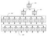
제1급에는 단일 회로 코딩 신호를 접수하는데 사용하는 한개의 NOT 게이트401이 포함된다. 제2급에는 두개의 NOT 게이트가 포함되는 바, 이는 각기 전급 NOT 게이트401과 연결된 NOT 게이트402, NOT 게이트403이며, 단일 회로 코딩 신호를 2로로 나눈다. 제3급에는 16개의 NOT 게이트404가 포함되는 바, 이는 각기 전급 NOT 게이트402와 연결된 제1조의 8개 NOT 게이트, 전급 NOT 게이트403과 연결된 제2조의 8개 NOT 게이트이며, 2로 코딩 신호를 16로로 나눈다. 제4급에는 128개의 NOT 게이트405가 포함되며, 매 8개를 한개 조로 하여 16조로 나눈다. 매 조의 NOT 게이트는 각기 전급의 한개 NOT 게이트와 연결되어 16로 코딩 신호를 128로 코딩 신호로 나눈다.
신호분로 모듈중에서는 단일 회로 코딩 신호를 128로 코딩 신호로 분로한다. 매 로의 코딩 신호에 대해 입력 단자로부터 출력단자까지 모두 제1급의 NOT 게이트로부터 제4급의 NOT 게이트까지 총 4개 NOT 게이트를 거친다. 매개 NOT 게이트의 지연은 동일한 것이므로 입력단자에서 입력한 단일 회로 코딩 신호에 비해 매 로 출력 코딩 신호는 모두 동일한 지연을 경험하였기에 다중 회로 코딩 신호의 분로와 동기화 변조를 실현하였다.In the signal shunt module, a single circuit coded signal is divided into 128 coded signals. For each coded signal, all four input gates go from the input terminal to the output terminal, from the first-class NOT gate to the fourth-class NOT gate. Since the delay of each NOT gate is the same, each output coded signal experienced the same delay compared to the single circuit coded signal inputted from the input terminal, thus achieving shunt and synchronous modulation of the multiple circuit coded signals.
도5는 드라이버 의 구조도이다. 드라이버 에는 구동판 501, 신호 입력 인터페이스 508, 신호 출력 인터페이스 509가 포함된다. 드라이버 102는 진일보로 내부 회로에 전력을 공급하는 전원 인터페이스507과 전원 전환기 502이 포함되어 전력 공급과 전력 차단 스위치 506과 냉각을 제공하는 팬 505를 통제할수 있다.5 is a structural diagram of a driver. The driver includes a driving
전원 전환기 502은 스위치 506과 전원 인터페이스 507이 외부에 연결한 220V 교류 전원을 통해 220V 교류 전기를 30V 직류 전기로 전환하여 구동판 501에 전력을 공급한다.The
구동판 501에는 다수의 LED 구동 유닛이 포함되어 코딩 신호에 근거하여 구동 신호를 발생한다. 신호 입력 인터페이스 508은 다수의 DB9 수 커넥터이고, 신호 출력 인터페이스 509는 다수의 RCA 암 커넥터를 적용하였다. 한개의 실시예 중에서 신호 입력 인터페이스 508에는 4개의 DB9수 커넥터가 포함되고, 구동판 501에는 32개의 LED 구동 유닛이 포함되며, 신호 출력 인터페이스 509에는 32개의 RCA 인터페이스가 포함되어 드라이버 102는 4로 입력 신호로 32개 발광 다이오드를 구동할수 있다.The driving
도6a 내지 6c는 구동판 2101중의 LED 구동유닛 U1의 전기 회로도이다. 한개의 실시예 중에서 LED 구동 유닛 U1은 미국 텍사스주 기기로부터 구매할수 있는 게이트 드라이버 UCC27531DBV를 적용한다. 게이트 드라이버 UCC27531DBV의 이네이블 EN은 5V 직류전기를 연결하고, VDD 단자는 30V 직류전기를 연결하며, GND단자는 접지하고, IN 단자는 입력단자로 하고, OUTH단자는 출력단자로 하며, OUTL단자는 공중연결한다. 콘덴서C4는 5V 직류전기와 대지 사이에 직렬 연결되며, 콘덴서C1, 콘덴서C2, 콘덴서C3은 30V 직류전기와 대지 사이에 병렬 연결된다. 그중, 콘덴서C1의 크기는 1nF이고, 콘덴서C2의 크기는 0.1μF이며, 콘덴서C3의 크기는 10μF이고, 콘덴서C4의 크기는 1μF이다.6A to 6C are electrical circuit diagrams of the LED drive unit U1 in the drive plate 2101. FIG. In one embodiment, the LED drive unit U1 employs a gate driver UCC27531DBV, which is available from Texas, USA. Enabling EN of gate driver UCC27531DBV connects 5V DC, VDD connects 30V DC, GND terminal is grounded, IN terminal is input terminal, OUTH terminal is output terminal, OUTL terminal is Connect in the air. Capacitor C4 is connected in series between the 5V direct current and the earth, and capacitors C1, C2, and C3 are connected in parallel between the 30V direct current and the earth. Among them, the size of the capacitor C1 is 1 nF, the size of the capacitor C2 is 0.1 μF, the size of the capacitor C3 is 10 μF, and the size of the capacitor C4 is 1 μF.
해당 該LED 구동 유닛 U1의 이네이블은 항상 높은 레벨에 처하여 있다. 신호 입력 인터페이스2108에서 다중 회로 코딩 신호를 접수하고, 다중 회로 코딩 신호중의 단일 회로 코딩 신호를 상응한 LED 구동 유닛 U1의 입력단자로 전송하여 코딩 신호를 확대하며, 구동신호로써 출력단자로부터 출력한다.The enable of the LED drive unit U1 is always at a high level. A multi-circuit coded signal is received at the signal input interface 2108, a single-circuit coded signal of the multi-circuit coded signal is transmitted to the input terminal of the corresponding LED drive unit U1 to enlarge the coded signal, and output from the output terminal as a drive signal.
본 발명이 제출한 광신호 발사장치는 동기화 변조와 다수의 가시광선 신호원을 통해 대면적의 광신호 커버를 실현할수 있다. 해당 광신호 발사장치의 인코더 중에서 입력신호에 대해 코딩과 분로 처리를 진행한다. 우선적인 실시예 중에서 직렬한 NOT 게이트를 선택하여 신호분로 모듈을 실현함으로써 매 로 신호가 동일 지연을 경험하게 하며, 다중 회로 코딩 신호의 분로와 동기화 변조를 실현하였다. 해당 광신호는 기존 광통신 시스템의 광신호 커버 범위가 한정된 문제를 해결하여, 일반 LED 조명등을 광원으로 사용하여, 통신과 조명을 일체로 함으로써 구조가 간단하고 쉽게 실현이 가능하다.The optical signal launching device proposed by the present invention can realize a large area optical signal cover through synchronization modulation and multiple visible light signal sources. Coding and shunt processing are performed on the input signal among the encoders of the optical signal launcher. By selecting a NOT gate in series to implement a signal shunt module among the preferred embodiments, each signal experiences the same delay, and shunt and synchronous modulation of multiple circuit coded signals are realized. The optical signal solves the problem that the optical signal cover range of the existing optical communication system is limited, and by using a general LED lighting as a light source, the structure is simple and easy to realize by integrating the communication and lighting.
상기 광신호 발사장치의 구체적인 실시예로서,접근 통제 시스템의 카드형 광 자물쇠--광자카드일수 있다. 도7과 같이 본 발명 광자카드는 비교적 우수한 실시예의 폭발 구조도이다. 광자카드에는 패널 701과 배판702로 구성된 카드식 셀이 포함된다. 즉, 셀 전체는 원각 직사각형 구조를 이루고 있으며, 셀 내부는 공강을 형성하였다. 도7의 상단은 광자카드의 꼭대기 이며, 셀내에 회로판707이 밀봉포장되어 있으며, 회로판707에는 광자카드의 꼭대기 위치에 신분정보가 포함된 광속을 발송하는 발광체가 설치되어 있고, 발광체는 LED조명 704를 우선으로 하며, 해당 LED조명 704는 용접, 접착 등 방식으로 회로판과 전기 연결을 할수 있다. 또한 광자카드 작업상태를 표시하는 지시등 703이 있고, 해당 지시등은 마찬가지로 LED를 적용하여 작업한다. 광자카드에는 또 중간 구역에 위치한 지문 채집 모듈 705이 포함되어 있고, 해당 지문 채집 모듈 705는 회로판707위의 관련 칩 전기회로와 전기연결되어 있으며, 지문 채집 모듈 705와 회로판 707사이에는 또 키 실리카겔 320이 하나 설치되어 있다. 해당 키 실리카겔 320의 역할은 지문 채집 모듈 320에게 누름 스프링 백 효과를 제공함으로써 지문 채집 모듈 705로 하여금 누르지 않을때 회로에 접입하지 않고, 누름을 완성한후 지문 채집 모듈 705로 하여금 스프링을 회복하게 한다.As a specific embodiment of the optical signal launch device, it may be a card type optical lock-photon card of an access control system. As shown in Fig. 7, the photon card of the present invention is an explosive structure diagram of a comparatively superior embodiment. The photon card includes a card type cell composed of a
해당 광자카드를 사용하여 신분 검증을 진행할때, 카드 소지인은 손가락을 지문 채집 모듈 705에 눌러 지문 채집 모듈 705로 하여금 회로를 접입하게 하여 작업을 시작하게 한다. 지문 채집 모듈 705가 채집한 지문 정보는 전기 신호로 전환하고, 회로중의 관련 칩 저장 정보와 비교 검사를 진행하며, 검사 성공후 LED조명 704가 발광하고, 회로판 707위의 관련 칩이 구동하여 카드 소지인 신분정보가 포함된 광속을 발송한다.When performing identity verification using the photon card, the cardholder presses his finger on the
광속에 신분정보가 포함된 방식으로 작업을 하기에 읽기 설비에 접근하지 않고도 신분정보의 발송, 접수를 완성할수 있고, 먼거리 작업을 실현하였다. 특히는 접근 통제 식별에 적용된다.Since the work includes the identification information in the speed of light, it is possible to complete the sending and receiving of the identification information without access to the reading facility and to realize the long distance work. In particular, it applies to access control identification.
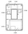
진일보로, 상기 실시예중의 각 부품의 구체적인 구조는 아래 묘사와 같다. 도8은 도7 실시예중의 패널 701의 정면 구조 안내도이다. 판넬은 금속 또는 플라스틱으로 만든 덮개를 덮지 않은 셀이고, 중부에서 직사각형의 통공을 밀링하여 지문 채집 모듈 어댑터 구멍으로 하였다. 형상과 크기는 지문 채집 모듈과 적합하여 지문 채집 모듈이 셀의 표면에 삽입할수 있게 하였다. 패널위에는 또 한개의 비교적 작은 통공을 설치하여 지시등 어댑터 구멍 802로 하고, 형상과 크기는 모두 지시등과 일치하다. 패널위에서 회로판에 대응하는 LED조명의 위치에는 한개의 반원형 돌기 801을 형성하였다. 해당 돌기 801의 역할은 LED 조명을 보호하는 것이다. 도9와 같이 전체 패널위에서 오직 LED 조명의 위치만이 돌기를 형성하였고, 패널의 기타 위치는 비교적 얇은 구조를 유지하고 있어, 전체적인 광자카드의 두께를 감소시켜 카드의 형상과 접근하게 함으로써 휴대하기 편리하다. 이런 구조로 설치한 패널에서 카드 소지인은 한개 키만을 통해 모든 조작을 완성할수 있으며, 조작이 용이하다.Further, the specific structure of each component in the above embodiment is as described below. Fig. 8 is a front structural guide diagram of
바람직하게는 패널의 한개 측면에 도10과 같은 충전구멍 1001을 설치하고, 충전구멍 1001의 형상, 위치는 회로판위의 충전 인터페이스와 적합하다. 충전의 편리를 보증함으로써 카드 소지인으로 하여금 적합한 충전설비를 쉽게 찾을수 있게 하기 위하여, 본 실시예 중에서 충전 인터페이스는 표준화의 USB 인터페이스를 적용하였고, 이에 대응하여 충전구멍 1001도 표준적인 USB 인터페이스의 형상으로 설치하였다.Preferably, a
도11은 본 발명이 제공한 광자카드가 패널을 제거한후의 구조안내도이다. 도11로부터 알수 있듯이, 회로판과 배터리 1105은 셀 내부 공간을 밀접하게 채워 넣어, 전체 공간을 더욱 빈틈없게 하였으며, 회로판위의 다수의 칩 1104는 집중 설치된것이 아니라 회로판위의 부동한 구역에 배치되어 내부 공간 이용율을 최대한 제고시키고, 광자카드의 전체 체적을 감소하였다. 도11에서 회로판의 꼭대기에는 LED 조명1102와 지시등 1101가 배치되었고, 밑단은 USB인터페이스 1103이며, 회로판의 중간 구역, 중간 위치에 대응하는 것은 지문 채집 모듈의 눌림 구역이다. 해당 눌림 구역의 양측에는 각기 칩 1104를 설치하여 전체 회로판위의 소자 부품을 빈틈없이 배열시켰다.11 is a structural guide diagram after the photon card provided by the present invention removes the panel. As can be seen from Fig. 11, the circuit board and the
바람직하게는, 상기 다수의 칩에는 채집한 지문을 암호화 전자파 신호로 전환하는 칩, LED 발광을 구동하는 칩 등이 포함될수 있다.Preferably, the plurality of chips may include a chip for converting collected fingerprints into an encrypted electromagnetic wave signal, a chip for driving LED light emission, and the like.
광자카드의 체적을 최대한 감소하기 위하여, 내부의 회로판과 배터리 1105의 고정방식에 있어서 회로판의 변두리에서 가공하는 것이 아니라 회로판의 패널에서 고정하는 방식을 적용하였다. 도11의 실시예 중에서 회로판과 배터리 1105위의 다수의 위치는 나사못 또는 리벳으로 회로판 및 배터리 1105를 셀의 내부에 고정시키고, 회로판 및 배터리 1105의 변두리는 셀의 안족에 밀착시킨다.In order to reduce the volume of the photon card as much as possible, the method of fixing the internal circuit board and the
본 발명에서 셀의 전체 형상이 내부의 회로판 등 부품과 부합되어 얇은 카드 모양을 형성하였고, 전체 광자카드 두께가 USB인터페이스의 높이와 비슷하므로, 휴대 체험에 있어서 기존의 감응식 카드와 비슷하다. 또한 신분정보가 포함된 광속으로 신분 검증을 진행하기에 조작 거리는 전자 감응식 카드보다 훨씬 멀어 먼거리 신분 검증 우세를 갖추었다.In the present invention, the overall shape of the cell is matched with components such as an internal circuit board to form a thin card shape, and because the total photon card thickness is similar to the height of the USB interface, it is similar to the conventional inductive card in the portable experience. In addition, the identification range is far greater than that of the electronic sensitive card to verify the identity with the luminous flux containing the identity information.
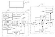
도12는 본 발명의 광제어 자물쇠 시스템의 구조 안내도이다. 이에는 광 열쇠 1201, 스마트 단말 1203과 자물쇠 1202가 포함되고, 광 열쇠 1201에는 포지션 모듈1204, 발광모듈 1207, 메인 컨트롤 모듈 1205, 구동 모듈 1206과 무선통신 모듈1208이 포함된다. 자물쇠에는 광신호 접수모듈 1209, 컨트롤 모듈 1210과 자물쇠 본체 1211이 포함되며, 메인 컨트롤 모듈 1205는 구동 모듈 1206, 구동 발광 모듈 1207를 통제하여 정보가 포함된 광신호를 발사하고, 포지션 모듈 1204는 광 열쇠의 위치 정보를 채집하며, 메인 컨트롤 모듈 1205는 무선통신 모듈 1208이 위치정보를 스마트 단말 1203으로 발송하도록 통제한다. 스마트 단말 1203은 무선통신 모듈 1208가 발사한 위치정보를 접수하고 위치정보를 표시한다. 본 실시예의 광 열쇠 1201는 아동들이 지니는 광 열쇠를 우선으로 하며, 스마트 단말 1203의 사용자는 학부모(및 보호자, 선생님 등)이다. 일종의 실비방법에서 스마트 단말 1203은 휴대폰이고, 학부모는 휴대폰에 표시된 위치도를 통해 아동의 현재 지리적 위치 정보를 획득할수 있다. 무선통신 모듈은 또 광 열쇠와 관련된 기타 정보를 발사할수 있는바, 해당 정보는 광 열쇠 자체 속성의 정보 및 광 열쇠 소지인의 관련 정보 등일수 있다.12 is a structural guide diagram of the light control lock system of the present invention. This includes an optical key 1201, a
도13은 본 발명 광제어 자물쇠 시스템의 광 열쇠, 스마트 단말의 관계 안내도이다. 도12와 도13을 결합하여 일종의 실비방법 중에서 스마트 단말 1302의 무선 접수 발송 모듈 1309은 무선통신 모듈 1307이 발송한 위치정보를 접수하고 이를 통제 처리 모듈 1311으로 보내며, 스마트 단말 1302은 무선 접수 발송 모듈 1309를 포함하는것 외에 또 역사 궤적 모듈(도면중 미 표시)을 포함한다. 역사 궤적 모듈은 통제 처리 모듈 1311과 연결되어 무선통신 모듈1307이 발송한 위치 정보에 근거하여 예정 시간대 내 광 열쇠 1301의 위치의 역사 궤적을 계산한다. 통제 처리 모듈 1311, 통제 표시 모듈 1310은 예정 시간대 내 광 열쇠 1301의 위치의 역사 궤적을 표시한다. 이로써 학부모는 임의 시간대 내 아이의 활동 궤적을 조회할수 있다.Fig. 13 is a relational guide diagram of an optical key and a smart terminal of the light control lock system according to the present invention. 12 and 13, the wireless
일종의 실비방법중, 광 열쇠 1301에는 또 긴급 호출 모듈1304가 포함되고, 긴급 호출 모듈1304는 호출신호를 발생시키는데 사용하며, 메인 컨트롤 모듈 1305는 무선통신 모듈1307을 통제하여 호출신호를 미지 저장한 스마트 단말 1302의 무선 접수 모듈 1309에 보낸다. 통제 처리 모듈 1311은 알람 모듈 1313을 통제하여 긴급 호출 신호에 근거하여 반응하도록 한다. 일종의 실비방법중, 광제어 자물쇠 시스템에는 또 최소 한개의 예비용 이동 단말이 포함되며, 긴급 호출 모듈1304가 작동된후 메인 컨트롤 모듈 1305는 또 미리 저장한 스마트 단말이 긴급 호출 신호에 반응하지 않는 상황에서 무선통신 모듈1307을 통제하여 예비용 이동단말에 호출신호를 발송하게 한다. 일종의 실비방법중, 긴급 호출 모듈1304는 한개의 SOS키로 설정하여, 위험한 상황이 발생할 경우, 아동은 SOS키를 길게 누르기만 하면 미리 설정한 번호를 차례대로 후출하여 그중의 한명 연락인과 연결될때까지 호출한다. 또한 위치정보는 문자 메시지, 위챗, QQ 등 형식으로 학부모에게 발송된다.In a kind of practical method, the optical key 1301 also includes an
일종의 실비방법중, 스마트 단말 1302에는 또 감청 모듈 1312가 포함되고, 광 열쇠 1301에는 또 오디오 채집 모듈 1306이 포함된다. 오디오 채집 모듈 1306은 광 열쇠 1301 예정 범위내의 오디오 정보를 채집하는데 사용하고, 메인 컨트롤 모듈 1305는 무선통신 모듈1307을 통제하여 오디오 정보를 무선 접수 발송 모듈 1309로 발송하며, 통제 처리 모듈 1311는 감청 모듈 1312을 통제하여 오디오 정보에 근거하여 상응한 목소리를 재생하게 한다. 한개의 광 열쇠 1301에 대해 여러개의 스마트 단말을 설정하여 감청관리를 진행하게 함으로써 단일 감청번호 이상으로 연락을 취할수 없는 경우를 방지할수 있다. 일종의 실비방법중, 감청 기능을 가동한후, 스마트 단말 1302를 휴대한 학부모는 광 열쇠 1301 주변 10미터 이내의 목소리를 들을수 있어, 아동이 처한 환경상황을 실시간으로 파악할수 있다.In a kind of actual cost method, the
일종의 실비방법중, 스마트 단말 1302에는 또 안전거리 모듈(도면중 미 표시)이 포함되며, 안전거리 모듈은 메인 컨트롤 모듈 1305까지 연결되어 위치정보에 근거하여 광 열쇠 1301이 예정 거리범위내에 있는지를 판단하고, 광 열쇠 1301이 예정 거리범위를 초과할 경우 알람정보가 발생한다. 예하면, 상점, 광장, 번화한 시내구역, 지하철역 등 사람들이 모이는 장소에서 아이가 안전거리를 벗어나기만 하면 안전거리 모듈은 알람 정보(예하면 스피커 또는 버저 등 발성설비를 통해 알람 재생)를 발생시켜 아이를 잃어버리는 상황을 방지한다. 나이가 어린 아동에 대해서는 안전구역을 스마트 단말 1302를 중심으로 50미터 반경 범위를 설정할수 있고, 나이가 커가면 범위를 점차 확대할수 있다. 집에 있을때에는 안전구역을 스마트 단말을 중심으로 30미터 반경 범위를 설정할수 있으며, 사람들이 많고 복잡한 환경에서는 안전구역을 20미터로 조정할수 있다.Among the actual cost methods, the
일종의 실비방법중, 통제 처리 모듈 1311은 아동이 예정 시간내의 위치정보에 근거하여 아동의 예정 시간내 운동 걸음수를 계산함으로써 표시 모듈 1310을 통제하여 상응한 운동 걸음수 상황을 표시하게 한다. 학부모는 아이의 매일 운동 걸음수 조회를 통해 아이가 운동을 게을리할 때 많이 운동하도록 격려할수 있다.In one kind of actual cost method, the
일종의 실비방법중, 스마트 단말 1302에는 또 걸음수 계산 관리 모듈(도면중 미 표시)가 포함되며, 걸음수 계산 관리 모듈은 통제 처리 모듈 1311에 연결된다. 광 열쇠 1301에는 또 운동 걸음수 계산 모듈(도면중 미 표시)이 포함되며, 운동 걸음수 계산 모듈은 광 열쇠 1301의 휴대자의 예정 시간내의 운동 걸음수를 채집한다. 메인 컨트롤 모듈 1305은 무선통신 모듈 1307를 통제하여 운동 걸음수 정보를 무선 접수 발송 모듈 1309로 발송하게 하며, 통제 처리 모듈 1311은 표시 모듈 1310을 통제하여 상응한 운동 걸음수를 표시하게 한다. 학부모는 아이의 매일 운동 걸음수 조회를 통해 아이가 운동을 게을리 할때 많이 운동하도록 격려할수 있다.Among the actual cost methods, the
일종의 실비방법중, 스마트 단말 1302에는 정보 편집 모듈(도면중 미표시,정보 편집 모듈과 통제 처리 모듈 1311 연결)이 포함되고, 광 열쇠 1301에는 또 오디오 재생 모듈1308이 포함된다. 정보 편집 모듈은 문자정보를 발생하는데 사용하고, 메인 컨트롤 모듈 1305은 무선통신 모듈 1307을 통제하여 문자정보를 무선통신 모듈1307로 발송하게 하며, 오디오 재생 모듈은 문자 정보를 접수하고, 문자정보를 음성으로 전환하여 재생한다. 또는 정보 편집 모듈로 음성정보를 발생시키고, 메인 컨트롤 모듈 1305은 무선통신 모듈1307을 통제하여 음성정보를 무선통신 모듈1307으로 발송하게 하며, 알람 모듈은 음성정보를 접수하고 재생한다.In one kind of actual cost method, the
본 발명의 바람직한 실시예에서 광제어 자물쇠 시스템은 상기 모든 기능을 갖추었다. 이외에 학부모들은 설정을 통해 불필요한 기능을 닫을수 있다.In a preferred embodiment of the present invention, the light control lock system has all the above functions. In addition, parents can close unnecessary functions through configuration.
광 열쇠는 비교적 얇은 카드로 만들수 있는 바, 예하면 학교의 이카통처럼 얇아 아동 및 학생들이 갖고 다니기에 편리하다. 카드 표면에는 상황에 근거하여 "SOS 긴급 구원 청구", "원키 통화", "운동 걸음수 계산" 등 터치 키를 설정하여 아동이 정확하게 분별할수 있게 할수 있다.The optical key can be made into a relatively thin card, for example as thin as a school's Ikatong, which is convenient for children and students to carry around. On the card surface, touch keys such as "SOS Emergency Relief Claim", "One-Key Call", and "Calculation of Exercise Steps" can be set to accurately identify the child.
도14는 본 발명 광제어 자물쇠 시스템의 광 열쇠, 자물쇠의 관계 안내도이다. 포지션 모듈1406과 무선통신 모듈1405외에 광 열쇠 1401에는 또 발광모듈 1407이 포함되며, 발광모듈 1407은 정보가 포함된 광신호를 발사하는데 사용한다. 또한 광 열쇠 1401에는 또 비밀번호 설정 모듈 1403, 메인 컨트롤 모듈 1404, 구동 모듈 1408이 포함된다. 비밀번호 설정 모듈 1403은 잠금 해제 비밀번호를 설정하는데, 터치톤식 정보 입력 모듈 혹은 터치스크린 등 방식이 포함된다. 메인 컨트롤 모듈 1404는 비밀번호 설정 모듈 1403에서 발송한 비밀번호 정보를 접수하여, 비밀번호 정보에 근거하여 코딩 데이터를 형성하고, 그 코딩 데이터를 메인 컨트롤 모듈 1404의 메모리에 저장한다. 구동 모듈 1408은 메인 컨트롤 모듈 1404의 레벨 변조 신호의 제어하에 발광 모듈 1407을 구동하여 정보가 포함된 광신호를 발사하게 한다.Fig. 14 is a guide diagram showing the relationship between the optical key and the lock in the light control lock system according to the present invention. In addition to the
발광모듈 1407는 가시광선 혹은 불가시광선을 발사할 수 있다. 본 실시예에서, 발광모듈 1407은 가시광선을 발사할 수 있는 발광 다이오드로서, 구동 모듈 1408의 구동하에 부단히 고속적으로 반짝이면서 0과 1 신호를 대표하는 광 신호를 형성하기에, 본 발명은 통신과 동시에 조명도 제공한다. 발광 다이오드는 반도체 발광 광원으로서 광도가 높고, 신뢰성이 높으며, 에너지 소모가 낮고, 체적이 작으며, 친환경적일뿐만 아니라, 더 나아가 변조성이 좋고, 감지도 높은 등 장점이 있다.The
자물쇠 1402는 광신호 접수모듈 1409, 자물쇠 본체 1412, 신호 처리 회로303, 마이크로 컨트롤러1410(즉 컨트롤 모듈) 및 화면모듈 1411이 포함된다. 광신호 접수모듈 1409는 광 신호를 접수하고, 자물쇠 본체 1412의 열기 혹은 닫기를 제어한다. 광신호 접수모듈 1409는 광 신호를 접수한 후 광 신호를 전류 신호로 전환한다. 신호 처리 회로 303은 전류 신호를 전압 신호로 전환하고, 동시에 전압 신호를 증폭하여 초기 데이터를 복원해낸다. 마이크로 컨트롤러 1410은 신호 처리 회로 303에서 발송한 전압 신호에 근거하여 자물쇠 본체 1412를 제어한다. 자물쇠 본체 1412는 릴레이, 모터 및 모터와 전동 연결된 자물쇠 래치 등 부품으로 구성되고, 자물쇠 본체 1412는 기존 기술이므로 여기에서 더 설명하지 않는다. 화면모듈 1411은 자물쇠 본체 1412의 열기 혹은 닫기 횟수를 나타낸다.The
비밀 번호 설정모듈 1403은 자물쇠 열기 버튼이 설치되어 있고, 자물쇠 열기 버튼을 누르면 메인 컨트롤 모듈 1404가 자물쇠 열기 버튼의 유발을 받고, 코딩 데이터에 근거하여 레벨 변조 신호를 구동모듈 1408에 발송하고, 구동모듈 1408은 레벨 변조 신호의 제어하에 발광모듈 1407을 구동하여 정보를 포함한 광 신호를 발사한다.The
마이크로 컨트롤러 1410내에는 광 열쇠 1401로부터 전송해 온 데이터와 대조 비교할 수 있는 표준 데이터가 저장되어 있기에, 마이크로 컨트롤러 1410이 광 열쇠 1401이 전송해 온 데이터를 접수후, 해당 데이터를 마이크로 컨트롤러 1410내의 표준 데이터와 비교 대조한다. 만약 마이크로 컨트롤러 1410내의 표준 데이터가 접수된 데이터와 매칭되면, 마이크로 컨트롤러 1410은 자물쇠 본체 1412를 제어하여 자물쇠 열기 동작을 실시한다. 만약 마이크로 컨트롤러 1410이 접수한 데이터가 저장되어 있는 표준 데이터와 매칭되지 않으면, 접수된 데이터가 비밀번호 설정모듈 1403이 설정한 새 비밀번호인지를 판단하고, 만약 새 비밀번호 데이터가 맞다면 이 비밀번호 데이터로 기존의 표준 데이터를 교체하고, 동시에 이 데이터를 표준 데이터로 하여 마이크로 컨트롤러 1410내에 저장하며, 만약 새 비밀번호 데이터가 아니라고 판단하면, 자물쇠를 열지 않는다.Since the
본 실시예에서 제시한 광제어 자물쇠 시스텀을 이용하여, 아동은 광열쇠만 휴대하면, 가장은 실시간으로 아동의 현재 위치 정보, 이동 궤적 정보 등을 파악할 수 있고, 동시에 아동이 처해 있는 환경 주위의 소리를 감청할 수 있으며, 아동의 위치가 설정한 안전 거리를 벗어날 경우 경보를 울리고, 아동이 위험에 부딛쳤을 때 긴급 긴급 호출 기능을 작동할 수 있으며, 필요시 가장과 아동은 통화를 진행할 수 있다. 이런 일련의 실용 기능을 통해, 아동의 안전을 극대적으로 보장하고, 동시에 광 열쇠 관리와 아동 안전 관리를 실현한다. 이 외에, 광 열쇠를 분실했을 경우 GPS 위치 추적을 통해 제때에 광 열쇠를 찾을 수 있으므로써 안전 위험과 경제 손실을 피면한다.Using the light control lock system proposed in this embodiment, the child can grasp the child's current location information, movement trajectory information, etc. in real time by carrying only the optical key, and at the same time, the sound around the environment in which the child is located. The child can be alerted if the child's location is outside the set safety distance, alarm can be activated, the emergency emergency call function can be activated when the child is in danger, and the head of household and child can proceed if necessary. Through this series of practical functions, the safety of children is maximized and at the same time, optical key management and child safety management are realized. In addition, if the optical key is lost, GPS positioning allows the optical key to be found on time, avoiding safety risks and economic losses.
도15는 본 발명 광제어 자물쇠 시스템의 구조설명도이다. 이에는 광 열쇠 1502, 광제어 전자 도어록 1503와 최소 한개의 스마트 단말 1501이 포함된다. 광 열쇠 1502은 LED 광 신호를 출력하고, 광제어 전자 도어록 1503은 이 LED 광 신호를 접수하고 전자 도어록의 열기 혹은 닫기를 판단한다. 광 열쇠 1502의 포지션 모듈1506은 광 열쇠 1502의 위치 정보를 채집한다. 메인 컨트롤 모듈 1504는 通過무선통신 모듈1505를 통해 위치 정보를 스마트 단말 1501에 발송하고, 스마트 단말 1501은 위치 정보를 접수하여 위치 정보를 화면에 나타낸다.15 is a structural diagram of the light control lock system of the present invention. This includes an optical key 1502, an optical control
일종의 실비방법중, 스마트 단말 1501의 무선 접수 발송 모듈은 무선통신 모듈1505가 발송한 위치정보를 접수하여 통제 처리 모듈에 발송하고, 스마트 단말 1501은 무선 접수 발송 모듈외에 이동 궤적 모듈이 포함된다. 이동 궤적 모듈은 통제 처리 모듈과 연결하여, 무선 통신 모듈 1505가 발송한 위치 정보에 근거하여 예정 시간내 광 열쇠의 이동 궤적을 계산하고, 통제 처리 모듈은 화면 모듈을 제어하여 예정 시간내의 광 열쇠 위치의 이동 궤적을 나타낸다. 이와 같이, 가장은 임의의 시간내 아동의 활동 궤적을 조회할 수 있다.Among the actual cost methods, the wireless reception sending module of the
일종의 실비방법중, 광 열쇠는 또한 긴급 호출 모듈이 포함된다. 긴급 호출 모듈은 호출 신호를 생성하고, 메인 컨트롤 모듈 1504는 무선통신 모듈1505를 제어하여 호출 신호를 사전에 저장된 스마트 단말 1501의 무선 접수 모듈에 발송하며, 통제 처리 모듈은 알람 모듈을 제어하여 긴급 호출 신호에 따라 응답하게 한다. 일종의 실비방법중, 광제어 자물쇠 시스템은 또한 최소 한개의 예비 모바일 단말이 포함된다. 긴급 호출 모듈이 작동후, 사전에 저장된 스마트 단말 1501이 긴급 호출 신호에 대해 응답이 없을 경우, 메인 컨트롤 모듈 1504는 또 무선통신 모듈 1505를 제어하여 예비 모바일 단말에 호출 신호를 발송하게 한다. 일종의 실비방법중, 긴급 호출 모듈은 한개의 SOS 버튼을 설정하여, 위험한 상황이 발생했 을 경우, 아동은 SOS 버튼을 길게 누르면, 미리 설정된 연락처에 한명의 연락자와 연결될 때까지 순차적으로 호출한다. 동시에 위치 정보는 멧세지, 위챗, QQ 멧세지 등 형식으로 가장에게 발송된다.Of some sort of practical, the optical key also includes an emergency call module. The emergency call module generates a call signal, and the
일종의 실비방법중, 스마트 단말 1501은 또한 감청 모듈이 포함되고, 광 열쇠는 또한 오디오 채집 모듈이 포함된다. 오디오 채집 모듈은 광 열쇠 예정 범위내의 오디오 정보를 채집하고, 메인 컨트롤 모듈 1504는 무선통신 모듈1505를 제어하여 오디오 정보를 무선 접수 발송 모듈에 발송하며, 통제 처리 모듈은 감청 모듈을 제어하여 오디오 정보에 따라 대응되는 소리를 재생한다. 한개의 광 열쇠에 대하여, 여러개의 스마트 단말 1501을 설정하여 감청 관리를 진행함으로써, 단일 감청 전화 번호가 이상이 발생하여 연락이 안되는 상황을 방지할 수 있다. 일종의 실비방법중, 감청 기능을 작동후, 스마트 단말 1501을 휴대한 가장은 광 열쇠 주위 10 미터이내의 소리를 들을 수 있으므로써 아동이 처한 환경 상황에 대해 실시간 파악할 수 있다.In one kind of practical method, the
일종의 실비방법중, 스마트 단말 1501은 또한 안전 거리 모듈(도면중 미 표시)이 포함된다. 안전 거리 모듈은 메인 컨트롤 모듈 1504에 연결되어, 위치 정보에 근거하여 광 열쇠가 예정된 거리 범위내에 있는지 판단하고, 광 열쇠가 예정된 거리 범위를 벗어났을 경우 알람 정보를 생성한다. 예하면, 쇼핑몰, 광장, 번화가, 지하철역 등 사람이 붐비는 장소에서 일단 아이가 안전 거리를 벗어나면, 안전 거리 모듈은 알람 정보(스피커 혹은 버저 등 발성 장비를 통해 알람 재생) 생성하여 아이가 잃어지는 것을 방지한다. 나이가 어린 아동에 대하여, 안전 구역을 스마트 단말 1501을 중심으로 반경이 50미터 범위내로 설정하고, 나이가 늘어남에 따라 범위를 점차적으로 확장한다. 집에 있을 경우, 안전 구역을 스마트 단말 1501을 중심으로 반경이 100미터 범위내로 설정하고, 사람이 붐비는 번화가 환경일 경우, 안전 구역을 20미터로 설정한다.In a kind of practical method, the
일종의 실비방법중, 통제 처리 모듈은 예정된 시간내의 아동의 위치 정보에 근거하여 예정된 시간내의 아동의 걸음수를 계산해내고, 화면 모듈을 제어하여 대응되는 걸음수 정황을 나타낸다. 가장은 아이의 매일 걸음수를 조회하는 것을 통해 아이가 운동이 부족할 때 아이에게 운동을 많이 하도록 격려할 수 있다.In one kind of actual cost method, the control processing module calculates the number of steps of the child in the predetermined time based on the positional information of the child in the predetermined time, and controls the screen module to display the corresponding step situation. The father can look up the child's daily steps to encourage the child to exercise a lot when she lacks exercise.
일종의 실비방법중, 스마트 단말 1501은 또한 걸음수 계산 관리 모듈(도면중 미 표시)이 포함되고, 걸음수 관리 모듈은 통제 처리 모듈과 연결하며, 광 열쇠는 또한 걸음수 계산 모듈(도면중 미 표시)이 포함되고,걸음수 계산 모듈은 광 열쇠의 휴대자가 예정된 시간내의 걸음수를 채집하고, 메인 컨트롤 모듈 1504는 무선통신 모듈1505을 제어하여 걸음수 정보를 무선 접수 발송 모듈로 발송하며, 더 나아가, 통제 처리 모듈은 화면 모듈을 제어하여 대응되는 걸음수 정황을 나타낸다. 가장은 아이의 매일 걸음수 조회를 통해, 아이가 운동이 부족할 때 아이에게 운동을 많이 하도록 격려할 수 있다.Among the actual cost methods, the
일종의 실비방법중, 스마트 단말 1501은 또한 정보 편집 모듈(도면중 미표시, 정보 편집 모듈은 통제 처리 모듈과 연결)이 포함되고, 광 열쇠는 또한 오디오 재생 모듈이 포함된다. 정보 편집 모듈은 문자 정보를 생성하고, 메인 컨트롤 모듈 1504는 무선통신 모듈1505를 제어하여 문자 정보를 무선통신 모듈1505로 발송하며, 오디오 재생 모듈은 문자 정보를 접수하고, 그 문자 정보를 음성으로 전환하여 재생한다. 혹은, 정보 편집 모듈은 음성 정보를 생성하고, 메인 컨트롤 모듈 1504는 무선통신 모듈1505를 제어하여 음성 정보를 무선통신 모듈1505에 발송하며, 알람 모듈은 음성 정보를 접수하고 재생시킨다. 혹은, 정보 편집 모듈은 또한 이미지 정보(예하면 사진, 그림)를 생성하고, 메인 컨트롤 모듈 1504는 무선통신 모듈1505를 제어하여 이미지 정보를 무선통신 모듈1505에 발송하며, 알람 모듈은 이미지 정보를 접수하여 나타낸다.In one kind of practical method, the
일종의 바람직한 실시예중, 광제어 자물쇠 시스템은 상기의 모든 기능을 구비한다. 이외에, 가장은 설정을 통해 불필요한 기능을 끌 수 있다.In one preferred embodiment, the light control lock system has all of the above functions. In addition, the head settings can turn off unnecessary functions.
광 열쇠는 얇은 카드 모양으로 제작할 수 있다. 예하면 학교의 버스 카드처럼 얇게 제작하여 아동 및 학생들이 휴대가 편리하게 할 수 있다. 그리고 카드의 표면에는 <SOS 긴급 호출>, <원 키 통화>, <걸음수 계산> 등 터치 버튼을 설정하여, 아동으로 하여금 정확히 분별할 수 있게 한다.The optical key can be made into a thin card shape. For example, it can be made as thin as a school bus card, making it convenient for children and students to carry. In addition, touch buttons such as <SOS Emergency Call>, <One-Key Call>, and <Step Counting> are set on the surface of the card so that the child can be discerned correctly.
광 열쇠 1502는 단순히 일정한 주파수로 반짝이는 LED광선을 발사할 수 있고, 이 일정한 주파수로 반짝이는 LED 광선은 자물쇠 잠금 해제 비밀번호를 형성한다. 동시에, 광 열쇠 1502는 또한 사용자의 정보를 접수한 후 이진법 숫자 코드로 전환할 수 있고, 광 열쇠 1502는 해당 이진법 숫자 코드와 대응되는, 일정한 주파수로 반짝이는 LED 광선을 발사하며, 해당 사용자의 정보는 사용자 지문, 사용자 음성, 사용자 동공 정보 등이 될 수 있다. 숫자 코트와 대응되는, 일정한 주파수로 반짝이는 LED 광선을 발사하는 방식을 말하자면, 예를 들어 이진번 숫자 코드중 "1"은 LED 광선 켜짐을 대표하고, "0"은 LED 광선 꺼짐을 대표한다. 바꾸어 말하면, 상기 "1"과 "0"에 대응되는 LED 광선의 상태는 상반 상태일 수도 있다.The optical key 1502 can simply emit a flashing LED beam at a constant frequency, which forms the lock unlock password. At the same time, the optical key 1502 can also receive the user's information and convert it to a binary number code, which in turn fires a flashing LED beam at a constant frequency corresponding to the corresponding binary number code. May be a user fingerprint, a user voice, user pupil information, and the like. Speaking of the manner of firing a flashing LED beam at a constant frequency, which corresponds to the number coat, for example, "1" in binary number code represents LED light on and "0" represents LED light off. In other words, the states of the LED light beams corresponding to "1" and "0" may be opposite states.
광 열쇠 1502의 메인 컨트롤 모듈 1504는 비밀번호 유니트 1507을 제어하여, 광제어 전자 도어록의 비밀번호를 생성한다. 광 열쇠는 또한 자물쇠 잠금해제 비밀번호를 LED 광선 신호로 전환시키는 자물쇠 잠금해제 비밀번호 전환 묘듈 1508, 자물쇠 잠금해제 비밀번호 전환 모듈 1508이 전환시킨 광 신호를 발사하는 LED 광 신호 무선 통신 모듈 13, 그리고 메인 트롤 모듈 1504, 자물쇠 잠금해제 비밀번호 전환 모듈 1508, LED 광 신호 무선 통신 모듈 13 등에 전원을 제공하는 제1전원 모듈 1509가 포함된다.The
그중, 비밀번호 유니트 1507은, 컴파일을 통해 자물쇠 잠금해제 비밀번호를 생성하는 자물쇠 잠금해제 비밀번호 컴파일 모듈, 사전에 입력된 자물쇠 잠금해제 비밀번호를 저장하는 자물쇠 잠금해제 비밀번호 저장 모듈이 포함된다. 본 실시예에서는 두가지 자물쇠 잠금해제 비밀번호 생성 모듈을 설정하여 부동한 자물쇠 잠금해제 방식에 대응한다. 사용자가 사용자 지문, 사용자 음성 등 사용자 정보를 사용할 때, 사용자 정보는 먼저 비밀번호 컴파일 모듈을 통해 이진법 숫자 코드로 전환하고, 그 이진번 숫자 코드는 전환 모듈 1508을 통해 LED 광 신호로 전환한다. 사용자가 내부에 저장된 이진법 숫자 코드를 자물쇠 잠금해제 비밀번호로 사용할 경우, 사용자가 광 열쇠 1502를 작동후, 자물쇠 잠금해제 비밀번호 저장 모듈은 자물쇠 잠금해제 비밀번호 전환 모듈 1508를 통해 저장된 이진법 숫자 코드를 LED 광 신호로 전환한다.Among them, the
특히 본 발명 실시예의 광 열쇠 1502는 단독으로 하나의 설비로 사용할 수 있을 뿐만아니라, 핸드폰, 태블릿 PC 등 자체로 LED 조명을 구비한 설비에 집성하여 사용할 수도 있다.In particular, the
광제어 전자 도어록 1503은 LED 광 신호를 접수하는 광신호 접수 모듈 1511, 컨트롤 모듈과 자물쇠 본체 1510이 포함된다. 컨트롤 모듈은 LED 광신호 접수 모듈 1511이 접수한 LED 광신호를 이진법 데이터로 디코딩하는 광신호 디코딩 모듈 1512, 광신호 디코딩 모듈 1512가 디코딩한 이진법 데이터에 근거하여 광제어 전자 도어록 잠금해제하는 잠금해제 모듈 1514, 그리고 광신호 접수 모듈 1511, 광신호 디코딩 모듈 1512 및 잠금해제 모듈 1514에 전원을 공급하는 제2전원 모듈 1515가 포함되고, 제2전원 1515의 예비 전원 모듈 1513도 포함된다.The light control
본 발명 실시예중, 광제어 전자 도어록 1503은 LED 광신호를 접수후, 그 LED 광신호에 대하여 디코딩을 진행한다. 디코딩 과정은, 우선 LED 광신호를 전류신호로 전환하고, 전류신호가 다시 전압신호로 전환되며, 전압이 고레벨(라이징에지)일 경우, 예하면 5V 혹은 3.3V시 디지털 신호의 라이징에지로 간주하고, 전압이 저레벨(폴링에지)일 경우, 즉 0V시 디지털 신호의 저레벨로 간주하며, 고저 레벌로 구성된 디지털 신호가 맨체스터 디코딩을 거쳐 이진법 데이터를 형성한다. 해당 이진법 데이터가 광제어 전자 도어록 내부에 저장되어 있는 이진법 데이터와 동일한 지에 대해 대조 확인하고, 동일한 정황하에서 광제어 전자 도어록의 잠금을 해제한다.In the embodiment of the present invention, the light control
동시에, 본 발명은 예비 전원 모듈 1513이 설치되어 있다. 광제어 전자 도어록 1503의 모든 작동의 동력원은 전기 에너지이기에, 정전시 광제어 전자 도어록 1503은 사용 의의가 없어진다. 예비 전원 모듈 1513은 축전지 혹은 기타 형식의 축전 모듈이 될 수 있다. 정전시 예비 전원 모듈 1513이 광제어 전자 도어록 모듈에 전원 공급한다. 통전후 예비 전원 모듈 1513은 자동으로 차단되어 전기 에너지를 절약한다.At the same time, the preliminary
본 발명은 광신호를 이용하여 잠금을 제어한다. 사용자가 가시광선 비추는 범위를 볼 수 있기에 LED 광신호를 정확히 발사할 수 있고, 동시에 LED 광신호가 다른 사람에 의해 절취되어 비밀번호가 누설되는 것을 걱정하지 않아도 되므로, 안전성과 사용자 체험을 극대적으로 향상시킨다.The present invention controls the lock using the optical signal. The user can see the visible light range so that the LED light signal can be fired accurately, and at the same time, the LED light signal is not cut off by others and there is no need to worry about leaking the password, which greatly improves the safety and user experience. .
도14와 도15를 대조하면,본 실시예와 실시예 1의 구별점은 주로 광 열쇠 1502와 광제어 전자 도어록 1503의 회로 구조 설계이다. 실시예 2의 비밀번호 유니트 1507에 대하여, 사용자 정보는 우선 비밀번호 컴파일 모듈을 통해 이진법 숫자 코드로 전환되고, 그 이진법 숫자 코드는 다시 전환 모듈 1508을 통해 LED 광신호로 전환되는 것으로 비밀번호의 코딩과 전환 과정을 부각한다. 실시예 1의 비밀번호 설정 모듈은 잠금해제 버튼이 설치되어 있고, 잠금해제 버튼을 누른후, 메인 컨트롤 모듈은 잠금해제 버튼의 유발을 받고, 코딩 데이터에 근거하여 레벨 변조 신호를 구동 모듈에 발송하며, 구동 모듈은 레벨 변조 신호의 제어하에서 발광 모듈을 구동하여 정보를 포함한 광신호를 발사하는 것으로 사용자 의지에 어긋나게 잠금해제되는 것을 방지하는 잠금해제 버튼의 작용을 부각한다. 실시예 2는 또 정전시 예비 전원 모듈 1513이 광제어 전자 도어록에 전원을 공급하고, 통전후 예비 전원 모듈 1513이 자동으로 차단되어 에너지를 절약하는 방식으로 자물쇠 시스템의 정상적인 사용을 보장하는, 제2전원 모듈 1515와 조합하여 사용되는 예비 전원 모듈 1513의 작용을 부각한다.In contrast to Fig. 14 and Fig. 15, the distinction between the present embodiment and the first embodiment is mainly the circuit structure design of the optical key 1502 and the optical control
본 발명의 다른 한 방면에서, 광통신 접수 장치를 제공한다. 광통신 접수 장치는 전술 중의 광통신 발사 장치에 응답하고, 대응되는 동작을 진행한다. 예하면 광제어 자물쇠, 광제어 진열장 등이다. 그 핵심은 내부에 설정된 광전 전환 회로이다.In another aspect of the present invention, an optical communication receiving apparatus is provided. The optical communication reception device responds to the optical communication launch device described above and proceeds with a corresponding operation. Examples include light controlled locks, light controlled showcases, and the like. The key is the photoelectric conversion circuit set inside.
도16은 본 발명의 광전 전환 회로의 회로원리도이다. 본 광전 전환 회로는 1급 증폭 회로 1601, 2급 증폭 회로 1602와 비교 출력 회로 1603이 포함된다. 회로는 주로 광전기 다이오드, 연산 증폭기, 저항, 콘덴서 등 소자부품으로 구성된다.Fig. 16 is a circuit principle diagram of the photoelectric switching circuit of the present invention. This photoelectric switching circuit includes a first
그중, 1급 증폭 회로1601은 단전원 VCC 공급을 받는 연산 증폭기 OA1가 포함되고, 싱글 엔드 작업 방식을 사용한다. 동상 입력단자는 접지하고, 반상 입력단자는 광전류를 접수하고, 출력단자는 Vout1을 출력한다.Among them, the
1급 증폭 회로1601은 또 광전기 다이오드PD, 저항 R1, 콘덴서C1가 포함된다.The first
그중, 광전기 다이오드PD의 양극 단자는 연산 증폭시 OA1의 동상 입력 단자와 연결되고, 동시에 접지하며, 음극 단자는 연산 증폭기 OA1의 반상 입력 단자, 저항 R1의 제1단자 및 콘덴서C1의 제1단자와 연결된다.Among them, the positive terminal of the photoelectric diode PD is connected to the in-phase input terminal of OA1 during operational amplification, and is grounded at the same time, and the negative terminal is connected to the antiphase input terminal of the operational amplifier OA1, the first terminal of the resistor R1 and the first terminal of the capacitor C1. Connected.
저항 R1의 제1단자 및 콘덴서C1의 제1단자는 연산 증폭기OA1의 반상 입력 단자와 연결되고, 저항R1의 제2단자 및 콘덴서C1의 제2단자는 연산 증폭기OA1의 출력 단자와 연결된다.The first terminal of the resistor R1 and the first terminal of the capacitor C1 are connected to the half-phase input terminal of the operational amplifier OA1, and the second terminal of the resistor R1 and the second terminal of the capacitor C1 are connected to the output terminal of the operational amplifier OA1.
1급 증폭 회로1601중, 광전기 다이오드PD는 광신호의 접수하여 전류신호로 전환시킨후 연산 증폭기 OA1에 입력하고, OA1은 저항R1과 콘덴서C1와 함께 트랜스 임피던스 증폭 회로를 구성하여, 전류신호를 전압신호로 변환하고, 전압신호를 2급 증폭 회로 102에 입력한다. 그중, R1의 크기 조절을 통해 전류에서 전압으로의 증폭 배수를 조절하고, C1의 크기 조절을 통해 신호의 리플을 억제한다.In the
바람직한 실시예중, 여러개의 광전기 다이오드 PD로 진열을 구성하여 광전류를 증폭할 수 있다.In a preferred embodiment, the display current can be amplified by configuring the display with several photovoltaic diodes PD.
2급 증폭 회로1602는 단전원 VCC의 공급을 받는 연산 증폭기OA2가 포함되고, 싱글 엔드 작업 방식을 사용한다. 반상 입력 단자는 1급 증폭 회로의 출력 Vout1를 접수하고, 동상 입력 단자는 VCC/2를 접수하며, 출력 단자는 Vout2를 출력한다.The
2급 증폭 회로1602는 또 콘덴서C2 및 저항R2부터 R4까지 포함된다. 콘덴서C2과 저항R3은 직렬로 1급 증폭 회로1601의 출력 단자 Vout1과 연산 증폭기OA2의 반상 입력 단자 사이에 연결되고, 저항R2는 연산 증폭기OA2의 반상 입력 단자와 출력 단자 사이에 연결되며, 저항R4는 전압 VCC/2와 연산 증폭기OA2의 동상 입력 단자 사이에 연결된다.The
2급 증폭 회로1602는 전압 신호의 증폭을 실현한다. 콘덴서C2는 입력된 전압신호에 대하여 고주파수 필터링을 진행하고, C2의 크기 조절을 통해 고주파수 필터링의 차단 주파수와 조도 변화에 대한 감응 속도를 조절한다. 반상 증폭을 사용하여 신호를 증폭하고, 저항R2와 R3의 크기 조절을 통해 이득 시스템을 조절하며, 이득 G=1+R2/R3이다. 저항R4는 평형 저항이고, R4의 크기는 R2와 R3이 병렬 연결후의 저항치이다.The
비교 출력 회로1603은 단전원 VCC의 공급을 받는 연산 증폭기OA3이 포함되고, 싱글 엔드 작업 방식을 사용한다. 반상 입력 단자는 2급 증폭 회로1602의 출력 Vout2를 접수하고, 동상 입력 단자는 비교 전압 Vcompare를 접수하고, 출력 단자는 OUTPUT를 출력한다.The
비교 출력 회로1603는 전압신호의 정형을 실현한다. Vcompare의 조절을 통해 출력 신호의 파형을 조절하고, 정형후의 신호는 프로세서에 출력되어 디지털 신호 처리를 진행한다.The
본 발명의 연산 증폭기를 기반으로 한 광전 전환 회로는 구조가 간단하고, 성능이 우수하고, 원가가 낮으며, 비조준 가시광선 통신과 백광 LED 광통신의 수요를 만족시킨다.The photoelectric conversion circuit based on the operational amplifier of the present invention is simple in structure, excellent in performance, low in cost, and satisfies the needs of non-targeted visible light communication and white light LED optical communication.
도17은 본 발명 광전수신기의 구조설명도이다. 본 광전수신기는 광전 전환 회로와 광 수신 모듈이 포함된다.17 is a structural explanatory diagram of the photoelectric receiver of the present invention. The photoreceiver includes a photoelectric conversion circuit and a light receiving module.
본 광전 전환 회로는 광신호를 접수하고, 그 광신호를 전압신호로 전환한다.The photoelectric switching circuit receives an optical signal and converts the optical signal into a voltage signal.
본 광 수신 모듈은 본 광전 전환 회로가 출력하는 전압신호를 접수한다.The optical receiving module receives a voltage signal output from the photoelectric conversion circuit.
도18은 본 발명의 광제어 자물쇠의 일종의 실시 방법이다. 이에는 광로 모듈과 자물쇠 본체가 포함된다. 광로 본체는 광 열쇠가 발사한 광신호를 접수하고, 그 광신호를 잠금해제 신호로 전환하여 자물쇠 본체의 드라이버에 발사한다. 자물쇠 본체는 자물쇠 래치, 자물쇠 고리와 드라이버가 포함되고, 드라이버는 자물쇠 래치와 연결되어 잠금해제 신호를 접수후 자물쇠 래치를 구동하여 자물쇠 고리에서 빠져 나간다.Fig. 18 shows a method of implementing one kind of light control lock of the present invention. This includes an optical path module and a lock body. The optical path main body receives the optical signal emitted by the optical key, converts the optical signal into an unlock signal, and launches it to the driver of the lock main body. The lock body includes a lock latch, a lock ring and a driver. The driver is connected to the lock latch and receives the unlock signal, and then drives the lock latch to exit the lock ring.
일종의 실비방법중, 광로 모듈은 광신호 수신기와 광신호 전환기가 포함된다. 광신호 수신기는 광 열쇠가 발사한 광신호를 접수한다. 광신호 전환기는 광신호를 잠금해제 신호로 전환하고, 잠금해제 신호는 자물쇠 잠금해제 비밀번호를 포함한다. 자물쇠 잠금해제 비밀번호는 지문, 맥박, 심장 박동, 홍채 등 생물 정보 혹은 문자열 등이 포함된다. 상기의 광신호 수신기와 광신호 전환기는 광전전환기로도 대체 가능하다. 다른 일종의 실시 방법중, 광로 모듈은 또 신호 프로세서가 포함되고, 잠금해제 신호에 대하여 처리하여 그중에 포함된 정보를 획득한다.In one kind of practical method, an optical path module includes an optical signal receiver and an optical signal converter. The optical signal receiver receives the optical signal emitted by the optical key. The optical signal converter converts the optical signal into an unlock signal, and the unlock signal includes a lock unlock password. Unlocked passwords contain biometric information such as fingerprints, pulses, heartbeats, irises, or strings. The optical signal receiver and the optical signal converter may be replaced by a photoelectric converter. In another type of implementation, the optical path module also includes a signal processor and processes the unlock signal to obtain the information contained therein.
본 발명의 광제어 자물쇠는 또 컨트롤러가 포함된다. 컨트롤러는 광신호 전환기에서 발사한 잠금해제 신호를 접수하고, 자물쇠 잠금해제 비밀번호가 정확할 경우, 잠금해제 신호를 자물쇠 본체의 드라이버에 발사한다. 본 발명의 진열장은 또 기타 수신기가 포함된다. 예하면 RF 수신기, 적외선 수신기 등이 포함되어 여러가지 문을 여는 방식을 겸용한다.The light control lock of the present invention also includes a controller. The controller receives the unlock signal emitted by the optical signal converter and, if the lock unlock password is correct, fires the unlock signal to the driver of the lock body. The showcase of the present invention also includes other receivers. For example, RF receivers, infrared receivers, etc. are included to open various doors.
일종의 실비방법중, 광제어 자물쇠는 또 메모리가 포함된다. 메모리는 잠금해제 기록을 저장하고, 그 잠금해제 기록을 서버에 발송한다. 잠금해제 기록은 자물쇠 잠금해제 비밀번호 번호, 잠금해제 시간이 포함되고, 잠금해제 기록은 또 잠금해제한 사람이 등록한 정보가 포함된다. 예하면 성명, 핸드폰 번호, 직위 등이다. 자물쇠 잠금해제 비밀번호 번호는 그 자물쇠 잠금해제 비밀번호를 사용한 사람과 대응할 수 있기에, 사용된 자물쇠 잠금해제 비밀번호의 번호를 조회하면 잠금해제한 사람이 누구인지 알 수 있다. 광제어 자물쇠는 또 무선 발사기가 포함된다. 이는 무선 신호를 발사하여 잠금해제한 사람과 대화 및 피드백을 할 수 있다.Of some sort of practical method, the light control lock also includes a memory. The memory stores the unlock record and sends the unlock record to the server. The unlock record includes the lock unlock password number and the unlock time, and the unlock record also contains information registered by the unlocker. Examples include name, cell phone number, and job title. Since the lock unlock password number can correspond to the person who used the lock unlock password, a query of the used lock unlock password number can reveal who unlocked the lock. The light control lock also includes a wireless launcher. It can fire radio signals to talk and give feedback to the unlocked person.
상기의 광제어 자물쇠는 각종 보안 장소에 사용되어 진열장 등 설비로 사용할 수 있다.The light control lock is used in various security places can be used as a showcase and other facilities.
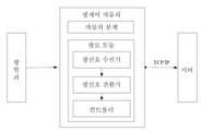
도19는 본 발명 진열장 시스템의 일종의 실시 방법이다. 이는 진열장과 광제어 자물쇠가 포함된다. 광제어 자물쇠는 진열장에 설치된다. 그중, 진열장은 진열장 본체가 포함된다. 광제어 자물쇠는 광로 모듈과 자물쇠 본체가 포함된다. 광로 모듈은 광 열쇠가 발사한 광신호를 접수하고, 그 광신호를 잠금해제 신호로 전환하여 자물쇠 본체의 드라이버에 발사한다. 자물쇠 본체는 자물쇠 래치、자물쇠 고리와 드라이버가 포함된다. 드라이버는 자물쇠 래치와 연결되어, 잠금해제 신호를 접수후 자물쇠 래치를 구동하여 자물쇠 고리에서 빠져 나간다.19 is a method of implementation of the showcase system of the present invention. This includes showcases and light control locks. Light control locks are installed in the showcase. Among them, the showcase includes a showcase body. The light control lock includes an optical path module and a lock body. The optical path module receives the optical signal emitted by the optical key, converts the optical signal into an unlock signal, and launches it to the driver of the lock body. The lock body includes a lock latch, lock ring and screwdriver. The driver is connected to the lock latch, receives the unlock signal and drives the lock latch to exit the lock ring.
본 발명의 광제어 자물쇠는 또 컨트롤러가 포함된다. 컨트롤러는 광신호 전환기에서 발사한 잠금해제 신호를 접수하고, 자물쇠 잠금해제 비밀번호가 정확할 경우, 잠금해제 신호를 자물쇠 본체의 드라이버에 발사한다. 본 발명의 진열장은 또 기타 수신기가 포함된다. 예하면 RF 수신기, 적외선 수신기 등이 포함되어 여러가지 문을 여는 방식을 겸용한다.The light control lock of the present invention also includes a controller. The controller receives the unlock signal emitted by the optical signal converter and, if the lock unlock password is correct, fires the unlock signal to the driver of the lock body. The showcase of the present invention also includes other receivers. For example, RF receivers, infrared receivers, etc. are included to open various doors.
일종의 실비방법중, 본 발명의 진열장 시스템은 또 서버가 포함된다. 이는 광신호 전환기가 발사한 잠금해제 신호를 접수하고, 서버에 사전에 저장된 자물쇠 잠금해제 비밀번호와 비교 대조하여, 자물쇠 잠금해제 비밀번호가 정확할 경우, 잠금해제 신호를 컨트롤러에 출력하고, 컨트롤러는 자물쇠 본체의 드라이버를 구동하고, 진일보로 자물쇠 래치를 구동하여 자물쇠 고리에서 빠져 나간다. 광제어 자물쇠는 또 비교 대조 결과에 근거하여 자물쇠 래치를 자물쇠 고리에서 빠져 나가게 할 것인지를 확정하고, 자물쇠 잠금해제 기록을 서버에 발송한다. 서버는 또 자물쇠 잠금해제 기록을 접수한다. 이상 잠금해제일 경우, 서버는 광 열쇠에 통지하여, 광 열쇠를 진동하게 하고, 광 열쇠상의 경보기가 울리는 등 방식으로 통지한다.In one kind of actual cost method, the showcase system of the present invention also includes a server. It receives the unlock signal that the optical signal converter fired and compares it with the lock unlock password previously stored in the server, and outputs the unlock signal to the controller if the lock unlock password is correct, and the controller Drive the screwdriver and further drive the lock latch to get out of the lock ring. The light control lock also determines whether to release the lock latch from the lock ring based on the comparison result, and sends a lock unlock record to the server. The server also accepts a lock unlock record. In the case of abnormal unlocking, the server notifies the optical key, causes the optical key to vibrate, and notifies the optical key in such a manner as to ring.
일종의 실비방법중, 광로 모듈은 광신호 수신기와 광신호 전환기가 포함된다. 광신호 수신기는 광 열쇠가 발사한 광신호를 접수한다. 광신호 전환기는 광신호를 잠금해제 신호로 전환하고, 잠금해제 신호는 자물쇠 잠금해제 비밀번호가 포함된다. 상기의 광신호 수신기와 광신호 전환기는 광전 전환기로 대체하여 사용할 수 있다. 다른 일종의 실시 방법중, 광로 모듈은 또 신호 프로세서가 포함되고, 잠금해제 신호에 대하여 처리하여 그중에 포함된 정보를 획득한다. 광제어 자물쇠는 또 메모리가 포함된다. 메모리는 잠금해제 기록을 저장한다. 잠금해제 기록은 자물쇠 잠금해제 비밀번호 번호, 잠금해제 시간이 포함된다. 그중 자물쇠 잠금해제 비밀번호 번호는 그 자물쇠 잠금해제 비밀번호를 사용한 사람과 대응할 수 있기에, 사용된 자물쇠 잠금해제 비밀번호의 번호를 조회하면 잠금해제한 사람이 누구인지 알 수 있다. 잠금해제 기록은 서버에만 저장하거나 동시에 광제어 자물쇠와 서버에 저장할 수도 있다.In one kind of practical method, an optical path module includes an optical signal receiver and an optical signal converter. The optical signal receiver receives the optical signal emitted by the optical key. The optical signal converter converts the optical signal into an unlock signal, and the unlock signal includes a lock unlock password. The optical signal receiver and the optical signal converter can be used in place of a photoelectric converter. In another type of implementation, the optical path module also includes a signal processor and processes the unlock signal to obtain the information contained therein. The light control lock also includes a memory. The memory stores the unlock record. The unlock record includes the lock unlock password number and the unlock time. Among them, the lock unlock password number can correspond to the person who used the lock unlock password. Therefore, when the number of the lock unlock password used is inquired, it is possible to know who unlocked the lock password. The unlock record can be stored only on the server or simultaneously on the light control lock and server.
본 발명의 진열장은 여러가지 상품을 전시하거나 판매하는데 사용할 수 있다. 예하면 보석류 진열장, 문물 진열장, 향수 진열장, 귀중품 진열장, 혹은 기타 진열장이다. 본 실시 방법중, 진열장은 보석류 진열장이다.The showcase of the present invention can be used to display or sell various products. Examples are jewelry display cases, cultural display cases, perfume display cases, valuable display cases, or other display cases. In the present method, the showcase is a jewelry showcase.
서버와 진열장은 TCP/IP 프로토콜을 통하여 연결하고, 서버와 진열장은 무선으로도 연결할 수 있다. 예하면 WiFi, 블루투스 등 연결방식이 있다.Servers and showcases can be connected via the TCP / IP protocol, and servers and showcases can also be connected wirelessly. For example, there is a connection method such as WiFi and Bluetooth.
본 발명의 진열장 시스템은 또 광 열쇠가 포함된다. 광 열쇠는 광 발사 장치가 포함되고, 광 발사 장치는 잠금해제 신호를 광신호로 전환시켜 광제어 자물쇠에 발사한다. 잠금해제 신호는 자물쇠 잠금해제 비밀번호가 포함된다. 자물쇠 잠금해제 비밀번호는 지문, 맥박, 심장 박동, 홍채 등 생물 정보 혹은 문자열 등이 포함된다. 광 열쇠가 발사한 비밀번호는 먼저 서버 혹은/와 컨트롤러에 저장되어야 한다. 광 열쇠는 전용설비 혹은 인바디 밴드와 같은 웨어러블 혹은 핸드폰, PAD, 노트북 등과 같은 모바일 전자 설비가 될 수 있다.The showcase system of the present invention also includes an optical key. The optical key includes an optical launch device, which converts the unlock signal into an optical signal to launch the light control lock. The unlock signal includes a lock unlock password. Unlocked passwords contain biometric information such as fingerprints, pulses, heartbeats, irises, or strings. The password fired by the optical key must first be stored on the server and / or controller. The optical key can be a dedicated device or a wearable such as an in-body band or a mobile electronic device such as a cell phone, PAD, notebook or the like.
Claims (17)
Translated fromKorean상기의 다중 회로 코딩 신호를 증폭하여 다중 회로 구동 신호를 생성하는 드라이버;
상기의 다중 회로 구동 신호의 구동하에 동기화된 다중 회로 광신호를 생성하는 여러개 광원을 포함하고,
상기 다중 회로 광신호에 광 통신 발사 장치를 소지하는 소지인의 신분 정보, 위치 정보, 오디오 정보 중 최소한 하나의 정보가 포함되고,
상기 인코더는 :
입력 신호의 아날로그 디지털 전환과 코딩 처리하고, 입력 신호를 단일 회로 코딩 신호로 전환하는 신호 처리 모듈;
단일 회로 코딩 신호를 동기화된 다중 회로 코딩 신호로 전환하는 신호 분로 모듈을 포함하며,
상기의 신호 분로 모듈은 제1급 NOT 게이트의 입력 단자로부터 최후급 NOT 게이트의 대응되는 NOT 게이트의 출력 단자까지, 매 분로 코딩 신호는 동일 수량의 NOT 게이트를 통과하며,
상기의 신호 분로 모듈은 제K급 NOT 게이트의 수량이 제K-1급 NOT 게이트의 수량보다 크고, 동시에, 제K-1급 NOT 게이트중의 매개 NOT 게이트는 제K급 NOT 게이트중의 최소 한개의 NOT 게이트와 연결되며, 그중 K는 2보다 큰 정수인
것을 특징으로 하는 광 통신 발사 장치.An encoder for performing coding and shunt processing on the input signal to generate a synchronized multi-circuit coded signal;
A driver for amplifying the multiple circuit coded signal to generate a multiple circuit drive signal;
A plurality of light sources for generating a multi-circuit optical signal synchronized under the drive of said multi-circuit drive signal,
The multi-circuit optical signal includes at least one of identification information, location information, and audio information of a holder having an optical communication launch device,
The encoder is:
A signal processing module for analog-digital conversion and coding processing of the input signal and converting the input signal into a single circuit coded signal;
A signal shunt module for converting a single circuit coded signal into a synchronized multiple circuit coded signal,
The signal shunt module passes from the input terminal of the first-class NOT gate to the output terminal of the corresponding NOT gate of the last NOT gate, each shunt-coded signal passes through the same quantity of NOT gates,
In the signal shunt module, the number of K-class NOT gates is greater than the K-class NOT gates, and at the same time, the intermediate NOT gates of the K-1 level NOT gates are at least one Connected to the NOT gate of, where K is an integer greater than 2
Optical communication launch device, characterized in that.
상기 입력 신호를 증폭하는 증폭기;
입력된 신호를 디지털 신호로 전환하는 모듈 전환기;
상기의 디지털 신호에 대하여 코딩하여, 단일 회로 코딩 신호를 생성하는 마이크로 컨트롤 유니트를 포함한 신호 처리 모듈을 특징으로 하는 광 통신 발사 장치.The method according to claim 1,
An amplifier for amplifying the input signal;
A module switcher for converting an input signal into a digital signal;
And a signal processing module including a micro control unit for coding the digital signal to generate a single circuit coded signal.
다중의 NOT 게이트 직렬 구조로 되어있는 상기의 신호 분로 모듈을 특징으로 하는 광 통신 발사 장치.The method according to claim 1,
An optical communication launch device characterized in that said signal shunt module has a multiple NOT gate serial structure.
셀;
상기의 셀 내에 밀착된 회로판;
상기의 셀 표면에 감입된 지문 채집 모듈;
상기의 지문 채집 모듈은 상기의 회로판과 연결;
상기의 지문 채집 모듈이 지문을 채집후, 회로판은 상기의 광원을 구동하여 사용자 신분 정보를 포함한 광속을 발사;
상기의 인코더, 드라이버, 광원은 상기의 회로판에 설정되며,
상기 광통신 발사 장치는 광자 카드인 것을 특징으로 하는 광 통신 발사 장치.The method according to claim 1,
Cell;
A circuit board in close contact with the cell;
A fingerprint collection module inserted into the cell surface;
The fingerprint collection module is connected to the circuit board;
After the fingerprint collection module collects a fingerprint, the circuit board drives the light source to emit a light beam including user identification information;
The encoder, driver, and light source are set on the circuit board,
And the optical communication launch device is a photon card.
상기의 광자 카드 작업 상태를 지시하는 지시등이 용접되어 있는 상기의 회로판을 특징으로 하는 광 통신 발사 장치.The method according to claim 4,
An optical communication launch device, wherein said circuit board is welded with an indicator light indicative of said photon card working state.
포지션 모듈과 무선 통신 모듈을 포함하고, 상기의 포지션 모듈은 상기의 광통신 발사 장치의 위치 정보를 채집하고, 상기의 무선 통신 모듈은 상기의 포지션 모듈이 채집한 위치 정보를 발사하는 것을 특징으로 하는 광 통신 발사 장치.The method according to claim 1,
And a position module and a wireless communication module, wherein the position module collects position information of the optical communication launch device, and the wireless communication module launches position information collected by the position module. Communication launch device.
호출 신호를 생성하고 상기의 무선 통신 모듈을 통해 상기의 호출 신호를 발사하는 긴급 호출 모듈을 포함한 것을 특징으로 하는 광 통신 발사 장치.
The method according to claim 6,
And an emergency call module for generating a call signal and firing said call signal via said wireless communication module.
Applications Claiming Priority (13)
| Application Number | Priority Date | Filing Date | Title |
|---|---|---|---|
| CN201520057927.9UCN204463263U (en) | 2015-01-27 | 2015-01-27 | A light control lock and display cabinet system |
| CN201520057927.9 | 2015-01-27 | ||
| CN201520161289.5 | 2015-03-20 | ||
| CN201520163214.0 | 2015-03-20 | ||
| CN201520161289.5UCN204498130U (en) | 2015-03-20 | 2015-03-20 | Photoelectric switching circuit and optical signal receiver |
| CN201520163214.0UCN204517817U (en) | 2015-03-20 | 2015-03-20 | Photoelectric switching circuit and optical signal receiver |
| CN201520317697.5UCN204667496U (en) | 2015-05-15 | 2015-05-15 | The optical key of tool positioning function and light-dependent control lock system thereof |
| CN201520317697.5 | 2015-05-15 | ||
| CN201520341673.3 | 2015-05-25 | ||
| CN201520341673.3UCN204578540U (en) | 2015-05-25 | 2015-05-25 | Optical signal launcher |
| CN201520838691.2UCN205193852U (en) | 2015-10-27 | 2015-10-27 | Photon card |
| CN201520838691.2 | 2015-10-27 | ||
| PCT/CN2016/072351WO2016119702A1 (en) | 2015-01-27 | 2016-01-27 | Optical communication transmitting apparatus and receiving apparatus |
Publications (2)
| Publication Number | Publication Date |
|---|---|
| KR20170108033A KR20170108033A (en) | 2017-09-26 |
| KR102050548B1true KR102050548B1 (en) | 2020-01-08 |
Family
ID=56542434
Family Applications (1)
| Application Number | Title | Priority Date | Filing Date |
|---|---|---|---|
| KR1020177022085AExpired - Fee RelatedKR102050548B1 (en) | 2015-01-27 | 2016-01-27 | Optical communication launching device and receiving device |
Country Status (5)
| Country | Link |
|---|---|
| US (1) | US10116431B2 (en) |
| EP (1) | EP3252970A4 (en) |
| JP (1) | JP6499303B2 (en) |
| KR (1) | KR102050548B1 (en) |
| WO (1) | WO2016119702A1 (en) |
Families Citing this family (9)
| Publication number | Priority date | Publication date | Assignee | Title |
|---|---|---|---|---|
| CN106128361B (en)* | 2016-09-09 | 2018-10-19 | 京东方科技集团股份有限公司 | Optical signal modulation circuit and its modulator approach, array substrate, display panel, display device |
| CN108462987B (en) | 2017-08-07 | 2021-08-27 | 杭州青奇科技有限公司 | Bicycle lock communication system and bicycle lock communication method for sharing bicycles |
| CN108964762B (en)* | 2018-07-23 | 2020-05-29 | 京东方科技集团股份有限公司 | Visible light communication device, driving method thereof, door lock and visible light communication method |
| WO2020035625A1 (en)* | 2018-08-13 | 2020-02-20 | Lightbee, S.L. | System and method for enabling a lock based on wireless optical technology |
| CN109818674B (en)* | 2019-03-25 | 2023-12-15 | 浙江大学城市学院 | A visible light communication wireless broadcast system signal receiving module circuit |
| CN110912608A (en)* | 2019-11-29 | 2020-03-24 | 南昌航空大学 | Single LED-based visible light real-time voice image communication coding system and method |
| CN112929090B (en)* | 2019-12-06 | 2023-12-01 | 青岛海信宽带多媒体技术有限公司 | Optical module and power supply method thereof |
| CN111786733B (en)* | 2020-05-14 | 2021-08-31 | 上海易托邦建筑科技有限公司 | Optical interaction system and optical interaction control method |
| CN115734428B (en)* | 2022-12-28 | 2024-05-31 | 威海中远海运重工科技有限公司 | Constant-power electrodeless dimming control system |
Citations (3)
| Publication number | Priority date | Publication date | Assignee | Title |
|---|---|---|---|---|
| US20040198382A1 (en)* | 2002-10-15 | 2004-10-07 | Hammond Wong | GPS children locator |
| US20070220273A1 (en)* | 2002-06-25 | 2007-09-20 | Campisi Steven E | Transaction authentication card |
| US20080001547A1 (en)* | 2005-09-20 | 2008-01-03 | Negru Sorin L | Driving parallel strings of series connected LEDs |
Family Cites Families (54)
| Publication number | Priority date | Publication date | Assignee | Title |
|---|---|---|---|---|
| JPS5696506A (en)* | 1979-12-28 | 1981-08-04 | Alps Electric Co Ltd | Pulse count detection circuit |
| JPH0385933A (en)* | 1989-08-30 | 1991-04-11 | Oki Electric Ind Co Ltd | Communication system utilizing light wave and radio wave signals combination in transponding device |
| US5825777A (en)* | 1995-05-05 | 1998-10-20 | Creative Integrated Systems, Inc. | Home and small business phone system for operation on a single internal twisted pair line and methodology for operating the same |
| US5530322A (en)* | 1994-04-11 | 1996-06-25 | Lutron Electronics Co., Inc. | Multi-zone lighting control system |
| US6057949A (en)* | 1997-08-07 | 2000-05-02 | The Boeing Company | Bi-directional infrared communications system |
| US6777891B2 (en)* | 1997-08-26 | 2004-08-17 | Color Kinetics, Incorporated | Methods and apparatus for controlling devices in a networked lighting system |
| JPH11177399A (en)* | 1997-12-15 | 1999-07-02 | Mitsubishi Electric Corp | Clock delay circuit, oscillation circuit using the same, phase locked loop circuit, and clock generation circuit |
| US6046550A (en)* | 1998-06-22 | 2000-04-04 | Lutron Electronics Co., Inc. | Multi-zone lighting control system |
| JP3160586B2 (en)* | 1999-04-27 | 2001-04-25 | 松下電子工業株式会社 | CMOS inverter and standard cell using the same |
| AU6729100A (en)* | 1999-08-25 | 2001-03-19 | Hamamatsu Photonics K.K. | Optical receiver and method of support and arrangement thereof |
| US20060059365A1 (en)* | 1999-12-06 | 2006-03-16 | Bsi2000, Inc. | Facility security with optical cards |
| WO2002091311A1 (en)* | 2001-05-04 | 2002-11-14 | Cubic Corporation | Smart card access control system |
| US7200755B2 (en)* | 2001-05-24 | 2007-04-03 | Larry Hamid | Method and system for providing gated access for a third party to a secure entity or service |
| US7598681B2 (en)* | 2001-05-30 | 2009-10-06 | Philips Solid-State Lighting Solutions, Inc. | Methods and apparatus for controlling devices in a networked lighting system |
| US20060067707A1 (en)* | 2004-09-30 | 2006-03-30 | Selvan Maniam | System and method for increasing data communication bandwidth in a light communication system |
| US7097108B2 (en)* | 2004-10-28 | 2006-08-29 | Bellsouth Intellectual Property Corporation | Multiple function electronic cards |
| CA2609877C (en)* | 2005-01-25 | 2015-05-26 | Tir Technology Lp | Method and apparatus for illumination and communication |
| EP1696586A1 (en)* | 2005-02-28 | 2006-08-30 | Sony Deutschland GmbH | Method for wireless optical transmission of data and wireless optical data transmission system |
| JP4692991B2 (en)* | 2005-05-20 | 2011-06-01 | 株式会社中川研究所 | Data transmitting apparatus and data receiving apparatus |
| US7813451B2 (en)* | 2006-01-11 | 2010-10-12 | Mobileaccess Networks Ltd. | Apparatus and method for frequency shifting of a wireless signal and systems using frequency shifting |
| US7723926B2 (en)* | 2006-05-15 | 2010-05-25 | Supertex, Inc. | Shunting type PWM dimming circuit for individually controlling brightness of series connected LEDS operated at constant current and method therefor |
| CN101502013A (en)* | 2006-10-23 | 2009-08-05 | 松下电器产业株式会社 | Optical space transmission system using visible light and infrared light |
| US20080120509A1 (en)* | 2006-11-17 | 2008-05-22 | Simon Rodolphe J | Biometrics-secured transaction card |
| US7928667B2 (en)* | 2006-11-23 | 2011-04-19 | Semisilicon Technology Corp. | Synchronous light emitting diode lamp string controller |
| JP2008136030A (en)* | 2006-11-29 | 2008-06-12 | Matsushita Electric Ind Co Ltd | Clock timing adjustment method and semiconductor integrated circuit |
| KR100866190B1 (en)* | 2007-01-15 | 2008-10-30 | 삼성전자주식회사 | Visible light communication device and method |
| US8011593B2 (en)* | 2007-03-15 | 2011-09-06 | Joseph Frank Preta | Smart apparatus for making secure transactions |
| JP5031427B2 (en)* | 2007-03-30 | 2012-09-19 | 三星電子株式会社 | Visible light transmitter, visible light receiver, visible light communication system, and visible light communication method |
| JP2008271317A (en)* | 2007-04-23 | 2008-11-06 | Sumitomo Chemical Co Ltd | Illumination light communication system and transmitter for illumination light communication |
| JP5161176B2 (en)* | 2008-09-26 | 2013-03-13 | 太陽誘電株式会社 | Visible light communication transmitter and visible light communication system |
| JP5325526B2 (en)* | 2008-10-17 | 2013-10-23 | 三星電子株式会社 | Visible light communication system and visible light communication method |
| US20120299480A1 (en)* | 2009-11-06 | 2012-11-29 | Neofocal Systems, Inc. | System And Method For Current Modulated Data Transmission |
| US8344659B2 (en)* | 2009-11-06 | 2013-01-01 | Neofocal Systems, Inc. | System and method for lighting power and control system |
| US8798479B2 (en)* | 2009-12-03 | 2014-08-05 | Samsung Electronics Co., Ltd. | Controlling brightness of light sources used for data transmission |
| US9317018B2 (en)* | 2010-03-02 | 2016-04-19 | Gonow Technologies, Llc | Portable e-wallet and universal card |
| KR20120054740A (en)* | 2010-11-22 | 2012-05-31 | 주식회사 팬택 | Apparatus and method and method that do send-receive using chrominance information in visible light communication system |
| US9112606B2 (en)* | 2010-12-15 | 2015-08-18 | Electronics And Telecommunications Research Institute | Method and apparatus for transmitting and receiving data using visible light communication |
| US8977569B2 (en)* | 2011-09-29 | 2015-03-10 | Raj Rao | System and method for providing smart electronic wallet and reconfigurable transaction card thereof |
| CN103291149A (en)* | 2012-02-29 | 2013-09-11 | 深圳光启创新技术有限公司 | Method and system for controlling drawer lock through LED lamp |
| CN102800144B (en)* | 2012-07-31 | 2014-12-10 | 深圳光启创新技术有限公司 | Light control door lock convenient for managing user authority |
| CN202918301U (en)* | 2012-11-05 | 2013-05-01 | 北京半导体照明科技促进中心 | Optical receiving module, optical signal processing circuit |
| US8942571B2 (en)* | 2012-12-24 | 2015-01-27 | Industrial Technology Research Institute | Apparatus and method for data embedding in light communication and the light communication system and method thereof |
| EP2755445B1 (en)* | 2013-01-11 | 2020-06-24 | ams AG | Electronic lighting system and method for lighting synchronization |
| JP6267335B2 (en)* | 2013-08-02 | 2018-01-24 | 深▲セン▼光啓智能光子技術有限公司Kuang−Chi Intelligent Photonic Technology Ltd. | Signal transmission method and apparatus |
| CN103795466B (en)* | 2013-08-02 | 2015-11-11 | 深圳光启智能光子技术有限公司 | The transmission method of signal, Apparatus and system |
| CN203911929U (en)* | 2013-11-16 | 2014-10-29 | 深圳光启创新技术有限公司 | Optical signal transmitting apparatus and conference system |
| US20150189714A1 (en)* | 2013-12-30 | 2015-07-02 | Endress+Hauser Conducta Inc. | Sensors with LED Light Sources |
| US10178506B2 (en)* | 2014-03-25 | 2019-01-08 | Osram Sylvania Inc. | Augmenting light-based communication receiver positioning |
| KR101598371B1 (en)* | 2014-07-14 | 2016-02-29 | 브릴리언츠 주식회사 | Smart multi card |
| US9607189B2 (en)* | 2015-01-14 | 2017-03-28 | Tactilis Sdn Bhd | Smart card system comprising a card and a carrier |
| CN204578540U (en)* | 2015-05-25 | 2015-08-19 | 深圳光启智能光子技术有限公司 | Optical signal launcher |
| CN204463263U (en)* | 2015-01-27 | 2015-07-08 | 深圳光启创新技术有限公司 | A light control lock and display cabinet system |
| CN204667496U (en)* | 2015-05-15 | 2015-09-23 | 深圳光启智能光子技术有限公司 | The optical key of tool positioning function and light-dependent control lock system thereof |
| CN204498130U (en)* | 2015-03-20 | 2015-07-22 | 深圳光启智能光子技术有限公司 | Photoelectric switching circuit and optical signal receiver |
- 2016
- 2016-01-27KRKR1020177022085Apatent/KR102050548B1/ennot_activeExpired - Fee Related
- 2016-01-27JPJP2017539644Apatent/JP6499303B2/ennot_activeExpired - Fee Related
- 2016-01-27WOPCT/CN2016/072351patent/WO2016119702A1/enactiveApplication Filing
- 2016-01-27EPEP16742764.0Apatent/EP3252970A4/ennot_activeWithdrawn
- 2017
- 2017-07-27USUS15/661,082patent/US10116431B2/ennot_activeExpired - Fee Related
Patent Citations (3)
| Publication number | Priority date | Publication date | Assignee | Title |
|---|---|---|---|---|
| US20070220273A1 (en)* | 2002-06-25 | 2007-09-20 | Campisi Steven E | Transaction authentication card |
| US20040198382A1 (en)* | 2002-10-15 | 2004-10-07 | Hammond Wong | GPS children locator |
| US20080001547A1 (en)* | 2005-09-20 | 2008-01-03 | Negru Sorin L | Driving parallel strings of series connected LEDs |
Also Published As
| Publication number | Publication date |
|---|---|
| EP3252970A1 (en) | 2017-12-06 |
| EP3252970A4 (en) | 2018-10-24 |
| US20170324539A1 (en) | 2017-11-09 |
| KR20170108033A (en) | 2017-09-26 |
| JP2018511196A (en) | 2018-04-19 |
| WO2016119702A1 (en) | 2016-08-04 |
| US10116431B2 (en) | 2018-10-30 |
| JP6499303B2 (en) | 2019-04-10 |
Similar Documents
| Publication | Publication Date | Title |
|---|---|---|
| KR102050548B1 (en) | Optical communication launching device and receiving device | |
| US11423724B2 (en) | Method and system for activating electronic lockers | |
| WO2015070799A1 (en) | Instruction information transmission and reception methods and devices thereof | |
| EP2862122B1 (en) | System and method for finding an object at distance | |
| US9418530B2 (en) | Wireless safety alert signaling system | |
| CN104488006A (en) | Usb memory device connected with smart phone | |
| CN113746833B (en) | Communication method and device, electronic equipment and storage medium | |
| CN101010652A (en) | Wireless lock | |
| EP2892178A1 (en) | Light signal-based information processing method and device | |
| CN104503374A (en) | Intelligent prompting memo system and method thereof | |
| CN204667496U (en) | The optical key of tool positioning function and light-dependent control lock system thereof | |
| CN203870675U (en) | Campus management system | |
| CN206147684U (en) | System based on cell -phone self external device off -line safety discernment two -dimensional code | |
| CN104392586A (en) | Intelligent key carrying reminding, identity recognition and information record search device and method | |
| CN103824393A (en) | Payment terminal, system for carrying out information interaction based on POS machine and correlation method | |
| CN204215533U (en) | Carrying keys intelligent reminding, identification, information record queries device | |
| CN204761444U (en) | Be applied to mobile communication device of mine | |
| JP6229872B2 (en) | Spatial optical transmission equipment | |
| WO2015070800A1 (en) | Method and device for transmitting and receiving instruction information | |
| CN200986741Y (en) | Remote control system | |
| CN106030480B (en) | The data transmission of touch-screen display | |
| Bianchi et al. | Using mobile device screens for authentication | |
| KR102406624B1 (en) | Apparatus of display for integrated mode transformation | |
| CN206348804U (en) | Bar code data acquisition equipment | |
| CN213987681U (en) | Real-time monitoring system for field operation tools |
Legal Events
| Date | Code | Title | Description |
|---|---|---|---|
| PA0105 | International application | St.27 status event code:A-0-1-A10-A15-nap-PA0105 | |
| A201 | Request for examination | ||
| AMND | Amendment | ||
| E13-X000 | Pre-grant limitation requested | St.27 status event code:A-2-3-E10-E13-lim-X000 | |
| P11-X000 | Amendment of application requested | St.27 status event code:A-2-2-P10-P11-nap-X000 | |
| P13-X000 | Application amended | St.27 status event code:A-2-2-P10-P13-nap-X000 | |
| PA0201 | Request for examination | St.27 status event code:A-1-2-D10-D11-exm-PA0201 | |
| P11-X000 | Amendment of application requested | St.27 status event code:A-2-2-P10-P11-nap-X000 | |
| P13-X000 | Application amended | St.27 status event code:A-2-2-P10-P13-nap-X000 | |
| PG1501 | Laying open of application | St.27 status event code:A-1-1-Q10-Q12-nap-PG1501 | |
| E902 | Notification of reason for refusal | ||
| PE0902 | Notice of grounds for rejection | St.27 status event code:A-1-2-D10-D21-exm-PE0902 | |
| AMND | Amendment | ||
| P11-X000 | Amendment of application requested | St.27 status event code:A-2-2-P10-P11-nap-X000 | |
| P13-X000 | Application amended | St.27 status event code:A-2-2-P10-P13-nap-X000 | |
| E601 | Decision to refuse application | ||
| PE0601 | Decision on rejection of patent | St.27 status event code:N-2-6-B10-B15-exm-PE0601 | |
| AMND | Amendment | ||
| E13-X000 | Pre-grant limitation requested | St.27 status event code:A-2-3-E10-E13-lim-X000 | |
| P11-X000 | Amendment of application requested | St.27 status event code:A-2-2-P10-P11-nap-X000 | |
| P13-X000 | Application amended | St.27 status event code:A-2-2-P10-P13-nap-X000 | |
| PX0901 | Re-examination | St.27 status event code:A-2-3-E10-E12-rex-PX0901 | |
| PX0701 | Decision of registration after re-examination | St.27 status event code:A-3-4-F10-F13-rex-PX0701 | |
| X701 | Decision to grant (after re-examination) | ||
| GRNT | Written decision to grant | ||
| PR0701 | Registration of establishment | St.27 status event code:A-2-4-F10-F11-exm-PR0701 | |
| PR1002 | Payment of registration fee | St.27 status event code:A-2-2-U10-U12-oth-PR1002 Fee payment year number:1 | |
| PG1601 | Publication of registration | St.27 status event code:A-4-4-Q10-Q13-nap-PG1601 | |
| PC1903 | Unpaid annual fee | St.27 status event code:A-4-4-U10-U13-oth-PC1903 Not in force date:20221126 Payment event data comment text:Termination Category : DEFAULT_OF_REGISTRATION_FEE | |
| PC1903 | Unpaid annual fee | St.27 status event code:N-4-6-H10-H13-oth-PC1903 Ip right cessation event data comment text:Termination Category : DEFAULT_OF_REGISTRATION_FEE Not in force date:20221126 |