KR102048647B1 - Ferrule assembly for conduit fitting - Google Patents
Ferrule assembly for conduit fittingDownload PDFInfo
- Publication number
- KR102048647B1 KR102048647B1KR1020187014606AKR20187014606AKR102048647B1KR 102048647 B1KR102048647 B1KR 102048647B1KR 1020187014606 AKR1020187014606 AKR 1020187014606AKR 20187014606 AKR20187014606 AKR 20187014606AKR 102048647 B1KR102048647 B1KR 102048647B1
- Authority
- KR
- South Korea
- Prior art keywords
- conduit gripping
- gripping device
- conduit
- subassembly
- fitting component
- Prior art date
- Legal status (The legal status is an assumption and is not a legal conclusion. Google has not performed a legal analysis and makes no representation as to the accuracy of the status listed.)
- Expired - Fee Related
Links
Images


Classifications
- F—MECHANICAL ENGINEERING; LIGHTING; HEATING; WEAPONS; BLASTING
- F16—ENGINEERING ELEMENTS AND UNITS; GENERAL MEASURES FOR PRODUCING AND MAINTAINING EFFECTIVE FUNCTIONING OF MACHINES OR INSTALLATIONS; THERMAL INSULATION IN GENERAL
- F16L—PIPES; JOINTS OR FITTINGS FOR PIPES; SUPPORTS FOR PIPES, CABLES OR PROTECTIVE TUBING; MEANS FOR THERMAL INSULATION IN GENERAL
- F16L19/00—Joints in which sealing surfaces are pressed together by means of a member, e.g. a swivel nut, screwed on, or into, one of the joint parts
- F16L19/08—Joints in which sealing surfaces are pressed together by means of a member, e.g. a swivel nut, screwed on, or into, one of the joint parts with metal rings which bite into the wall of the pipe
- F16L19/10—Joints in which sealing surfaces are pressed together by means of a member, e.g. a swivel nut, screwed on, or into, one of the joint parts with metal rings which bite into the wall of the pipe the profile of the ring being altered
- F—MECHANICAL ENGINEERING; LIGHTING; HEATING; WEAPONS; BLASTING
- F16—ENGINEERING ELEMENTS AND UNITS; GENERAL MEASURES FOR PRODUCING AND MAINTAINING EFFECTIVE FUNCTIONING OF MACHINES OR INSTALLATIONS; THERMAL INSULATION IN GENERAL
- F16L—PIPES; JOINTS OR FITTINGS FOR PIPES; SUPPORTS FOR PIPES, CABLES OR PROTECTIVE TUBING; MEANS FOR THERMAL INSULATION IN GENERAL
- F16L19/00—Joints in which sealing surfaces are pressed together by means of a member, e.g. a swivel nut, screwed on, or into, one of the joint parts
- F16L19/06—Joints in which sealing surfaces are pressed together by means of a member, e.g. a swivel nut, screwed on, or into, one of the joint parts in which radial clamping is obtained by wedging action on non-deformed pipe ends
- F16L19/061—Joints in which sealing surfaces are pressed together by means of a member, e.g. a swivel nut, screwed on, or into, one of the joint parts in which radial clamping is obtained by wedging action on non-deformed pipe ends a pressure ring being arranged between the clamping ring and the threaded member or the connecting member
- F—MECHANICAL ENGINEERING; LIGHTING; HEATING; WEAPONS; BLASTING
- F16—ENGINEERING ELEMENTS AND UNITS; GENERAL MEASURES FOR PRODUCING AND MAINTAINING EFFECTIVE FUNCTIONING OF MACHINES OR INSTALLATIONS; THERMAL INSULATION IN GENERAL
- F16L—PIPES; JOINTS OR FITTINGS FOR PIPES; SUPPORTS FOR PIPES, CABLES OR PROTECTIVE TUBING; MEANS FOR THERMAL INSULATION IN GENERAL
- F16L19/00—Joints in which sealing surfaces are pressed together by means of a member, e.g. a swivel nut, screwed on, or into, one of the joint parts
- F16L19/06—Joints in which sealing surfaces are pressed together by means of a member, e.g. a swivel nut, screwed on, or into, one of the joint parts in which radial clamping is obtained by wedging action on non-deformed pipe ends
- F16L19/065—Joints in which sealing surfaces are pressed together by means of a member, e.g. a swivel nut, screwed on, or into, one of the joint parts in which radial clamping is obtained by wedging action on non-deformed pipe ends the wedging action being effected by means of a ring
- F—MECHANICAL ENGINEERING; LIGHTING; HEATING; WEAPONS; BLASTING
- F16—ENGINEERING ELEMENTS AND UNITS; GENERAL MEASURES FOR PRODUCING AND MAINTAINING EFFECTIVE FUNCTIONING OF MACHINES OR INSTALLATIONS; THERMAL INSULATION IN GENERAL
- F16L—PIPES; JOINTS OR FITTINGS FOR PIPES; SUPPORTS FOR PIPES, CABLES OR PROTECTIVE TUBING; MEANS FOR THERMAL INSULATION IN GENERAL
- F16L19/00—Joints in which sealing surfaces are pressed together by means of a member, e.g. a swivel nut, screwed on, or into, one of the joint parts
- F16L19/08—Joints in which sealing surfaces are pressed together by means of a member, e.g. a swivel nut, screwed on, or into, one of the joint parts with metal rings which bite into the wall of the pipe
- F16L19/10—Joints in which sealing surfaces are pressed together by means of a member, e.g. a swivel nut, screwed on, or into, one of the joint parts with metal rings which bite into the wall of the pipe the profile of the ring being altered
- F16L19/103—Joints in which sealing surfaces are pressed together by means of a member, e.g. a swivel nut, screwed on, or into, one of the joint parts with metal rings which bite into the wall of the pipe the profile of the ring being altered with more than one ring per pipe end being used
Landscapes
- Engineering & Computer Science (AREA)
- General Engineering & Computer Science (AREA)
- Mechanical Engineering (AREA)
- Quick-Acting Or Multi-Walled Pipe Joints (AREA)
- Joints With Pressure Members (AREA)
- Joints With Sleeves (AREA)
- Automatic Assembly (AREA)
Abstract
Translated fromKoreanDescription
Translated fromKorean본 발명은 액체 또는 가스 유체를 수납하기 위해, 도관과, 다른 유체 구성 요소 사이의, 기계적으로 부착된 접속부를 형성하기 위한 피팅(fitting)에 관한 것이다. 더 구체적으로, 본 발명은 예를 들어 페룰(ferrule)과 같은 2개 이상의 도관 파지 장치를 사용하는 튜브 및 파이프 도관용 피팅에 관한 것이다.The present invention relates to a fitting for forming a mechanically attached connection between a conduit and another fluid component for receiving a liquid or gaseous fluid. More specifically, the present invention relates to tube and pipe conduit fittings using two or more conduit gripping devices, such as, for example, ferrules.
도관과 다른 유체 구성 요소 사이에 기계적 접속부를 형성하기 위한 피팅은 적어도 4개의 부분, 즉 2개의 페룰 및 2개의 피팅 구성 요소를 포함할 수 있다. 미국 특허 제3,250,550호로부터, 자체 확관식(self-flaring) 튜브 커플링의 포지티브 정지부(positive stop)로 함께 압박되는 압축 링과 슬리브 부재 사이의 가압 끼워맞춤(press fit) 접속부를 제공하는 것이 공지되어 있다. 미국 특허 제5,351,998호로부터, 커플링 장치를 위한 밀봉 요소와 유지 요소 사이의 미끄럼 원추면에 접착제를 도포하는 것이 또한 공지되어 있다.The fitting for forming the mechanical connection between the conduit and the other fluidic component may include at least four portions, two ferrules and two fitting components. From US Pat. No. 3,250,550 it is known to provide a press fit connection between the compression ring and the sleeve member which is pressed together by the positive stop of the self-flaring tube coupling. It is. From US Pat. No. 5,351,998 it is also known to apply an adhesive to the sliding cone surface between the sealing element and the retaining element for the coupling device.
본 발명은, 액체 또는 가스 유체를 수납하기 위해, 도관과, 다른 유체 구성 요소 사이의, 기계적으로 부착된 접속부를 형성하기 위한 피팅, 더 구체적으로, 예를 들어 페룰과 같은 2개 이상의 도관 파지 장치를 사용하는 튜브 및 파이프 도관용 피팅을 제공하는 것을 목적으로 한다.The present invention relates to a fitting for forming a mechanically attached connection between a conduit and another fluid component for receiving a liquid or gaseous fluid, more specifically two or more conduit gripping devices such as, for example, ferrules. An object of the present invention is to provide a tube and pipe conduit fitting.
본 명세서에 제시되어 있는 발명들 중 하나의 실시예에 따르면, 피팅 조립체에서 함께 사용되는 2개의 도관 파지 장치는 피팅 조립체로 조립되기 전에 단일 유닛, 카트리지 또는 서브조립체로서 상호 접속되거나 함께 유지된다. 보다 구체적인 실시예에서, 이들 도관 파지 장치 중 하나 또는 양자 모두는 구조체를 포함하며, 도관 파지 장치는 이 구조체에 의해 별개의 서브조립체로서 함께 기계적으로 접속된다. 예를 들어, 일 실시예에서, 튜브 피팅용 전방 페룰 및 후방 페룰은 함께 스냅 연결될 수 있다.According to one embodiment of the inventions presented herein, the two conduit gripping devices used together in the fitting assembly are interconnected or held together as a single unit, cartridge or subassembly prior to assembly into the fitting assembly. In a more specific embodiment, one or both of these conduit gripping devices comprise a structure, the conduit gripping devices being mechanically connected together as separate subassemblies by this structure. For example, in one embodiment, the front ferrule and the rear ferrule for the tube fitting can be snapped together.
본 발명에 따르면, 액체 또는 가스 유체를 수납하기 위해, 도관과, 다른 유체 구성 요소 사이의, 기계적으로 부착된 접속부를 형성하기 위한 피팅, 더 구체적으로, 예를 들어 페룰과 같은 2개 이상의 도관 파지 장치를 사용하는 튜브 및 파이프 도관용 피팅을 얻을 수 있다.According to the invention, fittings for forming a mechanically attached connection between a conduit and another fluid component, for receiving liquid or gaseous fluid, more specifically two or more conduit grips, such as for example ferrules Fittings for tube and pipe conduits using the device can be obtained.
도 1a 및 도 1b는 손으로 단단히 파지한 위치에서 도시되어 있는 본 명세서의 발명들 중 하나 이상의 도관 피팅 조립체의 실시예를 종단면도로 도시하고 있는 도면.
도 2a 및 도 2b는 종방향 절반 단면도로 부분적으로 도시되어 있는 본 명세서의 발명들 중 하나 이상에 따른 피팅용 전방 페룰 및 후방 페룰 보유 구조체의 더 상세한 도면.
도 3은 풀 업(pull-up) 상태 또는 조여진 상태에서의 도 1의 실시예를 도시하고 있는 도면.
도 4a 및 도 4b는 조립된 상태에서의 페룰을 절반 종단면도로 도시하고 있는, 페룰 카트리지 장치의 다른 실시예를 도시하고 있는 도면.
도 5는 풀 업 위치에 있는 피팅에서의 도 4a 및 도 4b의 실시예를 도시하고 있는 도면.
도 6a 및 도 6b는 손으로 단단히 파지한 위치에서의 페룰 카트리지의 다른 실시예를 도시하고 있는 도면.
도 7은 풀 업 위치에서 도 6a의 실시예를 도시하고 있는 도면.
도 8a 및 도 8b는 손으로 단단히 파지한 위치에서의 페룰 카트리지의 다른 실시예를 도시하고 있는 도면.
도 9는 풀 업 위치에서 도 8a의 실시예를 도시하고 있는 도면.
도 10은 손으로 단단히 파지한 위치에서 페룰 카트리지의 다른 실시예를 도시하고 있는 도면.1A and 1B illustrate, in longitudinal cross-sectional view, an embodiment of one or more of the conduit fitting assemblies of the inventions shown shown in a firmly gripped position by hand.
2A and 2B show a more detailed view of a front ferrule and a rear ferrule retention structure for fitting according to one or more of the inventions shown in part in longitudinal half cross-sectional view.
3 illustrates the embodiment of FIG. 1 in a pull-up or tightened state.
4A and 4B show another embodiment of a ferrule cartridge device, showing the ferrule in assembled state in half longitudinal section.
5 shows the embodiment of FIGS. 4A and 4B in the fitting in the pull up position.
6A and 6B illustrate another embodiment of a ferrule cartridge in a firmly gripped position by hand.
FIG. 7 illustrates the embodiment of FIG. 6A in a pull up position.
8A and 8B illustrate another embodiment of a ferrule cartridge in a firmly gripped position by hand.
9 illustrates the embodiment of FIG. 8A in a pull up position.
10 illustrates another embodiment of a ferrule cartridge in a position firmly gripped by hand.
본 명세서의 예시적인 실시예는 스테인레스강 튜브 피팅과 관련하여 제시되어 있지만, 본 명세서의 발명들은 이러한 용례에 한정되는 것은 아니고, 튜브 및 파이프와 같은 다수의 상이한 금속 도관뿐만 아니라 도관, 파지 장치 또는 피팅 구성 요소 또는 이들의 임의의 조합을 위한 상이한 금속을 포함하는 316 스테인레스강 이외의 상이한 재료와 함께 사용하는 것을 발견할 수 있다. 발명들은 액체 또는 가스 유체 시스템을 위해 또한 사용될 수 있다. 본 명세서의 발명들은 도관 파지 장치 및 피팅 구성 요소의 특정 디자인에 대해 예시되어 있지만, 발명들은 이러한 디자인과 함께 사용하는 것에 한정되는 것은 아니고, 적어도 2개의 도관 파지 장치를 사용하는 현재 공지된 또는 이후에 개발될 다수의 상이한 피팅 디자인에서 용례를 발견할 수 있다. 본 출원인은 도관의 외부면 둘레에 밀접하게 수용되고 피팅 구성 시에 이 외부면에 대해 반경방향으로 압축되는 거의 환형인 부재를 지칭하기 위해 용어 "도관 파지 장치"를 사용한다. 용어 "파지"는, 피팅 조립체의 부분적인 풀 업 또는 완전한 풀 업의 결과로서 도관 파지 장치가 도관에 영구적으로 부착되고, 또는 도관 파지 장치가 도관의 표면 내로 컷인(cut-in)하는 것을 반드시 필요로 하는 것은 아니다. 본 출원인은 이에 의해 도관 파지 및 밀봉이 성취되는 수단을 형성하는 다른 부분을 갖거나 갖지 않는 적어도 2개의 도관 파지 장치의 조합을 지칭하기 위해 용어 "페룰 세트"를 사용한다. 모든 피팅 디자인에 필수적인 것은 아니지만, 페룰 세트는 예를 들어 재료, 제조업자, 상관된 디자인 및 기하학적 특징 등에 기초하여 서로에 대해 그리고 피팅 구성 요소에 대해 의도적으로 정합되는 2개의 페룰을 포함하는 것이 통상적이다. 몇몇 피팅에서, 도관 파지 장치에 추가하여, 예를 들어 밀봉부와 같은 하나 이상의 추가의 부분이 존재할 수 있다. 따라서, 용어 "페룰 세트"는 또한 몇몇 실시예에서 완전한 풀 업 후에 페룰 세트가 도관 파지 및 밀봉을 실행하는 하나 이상의 다른 부분을 갖는 하나 이상의 도관 파지 장치를 포함할 수 있다. 발명들은 튜브 또는 파이프와 함께 사용될 수 있고, 따라서 본 출원인은 튜브 또는 파이프 또는 이들 모두를 포함하기 위해 용어 "도관"을 사용한다. 본 출원인은 일반적으로 2개 이상의 도관 파지 장치와 함께 통상적으로 제1 피팅 구성 요소 및 제2 피팅 구성 요소의 조립체를 참조하여 속기로서 용어 "피팅 조립체" 또는 "피팅"을 상호 교환 가능하게 사용한다. 따라서, "피팅 조립체"의 개념은 손으로 단단히 파지한, 부분적인 풀 업 위치 또는 완전한 풀 업 위치에서 도관 상으로의 부분의 조립체를 포함할 수 있지만, 용어 "피팅 조립체"는 또한 예를 들어 선적 또는 취급을 위한 도관이 없는 부분의 조립체뿐만 아니라 함께 조립되지 않더라도 구성부 자체를 포함하는 것으로 또한 의도된다. 피팅은 통상적으로 함께 접합된 2개의 피팅 구성 요소 및 하나 이상의 도관 파지 장치를 포함하지만, 본 명세서의 발명들은 추가의 부품 및 부분을 포함하는 피팅과 함께 사용될 수 있다. 예를 들어, 유니온 피팅(union fitting)은 본체, 4개의 페룰 및 2개의 너트를 포함할 수 있다. 본 출원인은 적어도 1회 조여지거나 완전히 풀 업되고, 이어서 느슨해지고, 이어서 다른 완전한 풀 업 위치로 다시 조여지는 피팅 조립체를 지칭하기 위해 본 명세서에서 용어 "피팅 개조(fitting remake)" 및 파생 구문을 사용한다. 개조는 예를 들어 동일한 피팅 조립체 부분(예를 들어, 너트, 본체, 페룰)에 수행될 수 있고, 또는 피팅 조립체의 부분 중 하나 이상의 교체를 수반할 수 있다. 본 명세서에서 "외향" 및 "내향"이라 함은 편의를 위한 것이며 축방향이 피팅의 중심을 향하는 것(내향) 또는 중심으로부터 이격되는 것(외향)을 간단히 칭한다.Exemplary embodiments herein are presented in connection with stainless steel tube fittings, but the inventions herein are not limited to this application and include conduits, gripping devices or fittings as well as many different metal conduits such as tubes and pipes. It may be found for use with different materials other than 316 stainless steel, including different metals for the components or any combination thereof. The inventions can also be used for liquid or gas fluid systems. While the inventions herein are illustrated with respect to specific designs of conduit gripping devices and fitting components, the inventions are not limited to use with such designs, and are now known or later using at least two conduit gripping devices. Applications can be found in many different fitting designs to be developed. Applicant uses the term “conduit gripping apparatus” to refer to a substantially annular member that is closely received about the outer surface of the conduit and that is radially compressed relative to the outer surface in the fitting configuration. The term “gripping” means that the conduit gripping device is permanently attached to the conduit as a result of a partial pull up or a complete pull up of the fitting assembly, or the conduit gripping device must be cut-in into the surface of the conduit. It is not intended to be. Applicant uses the term “ferrule set” to refer to a combination of at least two conduit gripping devices with or without other portions thereby forming a means by which conduit gripping and sealing are achieved. While not required for all fitting designs, it is common for a ferrule set to include two ferrules that are intentionally matched with each other and with respect to fitting components, for example, based on material, manufacturer, correlated design, and geometrical features. . In some fittings, in addition to the conduit gripping apparatus, there may be one or more additional portions, such as, for example, seals. Thus, the term “ferrule set” may also include, in some embodiments, one or more conduit gripping devices having one or more other portions where the ferrule set performs conduit gripping and sealing after complete pull up. The inventions may be used with tubes or pipes, and therefore Applicant uses the term “conduit” to encompass tubes or pipes or both. Applicants generally interchangeably use the term “fitting assembly” or “fitting” as a shorthand with reference to an assembly of a first fitting component and a second fitting component, typically with two or more conduit gripping devices. Thus, the concept of a "fitting assembly" may include an assembly of parts onto a conduit in a partial pull up position or in a complete pull up position, firmly gripped by hand, although the term "fitting assembly" may also include, for example, shipping Or an assembly of parts without conduits for handling, as well as the component itself, even if not assembled together. While fittings typically include two fitting components and one or more conduit gripping devices joined together, the inventions herein can be used with fittings that include additional parts and portions. For example, a union fitting may comprise a body, four ferrules and two nuts. Applicant uses the term “fitting remake” and derivative phrase herein to refer to a fitting assembly that is tightened at least once or fully pulled up, and then loosened, and then back to another full pull-up position. do. The retrofit may, for example, be performed on the same fitting assembly portion (eg, nut, body, ferrule), or may involve the replacement of one or more of the portions of the fitting assembly. As used herein, "outwardly" and "inwardly" are for convenience and simply refer to the axial direction facing the center of the fitting (inwardly) or away from the center (outwardly).
본 명세서의 발명들의 중요한 특징은, 2개 이상의 도관 파지 장치(예를 들어, 페룰 세트)가, 완전한 피팅을 형성하기 위해 피팅 구성 요소와 유닛의 조립에 앞서, 개별 유닛, 서브조립체 또는 카트리지(25)로서 함께 보유되거나 유지되는 보유 구조체(R)를 제공하는 것이다. "카트리지"라는 것은 불연속적 유닛, 서브조립체 또는 프리조립체(preassembly)로서 함께 보유된 부분의 그룹을 의미한다. 따라서, 본 출원인은 불연속적 구조체와 관련하여 본 명세서에서 용어 카트리지, 유닛, 서브조립체 및 프리조립체를 동의어로 사용한다. 본 출원인은 또한 개별 유닛 또는 자립식 유닛으로서 함께 유지되는 적어도 2개의 페룰 또는 도관 파지 장치로 구성된 유닛 또는 서브조립체를 지칭하기 위해 상호 교환 가능하게 용어 "페룰 카트리지" 또는 "도관 파지 장치 카트리지"를 사용한다. 특히, "페룰 카트리지"는 개별 유닛 또는 서브조립체로서 함께 유지되는 2개 이상의 페룰을 포함하고, 예를 들어 밀봉부와 같은 추가의 부분을 포함할 수 있다. 따라서, 페룰 카트리지는 피팅을 위한 완전한 페룰 세트를 제공할 수 있다.An important feature of the inventions herein is that two or more conduit gripping devices (e.g., sets of ferrules) may be separated into individual units, subassemblies or
다양한 본 발명의 양태, 개념 및 특징이 예시적인 실시예에서 조합되어 구체화되는 것으로서 본 명세서에 설명되고 도시되어 있을 수 있지만, 이들 다양한 양태, 개념 및 특징은 개별적으로 또는 이들의 다양한 조합 및 서브조합으로 다수의 대안적인 실시예에서 사용될 수 있다. 본 명세서에서 명시적으로 배제되지 않으면, 이러한 모든 조합 및 서브조합은 본 발명의 범위 내에 있는 것으로 의도된다. 또한, 본 발명의 다양한 양태, 개념 및 특징 - 대안적인 재료, 구조체, 구성, 방법, 회로, 장치 및 구성 요소, 소프트웨어, 하드웨어, 제어 논리, 형태, 끼워맞춤 및 기능에 대한 대안 등 - 에 대한 다양한 대안적인 실시예가 본 명세서에 설명될 수 있지만, 이러한 설명은 현재 공지되어 있든 이후에 개발되는지간에 이용 가능한 대안적인 실시예의 완전한 또는 배제적인 리스트로 의도되는 것은 아니다. 당 기술 분야의 숙련자들은 본 발명의 양태, 개념 또는 특징 중 하나 이상을 추가의 실시예에 즉시 채택할 수 있고, 이러한 실시예가 본 명세서에 명시적으로 개시되지 않더라도 본 발명의 범위 내에서 사용할 수 있을 것이다. 추가적으로, 본 발명의 몇몇 특징, 개념 또는 양태는 바람직한 장치 또는 방법인 것으로서, 본 명세서에 설명될 수 있지만, 별도로 언급되지 않으면, 이러한 설명은 전술한 특징이 필요하거나 필수적인 것으로 제안되도록 의도되는 것은 아니다. 또한, 본 개시 내용을 이해하는 것을 지원하도록 예시적인 또는 대표적인 값 및 범위가 포함될 수 있지만, 이러한 값 및 범위는 한정적인 개념으로 해석되어서는 안 되고 명시적으로 언급되는 경우에만 임계적인 값 또는 범위로 의도된다. 더욱이, 다양한 양태, 특징 및 개념이 본 발명에 따른 것으로서 또는 본 발명의 부분을 형성하는 것으로서 본 명세서에 명시적으로 식별될 수 있지만, 이러한 식별은 배타적인 것으로 의도되는 것은 아니고, 오히려 이와 같이 또는 특정 발명의 부분으로서 명시적으로 식별되지 않고 본 명세서에 완전히 설명되어 있는 본 발명의 양태, 개념 및 특징이 존재할 수 있고, 발명들은 대신에 첨부된 청구범위에 설명되어 있다. 예시적인 방법 또는 프로세스의 설명은, 모든 경우에 요구되는 것으로서 그리고 모든 단계에 포함되는 것으로서 한정되지 않고, 또한 단계가 제시되는 순서는, 명시적으로 언급되지 않으면 반드시 요구되거나 필요한 바와 같이 구성되어야 하는 것은 아니다.While various aspects, concepts, and features of the invention may be described and illustrated herein as being embodied in combination in exemplary embodiments, these various aspects, concepts, and features may be individually or in various combinations and subcombinations thereof. It can be used in many alternative embodiments. Unless expressly excluded herein, all such combinations and subcombinations are intended to be within the scope of the present invention. In addition, various aspects, concepts, and features of the present invention, including alternative materials, structures, configurations, methods, circuits, devices and components, software, hardware, control logic, forms, fits, and alternatives to functions, etc. Although alternative embodiments may be described herein, this description is not intended to be a complete or exhaustive list of alternative embodiments available, whether currently known or later developed. Those skilled in the art may readily adopt one or more of the aspects, concepts, or features of the present invention in further embodiments, and such embodiments may be used within the scope of the present invention, even if not expressly disclosed herein. will be. In addition, some features, concepts, or aspects of the invention may be described herein as being preferred apparatus or methods, but unless stated otherwise, these descriptions are not intended to suggest that the foregoing features be necessary or essential. In addition, although example or representative values and ranges may be included to assist in understanding the disclosure, such values and ranges should not be construed as limiting concepts and are referred to as critical values or ranges only when expressly stated. It is intended. Moreover, although various aspects, features, and concepts may be expressly identified herein as being in accordance with, or forming part of, the present invention, such identification is not intended to be exclusive, but rather, as such or specific. There may exist aspects, concepts, and features of the invention that are not expressly identified as part of the invention and are fully described herein, and the inventions are described instead in the appended claims. The description of an example method or process is not limited to what is required in every case and as being included in all steps, and the order in which the steps are presented should be configured as required or necessary unless explicitly stated. no.
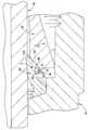
도 1a 및 도 1b를 참조하면, 본 발명들 중 하나 이상의 제1 실시예가 제시된다. 도 1a 및 도 1b에서, 피팅은 종방향 중심선(X)에 대한 종방향 단면도로 도시되어 있다. 본 명세서에서 "반경방향" 및 "축방향"의 모든 참조는, 달리 언급될 수 있는 경우를 제외하고는 X축을 참조한다. 또한, 본 명세서의 모든 각도에 대한 기준은, 달리 언급될 수 있는 경우를 제외하고는 X축을 기준으로 한다. 더욱이, 도면에서 부분들 사이의 다양한 갭 및 간격은 명료화를 위해 또는 축척에 기인하여 다소 과장될 수도 있다.1A and 1B, a first embodiment of one or more of the present inventions is presented. In FIGS. 1A and 1B, the fitting is shown in the longitudinal cross section of the longitudinal center line X. FIG. All references herein to "radial" and "axial" refer to the X axis, except where otherwise noted. Also, references to all angles herein are based on the X axis, except where otherwise noted. Moreover, the various gaps and gaps between the parts in the figures may be somewhat exaggerated for clarity or due to scale.
이 예에서, 튜브 또는 파이프 피팅(10)은 제1 피팅 구성 요소(12) 및 제2 피팅 구성 요소(14)를 포함할 수 있다. 이들 부분은 본체 및 너트로서 각각 당 기술 분야에 통상적으로 알려져 있고, 본체(12)는 도관(18) 단부를 수용하고, 너트(14)는 피팅(10)의 구성 또는 조립 중에 본체(12)에 연결될 수 있다. 본 출원인은 편의상 본 명세서에 통상의 본체 및 너트의 용어를 사용하지만, 당 기술 분야의 숙련자들은 이러한 용어가 부분을 설명하는 데 사용될 수 있는 용례로 발명들이 한정되는 것은 아니라는 것을 이해할 수 있을 것이다. 본체(12)는 도시되어 있는 바와 같이 자립형 구성 요소일 수 있고, 또는 예를 들어 밸브, 탱크 또는 다른 유동 장치 또는 유체 수납 장치와 같은 다른 구성 요소 또는 조립체와 일체형이거나 일체화되거나 조립될 수 있다. 본체(12)는 예를 들자면 당 기술 분야에 잘 알려져 있는 유니온, T자관, 엘보우관 등과 같은 다수의 상이한 구성을 가질 수 있다. 본체(12) 및 너트(14)는 나사산 형성 접속부(16)에 의해 함께 나사식으로 연결되는 것으로서 도시되어 있지만, 나사산 형성 접속부는 모든 용도에 요구되는 것은 아니다. 예를 들어, 몇몇 피팅은 함께 클램핑되는 부분을 갖는다. 피팅은 또한 당 기술 분야에서 통상적으로 수형 피팅 또는 암형 피팅이라 칭하고, 수형 피팅에 대해 수형 본체(12)는 외부 나사산 형성부(16a)를 포함하고 암형 너트(14)는 내부 나사산 형성부(16b)를 포함하는 것으로 구별한다. 암형 피팅(도시되지 않음)에 대해, 수형 너트는 외부 나사산 형성부를 포함하고, 암형 본체는 내부 나사산 형성부를 포함한다. 본 명세서의 실시예는 예를 들어 수형 피팅 실시예를 도시하고 있지만, 본 발명은 암형 피팅 조립체와 함께 사용하기 위해 적절하게 적응될 수 있고 다수의 경우에 임의의 적응을 요구하지 않을 수도 있다.In this example, the tube or pipe fitting 10 may include a first
피팅(10)은 본 명세서의 예시적인 실시예에서 2개 이상의 페룰의 형태로 실현될 수 있는 2개 이상의 도관 파지 장치를 사용하여 도관(18)과 본체(12) 사이에 유체 기밀 접속을 형성하는 데 사용될 수 있다. 그러나, 당 기술 분야에 '페룰'로서 이해될 수 있는 것들 이외의 도관 파지 장치도 또한 본 명세서의 발명들과 함께 사용될 수 있다. 따라서, 본 출원인은 발명들이 당 기술 분야에서 반드시 "페룰"이라 칭할 필요가 없을 수 있는 도관 파지 장치와 함께 사용될 수 있다는 것을 이해하고 상호 교환적으로 용어 도관 파지 장치 및 페룰을 사용한다. 도관 단부(18)는 통상적으로 잘 알려져 있는 바와 같이, 본체(12)의 부분인 반경방향 숄더(19)(도 6a 및 도 6b 참고)에 대해 바닥에 닿는다. 본체(12)는 통상적으로 제1 또는 전방 도관 파지 장치 또는 페룰(24)의 전방부(22)에 접촉하는 테이퍼진 캠밍면(camming surface)(20)을 포함한다. 전방 페룰(24)은 제2 또는 후방 도관 파지 장치 또는 페룰(30)의 전방부(28)에 접촉하는 캠밍면(26)을 그 후방 단부에 포함한다. 캠밍면(26)은 본 명세서에 예시되어 있는 바와 같이 절두 원추형일 수 있지만, 다른 윤곽 및 프로파일이 필요에 따라 사용될 수 있다. 후방 페룰(30)은 너트(14)의 구동면(34)에 접촉하는 피동면(32)을 포함한다. 후방 페룰 전방부는 또한 반경방향 연장 크라운(36)을 포함할 수 있지만, 본 출원인은 또한 크라운의 사용을 필요로 하지 않는 실시예를 본 명세서에 설명한다. 전방 페룰 및 후방 페룰은 도관(18)의 외부면 위에 밀접하게 수용되는 거의 원통형인 내부벽(37, 39)을 포함한다. 후방 페룰은 하나 이상의 반경방향 리세스(39a)를 포함할 수 있다. 본 명세서의 예시적인 실시예는 2개의 도관 파지 장치를 사용하는 피팅 조립체를 예시하고 있지만, 발명들은, 2개 초과의 도관 파지 장치 또는 단지 페룰 또는 도관 파지 장치 이외의 추가의 부분, 예를 들어 추가의 밀봉부를 사용할 수 있는 피팅에 대한 용례가 즉시 발견될 수 있다.The fitting 10 forms a fluid tight connection between the
피팅 커플링 구성 요소(12, 14) 및 도관 파지 장치(24, 30)의 예시적인 기하학적 형상, 구성 및 디자인은 디자인 선택의 문제이고, 사용되는 재료 및 피팅의 예측된 디자인 및 성능 기준에 상당한 정도로 의존할 수 있다는 것을 주목하는 것이 중요하다. 다수의 상이한 커플링 구성 요소 및 도관 파지 장치 디자인이 당 기술 분야에 공지되어 있고 미래에 설계될 수도 있다. 예시적인 실시예와 관련하여 본 명세서에 설명되고 예시되어 있는 본 발명의 개시 내용 및 발명들은 그 후에 피팅 조립체를 형성하기 위해 하나 이상의 피팅 구성 요소와 연결될 수 있는 불연속적 서브조립체 또는 카트리지로서 적어도 2개의 도관 파지 장치를 함께 보유하는 구조체 및 방법에 관한 것이다.Exemplary geometries, configurations, and designs of the
용어 "완전한 풀 업"은, 본 명세서에 사용될 때, 하나 이상의 도관 파지 장치가 변형될 수 있게 하면서도 일반적으로 도관(18) 상의 피팅 조립체(10)의 유체 기밀 밀봉 및 파지를 달성하기 위해 반드시 소성 변형될 필요는 없는 피팅 구성 요소를 함께 연결하는 것을 칭한다. 양 도관 파지 장치는 도관을 영구적으로 파지할 수 있지만 또는 단지 하나만이 도관을 영구적으로 파지할 수 있거나 또는 어느 것도 완전한 풀 업 후에 도관을 영구적으로 파지하지 않을 수 있다. 본 명세서에 사용될 때 "부분적인 풀 업"은, 도관에 대해 반경방향으로 압축되어 도관을 파지하기 위해 도관 파지 장치가 변형될 수 있게 하면서도 완전한 풀 업 후에 성취되는 유체 기밀 접속 또는 요구되는 도관 파지를 반드시 달성할 필요 없이 수형 피팅 구성 요소 및 암형 피팅 구성 요소가 충분한 함께 조여지면서도 완전히 풀 업되지 않은 것을 지칭한다. 따라서, 용어 "부분적인 풀 업"은, 피팅 조립체를 형성하기 위해 제2 피팅 구성 요소와 정합하기 전에 페룰 및 너트가 도관 상에 보유되도록 충분하게 스웨이징(swaging) 공구가 도관 상에 페룰을 변형하는 데 사용되는 예비 스웨이징이라 당 기술 분야에서 종종 칭해지는 것을 포함하는 것으로 또한 이해될 수 있다. 손으로 단단히 파지한 위치(FTP)는, 도관 상에 축방향으로 접촉하지만 느슨하게 조립되어 있는 피팅 구성 요소 및 도관 파지 장치를 지칭하고, 피팅 구성 요소 및 도관 파지 장치는 일반적으로 소성 변형 또는 반경방향 압축을 경험하지 않는 도관 파지 장치 또는 장치들에 의해 예시되는 수형 피팅 구성 요소 및 암형 피팅 구성 요소 양자의 임의의 상당한 조임 없이 서로 접촉하여 적절하게 배열된다. 다수의 피팅 디자인, 특히 회전에 의해 풀 업되는 피팅에서, 손으로 단단히 파지한 위치에서의 피팅부의 축방향 접촉은 풀 업 작동을 위한 정확한 시작점을 보장하기 위해 바람직할 수 있다.The term “complete pull up”, as used herein, is not necessarily plastic deformation to achieve fluid tight sealing and gripping of the
본 출원인은 2개 이상의 도관 파지 장치가 개별적인 별개의 구성 요소로서 제조되고 개별적인 별개의 구성 요소로 남아 있는 개념에서 카트리지 또는 프리조립체(25)의 연접 특성을 설명하기 위해 "불연속적"이라는 용어를 사용하지만, 본 명세서의 발명들에 따르면 이들 부분은 별개의 카트리지, 서브조립체 또는 프리조립체로서 함께 유지되고, 또한 조립 후에 또는 심지어 완전한 풀 업 후에 부분들은 별개로 남아 있고, 필요하다면 이들의 구성적인 개별 부분으로 분해될 수도 있다. 따라서, 용어 "불연속적" 또는 "연접된"은 2개의 도관 파지 장치가 서로 부착되거나 서로 일체로 제조되고 몇몇 디자인에서 완전한 풀 업 또는 부분적인 풀 업 중에 서로로부터 분리되거나 탈착될 수 있는 피팅 디자인으로부터 구별하기 위해 본 명세서에 사용된다. 다음에 불연속형 구조체에서, 본 명세서에 사용되는 바와 같이, 2개 이상의 도관 파지 장치는 재료의 파괴, 전단 또는 다른 분리를 필요로 하지 않고 부분적인 풀 업 또는 완전한 풀 업 중에 서로로부터 해제되고, 분리되거나 또는 다른 방식으로 분리 가능해질 수 있다. 그러나, 본 명세서의 카트리지 또는 서브조립체 실시예의 일부에서, 접착제가 보유 구조체의 부분으로서 사용될 수 있다. 카트리지로서의 초기 조립에도 불구하고, 도관 파지 장치는 개별적으로 설계되는 것으로서 실시되고, 보유 구조체는 풀 업 중에 도관 파지 장치의 작동 및 성능과 간섭하지 않는다. 용어 "불연속적" 또는 "연접된"은 2개 이상의 도관 파지 장치가 별개의 서브조립체로서 함께 느슨하게 또는 대안적으로 꼭 맞게 유지될 수 있다는 사상을 광범위하게 포함하도록 또한 의도된다. 용어 "접속" 및 그 변형은, 불연속적 카트리지(25)에 대해 본 명세서에 사용될 때 도관 파지 장치가 초기에 개별적으로 별개인 따로따로의 부분으로서 형성되거나 제조되고, 다음에 피팅 조립체(10)를 형성하기 위해 피팅 구성 요소(예를 들어, 너트 및 본체)와 용이하게 연결될 수 있게 하기 위해 카트리지 또는 서브조립체로서 불연속적 방식으로 함께 유지되지만, 도관 파지 장치는 보유 구조체(R)로부터 간섭 없이 이들의 예측된 형태, 끼워맞춤 및 기능을 보유할 수 있다는 것을 의미한다.Applicant uses the term “discontinuous” to describe the contiguous nature of the cartridge or
도 1a는 손으로 단단히 파지한 위치에서 피팅(10)을 도시하고 있는데, 즉 다양한 부분(12, 14, 24, 30)이 도관(18) 상에 서로 축방향 접촉하여 조립되어 있지만 이는 기껏해야 너트(14) 및 본체(12)를 함께 연결함으로써 느슨하게 조립되거나 약간 조여지거나 꼭 맞게되는 것을 의미한다.FIG. 1A shows the fitting 10 in a firmly gripped position by hand, ie the
완전한 도관 파지 및 밀봉을 실행하기 위해, 너트 및 본체는 함께 조여져서 - 통상적으로 당 기술 분야에 피팅을 풀 업 하거나 또는 위로 당기는 것 그리고 파생 구문으로서 알려져 있음 - 후방 페룰(30) 및 전방 페룰(24)이 이들의 각각의 캠밍면(26, 20)에 대해 축방향으로 전진하게 된다. 이는 도관 파지 및 밀봉을 실행하기 위해 도관(18)의 외부면에 대한 페룰의 반경방향 내향 압축을 발생시킨다. 전방 페룰(24)의 외부 원추면(24a)은 본체 캠밍면(20)에 접촉하고, 후방 페룰의 접촉면(30a)은 전방 페룰(24)의 캠밍면(26)에 접촉한다. 손으로 단단히 파지한 위치에서, 접촉면(30a)은 캠밍면(26)과 선 접촉을 형성할 수 있지만, 당 기술 분야의 숙련자들은 풀 업 중에 후방 페룰의 전방부의 더 큰 표면적이 일반적으로 또한 캠밍면(26)에 접촉할 수 있고, 따라서 접촉면(30a)은 조립 및 풀 업 중에 캠밍면(26)과 접촉하게 될 수 있는 후방 페룰의 전방부의 임의의 부분을 포함한다는 것을 용이하게 이해할 수 있을 것이다. 접촉면(30a)은 필요에 따라 절두 원추형, 테이퍼형일 수 있고 또는 다른 프로파일 및 윤곽을 가질 수 있다. 본 명세서의 예시적인 피팅 조립체에서, 도관 파지부는 후방 페룰로 주로 성취되고, 전방 페룰은 주로 유체 기밀 밀봉부를 제공한다. 그러나, 몇몇 디자인에서, 전방 페룰은 또한 도관을 파지할 수 있고 후방 페룰은 유체 기밀 밀봉부를 또한 제공할 수 있다. 따라서, 용어 "도관 파지 장치"는 특정 도관 파지 장치가 이들 기능 중 하나 또는 모두를 수행하는지 여부에 무관하게 2개의 별개의 기능, 즉 도관 파지 및 밀봉을 제공할 수 있다. 본 발명은 대안적으로 2개 초과의 도관 파지 및 밀봉 장치를 사용하는 피팅과 함께 사용될 수 있다.In order to effect complete conduit gripping and sealing, the nut and body are tightened together-commonly known in the art as pulling up or pulling up a fitting and as a derivative phrase-the
본 발명의 범위를 한정하는 것은 아니지만, 본 명세서의 예시적인 피팅 디자인은 잘 알려져 있고, 이어지는 것을 제외하고는, 미국 오하이오주 솔론 소재의 스웨이지락 컴퍼니(Swagelok Company)로부터 상업적으로 입수 가능하다. 이들 실시예에서, 페룰은, 페룰이 개별 유닛으로서 함께 유지될 수 있게 하는 페룰 카트리지 특징부 또는 보유 구조체(R)를 포함한다.While not limiting the scope of the invention, the exemplary fitting designs herein are well known and, except as follows, are commercially available from Swagelok Company, Solon, Ohio. In these embodiments, the ferrule includes ferrule cartridge features or retention structures R that allow the ferrules to be held together as separate units.
페룰 카트리지 보유 구조체(R) 이외의 본 명세서에 도시되어 있는 부분(12, 14, 24, 40)은 또한 본 명세서에 참조로서 완전히 포함되어 있는 미국 특허 제5,882,050호 및 제6,629,708호를 비롯하여 다수의 허여되고 계류중인 특허 출원들에 더 설명되어 있다. 본 명세서의 피팅은 이러한 특허에 설명되어 있는 바와 같이 작동할 수 있지만, 카트리지형 방식으로 도관 파지 장치를 함께 보유하기 위한 불연속적 카트리지, 서브조립체 또는 프리조립체를 제공하기 위해 본 명세서에 설명된 바와 같이 수정된다. 페룰 카트리지 개념을 위한 보유 구조체는 기본 피팅 디자인 및 작동의 형태, 끼워맞춤 및 기능을 변경하지 않는 것이 바람직하다.
본 명세서에 개시된 본 발명의 개념의 개요로서, 바람직하지만 모든 경우에 반드시 필요하지는 않은 불연속적 페룰 카트리지 보유 구조체를 위한 다수의 특징이 존재한다. 이들 특징은 몇몇 용례에서 어느 것이 전체 피팅 성능에서 큰 중요성을 가질 수 있는지에 대한 절충안을 수반할 수 있고 이하의 설명으로부터 명백할 수 있는 바와 같이 사용될 수 있다. 이 리스트는 모든 특징의 배제적인 리스트인 것으로 의도되지 않고, 본 명세서에 설명된 것들 중 하나 이상은 특정 용례에 대해 현저하거나 요구되지 않을 수 있다.As an overview of the inventive concepts disclosed herein, there are a number of features for discrete ferrule cartridge retention structures that are preferred but not necessarily necessary in all cases. These features may involve some compromises as to which may have great importance in overall fitting performance and may be used as will be apparent from the description below. This list is not intended to be an exclusionary list of all features, and one or more of the ones described herein may not be prominent or required for a particular application.
일 특징은 본 출원인이 적당하게 강인한 접속 또는 RRC(Reasonably Robust Connection)라 칭한다. 본 출원인은, RRC가, 피팅 조립체를 형성하기 위해 피팅 구성 요소와 서브조립, 목록 작성 및 후속의 조립 중에 개별적으로 또는 일괄적으로 정상적인 취급으로부터 접속된 도관 파지 장치가 용이하게 이격되게 되지 않을 수 있도록 보유 구조체가 설계되는 것을 의미하도록 하려는 의도이다. 용어 "정상" 및 "용이하게"는, 본 명세서에 사용될 때 페룰 카트리지가 사용 중에 이격되지 않는 정도는 디자인 선택의 문제라는 것을 의도적으로 나타낸다. 그러나, 이들 용어를 더 양호하게 이해하기 위해, 본 출원인은 페룰 카트리지의 제조, 조립 및 사용 전체에 걸쳐 예측되거나 발생할 가능성이 있을 수 있는 페룰 카트리지의 임의의 취급으로서 "정상" 취급을 고려한다. 이는 제조 요원, 목록 작성 요원, 선적 요원 및 최종 사용자에 의한 취급을 포함할 수 있다. 이러한 정상 취급 중에, 페룰 카트리지는 도관 파지 장치를 느슨하게 또는 심지어 별도로 두드리는 경향이 있을 수 있는 힘에 노출될 수 있는 것으로 예측될 수 있다. 예를 들어, 페룰 카트리지는 다양한 설치 또는 제조/조립 단계에서 몇 피트 또는 수 피트로부터 딱딱한 물체 또는 표면으로 또는 딱딱한 바닥 상으로 우연히 낙하할 수도 있다. 설계자는 페룰 카트리지가 필요에 따라 부분으로의 손상 또는 분리 또는 느슨해짐 없이 견딜 수 있는 힘의 레벨을 결정할 수 있다. 따라서, 정상 취급은 도관 파지 장치를 분리하기 위해 의도적으로 시도하는 과잉의 또는 손상적인 힘의 사용을 포함하지 않을 것이다. 그러나, 설계자는 이와 같이 요구되면 적절한 공구 및 절차를 사용하여 부분을 분리하는 것이 가능한 옵션을 용이하게 하도록 선택할 수 있다. 달리 말하면, 설계자는 얼마나 용이하게 페룰 카트리지가 그 구성부로 분해될 수 있는지를 결정하기 위한 옵션을 갖는다. 몇몇 용례에서, 페룰 카트리지는 구성부의 하나 이상을 손상시키지 않고 분리될 수 없고 다른 디자인에서 페룰 카트리지는 간단한 손의 힘으로 그리고 그 사이에 이용 가능한 광범위한 "용이성"으로 분해될 수 있도록 설계될 수 있다.One feature is referred to by Applicant as a reasonably robust connection or RRC (Reasonably Robust Connection). The Applicant has established that the RRC may not allow the conduit gripping apparatus to be easily spaced apart from normal handling individually or collectively during subassembly, listing and subsequent assembly with the fitting component to form the fitting assembly. It is intended to mean that the retention structure is designed. The terms "normal" and "easily" when used herein intentionally indicate that the degree to which the ferrule cartridge is not spaced in use is a matter of design choice. However, to better understand these terms, Applicant contemplates "normal" handling as any handling of ferrule cartridges that may be predicted or likely to occur throughout the manufacture, assembly, and use of ferrule cartridges. This may include handling by manufacturing personnel, inventory agents, shipping agents, and end users. During this normal handling, it can be expected that the ferrule cartridge may be exposed to forces that may tend to loosen or even knock the conduit gripping device separately. For example, ferrule cartridges may accidentally fall from a few feet or feet to a hard object or surface or onto a hard floor in various installation or manufacturing / assembly steps. The designer can determine the level of force that the ferrule cartridge can withstand without damage or separation or loosening into parts as needed. Thus, normal handling will not include the use of excessive or damaging forces that are intentionally attempted to separate the conduit gripping device. However, the designer may choose to facilitate the option of separating parts using appropriate tools and procedures, if so desired. In other words, the designer has the option to determine how easily the ferrule cartridge can be disassembled into its components. In some applications, the ferrule cartridge cannot be removed without damaging one or more of its components and in other designs the ferrule cartridge can be designed to be disassembled with a simple hand force and with a wide range of "ease" available therebetween.
불연속적 카트리지 구성 요소의 용이한 분리의 양태는 또한 페룰 카트리지를 설명하는 상황에서 사용될 때 용어 결합 해제, 해제 또는 분리 및 이들의 파생 형태를 발생시킨다. 본 출원인은 2가지 상황에서 상호 교환 가능하게 이들 용어를 사용한다. 제1 상황은 접속된 페룰 또는 도관 파지 장치의 피팅 내로의 설치에 앞서 수행될 때 그 구성부로의 페룰 카트리지의 분리 또는 분해이다. 다른 상황에서, 본 출원인은 피팅 조립체의 풀 업 중에 발생할 수 있는 보유 구조체로부터의 페룰의 결합 해제, 분리 또는 해제를 지칭한다. 이제, 이 후자의 상황에서, 피팅은 풀 업되고 따라서 페룰은 서로로부터 사실상 분리되지 않으며, 실제로 도관을 변형시키고 파지하기 위해 축방향으로 함께 구동된다. 그러나, 본 출원인은 보유 구조체가 더 이상 페룰을 함께 유지하지 않는 것을 설명하기 위해 풀 업 중에 보유 구조체로부터 해제 또는 분해될 때의 페룰 또는 페룰들을 칭한다. 예를 들어, FTP에서, 페룰은 보유 구조체로부터 해제되지 않을 수 있고, 설치자는 본체로부터 너트를 용이하게 후퇴시켜 페룰 세트 카트리지 또는 서브조립체를 제거할 수 있다. 그러나, 풀 업 작동 중에 서로에 대한 페룰의 선택 가능한 축방향 위치에서, 보유 구조체는 더 이상 페룰을 함께 유지하도록 기능하지 않을 수 있다. 페룰이 보유 구조체로부터 분해되거나 해제되는 것은 예를 들어 풀 업 중에 도관의 회전을 회피하기 위해 사용될 수 있고, 이는 너트로부터 보유된 페룰을 통한 도관으로의 토크 전달에 기인하여 발생할 수 있다. 보유 구조체로부터 해제 또는 분해할 때의 페룰 또는 페룰들을 언급하는 것은, 서브조립체로서의 페룰이 더 이상 보유 구조체에 의해 함께 유지되지 않는다는 사상을 전달하도록 의도된 것이다. 본 명세서에 예시된 실시예에서, 페룰 중 단지 하나만이, 예를 들어 연장부(40)로부터 해제되는 후방 페룰과 같이, 보유 구조체로부터 직접 분리된다. 그러나, 2개의 페룰이 더 이상 보유 구조체에 의해 함께 유지되지 않는다는 개념에서, 보유 구조체가 더 이상 페룰을 함께 유지하기 위해 기능하지 않기 때문에 "페룰"이 분리되어 있는 것을 고려할 수 있다. 따라서, 하나의 페룰 또는 2개의 페룰이 분리되거나 또는 보유 구조체에 의해 더 이상 유지되지 않는 것을 본 출원인이 언급하는지에 무관하게, 전술한 개념에서는 보유 구조체가 더 이상 2개의 페룰을 함께 유지하지 않는다.Aspects of easy separation of discontinuous cartridge components also result in the terms decoupling, disengaging or separating and their derivative forms when used in the context of describing ferrule cartridges. Applicants use these terms interchangeably in two situations. The first situation is the detachment or disassembly of the ferrule cartridge into its component when performed prior to installation of the connected ferrule or conduit gripping apparatus into the fitting. In other situations, Applicant refers to disengagement, disengagement, or disengagement of the ferrule from the retention structure that may occur during pull-up of the fitting assembly. Now, in this latter situation, the fittings are pulled up so that the ferrules are virtually inseparable from each other and are actually driven together in the axial direction to deform and grip the conduit. However, Applicant refers to ferrules or ferrules when released or disassembled from retention structure during pull up to illustrate that the retention structure no longer holds the ferrule together. For example, in FTP, the ferrule may not be released from the retention structure and the installer may easily retract the nut from the body to remove the ferrule set cartridge or subassembly. However, at selectable axial positions of the ferrule relative to each other during the pull up operation, the retaining structure may no longer function to hold the ferrule together. Disassembly or release of the ferrule from the retention structure can be used, for example, to avoid rotation of the conduit during pull up, which can occur due to torque transfer from the nut to the conduit through the retained ferrule. Reference to ferrules or ferrules when releasing or disassembling from the retention structure is intended to convey the idea that the ferrules as subassemblies are no longer held together by the retention structure. In the embodiment illustrated herein, only one of the ferrules is separated directly from the retention structure, such as, for example, the rear ferrule released from the
불연속적 페룰 카트리지 개념의 다른 특징은 충분한 보어 직경(SBD)을 유지하는 것과 관련된다. SBD(Sufficient Bore Diameter)라는 것은, 보어를 통해 도관이 삽입될 수 있게 하기 위해 보유 구조체가 보어 공차를 불리하게 침해할 수 있는 임의의 도관 파지 장치의 내부 보어 직경의 수축 또는 압축을 발생시키지 않는 것을 의미한다. 관련된 특징은 본 출원인이 축방향 보어 정렬(ABA; Axial Bore Alignment)이라 칭하고, 이는 양 장치를 통해 도관이 삽입되도록 하기 위해 보유 구조체가 유효 관통 보어 공차를 불리하게 침해할 수 있는 도관 파지 장치의 축방향 오정렬을 발생시키지 않는 것을 의미한다. ABA는 각각의 도관 파지 장치를 위한 축방향 관통 보어를 유지하거나(달리 말하면, 그 보어를 축외로 변형하기 위해 도관 파지 장치를 불리하게 굽히거나 편향하지 않음) 서로에 대해 도관 파지 장치 보어를 축방향 정렬시키는 것을 지칭할 수 있다.Another feature of the discontinuous ferrule cartridge concept involves maintaining a sufficient bore diameter (SBD). Sufficient Bore Diameter (SBD) means that the retaining structure does not cause shrinkage or compression of the internal bore diameter of any conduit gripping device that can adversely violate bore tolerances in order to allow the conduit to be inserted through the bore. it means. A related feature is that we refer to as Axial Bore Alignment (ABA), which refers to the axis of the conduit gripping device where the retaining structure may adversely violate the effective through bore tolerance to allow the conduit to be inserted through both devices. It does not cause directional misalignment. The ABA maintains an axial through bore for each conduit gripping device (in other words, does not adversely bend or deflect the conduit gripping device to deform the bore out of axis) or axially conduit gripping device bores relative to each other. May refer to alignment.
불연속적 페룰 카트리지 개념의 다른 특징은 바람직하게는 카트리지가 손으로 단단히 파지한 위치로 피팅에 조립될 때 적절한 손으로 단단히 파지한 접촉(FTC; Finger Tight Contact)을 유지하는 것이다. 피팅은 통상적으로 손으로 단단히 파지한 위치(FTP)로 먼저 조립되고, 이에 의해 다양한 부분은 상당히 느슨한 방식으로 도관 상에 조립되고 이어서 도관 파지 장치를 변형시키기 위해 충분한 힘 없이 그러나 FTC를 보장하기 위해 충분한 힘으로 수동으로 꼭 맞게 된다. 예를 들어, 도 1a 및 도 1b의 예시적인 경우에, FTC는, 본체(12)의 테이퍼진 캠밍면(20)과 전방 페룰 또는 도관 파지 장치(24)의 전방부(22) 사이의 축방향 접촉, 전방 페룰(24)의 캠밍면(26)과 후방 페룰 또는 도관 파지 장치(30)의 전방부(28) 사이의 축방향 접촉, 및 후방 페룰 또는 도관 파지 장치(30)의 피동면(32)과 너트 피팅 구성 요소(14)의 구동면(34) 사이의 축방향 접촉이 존재하는 것을 의미한다. 모든 경우에 반드시 요구되는 것은 아니지만, 이들 축방향 접촉이 FTP에 존재하는 것이 일반적으로 바람직하다. 조립자는 일반적으로 피팅 구성 요소(12, 14)를 함께 추가로 수동으로 조이는 것에 대한 명료한 저항에 주목함으로서 이 완전한 축방향 접촉을 느끼거나 감지할 수 있다.Another feature of the discontinuous ferrule cartridge concept is to maintain a finger tight contact (FTC) with an appropriate hand, preferably when the cartridge is assembled to the fitting in a hand firmly held position. Fittings are typically assembled first by hand firmly held position (FTP), whereby the various parts are assembled on the conduit in a fairly loose manner and then sufficient to ensure the FTC without sufficient force to deform the conduit gripping device. Forced to fit manually. For example, in the example case of FIGS. 1A and 1B, the FTC is an axial direction between the tapered
불연속적 페룰 카트리지용 보유 구조체의 다른 특징은 바람직하게는 보유 구조체가 풀 업 중에 도관 파지 장치의 형태, 끼워맞춤 및 기능 또는 도관 파지 장치의 기능적 분리에 불리하게 간섭하지 않게 함으로써, 이에 의해 각각의 도관 파지 장치가 도관 파지 및 밀봉을 실행하기 위해 본체 및 너트와 상호작용할 수 있게 하고 도관 파지 장치들이 서로 상호 작용할 수 있게 하는 것이다. 본 출원인은 이 특징을 2개의 페룰 기능(TFF; Two Ferrule Function)을 유지하는 것이라 지칭하는데, 이들 특징 중 어느 것도 용어 "페룰"에 의해 한정되는 것은 아니고 2개의 도관 파지 장치의 사용으로만 한정되는 것은 아니라는 것을 이해할 것이다.Another feature of the retention structure for discontinuous ferrule cartridges is that each conduit preferably does not interfere with the shape, fit and function of the conduit gripping device or functional separation of the conduit gripping device during pull-up. It is to enable the gripping device to interact with the body and the nut to effect conduit gripping and sealing and to allow the conduit gripping devices to interact with each other. The Applicant refers to this feature as maintaining two ferrule functions (TFF), none of which is limited by the term "ferrule" but limited to the use of two conduit gripping devices. Will understand.
다음에, 전술한 특징에 관련되는 불연속적 페룰 카트리지 접속의 실시예의 3가지 유형을 설명할 것이다. 이들 실시예의 몇몇은 가능하게는 다양한 정도로 특징들 중 하나 이상을 성취하고, 따라서 다수의 선택을 설계자에게 제공한다는 것은 명백할 것이다. 그러나, 상기 특징 중 임의의 하나를 더 적은 정도로 반드시 성취할 필요가 없거나 더 적은 정도로 성취하는, 여전히 청구된 발명의 범주 내에 있는 대안 실시예를 이용하는 것이 가능할 수 있다. 이들 유형은 반드시 임의의 바람직한 순서로 제시될 필요가 있는 것은 아니다. 설명은 페룰을 참조하지만, 발명들은 단지 페룰로서 언급되거나 공지된 것들 이외의 다른 도관 파지 장치와 함께 사용될 수 있다.Next, three types of embodiments of discontinuous ferrule cartridge connections relating to the foregoing features will be described. It will be apparent that some of these embodiments possibly achieve one or more of the features to varying degrees, thus providing a designer with multiple choices. However, it may be possible to use alternative embodiments that still fall within the scope of the claimed invention, which do not necessarily or to a lesser extent achieve any one of the above features. These types do not necessarily need to be presented in any desired order. Although the description refers to ferrules, the inventions may be used with conduit gripping devices other than those referred to or known only as ferrules.
본 출원인은, 제1 유형(유형 1)을 반경방향 압축 접속이라 칭한다. 일 실시예에서는, 일례로 전방 페룰의 후방 단부로부터 축방향으로 돌출하는 전방 페룰의 가요성 부분의 형태로 실현될 수 있는 보유 구조체가 제공된다. 이 가요성 부분은 전방 페룰과 일체로 형성되거나 그에 부착될 수 있다. 후방 페룰의 전방부는 2개의 페룰을 페룰 카트리지 또는 서브조립체로서 함께 유지하기 위해 전방 페룰의 가요성 부분 내에 가압 끼워맞춤될 수 있다. 돌기는 바람직하게는 적당하게 강인한 접속을 제공하지만 수용 가능한 SBD를 넘어 후방 페룰을 반경방향으로 압축하지 않는 충분한 거리로 후방 페룰이 삽입될 수 있게 하기에 충분할 정도로 가요성이다. 종래 기술의 가압 끼워맞춤 구성에서, 가압 끼워맞춤 작동은 관통 보어에 악영향을 미치도록 후방 장치를 반경방향으로 압축할 수 있거나, 또는 적어도 조립 중에 특정 고정 및 제어를 사용하는 것 이외의 반경방향 압축량에 걸쳐 어떠한 제어도 존재하지 않는다. 가요성 부분의 사용은, 설계자가 SBD에 악영향을 미치지 않고 적절하게 강인한 접속을 갖는 것과 부분들의 용이한 조립을 허용하는 것 사이의 균형을 떠오르게 한다. 이는, 페룰 변형이 전방 페룰 또는 후방 페룰의 본체가 아니라 가요성 부재에 의해 취해지도록 가요성 부분이 가압 끼워맞춤 작동 중에 사용될 수 있기 때문이다. 이러한 방식으로, 가요성 부분은 기본 기하학적 형상 또는 각각의 페룰의 작동과 간섭하지 않는다.Applicant refers to the first type (Type 1) as a radial compression connection. In one embodiment, a retaining structure is provided, which may be realized in the form of a flexible portion of the front ferrule, for example projecting axially from the rear end of the front ferrule. This flexible portion can be integrally formed with or attached to the front ferrule. The front portion of the rear ferrule may be press fit into the flexible portion of the front ferrule to hold the two ferrules together as a ferrule cartridge or subassembly. The protrusion is preferably flexible enough to provide adequately robust connection but allow the rear ferrule to be inserted at a sufficient distance that does not radially compress the rear ferrule beyond the acceptable SBD. In the prior art press fit configuration, the press fit operation can compress the rear device radially to adversely affect the through bore, or at least the amount of radial compression other than using specific fixation and control during assembly. There is no control over. The use of flexible parts raises the balance between having a properly robust connection with the designer without adversely affecting the SBD and allowing for easy assembly of the parts. This is because the flexible portion can be used during the press fit operation so that the ferrule deformation is taken by the flexible member rather than the body of the front ferrule or the rear ferrule. In this way, the flexible portion does not interfere with the basic geometry or the operation of each ferrule.
전방 페룰의 주 본체로부터 축방향으로 후방으로 연장되는 가요성 부분을 가짐으로써, 풀 업 시에 보유 구조체는 서로에 대해, 도관 또는 피팅 구성 요소에 대해 각각의 페룰의 작동에 간섭하거나 악영향을 미치지 않을 수 있다. 더욱이, 종래 기술과는 달리, 가압 끼워맞춤을 위해 사용된 유형 1 장치에서 보유 구조체는 페룰이 전체 피팅에 관련될 때 전방 페룰의 형태, 끼워맞춤 또는 기능에 참여할 필요가 없다. 달리 말하면, 전방 페룰은 연장부가 존재하건 존재하지 않건간에 동일한 방식으로 작동할 수 있다. 종래 기술의 디자인에서, 전방 장치 및 특히 보유 구조체는 후방 장치와 접촉하여 유지되고 풀 업 중에 장치의 작동으로부터 분리되지 않는다.By having a flexible portion extending axially rearward from the main body of the front ferrule, the retaining structures will not interfere or adversely affect the operation of each ferrule with respect to each other and to conduits or fitting components when pulled up. Can be. Moreover, unlike the prior art, in the
따라서, 유형 1 디자인(및 본 명세서의 모든 실시예)에서, 제1 도관 파지 장치 및 제2 도관 파지 장치 또는 페룰은 풀 업 중에 선택 가능한 위치에서 보유 구조체로부터 분리된다. 보유 구조체가 페룰의 형태, 끼워맞춤 및 기능과 간섭하거나 악영향을 미치지 않게 하기 위해, 전방 페룰에 대한 후방 페룰의 단지 약간의 축방향 전진 후에, 예를 들어 전방 페룰에 대한 후방 페룰의 약 0.01 인치(0.254 mm) 내지 약 0.015 인치(0.381 mm)의 이동 후에 페룰이 보유 구조체로부터 분리되거나 해제될 수 있게 하는 것이 필수적이지는 않지만 바람직하다. 이들은 단지 예시적인 값으로 의도된 것이고, 서로에 대한 페룰의 몇몇 사전 결정 가능한 변위 후에 보유 구조체가 더 이상 페룰을 함께 유지하지 않는 것이 바람직하다는 것이 이해된다. 그러나, 페룰이 분리되게 하는 전방 페룰에 대한 후방 페룰의 축방향 위치가 특정 용례에 대해 요구에 따라 설계자에 의해 선택될 수 있다.Thus, in a
본 출원인은 제2 유형(유형 2)을 제어된 축방향 위치 접속이라 칭한다. 일 실시예에서, 보유 구조체는 페룰 카트리지의 조립 중에 후방 페룰의 부분 위로 이동하는 전방 페룰 상에 후크형 부재를 제공한다. 이러한 이동은 후방 페룰 상의 반경방향 하중을 상당히 감소시키지만 또한 전방 페룰 캠밍면에 대해 후방 페룰 접촉면을 축방향으로 가압하는 방식으로 후크형 부재를 위치시킨다. 이러한 축방향 접촉을 보장함으로써, SBD에 영향이 거의 없이 또는 전혀 없이 강인한 접속이 이루어지고 동시에 페룰 카트리지가 피팅 내에 설치되기 전에도 페룰 사이에 FTC를 제공한다. 이는 또한 페룰 접촉 영역에서 축방향 사공간을 배제하는데, 이 사공간은 다른 경우(예를 들어, 풀 업이 회전의 수에 기초하여 수행될 때)에는 풀 업 스트로크의 일부를 취할 수 있다. 이는 몇몇 피팅 디자인에서 바람직할 수 있는 페룰 사이의 사공간이 존재하지 않는 것을 보장한다. 유형 2 접근법에서, 후크형 부재를 사용하기보다는, 페룰은 대안적으로 페룰 사이에 사공간이 없는 것을 보장하고 또한 FTP 및 철저한 풀 업 모두에 대해 후방 페룰의 접촉면이 전방 페룰의 캠밍면에 접촉하는 금속간 접촉을 보장하는 방식으로 보유 구조체의 부분으로서 접착제에 의해 연결될 수 있다. 접착제의 대안적인 사용은 또한 풀 업 중에 페룰을 해제하고, 페룰 사이의 접촉 영역 외부로 위치됨으로써 풀 업 중에 페룰의 작동에 악영향을 미치지 않는다. 유형 1에서와 같이, 유형 2 개념에서는 이와 같이 요구에 따라 TFT 특징을 성취하도록 설계되는 바와 같이 페룰이 개별적으로 실시될 수 있게 한다.Applicant calls the second type (Type 2) a controlled axial position connection. In one embodiment, the retaining structure provides a hooked member on the front ferrule that moves over a portion of the rear ferrule during assembly of the ferrule cartridge. This movement significantly reduces the radial load on the rear ferrule but also positions the hook-like member in a manner that axially presses the rear ferrule contact surface against the front ferrule camming surface. By ensuring this axial contact, a robust connection is made with little or no impact on the SBD, while at the same time providing FTC between the ferrules even before the ferrule cartridge is installed in the fitting. It also excludes the axial dead space in the ferrule contact area, which may take part of the pull up stroke in other cases (eg when the pull up is performed based on the number of turns). This ensures that there is no dead space between the ferrules, which may be desirable in some fitting designs. In the type 2 approach, rather than using hooked members, the ferrules alternatively ensure that there is no dead space between the ferrules and also that the contact surface of the rear ferrule contacts the camming face of the front ferrule for both FTP and thorough pullup. It can be connected by an adhesive as part of the retention structure in a manner that ensures intermetallic contact. Alternative use of the adhesive also releases the ferrules during pull up and is located outside the contact area between the ferrules so that they do not adversely affect the operation of the ferrules during pull up. As in
본 출원인은 제3 유형(유형 3)을 느슨한 페룰 접속이라 칭한다. 일 실시예에서, 보유 구조체는 페룰 사이에 임의의 상당한 반경방향 하중 또는 축방향 하중 없이 페룰을 함께 유지한다. 이 느슨한 조립체는 서로에 대한 페룰의 소정의 이동 자유도를 허용한다. 예를 들어, 페룰은 서로에 대해 그리고 보유 구조체에 대해 다소 피벗될 수 있고, 또한 서로에 대해 회전할 수 있다. 페룰은 또한 축(X) 둘레에서 서로에 대해 회전할 수 있어, 페룰이 보유 구조체로부터 해제되기 전에 풀 업 중에 도관 내에 비틀림 또는 토크를 유도하는 접속부의 임의의 경향을 배제한다. 유형 3 접근법은 특히 의도적으로 느슨한 접속에 기인하여 제어된 축방향 위치 없이 모든 5개의 전술된 특징(RRC, SBD, ABA, FTC 및 TFF)을 가장 양호하게 성취하는데 사용될 수 있다. 유형 1 및 유형 2의 개념에서와 같이, 유형 3의 개념에서는 이와 같이 요구에 따라 TFF 특징을 성취하도록 설계된 바와 같이 페룰이 개별적으로 실시될 수 있게 한다.Applicant refers to the third type (Type 3) as loose ferrule connection. In one embodiment, the retaining structure holds the ferrules together without any significant radial or axial loads between the ferrules. This loose assembly allows some degree of freedom of movement of the ferrule relative to each other. For example, the ferrules can be somewhat pivoted with respect to each other and with respect to the retention structure and can also rotate with respect to each other. The ferrules can also rotate relative to each other about axis X, precluding any tendency of connections to induce torsion or torque in the conduit during pull up before the ferrule is released from the retaining structure. The type 3 approach can be used to best achieve all five aforementioned features (RRC, SBD, ABA, FTC and TFF) without controlled axial position, especially due to intentional loose connections. As in the concept of
도 1a 및 도 1b를 재차 참조하면, 본 출원인은 유형 2 디자인의 실시예를 도시하고 있다. 일반적으로, 보유 구조체(R)는 도관(18) 상의 도관 파지 장치의 설치에 앞서 단일 유닛, 카트리지 또는 서브조립체(25)로서 도관 파지 장치(24, 30)를 함께 상호 체결하거나 접속하기 위해 제공된다. 보유 구조체(R)는 통상적으로 도관 파지 부재 중 하나와 결합되는 제1 부분 및 다른 도관 파지 부재와 결합된 제2 부분을 포함할 수 있다. 다양한 실시예에서, 보유 구조체는 비카트리지 디자인에서의 이들 도관 파지 장치의 디자인일 수 있는 것과 비교할 때 양 도관 파지 장치(또는 대안적으로 추가부를 사용함)에 추가된 협동 구조적 특징을 포함할 수 있다. 이러한 경우에, 본 출원인은 2개의 부분을 갖는 보유 구조체를 참고한다. 그러나, 다른 실시예에서, 보유 구조체는, 다른 장치가 카트리지 디자인을 허용하도록 수정되어 있지 않더라도 다른 도관 파지 장치의 구조적 특징을 이용하는 도관 파지 장치 중 하나와 관련된 구조적 특징부일 수 있다. 따라서, 본 명세서에 사용될 때, 보유 구조체(R)의 개념은 보유 구조체가 2개의 별개의 부분으로서 구별되는 것을 반드시 필요로 하지는 않는다. 예로서, 도 1a 및 도 1b에서, 보유 구조체(R)는 연장부(40)로 실현된다. 이 보유 구조체는 후방 페룰과 협동하지만, 후방 페룰은 보유 구조체와 함께 작용하기 위해 수정되지 않고, 후방 페룰 디자인은 상업적으로 입수 가능한 디자인이다.Referring again to FIGS. 1A and 1B, Applicant shows an embodiment of a type 2 design. In general, the retention structure R is provided for interlocking or connecting the
대안적인 실시예에서, 보유 구조체는 도관 파지 장치를 함께 부착하는 개별 부분 또는 요소일 수 있지만, 본 명세서의 예시적인 실시예는 도관 파지 장치 중 하나 또는 대안적으로 모두와 일체로 형성되고 그 부분인 보유 구조체를 예시하고 있다. 보유 구조체를 위한 개별 부분 또는 요소의 예는 이를 통해 후방 페룰의 크라운(36)이 적소에 스냅 연결될 수 있는 전방 페룰의 포켓(도 2a의 42) 내에 위치된 스냅 체결구 와이어이다. 전술된 바와 같이, 용어 "접속하는" 및 이들의 변형은 서브조립체(25)에 대해 본 명세서에 사용될 때, 도관 파지 장치가 초기에 개별적인 별개의 부분으로서 형성되거나 제조되고 이어서 단일편 유닛으로서 피팅에 용이하게 설치되는 것을 가능하게 하도록 상호 체결 또는 고정 방식으로 함께 연결되는 것을 의미한다. 이는 2개의 도관 파지 장치가, 예를 들어 용접에 의해 도관 파지 장치를 다른 것에 부착하거나 재료의 단일편으로부터 양 장치를 기계 가공하는 것과 같이 일체로 함께 형성되는, 몇몇 종래 기술의 장치와 구별된다.In alternative embodiments, the retention structure may be separate portions or elements that attach the conduit gripping apparatus together, although exemplary embodiments herein are integrally formed with and part of one or alternatively all of the conduit gripping apparatus. The retention structure is illustrated. An example of an individual part or element for the retaining structure is a snap fastener wire located in the pocket of the front ferrule (42 in FIG. 2A) through which the
통상의 또는 공지된 전방 페룰 디자인과 대조적으로, 전방 페룰(24)은 이 실시예에서 보유 구조체(R)로서 기능하는 환형 후방 가요성 연장부(40)를 포함할 수 있다. 이 연장부(40)는 후방 페룰(30)의 전방부(28)에 적합하게 될 수 있는 임의의 형상 또는 구성을 취할 수 있어, 연장부(40)가 페룰을 함께 유지하도록 기능하게 된다. 도 1a, 도 1b 및 도 2a에 도시되어 있는 바와 같이, 연장부(40)는 거의 환형이고 전방 페룰(24)의 후방벽(41)으로부터 축방향으로 연장된다. 예를 들어, 연장부(40)는 페룰이 함께 축방향으로 가압될 때 후방 페룰(30)의 크라운(36) 위로 스냅 연결되는 클립 또는 탱(tang)으로서 작용할 수 있다. 이로 인해, 연장부(40)는 소정 정도의 굴곡 또는 반경방향 탄력성을 나타낼 수 있으며, 이는 후방 페룰의 전방부가 전방 페룰의 후방 단부 내로 스냅 연결될 수 있게 하기에 충분하게 반경방향으로 팽창될 수 있게 되지만, 특정 용도로 요구되는 강인성의 정도로 강인한 접속부와 함께 페룰을 유지하기 위한 위치에서 저에너지 상태로 또한 재차 이완될 수 있다. 바람직하게는, 요구되는 것은 아니지만, 연장부(40)는 후방 페룰(30)을 수용하고 이를 유지하여 이들이 단일 유닛으로서 함께 접속된 후에 페룰이 용이하게 분해될 수 없게 한다. 그러나, 서브조립체를 분리하는 데 요구되는 힘의 정도 또는 양은 특정 용례에 기초하여 선택될 수 있다. 몇몇 경우에, 이들이 함께 연결된 후에 페룰을 분리하는 것이 어렵게 되는 것이 바람직할 수 있다. 예를 들어, 몇몇 경우에 서브조립체를 분리하기 위한 공구가 요구되는 것이 바람직할 수 있다. 그러나, 다른 상황에서, 용이한 분리를 허용하는 것이 바람직할 수도 있다. 따라서, 본 명세서에 사용될 때, 서브조립체(25)는 페룰이 정상 응력 또는 취급 하에서 간단하거나 용이하게 떨어지지 않도록 페룰이 함께 유지되는 정도로 함께 접속된 페룰을 포함한다.In contrast to conventional or known front ferrule designs, the
연장부(40)의 가요성은 예를 들어 연장부의 기하학적 형상, 특히 연장부(40a) 및 그 힌지 또는 피벗 연결 영역(40b)의 반경방향 두께를 제어함으로써 제어될 수 있다. 통상적으로, 연장부(40a)는 후방 페룰(30)의 결합부[크라운(36)과 같은 결합부]보다 실질적으로 얇을 수 있어, 크라운(36)이 포켓(42)(도 2a) 내에 수용될 수 있게 하기 위해 가압 끼워맞춤 응력이 외향으로의 연장부(40)의 굴곡에 의해 주로 취해지게 된다. 연장부(40)는 몇몇 경우에 이어서 후방 페룰(30)의 부피가 큰 금속 본체와 비교하여 얇은 금속의 웨브로서 관찰될 수 있다. 짧은 축방향 길이의 힌지 영역(40b)을 갖는 것은 또한 연장부(40)의 가요성을 제어하는 데 사용될 수 있다. 이는 재차 일반적으로 강성 연속체의 보어 내로 강제 이동되는 본체의 통상의 가압 끼워맞춤과 대조적일 수 있다.The flexibility of the
연장부(40)는 원주방향으로 단일편일 필요는 없다. 예를 들어, 연장부(40)는 크라운 위에 스냅 연결되는, 축(X) 둘레에 균일하게 위치된 3개 이상과 같은 다수의 축방향 연장 핑거를 포함할 수 있다. 스냅 끼워맞춤은 촉각 피드백 및 청각 피드백에 기인하여 다수의 용례에서 유용할 수 있지만, 이러한 것은 항상 요구되는 것은 아닐 수 있고 이 실시예의 선택적인 특징으로 고려된다.The
도 1a 및 도 1b의 실시예는 유형 2 버전일 수 있기 때문에, 연장부(40)는 후방 페룰의 접촉면(30a)과 전방 페룰의 캠밍면(26) 사이의 접촉을 유지하기 위해 축방향으로 압축된 방식으로 페룰(24, 30)을 함께 유지하는 것이 바람직하다. 도시되어 있는 특정 기하학적 형상에 대해, 이 접촉은 일반적으로 2개의 표면 사이의 선 접촉의 형태일 수 있지만, 선 접촉은 반드시 요구되는 것은 아니다. 카트리지(25)로서 접속될 때 2개의 페룰 사이의 이러한 축방향 접촉을 행함으로써, 서브조립체는 손으로 단단히 파지한 위치에서 내부벽(37, 39)의 축방향 정렬을 유지하고 또한 너트(14)와 본체(12)와의 조립 중에 축방향 접촉 또는 FTC 특징을 보장하는 것을 돕는다.Since the embodiment of FIGS. 1A and 1B may be a type 2 version, the
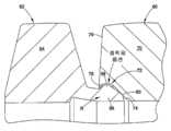
도 2a 및 도 2b는 전방 페룰 및 후방 페룰을 더 상세히 도시하고 있다. 이 예에서, 연장부(40)는 후방 페룰의 전방부(28) 및 특히 크라운(36)이 수용되는 홈 또는 포켓(42)을 제공한다. 연장부(40)는 바람직하게는 크라운(36)을 지나 압박되어 포켓(42)으로부터 후방 페룰(30)이 떨어지는 것을 방지하도록 기능하는 립(44; lip)을 포함한다. 이는 립(44)의 내경이 바람직하게는 후방 페룰의 보유된 부분, 이 예에서 크라운(36)의 최대 외부 반경 치수보다 다소 작을 수 있기 때문에 성취된다. 포켓(42)의 형상은 포켓 내로 스냅 연결되는 (상이한 형상 및 기하학적 형상을 갖는 후방 페룰에 대해) 후방 페룰의 전방부를 수용하기 위해 임의의 형태를 취할 수 있다. 립(44)은 크라운(36)의 반경방향 내향 대항 윤곽면(47)에 결합하는 반경방향 내향 대항 윤곽면(45)을 제공하여, 립(44)이 후방 페룰 내향면(47)에 대해 축방향 바이어스 또는 하중(L)(도 2b에 화살표에 의해 지시되어 있음)을 인가하는 데 사용될 수 있게 되고, 이 하중은 전방 페룰의 캠밍면(26)에 대해 접촉면(30a)에 힘을 가하거나 유지할 수 있다. 본 출원인은 표면 윤곽의 방향의 축방향 구성 요소가 일반적으로 풀 업 중에 페룰 축방향 이동의 방향에 대향하는 것을 명료화하기 위해 편의상 용어 "대항 윤곽"을 사용한다. 통상적으로, 윤곽은 절두 원추형 표면으로서 실현될 수 있지만, 다른 프로파일 또는 윤곽이 필요에 따라 사용될 수 있다. 따라서, 후방 페룰 반경방향 내향 대항 윤곽면(47)은 보유 구조체(R)와 협동한다. 연장부(40)의 가요성은, 접촉면(30a)과 캠밍면(26) 사이에 원하는 힘을 작용시킬 뿐만 아니라 접속된 페룰에 원하는 정도의 강인성을 작용시키도록 선택될 수 있다. 스냅 연결형 끼워맞춤이 다수의 경우에 바람직할 수 있지만, 이러한 것은 필수적인 것은 아니다. 몇몇 경우에, 전방 페룰의 후방부와 후방 페룰의 전방부 사이에 꼭 맞는 또는 기밀한 간섭 끼워맞춤을 갖는 것이면 충분할 수 있다. 후방 페룰의 전방부는 풀 업 중에 도관에 대해 반경방향 내향으로 압축되기 때문에, 연장부(40)는 피팅(10)의 정상 작동 및 성능에 간섭하지 않을 수 있다.2A and 2B show the front and rear ferrules in more detail. In this example, the
가요성 연장부(40)는, 몇몇 경우에 멈춤쇠 장치와 유사한, 저에너지 보유 위치로 전이하는 고에너지 간섭 끼워맞춤 또는 가압 끼워맞춤 위치로서 대안적으로 설명될 수 있는 접속을 용이하게 한다. 개별 페룰이 초기에 축방향으로 함께 압박될 때(화살표 M으로 지시되어 있는 바와 같음), 더 큰 반경 크라운(36)은 립(44)이 크라운 위에 미끄러질 수 있도록 반경방향 외향으로 연장부(40)가 펼쳐지도록 하는 경향이 있을 수 있다. 크라운(36)과 립(44) 사이의 직경의 간섭은 립(44)을 지나 포켓(42) 내로 크라운(36)을 압박하기 위해 결정 가능한 힘의 양 또는 더 높은 에너지의 사용을 초래한다. 크라운(36)이 립(44)을 일소할 때, 립(44) 및 더 일반적으로 연장부(40)는 이어서 반경방향으로 압박되지 않는 그 저에너지 위치로 복귀할 수 있다. 립(44)은 이제 크라운의 내향면(47) 후방에서 이와 접촉하기 때문에, 립(44)은 서로에 대해 축방향 압축으로 페룰을 함께 유지할 수 있다. 포켓(42)의 크기 및 반경방향 치수는 이와 같이 요구에 따라 저에너지 위치에서 크라운(36)에 대해 원하는 후프 하중을 인가하도록 선택될 수 있다. 그러나, 저에너지 상태에서, SBD를 유지하기 위해 후방 페룰의 전방 위치에 대해 상당한 반경방향 하중이 존재하지 않을 수도 있다는 것이 고려된다. 이는 후방 페룰이 달리 반경방향으로 압축되고 가능하게는 SBD에 악영향을 미치게 되는 통상의 가압 끼워맞춤 장치와 명백하게 대조된다. 가요성 연장부(40)는 후방 페룰이 전방 페룰 내에 스냅 연결됨에 따라 카트리지의 조립 중에 후방 페룰 상에 순간적인 반경방향 하중을 허용한다. 연장부(40)는, 연장부가 2개의 페룰 사이의 축방향 접촉을 제공하기 때문에 서로에 대해 페룰의 제어된 축방향 위치를 성취하는 데 사용될 수 있다는 점이 더 주목될 수 있다. 재차, 통상의 가압 끼워맞춤 조립에서, 후방 페룰이 반경방향 가압 끼워맞춤 간섭을 통해 압박됨에 따라 적절한 축방향 접촉이 존재하여, 특히 SBD를 제어하는 것을 더 어렵게 하는 것이 보장되면 고정이 요구될 수 있다.The
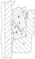
도 1a 및 도 1b의 피팅(10)이 도 3의 풀 업 위치에서 도시되어 있다. 크라운(36)의 반경방향 내향 압축(화살표 N으로 도시되어 있음)은 후방 페룰의 접촉면(30a)과 전방 페룰의 캠밍면(26) 사이의 미끄럼 접촉의 결과로서 발생한다는 것을 주목하라. 이러한 움직임은 크라운(36)이 더 이상 연장부(40)에 결합하지 않도록 크라운(36)의 외경의 감소를 초래한다. 이는 너트 및 본체가 함께 조여짐에 따라 연장부(40)가 페룰의 풀 업 및 작동에 임의의 방식으로 영향을 미치지 않는 것을 보장한다. 페룰은 예를 들어 언급된 상기 특허에 설명된 바와 동일한 방식으로 이동하고, 파지하고, 밀봉한다. 풀 업 중에 후방 페룰(30)은 화살표 P로 도시되어 있는 바와 같이 전방 페룰의 후방 단부를 반경방향으로 팽창시키는 경향이 있다는 것이 또한 주목된다. 이러한 움직임은 또한 풀 업 중에 보유 구조체 또는 연장부(40)로부터 페룰을 분리하는 것을 보장하는 데 사용될 수 있다. 풀 업 중에, 페룰(24) 및 페룰(30)은 도관(18) 상에 원하는 도관 파지부 및 피팅 조립체(10)의 밀봉부를 형성하도록 함께 축방향으로 구동된다. 크라운(36)이 더 이상 연장부(40)에 결합하지 않는 축방향 위치는 립(44)의 직경 및 크라운(36)의 직경뿐만 아니라 얼마나 신속하게 후방 페룰의 전방부가 축방향 변위에 대해 반경방향 내향으로 구동되는지를 결정할 수 있는 다양한 접촉각과 같은 다양한 기하학적 고려 사항에 의존할 수 있다. 설계자는 풀 업 중에 바람직한 축방향 위치에서 분리가 발생하게 보유 구조체(R)를 설계하도록 선택할 수 있다. 예를 들어, 설계자는 부분적인 풀 업 후에도 또는 페룰이 먼저 서로를 향해 축방향으로 이동되기 시작할 때 거의 즉시 보유 구조체로부터 분리되거나 해제되는 것을 선호할 수도 있다. 어느 경우든, 바람직한 기술은 보유 구조체(R)가 페룰 또는 너트 및 본체 피팅 구성 요소의 정상적인 풀 업 작동과 간섭하지 않는 것이다.The fitting 10 of FIGS. 1A and 1B is shown in the pull up position of FIG. 3. Note that radial inward compression of the crown 36 (shown by arrow N) occurs as a result of the sliding contact between the
본 예에서 보유 구조체(R)는 페룰을 함께 유지하기 위해 크라운(36)을 적절하게 사용하지만, 후방 페룰의 다른 기하학적 형상, 특히 적절한 보유 구조체를 사용하여 전방 페룰과 후방 페룰을 포획하거나 보유하는 데 사용될 수 있는 몇몇 다른 구조체 또는 돌기를 포함하는 후방 페룰이 대안적으로 사용될 수 있다. 크라운은 후방 페룰의 원주방향 특징부이지만, 이러한 대안적인 실시예에서, 구조체 또는 돌기는 완전히 원주방향일 필요가 없다.The retaining structure R in this example suitably uses the
도 1a 및 도 1b의 실시예는 고에너지에서 저에너지로의 전이 및 선택적으로 스냅 끼워맞춤 연결을 제공하기 위해 일체로 형성될 수 있는 연장부(40)를 도시하고 있지만, 대안적으로 연장부(40)는 포켓(42) 내에 후방 페룰의 크라운을 용이하게 수용하기에 충분한 직경으로 초기에 형성될 수 있고, 다음에 연장부(40)는 연장부에 의해 후방 페룰(30)이 유지되는 위치로 연장부(40)를 반경방향으로 압축하기 위해 몇몇 예로 제시되는 롤링(rolling), 피닝(peening) 또는 스웨이징과 같은 추가의 가공 단계를 경험할 수 있다.1A and 1B show an
도 4a 및 도 4b는 도관 그리고 너트 및 본체로의 설치에 앞서 단일 유닛, 카트리지 또는 서브조립체(25')를 형성하기 위해 조립된 상태에서 전방 페룰(60)과 후방 페룰(62) 사이의 접속부의 확대도를 도시하고 있는 다른 실시예를 도시하고 있다. 이 실시예에서, 후방 페룰(62)은 도 1a의 실시예의 후방 페룰에 비해 실질적으로 더 큰 후방 플랜지부(64)를 가져, 크라운(66)이 후방 플랜지부(64)에 축방향으로 더 근접하게 된다. 따라서, 도 1a의 실시예와 같은 전방 플랜지의 축방향 연장부에 의해 형성된 포켓 내에 끼워지기 위한 큰 전방부(68)가 존재하지 않는다. 다음으로, 이 경우에, 전방 페룰(60)의 후방 단부(70)는 예를 들어 전방 페룰의 후방벽(76)과 캠밍면(74) 사이에 축방향으로 카운터보어(counterbore)를 갖는 그 내부에 형성된 포켓 또는 리세스(72)를 갖는다. 포켓(72)은 부분적으로 페룰이 함께 가압될 때 스냅 연결하거나 또는 다른 방식으로 크라운(66)을 지나 또는 크라운(66) 위로 미끄러지는 반경방향 내향 립(78)에 의해 형성된다. 립(78)의 내경은 크라운(66)의 최외경보다 작아, 페룰이 함께 조립된 후에 립(78)이 후방 페룰 및 특히 크라운(66)이 포켓(72)으로부터 용이하게 후퇴되는 것을 방지하기 때문에 이들이 함께 유지되게 된다. 이 실시예에서, 립(78)은 반드시 더 많은 반경방향 "탄력성" 또는 팽창을 나타낼 필요는 없으며, 이에 따라 페룰을 함께 압박하기 위해 후방 페룰의 전방부는 크라운(66)이 포켓(72) 내에 위치 설정될 수 있도록 순간적으로 반경방향으로 압축되거나 만곡될 수 있게 된다. 후방 페룰의 이 순간적인 압축 동작은, 후방 페룰에 대해 요구되는 반경방향 하중이 거의 없거나 전혀 없는 저에너지 상태로 조립체가 신속하게 진행하기 때문에 SBD에 악영향을 미치지 않는다. 도 1a의 실시예에서와 같이, 립(78) 및 포켓(72)은 부분들이 단일 유닛 또는 서브조립체로서 함께 적절하게 조립될 때 스냅 또는 클릭을 제공하도록 치수 설정되고 형성될 수 있다. 또한, 립(78)은 풀 업 중에 및 풀 업 후에 피팅의 정상적인 작동 및 성능에 간섭하지 않을 것이다.4A and 4B show the connection between the
카트리지(25')는 이 예에서 립(78)이 제어된 축방향 위치에 대해 전방 페룰 캠밍면(74)에 대해 후방 페룰 접촉면(80)을 축방향으로 유지하는 유형 2 접속부일 수 있다. 대안으로, 포켓(72)의 치수는 후방 페룰(62)의 전방부(68) 및 크라운(66)이 포켓(72) 내에 더 느슨하게 보유되도록 다소 확장될 수 있다. 이는 유형 3 접속부의 버전일 수 있다. 어떠한 것이 유형 2 접속부 또는 유형 3 접속부로서 사용되더라도, 설계자는 접속부에 원하는 강인성을 제공하기 위해 보유 구조체를 위한 적절한 치수를 지정할 수 있다.The
또 다른 대안적인 실시예로서, 립(78) 대신에, 접착제가 전방 페룰에 후방 페룰 전방부(68)를 부착하는 데 사용될 수 있다. 접착제의 도포를 위한 일반적인 위치는 도 4b에 도시되어 있다. 이러한 대안적인 실시예에서, 후방 페룰의 접촉면(80)과 전방 페룰의 캠밍면(74) 사이의 직접적인 금속간 접촉을 허용할 수 있는 영역에 접착제를 도포하는 것이 바람직하다. 따라서, 이 직접적인 접촉은 접착제가 캠밍면 상에 있거나 캠밍면 상에서 유동하면 접착제에 의해 다른 방식으로 제공될 수 있는 사공간을 회피할 수 있다. 접착제를 위한 위치의 예는 포켓의 전방 페룰면과 크라운의 상부 사이의 공간을 채우기 위한 크라운(66)의 상부일 수 있다. 이러한 경우에, 접착제는 함께 연결된 페룰면과 함께 보유 구조체(R)를 포함한다. 풀 업 시에, 접착제는 전단될 수 있고, 페룰은 분리되어 2개의 개별 페룰로서 기능할 수 있다. 또 다른 대안적인 실시예에서, 후방 페룰 전방부의 기하학적 형상에 따라 전방 페룰에 리세스 형성된 포켓(72)을 제공할 필요 없이 직접적인 금속간 접촉과 함께 접착제가 페룰을 유지할 수 있게 할 수 있다.As another alternative embodiment, instead of the
도 5는 풀 업 위치에서 페룰 카트리지(25')를 포함하는 피팅을 도시하고 있다. 도 1a 및 도 1b의 실시예에서와 같이, 풀 업 시에 후방 페룰의 전방부(68)는 립(78) 및 소켓(72)과의 임의의 간섭 또는 결합으로부터 크라운(66)을 해제하기 위해 반경방향 내향으로 압축된다. 전방 페룰(60)은 또한 보유 구조체(R)로부터 크라운(68)을 더 분리하기 위해 반경방향 외향으로 회전할 수 있다.5 shows a fitting that includes a
도 6a 및 도 6b를 참조하면, 본 출원인은 페룰 카트리지 접속부의 다른 실시예를 도시하고 있다. 언급된 바와 같이, 후방 페룰(30, 62)은 상기 실시예에서 크라운(36, 66)을 포함하지만, 다수의 후방 페룰 디자인은 이러한 크라운 또는 다른 반경방향 외향 돌기를 사용하지 않는다. 다수의 경우에, 후방 페룰은 원통형 또는 테이퍼진 외부벽을 포함한다. 이러한 경우에, 페룰을 함께 보유하는 데 연장부가 사용될 수 있다.6A and 6B, the applicant shows another embodiment of a ferrule cartridge connection. As mentioned, the
다음에 도 6a 및 도 6b의 실시예에서, 불연속 페룰 카트리지(100)가 너트(14) 및 본체(12) 피팅 구성 요소를 갖는 피팅 조립체(102)와 함께 사용되는 것이 도시되어 있다. 보유 구조체(R)는 후방 페룰(106)과 전방 페룰(104)을 접속하도록 제공될 수 있다. 페룰(102)은 상기 피팅(10)의 설명과 유사한 방식으로 작동할 수 있다. 그러나, 이 경우에, 후방 페룰(106)은 크라운을 갖지 않고, 오히려 후방 페룰의 전방부(110)의 부분으로서 원통형 또는 테이퍼진 외부벽(108)을 갖는다. 이러한 경우에, 보유 구조체(R)는 전방 페룰의 후방벽(114)으로부터 축방향으로 지향된 가요성 연장부(112)의 형태로 실현될 수 있다. 연장부(112)는 전술한 바와 동일한 개념으로 가요성일 수 있고, 또한 페룰을 함께 보유하기 위해 후방 페룰의 외부벽면(108)에 마찰식으로 접촉할 수 있는 결합면(116)(도 7)을 또한 포함할 수 있다. 결합면(116)은 원통형일 수 있고 또는 후방 페룰(106)의 외부벽에 대한 파지를 용이하게 하기 위해 다른 프로파일을 가질 수 있다. 몇몇 경우에, 결합면(116)은 마찰 접촉을 증가시키기 위해, 예를 들어 조면화(roughening)에 의해, 처리될 수 있다. 도 1a 및 도 1b의 실시예에서와 같이, 도 7에서와 같은 풀 업 시에, 보유 구조체(R)는 예를 들어 후방 페룰의 전방부(110)의 반경방향 내향 압축 및/또는 전방 페룰의 후방부의 반경방향 외향 이동에 기인하여 페룰을 해제한다. 이는 TFF 특징을 허용하고, 특히 페룰은 너트 및 본체와 조합하여 2개의 페룰 시스템으로서 작동할 수 있다. 도 6b의 실시예는 카트리지(100)의 초기 조립 시 이외에 제어된 축방향 위치를 제공하지 않지만, 가요성 연장부(112)의 사용은 후방 페룰이 전방 페룰 내로 완전히 삽입될 수 있게 하여 후방 페룰의 접촉면(118)이 전방 페룰의 캠밍면(120)에 접촉하게 된다. 이 실시예는 반경방향 압축 유형 1 접속부이고, 따라서 카트리지(100)의 초기 조립 시에 RRC 및 SBD 및 또한 ABA 및 FTC를 성취하는 데 사용될 수 있다.Next, in the embodiment of FIGS. 6A and 6B, a
도 8a, 도 8b 및 도 9의 유형 2 실시예는 도 6a, 도 6b 및 도 7의 실시예와 유사하고, 유사한 도면 부호가 유사한 부분 또는 특징을 나타내므로 상세한 설명의 반복은 필요하지 않다. 2개의 실시예는 원주방향 노치 또는 리세스(124)가 후방 페룰의 전방부(126) 내에 형성되는 후방 페룰(122)을 페룰 카트리지(120)가 포함할 수 있다는 점에서 구조적으로 상이하다. 이 리세스(24)는 후방 페룰의 외부벽(122a)에 형성될 수 있는데, 이 외부벽은 요구에 따라 원통형이거나, 테이퍼지거나 또는 다른 프로파일을 가질 수 있다. 이 리세스(124)는 전방 페룰(130)의 가요성 연장부(112)의 반경방향 내향 돌출부(128)를 수용한다. 반경방향 내향 돌출부(128)는 전방 페룰의 캠밍면(138)에 대해 후방 페룰의 접촉면(136)에 대한 축방향 하중을 인가하는 후방 페룰에 축방향 바이어스를 적용하기 위해 리세스(124)의 표면 또는 코너(134)에 결합하는 대항 윤곽면(132)을 제시할 수 있다. 따라서, 이 실시예는 이와 같이 요구에 따라 제어된 축방향 위치형 접속부를 제공하는 데 사용될 수 있다. 대안으로, 리세스(124) 및 반경방향 내향 돌출부(128)는 페룰(130, 122)이 유형 3 접속부를 제공하기 위해 함께 느슨하게 유지될 수 있게 하기 위해 치수 설정될 수 있다. 페룰이 불연속 카트리지(120)로서 함께 접속될 때 후방 페룰의 반경방향 치수 및 형상을 수용하도록 요구에 따라 릴리프 노치 또는 리세스(140)가 제공될 수 있다는 것을 주목하라. 도 9는 풀 업 위치에서 도 8a의 실시예를 도시하고 있고, 전술된 다른 실시예에서와 같이, 보유 구조체(R)가 풀 업 중에 페룰로부터 해제되고, 풀 업 중에 페룰 및 피팅 구성 요소와 간섭하지 않는다.Type 2 embodiments of FIGS. 8A, 8B, and 9 are similar to the embodiments of FIGS. 6A, 6B, and 7, and like reference numerals represent similar parts or features, and no repetition of the detailed description is required. The two embodiments are structurally different in that the
도 10을 참조하여, 본 출원인은 상기 도 1a 및 도 1b의 실시예의 수정예인 유형 3 접속부의 다른 실시예를 설명한다. 재차, 유사한 부분 및 특징에는 동일한 도면 부호가 제공된다. 이 실시예에서, 포켓(42)은 크라운(36)을 더 느슨하게 보유하기 위해 확장될 수 있고, 이는 2개의 페룰 사이의 더 느슨하지만 여전히 적당히 강인한 접속부를 허용할 수 있다. 가요성 연장부(40)가 또한 이와 같이 요구에 따라 강인성을 증가시키기 위해 도 1b의 버전에 비해 전방 페룰의 후방벽(41)으로부터 큰 정도로 반경방향 내향으로 연장될 수 있다. 가요성 연장부(40)는 또한 더 느슨한 끼워맞춤의 견지에서 함께 더 강인하고 확실한 페룰의 보유를 제공하기 위한 반경방향 돌기(44')를 포함할 수 있다.With reference to FIG. 10, the applicant describes another embodiment of a type 3 connection that is a modification of the embodiment of FIGS. 1A and 1B above. Again, like parts and features are provided with the same reference numerals. In this embodiment, the
본 발명의 양태가 예시적인 실시예를 참조하여 설명되었다. 본 명세서의 숙독 및 이해 시에 다른 수정 및 변경에 대해 수정 및 변경이 행해질 수 있다. 이들이 첨부된 청구범위 또는 이들의 등가물의 범주 내에 있는 한 본 발명은 이러한 모든 수정 및 변경을 포함하는 것으로 의도된다.Aspects of the invention have been described with reference to exemplary embodiments. Modifications and changes may be made to other modifications and changes in its reading and understanding herein. It is intended that the present invention cover all such modifications and variations as long as they fall within the scope of the appended claims or their equivalents.
10: 피팅12: 제1 피팅 구성 요소
14: 제2 피팅 구성 요소16: 나사산 형성 접속부
18: 도관26: 캠밍면
28: 전방부30: 페룰
32: 피동면34: 구동면
36: 크라운40: 연장부
42: 포켓44: 립10: fitting 12: first fitting component
14: second fitting component 16: threaded connection
18: conduit 26: camming surface
28: front part 30: ferrule
32: driven surface 34: driving surface
36: crown 40: extension
42: pocket 44: rib
Claims (44)
Translated fromKorean제1 도관 파지 장치 및 제2 도관 파지 장치로서, 상기 제1 도관 파지 장치는 그 후방부에 캠밍면(camming surface)을 포함하고, 상기 제2 도관 파지 장치는 상기 캠밍면에 접촉하는 접촉면을 그 전방부에 포함하는 것인 제1 도관 파지 장치 및 제2 도관 파지 장치와,
상기 제1 도관 파지 장치의 일부이며 상기 제1 도관 파지 장치의 후방부와 일체로 형성되는 제1 부분 및 제2 도관 파지 장치의 일부이며 상기 제2 도관 파지 장치의 전방부와 일체로 형성되는 제2 부분을 포함하는 보유 구조체로서, 상기 제1 부분은 상기 제2 도관 파지 장치의 외경보다 작은 내경을 가짐으로써, 상기 보유 구조체가 제1 도관 파지 장치 및 제2 도관 파지 장치를 서로에 대한 느슨한 보유 상태에서 함께 유지하여, 상기 제1 도관 파지 장치 및 상기 제2 도관 파지 장치의 서로에 대한 회전의 자유를 허용하는 것인 보유 구조체
를 포함하는 서브조립체.In the subassembly for conduit fittings,
A first conduit gripping device and a second conduit gripping device, wherein the first conduit gripping device has a camming surface at its rear portion, and the second conduit gripping device has a contact surface in contact with the camming surface. A first conduit gripping device and a second conduit gripping device, including at the front;
A first portion that is part of the first conduit gripping apparatus and is integrally formed with a rear portion of the first conduit gripping apparatus and is part of a second conduit gripping apparatus that is integrally formed with the front portion of the second conduit gripping apparatus A retaining structure comprising two portions, wherein the first portion has an inner diameter less than an outer diameter of the second conduit gripping device such that the retaining structure loosely holds the first conduit gripping device and the second conduit gripping device relative to each other. Holding together in a state to allow freedom of rotation of the first conduit gripping device and the second conduit gripping device relative to each other.
Subassembly comprising a.
제1 도관 파지 장치 및 제2 도관 파지 장치로서, 상기 제1 도관 파지 장치는 그 후방부에 캠밍면(camming surface)을 포함하고, 상기 제2 도관 파지 장치는 상기 캠밍면에 접촉하는 접촉면을 그 전방부에 포함하는 것인 제1 도관 파지 장치 및 제2 도관 파지 장치와,
상기 제1 도관 파지 장치의 일부이며 상기 제1 도관 파지 장치의 후방부와 일체로 형성되는 제1 부분 및 제2 도관 파지 장치의 일부이며 상기 제2 도관 파지 장치의 전방부와 일체로 형성되는 제2 부분을 포함하는 보유 구조체로서, 상기 제1 부분은 상기 제2 도관 파지 장치의 외경보다 작은 내경을 가짐으로써, 상기 보유 구조체는 상기 제1 도관 파지 장치 및 상기 제2 도관 파지 장치를 불연속적 조립체로서 함께 유지하는 것인 보유 구조체를 포함하고,
상기 제1 도관 파지 장치 및 상기 제2 도관 파지 장치는 도관의 외부면에 대해 반경 방향으로 압축될 때 각각 도관 파지 및 도관 유체 기밀 밀봉을 제공하는 것인 서브조립체.In the subassembly for conduit fittings,
A first conduit gripping device and a second conduit gripping device, wherein the first conduit gripping device has a camming surface at its rear portion, and the second conduit gripping device has a contact surface in contact with the camming surface. A first conduit gripping device and a second conduit gripping device, including at the front;
A first portion that is part of the first conduit gripping apparatus and is integrally formed with a rear portion of the first conduit gripping apparatus and is part of a second conduit gripping apparatus that is integrally formed with the front portion of the second conduit gripping apparatus A retaining structure comprising two portions, wherein the first portion has an inner diameter less than an outer diameter of the second conduit gripping device such that the retaining structure discontinuously comprises the first conduit gripping device and the second conduit gripping device. And a retention structure to hold together as
Wherein the first conduit gripping device and the second conduit gripping device each provide conduit gripping and conduit fluid tight sealing when radially compressed relative to an outer surface of the conduit.
제1 도관 파지 장치 및 제2 도관 파지 장치로서, 상기 제1 도관 파지 장치는 그 후방부에 캠밍면(camming surface)을 포함하고, 상기 제2 도관 파지 장치는 상기 캠밍면에 접촉하는 접촉면을 그 전방부에 포함하는 것인 제1 도관 파지 장치 및 제2 도관 파지 장치;
상기 제1 도관 파지 장치의 일부이며 상기 제1 도관 파지 장치의 후방부와 일체로 형성되는 제1 부분 및 제2 도관 파지 장치의 일부이며 상기 제2 도관 파지 장치의 전방부와 일체로 형성되는 제2 부분을 포함하는 보유 구조체로서, 상기 제1 부분은 상기 제2 도관 파지 장치의 외경보다 작은 내경을 가짐으로써, 상기 보유 구조체는 상기 제1 도관 파지 장치 및 상기 제2 도관 파지 장치를 불연속적 조립체로서 함께 유지하는 것인 보유 구조체; 및
제1 피팅 구성 요소 및 제1 피팅 구성 요소에 연결될 수 있는 제2 피팅 구성 요소로서, 상기 서브조립체는 상기 제1 피팅 구성 요소 및 상기 제2 피팅 구성 요소 사이에 배치되고, 상기 제1 도관 파지 장치 및 상기 제2 도관 파지 장치는 상기 제1 피팅 구성 요소의 상기 제2 피팅 구성 요소와의 풀 업 중에 분리됨으로써, 상기 보유 구조체가 상기 제1 도관 파지 장치 및 상기 제2 도관 파지 장치를 더이상 함께 유지하지 않는 것인, 제1 피팅 구성 요소 및 제2 피팅 구성 요소를 포함하는 서브조립체.In the subassembly for conduit fittings,
A first conduit gripping device and a second conduit gripping device, wherein the first conduit gripping device has a camming surface at its rear portion, and the second conduit gripping device has a contact surface in contact with the camming surface. A first conduit gripping device and a second conduit gripping device including in the front portion;
A first portion that is part of the first conduit gripping apparatus and is integrally formed with a rear portion of the first conduit gripping apparatus and is part of a second conduit gripping apparatus that is integrally formed with the front portion of the second conduit gripping apparatus A retaining structure comprising two portions, wherein the first portion has an inner diameter less than an outer diameter of the second conduit gripping device such that the retaining structure discontinuously comprises the first conduit gripping device and the second conduit gripping device. Retention structure as retained together; And
A first fitting component and a second fitting component that may be connected to the first fitting component, wherein the subassembly is disposed between the first fitting component and the second fitting component, and the first conduit gripping apparatus And the second conduit gripping device is separated during pull-up of the first fitting component with the second fitting component such that the retaining structure no longer holds the first conduit gripping device and the second conduit gripping device together. Wherein the subassembly comprises a first fitting component and a second fitting component.
Applications Claiming Priority (3)
| Application Number | Priority Date | Filing Date | Title |
|---|---|---|---|
| US12129808P | 2008-12-10 | 2008-12-10 | |
| US61/121,298 | 2008-12-10 | ||
| PCT/US2009/067508WO2010068762A1 (en) | 2008-12-10 | 2009-12-10 | Ferrule assembly for conduit fitting |
Related Parent Applications (1)
| Application Number | Title | Priority Date | Filing Date |
|---|---|---|---|
| KR1020177009809ADivisionKR101864094B1 (en) | 2008-12-10 | 2009-12-10 | Ferrule assembly for conduit fitting |
Publications (2)
| Publication Number | Publication Date |
|---|---|
| KR20180059572A KR20180059572A (en) | 2018-06-04 |
| KR102048647B1true KR102048647B1 (en) | 2019-11-25 |
Family
ID=41683498
Family Applications (4)
| Application Number | Title | Priority Date | Filing Date |
|---|---|---|---|
| KR1020167016306AExpired - Fee RelatedKR101729457B1 (en) | 2008-12-10 | 2009-12-10 | Ferrule assembly for conduit fitting |
| KR1020177009809AExpired - Fee RelatedKR101864094B1 (en) | 2008-12-10 | 2009-12-10 | Ferrule assembly for conduit fitting |
| KR1020187014606AExpired - Fee RelatedKR102048647B1 (en) | 2008-12-10 | 2009-12-10 | Ferrule assembly for conduit fitting |
| KR1020117015902AExpired - Fee RelatedKR101633947B1 (en) | 2008-12-10 | 2009-12-10 | Ferrule assembly for conduit fitting |
Family Applications Before (2)
| Application Number | Title | Priority Date | Filing Date |
|---|---|---|---|
| KR1020167016306AExpired - Fee RelatedKR101729457B1 (en) | 2008-12-10 | 2009-12-10 | Ferrule assembly for conduit fitting |
| KR1020177009809AExpired - Fee RelatedKR101864094B1 (en) | 2008-12-10 | 2009-12-10 | Ferrule assembly for conduit fitting |
Family Applications After (1)
| Application Number | Title | Priority Date | Filing Date |
|---|---|---|---|
| KR1020117015902AExpired - Fee RelatedKR101633947B1 (en) | 2008-12-10 | 2009-12-10 | Ferrule assembly for conduit fitting |
Country Status (9)
| Country | Link |
|---|---|
| US (3) | US9267627B2 (en) |
| EP (2) | EP2370723B1 (en) |
| JP (5) | JP5984393B2 (en) |
| KR (4) | KR101729457B1 (en) |
| CN (4) | CN105333246B (en) |
| CA (1) | CA2750889C (en) |
| IL (4) | IL213361A0 (en) |
| RU (3) | RU2507433C9 (en) |
| WO (1) | WO2010068762A1 (en) |
Families Citing this family (35)
| Publication number | Priority date | Publication date | Assignee | Title |
|---|---|---|---|---|
| US8740261B2 (en) | 2008-06-02 | 2014-06-03 | Optimize Technologies, Inc. | Fitting assembly |
| US8201854B2 (en)* | 2008-06-02 | 2012-06-19 | Optimize Technologies, Inc. | Hybrid ferrule |
| KR101729457B1 (en) | 2008-12-10 | 2017-04-21 | 스와겔로크 컴패니 | Ferrule assembly for conduit fitting |
| JP5948251B2 (en)* | 2010-01-21 | 2016-07-06 | スウエイジロク・カンパニー | Conduit gripping device having retention structure for conduit joint |
| JP5899766B2 (en)* | 2011-09-30 | 2016-04-06 | ダイキン工業株式会社 | Bite-type pipe connection structure |
| DE202012101631U1 (en) | 2012-05-03 | 2012-08-17 | Schwer Fittings Gmbh | Device for fixing a pipe to a connection part |
| DE102012103878A1 (en) | 2012-05-03 | 2013-11-07 | Schwer Fittings Gmbh | Device for fixing a pipe to a connection part |
| EP2870469B1 (en)* | 2012-07-05 | 2020-09-09 | Agilent Technologies, Inc. | Single-piece ferrule joint with undercut tapering part |
| USD735853S1 (en) | 2012-09-24 | 2015-08-04 | Agilent Technologies, Inc. | Ferrule |
| FR3003330B1 (en)* | 2013-03-18 | 2015-07-17 | Arkema France | PLUNGER TUBE CONNECTION DEVICE FOR A PACKAGING CONTAINER OF A PRODUCT, IN PARTICULAR A CHEMICAL |
| US20160221014A1 (en)* | 2013-09-25 | 2016-08-04 | United Technologies Corporation | Simplified cold spray nozzle and gun |
| CN104913132B (en)* | 2014-03-10 | 2019-05-10 | 科斯摩工机股份有限公司 | The derailing prevention device and pipe fitting of fluid hose |
| EP3140580B1 (en) | 2014-05-09 | 2020-03-25 | Swagelok Company | Conduit fitting with components adapted for facilitating assembly |
| WO2017035439A1 (en)* | 2015-08-26 | 2017-03-02 | Swagelok Company | Conduit retaining structure for conduit fitting |
| JP6283640B2 (en)* | 2015-09-30 | 2018-02-21 | 因幡電機産業株式会社 | Pipe fitting |
| KR101788072B1 (en) | 2015-10-01 | 2017-10-19 | 김성훈 | Tube fitting apparatus |
| US10961790B2 (en)* | 2015-11-19 | 2021-03-30 | Halliburton Energy Services, Inc. | Method and apparatus for retaining components in a downhole motor |
| WO2017136210A1 (en) | 2016-02-04 | 2017-08-10 | Swagelok Company | Component retaining structure for conduit fitting |
| US20170261137A1 (en) | 2016-03-08 | 2017-09-14 | Swagelok Company | Component retaining structure for conduit fitting |
| GB2554889B (en)* | 2016-10-12 | 2019-01-02 | Poulton Tech Limited | A seal assembly |
| US10520118B2 (en) | 2017-05-11 | 2019-12-31 | Circor International | Tube fitting assembly |
| CN107606345A (en)* | 2017-09-05 | 2018-01-19 | 煌盛集团重庆管业有限公司 | A kind of hole pattern steel strip-plastic composite pipe connector of convenient disassembly |
| WO2019143497A1 (en)* | 2018-01-19 | 2019-07-25 | Omega Flex, Inc. | Corrugated medical tubing system having fitting with anti-tamper sleeve |
| CN112166279B (en)* | 2018-04-27 | 2022-09-27 | 斯瓦戈洛克公司 | Ferrule assembly for a catheter fitting |
| CN110500455B (en)* | 2018-05-16 | 2021-11-09 | 深圳市飞托克实业有限公司 | Double-clamping sleeve connecting assembly |
| CN113518879B (en) | 2019-04-01 | 2023-12-15 | 斯瓦戈洛克公司 | Push-to-connect catheter adapter assembly and apparatus |
| KR102291871B1 (en) | 2019-10-18 | 2021-08-19 | 유학현 | Ferrule assembly for fitting |
| US12220769B2 (en)* | 2019-11-13 | 2025-02-11 | Micro Motion, Inc. | Methods for coupling and hermetically sealing components composed of different materials |
| US20210254766A1 (en) | 2020-02-13 | 2021-08-19 | Caterpillar Inc. | Seal assembly |
| US11831720B2 (en) | 2021-07-13 | 2023-11-28 | Contitech Usa, Inc. | Test results transfer protocol |
| KR20240095515A (en) | 2021-11-17 | 2024-06-25 | 스웨이지락 캄파니 | check valve |
| FR3138679B1 (en)* | 2022-08-03 | 2024-08-02 | Commissariat Energie Atomique | Tube holding device |
| WO2025061634A1 (en) | 2023-09-21 | 2025-03-27 | Danfoss A/S | Preassembled tensioning arrangement for a pipe connecting arrangement and pipe connecting arrangement comprising a preassembled tensioning arrangement |
| WO2025061632A1 (en) | 2023-09-21 | 2025-03-27 | Danfoss A/S | Tube coupling with differently tapered connection ends and method of mounting a tube coupling |
| WO2025061633A1 (en) | 2023-09-21 | 2025-03-27 | Danfoss A/S | Tube coupling with clamping effect for the tube and method of mounting a tube coupling |
Citations (1)
| Publication number | Priority date | Publication date | Assignee | Title |
|---|---|---|---|---|
| DE19607784B4 (en)* | 1995-03-29 | 2006-08-24 | Simplex Wilfer Gmbh & Co. | Compression fittings |
Family Cites Families (108)
| Publication number | Priority date | Publication date | Assignee | Title |
|---|---|---|---|---|
| US1672879A (en) | 1926-12-30 | 1928-06-12 | Harris Calorific Co | Adapter for tubular members |
| US1809064A (en) | 1929-05-10 | 1931-06-09 | Crouse Hinds Co | Threadless connecter |
| US2389233A (en) | 1942-07-28 | 1945-11-20 | Cowles Irving | Coupling nut for flanged tubing conduits |
| US2497273A (en) | 1946-08-21 | 1950-02-14 | Brockway Company | Pipe connection |
| US2547889A (en) | 1946-12-14 | 1951-04-03 | Brockway Company | Pipe connector |
| DE841091C (en) | 1950-12-02 | 1952-06-13 | Hans Kreidel Jun | Pipe connection |
| US3083989A (en) | 1957-04-30 | 1963-04-02 | Resistoflex Corp | Reusable fitting with metallic sealing ring |
| US3074747A (en) | 1958-09-08 | 1963-01-22 | Joslyn Mfg & Supply Co | Coupling nut assembly |
| US3004776A (en) | 1958-12-12 | 1961-10-17 | Sebardt Wilhelm | Pipe coupling having a sealing nut with a frangible section |
| US3218096A (en) | 1960-05-19 | 1965-11-16 | Resistoflex Corp | Fluid coupling assembly |
| US3069188A (en)* | 1961-01-26 | 1962-12-18 | Cullen B Crawford | Tube coupling |
| US3103373A (en)* | 1961-06-29 | 1963-09-10 | Crawford Fitting Co | Controlled phase sequential gripping device |
| US3215457A (en)* | 1962-04-17 | 1965-11-02 | Hoke Mfg Company Inc | Pipe coupling |
| US3250550A (en)* | 1964-02-13 | 1966-05-10 | Gilbert T Lyon | Self-flaring tube coupling |
| US3306637A (en) | 1964-09-04 | 1967-02-28 | Resistoflex Corp | Reuseable hose end fitting |
| US3219367A (en) | 1964-10-23 | 1965-11-23 | Imp Eastman Corp | Tube connector with permanently assembled sleeve and nut elements |
| US3325192A (en) | 1964-11-19 | 1967-06-13 | Parker Hannifin Corp | Flareless tube coupling nut and ferrule assembly |
| US3321947A (en)* | 1965-09-13 | 1967-05-30 | Hoke Mfg Company Inc | Pipe coupling and method of making |
| US3433508A (en)* | 1967-04-17 | 1969-03-18 | Hoke Inc | Pipe coupling |
| GB1233371A (en)* | 1967-08-26 | 1971-05-26 | ||
| GB1233372A (en)* | 1967-08-26 | 1971-05-26 | ||
| US3498647A (en) | 1967-12-01 | 1970-03-03 | Karl H Schroder | Connector for coaxial tubes or cables |
| US3707302A (en) | 1970-08-27 | 1972-12-26 | Ite Imperial Corp | High performance fitting |
| CA961888A (en)* | 1971-04-15 | 1975-01-28 | Leonard P. Spontelli | Tube fitting |
| JPS5011529U (en)* | 1973-05-29 | 1975-02-06 | ||
| US3893716A (en)* | 1974-04-01 | 1975-07-08 | Weatherhead Co | Flareless fitting |
| US3972547A (en) | 1974-11-21 | 1976-08-03 | Zenzo Ono | Locking and nonseal joint device |
| SE406008B (en)* | 1975-12-30 | 1979-01-15 | Normark Olof Magnus | FRICTION COUPLING BETWEEN TWO ELEMENTS |
| US4022497A (en) | 1976-01-09 | 1977-05-10 | Imperial-Eastman Corporation | One-piece nut and sleeve for improved tube fitting |
| US4136897A (en) | 1976-04-08 | 1979-01-30 | Parker-Hannifin Corporation | Coupling device for tubular members |
| US4022597A (en)* | 1976-04-23 | 1977-05-10 | Gulf Oil Corporation | Separation of liquid hydrocarbons from natural gas |
| JPS597045B2 (en) | 1976-08-24 | 1984-02-16 | 株式会社山科精工所 | Drill screw and mold for its production |
| DE2847596A1 (en) | 1977-05-04 | 1980-05-14 | Olov Magnus Normark | COUPLING BETWEEN MECHANICAL ELEMENTS |
| GB2032555B (en)* | 1978-10-27 | 1983-02-16 | Normark O | Means for effecting a friction coupling between inner and outer relatively axially movable members |
| FR2461186A1 (en)* | 1979-07-06 | 1981-01-30 | Legris | IMPROVEMENTS IN PIPE FITTINGS, IN PARTICULAR FOR HIGH PRESSURE FLUID PIPES |
| GB2085537B (en)* | 1980-10-09 | 1984-05-16 | Fuji Metal Mfg | Improvements in pipe couplings |
| JPS57187985A (en) | 1981-05-15 | 1982-11-18 | Nippon Telegr & Teleph Corp <Ntt> | Gain stabilizing optical amplifier |
| US4500117A (en) | 1982-11-24 | 1985-02-19 | Shell Oil Company | Pipeline connector |
| US4575274A (en) | 1983-03-02 | 1986-03-11 | Gilbert Engineering Company Inc. | Controlled torque connector assembly |
| US4592574A (en) | 1983-11-28 | 1986-06-03 | Allied Tube & Conduit Corporation | Conduit coupling assembly and method of use |
| DE3607268A1 (en) | 1986-03-05 | 1987-09-10 | Dueker Eisenwerk | SHEAR-PROOF CONNECTOR |
| US4826218A (en)* | 1987-12-10 | 1989-05-02 | Crawford Fitting Co. | Coupling device for heavy-walled tubular members |
| US5388866A (en) | 1990-03-09 | 1995-02-14 | Lourdes Industries | High pressure coupling with provision for preventing separation of parts and with anti-galling provision |
| US5074599A (en)* | 1990-10-30 | 1991-12-24 | Crawford Fitting Co. | Tube fitting |
| SU1809230A1 (en)* | 1990-11-26 | 1993-04-15 | Volzh N Proizv Ob Edineniya En | Pipeline joint |
| DE4038539C1 (en) | 1990-12-03 | 1992-04-30 | Parker-Ermeto Gmbh, 4800 Bielefeld, De | |
| DE4219722C2 (en) | 1992-06-17 | 1996-02-29 | Klaus Lehmann | Connection system for pipes |
| JP3077817B2 (en)* | 1993-07-20 | 2000-08-21 | フイルマツク ピーテイワイ リミテツド | Joint for outer surface engagement of resin pipe |
| US5568910A (en)* | 1995-03-02 | 1996-10-29 | Delmarva Laboratories, Inc. | Anesthesia machine |
| US5586910A (en) | 1995-08-11 | 1996-12-24 | Amphenol Corporation | Clamp nut retaining feature |
| US5961160A (en) | 1995-08-16 | 1999-10-05 | Froehlich; Manfred | High-pressure connection system |
| US6079749C1 (en) | 1996-08-08 | 2001-11-06 | Omega Flex Inc | Preassembled fitting for use with corrugated tubing |
| DE19709464C2 (en)* | 1997-03-07 | 2000-03-09 | Voss Armaturen | Pipe fitting with cutting ring for metallic pipes |
| US5882050A (en) | 1997-04-15 | 1999-03-16 | Williams; Peter C. | Ferrule with relief to reduce galling |
| EP1503129B1 (en)* | 1997-04-15 | 2011-06-08 | Swagelok Company | Ferrule with relief to reduce galling |
| JPH10288287A (en)* | 1997-04-15 | 1998-10-27 | Mitsubishi Heavy Ind Ltd | Pipe joint |
| US6629708B2 (en) | 1997-04-15 | 2003-10-07 | Swagelok Company | Ferrule with relief to reduce galling |
| TW473600B (en)* | 1997-04-15 | 2002-01-21 | Swagelok Co | Tube fitting, rear ferrule for a two ferrule tube fitting and ferrule for a tube fitting and a non-flared tube fitting |
| JPH1130368A (en) | 1997-07-14 | 1999-02-02 | Chiyoda Kucho Kiki Kk | Piping joint |
| US6079949A (en)* | 1998-11-13 | 2000-06-27 | Lasko Holdings, Inc. | Ratchet assembly for pedestal fan |
| US6640457B2 (en) | 1999-09-13 | 2003-11-04 | Swagelok Company | Intrinsic gauging for tube fittings |
| US7194817B2 (en) | 1999-09-13 | 2007-03-27 | Swagelok Company | Intrinsic gauging for tube fittings |
| CN2409405Y (en)* | 2000-03-13 | 2000-12-06 | 陈亦武 | Quick connecting joint |
| ES2238557T3 (en) | 2001-02-06 | 2005-09-01 | Swagelok Company | TUBE COUPLING WITH A SEPARABLE TUBE FIXING RING. |
| US6851729B2 (en)* | 2001-12-07 | 2005-02-08 | Parker-Hannifin Corporation | Tube fitting for medium pressure applications |
| JP2003232474A (en) | 2002-02-08 | 2003-08-22 | Nasco Fitting Kk | Pipe joint |
| JP2003287177A (en)* | 2002-03-28 | 2003-10-10 | Tokai Rubber Ind Ltd | Hose connecting metal fitting |
| US6905142B2 (en) | 2002-09-25 | 2005-06-14 | Huck Patents, Inc. | Hydraulic coupling |
| JP4895069B2 (en)* | 2004-03-29 | 2012-03-14 | イハラサイエンス株式会社 | Pipe fitting |
| TW200602577A (en) | 2004-04-22 | 2006-01-16 | Swagelok Co | Fitting for tube and pipe |
| CN100554748C (en)* | 2004-04-22 | 2009-10-28 | 斯瓦戈洛克公司 | Fitting for pipes and tubes and method of assembling the fitting |
| US7497483B2 (en) | 2004-04-22 | 2009-03-03 | Swagelok Company | Fitting for tube and pipe with cartridge |
| JP3939311B2 (en)* | 2004-05-25 | 2007-07-04 | ナスコフィッティング株式会社 | Pipe fitting |
| CA2469353A1 (en) | 2004-05-31 | 2005-11-30 | Masco Canada Limited | Pipe coupling |
| US7055868B2 (en) | 2004-07-09 | 2006-06-06 | Highlands Corporation | Corrugated tube fitting |
| US20060138772A1 (en) | 2004-12-27 | 2006-06-29 | Carrier Corporation | Braze-free connector |
| US7316777B2 (en) | 2005-01-28 | 2008-01-08 | Valco Instruments Co., Inc. | Compression fitting nut with interlocked ferrule |
| DE102005006798A1 (en)* | 2005-02-14 | 2006-08-24 | Eaton Fluid Connectors Gmbh | joint assembly |
| US20060237962A1 (en) | 2005-04-22 | 2006-10-26 | Anderson Bret M | Tool for preparing fitting and conduit connection |
| WO2007019141A1 (en) | 2005-08-04 | 2007-02-15 | Parker-Hannifin Corporation | Pre-assemblable, push-in fitting connection for corrugated tubing |
| AT501475B8 (en)* | 2005-09-15 | 2007-02-15 | E Hawle Armaturenwerke Gmbh | CONNECTING PIECE FOR THE END OF A ROUND, PARTICULARLY TUBULAR OBJECT |
| JP2007120724A (en)* | 2005-10-31 | 2007-05-17 | Tokai Rubber Ind Ltd | Connecting structure of hose fitting |
| JP2007146893A (en)* | 2005-11-24 | 2007-06-14 | Toyota Motor Corp | Piping joint structure |
| JP3901207B1 (en) | 2005-11-29 | 2007-04-04 | ダイキン工業株式会社 | Pipe fitting |
| KR20080091186A (en)* | 2006-01-13 | 2008-10-09 | 스와겔로크 컴패니 | Fitting for tube or pipe |
| JP5023721B2 (en) | 2006-01-31 | 2012-09-12 | ダイキン工業株式会社 | Bite-type pipe connection structure |
| JP4124257B2 (en)* | 2006-12-12 | 2008-07-23 | ダイキン工業株式会社 | Pipe fitting |
| JP5012118B2 (en) | 2007-03-19 | 2012-08-29 | ダイキン工業株式会社 | Bite type fittings, refrigeration equipment and hot water equipment |
| JP2008286337A (en)* | 2007-05-18 | 2008-11-27 | Daikin Ind Ltd | Bite type fittings, refrigeration equipment and hot water equipment |
| JP4045305B1 (en)* | 2007-05-24 | 2008-02-13 | 有限会社ワタリ・システムメカニック | Pipe fitting |
| CN201053546Y (en)* | 2007-06-22 | 2008-04-30 | 江苏海纳机电制造有限公司 | Ferrule type pipeline joint |
| WO2009003015A1 (en) | 2007-06-26 | 2008-12-31 | Swagelok Company | Apparatus and method of zero clearance connection with optional sensing function |
| WO2009018079A1 (en) | 2007-07-27 | 2009-02-05 | Swagelok Company | Tapered nut for tube or pipe fitting |
| JP2009058565A (en)* | 2007-08-30 | 2009-03-19 | Seiko Epson Corp | Electro-optical device manufacturing apparatus and method |
| JP4858372B2 (en)* | 2007-09-11 | 2012-01-18 | ダイキン工業株式会社 | Biting type pipe connection structure, valve, biting type pipe fitting and refrigeration system |
| JP5266956B2 (en) | 2007-09-11 | 2013-08-21 | ダイキン工業株式会社 | Dual-use pipe joint, dedicated tool for this dual-use pipe joint, refrigeration equipment, separation type air conditioner |
| JP2009085430A (en) | 2007-09-11 | 2009-04-23 | Daikin Ind Ltd | Pipe joint and refrigeration apparatus using the same |
| JP5326457B2 (en) | 2007-09-28 | 2013-10-30 | ダイキン工業株式会社 | Biting type pipe connection structure, valve, biting type pipe fitting and refrigeration system |
| KR101729457B1 (en) | 2008-12-10 | 2017-04-21 | 스와겔로크 컴패니 | Ferrule assembly for conduit fitting |
| WO2010129261A1 (en) | 2009-04-27 | 2010-11-11 | Swagelok Company | Tapered drive nut for conduit fitting |
| JP5948251B2 (en) | 2010-01-21 | 2016-07-06 | スウエイジロク・カンパニー | Conduit gripping device having retention structure for conduit joint |
| EP2409676A1 (en)* | 2010-07-06 | 2012-01-25 | Intervet International B.V. | Method for dosing a fluid formulation containing a medicinal substance |
| CN202032206U (en)* | 2011-03-21 | 2011-11-09 | 浙江快科科技有限公司 | Double-cutting sleeve type tube connector |
| JP5899766B2 (en) | 2011-09-30 | 2016-04-06 | ダイキン工業株式会社 | Bite-type pipe connection structure |
| JP2013076457A (en) | 2011-09-30 | 2013-04-25 | Daikin Industries Ltd | Tube connection structure |
| US20130106103A1 (en) | 2011-11-02 | 2013-05-02 | Tylok International, Inc. | Face seal conduit fitting |
| US8641099B2 (en) | 2012-07-05 | 2014-02-04 | United Technologies Corporation | Coupling with one-piece plural nipples |
| WO2017035439A1 (en)* | 2015-08-26 | 2017-03-02 | Swagelok Company | Conduit retaining structure for conduit fitting |
- 2009
- 2009-12-10KRKR1020167016306Apatent/KR101729457B1/ennot_activeExpired - Fee Related
- 2009-12-10CNCN201510731726.7Apatent/CN105333246B/enactiveActive
- 2009-12-10KRKR1020177009809Apatent/KR101864094B1/ennot_activeExpired - Fee Related
- 2009-12-10KRKR1020187014606Apatent/KR102048647B1/ennot_activeExpired - Fee Related
- 2009-12-10CACA2750889Apatent/CA2750889C/ennot_activeExpired - Fee Related
- 2009-12-10CNCN201510732073.4Apatent/CN105333250B/enactiveActive
- 2009-12-10EPEP09793392.3Apatent/EP2370723B1/ennot_activeNot-in-force
- 2009-12-10CNCN201510731712.5Apatent/CN105333249B/enactiveActive
- 2009-12-10USUS12/635,301patent/US9267627B2/enactiveActive
- 2009-12-10RURU2011128360/06Apatent/RU2507433C9/ennot_activeIP Right Cessation
- 2009-12-10CNCN200980156418.9Apatent/CN102308137B/enactiveActive
- 2009-12-10KRKR1020117015902Apatent/KR101633947B1/ennot_activeExpired - Fee Related
- 2009-12-10WOPCT/US2009/067508patent/WO2010068762A1/enactiveApplication Filing
- 2009-12-10EPEP16201872.5Apatent/EP3156709A1/ennot_activeWithdrawn
- 2009-12-10JPJP2011540891Apatent/JP5984393B2/ennot_activeExpired - Fee Related
- 2011
- 2011-06-05ILIL213361Apatent/IL213361A0/enactiveIP Right Grant
- 2013
- 2013-11-27RURU2013152732Apatent/RU2643890C2/ennot_activeIP Right Cessation
- 2015
- 2015-11-02JPJP2015215458Apatent/JP6058103B2/ennot_activeExpired - Fee Related
- 2015-11-18ILIL242651Apatent/IL242651A/enactiveIP Right Grant
- 2015-11-18ILIL242650Apatent/IL242650A/enactiveIP Right Grant
- 2016
- 2016-01-21USUS15/003,237patent/US10619770B2/enactiveActive
- 2016-05-02JPJP2016092294Apatent/JP6329988B2/ennot_activeExpired - Fee Related
- 2016-11-10JPJP2016219529Apatent/JP6457991B2/ennot_activeExpired - Fee Related
- 2016-11-21ILIL249113Apatent/IL249113A0/enunknown
- 2018
- 2018-01-17RURU2018101708Apatent/RU2018101708A/ennot_activeApplication Discontinuation
- 2018-01-26JPJP2018011371Apatent/JP2018096544A/ennot_activeWithdrawn
- 2020
- 2020-03-04USUS16/808,992patent/US11473703B2/enactiveActive
Patent Citations (1)
| Publication number | Priority date | Publication date | Assignee | Title |
|---|---|---|---|---|
| DE19607784B4 (en)* | 1995-03-29 | 2006-08-24 | Simplex Wilfer Gmbh & Co. | Compression fittings |
Also Published As
Similar Documents
| Publication | Publication Date | Title |
|---|---|---|
| KR102048647B1 (en) | Ferrule assembly for conduit fitting | |
| US12072044B2 (en) | Conduit fitting with components adapted for facilitating assembly | |
| US10359134B2 (en) | Component retaining structure for conduit fitting | |
| US20170261137A1 (en) | Component retaining structure for conduit fitting | |
| US11703165B2 (en) | Ferrule assembly for conduit fitting |
Legal Events
| Date | Code | Title | Description |
|---|---|---|---|
| A107 | Divisional application of patent | ||
| A201 | Request for examination | ||
| PA0104 | Divisional application for international application | St.27 status event code:A-0-1-A10-A18-div-PA0104 St.27 status event code:A-0-1-A10-A16-div-PA0104 | |
| PA0201 | Request for examination | St.27 status event code:A-1-2-D10-D11-exm-PA0201 | |
| PG1501 | Laying open of application | St.27 status event code:A-1-1-Q10-Q12-nap-PG1501 | |
| E902 | Notification of reason for refusal | ||
| PE0902 | Notice of grounds for rejection | St.27 status event code:A-1-2-D10-D21-exm-PE0902 | |
| T11-X000 | Administrative time limit extension requested | St.27 status event code:U-3-3-T10-T11-oth-X000 | |
| T11-X000 | Administrative time limit extension requested | St.27 status event code:U-3-3-T10-T11-oth-X000 | |
| P11-X000 | Amendment of application requested | St.27 status event code:A-2-2-P10-P11-nap-X000 | |
| P13-X000 | Application amended | St.27 status event code:A-2-2-P10-P13-nap-X000 | |
| E902 | Notification of reason for refusal | ||
| PE0902 | Notice of grounds for rejection | St.27 status event code:A-1-2-D10-D21-exm-PE0902 | |
| T11-X000 | Administrative time limit extension requested | St.27 status event code:U-3-3-T10-T11-oth-X000 | |
| E13-X000 | Pre-grant limitation requested | St.27 status event code:A-2-3-E10-E13-lim-X000 | |
| P11-X000 | Amendment of application requested | St.27 status event code:A-2-2-P10-P11-nap-X000 | |
| P13-X000 | Application amended | St.27 status event code:A-2-2-P10-P13-nap-X000 | |
| E701 | Decision to grant or registration of patent right | ||
| PE0701 | Decision of registration | St.27 status event code:A-1-2-D10-D22-exm-PE0701 | |
| GRNT | Written decision to grant | ||
| PR0701 | Registration of establishment | St.27 status event code:A-2-4-F10-F11-exm-PR0701 | |
| PR1002 | Payment of registration fee | St.27 status event code:A-2-2-U10-U12-oth-PR1002 Fee payment year number:1 | |
| PG1601 | Publication of registration | St.27 status event code:A-4-4-Q10-Q13-nap-PG1601 | |
| PR1001 | Payment of annual fee | St.27 status event code:A-4-4-U10-U11-oth-PR1001 Fee payment year number:4 | |
| PR1001 | Payment of annual fee | St.27 status event code:A-4-4-U10-U11-oth-PR1001 Fee payment year number:5 | |
| PC1903 | Unpaid annual fee | St.27 status event code:A-4-4-U10-U13-oth-PC1903 Not in force date:20241120 Payment event data comment text:Termination Category : DEFAULT_OF_REGISTRATION_FEE | |
| PC1903 | Unpaid annual fee | St.27 status event code:N-4-6-H10-H13-oth-PC1903 Ip right cessation event data comment text:Termination Category : DEFAULT_OF_REGISTRATION_FEE Not in force date:20241120 |