KR102047065B1 - Estimation Apparatus and Method of Creep Crack Rate and Relevant Growth Fracture Parameters for Small Punch Specimen with a Micro Groove - Google Patents
Estimation Apparatus and Method of Creep Crack Rate and Relevant Growth Fracture Parameters for Small Punch Specimen with a Micro GrooveDownload PDFInfo
- Publication number
- KR102047065B1 KR102047065B1KR1020170062471AKR20170062471AKR102047065B1KR 102047065 B1KR102047065 B1KR 102047065B1KR 1020170062471 AKR1020170062471 AKR 1020170062471AKR 20170062471 AKR20170062471 AKR 20170062471AKR 102047065 B1KR102047065 B1KR 102047065B1
- Authority
- KR
- South Korea
- Prior art keywords
- specimen
- microgroove
- crack growth
- creep crack
- small
- Prior art date
- Legal status (The legal status is an assumption and is not a legal conclusion. Google has not performed a legal analysis and makes no representation as to the accuracy of the status listed.)
- Active
Links
Images


Classifications
- G—PHYSICS
- G01—MEASURING; TESTING
- G01N—INVESTIGATING OR ANALYSING MATERIALS BY DETERMINING THEIR CHEMICAL OR PHYSICAL PROPERTIES
- G01N3/00—Investigating strength properties of solid materials by application of mechanical stress
- G01N3/08—Investigating strength properties of solid materials by application of mechanical stress by applying steady tensile or compressive forces
- G—PHYSICS
- G01—MEASURING; TESTING
- G01N—INVESTIGATING OR ANALYSING MATERIALS BY DETERMINING THEIR CHEMICAL OR PHYSICAL PROPERTIES
- G01N3/00—Investigating strength properties of solid materials by application of mechanical stress
- G01N3/30—Investigating strength properties of solid materials by application of mechanical stress by applying a single impulsive force, e.g. by falling weight
- G—PHYSICS
- G01—MEASURING; TESTING
- G01N—INVESTIGATING OR ANALYSING MATERIALS BY DETERMINING THEIR CHEMICAL OR PHYSICAL PROPERTIES
- G01N1/00—Sampling; Preparing specimens for investigation
- G01N1/28—Preparing specimens for investigation including physical details of (bio-)chemical methods covered elsewhere, e.g. G01N33/50, C12Q
- G01N1/286—Preparing specimens for investigation including physical details of (bio-)chemical methods covered elsewhere, e.g. G01N33/50, C12Q involving mechanical work, e.g. chopping, disintegrating, compacting, homogenising
- G—PHYSICS
- G01—MEASURING; TESTING
- G01N—INVESTIGATING OR ANALYSING MATERIALS BY DETERMINING THEIR CHEMICAL OR PHYSICAL PROPERTIES
- G01N3/00—Investigating strength properties of solid materials by application of mechanical stress
- G01N3/02—Details
- G—PHYSICS
- G01—MEASURING; TESTING
- G01N—INVESTIGATING OR ANALYSING MATERIALS BY DETERMINING THEIR CHEMICAL OR PHYSICAL PROPERTIES
- G01N3/00—Investigating strength properties of solid materials by application of mechanical stress
- G01N3/40—Investigating hardness or rebound hardness
- G01N3/42—Investigating hardness or rebound hardness by performing impressions under a steady load by indentors, e.g. sphere, pyramid
- G—PHYSICS
- G01—MEASURING; TESTING
- G01N—INVESTIGATING OR ANALYSING MATERIALS BY DETERMINING THEIR CHEMICAL OR PHYSICAL PROPERTIES
- G01N2203/00—Investigating strength properties of solid materials by application of mechanical stress
- G01N2203/0058—Kind of property studied
- G01N2203/006—Crack, flaws, fracture or rupture
- G01N2203/0062—Crack or flaws
- G01N2203/0064—Initiation of crack
- G—PHYSICS
- G01—MEASURING; TESTING
- G01N—INVESTIGATING OR ANALYSING MATERIALS BY DETERMINING THEIR CHEMICAL OR PHYSICAL PROPERTIES
- G01N2203/00—Investigating strength properties of solid materials by application of mechanical stress
- G01N2203/0058—Kind of property studied
- G01N2203/0069—Fatigue, creep, strain-stress relations or elastic constants
- G01N2203/0071—Creep
Landscapes
- Physics & Mathematics (AREA)
- Health & Medical Sciences (AREA)
- Life Sciences & Earth Sciences (AREA)
- Chemical & Material Sciences (AREA)
- Analytical Chemistry (AREA)
- Biochemistry (AREA)
- General Health & Medical Sciences (AREA)
- General Physics & Mathematics (AREA)
- Immunology (AREA)
- Pathology (AREA)
- Investigating Strength Of Materials By Application Of Mechanical Stress (AREA)
- Testing Resistance To Weather, Investigating Materials By Mechanical Methods (AREA)
Abstract
Translated fromKoreanDescription
Translated fromKorean본 발명은 크리프 균열성장 물성 측정 장치 및 방법에 관한 것으로, 보다 상세하게는 미세홈이 있는 소형시편을 이용한 크리프 균열성장 물성 측정 장치 및 방법에 관한 것이다.The present invention relates to an apparatus and method for measuring creep crack growth properties, and more particularly, to an apparatus and method for measuring creep crack growth properties using small specimens having microgrooves.
고온에서 운전되는 설비 및 플랜트에서는 크리프 손상 및 용접 결함 관련된 문제가 빈번히 발생한다. 일반적으로 사용 중인 고온 설비에서 균열이 발견되면 용접 보수 또는 교체로 균열부를 즉시 제거한다.Problems related to creep damage and weld defects frequently occur in plants and plants operating at high temperatures. In general, if cracks are found in the hot facility in use, the welds are immediately removed by repair or replacement.
그러나, 균열이 내부에 생기거나 작업조건에 대한 접근성이 제한될 때에는 용접으로 설비를 보수하기 어렵다. 이러한 경우, 현장에서는 설비를 교체할 때까지 균열이 있는 설비를 사용할 수 밖에 없다. 따라서, 설비의 정확한 잔여 균열성장 수명평가는 설비의 안전성을 평가하는데 꼭 필요하다.However, it is difficult to repair a facility by welding when cracks are formed inside or accessibility to working conditions is limited. In such a case, the cracked plant is to be used on site until the plant is replaced. Therefore, accurate residual crack growth life assessment of the installation is essential to assess the safety of the installation.
플랜트에서 운전중인 설비에서 크리프 물성과 크리프 군열성장 거동을 평가하는 것은 고온에서 운전되는 설비 및 엔지니어링 구조물에 대한 안전운영과 잔여수명평가에서 가장 중요한 관심사 중 하나이다. 대부분의 데이터는 일축 인장 크리프 시험 또는 CT(Compact Tension)시편을 사용한 기존의 크리프 균열성장시험과 같은 표준화된 시험에 의해 얻어지는데, 이러한 시험은 가동하는 설비로부터 추출할 수 없을 만큼의 충분한 양의 재료를 요구하고 있다.Evaluating creep properties and creep group growth behavior in plants operating in plants is one of the most important concerns in the safety operation and residual life assessment of plants and engineering structures operating at high temperatures. Most of the data is obtained by standardized tests, such as uniaxial tensile creep testing or conventional creep crack growth tests using CT (Compact Tension) specimens, which are not sufficient to extract from a running plant. Is asking.
이때, 충분한 양의 재료를 취득하여 시편을 가공할 수 없는 경우에는 표준 크기의 시편을 사용하여 크리프 균열성장 시험을 수행하는데 어려움이 있다. 따라서, 기존의 크리프 균열성장시험법의 한계를 극복한 새로운 시험을 개발할 필요가 있다.At this time, if a sufficient amount of material cannot be obtained to process the specimen, it is difficult to perform creep crack growth test using a specimen of a standard size. Therefore, it is necessary to develop a new test that overcomes the limitations of the existing creep crack growth test method.
본 발명은 크리프 균열성장 거동을 평가하기 어려운 설비와 구조물에서의 열 영향부 또는 얇은 두께의 부품과 같은 국부적인 영역에서의 크리프 균열성장 특성을 소형시편을 이용하여 측정할 수 있는 미세홈이 있는 소형시편을 이용한 크리프 균열성장 물성 측정 장치 및 방법을 제공하는 것이다.The present invention provides a small groove with microgrooves that can measure creep crack growth characteristics in small areas such as heat affected zones or thin-walled parts in equipment and structures that are difficult to evaluate creep crack growth behavior. It is to provide an apparatus and method for measuring creep crack growth properties using a specimen.
본 발명의 일 실시예에 따르면, 본 발명에 의한 크리프 균열성장 물성 측정 장치는 소형의 시편의 크리프 균열성장을 측정하는 물성 측정 장치에 있어서, 상기 시편의 가장자리가 안착되고, 중앙에는 하부 다이홀이 형성되는 하부 다이; 상기 하부 다이의 상부에 결합되어 상기 시편을 고정시키는 상부 다이; 및 상기 상부 다이의 중앙에 형성된 상부 다이홀에 삽입되어 상기 시편의 상면을 가압하는 펀칭수단을 포함하고, 상기 시편의 하면에는 크리프 균열성장 물성측정을 위하여 반타원형의 미세홈이 가공될 수 있다.According to an embodiment of the present invention, the creep crack growth property measuring apparatus according to the present invention is a physical property measuring device for measuring creep crack growth of a small specimen, the edge of the specimen is seated, the lower die hole in the center A lower die formed; An upper die coupled to an upper portion of the lower die to fix the specimen; And punching means inserted into an upper die hole formed in the center of the upper die to press the upper surface of the specimen, and a semi-elliptic microgroove may be processed on the lower surface of the specimen to measure creep crack growth properties.
상기 펀칭수단은, 상기 상부 다이홀에 삽입되어 상기 시편의 상면과 접촉하는 펀칭볼; 및 상기 펀칭볼의 상부를 가압하는 펀치를 포함할 수 있다.The punching means, the punching ball is inserted into the upper die hole in contact with the upper surface of the specimen; And it may include a punch for pressing the upper portion of the punching ball.
상기 미세홈은 레이저를 이용하여 가공될 수 있다.The microgroove may be processed using a laser.
상기 시편의 미세홈은 하기 [수학식1]의 응력확대계수를 계산하고 치수를 결정하여 가공될 수 있다.The microgroove of the specimen may be processed by calculating the stress intensity factor of
[수학식1][Equation 1]

(K: 응력확대계수, v: 프아송의 비, P: 작용하중, t: 시편두께, R: 하부 다이홀의 반경, r: 시편과 작용하중을 받는 펀칭수단의 접촉면적의 반경, a: 미세홈 깊이, c: 미세홈 폭의 1/2, Φ: 미세홈 부분의 각도, Fsp : 보정계수)(K: Stress Intensity Factor, v: Poisson's Ratio, P: Working Load, t: Specimen Thickness, R: Radius of Lower Die Hole, r: Radius of Contact Area of Specimens and Punching Means Subjected to Working Load, a: Fine Groove depth, c: 1/2 of microgroove width, Φ: angle of microgroove, Fsp : correction factor)
삭제delete
삭제delete
삭제delete
삭제delete
상기 응력확대계수의 미세홈 형상비(a/c)는 0.5일 수 있다.The microgroove shape ratio a / c of the stress intensity factor may be 0.5.
상기 응력확대계수에서 미세홈 깊이비(a/t)는 0.1 내지 0.3일 수 있다.The microgroove depth ratio a / t in the stress intensity factor may be 0.1 to 0.3.
삭제delete
삭제delete
삭제delete
삭제delete
삭제delete
삭제delete
본 발명의 다른 실시예에 따르면, 본 발명에 의한 크리프 균열성장 물성 측정 방법은 소형의 시편의 크리프 균열성장을 측정하는 물성 측정 방법에 있어서, 상기 시편의 표면에 크리프 균열성장을 위하여 반타원형으로 미세홈을 가공하는 단계; 및 상기 시편에 하중을 가하여 크리프의 균열성장 물성에 대한 데이터를 획득하는 단계를 포함할 수 있다.According to another embodiment of the present invention, the creep crack growth property measurement method according to the present invention is a physical property measurement method for measuring creep crack growth of a small specimen, the semi-elliptic shape for creep crack growth on the surface of the specimen Processing the grooves; And applying a load to the specimen to obtain data on the crack growth properties of the creep.
삭제delete
상기 시편의 미세홈은 하기 [수학식1]의 응력확대계수를 계산하고 치수를 결정하여 가공될 수 있다.The microgroove of the specimen may be processed by calculating the stress intensity factor of
[수학식1][Equation 1]

(K: 응력확대계수, v: 프아송의 비, P: 작용하중, t: 시편두께, R: 하부 다이홀의 반경, r: 시편과 작용하중을 받는 펀칭수단의 접촉면적의 반경, a: 미세홈 깊이, c: 미세홈 폭의 1/2, Φ: 미세홈 부분의 각도, Fsp : 보정계수)(K: Stress Intensity Factor, v: Poisson's Ratio, P: Working Load, t: Specimen Thickness, R: Radius of Lower Die Hole, r: Radius of Contact Area of Specimens and Punching Means Subjected to Working Load, a: Fine Groove depth, c: 1/2 of microgroove width, Φ: angle of microgroove, Fsp : correction factor)
상기 응력확대계수의 미세홈 형상비(a/c)는 0.5일 수 있다.The microgroove shape ratio a / c of the stress intensity factor may be 0.5.
삭제delete
삭제delete
삭제delete
삭제delete
상기 응력확대계수에서 미세홈 깊이비(a/t)는 0.1 내지 0.3일 수 있다.The microgroove depth ratio a / t in the stress intensity factor may be 0.1 to 0.3.
삭제delete
삭제delete
삭제delete
삭제delete
삭제delete
삭제delete
삭제delete
본 발명의 일 실시예에 따르면, 크리프 균열성장 거동을 평가하기 어려운 설비와 구조물에서의 열 영향부 또는 얇은 두께의 부품과 같은 국부적인 영역에서의 크리프 균열성장 물성을 소형시편을 이용하여 측정할 수 있다.According to one embodiment of the present invention, creep crack growth properties in a local area such as heat affected zones or thin-walled parts in equipment and structures that are difficult to evaluate creep crack growth behavior can be measured using a small specimen. have.
또한, 적은 양의 재료를 소모하는 소형시편을 이용하여 크리프 균열성장 물성을 측정하기 때문에, 실험 시간이 짧아지고 시편을 채취한 구조물의 손상 가능성이 작은 효과가 있다.In addition, since creep crack growth properties are measured by using small specimens that consume a small amount of material, the test time is short and the damage probability of the specimen sample is small.
도 1은 본 발명의 일 실시예에 따른 크리프 균열성장 물성 측정 장치의 요부를 보인 단면도.
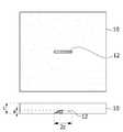
도 2는 시편에 가공된 균열을 예시적으로 보인 도면.
도 3은 다양한 미세홈 형상비(a/c)를 갖는 균열의 균열내부 위치에 따른 응력확대계수를 보인 그래프.
도 4는 다양한 미세홈 깊이비(a/t)를 갖는 균열의 균열내부 위치에 따른 응력확대계수를 보인 그래프.
도 5는 두께가 0.5mm 및 1.0mm인 시편에서의 미세홈 깊이비(a/t)에 따른 응력확대계수를 보인 그래프.
도 6은 크리프 균열성장 물성을 평가하기 위한 방법을 보인 도면.
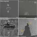
도 7은 방향성 니켈 기초 합금에 도 6의 방법을 적용한 것으로 보인 도면.1 is a cross-sectional view showing the main portion of the creep crack growth property measurement apparatus according to an embodiment of the present invention.
2 is an exemplary view showing a crack processed on a specimen.
Figure 3 is a graph showing the stress intensity factor according to the crack inner position of the crack having a variety of micro-groove shape ratio (a / c).
Figure 4 is a graph showing the stress intensity factor according to the crack inner position of the crack having a variety of micro groove depth ratio (a / t).
5 is a graph showing a stress intensity factor according to the microgroove depth ratio (a / t) in specimens having thicknesses of 0.5 mm and 1.0 mm.
6 shows a method for evaluating creep crack growth properties.
FIG. 7 shows the application of the method of FIG. 6 to a directional nickel based alloy. FIG.
본 발명은 다양한 변환을 가할 수 있고 여러 가지 실시예를 가질 수 있는 바, 특정 실시예들을 도면에 예시하고 상세하게 설명하고자 한다. 그러나, 이는 본 발명을 특정한 실시 형태에 대해 한정하려는 것이 아니며, 본 발명의 사상 및 기술 범위에 포함되는 모든 변환, 균등물 내지 대체물을 포함하는 것으로 이해되어야 한다. 본 발명을 설명함에 있어서 관련된 공지 기술에 대한 구체적인 설명이 본 발명의 요지를 흐릴 수 있다고 판단되는 경우 그 상세한 설명을 생략한다.As the invention allows for various changes and numerous embodiments, particular embodiments will be illustrated in the drawings and described in detail in the written description. However, this is not intended to limit the present invention to specific embodiments, it should be understood to include all transformations, equivalents, and substitutes included in the spirit and scope of the present invention. In the following description of the present invention, if it is determined that the detailed description of the related known technology may obscure the gist of the present invention, the detailed description thereof will be omitted.
제1, 제2 등의 용어는 다양한 구성요소들을 설명하는데 사용될 수 있지만, 상기 구성요소들은 상기 용어들에 의해 한정되어서는 안 된다. 상기 용어들은 하나의 구성요소를 다른 구성요소로부터 구별하는 목적으로만 사용된다.Terms such as first and second may be used to describe various components, but the components should not be limited by the terms. The terms are used only for the purpose of distinguishing one component from another.
본 출원에서 사용한 용어는 단지 특정한 실시 예를 설명하기 위해 사용된 것으로, 본 발명을 한정하려는 의도가 아니다. 단수의 표현은 문맥상 명백하게 다르게 뜻하지 않는 한, 복수의 표현을 포함한다. 본 출원에서, "포함한다" 또는 "가지다" 등의 용어는 명세서 상에 기재된 특징, 숫자, 단계, 동작, 구성요소, 부품 또는 이들을 조합한 것이 존재함을 지정하려는 것이지, 하나 또는 그 이상의 다른 특징들이나 숫자, 단계, 동작, 구성요소, 부품 또는 이들을 조합한 것들의 존재 또는 부가 가능성을 미리 배제하지 않는 것으로 이해되어야 한다.The terminology used herein is for the purpose of describing particular example embodiments only and is not intended to be limiting of the invention. Singular expressions include plural expressions unless the context clearly indicates otherwise. In this application, the terms "comprises" or "having" are intended to indicate that there is a feature, number, step, action, component, part, or combination thereof described on the specification, and one or more other features. It is to be understood that the present invention does not exclude the possibility of the presence or the addition of numbers, steps, operations, components, components, or a combination thereof.
이하, 본 발명에 의한 미세홈이 있는 소형시편을 이용한 크리프 균열성장 물성 측정 장치 및 방법의 일 실시예를 첨부도면을 참조하여 상세히 설명하기로 하며, 첨부 도면을 참조하여 설명함에 있어, 동일하거나 대응하는 구성 요소는 동일한 도면번호를 부여하고 이에 대한 중복되는 설명은 생략하기로 한다.Hereinafter, an embodiment of an apparatus and method for measuring creep crack growth properties using a small groove having a microgroove according to the present invention will be described in detail with reference to the accompanying drawings. The components to be assigned the same reference numerals and duplicate description thereof will be omitted.
도 1은 본 발명의 일 실시예에 따른 크리프 균열성장 물성 측정 장치의 요부를 보인 단면도이고, 도 2는 시편에 가공된 미세홈을 예시적으로 보인 도면이다.1 is a cross-sectional view showing the main portion of the creep crack growth property measurement apparatus according to an embodiment of the present invention, Figure 2 is a view showing an example of a micro groove processed in the specimen.
이에 도시된 바에 따르면, 본 발명의 일 실시예에 따른 크리프 균열성장 물성 측정 장치는 시편(10)의 가장자리가 안착되고, 중앙에는 하부 다이홀(32)이 형성되는 하부 다이(30); 하부 다이(30)의 상부에 결합되어 시편(10)을 고정시키는 상부 다이(40); 상부 다이(40)의 중앙에 형성된 상부 다이홀(42)에 삽입되어 시편(10)의 상면과 접촉하는 펀칭볼(22); 및 펀칭볼(22)의 상부를 가압하는 펀치(20)를 포함하고, 시편(10)의 하면에는 크리프 균열성장 물성측정을 위하여 반타원형의 미세홈(12)이 가공될 수 있다.According to this, the creep crack growth property measuring apparatus according to an embodiment of the present invention is the edge of the
본 실시예에서 설명하는 크리프 균열성장 물성 측정 장치는 소형 펀치 시험기(SP tester)를 일 예로 든 것이며, 소형의 시편(10)을 시험할 수 있는 장치라면 어떠한 것이라도 채용될 수 있다. 본 크리프 균열성장 물성 측정 장치는 전체적으로 실린더 형상으로 형성된다. 본 실시예에서는 소형의 시편(10)으로서 얇은 판(10mmⅩ10mmⅩ0.5mm)을 사용하였는데, 소형 시편(10)이란 두께가 2mm 이하로 충분히 얇으며 반타원형의 미세홈(12)을 가공하였을 때 미세홈(12)의 끝단 전체에 걸쳐 매개변수 값이 일정하게 유지될 수 있는 시편을 말한다.The creep crack growth property measuring apparatus described in this embodiment is a small punch tester (SP tester) as an example, any device that can test the
하부 다이(30)의 중앙에 형성된 하부 다이홀(32)은 상부로부터 가압되는 시편(10)의 처짐이 발생하면서 변형될 수 있는 공간을 형성한다. 즉, 시편(10)은 펀치(20)의 작용하중에 의해 펀칭볼(22)과 접촉하면서 미세홈(12)이 형성된 부분을 중심으로 하방으로 처짐이 발생할 수 있다. 이때, 시편(10)의 처진 부분은 하부 다이홀(32) 상에 위치함으로써 하부 다이(30)와 간섭이 발생하지 않게 된다.The
또한, 하부 다이홀(32)은 이하에서 설명하겠지만, R의 반경을 가진다. 하부 다이홀(32)의 반경 R은 응력확대계수
하부 다이(30)는 시편(10)의 가장자리가 안착되어 지지하는 역할을 하고, 하부 다이(30)의 상부에는 도 1에서와 같이 상부 다이(40)가 결합되어 시편(10)을 고정시키게 된다. 즉, 시편(10)의 가장자리는 상하면이 각각 상부 다이(40)와 하부 다이(30)에 의해 밀착되어 시편(10)이 시험과정에서 안정적으로 고정될 수 있도록 한다.The
상부 다이(40)의 중앙에도 상부 다이홀(42)이 형성되는데, 상부 다이홀(42)은 하부 다이홀(32)보다 상대적으로 작은 직경을 가진다. 상부 다이홀(42)에는 시편(10)에 하중을 가하기 위한 펀치(20)와 펀칭볼(22)이 각각 배치된다.An
펀칭볼(22)은 상부 다이홀(42) 상에서 하부에 위치하고 펀칭볼(22)의 상부는 펀치(20)에 의해 가압된다. 펀칭볼(22)은 펀치(20)에 의해 가압되면서 시편(10)의 상면과 면접촉을 하면서 시편(10)의 크리프 균열성장이 발생하도록 한다. 여기에서, 균열성장이란 미세홈(12)이 가공된 후 펀치(20)에 의해 하중이 가해지면서 발생한 균열이 성장하는 거동을 말한다.The punching
시편(10)의 크리프 균열성장을 측정하기 위해 시편(10)의 표면, 즉 하면에는 미세홈(12)이 가공된다. 미세홈(12)은 시편(10)의 하면에 레이저 등을 이용하여 형성되는 것으로서, 도 1 및 도 2에서와 같이 반타원형으로 형성될 수 있다. 물론, 미세홈(12)은 상술한 레이저에 의해서만 형성되는 것은 아니고 아래에서 설명할 조건만 만족한다면 어떠한 수단을 이용하여 형성하더라도 관계없다.In order to measure creep crack growth of the
본 실시예에서 시편(10)에 형성하는 미세홈(12)을 반타원형으로 형성한 것은 최초에 형성된 미세홈(12) 형상에서 시간이 경과함에 따라 미세홈(12)이 성장방향에 대하여 끝단에서 균일한 속도로 성장되도록 하기 위함이다. 예를 들어, 미세홈(12)이 직사각형 형상으로 형성될 경우에는 중앙부에서의 균열성장과 양측부에서의 균열성장이 서로 다르기 때문에 미세홈(12)의 성장을 균일하게 파악할 수 없는 문제가 없다. 따라서, 본 실시예에서는 미세홈(12)이 방사상으로 균일하게 성장할 수 있도록 반타원형으로 형성한 것이다.In the present embodiment, the
다음으로, 시편(10)의 시험을 위한 미세홈(12) 형상의 적절한 범위는 탄성 유한요소해석 등을 통해 결정된다. 이하에서는 유한요소해석을 통해 얻은 매개변수의 범위에 대해서 설명하고자 한다.Next, the appropriate range of the shape of the
먼저, 응력확대계수

[수학식1][Equation 1]


(K: 응력확대계수, v: 프아송의 비, P: 작용하중, t: 시편두께, R: 하부 다이홀의 반경, r: 시편과 작용하중을 받는 펀칭수단(펀칭볼)의 접촉면적의 반경, a: 미세홈 깊이, c: 미세홈 폭의 1/2, Φ: 미세홈 부분의 각도, Fsp : 보정계수)(K: stress intensity factor, v: Poisson's ratio, P: working load, t: specimen thickness, R: radius of lower die hole, r: radius of contact area between specimen and punching means (punching ball) subjected to working load, a: microgroove depth, c: 1/2 of microgroove width, Φ: angle of microgroove, Fsp : correction factor)
삭제delete
삭제delete
삭제delete
삭제delete
한편, 파괴매개변수
[수학식3] [Equation 3]

여기에서

삭제delete
삭제delete
삭제delete
삭제delete
이하에서는 도 3 내지 도 7을 참조하여 상술한 매개변수에 대한 실제 실험결과에 대해서 살펴보기로 한다.Hereinafter, the actual experimental results for the above-described parameters will be described with reference to FIGS. 3 to 7.
도 3은 다양한 미세홈 형상비(a/c)를 갖는 균열의 균열내부 위치에 따른 응력확대계수를 보인 그래프이고, 도 4는 다양한 미세홈 깊이비(a/t)를 갖는 균열의 균열내부 위치에 따른 응력확대계수를 보인 그래프이며, 도 5는 두께가 0.5mm 및 1.0mm인 시편에서의 미세홈 깊이비(a/t)에 따른 응력확대계수를 보인 그래프이고, 도 6은 크리프 균열성장 물성을 평가하기 위한 방법을 보인 도면이며, 도 7은 방향성 니켈 기초 합금에 도 6의 방법을 적용한 것으로 보인 도면이다.Figure 3 is a graph showing the stress intensity factor according to the crack inner position of the crack having various microgroove shape ratio (a / c), Figure 4 is a crack inner position of the crack having various microgroove depth ratio (a / t) 5 is a graph showing stress intensity factor according to the present invention, FIG. 5 is a graph showing stress intensity factor according to the microgroove depth ratio (a / t) in specimens having thicknesses of 0.5 mm and 1.0 mm, and FIG. FIG. 7 shows a method for evaluation, and FIG. 7 is a diagram showing the method of FIG. 6 applied to a directional nickel-based alloy.
도 3을 참조하면, 응력확대계수
도 4를 참조하면, 시편(10)의 두께에 대해 미세홈 깊이비(a/t)가 0.10에서 0.30의 범위에서 미세홈 깊이비가 증가할수록


도 5를 참조하면, 본 실시예에서 제안하는 시편(10)을 이용한 크리프 균열성장 시험에서 시편(10) 두께에 대한 미세홈 깊이비(a/t)의 최적 범위는 0.10에서 0.30이다. 이는 다른 조건하에서 유한요소해석을 하였을 때, 미세홈 깊이비의 최적 범위 내에서


도 6 및 도 7을 참조하면, 유한요소해석으로 얻은 균열 매개변수를 기반으로, 시편(10)은 레이저에 의해 미세홈(12)이 가공된다. 본 실시예에 따른 크리프 균열성장 시험방법은 미세홈(12)이 성장하는 도중에 시험을 중지하고, 주사전자현미경(SEM) 또는 금속현미경을 통해 최종 균열 길이를 측정한다. 이와 같이, 현미경을 통해 구한 초기 균열길이와 최종 균열길이 그리고 시험시간으로 구한 평균 균열성장률은


이상에서 살펴본 균열 가공법을 이용하여 시편을 가공하고 정하중으로 다양한 조건 하에서 소형펀치 크리프 시험을 수행할 수 있다. 그리고, 금속학적 미세조직분석을 통해 크리프 균열 성장률을 평가할 수 있고, 소형펀치 시험으로 얻은 결과와 기존의 크리프 균열성장 시험으로 얻은 결과의 상관관계 함수를 도출할 수 있다. 그러면, 기존의 시험법으로 크리프 균열성장 거동을 평가하기 어려운 설비와 구조물의 열 영향부 또는 두께가 얇은 부품과 같은 조건에서의 크리프 균열성장 특성을 직접 측정할 수 있는 장점이 있다.By using the above-described crack processing method, the small punch creep test can be performed under various conditions with the static load. In addition, it is possible to evaluate the creep crack growth rate through the metallurgical microstructure analysis, and to derive a correlation function between the results obtained by the small punch test and the results obtained by the conventional creep crack growth test. Then, there is an advantage that it is possible to directly measure the creep crack growth characteristics under conditions such as heat affected zones or thin parts of equipment and structures that are difficult to evaluate the creep crack growth behavior by conventional test methods.
상기에서는 본 발명의 특정의 실시예를 참조하여 설명하였지만, 해당 기술 분야에서 통상의 지식을 가진 자라면 하기의 특허 청구의 범위에 기재된 본 발명의 사상 및 영역으로부터 벗어나지 않는 범위 내에서 본 발명을 다양하게 수정 및 변경시킬 수 있음을 이해할 수 있을 것이다.Although the foregoing has been described with reference to specific embodiments of the present invention, those skilled in the art may vary the present invention without departing from the spirit and scope of the present invention as set forth in the claims below. It will be understood that modifications and changes can be made.
10 : 시편12 : 미세홈
20 : 펀치22 : 펀칭볼
30 : 하부 다이32 : 하부 다이홀
40 : 상부 다이42 : 상부 다이홀10: Psalm 12: microgroove
20: Punch 22: Punching Ball
30: lower die 32: lower die hole
40: upper die 42: upper die hole
Claims (14)
Translated fromKorean상기 시편의 가장자리가 안착되고, 중앙에는 하부 다이홀이 형성되는 하부 다이;
상기 하부 다이의 상부에 결합되어 상기 시편을 고정시키는 상부 다이; 및
상기 상부 다이의 중앙에 형성된 상부 다이홀에 삽입되어 상기 시편의 상면을 가압하는 펀칭수단을 포함하고,
상기 시편의 하면에는 크리프 균열성장 물성측정을 위하여 반타원형의 미세홈이 가공되며,
상기 시편의 미세홈은 하기 [수학식1]의 응력확대계수를 계산하고 치수를 결정하여 가공되는 것을 특징으로 하는 미세홈이 있는 소형시편을 이용한 크리프 균열성장 물성 측정 장치.
[수학식1]

(K: 응력확대계수, v: 프아송의 비, P: 작용하중, t: 시편두께, R: 하부 다이홀의 반경, r: 시편과 작용하중을 받는 펀칭수단의 접촉면적의 반경, a: 미세홈 깊이, c: 미세홈 폭의 1/2, Φ: 미세홈 부분의 각도, Fsp : 보정계수)In the physical property measuring device for measuring creep crack growth of small specimens,
A lower die on which an edge of the specimen is seated and a lower die hole is formed in the center of the specimen;
An upper die coupled to an upper portion of the lower die to fix the specimen; And
A punching means inserted into the upper die hole formed in the center of the upper die to press the upper surface of the specimen;
The lower surface of the specimen is machined with a semi-elliptic micro groove for measuring creep crack growth properties,
The microgroove of the specimen is a creep crack growth property measurement apparatus using a small specimen with a microgroove, characterized in that the processing is calculated by calculating the stress intensity factor of the following [Equation 1] and determine the dimensions.
[Equation 1]
(K: Stress Intensity Factor, v: Poisson's Ratio, P: Working Load, t: Specimen Thickness, R: Radius of Lower Die Hole, r: Radius of Contact Area of Specimens and Punching Means Subjected to Working Load, a: Fine Groove depth, c: 1/2 of microgroove width, Φ: angle of microgroove, Fsp : correction factor)
상기 펀칭수단은,
상기 상부 다이홀에 삽입되어 상기 시편의 상면과 접촉하는 펀칭볼; 및
상기 펀칭볼의 상부를 가압하는 펀치를 포함하는 것을 특징으로 하는 미세홈이 있는 소형시편을 이용한 크리프 균열성장 물성 측정 장치.The method of claim 1,
The punching means,
A punching ball inserted into the upper die hole and contacting an upper surface of the specimen; And
Creep crack growth property measurement apparatus using a small specimen having a micro-groove, characterized in that it comprises a punch for pressing the upper portion of the punching ball.
상기 미세홈은 레이저를 이용하여 가공되는 것을 특징으로 하는 미세홈이 있는 소형시편을 이용한 크리프 균열성장 물성 측정 장치.The method of claim 1,
The microgroove is a creep crack growth property measuring apparatus using a small specimen having a microgroove, characterized in that the processing using a laser.
상기 응력확대계수의 미세홈 형상비(a/c)는 0.5인 것을 특징으로 하는 미세홈이 있는 소형시편을 이용한 크리프 균열성장 물성 측정 장치.The method of claim 1,
The microgroove shape ratio (a / c) of the stress intensity factor is a creep crack growth property measurement apparatus using a small specimen with a microgroove, characterized in that 0.5.
상기 응력확대계수에서 미세홈 깊이비(a/t)는 0.1 내지 0.3인 것을 특징으로 하는 미세홈이 있는 소형시편을 이용한 크리프 균열성장 물성 측정 장치.The method of claim 1,
Creep crack growth property measurement apparatus using a small groove having a micro-groove, characterized in that the microgroove depth ratio (a / t) in the stress intensity factor is 0.1 to 0.3.
상기 시편의 표면에 크리프 균열성장을 위하여 반타원형으로 미세홈을 가공하는 단계; 및
상기 시편에 하중을 가하여 크리프의 균열성장 물성에 대한 데이터를 획득하는 단계를 포함하고,
상기 시편의 미세홈은 하기 [수학식1]의 응력확대계수를 계산하고 치수를 결정하여 가공되는 것을 특징으로 하는 미세홈이 있는 소형시편을 이용한 크리프 균열성장 물성 측정 방법.
[수학식1]

(K: 응력확대계수, v: 프아송의 비, P: 작용하중, t: 시편두께, R: 하부 다이홀의 반경, r: 시편과 작용하중을 받는 펀칭수단의 접촉면적의 반경, a: 미세홈 깊이, c: 미세홈 폭의 1/2, Φ: 미세홈 부분의 각도, Fsp : 보정계수)In the physical property measurement method for measuring creep crack growth of small specimens,
Processing a microgroove in a semi-elliptic shape for creep crack growth on the surface of the specimen; And
Applying a load to the specimen to obtain data on creep crack growth properties;
The microgroove of the specimen is a method of measuring creep crack growth properties using a small specimen having a microgroove, characterized in that the processing is calculated by calculating the stress intensity factor of the following [Equation 1] and determining the dimensions.
[Equation 1]
(K: Stress Intensity Factor, v: Poisson's Ratio, P: Working Load, t: Specimen Thickness, R: Radius of Lower Die Hole, r: Radius of Contact Area of Specimens and Punching Means Subjected to Working Load, a: Fine Groove depth, c: 1/2 of microgroove width, Φ: angle of microgroove, Fsp : correction factor)
상기 응력확대계수의 미세홈 형상비(a/c)는 0.5인 것을 특징으로 하는 미세홈이 있는 소형시편을 이용한 크리프 균열성장 물성 측정 방법.The method of claim 9,
The method of measuring creep crack growth properties using a small groove having a microgroove, wherein the microgroove shape ratio (a / c) of the stress intensity factor is 0.5.
상기 응력확대계수에서 미세홈 깊이비(a/t)는 0.1 내지 0.3인 것을 특징으로 하는 미세홈이 있는 소형시편을 이용한 크리프 균열성장 물성 측정 방법.The method of claim 9,
A creep crack growth property measurement method using a small groove having a microgroove, wherein the microgroove depth ratio (a / t) in the stress intensity factor is 0.1 to 0.3.
Priority Applications (3)
| Application Number | Priority Date | Filing Date | Title |
|---|---|---|---|
| KR1020170062471AKR102047065B1 (en) | 2017-05-19 | 2017-05-19 | Estimation Apparatus and Method of Creep Crack Rate and Relevant Growth Fracture Parameters for Small Punch Specimen with a Micro Groove |
| PCT/KR2017/005295WO2018212387A1 (en) | 2017-05-19 | 2017-05-22 | Device and method for measuring creep crack growth properties by using small specimen having fine groove |
| US16/614,157US11598705B2 (en) | 2017-05-19 | 2017-05-22 | Apparatus and method for measuring creep crack growth property using small specimen with micro groove |
Applications Claiming Priority (1)
| Application Number | Priority Date | Filing Date | Title |
|---|---|---|---|
| KR1020170062471AKR102047065B1 (en) | 2017-05-19 | 2017-05-19 | Estimation Apparatus and Method of Creep Crack Rate and Relevant Growth Fracture Parameters for Small Punch Specimen with a Micro Groove |
Publications (2)
| Publication Number | Publication Date |
|---|---|
| KR20180127095A KR20180127095A (en) | 2018-11-28 |
| KR102047065B1true KR102047065B1 (en) | 2019-11-21 |
Family
ID=64274072
Family Applications (1)
| Application Number | Title | Priority Date | Filing Date |
|---|---|---|---|
| KR1020170062471AActiveKR102047065B1 (en) | 2017-05-19 | 2017-05-19 | Estimation Apparatus and Method of Creep Crack Rate and Relevant Growth Fracture Parameters for Small Punch Specimen with a Micro Groove |
Country Status (3)
| Country | Link |
|---|---|
| US (1) | US11598705B2 (en) |
| KR (1) | KR102047065B1 (en) |
| WO (1) | WO2018212387A1 (en) |
Cited By (1)
| Publication number | Priority date | Publication date | Assignee | Title |
|---|---|---|---|---|
| KR20230031663A (en)* | 2021-08-27 | 2023-03-07 | 한국원자력연구원 | Method and apparatus for extracting creep curve under constant stress condition |
Families Citing this family (6)
| Publication number | Priority date | Publication date | Assignee | Title |
|---|---|---|---|---|
| CN109813594A (en)* | 2019-01-31 | 2019-05-28 | 中国矿业大学 | A small punch test device and method for deep-sea hydrogen-induced stress cracking behavior |
| CN112179753A (en)* | 2020-09-16 | 2021-01-05 | 西安交通大学 | Device and method for evaluating ductile-brittle transition behavior of metal material |
| CN112360448B (en)* | 2020-11-23 | 2021-06-18 | 西南石油大学 | A method for determining the well soaking time after fracturing by using the creep propagation of hydraulic fractures |
| KR102456685B1 (en)* | 2021-02-16 | 2022-10-19 | 부산대학교 산학협력단 | Method of measuring fracture toughness considering the plastic rotational factor based on double clip gauge |
| CN113376042A (en)* | 2021-06-17 | 2021-09-10 | 福州大学 | Test method for determining crack starting point of notched test specimen |
| CN118477936A (en)* | 2024-05-14 | 2024-08-13 | 东风汽车集团股份有限公司 | Design method of anti-cracking automobile stamping die |
Citations (1)
| Publication number | Priority date | Publication date | Assignee | Title |
|---|---|---|---|---|
| JP2014077696A (en) | 2012-10-10 | 2014-05-01 | Mitsubishi Heavy Ind Ltd | Creep test device and creep test method |
Family Cites Families (8)
| Publication number | Priority date | Publication date | Assignee | Title |
|---|---|---|---|---|
| CA2306275C (en)* | 1999-04-23 | 2009-11-03 | Bio Syntech Canada Inc. | Universal mechanical testing device |
| KR100367843B1 (en)* | 2000-03-03 | 2003-01-10 | 한국수력원자력 주식회사 | Small punch creep test device with small specimen |
| GB2383848B (en)* | 2000-08-16 | 2004-07-28 | Chugoku Electric Power | Creep life evaluation method |
| KR100919003B1 (en)* | 2002-12-23 | 2009-09-24 | 재단법인 포항산업과학연구원 | Two-stage separate pusher rod for small punch creep tester |
| JP2010014600A (en)* | 2008-07-04 | 2010-01-21 | Kansai Electric Power Co Inc:The | Test piece for estimating creep lifetime, and estimation method of creep lifetime using the same |
| US8042405B2 (en)* | 2008-07-23 | 2011-10-25 | University Of Kentucky Research Foundation | Method and apparatus for characterizing microscale formability of thin sheet materials |
| KR100985601B1 (en)* | 2008-11-04 | 2010-10-06 | 중앙대학교 산학협력단 | Local strength measuring device with surface shape measuring device and measuring method of specimen strength using same |
| KR101198392B1 (en)* | 2010-07-27 | 2012-11-07 | 케이.엘.이.에스 주식회사 | Creep tester of small punch type |
- 2017
- 2017-05-19KRKR1020170062471Apatent/KR102047065B1/enactiveActive
- 2017-05-22WOPCT/KR2017/005295patent/WO2018212387A1/ennot_activeCeased
- 2017-05-22USUS16/614,157patent/US11598705B2/enactiveActive
Patent Citations (1)
| Publication number | Priority date | Publication date | Assignee | Title |
|---|---|---|---|---|
| JP2014077696A (en) | 2012-10-10 | 2014-05-01 | Mitsubishi Heavy Ind Ltd | Creep test device and creep test method |
Non-Patent Citations (2)
| Title |
|---|
| 손현성 외. 판재의 성형한계에 대한 변형경로 의존성에 대한 연구. 한국자동차공학회 춘추계 학술대회 논문집. 한국자동차공학회. 2000년05월. 페이지 468-473 |
| 장상엽 외, 소형 펀치시험을 이용한 금속배관 취성평가, 한국에너지학회 2017년도 춘계학술발표회, 한국에너지학회, 2017. 4. pp19-19 |
Cited By (2)
| Publication number | Priority date | Publication date | Assignee | Title |
|---|---|---|---|---|
| KR20230031663A (en)* | 2021-08-27 | 2023-03-07 | 한국원자력연구원 | Method and apparatus for extracting creep curve under constant stress condition |
| KR102514604B1 (en) | 2021-08-27 | 2023-03-27 | 한국원자력연구원 | Method and apparatus for extracting creep curve under constant stress condition |
Also Published As
| Publication number | Publication date |
|---|---|
| KR20180127095A (en) | 2018-11-28 |
| US20210063292A1 (en) | 2021-03-04 |
| WO2018212387A1 (en) | 2018-11-22 |
| US11598705B2 (en) | 2023-03-07 |
Similar Documents
| Publication | Publication Date | Title |
|---|---|---|
| KR102047065B1 (en) | Estimation Apparatus and Method of Creep Crack Rate and Relevant Growth Fracture Parameters for Small Punch Specimen with a Micro Groove | |
| Arunkumar | Overview of small punch test | |
| JP5435352B2 (en) | Method for determining the breaking strain of plate materials | |
| KR101716492B1 (en) | Method for determining reheat cracking susceptibility | |
| US10274407B2 (en) | Method of evaluating stretch-flangeability with small-scale specimen without specimen size effects | |
| US20150377757A1 (en) | Small Two bar specimen (TBS) | |
| Moreno | Application of small punch testing on the mechanical and microstructural characterizations of P91 steel at room temperature | |
| KR102787903B1 (en) | Indentation test method | |
| García et al. | Estimation of the fracture toughness of structural steels by means of the CTOD evaluation on notched small punch specimens | |
| RU2238535C2 (en) | Method of determining resistance of material to damaging | |
| JP2020059058A (en) | Conjugate manufacturing method and management method for plate-like member quality | |
| Kobayashi et al. | Deformation and fracture mode during small punch creep tests | |
| JP2008292234A (en) | Young's modulus calculation, analysis and calibrating method utilizing instrumented indentation test | |
| CN115791475A (en) | Metal material plasticity parameter obtaining method based on spherical pressing-in method | |
| JP7388201B2 (en) | Stress evaluation method, bending workability evaluation method, and metal member manufacturing method | |
| KR20120033186A (en) | Method of correcting indentation curve by considering worn indenter's morphology | |
| Hurst et al. | A renaissance in Small Punch testing at Swansea University | |
| Prakash et al. | Evaluation of fatigue data through miniature specimen test techniques | |
| Xu et al. | Detecting secondary to tertiary creep transitions by acoustic emission | |
| KR20020051073A (en) | Test method for brittle fracture of cold rolled steel sheet after forming | |
| KR101685507B1 (en) | Test method of interfacial adhesion | |
| RU2835377C1 (en) | Method for assessing the nature of fracture of an alloy using fractal analysis | |
| RU2838331C1 (en) | Method of determining critical temperature of brittleness of pipeline material | |
| RU2344407C1 (en) | Method of testing biaxial stretching of sheet material | |
| KR20080102790A (en) | Fatigue property evaluation device of pipe material |
Legal Events
| Date | Code | Title | Description |
|---|---|---|---|
| PA0109 | Patent application | Patent event code:PA01091R01D Comment text:Patent Application Patent event date:20170519 | |
| PA0201 | Request for examination | ||
| PE0902 | Notice of grounds for rejection | Comment text:Notification of reason for refusal Patent event date:20180228 Patent event code:PE09021S01D | |
| AMND | Amendment | ||
| E902 | Notification of reason for refusal | ||
| PE0902 | Notice of grounds for rejection | Comment text:Notification of reason for refusal Patent event date:20181128 Patent event code:PE09021S01D | |
| PG1501 | Laying open of application | ||
| AMND | Amendment | ||
| E90F | Notification of reason for final refusal | ||
| PE0902 | Notice of grounds for rejection | Comment text:Final Notice of Reason for Refusal Patent event date:20190708 Patent event code:PE09021S02D | |
| E601 | Decision to refuse application | ||
| PE0601 | Decision on rejection of patent | Patent event date:20190917 Comment text:Decision to Refuse Application Patent event code:PE06012S01D Patent event date:20190708 Comment text:Final Notice of Reason for Refusal Patent event code:PE06011S02I Patent event date:20181128 Comment text:Notification of reason for refusal Patent event code:PE06011S01I Patent event date:20180228 Comment text:Notification of reason for refusal Patent event code:PE06011S01I | |
| AMND | Amendment | ||
| PX0901 | Re-examination | Patent event code:PX09011S01I Patent event date:20190917 Comment text:Decision to Refuse Application Patent event code:PX09012R01I Patent event date:20190228 Comment text:Amendment to Specification, etc. Patent event code:PX09012R01I Patent event date:20180702 Comment text:Amendment to Specification, etc. | |
| PX0701 | Decision of registration after re-examination | Patent event date:20191112 Comment text:Decision to Grant Registration Patent event code:PX07013S01D Patent event date:20191017 Comment text:Amendment to Specification, etc. Patent event code:PX07012R01I Patent event date:20190917 Comment text:Decision to Refuse Application Patent event code:PX07011S01I Patent event date:20190228 Comment text:Amendment to Specification, etc. Patent event code:PX07012R01I Patent event date:20180702 Comment text:Amendment to Specification, etc. Patent event code:PX07012R01I | |
| X701 | Decision to grant (after re-examination) | ||
| PR0701 | Registration of establishment | Comment text:Registration of Establishment Patent event date:20191114 Patent event code:PR07011E01D | |
| PR1002 | Payment of registration fee | Payment date:20191115 End annual number:3 Start annual number:1 | |
| PG1601 | Publication of registration | ||
| PR1001 | Payment of annual fee | Payment date:20221201 Start annual number:4 End annual number:4 | |
| PR1001 | Payment of annual fee | Payment date:20230921 Start annual number:5 End annual number:5 | |
| PR1001 | Payment of annual fee | Payment date:20241007 Start annual number:6 End annual number:6 |