KR102037745B1 - Ingot clamping device and wire sawing apparatus for cutting Ingot having the same - Google Patents
Ingot clamping device and wire sawing apparatus for cutting Ingot having the sameDownload PDFInfo
- Publication number
- KR102037745B1 KR102037745B1KR1020170171904AKR20170171904AKR102037745B1KR 102037745 B1KR102037745 B1KR 102037745B1KR 1020170171904 AKR1020170171904 AKR 1020170171904AKR 20170171904 AKR20170171904 AKR 20170171904AKR 102037745 B1KR102037745 B1KR 102037745B1
- Authority
- KR
- South Korea
- Prior art keywords
- ingot
- clamp
- cavity
- air
- cover
- Prior art date
- Legal status (The legal status is an assumption and is not a legal conclusion. Google has not performed a legal analysis and makes no representation as to the accuracy of the status listed.)
- Active
Links
- 238000005520cutting processMethods0.000titleclaimsdescription14
- 230000033001locomotionEffects0.000claimsabstractdescription12
- 238000000034methodMethods0.000claimsdescription48
- 239000002002slurrySubstances0.000claimsdescription35
- 230000008878couplingEffects0.000claimsdescription10
- 238000010168coupling processMethods0.000claimsdescription10
- 238000005859coupling reactionMethods0.000claimsdescription10
- 238000002347injectionMethods0.000claimsdescription8
- 239000007924injectionSubstances0.000claimsdescription8
- 239000007921spraySubstances0.000claimsdescription6
- 238000005507sprayingMethods0.000claimsdescription4
- 235000012431wafersNutrition0.000description18
- 239000002245particleSubstances0.000description8
- 239000012535impuritySubstances0.000description6
- 239000000243solutionSubstances0.000description6
- 238000011109contaminationMethods0.000description4
- 239000013078crystalSubstances0.000description4
- 239000002923metal particleSubstances0.000description4
- XUIMIQQOPSSXEZ-UHFFFAOYSA-NSiliconChemical compound[Si]XUIMIQQOPSSXEZ-UHFFFAOYSA-N0.000description3
- 238000003825pressingMethods0.000description3
- 238000007789sealingMethods0.000description3
- 229910052710siliconInorganic materials0.000description3
- 239000010703siliconSubstances0.000description3
- 239000006061abrasive grainSubstances0.000description2
- 238000010586diagramMethods0.000description2
- 229910003460diamondInorganic materials0.000description2
- 239000010432diamondSubstances0.000description2
- 230000000694effectsEffects0.000description2
- 238000004519manufacturing processMethods0.000description2
- 229910021421monocrystalline siliconInorganic materials0.000description2
- 230000000149penetrating effectEffects0.000description2
- 239000004065semiconductorSubstances0.000description2
- 230000002411adverseEffects0.000description1
- 238000004140cleaningMethods0.000description1
- 239000000356contaminantSubstances0.000description1
- 230000006837decompressionEffects0.000description1
- 230000006866deteriorationEffects0.000description1
- 235000012489doughnutsNutrition0.000description1
- 238000005530etchingMethods0.000description1
- 239000010720hydraulic oilSubstances0.000description1
- 238000002844meltingMethods0.000description1
- 230000008018meltingEffects0.000description1
- 238000012986modificationMethods0.000description1
- 230000004048modificationEffects0.000description1
- 238000012856packingMethods0.000description1
- 230000035515penetrationEffects0.000description1
- 230000002093peripheral effectEffects0.000description1
- 238000005498polishingMethods0.000description1
- 238000007517polishing processMethods0.000description1
- 229910021420polycrystalline siliconInorganic materials0.000description1
- 229920001296polysiloxanePolymers0.000description1
- 238000012545processingMethods0.000description1
- 238000010926purgeMethods0.000description1
- 239000011856silicon-based particleSubstances0.000description1
- 238000003756stirringMethods0.000description1
- 239000000758substrateSubstances0.000description1
- 238000012546transferMethods0.000description1
- 230000003313weakening effectEffects0.000description1
Images


Classifications
- H—ELECTRICITY
- H01—ELECTRIC ELEMENTS
- H01L—SEMICONDUCTOR DEVICES NOT COVERED BY CLASS H10
- H01L21/00—Processes or apparatus adapted for the manufacture or treatment of semiconductor or solid state devices or of parts thereof
- H01L21/67—Apparatus specially adapted for handling semiconductor or electric solid state devices during manufacture or treatment thereof; Apparatus specially adapted for handling wafers during manufacture or treatment of semiconductor or electric solid state devices or components ; Apparatus not specifically provided for elsewhere
- H01L21/683—Apparatus specially adapted for handling semiconductor or electric solid state devices during manufacture or treatment thereof; Apparatus specially adapted for handling wafers during manufacture or treatment of semiconductor or electric solid state devices or components ; Apparatus not specifically provided for elsewhere for supporting or gripping
- H01L21/687—Apparatus specially adapted for handling semiconductor or electric solid state devices during manufacture or treatment thereof; Apparatus specially adapted for handling wafers during manufacture or treatment of semiconductor or electric solid state devices or components ; Apparatus not specifically provided for elsewhere for supporting or gripping using mechanical means, e.g. chucks, clamps or pinches
- B—PERFORMING OPERATIONS; TRANSPORTING
- B28—WORKING CEMENT, CLAY, OR STONE
- B28D—WORKING STONE OR STONE-LIKE MATERIALS
- B28D5/00—Fine working of gems, jewels, crystals, e.g. of semiconductor material; apparatus or devices therefor
- B28D5/0058—Accessories specially adapted for use with machines for fine working of gems, jewels, crystals, e.g. of semiconductor material
- B28D5/0082—Accessories specially adapted for use with machines for fine working of gems, jewels, crystals, e.g. of semiconductor material for supporting, holding, feeding, conveying or discharging work
- B—PERFORMING OPERATIONS; TRANSPORTING
- B28—WORKING CEMENT, CLAY, OR STONE
- B28D—WORKING STONE OR STONE-LIKE MATERIALS
- B28D5/00—Fine working of gems, jewels, crystals, e.g. of semiconductor material; apparatus or devices therefor
- B28D5/0058—Accessories specially adapted for use with machines for fine working of gems, jewels, crystals, e.g. of semiconductor material
- B28D5/007—Use, recovery or regeneration of abrasive mediums
- B—PERFORMING OPERATIONS; TRANSPORTING
- B28—WORKING CEMENT, CLAY, OR STONE
- B28D—WORKING STONE OR STONE-LIKE MATERIALS
- B28D5/00—Fine working of gems, jewels, crystals, e.g. of semiconductor material; apparatus or devices therefor
- B28D5/0058—Accessories specially adapted for use with machines for fine working of gems, jewels, crystals, e.g. of semiconductor material
- B28D5/0076—Accessories specially adapted for use with machines for fine working of gems, jewels, crystals, e.g. of semiconductor material for removing dust, e.g. by spraying liquids; for lubricating, cooling or cleaning tool or work
- B—PERFORMING OPERATIONS; TRANSPORTING
- B28—WORKING CEMENT, CLAY, OR STONE
- B28D—WORKING STONE OR STONE-LIKE MATERIALS
- B28D5/00—Fine working of gems, jewels, crystals, e.g. of semiconductor material; apparatus or devices therefor
- B28D5/04—Fine working of gems, jewels, crystals, e.g. of semiconductor material; apparatus or devices therefor by tools other than rotary type, e.g. reciprocating tools
- B28D5/042—Fine working of gems, jewels, crystals, e.g. of semiconductor material; apparatus or devices therefor by tools other than rotary type, e.g. reciprocating tools by cutting with blades or wires mounted in a reciprocating frame
- B—PERFORMING OPERATIONS; TRANSPORTING
- B28—WORKING CEMENT, CLAY, OR STONE
- B28D—WORKING STONE OR STONE-LIKE MATERIALS
- B28D7/00—Accessories specially adapted for use with machines or devices of the preceding groups
- B28D7/04—Accessories specially adapted for use with machines or devices of the preceding groups for supporting or holding work or conveying or discharging work
- H—ELECTRICITY
- H01—ELECTRIC ELEMENTS
- H01L—SEMICONDUCTOR DEVICES NOT COVERED BY CLASS H10
- H01L21/00—Processes or apparatus adapted for the manufacture or treatment of semiconductor or solid state devices or of parts thereof
- H01L21/67—Apparatus specially adapted for handling semiconductor or electric solid state devices during manufacture or treatment thereof; Apparatus specially adapted for handling wafers during manufacture or treatment of semiconductor or electric solid state devices or components ; Apparatus not specifically provided for elsewhere
- H01L21/67005—Apparatus not specifically provided for elsewhere
- H01L21/67011—Apparatus for manufacture or treatment
- H01L21/67092—Apparatus for mechanical treatment
- B—PERFORMING OPERATIONS; TRANSPORTING
- B28—WORKING CEMENT, CLAY, OR STONE
- B28D—WORKING STONE OR STONE-LIKE MATERIALS
- B28D5/00—Fine working of gems, jewels, crystals, e.g. of semiconductor material; apparatus or devices therefor
- B28D5/04—Fine working of gems, jewels, crystals, e.g. of semiconductor material; apparatus or devices therefor by tools other than rotary type, e.g. reciprocating tools
- B28D5/045—Fine working of gems, jewels, crystals, e.g. of semiconductor material; apparatus or devices therefor by tools other than rotary type, e.g. reciprocating tools by cutting with wires or closed-loop blades
- Y—GENERAL TAGGING OF NEW TECHNOLOGICAL DEVELOPMENTS; GENERAL TAGGING OF CROSS-SECTIONAL TECHNOLOGIES SPANNING OVER SEVERAL SECTIONS OF THE IPC; TECHNICAL SUBJECTS COVERED BY FORMER USPC CROSS-REFERENCE ART COLLECTIONS [XRACs] AND DIGESTS
- Y02—TECHNOLOGIES OR APPLICATIONS FOR MITIGATION OR ADAPTATION AGAINST CLIMATE CHANGE
- Y02P—CLIMATE CHANGE MITIGATION TECHNOLOGIES IN THE PRODUCTION OR PROCESSING OF GOODS
- Y02P70/00—Climate change mitigation technologies in the production process for final industrial or consumer products
- Y02P70/10—Greenhouse gas [GHG] capture, material saving, heat recovery or other energy efficient measures, e.g. motor control, characterised by manufacturing processes, e.g. for rolling metal or metal working
Landscapes
- Engineering & Computer Science (AREA)
- Mechanical Engineering (AREA)
- Computer Hardware Design (AREA)
- Condensed Matter Physics & Semiconductors (AREA)
- General Physics & Mathematics (AREA)
- Manufacturing & Machinery (AREA)
- Physics & Mathematics (AREA)
- Microelectronics & Electronic Packaging (AREA)
- Power Engineering (AREA)
- Processing Of Stones Or Stones Resemblance Materials (AREA)
- Mechanical Treatment Of Semiconductor (AREA)
- Finish Polishing, Edge Sharpening, And Grinding By Specific Grinding Devices (AREA)
- Jigs For Machine Tools (AREA)
- Constituent Portions Of Griding Lathes, Driving, Sensing And Control (AREA)
- Grinding-Machine Dressing And Accessory Apparatuses (AREA)
Abstract
Translated fromKoreanDescription
Translated fromKorean본 발명은 반도체 웨이퍼 제조 장치에 관한 것으로, 보다 상세하게는 잉곳 절단용 와이어 쏘잉 장치에 관한 것이다.The present invention relates to a semiconductor wafer manufacturing apparatus, and more particularly to a wire sawing apparatus for cutting ingots.
반도체 웨이퍼는 단결정 실리콘 잉곳(ingot)을 웨이퍼 형태로 얇게 절단하는 슬라이싱 공정, 원하는 두께로 연마하면서 평탄도를 개선하는 래핑 공정(lapping), 웨이퍼 내부의 손상층 제거를 위한 식각 공정(etching), 표면 경면화 및 평탄도를 향상시키기 위한 폴리싱 공정(polishing), 웨이퍼 표면의 오염물질을 제거하기 위한 세정 공정(cleaning) 등의 단계를 거쳐 웨이퍼로 생산된다.Semiconductor wafers include a slicing process for thinly cutting single crystal silicon ingots into wafer form, a lapping process for improving flatness while polishing to a desired thickness, an etching process for removing damage layers inside the wafer, and a surface It is produced into a wafer through a polishing process to improve mirroring and flatness, and a cleaning process to remove contaminants on the wafer surface.
단결정 실리콘 잉곳은 일반적으로 쵸크랄스키법(Czochralski method)에 따라 성장되어 제조된다. 이 방법은 챔버 내의 도가니에서 다결정 실리콘을 용융시키고, 용융된 실리콘에 단결정인 종자 결정(seed crystal)을 담근 후, 이를 서서히 상승시키면서 원하는 지름의 실리콘 단결정 잉곳으로 성장시키는 방법이다.Single crystal silicon ingots are generally grown and manufactured according to the Czochralski method. This method is a method of melting polycrystalline silicon in a crucible in a chamber, immersing the seed crystal as a single crystal in the molten silicon, and growing it into a silicon single crystal ingot of a desired diameter while gradually raising it.
상술한 바와 같이 잉곳의 성장이 완료된 후에는, 잉곳을 웨이퍼 단위로 절단하는 슬라이싱 공정(slicing process)이 진행된다.As described above, after the growth of the ingot is completed, a slicing process of cutting the ingot in wafer units is performed.
슬라이싱 공정은 여러 가지 방식이 있는데, 박판 외주 부분에 다이아몬드 입자를 고착시켜 잉곳을 절단하는 O.D.S(Out Diameter Saw) 방식, 도넛(doughnut)형의 박판 내주에 다이아몬드 입자를 고착시켜 잉곳을 절단하는 I.D.S(Inner Diameter Saw) 방식, 와이어를 빠른 속도로 주행시키면서 그 위에 슬러리(slurry) 용액을 분사시켜 와이어에 묻은 슬러리와 잉곳의 마찰에 의해 절단하는 와이어 쏘우(Wire Saw) 방식 등이 있다.The slicing process can be done in various ways, including the ODS (Out Diameter Saw) method, which cuts the ingot by fixing the diamond particles to the outer peripheral part of the sheet, and IDS (which cuts the ingot by fixing the diamond particles to the inner circumference of the donut type thin plate). Inner Diameter Saw (Wire Saw) method, and a wire saw method for cutting by friction of the slurry and the ingot by spraying a slurry solution on the wire while running the wire at high speed.
이 중에서 와이어 쏘우(W.S) 방식은 잉곳을 동시에 여러 개의 웨이퍼로 절단할 수 있어 단위 시간당 생산수율을 향상시킬 수 있기 때문에 현재 널리 쓰이고 있는 절단 방법이다.Among them, the wire saw (W.S) method is a cutting method that is widely used because the ingot can be cut into several wafers at the same time to improve the production yield per unit time.
와이어 쏘우 방식을 이용한 와이어 쏘잉 장치(Wire Sawing Apparatus)는 챔버 내부에서 메인 롤러(main roller)에 일정한 간격으로 감긴 와이어를 고속으로 왕복 주행시키고, 슬러리 분사 노즐을 통해 와이어 위로 슬러리를 분사하면서 고속 왕복 주행하는 와이어 위에 잉곳을 하강시켜 웨이퍼로 절단한다.Wire Sawing Apparatus using the wire saw method reciprocates the wire wound at regular intervals on the main roller at high speed inside the chamber and reciprocates the high speed while spraying the slurry onto the wire through the slurry spray nozzle. The ingot is lowered onto the wire to be cut into wafers.
한편, 와이어 쏘잉 장치에는 슬라이싱 공정 동안 잉곳을 클램핑하기 위한 잉곳 클램프가 챔버 내부의 상부 영역에 설치된다.On the other hand, in the wire sawing device, an ingot clamp for clamping the ingot during the slicing process is installed in the upper region inside the chamber.
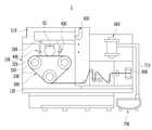
도 1은 와이어 쏘잉 장치의 잉곳 클램프의 일 형태를 보여주는 도면이다.1 is a view showing one form of an ingot clamp of a wire sawing device.
도 1에 도시된 바와 같이 잉곳 클램프(20)는 홀더 장착홈(21a)을 가지며 챔버의 상부 영역에 고정되는 클램프 본체(21)와, 홀더 장착홈(21a)에 끼워진 잉곳(IG)의 홀더(H)를 고정하기 위한 이동 고정부(22) 및 고정부(23)를 구비한다.As shown in FIG. 1, the
이동 고정부(22)는 다수개의 클램프 스프링(Clamp Spring)과 언클램프 실린더(Unclamp Cylinder)를 갖는다. 이동 고정부(22) 내부에는 클램프 스프링과 언클램프 스프링의 왕복 이동을 위한 내부 공간이 형성된다. 이동 고정부(22)의 외측에는 이러한 내부 공간을 덮는 덮개(22a)가 볼트(22b) 체결 등의 방법으로 결합된다.The moving
잉곳 클램프(20)의 홀더 장착홈(21a)에 잉곳(IG) 홀더(H)가 삽입되면, 잉곳 클램프(20)는 이동 고정부(22)의 클램프 스프링이 홀더(H)의 일측면을 가압하고, 고정부(23)는 홀더(H)의 타측면과 더욱 밀착되면서 고정이 이루어지는 방식으로 동작한다.When the ingot IG holder H is inserted into the
반대로 홀더(H)를 잉곳 클램프(20)에서 분리하기 위해서는 이동 고정부(22)의 언클램프 실린더가 동작하면서 홀더(H)를 가압하던 클램프 스프링을 반대방향으로 이동하여 가압을 해제한다.On the contrary, in order to separate the holder H from the
이와 같이 잉곳(IG)은 잉곳 클램프(20)에 홀더(H)가 클램프된 상태로 와이어를 향해 승하강하면서 슬라이싱 공정 작업을 수행할 수 있다. 슬라이싱 공정동안, 균일한 두께의 웨이퍼들을 얻기 위해서는 잉곳(IG)의 홀더(H)가 잉곳 클램프(20)에 안정적이고 균형있게 지지되어야 한다.In this way, the ingot IG may perform the slicing process while lifting and lowering toward the wire while the holder H is clamped to the
그런데, 상술한 바와 같이 잉곳 클램프(20)는 슬라이싱 공정동안 사용된 슬러리나 절단된 잉곳의 실리콘 입자 등 불순물이 이동 고정부(22)의 왕복 운동에 의한 압력 차이로 덮개(22a)의 틈을 통해 이동 고정부(22)의 내부 공간으로 침투함에 따라 내부 오염이 발생할 수 있다. 이러한 잉곳 클램프(20)의 내부 오염은 감압 등이 발생하여 잉곳(IG)의 홀더(H)에 대한 고정력을 약화시키거나 클램프 불균형을 야기하여 슬라이싱되는 웨이퍼 품질 저하로 이어지는 문제가 있다.However, as described above, the
또한, 잉곳 클램프(20)에서 이동 고정부(22)를 덮는 덮개(22a)는 밀봉력을 높이기 위해 실리콘 등의 마감처리를 하고 있는데 감압 등에 의해 내부 오염이 발생하게 되면 육안으로는 내부 오염 정도를 쉽게 확인하지 못하는 문제가 있다.In addition, the
본 발명은 슬라이싱 공정 동안 챔버 내에서 발생하는 잉곳의 파티클, 와이어의 메탈입자 등 불순물을 등에 의해 잉곳 클램프가 오염되는 것을 방지하여 잉곳의 고정력을 균일하게 유지함으로써 잉곳을 균형있고 안정적으로 지지하여 웨이퍼 품질 저하를 막을 수 있는 잉곳 클램프 및 그를 구비한 잉곳 절단용 와이어 쏘잉 장치를 제공하고자 한다.The present invention prevents the ingot clamp from being contaminated by impurities such as particles of ingots, metal particles of wires, etc. generated in the chamber during the slicing process, thereby maintaining the fixing force of the ingot uniformly, thereby supporting the ingot in a balanced and stable manner. It is an object of the present invention to provide an ingot clamp and an ingot cutting wire sawing device having the same.
본 발명은 홀더 장착홈과 캐비티를 갖는 클램프 본체; 상기 홀더 장착홈에 삽입된 잉곳 홀더의 일측을 지지하면서 고정하는 고정부; 상기 캐비티와 상기 홀더 장착홈에 배치되어 상기 잉곳 홀더의 타측을 가압하여 고정시키는 이동 고정부; 상기 클램프 본체에 결합되어 상기 캐비티를 덮는 커버 조립체; 및 상기 커버 조립체와 결합되어 상기 캐비티 내부로 에어를 공급하는 에어공급부; 를 포함하는 잉곳 클램프를 제공한다.The present invention provides a clamp body having a holder mounting groove and a cavity; A fixing part which supports and fixes one side of the ingot holder inserted into the holder mounting groove; A movement fixing part disposed in the cavity and the holder mounting groove to press and fix the other side of the ingot holder; A cover assembly coupled to the clamp body to cover the cavity; And an air supply unit coupled to the cover assembly to supply air into the cavity. It provides an ingot clamp comprising a.
상기 이동 고정부는 상기 홀더 장착홈을 통해 상기 클램프 본체에 결합되는 가압바; 상기 캐비티를 통해 상기 가압바와 고정되도록 장착되며 상기 가압바의 길이 방향을 따라 배치되는 다수의 클램프 스프링; 상기 캐비티를 통해 상기 다수의 클램프 스프링에 인접 배치되는 다수의 언클램프 실린더; 및 상기 다수의 클램프 스프링과 결합되어 상기 캐비티의 외측에 배치되는 지지바;를 포함할 수 있다.The moving fixing part is a pressure bar coupled to the clamp body through the holder mounting groove; A plurality of clamp springs mounted to be fixed to the pressure bar through the cavity and disposed along a length direction of the pressure bar; A plurality of unclamp cylinders disposed adjacent the plurality of clamp springs through the cavities; And a support bar coupled to the plurality of clamp springs and disposed outside the cavity.
상기 캐비티는 상기 클램프 본체의 측면을 따라 장공 형상으로 배치될 수 있다.The cavity may be disposed in the shape of a long hole along the side of the clamp body.
상기 커버 조립체는, 상기 지지바를 노출시키는 장공이 형성되며, 상기 클램프 본체에 결합되는 가스켓; 상기 지지바의 일부 영역을 노출시키는 장공이 형성되며, 상기 캐비티를 덮는 고정 커버; 및 상기 장공들을 통해 상기 캐비티 내부로 에어가 공급되도록 하며 상기 고정 커버를 덮는 에어공급 커버를 포함할 수 있다.The cover assembly may include a gasket having a long hole for exposing the support bar and coupled to the clamp body; A fixing cover which exposes a partial region of the support bar and covers the cavity; And an air supply cover for supplying air into the cavity through the holes and covering the fixed cover.
상기 커버 조립체는 상기 고정 커버의 장공 외측에 끼워지는 오링을 더 포함할 수 있다.The cover assembly may further include an O-ring fitted to the outside of the long hole of the fixed cover.
상기 클램프 본체는 상기 캐비티의 외주면을 따라 형성된 다수개의 볼트공을 더 포함할 수 있다.The clamp body may further include a plurality of bolt holes formed along the outer circumferential surface of the cavity.
상기 가스켓 및 상기 고정 커버는 각각 상기 다수개의 볼트공과 볼트 결합되도록 상기 다수개의 볼트공에 대응하는 다수의 체결공을 더 포함할 수 있다.The gasket and the fixing cover may further include a plurality of fastening holes corresponding to the plurality of bolt holes to be bolted to the plurality of bolt holes, respectively.
상기 에어공급 커버가 상기 고정 커버에 착탈결합되도록 상기 고정 커버 및 상기 에어공급 커버는 각각 볼트가 삽입되는 다수개의 결합공을 더 포함할 수 있다.The fixed cover and the air supply cover may further include a plurality of coupling holes into which the bolt is inserted so that the air supply cover is detachably coupled to the fixed cover.
상기 결합공들은 외측에 배치되고, 상기 체결공들은 내측에 배치될 수 있다.The coupling holes may be disposed outside, and the coupling holes may be disposed inside.
상기 에어공급 커버는 상기 에어공급부로부터 공급되는 에어가 유입되어 상기 캐비티 내부로 공급되도록 하는 에어유입부를 더 포함할 수 있다.The air supply cover may further include an air inlet unit through which air supplied from the air supply unit is introduced to be supplied into the cavity.
상기 에어유입부는 상기 에어공급부와 결합되는 에어유입홀; 상기 에어유입홀과 연통되며 상기 고정 커버의 장공 방향을 따라 길게 배치되는 에어유동유로; 및 상기 에어유동유로에 형성되며 상기 에어유동유로를 따라 유동하는 에어가 상기 장공들을 통과하여 상기 캐비티로 분사되도록 하는 다수의 분사홀을 포함할 수 있다.An air inlet hole coupled to the air supply unit; An air flow passage communicating with the air inlet hole and disposed to extend in the long hole direction of the fixed cover; And a plurality of injection holes formed in the air flow passage and allowing air flowing along the air flow passage to be injected into the cavity through the long holes.
상기 지지바는 상기 다수의 클램프 스프링이 장착되는 다수의 관통홀을 포함하며, 상기 에어유동유로는 상기 지지바의 관통홀에 대응되는 위치에 형성될 수 있다.The support bar may include a plurality of through holes in which the plurality of clamp springs are mounted, and the air flow passage may be formed at a position corresponding to the through holes of the support bar.
상기 에어공급부는 에어펌프; 및 일측이 상기 에어펌프와 결합되고 타측이 상기 에어유입홀과 결합되는 에어공급관을 포함할 수 있다.The air supply unit air pump; And an air supply pipe having one side coupled to the air pump and the other side coupled to the air inlet hole.
상기 에어공급관은 적어도 어느 구간이 용수철 형상을 가질 수 있다.At least any section of the air supply pipe may have a spring shape.
한편, 본 발명은 내측에 형성된 홀더 장착홈과, 측면을 따라 장공 형상으로 배치되는 캐비티를 갖는 클램프 본체; 상기 홀더 장착홈에 삽입된 잉곳 홀더의 일측을 지지하면서 고정하는 고정부; 상기 캐비티와 상기 홀더 장착홈에 배치되어 상기 잉곳 홀더의 타측을 가압하여 고정시키는 이동 고정부; 상기 클램프 본체에 결합되어 상기 캐비티를 일부 노출시키는 장공이 형성된 고정 커버; 상기 장공을 통해 상기 캐비티 내부로 에어가 공급되도록 하며 상기 고정 커버를 덮는 에어공급 커버; 및 상기 에어공급 커버와 결합되어 상기 캐비티 내부로 에어를 공급하는 에어공급부; 를 포함하는 잉곳 클램프를 제공한다.On the other hand, the present invention is a clamp body having a holder mounting groove formed in the inner side, and the cavity is arranged in a long hole shape along the side; A fixing part which supports and fixes one side of the ingot holder inserted into the holder mounting groove; A movement fixing part disposed in the cavity and the holder mounting groove to press and fix the other side of the ingot holder; A fixed cover coupled to the clamp body and having a long hole for partially exposing the cavity; An air supply cover for supplying air into the cavity through the long hole and covering the fixed cover; And an air supply unit coupled to the air supply cover to supply air into the cavity. It provides an ingot clamp comprising a.
상기 고정 커버와 상기 클램프 본체 사이에 결합되며 장공이 형성된 가스켓을 더 포함할 수 있다.The gasket may further include a gasket coupled between the fixing cover and the clamp body and having a long hole.
상기 고정 커버의 장공 외측에 끼워지는 오링을 더 포함할 수 있다.It may further include an O-ring fitted to the outside of the long hole of the fixed cover.
상기 에어공급 커버는 상기 에어공급부와 결합되는 에어유입홀; 상기 에어유입홀과 연통되며 상기 고정 커버의 장공 방향을 따라 길게 배치되는 에어유동유로; 및 상기 에어유동유로에 형성되며 상기 에어유동유로를 따라 유동하는 에어가 상기 장공들을 통과하여 상기 캐비티로 분사되도록 하는 다수의 분사홀을 포함할 수 있다.The air supply cover is an air inlet hole coupled with the air supply unit; An air flow passage communicating with the air inlet hole and disposed to extend in the long hole direction of the fixed cover; And a plurality of injection holes formed in the air flow passage and allowing air flowing along the air flow passage to be injected into the cavity through the long holes.
상기 에어공급부는 에어펌프; 및 일측이 상기 에어펌프와 결합되고 타측이 상기 에어유입홀과 결합되는 에어공급관을 포함할 수 있다.The air supply unit air pump; And an air supply pipe having one side coupled to the air pump and the other side coupled to the air inlet hole.
한편, 본 발명은 잉곳의 절단 작업이 이루어지는 챔버; 상기 챔버 내부에서 잉곳을 지지하는 상술한 잉곳 클램프 중 어느 하나의 잉곳 클램프; 상기 잉곳 클램프의 아래에서 슬러리를 분사하는 슬러리 분사 노즐; 상기 슬러리 분사 노즐 아래에 배치되며 상기 잉곳을 절단하는 복수의 와이어가 감겨진 메인 롤러;를 포함하는 와이어 쏘잉 장치를 제공한다.On the other hand, the present invention is a chamber in which the cutting operation of the ingot is made; Any one of the above-described ingot clamps for supporting the ingots in the chamber; A slurry spray nozzle for spraying a slurry under the ingot clamp; And a main roller disposed under the slurry spray nozzle and wound with a plurality of wires for cutting the ingot.
본 발명의 잉곳 클램프 및 그를 구비한 잉곳 절단용 와이어 쏘잉 장치에 따르면, 잉곳 클램프 내부에 양압을 유지함으로써 슬라이싱 공정 동안 챔버 내에서 발생하는 잉곳의 파티클, 와이어의 메탈입자 등 불순물을 등이 잉곳 클램프 내부 공간으로 침투하지 못하도록 함으로써 잉곳 클램프가 오염되는 것을 방지하여 잉곳의 고정력을 균일하게 유지함으로써 슬라이싱되는 웨이퍼의 품질을 향상시킬 수 있다.According to the ingot clamp and the ingot cutting wire sawing device having the same according to the present invention, by maintaining a positive pressure inside the ingot clamp inside the ingot clamp particles such as particles of the ingot generated in the chamber during the slicing process, metal particles of the wire, etc. By preventing penetration into the space, the ingot clamp can be prevented from being contaminated, thereby maintaining the holding force of the ingot uniformly, thereby improving the quality of the sliced wafer.
도 1은 와이어 쏘잉 장치의 잉곳 클램프의 일 형태를 보여주는 도면이다.
도 2는 일 실시예에 따른 와이어 쏘잉 장치의 구성도이다.
도 3은 도 2에 도시된 잉곳 클램프의 일 실시예에 따른 사시도이다.
도 4는 도 3의 분해 사시도이다.
도 5는 도 4의 주요부에 대한 확대도이다.
도 6은 도 5의 평면도이다.
도 7은 도 4의 커버 조립체의 확대도이다.
도 8은 도 7의 커버 조립체가 클램프 본체에 결합되는 상태를 보여준다.
도 9는 도 3의 정면도로서, 에어 공급을 보여주는 도면이다.
도 10은 도 9의 에어 공급 과정을 평면 상태에서 보여주는 도면이다.1 is a view showing one form of an ingot clamp of a wire sawing device.
2 is a block diagram of a wire sawing apparatus according to an embodiment.
3 is a perspective view according to one embodiment of the ingot clamp shown in FIG. 2.
4 is an exploded perspective view of FIG. 3.
5 is an enlarged view of a main part of FIG. 4.
6 is a plan view of FIG. 5.
7 is an enlarged view of the cover assembly of FIG. 4.
FIG. 8 shows a state in which the cover assembly of FIG. 7 is coupled to the clamp body.
FIG. 9 is a front view of FIG. 3 and shows an air supply. FIG.
10 is a view showing the air supply process of Figure 9 in a planar state.
이하, 실시 예들은 첨부된 도면 및 실시 예들에 대한 설명을 통하여 명백하게 드러나게 될 것이다. 실시 예의 설명에 있어서, 각 층(막), 영역, 패턴 또는 구조물들이 기판, 각 층(막), 영역, 패드 또는 패턴들의 "상/위(on)"에 또는 "하/아래(under)"에 형성되는 것으로 기재되는 경우에 있어, "상/위(on)"와 "하/아래(under)"는 "직접(directly)" 또는 "다른 층을 개재하여 (indirectly)" 형성되는 것을 모두 포함한다. 또한 각 층의 상/위 또는 하/아래에 대한 기준은 도면을 기준으로 설명한다.Hereinafter, the embodiments will be apparent from the accompanying drawings and the description of the embodiments. In the description of an embodiment, each layer (region), region, pattern, or structure is "on" or "under" the substrate, each layer (film), region, pad, or pattern. In the case where it is described as being formed at, "up" and "under" include both "directly" or "indirectly" formed through another layer. do. In addition, the criteria for up / down or down / down each layer will be described with reference to the drawings.
도면에서 크기는 설명의 편의 및 명확성을 위하여 과장되거나 생략되거나 또는 개략적으로 도시되었다. 또한 각 구성요소의 크기는 실제크기를 전적으로 반영하는 것은 아니다. 또한 동일한 참조번호는 도면의 설명을 통하여 동일한 요소를 나타낸다. 이하, 첨부된 도면을 참조하여 실시 예를 설명한다.In the drawings, sizes are exaggerated, omitted, or schematically illustrated for convenience and clarity of description. In addition, the size of each component does not necessarily reflect the actual size. Like reference numerals denote like elements throughout the description of the drawings. Hereinafter, exemplary embodiments will be described with reference to the accompanying drawings.
도 2는 일 실시예에 따른 와이어 쏘잉 장치의 구성도이다.2 is a block diagram of a wire sawing apparatus according to an embodiment.
도 2에 도시된 바와 같이, 일 형태의 와이어 쏘잉 장치(1)는 챔버(100, Chamber), 잉곳 클램프(200, Ingot Clamp), 쏘잉 유닛(300, Sawing Unit), 슬러리 공급 노즐(400, Slurry Suppling nozzle), 잉곳 피드 유닛(500, Ingot Feed Unit), 열교환기(600, Heat Exchanger), 슬러리 탱크(700, Slurry Tank) 등을 포함할 수 있다.As shown in FIG. 2, one type of
챔버(100)는 잉곳(IG)에 대한 절단, 즉 슬라이싱 작업이 이루어지는 공간을 이룬다. 예를 들어 챔버(100)는 직육면체 형상의 내부 공간을 갖는 룸(Room)일 수 있다. 챔버(100)에는 도어(미도시)가 장착되어, 잉곳(IG)을 투입하거나 슬라이싱된 웨이퍼를 꺼낼 때에는 챔버(100)는 개방되고 슬라이싱 작업시에는 챔버(100)는 폐쇄될 수 있다. 챔버(100)는 잉곳 클램프(200) 등이 장착되는 상부 챔버(110)와, 바닥면을 이루는 하부 챔버(120)를 포함할 수 있다.The
잉곳 클램프(200)는 챔버(100) 내부에서 잉곳(IG)을 지지한다. 잉곳 클램프(200)는 단결정 성장 잉곳(IG)의 상부를 클램프하여 하부 영역이 슬라이싱되는 동안 잉곳(IG)을 지지할 수 있다. 잉곳 클램프(200)는 잉곳(IG)이 탑재되므로 마운팅 블록(Mounting Block)이라 불리울 수 있다. 잉곳 클램프(200)의 상세한 구성은 후술하기로 한다.
쏘잉 유닛(300)은 잉곳(IG)을 다수개의 박판인 웨이퍼(Wafer)로 절단하며, 와이어 쏘우 방식을 이용하는 다양한 구성들을 포함할 수 있다. 예를 들어 쏘잉 유닛(300)은 스핀들(310, Spindle), 메인 롤러(320, Main Roller), 와이어(330, Wire)를 포함할 수 있다.The
스핀들(310)은 메인 롤러(320)의 축과 연결되며, 축을 중심으로 회전하면서 메인 롤러(320)를 회전시킬 수 있다. 예를 들어 스핀들(310)은 모터(미도시) 등의 구동 수단에 의해 고속 회전할 수 있다.The
메인 롤러(320)는 적어도 하나로 이루어질 수 있는데, 예를 들어 실시예처럼 3개, 즉 복수개로 이루어질 수 있다. 메인 롤러(320)는 후술할 와이어(330)의 이동을 가이드함으로 와이어 가이드 롤러(Wire Guide Roller)로 불리울 수 있다.The
메인 롤러(320)에는 와이어(330)가 감겨지는데, 메인 롤러(320)는 스핀들(310)의 회전에 따라 회전하므로 와이어(330)는 일 측의 보빈(800, Bobbin)에서부터 타측에 위치한 보빈(미도시)으로 이동하면서 메인 롤러(320) 상에서 고속으로 주행할 수 있다. 그리고 쏘잉 유닛(300)은 와이어(330)의 이동 경로를 변경시켜주기 위한 풀리(Pulley)들을 더 포함할 수 있다.The
와이어(330)는 메인 롤러(320)의 외주면에 일정 간격으로 다수개가 감겨질 수 있는데, 감겨진 와이어(330)의 간격에 의해 슬라이싱되는 웨이퍼의 개수 및 두께가 결정될 수 있다.A plurality of
슬러리 공급 노즐(400)은 와이어(330)로 슬러리 용액을 공급하기 위해 메인 롤러(320)의 상부에 배치될 수 있다. 슬러리 공급 노즐(400)로부터 분사되는 슬러리 용액들은 와이어(330)에 흡착되고, 슬러리 용액이 흡착된 와이어(330)에 의해 잉곳(IG)의 슬라이싱 작업이 이루어진다. 슬러리에는 연마 그레인이 포함되어 있기 때문에 잉곳(IG)이 와이어(330)를 향해 이동하여 가입되면, 와이어(330)에 묻어 있던 연마 그레인에 의해 잉곳(IG)이 절단될 수 있다.The
잉곳 피드 유닛(500)은 잉곳 클램프(200)를 메인 롤러(320)의 아래로 이동시켜 잉곳(IG)이 와이어(330)에 의해 슬라이싱되도록 하며, 잉곳(IG)이 웨이퍼로 슬라이싱된 후에는 잉곳 클램프(200)를 챔버(100)의 상부 영역으로 이동시킬 수 있다.The
열교환기(600)는 쏘잉 유닛(300)에 발생되는 열을 냉각시키는 역할을 하는데, 슬러리 분사 노즐(400)로 이동하는 슬러리의 온도를 실시간으로 조절할 수 있다. 따라서 열교환기(600)에 의하여 온도 조절된 슬러리가 와이어(330)에 분사되어 잉곳(IG)의 온도를 타겟(Target) 온도로 실시간으로 일정하게 유지시킬 수 있다.The
슬러리 탱크(700)는 슬러리를 저장하며, 슬러리 이송 라인(710)을 통해 슬러리를 이동시켜 슬러리 공급 노즐(400)을 통해 슬러리가 분사되도록 한다. 슬러리 탱크(700)는 내부에 수용된 슬러리 용액을 교반시키기 위한 교반부와, 교반부에 회전력을 전달하기 위한 교반기 구동부를 포함할 수 있다.The
슬라이싱 공정 중에 슬러리 용액 내에는 잉곳(IG)의 파티클이나 와이어(330)로부터 분리된 메탈 입자들이 포함되는데, 이러한 불순물이 포함된 슬러리는 챔버(100) 내부로 비산되면서 챔버(100) 내벽과 잉곳 클램프(200)에 내부에 침투하며 내부 공간을 오염시킬 수 있다. 이처럼 잉곳 클램프(200) 내부로 침투하는 불순물이 포함된 슬러리는 잉곳 클램프(200)의 고정력을 약화시켜 슬라이싱 공정에 악영향을 미칠 우려가 있다.During the slicing process, the slurry solution includes metal particles separated from particles or
이를 위해서 잉곳 클램프(200)의 내부 공간을 오염시키는 슬러리 불순물 등의 유입을 차단할 수 있어 잉곳 클램프(200)의 고정력을 균형있고 안정적으로 유지할 수 있는 잉곳 클램프(200)의 실시예에 따른 구성을 상술하기로 한다.To this end, it is possible to block the inflow of slurry impurities and the like contaminating the internal space of the
도 3은 도 2에 도시된 잉곳 클램프의 일 실시예에 따른 사시도이고, 도 4는 도 3의 분해 사시도이며, 도 5는 도 4의 주요부에 대한 확대도이고, 도 6은 도 5의 평면도이다.3 is a perspective view of an ingot clamp shown in FIG. 2, FIG. 4 is an exploded perspective view of FIG. 3, FIG. 5 is an enlarged view of an essential part of FIG. 4, and FIG. 6 is a plan view of FIG. 5. .
도 3 및 도 4에 도시된 바와 같이, 잉곳 클램프(200)는 클램프 본체(210), 고정부(230), 이동 고정부(220), 커버 조립체(240), 에어공급부(290)를 포함하여 구성될 수 있다.As shown in FIGS. 3 and 4, the
클램프 본체(210)는 홀더 장착홈(211)과 캐비티(213)를 가지며 챔버(100) 내부의 상부에 장착될 수 있다. 클램프 본체(210)는 블록 형상을 가지며, 잉곳(IG)의 길이에 상응하는 길이를 가질 수 있다. 클램프 본체(210)의 하부에는 하부홀(215)이 형성되어 일부가 개방된 형상으로 제작될 수 있고, 하부홀(215)이 막혀져 외부로부터 폐쇄될 수 있다.The
홀더 장착홈(211)은 클램프 본체(210)의 내측, 즉 클램프 본체(210)의 중심 영역 내부로부터 하측에 연장되도록 클램프 본체(210)에 관통 형성될 수 있다. 예를 들어 홀더 장착홈(211)은 도 4에 도시된 잉곳 홀더(H)의 형상에 대응하는 형상을 가질 수 있다. 잉곳 홀더(H)는 클램핑이 용이하도록 좌측면(D1)과 우측면(D2)에 경사면이 형성될 수 있다.The
캐비티(213)는 클램프 본체(210)의 측면을 따라 장공(Long hole) 형상으로 길게 배치될 수 있다. 예를 들어 캐비티(213)는 후술할 이동 고정부(220)가 장착되는 공간을 이루며, 클램프 본체(210)의 좌측면에 형성될 수 있다.The
고정부(230)는 홀더 장착홈(211)에 삽입된 잉곳 홀더(H)의 일측(D2)을 지지하면서 고정할 수 있다. 예를 들어 고정부(230)는 일정한 탄성을 갖는 패드(Pad)를 포함하여, 홀더 장착홈(211)의 일측(도면에서 우측)에 장착되어 잉곳 홀더(H)를 손상되지 않도록 지지할 수 있다.The fixing
이동 고정부(220)는 클램프 본체(210)의 캐비티(213)와 홀더 장착홈(211)에 배치되어 잉곳 홀더(H)의 타측(D1)을 가압하여 고정시킬 수 있다. 예를 들어 이동 고정부(220)는 도 5에 도시된 바와 같이 가압바(221), 클램프 스프링(222), 언클램프 실린더(223), 지지바(225)를 포함할 수 있다.The moving fixing
가압바(221)는 단면이 삼각형인 바 형상, 즉 프리즘(Prism) 형상을 가지며 홀더 장착홈(211) 내부에서 이동가능하게 설치될 수 있다. 이를 위해 가압바(221)는 홀더 장착홈(211)을 통해 클램프 본체(210)에 결합될 수 있다. 가압바(221)는 고정부(230)에 지지된 잉곳 홀더(H)의 타측면(D1)을 가압함으로써 잉곳 홀더(H)가 홀더 장착홈(211)에 밀착 고정되도록 할 수 있다.The
클램프 스프링(222)은 다수개로 이루어지며, 가압바(221)의 길이 방향을 따라 일정 간격 이격 배치될 수 있다. 본 실시예에서 클램프 스프링(222)은 4개를 도시하였으나 그 숫자는 변형실시 가능할 것이다. 예를 들어 클램프 스프링(222)은 다수개의 접시 스프링(Coned disk spring)과, 접시 스프링들의 내부를 관통하는 지지축을 포함할 수 있다.The
다수 개의 클램프 스프링(222)은 캐비티(213)를 통해 삽입되며, 홀더 장착홈(211)에 위치한 가압바(221)에 클램프 스프링(222)의 일측(예컨대 지지축의 일측)은 고정될 수 있다. 즉, 클램프 스프링(222)은 캐비티(213)를 통해 가압바(221)와 고정되도록 장착될 수 있다.The plurality of clamp springs 222 may be inserted through the
클램프 스프링(222)은 자체의 탄성에 의해 가압바(221)를 가압하면서 홀더 장착홈(211)에 삽입된 잉곳 홀더(H)를 가압하는 방식으로 동작할 수 있다.The
언클램프 실린더(223)는 다수개로 이루어지며, 캐비티(213)를 통해 다수의 클램프 스프링(222)에 인접 배치될 수 있다. 언클램프 실린더(223)는 유압펌프(미도시)로부터 유압오일을 제공받아서 캐비티(213) 내부에서 선형 운동을 할 수 있다. 언클램프 실린더(223)는 상술한 클램프 스프링(222)가 가압바(221)에 압력을 가하거나 압력을 해제하도록 동작시킬 수 있다. 즉, 언클램프 실린더(223)가 유압에 의해 동작하면 클램프 스프링(222)에 의해 가압바(221)에 가해진 압력을 해제하고, 유압을 제거하면 클램프 스프링(222)이 가압바(221)를 가압하도록 할 수 있다. 본 실시예에서 언클램프 실린더(223)는 3개를 도시하였으나 개수는 변형실시가능할 수 있다.The
지지바(225)는 다수의 클램프 스프링(222)과 결합되어 캐비티(213)의 외측에 배치될 수 있다. 지지바(225)에는 다수의 클램프 스프링(222)이 장착되는 다수의 관통홀(225c)이 형성될 수 있다. 예를 들어 지지바(225)에는 4개의 클램프 스프링(222)에 해당하는 4개의 관통홀(225c)이 형성될 수 있다. 관통홀(225c)에 삽입된 클램프 스프링(222)의 지지축은 너트(미도시)에 의해 지지바(225)에 고정될 수 있다.The
또한, 도 6에 도시된 바와 같이 클램프 스프링(222)과 지지바(225)의 사이에는 클램프 스프링(222)의 지지축이 삽입되는 통공이 형성된 고정 하우징(224)이 더 배치될 수 있다. 고정 하우징(224)은 클램프 스프링(222)의 개수에 대응하는 개수를 가질 수 있다. 고정 하우징(224)은 캐비티(213) 내부에서 클램프 스프링(222)의 위치를 안내하고, 언클램프 실린더(223)들 사이에서 언클램프 실린더(223)가 캐비티(213) 내부에서 안정적으로 지지되도록 하는 역할을 겸할 수 있다.In addition, as shown in FIG. 6, a fixing
상술한 구성을 갖는 이동 고정부(220)는 다음과 같이 동작할 수 있다.The
예를 들어 클램프 본체(210)의 홀더 장착홈(211)에 잉곳 홀더(H)가 삽입되면 이동 고정부(220)의 클램프 스프링(222)이 가압바(221)에 압력을 가해 잉곳 홀더(H)의 일측면(D1)을 가압하고, 고정부(230)는 잉곳 홀더(H)의 타측면(D2)과 더욱 밀착되면서 고정이 이루어지는 방식으로 동작한다.For example, when the ingot holder H is inserted into the
반대로 잉곳 홀더(H)를 홀더 장착홈(211)에서 분리하기 위해서는 이동 고정부(220)의 언클램프 실린더(223)가 유압에 의해 동작하면서 잉곳 홀더(H)를 가압하던 클램프 스프링(222)과 가압바(221)를 반대방향으로 이동하여 가압을 해제할 수 있다.On the contrary, in order to separate the ingot holder H from the
상술한 동작을 하는 이동 고정부(220)의 내부에는 캐비티(213)가 여전히 존재하여 외부로부터 이물질이 유입되어 오염이 발생할 여지가 있을 수 있다.The
이를 위해 클램프 본체(210)에는 캐비티(213)를 덮는 커버 조립체(240)가 결합될 수 있다.To this end, a
도 7은 도 4의 커버 조립체의 확대도이며, 도 8은 도 7의 커버 조립체가 클램프 본체에 결합되는 상태를 보여주고, 도 9는 도 3의 정면도로서, 에어 공급을 보여주는 도면이며, 도 10은 도 9의 에어 공급 과정을 평면 상태에서 보여주는 도면이다.7 is an enlarged view of the cover assembly of FIG. 4, FIG. 8 is a view illustrating a state in which the cover assembly of FIG. 7 is coupled to the clamp body, and FIG. 9 is a front view of FIG. 3, illustrating an air supply, and FIG. 10. 9 is a view showing the air supply process of FIG. 9 in a planar state.
도 7에 도시된 바와 같이 커버 조립체(240)는 가스켓(250), 고정 커버(260), 에어공급 커버(270)를 포함하여 클램프 본체(210)에 장착될 수 있다. 이를 위해 클램프 본체(210)에는 도 8에 도시된 바와 같이, 캐비티(213)가 형성된 측면에 다수개의 볼트공(211a)이 형성될 수 있다. 즉, 다수개의 볼트공(211a)은 캐비티(213)의 외주면을 따라 배열될 수 있다. 예를 들어 볼트공(211a)은 8개를 도시하였으나 그 개수는 변형 실시가능할 것이다.As shown in FIG. 7, the
가스켓(250)에는 상술한 이동 고정부(220)의 지지바(225)를 노출시키는 장공(251)이 형성되며, 클램프 본체(210)에 결합될 수 있다. 가스켓(250)은 클램프 본체(210)와 고정 커버(260)와의 사이를 밀폐시킴으로써 외부로부터 이물질이 유입되는 틈새를 막을 수 있다.The
가스켓(250)에는 클램프 본체(210)의 다수개의 볼트공(211a)과 볼트 결합되도록 다수개의 볼트공(211a)에 대응하는 다수의 체결공(253)이 형성될 수 있다.A plurality of
고정 커버(260)는 지지바(225)의 내측 영역을 노출시키는 장공(261)이 형성되며, 가스켓(250)과 결합되면서 캐비티(213)를 덮을 수 있다. 도 8에 도시된 바와 같이 지지바(225)는 캐비티(213)의 외측을 막는 형태이지만, 여전히 캐비티(213)의 일부 공간은 개방되어 있다.The fixing
따라서 고정 커버(260)의 장공(261)은 지지바(225)의 관통홀(225c)들을 노출시키며 지지바(225)와 밀착될 수 있다. 고정 커버(260)은 장공(261)은 가스켓(250)의 장공(251) 보다 크기가 작을 수 있다.Therefore, the
따라서 고정 커버(260)는 지지바(225)의 일부 영역을 노출시키는 장공(261)이 포함되지만 지지바(225)의 외측과 밀착될 수 있는 크기를 가지므로 캐비티(213)를 덮을 수 있다.Accordingly, the fixing
만약 캐비티(213) 내부로 이물질이 유입되었을 경우, 작업자는 후술할 에어공급 커버(270)를 고정 커버(260)로부터 분리한 후 캐비티(213) 내부로 이물질이 유입되었는지를 고정 커버(260)의 장공(261)을 통해 육안으로 확인할 수 있다.If foreign matter has flowed into the
고정 커버(260)는 장공(261) 외측에 끼워지는 오링(267, O-ring)을 더 포함할 수 있다. 오링(267)은 이동 고정부(220)의 지지바(225)와 접촉시 탄성을 제공할 뿐만 아니라 캐비티(213)와의 밀폐력을 향상시킬 수 있다.The fixed
고정 커버(260)는 가스켓(250)의 다수의 체결공(253) 및 클램프 본체(210)의 다수개의 볼트공(211a)과 볼트(미도시) 결합되도록 다수개의 볼트공(211a)에 대응하는 다수의 체결공(263)을 포함할 수 있다. 클램프 본체(210)에 장착된 고정 커버(260)에는 에어공급 커버(270)가 착탈 결합될 수 있다. 이를 위해 고정 커버(260)에는 볼트가 삽입되는 다수개의 결합공(265, 275)이 더 형성될 수 있다. 여기서 결합공(265, 275)들은 외측에 배치되고, 체결공(253, 263)들은 내측에 배치될 수 있다.The fixing
에어공급 커버(270)는 고정 커버(260)의 노출된 장공(261)을 덮어서 외부와의 밀폐력을 향상시키고, 전술한 가스켓(250)과 고정 커버(260)의 장공(251, 261)들을 통해 캐비티(213) 내부로 에어가 공급되도록 할 수 있다. 에어공급 커버(270)는 에어퍼지 커버 플레이트(Air Purge Cover Plate)로 불리울 수 있다.The
예를 들어 에어공급 커버(270)는 고정 커버(260) 보다 작은 크기를 가질 수 있다.For example, the
에어공급 커버(270)에는 고정 커버(260)에 착탈결합되도록 볼트(미도시)가 삽입되는 다수개의 결합공(275)이 형성될 수 있다.The
에어공급 커버(270)는 도 9 및 도 10에 도시된 바와 같이 후술할 에어공급부(290)로부터 공급되는 에어가 유입되어 상기 캐비티(213) 내부로 공급되도록 하는 에어유입부(280)를 더 포함할 수 있다.9 and 10, the
예를 들어 에어유입부(280)는 에어유입홀(281), 에어유동유로(282), 에어분사홀(283)을 포함하여 에어공급 커버(270)의 외측에 돌출된 형상으로 실시될 수 있다.For example, the
에어유입홀(281)은 에어공급부(290)와 결합되는 에어가 유입되는 통로를 형성할 수 있다. 예를 들어 에어유입홀(281)은 에어공급 커버(270)의 외측에 돌출된 형태로 이루어지는 수직 부재의 상부에 일정한 크기의 홀(hole)을 가공하여 실시될 수 있다.The
에어유동유로(282)는 에어유입홀(281)과 연통되며 고정 커버(260)의 장공(251, 261) 방향을 따라 길게 배치될 수 있다.The
에어분사홀(283)은 에어유동유로(282)에 다수개로 형성되며, 에어유동유로(282)를 따라 유동하는 에어가 상술한 장공(251, 261)들을 통과하여 캐비티(213)로 분사되도록 할 수 있다.A plurality of air injection holes 283 are formed in the
예를 들어 에어유동유로(282)는 지지바(225)의 관통홀(225c)에 대응되는 위치에 형성될 수 있다. 따라서 에어분사홀(283)은 지지바(225)의 관통홀(225c)을 통해 캐비티(213) 내부로 에어를 분사할 수 있다.For example, the
에어공급부(290)는 커버 조립체(240)와 결합되어 캐비티(213) 내부로 에어를 공급하여 캐비티(213) 내부를 양압(+ Pressure)으로 유지시킬 수 있다. 예를 들어 에어공급부(290)는 에어펌프(295), 에어공급관(291)을 포함할 수 있다.The
에어펌프(295)는 일정한 압력의 에어를 공급하며, 와이어 쏘잉 장치에서 챔버(100)의 일측에 장착될 수 있다. 에어펌프(295)에는 에어의 압력 조정을 위한 메뉴얼 밸브가 추가 설치되어 적정한 압력의 에어를 제공할 수 있다.The
에어공급관(291)은 일측이 에어펌프(295)와 결합되고 타측이 에어유입홀(281)과 결합되면서, 에어펌프(295)로부터 제공된 에어가 에어유입홀(281)을 통해 유입되도록 할 수 있다.The
여기서 에어공급관(291)은 적어도 어느 구간이 용수철(Spring) 형상을 가질 수 있다. 잘 알려진 바와 같이 용수철은 늘어나거나 줄어드는 탄력이 있는 나선형의 쇠줄을 의미한다.Here, the
에어공급관(291)이 용수철 형상을 갖게 되므로, 슬라이싱 공정동안 잉곳 홀더(H)가 승하강하면서 잉곳을 웨이퍼로 슬라이싱하더라도 에어공급관(291)은 길이가 유동적으로 변화하면서 공정에 영향을 미치지 않고 원활하게 에어를 공급할 수 있게 된다.Since the
이와 같이 본 발명의 잉곳 클램프 및 그를 구비한 잉곳 절단용 와이어 쏘잉 장치에 따르면, 잉곳 클램프 내부에 에어공급부를 통해 에어를 공급하여 캐비티 내부가 양압을 유지함으로써 슬라이싱 공정 동안 챔버 내에서 발생하는 잉곳의 파티클, 와이어의 메탈입자 등 불순물을 등이 잉곳 클램프 내부 공간으로 침투하지 못하도록 할 수 있다. 따라서 잉곳 클램프가 오염되는 것을 방지하여 잉곳의 고정력을 균일하게 유지함으로써 슬라이싱되는 웨이퍼의 품질을 향상시킬 수 있다.As described above, according to the ingot clamp and the ingot cutting wire sawing device having the same, the ingot particles are supplied in the air through the air supply unit to maintain the positive pressure inside the cavity, thereby generating particles of the ingot generated in the chamber during the slicing process. It is possible to prevent impurities such as metal particles of the wire from penetrating into the ingot clamp internal space. Therefore, the quality of the sliced wafer can be improved by preventing the ingot clamp from being contaminated and maintaining the holding force of the ingot uniformly.
또한, 에어공급부가 적정한 에어를 캐비티 내부로 공급하여 캐비티를 양압으로 유지하기 때문에 이물질의 유입되지 않으므로 캐비티를 덮는 커버 조립체는 실리콘 패킹 등의 번거로운 과정없이 볼트 등의 비교적 쉬운 체결 방식만으로 클램프 본체에 착탈결합되어 설치될 수 있다.In addition, since the air supply unit supplies proper air to the inside of the cavity to maintain the cavity at a positive pressure, foreign matter does not flow in, so that the cover assembly covering the cavity can be attached to or detached from the clamp body using a relatively easy fastening method such as a bolt without a cumbersome process such as silicone packing. Can be installed in combination.
나아가 에어공급 커버를 고정 커버로부터 분리한 후, 노출된 장공을 통해 캐비티 내부의 오염상태를 육안으로 확인할 수 있기 때문에 설령 캐비티 내부로 이물질이 유입되더라도 쉽고 빠르게 청소할 수 있게 된다.Furthermore, since the air supply cover is separated from the fixed cover, the state of contamination inside the cavity can be visually checked through the exposed long hole, so that even if foreign matters are introduced into the cavity, it can be easily and quickly cleaned.
이상에서 실시 예들에 설명된 특징, 구조, 효과 등은 본 발명의 적어도 하나의 실시 예에 포함되며, 반드시 하나의 실시 예에만 한정되는 것은 아니다. 나아가, 각 실시 예에서 예시된 특징, 구조, 효과 등은 실시 예들이 속하는 분야의 통상의 지식을 가지는 자에 의해 다른 실시 예들에 대해서도 조합 또는 변형되어 실시 가능하다. 따라서 이러한 조합과 변형에 관계된 내용들은 본 발명의 범위에 포함되는 것으로 해석되어야 할 것이다.Features, structures, effects, and the like described in the above embodiments are included in at least one embodiment of the present invention, and are not necessarily limited to only one embodiment. Furthermore, the features, structures, effects, and the like illustrated in the embodiments may be combined or modified with respect to other embodiments by those skilled in the art to which the embodiments belong. Therefore, contents related to such combinations and modifications should be construed as being included in the scope of the present invention.
1 : 와이어 쏘잉 장치100 : 챔버
110 : 상부 챔버120 : 하부 챔버
200 : 잉곳 클램프210 : 클램프 본체
211 : 홀더 장착홈211a : 볼트공
213 : 캐비티215 : 하부홀
220 : 이동 고정부221 : 가압바
222 : 클램프 스프링223 : 언클램프 실린더
224 : 고정 하우징225 : 지지바
240 : 커버 조립체250 : 가스켓
251 : 장공253 : 체결공
260 : 고정 커버261 : 장공
263 : 체결공265 : 결합공
267 : 오링270 : 에어공급 커버
273 : 볼트공275 : 결합공
280 : 에어유입부281 : 에어유입홀
282 : 에어유동유로283 : 에어분사홀
290 : 에어공급부291 : 에어공급관
295 : 에어펌프1: wire sawing device 100: chamber
110: upper chamber 120: lower chamber
200: ingot clamp 210: clamp body
211:
213: cavity 215: lower hole
220: moving fixing part 221: pressure bar
222: clamp spring 223: unclamp cylinder
224: fixed housing 225: support bar
240: cover assembly 250: gasket
251: long hole 253: fastener
260: fixed cover 261: long hole
263: fastening hole 265: coupling hole
267: O-ring 270: air supply cover
273: bolt hole 275: coupling hole
280: air inlet 281: air inlet hole
282: air flow path 283: air injection hole
290: air supply unit 291: air supply pipe
295: air pump
Claims (20)
Translated fromKorean상기 홀더 장착홈의 일측에 배치되어, 상기 홀더 장착홈에 삽입된 잉곳 홀더의 일측을 지지하면서 고정하는 고정부;
상기 캐비티와 상기 홀더 장착홈에 배치되어 상기 잉곳 홀더의 타측을 가압하여 고정시키는 이동 고정부;
상기 클램프 본체에 결합되어 상기 캐비티를 덮는 커버 조립체; 및
상기 커버 조립체와 결합되어 상기 캐비티 내부로 에어를 공급하는 에어공급부; 를 포함하는 잉곳 클램프.A clamp body having a holder mounting groove and a cavity;
A fixing part disposed at one side of the holder mounting groove to support and fix one side of the ingot holder inserted into the holder mounting groove;
A movement fixing part disposed in the cavity and the holder mounting groove to press and fix the other side of the ingot holder;
A cover assembly coupled to the clamp body to cover the cavity; And
An air supply unit coupled to the cover assembly to supply air into the cavity; Ingot clamp comprising a.
상기 이동 고정부는
상기 홀더 장착홈을 통해 상기 클램프 본체에 결합되는 가압바;
상기 캐비티를 통해 상기 가압바와 고정되도록 장착되며 상기 가압바의 길이 방향을 따라 배치되는 다수의 클램프 스프링;
상기 캐비티를 통해 상기 다수의 클램프 스프링에 인접 배치되는 다수의 언클램프 실린더; 및
상기 다수의 클램프 스프링과 결합되어 상기 캐비티의 외측에 배치되는 지지바;를 포함하는 잉곳 클램프.The method of claim 1,
The moving fixing part
A pressure bar coupled to the clamp body through the holder mounting groove;
A plurality of clamp springs mounted to be fixed to the pressure bar through the cavity and disposed along a length direction of the pressure bar;
A plurality of unclamp cylinders disposed adjacent the plurality of clamp springs through the cavities; And
And a support bar coupled to the plurality of clamp springs and disposed outside the cavity.
상기 캐비티는 상기 클램프 본체의 측면을 따라 장공 형상으로 배치되는 잉곳 클램프.The method of claim 2,
The cavity is ingot clamp disposed in the shape of a hole along the side of the clamp body.
상기 커버 조립체는,
상기 지지바를 노출시키는 장공이 형성되며, 상기 클램프 본체에 결합되는 가스켓;
상기 지지바의 일부 영역을 노출시키는 장공이 형성되며, 상기 가스켓과 결합되면서 상기 캐비티를 덮는 고정 커버; 및
상기 장공들을 통해 상기 캐비티 내부로 에어가 공급되도록 하며 상기 고정 커버를 덮는 에어공급 커버를 포함하는 잉곳 클램프.The method of claim 3,
The cover assembly,
A gasket for exposing the support bar and coupled to the clamp body;
A fixing cover having a long hole for exposing a portion of the support bar and coupled to the gasket to cover the cavity; And
And an air supply cover for supplying air into the cavity through the holes and covering the fixed cover.
상기 커버 조립체는 상기 고정 커버의 장공 외측에 끼워지는 오링을 더 포함하는 잉곳 클램프.The method of claim 4, wherein
The cover assembly further comprises an o-ring fitted to the outside of the long hole of the fixed cover.
상기 클램프 본체는 상기 캐비티의 외주면을 따라 형성된 다수개의 볼트공을 더 포함하는 잉곳 클램프.The method of claim 5,
The clamp body further comprises a plurality of bolt holes formed along the outer circumferential surface of the cavity.
상기 가스켓 및 상기 고정 커버는 각각 상기 다수개의 볼트공과 볼트 결합되도록 상기 다수개의 볼트공에 대응하는 다수의 체결공을 더 포함하는 잉곳 클램프.The method of claim 6,
The gasket and the fixing cover further comprises a plurality of fastening holes corresponding to the plurality of bolt holes to be bolted to the plurality of bolt holes, respectively.
상기 에어공급 커버가 상기 고정 커버에 착탈결합되도록 상기 고정 커버 및 상기 에어공급 커버는 각각 볼트가 삽입되는 다수개의 결합공을 더 포함하는 잉곳 클램프.The method of claim 7, wherein
The fixing cover and the air supply cover further comprises a plurality of coupling holes each bolt is inserted so that the air supply cover is detachably coupled to the fixed cover.
상기 에어공급 커버는 상기 에어공급부로부터 공급되는 에어가 유입되어 상기 캐비티 내부로 공급되도록 하는 에어유입부를 더 포함하는 잉곳 클램프.The method of claim 8,
The air supply cover further comprises an air inlet for allowing the air supplied from the air supply to be introduced into the cavity.
상기 에어유입부는
상기 에어공급부와 결합되는 에어유입홀;
상기 에어유입홀과 연통되며 상기 고정 커버의 장공 방향을 따라 길게 배치되는 에어유동유로; 및
상기 에어유동유로에 형성되며 상기 에어유동유로를 따라 유동하는 에어가 상기 장공들을 통과하여 상기 캐비티로 분사되도록 하는 다수의 분사홀을 포함하는 잉곳 클램프.The method of claim 10,
The air inlet portion
An air inlet hole coupled to the air supply unit;
An air flow passage communicating with the air inlet hole and disposed to extend in the long hole direction of the fixed cover; And
And a plurality of injection holes formed in the air flow passage and allowing air flowing along the air flow passage to be injected into the cavity through the long holes.
상기 지지바는 상기 다수의 클램프 스프링이 장착되는 다수의 관통홀을 포함하며,
상기 에어유동유로는 상기 지지바의 관통홀에 대응되는 위치에 형성되는 잉곳 클램프.The method of claim 11,
The support bar includes a plurality of through holes in which the plurality of clamp springs are mounted,
The inflow clamp is formed in a position corresponding to the through-hole of the support bar.
상기 에어공급부는
에어펌프; 및
일측이 상기 에어펌프와 결합되고 타측이 상기 에어유입홀과 결합되는 에어공급관을 포함하는 잉곳 클램프.The method of claim 12,
The air supply unit
Air pump; And
Ingot clamp comprising an air supply pipe one side is coupled to the air pump and the other side is coupled to the air inlet hole.
상기 에어공급관은 적어도 어느 구간이 용수철 형상을 갖는 잉곳 클램프.The method of claim 13,
The air supply pipe is ingot clamp having a spring shape at least any section.
상기 홀더 장착홈의 일측에 배치되어, 상기 홀더 장착홈에 삽입된 잉곳 홀더의 일측을 지지하면서 고정하는 고정부;
상기 캐비티와 상기 홀더 장착홈에 배치되어 상기 잉곳 홀더의 타측을 가압하여 고정시키는 이동 고정부;
상기 클램프 본체에 결합되어 상기 캐비티를 일부 노출시키는 장공이 형성된 고정 커버;
상기 장공을 통해 상기 캐비티 내부로 에어가 공급되도록 하며 상기 고정 커버를 덮는 에어공급 커버; 및
상기 에어공급 커버와 결합되어 상기 캐비티 내부로 에어를 공급하는 에어공급부; 를 포함하는 잉곳 클램프.A clamp body having a holder mounting groove formed in the inner side and a cavity disposed in a long hole shape along a side thereof;
A fixing part disposed at one side of the holder mounting groove to support and fix one side of the ingot holder inserted into the holder mounting groove;
A movement fixing part disposed in the cavity and the holder mounting groove to press and fix the other side of the ingot holder;
A fixed cover coupled to the clamp body and having a long hole for partially exposing the cavity;
An air supply cover for supplying air into the cavity through the long hole and covering the fixed cover; And
An air supply unit coupled to the air supply cover to supply air into the cavity; Ingot clamp comprising a.
상기 고정 커버와 상기 클램프 본체 사이에 결합되며 장공이 형성된 가스켓을 더 포함하는 잉곳 클램프.The method of claim 15,
Ingot clamp further comprises a gasket formed between the fixing cover and the clamp body, the long hole is formed.
상기 고정 커버의 장공 외측에 끼워지는 오링을 더 포함하는 잉곳 클램프.The method of claim 16,
Ingot clamp further comprises an O-ring fitted to the outside of the long hole of the fixed cover.
상기 에어공급 커버는
상기 에어공급부와 결합되는 에어유입홀;
상기 에어유입홀과 연통되며 상기 고정 커버의 장공 방향을 따라 길게 배치되는 에어유동유로; 및
상기 에어유동유로에 형성되며 상기 에어유동유로를 따라 유동하는 에어가 상기 캐비티로 분사되도록 하는 다수의 분사홀을 포함하는 잉곳 클램프.The method of claim 17,
The air supply cover
An air inlet hole coupled to the air supply unit;
An air flow passage communicating with the air inlet hole and disposed to extend in the long hole direction of the fixed cover; And
And an ingot clamp formed in the air flow passage and including a plurality of injection holes to allow air flowing along the air flow passage to be injected into the cavity.
상기 에어공급부는
에어펌프; 및
일측이 상기 에어펌프와 결합되고 타측이 상기 에어유입홀과 결합되는 에어공급관을 포함하는 잉곳 클램프.The method of claim 18,
The air supply unit
Air pump; And
Ingot clamp comprising an air supply pipe one side is coupled to the air pump and the other side is coupled to the air inlet hole.
상기 챔버 내부에서 잉곳을 지지하는 청구항 제1항 내지 제8항, 제10항 내지 제19항 중 어느 한 항에 기재된 잉곳 클램프;
상기 잉곳 클램프의 아래에서 슬러리를 분사하는 슬러리 분사 노즐; 및
상기 슬러리 분사 노즐 아래에 배치되며 상기 잉곳을 절단하는 복수의 와이어가 감겨진 메인 롤러;를 포함하는 와이어 쏘잉 장치.A chamber in which the cutting operation of the ingot is made;
Ingot clamp according to any one of claims 1 to 8, 10 to 19 for supporting the ingot inside the chamber;
A slurry spray nozzle for spraying a slurry under the ingot clamp; And
And a main roller disposed under the slurry spray nozzle and wound with a plurality of wires for cutting the ingot.
Priority Applications (5)
| Application Number | Priority Date | Filing Date | Title |
|---|---|---|---|
| KR1020170171904AKR102037745B1 (en) | 2017-12-14 | 2017-12-14 | Ingot clamping device and wire sawing apparatus for cutting Ingot having the same |
| US15/902,292US10882214B2 (en) | 2017-12-14 | 2018-02-22 | Ingot clamping device and wire sawing apparatus for slicing ingot having the same |
| JP2018031594AJP6546303B2 (en) | 2017-12-14 | 2018-02-26 | Ingot clamp and wire sawing apparatus for ingot cutting comprising the same |
| DE102018203741.8ADE102018203741B4 (en) | 2017-12-14 | 2018-03-13 | Block chuck and wire sawing device for slicing the block that it has |
| CN201810360709.0ACN109955398B (en) | 2017-12-14 | 2018-04-20 | Ingot holding device and wire saw apparatus for slicing ingot having the same |
Applications Claiming Priority (1)
| Application Number | Priority Date | Filing Date | Title |
|---|---|---|---|
| KR1020170171904AKR102037745B1 (en) | 2017-12-14 | 2017-12-14 | Ingot clamping device and wire sawing apparatus for cutting Ingot having the same |
Publications (2)
| Publication Number | Publication Date |
|---|---|
| KR20190071139A KR20190071139A (en) | 2019-06-24 |
| KR102037745B1true KR102037745B1 (en) | 2019-10-29 |
Family
ID=66675020
Family Applications (1)
| Application Number | Title | Priority Date | Filing Date |
|---|---|---|---|
| KR1020170171904AActiveKR102037745B1 (en) | 2017-12-14 | 2017-12-14 | Ingot clamping device and wire sawing apparatus for cutting Ingot having the same |
Country Status (5)
| Country | Link |
|---|---|
| US (1) | US10882214B2 (en) |
| JP (1) | JP6546303B2 (en) |
| KR (1) | KR102037745B1 (en) |
| CN (1) | CN109955398B (en) |
| DE (1) | DE102018203741B4 (en) |
Families Citing this family (9)
| Publication number | Priority date | Publication date | Assignee | Title |
|---|---|---|---|---|
| CN110202709A (en)* | 2019-07-09 | 2019-09-06 | 深圳市雯逸水晶有限公司 | A kind of adjustable cutting washing degumming device of single crystal product article |
| CN112536477B (en)* | 2020-11-12 | 2022-10-28 | 浙江工业大学 | Electrostatic spray diamond wire saw cutting machine with saw wire cleaning device |
| CN114227499B (en)* | 2021-12-18 | 2024-03-08 | 浙江大学湖州研究院 | Water treatment membrane element buddha's warrior attendant line cutting equipment |
| CN115263424A (en)* | 2022-08-24 | 2022-11-01 | 国网山东省电力公司枣庄供电公司 | A tunnel cable installation device |
| CN115609774A (en)* | 2022-09-30 | 2023-01-17 | 青岛高测科技股份有限公司 | Crystal support clamping device, feeding mechanism, wire cutting machine, detection system and method |
| CN218902847U (en)* | 2022-11-16 | 2023-04-25 | 天津市环欧新能源技术有限公司 | An off-line spray cleaning device for a wire cutter |
| CN116540503B (en)* | 2023-07-03 | 2023-10-24 | 之江实验室 | A fixing device and working method for laser direct writing samples |
| CN116945010A (en)* | 2023-09-21 | 2023-10-27 | 长治高测新材料科技有限公司 | Clamping assembly, feeding mechanism and wire cutting device |
| CN119658572B (en)* | 2025-02-14 | 2025-05-09 | 温州市华海密封件有限公司 | Production equipment for metal sealing ring gasket for oil and gas pipeline installation |
Citations (4)
| Publication number | Priority date | Publication date | Assignee | Title |
|---|---|---|---|---|
| KR100269964B1 (en) | 1994-05-19 | 2000-11-01 | 오쯔보 히데오 | Work piece position decision method and its apparatus |
| JP2003534939A (en) | 2000-05-31 | 2003-11-25 | エムイーエムシー・エレクトロニック・マテリアルズ・ソシエタ・ペル・アチオニ | Wire saw and process for slicing a plurality of semiconductor ingots |
| JP2015512792A (en) | 2012-02-28 | 2015-04-30 | マイヤー ブルガー アーゲー | Holding device |
| JP2015122424A (en) | 2013-12-24 | 2015-07-02 | 信越半導体株式会社 | Work cutting method and work holding jig |
Family Cites Families (19)
| Publication number | Priority date | Publication date | Assignee | Title |
|---|---|---|---|---|
| US3831576A (en) | 1971-11-22 | 1974-08-27 | Motorola Inc | Machine and method for cutting brittle materials using a reciprocating cutting wire |
| JPS61168466A (en) | 1985-01-21 | 1986-07-30 | Yasunaga Eng Kk | Faint pushup device of work |
| US5060920A (en)* | 1990-12-20 | 1991-10-29 | Eddy Engibarov | Quick change jaw assembly for high precision machining |
| JP2768398B2 (en)* | 1994-05-19 | 1998-06-25 | 株式会社東京精密 | Method and apparatus for aligning crystal orientation when cutting single crystal material |
| JPH0864542A (en) | 1994-08-25 | 1996-03-08 | Plasma Syst:Kk | Vacuum chamber for semiconductor processing apparatus and method of manufacturing the same |
| JPH09248822A (en) | 1996-03-18 | 1997-09-22 | Tokyo Seimitsu Co Ltd | Detecting structure for guide roller abrasion of wire saw |
| JP3137600B2 (en) | 1997-09-12 | 2001-02-26 | 株式会社日平トヤマ | Workpiece crystal orientation adjustment method |
| JPH11147218A (en) | 1997-11-17 | 1999-06-02 | Nippei Toyama Corp | Wire saw |
| US6557443B1 (en)* | 1999-09-09 | 2003-05-06 | Larue Mark C. | Bar feeder for machining center |
| JP2002120139A (en) | 2000-10-13 | 2002-04-23 | Nippei Toyama Corp | Work supporting device and wire saw using it |
| JP3975778B2 (en) | 2002-02-28 | 2007-09-12 | 日本精工株式会社 | Work processing equipment |
| KR20100092776A (en)* | 2009-02-13 | 2010-08-23 | 주식회사 실트론 | Mounting block for holding ingot |
| CN201760976U (en) | 2010-07-16 | 2011-03-16 | 新余市银龙机电科技有限公司 | Machine seat for four-roller guide wheel |
| CN202079686U (en) | 2011-05-12 | 2011-12-21 | 无锡机床股份有限公司 | Workpiece clamping mechanism of multi-wire cutting machine |
| KR101279388B1 (en)* | 2011-08-16 | 2013-07-04 | 주식회사 엘지실트론 | Apparatus for fixing ingot |
| EP2826582B1 (en) | 2013-07-17 | 2016-04-06 | Applied Materials Switzerland Sàrl | Wire saw device and method of manufacturing thereof |
| JP5948569B2 (en) | 2013-11-05 | 2016-07-06 | パナソニックIpマネジメント株式会社 | Slicing device |
| JP2017148872A (en) | 2016-02-22 | 2017-08-31 | 株式会社東振テクニカル | Work rest structure, work rest, and centerless grinder |
| US10882148B2 (en)* | 2017-08-01 | 2021-01-05 | Caromation, Inc. | Pivot unit |
- 2017
- 2017-12-14KRKR1020170171904Apatent/KR102037745B1/enactiveActive
- 2018
- 2018-02-22USUS15/902,292patent/US10882214B2/enactiveActive
- 2018-02-26JPJP2018031594Apatent/JP6546303B2/enactiveActive
- 2018-03-13DEDE102018203741.8Apatent/DE102018203741B4/enactiveActive
- 2018-04-20CNCN201810360709.0Apatent/CN109955398B/enactiveActive
Patent Citations (4)
| Publication number | Priority date | Publication date | Assignee | Title |
|---|---|---|---|---|
| KR100269964B1 (en) | 1994-05-19 | 2000-11-01 | 오쯔보 히데오 | Work piece position decision method and its apparatus |
| JP2003534939A (en) | 2000-05-31 | 2003-11-25 | エムイーエムシー・エレクトロニック・マテリアルズ・ソシエタ・ペル・アチオニ | Wire saw and process for slicing a plurality of semiconductor ingots |
| JP2015512792A (en) | 2012-02-28 | 2015-04-30 | マイヤー ブルガー アーゲー | Holding device |
| JP2015122424A (en) | 2013-12-24 | 2015-07-02 | 信越半導体株式会社 | Work cutting method and work holding jig |
Also Published As
| Publication number | Publication date |
|---|---|
| US20190184603A1 (en) | 2019-06-20 |
| DE102018203741A1 (en) | 2019-06-19 |
| JP2019106518A (en) | 2019-06-27 |
| CN109955398A (en) | 2019-07-02 |
| DE102018203741B4 (en) | 2020-06-18 |
| US10882214B2 (en) | 2021-01-05 |
| CN109955398B (en) | 2021-01-12 |
| JP6546303B2 (en) | 2019-07-17 |
| KR20190071139A (en) | 2019-06-24 |
Similar Documents
| Publication | Publication Date | Title |
|---|---|---|
| KR102037745B1 (en) | Ingot clamping device and wire sawing apparatus for cutting Ingot having the same | |
| US4738056A (en) | Method and blasting apparatus for preparation of silicon wafer | |
| CN109421185B (en) | Cutting method and cutting device for crystal bar | |
| US8230847B2 (en) | Mounting plate for a wire sawing device, wire sawing device comprising the same, and wire sawing process carried out by the device | |
| KR101005245B1 (en) | Semiconductor Wafer Grinding | |
| TW201309450A (en) | Cutting machine and cutting method | |
| JPH11198020A (en) | Fixed abrasive grain wire saw | |
| US5918587A (en) | Method of producing slices | |
| KR101079468B1 (en) | Carrier for double side polishing apparatus and double side polishing method using the same | |
| KR101303552B1 (en) | Method for chemically grinding a semiconductor wafer on both sides | |
| JPH09216223A (en) | Fretsaw pulling device | |
| KR101951736B1 (en) | Wire Sawing Apparatus For Cutting Single Crystal Ingot | |
| KR102282063B1 (en) | Ingot temperature controller and Wire sawing apparatus having the same | |
| KR20230162540A (en) | Method of grinding wafer and apparatus of grinding wafer | |
| KR102448143B1 (en) | wire sawing device | |
| KR101540568B1 (en) | A wire sawing apparatus and method | |
| KR20210097333A (en) | Wire sawing apparatus | |
| JP7733486B2 (en) | Nozzle adjustment jig | |
| JP3663705B2 (en) | Semiconductor wafer polishing equipment | |
| KR102116510B1 (en) | Wafer Lapping Apparatus | |
| KR20130074192A (en) | Wire cleaning unit and wire saw apparatus including the same | |
| KR20200006386A (en) | Wire saw align unit and wire sawing apparatus having the same and align method using it | |
| KR20200088676A (en) | Ingot Clamp and Wire sawing apparatus having the same | |
| KR101596734B1 (en) | Variable wire-saw device | |
| KR20160128112A (en) | Pulley, the manufacturing method thereof and wire saw apparatus having the same |
Legal Events
| Date | Code | Title | Description |
|---|---|---|---|
| A201 | Request for examination | ||
| PA0109 | Patent application | Patent event code:PA01091R01D Comment text:Patent Application Patent event date:20171214 | |
| PA0201 | Request for examination | ||
| E902 | Notification of reason for refusal | ||
| PE0902 | Notice of grounds for rejection | Comment text:Notification of reason for refusal Patent event date:20190417 Patent event code:PE09021S01D | |
| PG1501 | Laying open of application | ||
| E701 | Decision to grant or registration of patent right | ||
| PE0701 | Decision of registration | Patent event code:PE07011S01D Comment text:Decision to Grant Registration Patent event date:20191007 | |
| GRNT | Written decision to grant | ||
| PR0701 | Registration of establishment | Comment text:Registration of Establishment Patent event date:20191023 Patent event code:PR07011E01D | |
| PR1002 | Payment of registration fee | Payment date:20191024 End annual number:3 Start annual number:1 | |
| PG1601 | Publication of registration | ||
| PR1001 | Payment of annual fee | Payment date:20220922 Start annual number:4 End annual number:4 | |
| PR1001 | Payment of annual fee | Payment date:20240919 Start annual number:6 End annual number:6 |