KR102032878B1 - Method for correcting error of flash storage controller - Google Patents
Method for correcting error of flash storage controllerDownload PDFInfo
- Publication number
- KR102032878B1 KR102032878B1KR1020170178505AKR20170178505AKR102032878B1KR 102032878 B1KR102032878 B1KR 102032878B1KR 1020170178505 AKR1020170178505 AKR 1020170178505AKR 20170178505 AKR20170178505 AKR 20170178505AKR 102032878 B1KR102032878 B1KR 102032878B1
- Authority
- KR
- South Korea
- Prior art keywords
- stripe
- ecc
- flash memory
- data
- parity
- Prior art date
- Legal status (The legal status is an assumption and is not a legal conclusion. Google has not performed a legal analysis and makes no representation as to the accuracy of the status listed.)
- Expired - Fee Related
Links
Images


Classifications
- G—PHYSICS
- G06—COMPUTING OR CALCULATING; COUNTING
- G06F—ELECTRIC DIGITAL DATA PROCESSING
- G06F11/00—Error detection; Error correction; Monitoring
- G06F11/07—Responding to the occurrence of a fault, e.g. fault tolerance
- G06F11/0703—Error or fault processing not based on redundancy, i.e. by taking additional measures to deal with the error or fault not making use of redundancy in operation, in hardware, or in data representation
- G06F11/0706—Error or fault processing not based on redundancy, i.e. by taking additional measures to deal with the error or fault not making use of redundancy in operation, in hardware, or in data representation the processing taking place on a specific hardware platform or in a specific software environment
- G06F11/073—Error or fault processing not based on redundancy, i.e. by taking additional measures to deal with the error or fault not making use of redundancy in operation, in hardware, or in data representation the processing taking place on a specific hardware platform or in a specific software environment in a memory management context, e.g. virtual memory or cache management
- G—PHYSICS
- G06—COMPUTING OR CALCULATING; COUNTING
- G06F—ELECTRIC DIGITAL DATA PROCESSING
- G06F11/00—Error detection; Error correction; Monitoring
- G06F11/07—Responding to the occurrence of a fault, e.g. fault tolerance
- G06F11/08—Error detection or correction by redundancy in data representation, e.g. by using checking codes
- G06F11/10—Adding special bits or symbols to the coded information, e.g. parity check, casting out 9's or 11's
- G06F11/1008—Adding special bits or symbols to the coded information, e.g. parity check, casting out 9's or 11's in individual solid state devices
- G—PHYSICS
- G06—COMPUTING OR CALCULATING; COUNTING
- G06F—ELECTRIC DIGITAL DATA PROCESSING
- G06F11/00—Error detection; Error correction; Monitoring
- G06F11/07—Responding to the occurrence of a fault, e.g. fault tolerance
- G06F11/08—Error detection or correction by redundancy in data representation, e.g. by using checking codes
- G06F11/10—Adding special bits or symbols to the coded information, e.g. parity check, casting out 9's or 11's
- G06F11/1076—Parity data used in redundant arrays of independent storages, e.g. in RAID systems
- G—PHYSICS
- G06—COMPUTING OR CALCULATING; COUNTING
- G06F—ELECTRIC DIGITAL DATA PROCESSING
- G06F2211/00—Indexing scheme relating to details of data-processing equipment not covered by groups G06F3/00 - G06F13/00
- G06F2211/10—Indexing scheme relating to G06F11/10
- G06F2211/1002—Indexing scheme relating to G06F11/1076
- G06F2211/1014—Compression, i.e. RAID systems with parity using compression techniques
- G—PHYSICS
- G06—COMPUTING OR CALCULATING; COUNTING
- G06F—ELECTRIC DIGITAL DATA PROCESSING
- G06F2211/00—Indexing scheme relating to details of data-processing equipment not covered by groups G06F3/00 - G06F13/00
- G06F2211/10—Indexing scheme relating to G06F11/10
- G06F2211/1002—Indexing scheme relating to G06F11/1076
- G06F2211/1028—Distributed, i.e. distributed RAID systems with parity
- G—PHYSICS
- G06—COMPUTING OR CALCULATING; COUNTING
- G06F—ELECTRIC DIGITAL DATA PROCESSING
- G06F2211/00—Indexing scheme relating to details of data-processing equipment not covered by groups G06F3/00 - G06F13/00
- G06F2211/10—Indexing scheme relating to G06F11/10
- G06F2211/1002—Indexing scheme relating to G06F11/1076
- G06F2211/109—Sector level checksum or ECC, i.e. sector or stripe level checksum or ECC in addition to the RAID parity calculation
Landscapes
- Engineering & Computer Science (AREA)
- Theoretical Computer Science (AREA)
- Quality & Reliability (AREA)
- Physics & Mathematics (AREA)
- General Engineering & Computer Science (AREA)
- General Physics & Mathematics (AREA)
- Techniques For Improving Reliability Of Storages (AREA)
Abstract
Translated fromKoreanDescription
Translated fromKorean본 발명은 플래시 메모리 컨트롤러의 에러 정정 방법에 관한 것으로서, 더욱 상세하게는, 압축 데이터를 페이지의 다른 위치에 배치되고 사용하지 아니한 영역을 패리티 클러스터 내에 분산 배치되고 적응적으로 조정된 ECC의 소스 길이로 인해 인코딩되므로 되므로, 패리티 오버 헤드를 줄일 수 있고, 동일한 RAID 신뢰도 레벨에서 쓰기 증폭 요소를 감소할 수 있으며, 추가 ECC 오버 헤드 없이 ECC에 대한 신뢰도를 향상시킬 수 있는 기술에 관한 것이다. 본 발명은 플래시 메모리 컨트롤러의 에러 정정 방법에 관한 것으로서, 더욱 상세하게는, 압축 데이터를 페이지의 다른 위치에 배치되고 사용하지 아니한 영역을 패리티 클러스터 내에 분산 배치되고 적응적으로 조정된 ECC의 소스 길이로 인해 인코딩되므로 되므로, 패리티 오버 헤드를 줄일 수 있고, 동일한 RAID 신뢰도 레벨에서 쓰기 증폭 요소를 감소할 수 있으며, 추가 ECC 오버 헤드 없이 ECC에 대한 신뢰도를 향상시킬 수 있는 기술에 관한 것이다.The present invention relates to an error correction method of a flash memory controller, and more particularly, to a source length of an ECC distributedly arranged and adaptively adjusted in a parity cluster, in which regions of compressed data are arranged and not used at different positions of a page. As a result, the present invention relates to a technique that can reduce parity overhead, reduce write amplification factor at the same RAID reliability level, and improve reliability of ECC without additional ECC overhead. The present invention relates to an error correction method of a flash memory controller, and more particularly, to a source length of an ECC distributedly arranged and adaptively adjusted in a parity cluster, in which regions of compressed data are arranged and not used at different positions of a page. As a result, the present invention relates to a technique that can reduce parity overhead, reduce write amplification factor at the same RAID reliability level, and improve reliability of ECC without additional ECC overhead.
최근 컴퓨터 환경에 대한 패러다임(paradigm)이 언제, 어디서나 컴퓨팅 시스템을 사용할 수 있도록 하는 유비쿼터스 컴퓨팅(ubiquitous computing)으로 전환되고 있다. 이로 인해 휴대폰, PMP, 디지털 카메라, 노트북 컴퓨터 등과 같은 휴대용 전자 장치의 사용이 급증하고 있다. 이와 같은 휴대용 전자 장치는 일반적으로 하드 디스크 드라이브 대신 메모리 장치를 이용하는 데이터 저장 장치를 사용한다.Recently, the paradigm of computing environment has been shifted to ubiquitous computing, which enables computing systems to be used anytime and anywhere. As a result, the use of portable electronic devices such as mobile phones, PMPs, digital cameras, notebook computers, and the like is increasing rapidly. Such portable electronic devices generally use data storage devices that use memory devices instead of hard disk drives.
메모리 장치를 이용한 데이터 저장 장치 중 하나인 솔리드 스테이트 드라이브(solid state drive, 이하, SSD라고 칭함)는 저장 매체가 모두 메모리 장치로 구성된 데이터 저장 장치이다. SSD는 기존의 데이터 저장 장치에서 사용되고 있는 PATA나 SATA 등의 호스트 인터페이스를 이용하여 하드 디스크 드라이브처럼 사용될 수 있다. SSD는 기계적인 구동부가 없고 기존의 하드 디스크 드라이브에 비해 안정성 및 내구성이 뛰어나며 정보의 액세스 속도가 매우 빠르고 전력 소모가 적다는 장점이 있다.One of the data storage devices using a memory device, a solid state drive (hereinafter, referred to as SSD), is a data storage device in which storage media are all composed of memory devices. SSDs can be used like hard disk drives using host interfaces such as PATA and SATA, which are used in traditional data storage devices. SSDs do not have mechanical drives and are more reliable and durable than traditional hard disk drives, and provide fast access to information and low power consumption.
이러한 SSD에서 낸드 플래시 저장 매체를 사용하는 경우 오류 정정을 위해 ECC가 통합되어 있으나, 과도한 증가 오류를 복귀하는데 한계가 있으며 이를 보완하기 위해 RAID 등의 신뢰도가 높은 재저장 장치를 제안하고 있으나, 패리티 오버 헤드를 가지므로 쓰기 증폭이 증가되어 수명이 단축되는 단점이 있었다.When NAND flash storage media is used in such SSDs, ECC is integrated for error correction, but there is a limit to returning excessive incremental errors, and to compensate for this, a highly reliable restorage device such as RAID is proposed, but parity over Because of the head, the write amplification is increased to shorten the lifespan.
이에 본 출원인은 압축 데이터를 페이지의 다른 위치에 배치되고 사용하지 아니한 영역을 패리티 클러스터 내에 분산 배치되므로, 패리티 오버 헤드를 줄일 수 있고, 동일한 RAID 신뢰도 레벨에서 쓰기 증폭 요소를 감소할 수 있으며, 적응적으로 조정된 ECC의 소스 길이로 인해 인코딩되므로 추가 ECC 오버 헤드 없이 ECC에 대한 신뢰도를 향상시킬 수 있는 방안을 제안하고자 한다.As a result, the present inventors distribute compressed data in different positions of the page and distribute unused regions in the parity cluster, thereby reducing parity overhead, and reducing write amplification factor at the same RAID reliability level. Since the encoding is due to the adjusted source length of the ECC, we propose a method to improve the reliability of the ECC without additional ECC overhead.
본 발명은 압축 데이터를 페이지의 다른 위치에 배치되고 사용하지 아니한 영역을 패리티 클러스터 내에 분산 배치되므로, 패리티 오버 헤드를 줄일 수 있고, 동일한 RAID 신뢰도 레벨에서 쓰기 증폭 요소를 감소할 수 있는 플래시 메모리 컨트롤러의 오류 정정 방법을 제공하고자 함에 그 목적이 있다.According to the present invention, since the compressed data is disposed at different positions of the page and unused areas are distributed in the parity cluster, parity overhead can be reduced and write amplification factor can be reduced at the same RAID reliability level. The purpose is to provide an error correction method.
또한 본 발명의 다른 목적은 적응적으로 조정된 ECC의 소스 길이로 인해 인코딩되므로 추가 ECC 오버 헤드 없이 ECC에 대한 신뢰도를 향상시킬 수 있는 플래시 메모리 컨트롤러의 오류 정정 방법을 제공하고자 함에 있다.In addition, another object of the present invention is to provide an error correction method of a flash memory controller that can be encoded due to the adaptively adjusted ECC source length, thereby improving the reliability of the ECC without additional ECC overhead.
본 발명의 목적은 이상에서 언급한 목적으로 제한되지 않으며, 언급되지 않은 본 발명의 다른 목적 및 장점들은 하기의 설명에 의해서 이해될 수 있으며, 본 발명의 실시예에 의해 보다 분명하게 알게 될 것이다. 또한, 본 발명의 목적 및 장점들은 특허청구 범위에 나타낸 수단 및 그 조합에 의해 실현될 수 있음을 쉽게 알 수 있을 것이다.The object of the present invention is not limited to the above-mentioned object, other objects and advantages of the present invention not mentioned can be understood by the following description, will be more clearly understood by the embodiments of the present invention. It will also be readily apparent that the objects and advantages of the invention may be realized by the means and combinations thereof indicated in the claims.
전술한 목적을 달성하기 위한 본 발명의 실시 예에 의해 플래시 메모리 콘트롤러의 에러 정정 방법은, 낸드 플래시 메모리 장치를 제어하기 위한 플래시 메모리 콘트롤러의 에러 정정 방법에 있어서, 쓰기 명령 수신 시 수신된 데이터를 압축하는 과정; 압축된 데이터를 RAID 분산 배치하는 과정을 포함하는 것을 특징으로 한다.According to an embodiment of the present invention for achieving the above object, the error correction method of the flash memory controller, in the error correction method of the flash memory controller for controlling the NAND flash memory device, compresses the data received when the write command is received. Process of doing; RAID distribution arrangement of the compressed data is characterized in that it comprises a.
바람직하게 상기 RAID 분산 배치하는 과정은Preferably, the process of distributing the RAID is
스트라이프 태에 속하는 블록 그룹 SG(Stripe Group), 스트라이프 그룹 내의 칩 번호 CI(Chip Index), 페이지 사이즈와 CI의 비로부터 도출된 페이지 사이즈 SB(Scatter Base), 및 SB와 CI의 곱으로부터 연산하여 스트라이프 그룹 내의 압축 데이터의 배치 오프셋 값 SI(Scatter Index)을 포함하는 RAID 에 대해,Stripe computed from the block group SG (Stripe Group) belonging to the stripe state, the chip number CI (Chip Index) in the stripe group, the page size SB (Scatter Base) derived from the ratio of page size and CI, and the product of SB and CI For RAID with a batch offset value SI (Scatter Index) of compressed data within a group,
플래시 컨트롤러에 의해 스트라이프 내에 속하는 블록 그룹 SG(Stripe Group) 내의 부분 스트라이프의 압축 데이터에 대해 SI를 토대로 각 플래시 메모리 칩에 분산 배치하는 단계;Distributing, by the flash controller, the compressed data of the partial stripes in the block group SG (Stripe Group) belonging to the stripe to each flash memory chip based on the SI;
모든 스트라이프 로깅을 위해 루트 블록, 스트라이프 맵 블록, 페이지 맵 블록, 및 스트라이프 맵 로그 블록을 포함하는 스트라이프 로그를 생성하여 주 메모리 칩에 저장하는 단계; 및Generating and storing a stripe log including a root block, a stripe map block, a page map block, and a stripe map log block for all stripe logging in a main memory chip; And
부분 스트라이프의 패리티 데이터를 쓰기가 완료될 때까지 별도의 버퍼 메모리에 저장하는 단계를 포함할 수 있다.The method may include storing parity data of the partial stripe in a separate buffer memory until writing is completed.
바람직하게 상기 플래시 메모리 콘트롤러의 오류 정정 방법은 분산 배치된 한 페이지 내의 에러 정정 코드(ECC) 소스 길이를 적응적으로 가변시켜 인코딩하는 과정을 더 포함하는 것을 특징으로 한다.Preferably, the error correction method of the flash memory controller further includes the step of adaptively varying and encoding an error correction code (ECC) source length in one distributed page.
바람직하게 상기 적응적 소스 길이로 인코딩하는 과정은,Preferably the process of encoding with the adaptive source length,
압축된 ECC 소스 길이를 고정된 각 페이지의 ECC 수로 나누어 ECC 소스 길이를 설정하는 단계;Setting the ECC source length by dividing the compressed ECC source length by the ECC number of each fixed page;
동일한 수의 ECC 리던던시를 페이지의 추가 영역에 기록하는 단계; 및Recording the same number of ECC redundancy in an additional area of the page; And
상기 설정된 ECC 소스 길이로 압축된 ECC에 대해 인코딩을 수행하는 단계를 포함할 수 있다.The method may include encoding the ECC compressed to the set ECC source length.
본 발명에 따르면 압축 데이터를 페이지의 다른 위치에 배치되고 사용하지 아니한 영역을 패리티 클러스터 내에 분산 배치되므로, 패리티 오버 헤드를 줄일 수 있고, 에러 발생한 데이터의 복구 시 추가 적인 에러 발생을 방지할 수 있으며, 동일한 RAID 신뢰도 레벨에서 쓰기 증폭 요소를 감소할 수 있는 효과를 얻는다.According to the present invention, since compressed data is arranged at different positions of the page and unused areas are distributed in the parity cluster, parity overhead can be reduced, and additional error can be prevented when recovering the error data. The effect of reducing the write amplification factor at the same RAID reliability level is obtained.
또한 본 발명에 의거, 적응적으로 조정된 ECC의 소스 길이로 인해 인코딩되므로 추가 ECC 오버 헤드 없이 ECC에 대한 신뢰도를 향상시킬 수 있는 효과를 얻는다.In addition, according to the present invention, since the encoding is made due to the adaptively adjusted source length of the ECC, it is possible to improve the reliability of the ECC without additional ECC overhead.
본 명세서에서 첨부되는 다음의 도면들은 본 발명의 바람직한 실시 예를 예시하는 것이며, 후술하는 발명의 상세한 설명과 함께 본 발명의 기술사상을 더욱 이해시키는 역할을 하는 것이므로, 본 발명은 그러한 도면에 기재된 사항에만 한정되어 해석되어서는 아니된다.
도 1은 본 발명의 실시 예가 적용되는 SSD의 구성을 보인 도이다.
도 2는 본 발명의 실시 예에 따른 플래시 메모리 콘트롤러의 세부적인 구성을 보인 도이다.
도 3은 본 발명의 실시 예에 따른 플래시 메모리 콘트롤러의 에러 정정 과정을 보인 순서도이다.
도 4는 본 발명의 실시 예에 따른 플래시 메모리 콘트롤러의 에러 정정 과정의 RAID 분산 배치 과정을 상세하게 보인 순서도이다.
도 5는 본 발명의 실시 예에 따른 플래시 메모리 콘트롤러의 에러 정정 과정의 RAID 분산 배치 과정을 설명하기 위한 예시도이다.
도 6은 본 발명의 실시 예에 따른 플래시 메모리 콘트롤러의 에러 정정 과정의 ECC 소스 길이 가변 과정을 세부적으로 보인 순서도이다.
도 7은 본 발명의 실시 예에 따른 플래시 메모리 콘트롤러의 에러 정정 과정의 ECC 소스 길이 가변 과정을 설명하기 위한 예시도이다.The following drawings attached in this specification are illustrative of the preferred embodiments of the present invention, and together with the detailed description of the invention to serve to further understand the technical spirit of the present invention, the present invention is a matter described in such drawings It should not be construed as limited to.
1 is a diagram illustrating a configuration of an SSD to which an embodiment of the present invention is applied.
2 illustrates a detailed configuration of a flash memory controller according to an exemplary embodiment of the present invention.
3 is a flowchart illustrating an error correction process of a flash memory controller according to an exemplary embodiment of the present invention.
4 is a flowchart illustrating a RAID distributed arrangement process of an error correction process of a flash memory controller according to an exemplary embodiment of the present invention.
5 is an exemplary diagram for describing a RAID distributed arrangement process of an error correction process of a flash memory controller according to an exemplary embodiment of the present invention.
6 is a flowchart illustrating in detail an ECC source length variable process of an error correction process of a flash memory controller according to an exemplary embodiment of the present invention.
7 is an exemplary diagram for describing an ECC source length variable process of an error correction process of a flash memory controller according to an exemplary embodiment of the present invention.
이하에서는 도면을 참조하여 본 발명의 실시예들을 보다 상세하게 설명한다.Hereinafter, with reference to the drawings will be described embodiments of the present invention in more detail.
본 발명의 이점 및 특징, 그리고 그것들을 달성하는 방법은 첨부되는 도면과 함께 후술되어 있는 실시예들을 참조하면 명확해질 것이다. 그러나 본 발명은 이하에서 개시되는 실시예들에 한정되는 것이 아니라 서로 다른 다양한 형태로 구현될 수 있으며, 단지 본 실시예들은 본 발명의 개시가 완전하도록 하고, 본 발명이 속하는 기술분야에서 통상의 지식을 가진 자에게 발명의 범주를 완전하게 알려주기 위해 제공되는 것이며, 본 발명은 청구항의 범주에 의해 정의될 뿐이다.Advantages and features of the present invention, and methods of achieving them will be apparent with reference to the embodiments described below in conjunction with the accompanying drawings. However, the present invention is not limited to the embodiments disclosed below, but can be implemented in various different forms, and only the embodiments make the disclosure of the present invention complete, and the general knowledge in the art to which the present invention belongs. It is provided to fully inform the person having the scope of the invention, which is defined only by the scope of the claims.
본 명세서에서 사용되는 용어에 대해 간략히 설명하고, 본 발명에 대해 구체적으로 설명하기로 한다.Terms used herein will be briefly described and the present invention will be described in detail.
본 발명에서 사용되는 용어는 본 발명에서의 기능을 고려하면서 가능한 현재 널리 사용되는 일반적인 용어들을 선택하였으나, 이는 당 분야에 종사하는 기술자의 의도 또는 판례, 새로운 기술의 출현 등에 따라 달라질 수 있다. 또한, 특정한 경우는 출원인이 임의로 선정한 용어도 있으며, 이 경우 해당되는 발명의 설명 부분에서 상세히 그 의미를 기재할 것이다. 따라서 본 발명에서 사용되는 용어는 단순한 용어의 명칭이 아닌, 그 용어가 가지는 의미와 본 발명의 전반에 걸친 내용을 토대로 정의되어야 한다.The terms used in the present invention have been selected as widely used general terms as possible in consideration of the functions in the present invention, but this may vary according to the intention or precedent of the person skilled in the art, the emergence of new technologies and the like. In addition, in certain cases, there is also a term arbitrarily selected by the applicant, in which case the meaning will be described in detail in the description of the invention. Therefore, the terms used in the present invention should be defined based on the meanings of the terms and the contents throughout the present invention, rather than the names of the simple terms.
명세서 전체에서 어떤 부분이 어떤 구성요소를 "포함"한다고 할 때, 이는 특별히 반대되는 기재가 없는 한 다른 구성요소를 제외하는 것이 아니라 다른 구성요소를 더 포함할 수 있음을 의미한다. 또한, 명세서에서 사용되는 "부"라는 용어는 소프트웨어, FPGA 또는 ASIC과 같은 하드웨어 구성요소를 의미하며, "부"는 어떤 역할들을 수행한다. 그렇지만 "부"는 소프트웨어 또는 하드웨어에 한정되는 의미는 아니다. "부"는 어드레싱할 수 있는 저장 매체에 있도록 구성될 수도 있고 하나 또는 그 이상의 프로세서들을 재생시키도록 구성될 수도 있다.When any part of the specification is to "include" any component, this means that it may further include other components, except to exclude other components unless otherwise stated. In addition, the term "part" as used herein refers to a hardware component, such as software, FPGA or ASIC, and "part" plays certain roles. However, "part" is not meant to be limited to software or hardware. The “unit” may be configured to be in an addressable storage medium and may be configured to play one or more processors.
따라서, 일 예로서 "부"는 소프트웨어 구성요소들, 객체지향 소프트웨어 구성요소들, 클래스 구성요소들 및 태스크 구성요소들과 같은 구성요소들과, 프로세스들, 함수들, 속성들, 프로시저들, 서브루틴들, 프로그램 코드의 세그먼트들, 드라이버들, 펌웨어, 마이크로 코드, 회로, 데이터, 데이터베이스, 데이터 구조들, 테이블들, 어레이들 및 변수들을 포함한다. 구성요소들과 "부"들 안에서 제공되는 기능은 더 작은 수의 구성요소들 및 "부"들로 결합되거나 추가적인 구성요소들과 "부"들로 더 분리될 수 있다.Thus, as an example, a "part" refers to components such as software components, object-oriented software components, class components, and task components, processes, functions, properties, procedures, Subroutines, segments of program code, drivers, firmware, microcode, circuits, data, databases, data structures, tables, arrays and variables. The functionality provided within the components and "parts" may be combined into a smaller number of components and "parts" or further separated into additional components and "parts".
아래에서는 첨부한 도면을 참고하여 본 발명의 실시예에 대하여 본 발명이 속하는 기술 분야에서 통상의 지식을 가진 자가 용이하게 실시할 수 있도록 상세히 설명한다. 그리고 도면에서 본 발명을 명확하게 설명하기 위해서 설명과 관계없는 부분은 생략한다.DETAILED DESCRIPTION Hereinafter, exemplary embodiments of the present invention will be described in detail with reference to the accompanying drawings so that those skilled in the art may easily implement the present invention. In the drawings, parts irrelevant to the description are omitted in order to clearly describe the present invention.
도 1은 본 발명의 실시 예에 따른 SSD의 구성을 보인 도면이고 도 2는 도 1에 도시된 플래시 메모리 컨트롤러(10)의 세부적인 구성을 보인 도면이며, 도 1 및 도 2를 참조하면, SSD(Solid Stated Drive: S)는 플래시 메모리 컨트롤러 (10), 낸드 플래시 메모리 장치(20), 및 주 메모리 장치(30)를 포함할 수 있다.1 is a view showing the configuration of an SSD according to an embodiment of the present invention and Figure 2 is a view showing a detailed configuration of the
플래시 메모리 컨트롤러(10)는 외부로부터 공급된 호스트의 쓰기, 프로그램 지우기 명령에 응답하여 동작된다. 이러한 플래시 메모리 컨트롤러(10)는 복수의 채널을 통해 낸드 플래시 메모리 장치(20)와 연결된다, 각 채널은 낸드 플래시 메모리 장치(20)에 연결된다. 즉, 복수의 낸드 플래시 메모리 장치(20)는 채널을 공유할 수 있다.The
여기서, 각각의 낸드 플래시 메모리 장치(20)은 각 저장 매체로서 동작한다.Here, each NAND
이에 플래시 메모리 컨트롤러(10)는 도 2에 도시된 바와 같이, 복수의 코어(core)로 구비된 프로세서 유닛(110), 호스트 인터페이스(host interface 120), 플래시 컨트롤러(130), 에러 정정 유닛(ECC 140), 버퍼 관리부(Buffer Manager 150), 및 플래시 변환 계층 유닛(FTL : 160)을 포함할 수 있다. 도 2에 도시된 SSD(S)는 본 실시 예와 관련된 구성요소들 만이 도시되어 있다. 따라서, 도 1 및 도 2에 도시된 구성요소들 외에 다른 범용적인 구성요소들이 더 포함될 수 있음을 본 실시 예와 관련된 기술분야에서 통상의 지식을 가진 자라면 이해할 수 있다.As shown in FIG. 2, the
프로세서 유닛(110)은 중앙 처리 장치 또는 마이크로프로세서로 구비될 수 있고, 이러한 프로세서 유닛(110)은 SSD(S)의 전반적인 동작을 제어한다,
예를 들어, 프로세서 유닛(110)은 데이터 패킷 관리, 인터페이스 프로토콜 관리, 및 데이터 버퍼 관리 등의 호스트 인터페이스(120) 관리와 플래시 메모리 매핑 관리 및 플래시 채널 관리 등의 낸드 플래시 메모리 장치(20) 관리를 수행한다. 여기서, 데이터 패킷 관리, 인터페이스 프로토콜 관리, 및 데이터 버퍼 관리 등의 호스트 인터페이스(120) 관리하는 일련의 과정은 프로세서 유닛(110)의 각 core 중 호스트 인터페이스(120)를 통해 외부로부터 공급되는 명령을 논리적으로 분배하고 분배된 각 core의 처리 결과에 대한 낸드 플래시 메모리 장치(20)의 입출력(IO) 순서를 설정하는 기능을 수행한다.For example, the
한편, 플래시 컨트롤러(130)는 각 core의 처리 결과를 낸드 플래시 메모리 장치(20)로 공급하여 저장하는 기능을 수행한다.Meanwhile, the
그리고, 본 발명의 실시 예에 따라 각 core에 의거 호스트로부터 쓰기 명령에 응답하여 수신된 데이터 축소, ECC 인코딩, 중복성 생성, 및 데이터 전송 및 복구 동작 등의 다양한 기능을 수행한다.Further, according to an embodiment of the present invention, various functions such as data reduction, ECC encoding, redundancy generation, and data transmission and recovery operations received in response to a write command from the host are performed according to each core.
ECC(140)는 다양한 원인으로 인해 손상되는 데이터를 복구하기 위한 에러 정정 코드를 생성한다. 본 발명의 실시 예에서 설명 상의 편의를 위해, ECC(140)는 프로세서 유닛(10)의 종속적인 구성으로 설명하고 있으나, ECC(140)는 플래시 메모리 칩(20) 의 구성 요소로 제공될 수 있다.The
그리고 버퍼 관리부(Buffer Manager 150)는 버퍼 메모리 장치(미도시됨)를 제어하는 기능을 수행한다.The
한편, FTL 유닛(160)은 호스트 컨트롤러(10)를 제어하기 위한 펌웨어 및 데이터가 저장된다. 저장된 펌웨어 및 데이터는 프로세싱 유닛(110)에 의해 구동된다. FTL(160)는 캐시(cache), DRAM, SRAM, PRAM, ROM, 플래시 메모리 장치들 중 적어도 하나를 포함한다.The
또한 낸드 플래시 메모리 장치(20)는 쓰는 작업이 지우는 작업 보다 선행되어야 하므로 현재 위치에 대한 업데이터가 허용되지 아니하고, 쓰기 동작은 페이지 단위로 이루어지고 지우기 동작은 페이지 단위 보다 큰 블록 단위로 수행되는 낸드 플래시 메모리 장치(20)의 한계를 가진다.In addition, since the NAND
이에 이러한 한계를 극복하고 낸드 플래시 메모리 장치(20)를 효율적으로 사용하기 위해 FTL 유닛(160)은 사용 가능한 페이지 수가 데이터 쓰기 작업을 실행하기 충분하지 아니한 경우 사용 가능한 페이지를 생성하는 가비지 수집 프로세서와 RAID 콘트롤러를 저장한다.In order to overcome this limitation and efficiently use the NAND
즉, 플래시 변환 계층 유닛(160)은 파일 시스템이 SSD(S)를 액세스하는 경우 논리 주소(logical address)를 제공받아 제공된 논리 주소를 낸드 플래시 메모리 장치(20)의 물리 주소(physical address)로 변환하기 위해 주소 변환 데이터를 관리하하고 이러한 주소 변환 데이터를 어드레스 맵핑 테이블로 구성되어 관리한다.That is, when the file system accesses the SSD S, the flash
또한, 낸드 플래시 메모리 장치(20)는 구조적인 특징으로 인해 페이지(page) 단위로 쓰기 동작을 수행하고, 블럭(block) 단위로 소거 동작을 수행한다. 여기에서, 페이지는 복수의 메모리 셀들을 포함하고, 블럭은 복수의 페이지들을 포함한다. 또한, 플래시 메모리 장치에서 데이터가 저장된 메모리 셀에 새로운 데이터가 저장되기 위해서 소거 동작이 선행되어야 한다.In addition, the NAND
이러한 낸드 플래시 메모리 장치(20)의 특징들 때문에 낸드 플래시 메모리 장치(20)의 읽기, 쓰기, 소거 동작에 대한 관리가 필요하며, 플래시 변환 계층(160)은 이러한 낸드 플래시 메모리 장치(20)의 다양한 동작에 대한 관리를 수행한다.Due to the characteristics of the NAND
즉, 플래시 변환 계층 유닛(160)은 이러한 목적으로 개발된 시스템 소프트웨어(또는, 펌웨어)이다. 플래시 변환 계층(160)은 호스트의 파일 시스템(file system)으로부터 요청되는 액세스(예를 들면, 읽기, 쓰기 동작)에 응답하여 낸드 플래시 메모리 장치(20)가 동작될 수 있도록 관리한다. 플래시 변환 계층은 호스트의 파일 시스템에 하드 디스크 드라이브(HDD)로 인식되도록 관리한다. 이러한 플래시 변환 계층 유닛(160)은 주 메모리 장치(30)에 로딩되어 플래시 메모리 컨트롤러(10)에 의해서 구동된다.That is, the flash
또한 플래시 변환 계층 유닛(160)은, 오류 정정 부호(parity, 이하, ‘패리티’라고 칭함) 관리 기능을 수행하는 RAID 콘트롤러(210)를 포함한다. RAID 콘트롤러(210)는 복구 가능한 에러 데이터를 포함하는 블록 주소를 관리하고 에러 데이터를 포함하는 블럭의 패리티 데이터를 생성하며, 생성된 패리티 데이터를 관리한다. 예를 들면, 패리티 관리 모듈은 생성된 패리티 데이터를 저장 매체의 할당된 영역에 저장한다. RAID 콘트롤러(210)을 통해 관리되는 블럭의 데이터가 ECC(140)에 의해 복구가 불가능한 경우, 패리티 관리 모듈에 의거 생성해 놓은 패리티 데이터를 참조하여 에러데이터가 복구된다.The flash
이러한 패리티 데이터는 비트와이즈 XOR(bitwise exclusive OR) 연산을 통하여 생성된다. 예를 들면, 블럭들의 동일한 페이지 오프셋(예를 들면, 페이지 어드레스)에 대하여 XOR 연산을 수행하고, 각각의 패리티 그룹에 포함된 모든 블럭들의 데이터를 페이지 단위로 XOR 연산을 수행하며, 이러한 XOR 연산 수행결과, 패리티 데이터가 생성된다.Such parity data is generated through a bitwise exclusive OR (XOR) operation. For example, an XOR operation may be performed on the same page offset (eg, a page address) of blocks, and an XOR operation may be performed on a page basis of data of all blocks included in each parity group, and such an XOR operation may be performed. As a result, parity data is generated.
생성된 패리티 데이터는 패리티 블럭에 저장된다. 여기에서, 패리티 블럭은 패리티 데이터가 저장되는 영역이다. 패리티 그룹당 하나의 패리티 블럭은 관리할 수 있다. 하지만, 패리티 그룹당 하나의 패리티 블럭이 관리되는 것에 국한되지 않음은 잘 이해될 것이다. 예를 들면, 패리티 그룹 당 복수의 패리티 블럭들을 관리할 수 있다. 패리티 블럭은 실제 데이터가 저장되는 블럭의 크기와 동일한 크기로 관리될 수 있다.The generated parity data is stored in the parity block. Here, the parity block is an area in which parity data is stored. One parity block can be managed per parity group. However, it will be appreciated that one parity block per parity group is not limited to being managed. For example, a plurality of parity blocks may be managed per parity group. The parity block may be managed in the same size as the size of the block in which the actual data is stored.
이에 따라 RAID-4 및 RAID-5의 경우 여분의 패리티 블록을 이용하여 클러스트된 블록의 중복 데이터에 대한 정보를 보유하고 있으며 RAID 콘트롤러(210)는 중복성이 있는 페이지 외부 데이터의 오류를 중복 데이터를 이용하여 안정적으로 정정할 수 있다.Accordingly, in the case of RAID-4 and RAID-5, the redundant parity block is used to hold information on the duplicated data of the clustered block, and the
그러나, 이러한 낸드 플래시 메모리 기반의 RAID 콘트롤러(210)는 패리티 생성을 위해 많은 읽기가 선행되어야 하므로 다양한 방식의 전처리 과정을 수행하여야 한다. 예를 들어 FRT는 유휴 시간까지 패리티 쓰기를 연기하는 버퍼 메모리의 패리티 블록을 유지하여 읽기 작업과 쓰기 작업의 응답 시간을 줄일 수 있으나 전체 스트라이프가 발생할 때 까지 부분 스트라이프 쓰기 포인트에서 충돌은 복구할 수 없다. 또한 PPC는 부분 스프라이트에 부분 패리티가 생성되므로 부분 쓰기는 가능하지만 부분 패리티가 비휘발성 메모리 소자에 유지되므로 추가적인 비휘발성 메모리 소자가 필요하다. 그리고 eSAP는 가변 크기 스트라이프를 사용하는데 기는 전체 스트라이프의 일부에 기촉된 데이터로 새로운 스트라이프를 구성하고 추가 하드웨어 지원없이 해당 부분 스트라이프에 패리티를 저장할 수 있으나, 너무 많은 부분 패리티가 생성되므로 쓰기 증폭이 저하된다.However, since the NAND flash memory-based
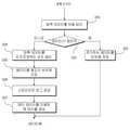
도 3은 본 발명의 실시 예에 따른 플래시 메모리 컨트롤러의 에러 정정 과정을 보인 순서도이고, 도 4는 도 3에 도시된 압축 데이터를 분산 배치하는 과정을 보인 세부적으로 보인 순서도로서, 도 3 및 도 4를 참조하면 호스트로부터 쓰기 명령이 수신되는 경우(과정 310) 생성된 수신된 데이터를 압축하는 과정(320)과 압축된 데이터를 분산 배치하는 과정(330)과, ECC 소스 길이를 적응적으로 가변하는 과정(340)이 도시되어 있다.3 is a flowchart illustrating an error correction process of a flash memory controller according to an exemplary embodiment of the present invention, and FIG. 4 is a detailed flowchart illustrating a process of distributing and arranging compressed data illustrated in FIG. 3. FIGS. 3 and 4. Referring to FIG. 3, when a write command is received from the host (operation 310), the method may include compressing the generated received data (320), distributing and compressing the compressed data (330), and adaptively varying an ECC source length.
즉, 호스트로부터 쓰기 명령이 수신되면(과정 310), RAID 콘트롤러(210)는 수신된 데이터를 압축하여(과정 320) 데이터의 크기 감소된 압축 데이터를 버퍼 메모리 장치의 페이지 버퍼의 어떤 위치에 배치하고 압축으로 인해 미사용된 영역을 1로 기록한다. 여기서, 1은 후단의 낸드 플래시 메모리 장치(20)에 대해 전기적으로 안정된 상태이다.That is, when a write command is received from the host (step 310), the
즉, RAID는 스트라이프에 속하는 블록 그룹 SG(Stripe Group), 스트라이프 내의 칩 번호 CI(Chip Index), 페이지의 크기를 칩 번호로 나눈 값으로 도출된 SB(Scatter Base), 및 SB와 CI의 곱으로 도출된 배치 오프셋 SI(Scatter Index)로 구성된다.That is, RAID is a block group SG (Stripe Group) belonging to a stripe, a chip number CI (Chip Index) in the stripe, a SB (Scatter Base) derived by dividing the page size by a chip number, and a product of SB and CI. It is composed of derived batch offset SI (Scatter Index).
이에 압축된 데이터는 SB와 CI의 곱으로 연산된 배치 오프셋 SI에 배치하는 단계(단계 331), 배치된 데이터가 페이지의 경계를 넘으면(332) 나머지 데이터를 버퍼 메모리 장치의 순환 버퍼에 저장하는 단계(333) 페이지의 0 오프셋부터 배치 단계(단계 334)를 수행한다.The compressed data is placed in a batch offset SI calculated as a product of SB and CI (step 331), and when the arranged data crosses a page boundary (332), storing the remaining data in a circular buffer of the buffer memory device. The placement step (step 334) is performed from the offset 0 of the
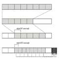
도 5는 도 4에 도시된 분산 배치하는 일련의 과정을 설명하기 위한 예시도로서, 도 5를 참조하면, SG의 블록 수가 4이고 페이지 크기가 8인 경우 데이터 D5는 페이지 오프셋에 배치되고 데이터 D6는 오프셋 2KB에 배치되며, 이러한 압축된 데이터를 순차적으로 분산 배치된다. 즉, 이러한 RAID의 분산 배치에 의해 압축된 데이터의 실제 유효 영역이 줄어들기 때문에 클러스터 그룹 별로 압축 데이터를 복귀할 때 클러스터 그룹 간에 중복되는 페이지 영역만 알면 된다. 이에 따라 클러스터 그룹 내의 흩어져 있는 압축 데이터의 분산 배치로 인해 압축 데이터의 복귀를 위한 클러스터 그룹 내의 실제 연결된 페이지 수가 줄어 들고, 스트라이프 크기는 증가하며, 패리티 오버 헤드는 감소하게 된다. 예를 들어, 압축 데이터 D5를 읽는 동안 오류가 발생되며, 오류를 복구하기 위해 압축 데이터 D6 및 D8 만 필요하고 D7은 필요하지 아니하다.FIG. 5 is an exemplary diagram for describing a series of distributed arrangements illustrated in FIG. 4. Referring to FIG. 5, when the number of blocks of an SG is 4 and the page size is 8, data D5 is disposed at a page offset and data D6. Is arranged at an offset of 2KB, and these compressed data are sequentially distributed. That is, since the effective effective area of the compressed data is reduced by the distributed arrangement of RAID, when recompressing compressed data for each cluster group, only the overlapped page area between cluster groups needs to be known. As a result, the distributed arrangement of the scattered compressed data in the cluster group reduces the number of actually connected pages in the cluster group for the return of the compressed data, increases the stripe size, and reduces the parity overhead. For example, an error occurs while reading compressed data D5, and only compressed data D6 and D8 are needed and D7 is not needed to recover the error.
그리고 부분 스트라이프의 패리티는 전체 스트라이프의 쓰기가 완료될 때까지 버퍼 메모리에 저장된다(단계 335). 이에 수신된 모든 압축 데이터가 새로운 패리티 데이터를 생성하여 낸드 플래시 메모리 장치(20)의 새 위치에 기록된다. 다만, 전체 스트라이프 쓰기가 완료될 때까지 부분 패리티는 버퍼 메모리에 유지되므로 부분 스트라이프 쓰기를 위해 부분 패리티가 생성되므로 실제 부분 패리티 페이지는 없음을 의미한다.The parity of the partial stripe is stored in the buffer memory until writing of the entire stripe is completed (step 335). All the compressed data received therein generates new parity data and is written to a new location of the NAND
다음 RAID 콘트롤러(210)는 런 타임 패리티 오버 헤드를 줄여 전력 손실로 부분적 패리티를 복구하기 위해 스트라이프 로그를 생성한다(단계 336). 이때 스트라이프 로그는 루트 블록, StripeMap 블록, PageMap 블록, StripeMapLog 블록, 및 StripeLogInfo을 포함하며, 전체 스트라이프 정보가 기록된다. 여기서, 스트라이프의 매핑 변경 내용은 StripeLogInfo 구조로 포함하고, 전용 플래스 블록 인 StripeMapLog롤 플래시된다. 또한 전력 손실로 인해 패리티 오류가 발생하고 이에 패리티가 버퍼에 유지되는 경우 호스트 기록 정보를 이용하여 부분 패리티가 복구되므로, 부분 패리티 오버 헤드가 감소된다.The
또한 RAID 콘트롤러(210)는 전술한 스트라이프 로그를 이용하여 생성된 메타 데이터에 대해 맵 테이블을 생성하여 주 메모리 장치(30)에 저장한다(단계 337). 메타 데이터에 유효 데이터 영역의 길이가 맵핑 테이블 메타 데이터가 추가되어 어떤 페이지가 서로 관련되어 복구되는 지가 결정된다. 이때 길이 유효 데이터는 맵핑 테이블 사이즈를 고려하여 한 페이지 내의 유효 영역에 대한 비로 저장된다. 이에 따라 유효 데이터의 길이는 각 엔트리에 대해 1 바이트로 충분하고 이에 따라 레거시 맵핑 관리와 비교하여 볼 때 추가적인 맵핑 테이블 오버 헤드는 작다.In addition, the
도 6은 도 3에 도시된 ECC 소스 길이 적응적으로 가변시키는 일련의 과정을 세부적인 구성을 보인 순서도이고, 도 7은 ECC 소스 길이를 적응적으로 가변시키는 과정을 설명하기 위한 예시도이다. 도 6 및 도 7을 참조하여 과정(320)에 의거 데이터의 압력으로 인해 8개의 서브 페이지는 5개의 서브 페이지로 압축되고 압축된 5개의 서브 페이지의 압축된 ECC의 소스 길이를 고정된 각 페이지의 ECC 수로 나누어 ECC 소스 길이를 설정하고(단계 341), 동일한 수의 ECC 리던던시를 페이지의 추가 영역에 기록하며(단계 342), 및 설정된 ECC 소스 길이로 압축된 ECC에 대해 인코딩을 수행한다(단계 343). 이에 따라 소스 길이가 줄어들고 나머지 부분은 인코딩을 위해 0으로 채워지고 동일한 ECC 리던던시를 갖는 감소된 소스 길이로 인해 더 많은 비트에 대한 정정이 가능하다. 그리고, 데이터의 길이가 디코딩할 수 있는 최대 데이터가 작은 경우 사용하지 아니한 영역의 디코딩을 정지한다. 따라서, ECC 인코딩의 오버 헤드를 감소할 수 있고, 이에 따라 ECC 신뢰도를 증가할 수 있다.FIG. 6 is a flowchart showing a detailed configuration of a series of processes of adaptively varying the ECC source length shown in FIG. 3, and FIG. 7 is an exemplary diagram for describing a process of adaptively varying the ECC source length. Due to the pressure of the data according to the
본 발명의 따르면, 압축 데이터를 페이지의 다른 위치에 배치되고 사용하지 아니한 영역을 패리티 클러스터 내에 분산 배치되므로, 패리티 오버 헤드를 줄일 수 있고, 동일한 RAID 신뢰도 레벨에서 쓰기 증폭 요소를 감소할 수 있으며, 적응적으로 조정된 ECC의 소스 길이로 인해 인코딩되므로 추가 ECC 오버 헤드 없이 ECC에 대한 신뢰도를 향상시킬 수 있게 된다.According to the present invention, since compressed data is disposed at different positions of the page and unused areas are distributed in the parity cluster, parity overhead can be reduced, write amplification factor can be reduced at the same RAID reliability level, and adaptive. As a result, the source length of the adjusted ECC is encoded so that the reliability of the ECC can be improved without additional ECC overhead.
이상과 같이 실시예들이 비록 한정된 실시예와 도면에 의해 설명되었으나, 해당 기술분야에서 통상의 지식을 가진 자라면 상기의 기재로부터 다양한 수정 및 변형이 가능하다. 예를 들어, 설명된 기술들이 설명된 방법과 다른 순서로 수행되거나, 및/또는 설명된 시스템, 구조, 장치, 회로 등의 구성요소들이 설명된 방법과 다른 형태로 결합 또는 조합되거나, 다른 구성요소 또는 균등물에 의하여 대치되거나 치환되더라도 적절한 결과가 달성될 수 있다. 그러므로, 본 발명의 범위는 설명된 실시예에 국한되어 정해져서는 아니 되며, 후술하는 특허청구범위뿐 아니라 이 특허청구범위와 균등한 것들에 의해 정해져야 한다.Although the embodiments have been described by the limited embodiments and the drawings as described above, various modifications and variations are possible to those skilled in the art from the above description. For example, the described techniques may be performed in a different order than the described method, and / or components of the described systems, structures, devices, circuits, etc. may be combined or combined in a different form than the described method, or other components. Or even if replaced or substituted by equivalents, an appropriate result can be achieved. Therefore, the scope of the present invention should not be limited to the described embodiments, but should be determined not only by the claims below but also by the equivalents of the claims.
압축 데이터를 페이지의 다른 위치에 배치되고 사용하지 아니한 영역을 패리티 클러스터 내에 분산 배치되고 적응적으로 조정된 ECC의 소스 길이로 인해 인코딩되므로 되므로, 패리티 오버 헤드를 줄일 수 있고, 동일한 RAID 신뢰도 레벨에서 쓰기 증폭 요소를 감소할 수 있으며, 추가 ECC 오버 헤드 없이 ECC에 대한 신뢰도를 향상시킬 수 있는 플래시 메모리 컨트롤러의 에러 정정 방법에 대한 운용의 정확성 및 신뢰도 측면, 더 나아가 성능 효율 면에 매우 큰 진보를 가져올 수 있으며, 메모리 장치의 시판 또는 영업의 가능성이 충분할 뿐만 아니라 현실적으로 명백하게 실시할 수 있는 정도이므로 산업상 이용가능성이 있는 발명이다.
Since compressed data is placed at different locations on the page and unused areas are distributed within the parity cluster and encoded due to the adaptively adjusted ECC source length, parity overhead can be reduced and writes at the same RAID reliability level. It is possible to reduce the amplification factor and make a major step forward in terms of accuracy and reliability of operation and further performance efficiency for the error correction method of the flash memory controller which can improve the reliability of ECC without additional ECC overhead. In addition, the present invention has industrial applicability because the possibility of marketing or operating a memory device is not only sufficient, but also practically obvious.
Claims (4)
Translated fromKorean쓰기 명령 수신 시 수신된 데이터를 압축하는 과정; 및
압축된 데이터를 RAID 분산 배치하는 과정을 포함하고,
상기 RAID 분산 배치하는 과정은
스트라이프 태에 속하는 블록 그룹 SG(Stripe Group), 스트라이프 그룹 내의 칩 번호 CI(Chip Index), 페이지 사이즈와 CI의 비로부터 도출된 페이지 사이즈 SB(Scatter Base), 및 SB와 CI의 곱으로부터 연산하여 스트라이프 그룹 내의 압축 데이터의 배치 오프셋 값 SI(Scatter Index)을 포함하는 RAID 에 대해,
플래시 컨트롤러에 의해 스트라이프 내에 속하는 블록 그룹 SG(Stripe Group) 내의 부분 스트라이프의 압축 데이터에 대해 SI를 토대로 각 플래시 메모리 칩에 분산 배치하는 단계;
부분 스트라이프의 패리티 데이터를 쓰기가 완료될 때까지 별도의 버퍼 메모리에 저장하는 단계;
모든 스트라이프 로깅을 위해 루트 블록, 스트라이프 맵 블록, 페이지 맵 블록, 및 스트라이프 맵 로그 블록을 포함하는 스트라이프 로그를 생성하고 생성된 스트라이프 로그를 메타 데이터로 기록하는 단계를 포함하는 것을 특징으로 하는 플래시 메모리 컨트롤러의 에러 정정 방법.
In the error correction method of the flash memory controller for controlling the NAND flash memory device,
Compressing the received data upon receiving a write command; And
RAID distribution of the compressed data, and
The process of distributing the RAID distribution
Stripe computed from the block group SG (Stripe Group) belonging to the stripe state, the chip number CI (Chip Index) in the stripe group, the page size SB (Scatter Base) derived from the ratio of page size and CI, and the product of SB and CI For RAID with a batch offset value SI (Scatter Index) of compressed data within a group,
Distributing, by the flash controller, the compressed data of the partial stripes in the block group SG (Stripe Group) belonging to the stripe to each flash memory chip based on the SI;
Storing the parity data of the partial stripe in a separate buffer memory until writing is completed;
Generating a stripe log comprising a root block, a stripe map block, a page map block, and a stripe map log block for all stripe logging and recording the generated stripe log as metadata; Error correction method.
분산 배치된 한 페이지 내의 에러 정정 코드(ECC) 소스 길이를 적응적으로 가변시켜 인코딩하는 과정을 더 포함하는 것을 특징으로 하는 플래시 메모리 컨트롤러의 에러 정정 방법.
The method of claim 1, wherein the error correction method of the flash memory controller is
And adaptively varying and encoding an error correction code (ECC) source length in one distributed page.
압축된 ECC 소스 길이를 고정된 각 페이지의 ECC 수로 나누어 ECC 소스 길이를 설정하는 단계;
동일한 수의 ECC 리던던시를 페이지의 추가 영역에 기록하는 단계; 및
상기 설정된 ECC 소스 길이로 압축된 ECC에 대해 인코딩을 수행하는 단계를 포함하는 것을 특징으로 하는 플래시 메모리 컨트롤러의 에러 정정 방법.
The method of claim 3, wherein the encoding of the adaptive source length comprises:
Setting the ECC source length by dividing the compressed ECC source length by the ECC number of each fixed page;
Recording the same number of ECC redundancy in an additional area of the page; And
And performing encoding on the ECC compressed to the set ECC source length.
Priority Applications (1)
| Application Number | Priority Date | Filing Date | Title |
|---|---|---|---|
| KR1020170178505AKR102032878B1 (en) | 2017-12-22 | 2017-12-22 | Method for correcting error of flash storage controller |
Applications Claiming Priority (1)
| Application Number | Priority Date | Filing Date | Title |
|---|---|---|---|
| KR1020170178505AKR102032878B1 (en) | 2017-12-22 | 2017-12-22 | Method for correcting error of flash storage controller |
Publications (2)
| Publication Number | Publication Date |
|---|---|
| KR20190076589A KR20190076589A (en) | 2019-07-02 |
| KR102032878B1true KR102032878B1 (en) | 2019-10-16 |
Family
ID=67258091
Family Applications (1)
| Application Number | Title | Priority Date | Filing Date |
|---|---|---|---|
| KR1020170178505AExpired - Fee RelatedKR102032878B1 (en) | 2017-12-22 | 2017-12-22 | Method for correcting error of flash storage controller |
Country Status (1)
| Country | Link |
|---|---|
| KR (1) | KR102032878B1 (en) |
Cited By (2)
| Publication number | Priority date | Publication date | Assignee | Title |
|---|---|---|---|---|
| US11194661B1 (en) | 2020-06-09 | 2021-12-07 | SK Hynix Inc. | Memory system for accessing data in stripe form and operating method thereof |
| KR102870388B1 (en) | 2021-09-08 | 2025-10-14 | 양쯔 메모리 테크놀로지스 씨오., 엘티디. | Data protection method for memory and memory device thereof |
Families Citing this family (1)
| Publication number | Priority date | Publication date | Assignee | Title |
|---|---|---|---|---|
| KR20240048955A (en) | 2022-10-07 | 2024-04-16 | 삼성전자주식회사 | A storage device operated by zone and data processing system including the same |
Citations (1)
| Publication number | Priority date | Publication date | Assignee | Title |
|---|---|---|---|---|
| KR101274950B1 (en) | 2006-05-12 | 2013-06-17 | 애플 인크. | Memory device with adaptive capacity |
Family Cites Families (4)
| Publication number | Priority date | Publication date | Assignee | Title |
|---|---|---|---|---|
| JPH08123627A (en)* | 1994-10-20 | 1996-05-17 | Fuji Xerox Co Ltd | Disk array device |
| US8019938B2 (en)* | 2006-12-06 | 2011-09-13 | Fusion-I0, Inc. | Apparatus, system, and method for solid-state storage as cache for high-capacity, non-volatile storage |
| US10432353B2 (en)* | 2014-12-04 | 2019-10-01 | Samsung Display Co., Ltd. | Memory-efficient methods of transporting error correction codes in a symbol encoded transmission stream |
| KR101889864B1 (en)* | 2016-06-13 | 2018-08-21 | 주식회사 래코랩 | Nand flash memory controller using compression rate and nand flash memory storing method using the same |
- 2017
- 2017-12-22KRKR1020170178505Apatent/KR102032878B1/ennot_activeExpired - Fee Related
Patent Citations (1)
| Publication number | Priority date | Publication date | Assignee | Title |
|---|---|---|---|---|
| KR101274950B1 (en) | 2006-05-12 | 2013-06-17 | 애플 인크. | Memory device with adaptive capacity |
Cited By (2)
| Publication number | Priority date | Publication date | Assignee | Title |
|---|---|---|---|---|
| US11194661B1 (en) | 2020-06-09 | 2021-12-07 | SK Hynix Inc. | Memory system for accessing data in stripe form and operating method thereof |
| KR102870388B1 (en) | 2021-09-08 | 2025-10-14 | 양쯔 메모리 테크놀로지스 씨오., 엘티디. | Data protection method for memory and memory device thereof |
Also Published As
| Publication number | Publication date |
|---|---|
| KR20190076589A (en) | 2019-07-02 |
Similar Documents
| Publication | Publication Date | Title |
|---|---|---|
| US10592173B2 (en) | Increasing storage efficiency of a data protection technique | |
| JP6855102B2 (en) | Recovery from multi-page failure in non-volatile memory systems | |
| US9946642B2 (en) | Distributed multimode storage management | |
| US10884914B2 (en) | Regrouping data during relocation to facilitate write amplification reduction | |
| JP6606039B2 (en) | Memory system and control method | |
| US8910017B2 (en) | Flash memory with random partition | |
| TWI702495B (en) | Apparatus, method, and multimode storage device for performing selective underlying exposure mapping on user data | |
| TWI716416B (en) | Storage system, method and system for managing storage media, method of operating storage system, and non-transitory computer-readable medium | |
| CN107787489B (en) | File storage system including a hierarchy | |
| US8578127B2 (en) | Apparatus, system, and method for allocating storage | |
| US8904261B2 (en) | Data management in solid state storage devices | |
| US8959280B2 (en) | Super-endurance solid-state drive with endurance translation layer (ETL) and diversion of temp files for reduced flash wear | |
| US9552290B2 (en) | Partial R-block recycling | |
| US20160217040A1 (en) | Raid parity stripe reconstruction | |
| US11340986B1 (en) | Host-assisted storage device error correction | |
| TW201729102A (en) | Storage device and method | |
| KR20120071058A (en) | Data storage device and operating method thereof | |
| US10996886B2 (en) | Method and system for facilitating atomicity and latency assurance on variable sized I/O | |
| KR20180051703A (en) | Storage device storing data in raid manner | |
| US11487609B2 (en) | Separating parity data from host data in a memory sub-system | |
| JP6342013B2 (en) | Method, system and computer program for operating a data storage system including a non-volatile memory array | |
| KR20220103378A (en) | Apparatus and method for handling data stored in a memory system | |
| KR102032878B1 (en) | Method for correcting error of flash storage controller | |
| US11934264B2 (en) | ECC parity biasing for Key-Value data storage devices | |
| US12032843B2 (en) | Apparatus and method for increasing operation efficiency in data processing system |
Legal Events
| Date | Code | Title | Description |
|---|---|---|---|
| A201 | Request for examination | ||
| PA0109 | Patent application | St.27 status event code:A-0-1-A10-A12-nap-PA0109 | |
| PA0201 | Request for examination | St.27 status event code:A-1-2-D10-D11-exm-PA0201 | |
| P11-X000 | Amendment of application requested | St.27 status event code:A-2-2-P10-P11-nap-X000 | |
| P13-X000 | Application amended | St.27 status event code:A-2-2-P10-P13-nap-X000 | |
| D13-X000 | Search requested | St.27 status event code:A-1-2-D10-D13-srh-X000 | |
| D14-X000 | Search report completed | St.27 status event code:A-1-2-D10-D14-srh-X000 | |
| PG1501 | Laying open of application | St.27 status event code:A-1-1-Q10-Q12-nap-PG1501 | |
| E902 | Notification of reason for refusal | ||
| PE0902 | Notice of grounds for rejection | St.27 status event code:A-1-2-D10-D21-exm-PE0902 | |
| E13-X000 | Pre-grant limitation requested | St.27 status event code:A-2-3-E10-E13-lim-X000 | |
| P11-X000 | Amendment of application requested | St.27 status event code:A-2-2-P10-P11-nap-X000 | |
| P13-X000 | Application amended | St.27 status event code:A-2-2-P10-P13-nap-X000 | |
| E701 | Decision to grant or registration of patent right | ||
| PE0701 | Decision of registration | St.27 status event code:A-1-2-D10-D22-exm-PE0701 | |
| GRNT | Written decision to grant | ||
| PR0701 | Registration of establishment | St.27 status event code:A-2-4-F10-F11-exm-PR0701 | |
| PR1002 | Payment of registration fee | St.27 status event code:A-2-2-U10-U11-oth-PR1002 Fee payment year number:1 | |
| PG1601 | Publication of registration | St.27 status event code:A-4-4-Q10-Q13-nap-PG1601 | |
| PR1001 | Payment of annual fee | St.27 status event code:A-4-4-U10-U11-oth-PR1001 Fee payment year number:4 | |
| PR1001 | Payment of annual fee | St.27 status event code:A-4-4-U10-U11-oth-PR1001 Fee payment year number:5 | |
| PC1903 | Unpaid annual fee | St.27 status event code:A-4-4-U10-U13-oth-PC1903 Not in force date:20241011 Payment event data comment text:Termination Category : DEFAULT_OF_REGISTRATION_FEE | |
| PC1903 | Unpaid annual fee | St.27 status event code:N-4-6-H10-H13-oth-PC1903 Ip right cessation event data comment text:Termination Category : DEFAULT_OF_REGISTRATION_FEE Not in force date:20241011 |