KR102031821B1 - Slotted array antenna - Google Patents
Slotted array antennaDownload PDFInfo
- Publication number
- KR102031821B1 KR102031821B1KR1020170048712AKR20170048712AKR102031821B1KR 102031821 B1KR102031821 B1KR 102031821B1KR 1020170048712 AKR1020170048712 AKR 1020170048712AKR 20170048712 AKR20170048712 AKR 20170048712AKR 102031821 B1KR102031821 B1KR 102031821B1
- Authority
- KR
- South Korea
- Prior art keywords
- receiving plate
- waveguide
- array antenna
- slot array
- broadcast signal
- Prior art date
- Legal status (The legal status is an assumption and is not a legal conclusion. Google has not performed a legal analysis and makes no representation as to the accuracy of the status listed.)
- Expired - Fee Related
Links
Images


Classifications
- H—ELECTRICITY
- H01—ELECTRIC ELEMENTS
- H01Q—ANTENNAS, i.e. RADIO AERIALS
- H01Q13/00—Waveguide horns or mouths; Slot antennas; Leaky-waveguide antennas; Equivalent structures causing radiation along the transmission path of a guided wave
- H01Q13/10—Resonant slot antennas
- H—ELECTRICITY
- H01—ELECTRIC ELEMENTS
- H01P—WAVEGUIDES; RESONATORS, LINES, OR OTHER DEVICES OF THE WAVEGUIDE TYPE
- H01P3/00—Waveguides; Transmission lines of the waveguide type
- H01P3/02—Waveguides; Transmission lines of the waveguide type with two longitudinal conductors
- H01P3/023—Fin lines; Slot lines
- H—ELECTRICITY
- H01—ELECTRIC ELEMENTS
- H01Q—ANTENNAS, i.e. RADIO AERIALS
- H01Q1/00—Details of, or arrangements associated with, antennas
- H01Q1/27—Adaptation for use in or on movable bodies
- H01Q1/32—Adaptation for use in or on road or rail vehicles
Landscapes
- Waveguide Aerials (AREA)
- Variable-Direction Aerials And Aerial Arrays (AREA)
Abstract
Translated fromKoreanDescription
Translated fromKorean본 발명은 특히 차량에 설치되어 방송위성에서 송신하는 방송신호를 수신하되, 안테나 시스템 전체의 설치높이와 설치면적을 감소시킬 수 있는 슬롯 어레이 안테나에 관한 것이다.The present invention relates to a slot array antenna, which is installed in a vehicle and receives a broadcast signal transmitted from a broadcast satellite, but can reduce the installation height and installation area of the entire antenna system.
차량용 위성방송신호 수신 안테나는, 높이 제한이 있는 노상을 주행하는 차량의 정상부 등에 설치되는 것이어서 안테나 시스템 전체의 설치높이를 감소시키는 것이 중요한 기술과제의 하나이며, 한정된 면적의 차량 정상부에 설치되는 것이어서 안테나 시스템 전체의 설치면적을 감소시키는 것도 중요한 기술과제의 하나이다.Since the satellite broadcasting signal receiving antenna for a vehicle is installed at the top of a vehicle traveling on a road with limited height, it is one of the important technical tasks to reduce the installation height of the entire antenna system, and the antenna is installed at the top of a limited area vehicle. Reducing the footprint of the system as a whole is another important challenge.
차량용 위성방송신호 수신 안테나는 수신 안테나가 차량의 이동에 따라 차량과의 상대적인 위치가 시시각각 변하는 방송위성을 상시 포착하도록, 그 방위각과 앙각을 제어하는 추적기구가 필요하게 된다. 이 추적기구는 안테나 시스템 전체의 제조비용을 상당부분 차지할 뿐만 아니라 안테나 시스템 전체의 설치높이나 설치면적도 증대시키는 문제가 있기 때문에, 이것을 간략화하는 것이 중요한 기술 과제의 하나이다. 방위각의 변화는 차량의 이동에 수반해 360°에 걸쳐서 발생하므로, 방위각 방향의 추적을 기계적인 회전 기구로 실현할 필요가 있다. 이것과는 대조적으로 앙각의 변화는 위도나 도로의 경사에 따라 발생하는 것이기 때문에 그 변화 범위는 비교적 한정되어 있다. 이 때문에 앙각 방향의 기계적 추적을 하지 않는 무추적 방식을 이용하면, 안테나 시스템 전체의 경제화를 도모할 수 있다.The vehicle satellite broadcasting signal receiving antenna requires a tracking mechanism for controlling the azimuth and elevation angles so that the reception antenna always captures a broadcasting satellite whose position relative to the vehicle changes with time as the vehicle moves. This tracking mechanism not only accounts for a large part of the manufacturing cost of the entire antenna system, but also increases the installation height and installation area of the entire antenna system. Therefore, it is one of the important technical problems. Since a change in azimuth occurs over 360 ° with movement of the vehicle, it is necessary to realize tracking in the azimuth direction with a mechanical rotating mechanism. In contrast, since the change in elevation is caused by latitude or inclination of the road, the change range is relatively limited. For this reason, the use of an inverted method that does not perform mechanical tracking in the elevation direction can improve the overall antenna system.
종래 국내에 보급된 차량용 수신 안테나는 방송위성과의 앙각 매칭을 위하여 안테나를 지면에서 45°정도 기울여 설치함으로써 안테나 시스템 전체의 설치높이가 15cm 이상으로 높다는 문제점과, 회전반경이 커 안테나 시스템 전체의 설치면적도 크다는 문제점이 있었다. 이 같은 문제점은 버스나 트럭이 아닌 개인용 차량에 차량용 위성방송신호 수신 안테나가 보급되는데 제약이 되었다.Conventionally, the receiving antenna for a vehicle, which has been widely distributed in Korea, has a problem that the installation height of the entire antenna system is higher than 15 cm by installing the antenna at an angle of 45 ° from the ground to match the elevation angle with the broadcasting satellite, and the installation area of the entire antenna system is large due to the large rotation radius. There was a big problem. This problem has been limited in the spread of satellite broadcasting signal receiving antennas for vehicles in personal vehicles other than buses and trucks.
본 발명은 상기한 문제점을 해결하기 위하여 도출된 것으로서, 안테나 시스템 전체의 설치높이와 설치면적을 감소시킬 수 있는 차량용 위성방송신호 수신 슬롯 어레이 안테나를 구현하는데 목적이 있다.The present invention has been made to solve the above problems, and an object of the present invention is to implement a satellite broadcasting signal receiving slot array antenna for a vehicle, which can reduce the installation height and the installation area of the entire antenna system.
상기와 같은 목적을 달성하기 위하여, 본 발명에 따른 슬롯 어레이 안테나는, X자 형상으로 천공된 복수개의 슬롯이 세로열을 다수개 만들고, 어느 하나의 세로열은 이와 인접하는 세로열과 평행하게 배치되어 있는 수신판; 상기 수신판과 결합되는 받침판; 상기 수신판과 상기 받침판이 결합되어 형성되며, 서로 평행하게 배열된 복수의 제1도파관; 상기 제1도파관의 일단과 연통되며, 상기 제1도파관의 길이방향과 수직방향으로 형성되는 제2도파관; 및 상기 제2도파관 중심부의 합성구조물;을 포함하되, 상기 슬롯 어레이 안테나의 앙각포인트는 상기 제1도파관의 좌우폭에 따라 결정되는 것을 특징으로 한다.In order to achieve the above object, in the slot array antenna according to the present invention, a plurality of slots perforated in the X-shape make a plurality of vertical columns, any one of the vertical columns are arranged in parallel with the adjacent vertical columns Receiving plate; Support plate coupled to the receiving plate; A plurality of first waveguides formed by coupling the receiving plate and the receiving plate and arranged in parallel to each other; A second waveguide communicating with one end of the first waveguide and formed in a direction perpendicular to a length direction of the first waveguide; And a composite structure at the center of the second waveguide, wherein the elevation angle of the slot array antenna is determined according to the left and right widths of the first waveguide.
여기서, 상기 수신판이 지면과 -5° 이상 +5° 이하의 소정의 각을 이루고 설치된 경우, 상기 제1도파관의 좌우폭이 형성되는 수치범위 중 최소값은 13.4mm 이상이고 최대값은 15.8mm 이하가 되는 것을 특징으로 한다.Here, when the receiving plate is installed at a predetermined angle of -5 ° or more and + 5 ° or less with the ground, the minimum value of the numerical range in which the left and right widths of the first waveguide are formed is 13.4 mm or more and the maximum value is 15.8 mm or less. It is characterized by.
또한, 상기 수신판이 지면과 수평하게 설치된 경우, 상기 제1도파관의 좌우폭은 14.0~15.0mm인 것을 특징으로 한다.In addition, when the receiving plate is installed horizontally with the ground, the left and right width of the first waveguide is characterized in that 14.0 ~ 15.0mm.
또한, 상기 수신판과 받침판에는 상기 수신판과 받침판 각각의 중심부를 관통하는 홀이 형성되어 있는 것을 특징으로 한다.In addition, the receiving plate and the support plate is characterized in that a hole penetrating through the center of each of the receiving plate and the support plate is formed.
또한, 상기 수신판의 중심부에 배치된 세로열의 슬롯 개수보다 상기 수신판의 말단부에 배치된 세로열의 슬롯 개수가 적으며, 그에 대응되도록 상기 수신판 중심부의 세로방향의 길이보다 상기 수신판 말단부의 세로방향의 길이가 짧은 것을 특징으로 한다.In addition, the number of slots in the vertical column disposed at the distal end of the receiving plate is smaller than the number of slots in the vertical column disposed in the center of the receiving plate, and the corresponding length of the receiving plate end portion is greater than the length of the vertical direction of the receiving plate center so as to correspond thereto. It is characterized by the short length of the direction.
본 발명에 의하면, 안테나 시스템 전체의 설치높이와 설치면적을 감소시킬 수 있는 차량용 위성방송신호 수신 안테나를 구현할 수 있는 이점이 있다. 따라서, 버스나 트럭이 아닌 개인용 차량에도 차량용 위성방송신호 수신 안테나가 보급되는데 큰 기여가 될 수 있다.According to the present invention, there is an advantage that can implement a satellite broadcasting signal receiving antenna for a vehicle that can reduce the installation height and the installation area of the entire antenna system. Therefore, it may be a great contribution to the spread of satellite broadcasting signal receiving antennas for vehicles in personal vehicles other than buses and trucks.
도 1은 종래의 슬롯 어레이 안테나의 개략도이다.
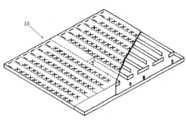
도 2는 본 발명에 따른 슬롯 어레이 안테나(1)의 사시도이다.
도 3은 상부에서 본 슬롯 어레이 안테나(1)의 분해 사시도이다.
도 4는 하부에서 본 슬롯 어레이 안테나(1)의 분해 사시도이다.
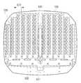
도 5는 수신판(100)의 후면도이다.
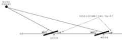
도 6은 한국의 지역적범위 설정에 대한 개념도이다.
도 7은 수신판(100)을 지면에서 +5° 기울여 설치한 경우의 개념도이다.
도 8은 수신판(100)을 지면에서 -5° 기울여 설치한 경우의 개념도이다.
도 9는 앙각포인팅오차에 대한 방송신호손실값 및 방송신호손실률을 나타낸 표이다.
도 10은 슬롯 어레이 안테나(1)의 제1도파관의 좌우폭(121)에 대응하는 슬롯 어레이 안테나(1)의 앙각포인트를 나타낸 표이다.
도 11은 빔포밍 전후의 메인로브 및 사이드로브 세기를 비교한 그래프이다.1 is a schematic diagram of a conventional slot array antenna.
2 is a perspective view of a
3 is an exploded perspective view of the
4 is an exploded perspective view of the
5 is a rear view of the receiving
6 is a conceptual diagram for setting a regional range in Korea.
FIG. 7 is a conceptual diagram when the receiving
8 is a conceptual diagram when the
9 is a table illustrating a broadcast signal loss value and a broadcast signal loss rate for an elevation pointing error.
FIG. 10 is a table illustrating elevation angles of the
11 is a graph comparing main lobe and side lobe strengths before and after beamforming.
이하 도면을 참조하여 본 발명에 관하여 살펴보기로 하며, 본 발명을 설명함에 있어서 관련된 공지기술 또는 구성에 대한 구체적인 설명이 본 발명의 요지를 불필요하게 흐릴 수 있다고 판단되는 경우에는 그 상세한 설명은 생략할 것이다.Hereinafter, the present invention will be described with reference to the accompanying drawings. In describing the present invention, when it is determined that the detailed description of the related well-known technology or configuration may unnecessarily obscure the gist of the present invention, the detailed description thereof will be omitted. will be.
도 1은 종래의 슬롯 어레이 안테나(10)의 도면이다.1 is a diagram of a conventional
도 2는 본 발명에 따른 슬롯 어레이 안테나(1)의 사시도이며, 도 3 및 도 4는 슬롯 어레이 안테나(1)를 각각 상부와 하부에서 본 분해 사시도이다.2 is a perspective view of a
본 발명에 따른 슬롯 어레이 안테나(1)는 수신판(100)과 받침판(200)으로 구성되며, 수신판(100)의 하면과 받침판(200)의 상면이 결합되는 구조이다.
받침판(200)은 수신판(100)과 결합하여 그 사이에 제1도파관 및 제2도파관이 형성되도록 한다.The supporting
수신판(100)은 방송신호(예를 들어, 위성방송신호)를 수신하는 기능을 수행하며, 수신판(100)에는 X자 형상으로 천공된 복수개의 슬롯(110)이 세로열(111)을 다수개 만들고, 어느 하나의 세로열(111)은 이와 인접하는 세로열(111)과 평행하게 배치된다.The
수신판(100)의 하면에는 세로열(111)을 따라 제1오목부(120)가 형성되어 있고, 수신판(100)과 받침판(200)이 결합되면 상기 제1오목부(120)이었던 공간이 방송신호가 전송되는 통로로 되어 제1도파관이 형성된다.The lower surface of the
수신판(100)의 하면에는 제1오목부(120)의 일단과 연통되는 제2오목부(130)가 형성되어 있고, 수신판(100)과 받침판(200)이 결합되면 상기 제2오목부(130)이었던 공간이 방송신호가 전송되는 통로로 되어 제2도파관이 형성된다.A
상기 제1도파관은 수신판(100)이 수신한 방송신호를 상기 제2도파관으로 전송하는 기능을 수행하며, 제1도파관은 세로열(111)의 길이방향과 마찬가지로 세로방향으로 형성된다. 또한 제1도파관의 개수는 세로열(111)의 개수와 동일하다.The first waveguide transmits a broadcast signal received by the
상기 제2도파관은 상기 제1도파관에서 전송된 방송신호를 컨버터로 전송하는 기능을 수행하며, 제2도파관은 세로열(100)의 길이방향과 수직하게 가로방향으로 형성된다.The second waveguide performs a function of transmitting a broadcast signal transmitted from the first waveguide to the converter, and the second waveguide is formed in a horizontal direction perpendicular to the longitudinal direction of the
수신판(100) 및 제2도파관은 수신판(100)의 세로중심축을 기준으로 좌우대칭을 이루고, 제1도파관은 상기 세로중심축을 기준으로 좌우대칭으로 배치된다.The
제2오목부(130)의 중심부에는 합성구조물(131)이 형성되어 있으며, 합성구조물(131)은 상기 좌우대칭으로 배열된 제1도파관에서 전송된 방송신호를 합성하는 기능을 수행한다. 단, 상기 합성구조물(131)의 모양 또는 구조는 도 5에 도시된 바와 같이 반드시 삼각형일 필요는 없으며 원형, 타원형, 다변형 등 다양한 구조를 가질 수 있다.A
본 발명의 슬롯 어레이 안테나(1)는 다음과 같은 원리로 작동된다.The
①수신판(100)으로 방송신호가 수신된다. ②상기 수신된 방송신호는 슬롯(110)을 통해 제1도파관으로 유입된다. ③상기 제1도파관으로 유입된 방송신호는 제2도파관으로 전송된다. ④상기 제2도파관으로 전송된 방송신호는 합성구조물(131)에 의해 합성되며, 합성된 방송신호는 컨버터로 전송된다. ⑤이후 상기 합성되어 컨버터로 전송된 방송신호는 전기적신호로 변환되어 디스플레이(예를들어, TV등)를 통해 출력된다.① The broadcast signal is received by the
본 발명의 슬롯 어레이 안테나(1)는 다음과 같은 원리로 설계된다.The
현재 국내에는 위성방송 SkyLife가 서비스되고 있으며, 이는 방송위성 무궁화 6호(동경 116도)에서 방송신호를 송신함으로써 이루어진다. 본 발명인 슬롯 어레이 안테나(1)는 방송위성 무궁화 6호에서 송신하는 방송신호를 수신할 수 있다.At present, satellite broadcasting SkyLife is being serviced in Korea, and this is done by transmitting a broadcast signal from broadcasting satellite Mugunghwa 6 (116 degrees long). The
앙각이란 수신판(100)에 들어오는 방송신호의 입사방향과 수신판(100)이 이루는 각도(즉, 수신판(100)과 방송위성 무궁화 6호가 이루는 각)를 이르는데, 상기 앙각은 수신판(100)이 지면과 이루는 각도뿐만 아니라 차량의 위도(즉, 슬롯 어레이 안테나(1)가 위치한 지역의 위도) 또한 변수로 작용한다. 수신판(100)이 지면과 이루는 각도란, 수신판(100) 자체를 지면에서 일정 각도 기울여 설치한 경우를 의미한다. 지면은 굴곡이 없는 평면이라고 가정하고, 수신판(100)이 지면과 평행하게 설치되는 경우를 우선 살펴본다.The elevation angle refers to the angle between the incident direction of the broadcast signal entering the
상기한 바와 같이 차량의 위도가 앙각의 변수로 작용하므로 우선 한국의 지역적 범위를 설정해야 하는 바, 한국의 지역적 범위의 북단과 남단을 북단지역과 남단지역이라 한다. 슬롯 어레이 안테나(1)가 속초에 있을 때 수신판(100)과 방송위성 무궁화 6호와의 앙각은 43.8˚이고, 슬롯 어레이 안테나(1)가 목포에 있을 때 수신판(100)과 방송위성 무궁화 6호와의 앙각은 48.1˚이다. 도 6을 참조하면, 이를 기준으로, 슬롯 어레이 안테나(1)가 북단지역에 있을 때의 앙각을 43.0˚, 남단지역에 있을 때의 앙각을 49.0˚인 것으로 설정한다.As described above, since the latitude of the vehicle acts as a variable of the elevation angle, it is necessary to first set the regional range of Korea. The northern and southern ends of the regional range of Korea are referred to as the northern and southern ends. When the
한편, 슬롯 어레이 안테나(1)는 수신판(100)으로 방송신호가 특정한 방향으로 입사될 때 가장 우수한 방송신호수신율을 보이는 특성을 갖는다. 상기 가장 우수한 방송신호수신율을 보이는 특정한 방향으로 방송신호가 입사될 때의 수신판(100)과 방송신호가 이루는 각을 이하 앙각포인트(즉, 슬롯 어레이 안테나(1)의 앙각포인트)라 한다.On the other hand, the
따라서 앙각과 앙각포인트의 차이가 작을수록 방송신호손실률이 작아지며, 앙각과 앙각포인트의 차이가 커질수록 방송신호손실률이 커진다. 앙각과 앙각포인트의 차이를 이하 앙각포인팅오차라 한다.Therefore, the smaller the difference between the elevation angle and the elevation angle, the smaller the broadcast signal loss rate, and the larger the difference between the elevation angle and the elevation angle point, the greater the broadcast signal loss rate. The difference between the elevation angle and the elevation angle is hereinafter referred to as an elevation pointing error.
여기서, 앙각포인트는 슬롯 어레이 안테나(1)의 제1도파관의 좌우폭(121)에 따라 결정된다. 도 5를 참조하면, 제1도파관의 좌우폭(121)이란, 세로열(111)을 따라 형성된 제1오목부(120)의 너비를 의미한다. 상세하게 제1오목부(120)의 너비란, 세로방향으로 기다란 직사각형 형상인 제1오목부(120)에서 가로방향의 길이이다.Here, the elevation angle is determined according to the left and
제1도파관의 좌우폭(121)이 동일한 슬롯 어레이 안테나(1)라 하여도 방송위성 무궁화 6호에 탑재된 각 중계기에 대응되는 슬롯 어레이 안테나(1)의 앙각포인트는 조금씩 다르다. 이는 각 중계기마다 송신하는 방송신호의 주파수가 달라, 각 주파수마다 슬롯 어레이 안테나(1)가 발현하는 특성이 다르기 때문이다.Even if the
한편, 차량용 위성방송신호 수신 안테나는 방송신호를 수신하여 디스플레이를 통해 출력하는데 필요한 방송신호세기(즉, 방송끊김현상이 없는 방송신호세기)에 일정량의 마진(margin)을 두고 설계한다. 본 발명인 슬롯 어레이 안테나(1)는 방송신호를 수신하여 디스플레이를 통해 출력하는데 필요한 방송신호세기에 추가로 3dB의 마진을 두고 설계한다. 국내 위성방송 Skylife가 송신하는 주파수는 20GHz 미만의 Ku-Band 대역이며, 해당 대역의 특성상 방송신호세기에 3dB의 마진을 두면 외부영향(예를 들어, 위도의 변화)에 대한 보상이 가능하기 때문이다. 도 9를 참조하면, 2.99dB(약 3dB)에 해당하는 방송신호손실률은 49.77%(약 50%)이므로, 방송신호손실률이 49.77%가 될 때까지는 위성방송을 디스플레이를 통해 시청하는데 지장이 없다. 방송신호손실률이 49.77% 이상이 되면 위성방송을 디스플레이를 통해 시청하는 과정에서 방송끊김현상이 발생하게 된다. 따라서 방송신호손실률 49.77%를 임계점으로 하여 수치범위를 산출하면 제1도파관의 좌우폭(121)이 14.0~15.0mm가 된다.On the other hand, the vehicle satellite broadcast signal receiving antenna is designed with a certain amount of margin on the broadcast signal strength (that is, broadcast signal strength without broadcast interruption) required to receive and output the broadcast signal through the display. The
도 6, 도 9 및 도 10을 참조하여 상기 수치범위 산출방법에 대해 기술하면, 북단지역의 경우, 수신판(100)과 방송위성 무궁화 6호와의 앙각은 43.0˚가 되고, 방송신호손실률 49.77%에 해당하는 앙각포인팅오차는 ±8˚이다. 따라서 앙각포인팅오차가 +8°일 때 슬롯 어레이 안테나(1)의 앙각포인트는 51.0°, 앙각포인팅오차가 -8°일 때 슬롯 어레이 안테나(1)의 앙각포인트는 35.0°가 되어야 한다. 51.0°의 앙각포인트를 갖는 제1도파관의 좌우폭(121)은 14.0mm가 되고, 35.0°의 앙각포인트를 갖는 제1도파관의 좌우폭(121)은 16.0mm가 된다. 정리하면, 북단지역에서 슬롯 어레이 안테나(1)의 방송신호손실률이 49.77%를 넘기지 않기 위해서는 제1도파관의 좌우폭(121)이 14.0~16.0mm가 되도록 설계되어야 한다. 이는 BS1번 중계기가 송신하는 방송신호까지도 수신할 수 있는 수치범위이다.Referring to FIGS. 6, 9, and 10, the numerical range calculation method is described. For the northern end region, the elevation angle between the
남단지역의 경우, 수신판(100)과 방송위성 무궁화 6호와의 앙각은 49.0˚가 되고, 방송신호손실률 49.77%에 해당하는 앙각포인팅오차는 ±8˚이다. 따라서 앙각포인팅오차가 +8°일 때 슬롯 어레이 안테나(1)의 앙각포인트는 57.0°, 앙각포인팅오차가 -8°일 때 슬롯 어레이 안테나(1)의 앙각포인트는 41.0°가 되어야 한다. 57.0°의 앙각포인트를 갖는 제1도파관의 좌우폭(121)은 13.3mm가 되고, 41.0°의 앙각포인트를 갖는 제1도파관의 좌우폭(121)은 15.0mm가 된다. 정리하면, 남단지역에서 슬롯 어레이 안테나(1)의 방송신호손실률이 49.77%를 넘기지 않기 위해서는 제1도파관의 좌우폭(121)이 13.3~15.0mm가 되도록 설계되어야 한다. 이는 BS6번 중계기가 송신하는 방송신호까지도 수신할 수 있는 수치범위이다.In the southern end region, the elevation angle between the
상기 산출한 범위를 종합하면, 제1도파관의 좌우폭(121)의 범위는 14.0~15.0mm가 된다. 그러므로 슬롯 어레이 안테나(1)의 제1도파관의 좌우폭(121)이 14.0~15.0mm로 설계되면 한국의 전 지역에서 방송신호를 방송끊김현상 없이 수신할 수 있으며, 이는 BS1번 중계기 부터 BS6번 중계기가 송신하는 방송신호까지 모두 포함하여 수신할 수 있는 수치범위이다.In summary, the range of left and
상기 설정한 북단지역과 남단지역에서 방송신호손실률이 49.77%이므로, 그 사이에 위치한 지역에서는 슬롯 어레이 안테나(1)의 방송신호손실률이 49.77% 미만이 되는 것은 자명하다.Since the broadcast signal loss rate is 49.77% in the north end region and the south end region, the broadcast signal loss rate of the
종래 차량용 위성방송신호 수신 안테나를 지면에서 45°정도 기울여 설치하는 방식에서, 안테나를 지면과 평행하게 설치함에도 방송신호수신이 가능해짐에 따라 차량용 수신 안테나의 설치높이를 15cm 이상에서 5cm 이하로 낮출 수 있다.In the conventional method of installing the satellite broadcasting signal receiving antenna for a vehicle by tilting the angle of about 45 ° from the ground, the installation height of the vehicle receiving antenna can be lowered from 15 cm or more to 5 cm or less as the broadcasting signal can be received even when the antenna is installed in parallel with the ground. have.
한편, 슬롯 어레이 안테나(1)를 지면과 수평하게 설치하는 경우 외에도, 수신판(100) 자체를 지면에서 소정의 각을 기울여 설치함으로써 제1도파관의 좌우폭(121)을 달리하는 방법이 고려될 수 있다. 수신판(100)을 지면에서 5˚ 기울이게 되면 안테나 시스템 전체의 설치높이가 약 8.7% 정도 증대되는데, 상기 소정의 각을 5˚로 설정하여 수신판(100)을 지면에서 5˚ 이하로 기울여 설치하는 실시예에 대해 기술한다.Meanwhile, in addition to installing the
수신판(100)을 지면에서 ±5˚ 기울여 설치하면(도 7은 수신판(100)을 지면에서 +5˚ 기울여 설치한 경우이고, 도 8은 수신판(100)을 지면에서 -5˚ 기울여 설치한 경우임) 수신판(100)과 방송위성 무궁화 6호와의 앙각이 ±5˚ 만큼 변화되고, 따라서 북단지역과 남단지역에서 방송신호손실률 49.77%를 기준으로 하여 수신판(100)이 지면과 평행하게 설치되는 경우 수치범위를 산출한 방법과 동일한 방식을 적용하여, 그에 대응되는 제1도파관의 좌우폭(121)의 수치범위를 산출하면 지면과 수신판(100)의 각이 +5˚인 경우 13.4~14.3mm, 지면과 수신판(100)의 각이 -5˚인 경우 14.6~15.8mm의 값을 갖게 된다.When the
도 7을 참조하면, 수신판(100)을 지면에서 +5˚ 기울이게 되면 북단지역의 경우, 수신판(100)과 방송위성 무궁화 6호와의 앙각은 48.0˚가 되고, 방송신호손실률 49.77%에 해당하는 앙각포인팅오차는 ±8˚이다. 따라서 앙각포인팅오차가 +8°일 때 슬롯 어레이 안테나(1)의 앙각포인트는 56.0°, 앙각포인팅오차가 -8°일 때 슬롯 어레이 안테나(1)의 앙각포인트는 40.0°가 되어야 한다. 56.0°의 앙각포인트를 갖는 제1도파관의 좌우폭(121)은 13.4mm가 되고, 40.0°의 앙각포인트를 갖는 제1도파관의 좌우폭(121)은 15.1mm가 된다. 정리하면, 수신판(100)을 지면에서 +5° 기울이게 되면, 북단지역에서 슬롯 어레이 안테나(1)의 방송신호손실률이 49.77%를 넘기지 않기 위해서는 제1도파관의 좌우폭(121)이 13.4~15.1mm가 되도록 설계되어야 한다. 이는 BS1번 중계기가 송신하는 방송신호까지도 수신할 수 있는 수치범위이다.Referring to FIG. 7, when the
수신판(100)을 지면에서 +5˚ 기울이게 되면 남단지역의 경우, 수신판(100)과 방송위성 무궁화 6호와의 앙각은 54.0˚가 되고, 방송신호손실률 49.77%에 해당하는 앙각포인팅오차는 ±8˚이다. 따라서 앙각포인팅오차가 +8°일 때 슬롯 어레이 안테나(1)의 앙각포인트는 62.0°, 앙각포인팅오차가 -8°일 때 슬롯 어레이 안테나(1)의 앙각포인트는 46.0°가 되어야 한다. 62.0°의 앙각포인트를 갖는 제1도파관의 좌우폭(121)은 13.2mm이하의 특정 값이 되고, 46.0°의 앙각포인트를 갖는 제1도파관의 좌우폭(121)은 14.3mm가 된다. 정리하면, 수신판(100)을 지면에서 +5° 기울이게 되면, 북단지역에서 슬롯 어레이 안테나(1)의 방송신호손실률이 49.77%를 넘기지 않기 위해서는 제1도파관의 좌우폭(121)이 13.2mm이하의 특정 값~14.3mm가 되도록 설계되어야 한다. 이는 BS6번 중계기가 송신하는 방송신호까지도 수신할 수 있는 수치범위이다.When the
상기 산출한 범위를 종합하면, 수신판(100)을 지면에서 +5° 기울인 경우 제1도파관의 좌우폭(121)의 범위는 13.4~14.3mm가 된다. 그러므로 슬롯 어레이 안테나(1)의 제1도파관의 좌우폭(121)이 13.4~14.3mm로 설계되면 한국의 전 지역에서 방송신호를 방송끊김현상 없이 수신할 수 있으며, 이는 BS1번 중계기 부터 BS6번 중계기가 송신하는 방송신호까지 모두 포함하여 수신할 수 있는 수치범위이다.In sum, the range of left and
도 8을 참조하면, 수신판(100)을 지면에서 -5˚ 기울이게 되면 북단지역의 경우, 수신판(100)과 방송위성 무궁화 6호와의 앙각은 38.0˚가 되고, 방송신호손실률 49.77%에 해당하는 앙각포인팅오차는 ±8˚이다. 따라서 앙각포인팅오차가 +8°일 때 슬롯 어레이 안테나(1)의 앙각포인트는 46.0°, 앙각포인팅오차가 -8°일 때 슬롯 어레이 안테나(1)의 앙각포인트는 30.0°가 되어야 한다. 46.0°의 앙각포인트를 갖는 제1도파관의 좌우폭(121)은 14.7mm가 되고, 30.0°의 앙각포인트를 갖는 제1도파관의 좌우폭(121)은 16.0mm 이상의 특정값이 된다. 정리하면, 수신판(100)을 지면에서 -5° 기울이게 되면, 북단지역에서 슬롯 어레이 안테나(1)의 방송신호손실률이 49.77%를 넘기지 않기 위해서는 제1도파관의 좌우폭(121)이 14.7~16.0mm 이상의 특정값이 되도록 설계되어야 한다. 이는 BS1번 중계기가 송신하는 방송신호까지도 수신할 수 있는 수치범위이다.Referring to FIG. 8, when the
수신판(100)을 지면에서 -5˚ 기울이게 되면 남단지역의 경우, 수신판(100)과 방송위성 무궁화 6호와의 앙각은 44.0˚가 되고, 방송신호손실률 49.77%에 해당하는 앙각포인팅오차는 ±8˚이다. 따라서 앙각포인팅오차가 +8°일 때 슬롯 어레이 안테나(1)의 앙각포인트는 52.0°, 앙각포인팅오차가 -8°일 때 슬롯 어레이 안테나(1)의 앙각포인트는 36.0°가 되어야 한다. 52.0°의 앙각포인트를 갖는 제1도파관의 좌우폭(121)은 13.9mm가 되고, 36.0°의 앙각포인트를 갖는 제1도파관의 좌우폭(121)은 15.8mm가 된다. 정리하면, 수신판(100)을 지면에서 -5° 기울이게 되면, 북단지역에서 슬롯 어레이 안테나(1)의 방송신호손실률이 49.77%를 넘기지 않기 위해서는 제1도파관의 좌우폭(121)이 13.9~15.8mm가 되도록 설계되어야 한다. 이는 BS6번 중계기가 송신하는 방송신호까지도 수신할 수 있는 수치범위이다.When the
상기 산출한 수치범위를 종합하면, 수신판(100)을 지면에서 -5° 기울인 경우 제1도파관의 좌우폭(121)의 수치범위는 14.7~15.8mm가 된다. 그러므로 슬롯 어레이 안테나(1)의 제1도파관의 좌우폭(121)이 14.7~15.8mm로 설계되면 한국의 전 지역에서 방송신호를 방송끊김현상 없이 수신할 수 있으며, 이는 BS1번 중계기 부터 BS6번 중계기가 송신하는 방송신호까지 모두 포함하여 수신할 수 있는 수치범위이다.In sum, the numerical ranges of the left and
결론적으로, 수신판(100)이 지면과 +5°의 각을 이루고 설치된 경우 제1도파관의 좌우폭은 13.4~14.3mm가 되고, 수신판(100)이 지면과 -5°의 각을 이루고 설치된 경우 제1도파관의 좌우폭은 14.7~15.8mm가 된다. 따라서 수신판(100)이 지면과 -5° 이상 +5° 이하의 소정의 각을 이루고 설치된 경우 제1도파관의 좌우폭이 형성되는 수치범위 중 최소값은 13.4mm 이상이고 최대값은 15.8mm 이하가 된다.In conclusion, when the receiving
예를 들어, 수신판(100)이 지면과 수평하게 설치된 경우, 수신판(100)이 지면과 이루는 각은 0°이므로 -5°와 +5°사이이고, 이에 해당하는 제1도파관의 좌우폭의 수치범위는 14.0~15.0mm이므로, 제1도파관의 좌우폭의 최소값은 13.4mm 이상인 14.0mm이고 최대값은 15.8mm 이하인 15.0mm로써, 상기 수치범위에 속하게 된다는 것을 알 수 있다.For example, when the receiving
한편, 슬롯 어레이 안테나(1)에서 수신판(100)과 받침판(200)에는 각각의 중심부를 관통하는 홀(140)이 형성될 수 있다. 상기 홀(140)은 슬롯 어레이 안테나(1)를 포함하는 안테나 시스템 전체를 구축하는데 필요한 부품들(예를 들어, 로터리 조인트 등)이 관통되거나 거치가능한 공간을 제공함으로써 상기 안테나 시스템 전체의 설치높이를 감소시키는데 기여할 수 있다.Meanwhile, in the
예를 들어, 로터리 조인트는 수신판(100)을 회전시키는데 필요한 회전지지수단으로써, 종래에는 차량용 수신 안테나와 분리되어 별도의 공간을 차지하여 설치됨에 따라 안테나 시스템 전체의 설치높이 및 설치면적을 증대시키는 하나의 원인이었다. 그러나 홀(140)이 형성되는 경우, 상기 로터리조인트가 관통되거나 거치될 수 있는 공간이 제공됨에 따라 안테나 시스템 전체의 설치높이 및 설치면적이 감소될 수 있다. 단, 상기 홀(140)의 모양 또는 구조는 도 5에 도시된 것과 같은 형상일 필요는 없으며 원형, 타원형, 다변형 등 다양한 구조를 가질 수 있다.For example, the rotary joint is a rotation support means required to rotate the receiving
나아가, 홀(140)이 형성됨으로써 수신판(100)의 세로중심축 좌우에 배치된 제1도파관 사이의 간격은, 서로 인접하여 배치된 다른 2개의 제1도파관 사이의 간격에 비해 크다. 이로 인해, 상기 좌우대칭으로 배열된 제1도파관에서 전송된 방송신호가 컨버터로 전송되는 과정에서 상기 전송된 방송신호를 보정할 필요가 생기는데, 합성구조물(131)이 그 기능 또한 수행하게 된다. 이를 통해 상기 간격에 이격이 발생한 부분이 보완된다.Furthermore, since the
한편, 수신판(100)의 중심부에 배치된 세로열(111)의 슬롯(110) 개수보다 수신판(100)의 말단부에 배치된 세로열(111)의 슬롯(110) 개수가 적으며, 그에 대응되도록 수신판(100) 중심부의 세로방향의 길이보다 수신판(100) 말단부의 세로방향의 길이를 짧게 수신판(100)을 설계할 수 있다.On the other hand, the number of
예를 들어, 도 5를 참조하면 세로열(111)은 수신판(100) 중심부의 세로중심축을 기준으로 좌우 대칭되어 상기 세로중심축 좌우로 6개씩 배치될 수 있다. 여기서, 세로중심축으로부터 좌우 4번째까지의 세로열(111)의 슬롯(110) 개수는 12개이며, 5번째 세로열(111)의 슬롯(110) 개수는 11개, 6번째 세로열(111)의 슬롯(110) 개수는 9개이다.For example, referring to FIG. 5, the
이와 같이 수신판(100)의 중심부보다 말단부에서 슬롯(110)의 개수가 적어지면 세로열(111)의 길이가 짧아지게 되고, 이와 대응되도록 수신판(100)의 세로방향의 길이가 수신판(100)의 중심부보다 말단부에서 짧게 설계될 수 있다. 이러한 슬롯 어레이 안테나(1)의 회전반경은 도 1에 도시된 종래의 슬롯 어레이 안테나(10)의 회전반경보다 작아지므로, 안테나 시스템 전체의 설치면적을 감소시킨다.As such, when the number of
한편, 방송위성에서 방송신호를 송신하는 경우, 의도하는 방향으로 최대의 에너지를 사용하여 방송신호를 전송한다. 그럼에도 불구하고 의도하지 않는 방향으로도 방사선을 그리며 방송신호가 퍼지게 된다. 상기 의도한 방향으로의 방송신호를 메인 로브(Main Lobe)라 하며, 가장 큰 전계 강도를 갖게 된다. 한편 상기 의도하지 않는 방향으로의 방송신호를 사이드 로브(Side Lobe)라 하며, 에너지를 낭비하고 다른 방송신호와 간섭을 일으킬 수 있다. 메인로브와 사이드로브는 송신조건과 수신조건 모두에서 발생한다. 따라서 수신 안테나에서도 메인로브와 사이드로브를 모두 수신하게 되는데, 사이드로브는 간섭신호일 수 있고 수신기의 잡음 레벨을 증가시킬 수 있다. 따라서 메인로브의 세기는 유지하되 사이드로브의 세기를 억제하는 것이 안테나 설계에 있어서 중요한 과제 중 하나이다.On the other hand, when a broadcast signal is transmitted from a broadcast satellite, the broadcast signal is transmitted using the maximum energy in the intended direction. Nevertheless, broadcast signals are spread by drawing radiation in unintended directions. The broadcast signal in the intended direction is called a main lobe and has the largest electric field strength. Meanwhile, the broadcast signal in an unintended direction is called a side lobe and may waste energy and cause interference with other broadcast signals. The main lobe and side lobes occur in both transmission and reception conditions. Therefore, the receiving antenna receives both the main lobe and the side lobe. The side lobe may be an interference signal and increase the noise level of the receiver. Therefore, maintaining the strength of the main lobe while suppressing the strength of the side lobe is one of the important challenges in antenna design.
위와 같이 메인로브의 세기는 유지하되 사이드로브의 세기를 억제하는 것을 빔포밍(Beam Forming)이라 한다. 도 11을 참조하면, 슬롯 어레이 안테나(1)의 수신판(100)의 중심부보다 말단부에서 슬롯(110)의 개수를 적게 하고, 이에 대응되도록 수신판(100) 세로방향의 길이가 수신판(100)의 중심부보다 말단부에서 짧도록 슬롯 어레이 안테나(1)를 설계하면, 슬롯 어레이 안테나(1)가 수신하는 방송신호의 메인로브 세기는 유지하되 사이드로브 세기를 억제시키는 빔포밍 효과가 있다.Maintaining the strength of the main lobe as described above, but suppressing the strength of the side lobe is called beam forming (Beam Forming). Referring to FIG. 11, the number of
이상 설명한 본 발명에 의하면, 안테나 시스템 전체의 설치높이와 설치면적을 감소시킬 수 있는 슬롯 어레이 안테나(1)를 구현할 수 있다.According to the present invention described above, it is possible to implement a
이상 본 발명의 설명을 위하여 도시된 실시예는 본 발명이 구체화되는 하나의 실시예에 불과하며, 도면에 도시된 바와 같이 본 발명의 요지가 실현되기 위하여 다양한 형태의 조합이 가능함을 알 수 있다. 따라서 본 발명은 상기한 실시예에 한정되지 않고, 이하의 특허청구범위에서 청구하는 바와 같이 본 발명의 요지를 벗어남이 없이 당해 발명이 속하는 분야에서 통상의 지식을 가진 자라면 누구든지 다양한 변경실시가 가능한 범위까지 본 발명의 기술적 특징이 있다고 할 것이다.Embodiments shown for the purpose of the present invention described above are only one embodiment in which the present invention is embodied, and as shown in the drawings, it can be seen that various forms of combinations are possible to realize the gist of the present invention. Therefore, the present invention is not limited to the above-described embodiments, and various changes can be made by any person having ordinary skill in the art without departing from the gist of the present invention as claimed in the following claims. It will be said that there are technical features of the present invention to the extent possible.
1 : 슬롯 어레이 안테나
10 : 종래 슬롯 어레이 안테나
100 : 수신판
110 : 슬롯
111 : 세로열
120 : 제1오목부
121 : 제1도파관의 좌우폭
130 : 제2오목부
131 : 합성구조물
140 : 홀
200 : 받침판1: slot array antenna
10: conventional slot array antenna
100: reception board
110: slot
111: column
120: first recess
121: left and right width of the first waveguide
130: second recess
131: composite structure
140: hall
200: support plate
Claims (5)
Translated fromKoreanX자 형상으로 천공된 복수개의 슬롯이 세로열을 다수개 만들고, 어느 하나의 세로열은 이와 인접하는 세로열과 평행하게 배치되어 있는 수신판;
상기 수신판과 결합되는 받침판;
상기 수신판과 상기 받침판이 결합되어 형성되며, 서로 평행하게 배열된 복수의 제1도파관;
상기 제1도파관의 일단과 연통되며, 상기 제1도파관의 길이방향과 수직방향으로 형성되는 제2도파관; 및
상기 제2도파관 중심부에 형성되며, 단면이 원형, 타원형 또는 다변형인 합성구조물;을 포함하되,
상기 슬롯 어레이 안테나의 앙각포인트는 상기 제1도파관의 좌우폭에 따라 결정되는 것을 특징으로 하는 슬롯 어레이 안테나.
A slot array antenna,
A receiving plate having a plurality of slots drilled in an X shape to form a plurality of vertical columns, and one of the vertical columns is disposed in parallel with the vertical columns adjacent thereto;
Support plate coupled to the receiving plate;
A plurality of first waveguides formed by coupling the receiving plate and the receiving plate and arranged in parallel to each other;
A second waveguide communicating with one end of the first waveguide and formed in a direction perpendicular to a length direction of the first waveguide; And
It is formed in the center of the second waveguide, the cross-section is a circular, elliptical or polymorphic composite structure; including,
An elevation point of the slot array antenna is determined according to the left and right width of the first waveguide.
상기 수신판이 지면과 -5° 이상 +5° 이하의 소정의 각을 이루고 설치된 경우, 상기 제1도파관의 좌우폭이 형성되는 수치범위 중 최소값은 13.4mm 이상이고 최대값은 15.8mm 이하가 되는 것을 특징으로 하는 슬롯 어레이 안테나.
The method of claim 1,
When the receiver plate is installed at a predetermined angle of -5 ° or more and + 5 ° or less with the ground, the minimum value of the numerical range in which the left and right widths of the first waveguide are formed is 13.4 mm or more and the maximum value is 15.8 mm or less. Slot array antenna.
상기 수신판이 지면과 수평하게 설치된 경우, 상기 제1도파관의 좌우폭은 14.0~15.0mm인 것을 특징으로 하는 슬롯 어레이 안테나.
The method of claim 2,
When the receiving plate is installed horizontally to the ground, the slot array antenna, characterized in that the left and right width of the first waveguide is 14.0 ~ 15.0mm.
상기 수신판과 받침판에는 상기 수신판과 받침판 각각의 중심부를 관통하는 홀이 형성되어 있는 것을 특징으로 하는 슬롯 어레이 안테나.
The method of claim 1,
The receiving plate and the receiving plate is a slot array antenna, characterized in that a hole through the center of each of the receiving plate and the receiving plate is formed.
상기 수신판의 중심부에 배치된 세로열의 슬롯 개수보다 상기 수신판의 말단부에 배치된 세로열의 슬롯 개수가 적으며, 그에 대응되도록 상기 수신판 중심부의 세로방향의 길이보다 상기 수신판 말단부의 세로방향의 길이가 짧은 것을 특징으로 하는 슬롯 어레이 안테나.The method according to claim 1 or 4,
The number of slots in the vertical column disposed in the distal end of the receiving plate is less than the number of slots in the vertical column arranged in the center of the receiving plate, and the corresponding length of the longitudinal direction of the receiving plate end portion is greater than the length of the longitudinal direction of the receiving plate center so as to correspond thereto. Slot array antenna, characterized in that the short length.
Priority Applications (1)
| Application Number | Priority Date | Filing Date | Title |
|---|---|---|---|
| KR1020170048712AKR102031821B1 (en) | 2017-04-14 | 2017-04-14 | Slotted array antenna |
Applications Claiming Priority (1)
| Application Number | Priority Date | Filing Date | Title |
|---|---|---|---|
| KR1020170048712AKR102031821B1 (en) | 2017-04-14 | 2017-04-14 | Slotted array antenna |
Publications (2)
| Publication Number | Publication Date |
|---|---|
| KR20180116032A KR20180116032A (en) | 2018-10-24 |
| KR102031821B1true KR102031821B1 (en) | 2019-10-15 |
Family
ID=64132473
Family Applications (1)
| Application Number | Title | Priority Date | Filing Date |
|---|---|---|---|
| KR1020170048712AExpired - Fee RelatedKR102031821B1 (en) | 2017-04-14 | 2017-04-14 | Slotted array antenna |
Country Status (1)
| Country | Link |
|---|---|
| KR (1) | KR102031821B1 (en) |
Families Citing this family (1)
| Publication number | Priority date | Publication date | Assignee | Title |
|---|---|---|---|---|
| KR102740293B1 (en)* | 2020-06-05 | 2024-12-09 | 주식회사 아모센스 | Radar antenna and manufacturing method thereof |
Family Cites Families (2)
| Publication number | Priority date | Publication date | Assignee | Title |
|---|---|---|---|---|
| JPH07106847A (en) | 1993-10-07 | 1995-04-21 | Nippon Steel Corp | Leaky Waveguide Slot Array Antenna |
| KR100552121B1 (en)* | 1999-12-03 | 2006-02-13 | 주식회사 케이엠더블유 | Waveguide Slot Array Plane Antenna |
- 2017
- 2017-04-14KRKR1020170048712Apatent/KR102031821B1/ennot_activeExpired - Fee Related
Also Published As
| Publication number | Publication date |
|---|---|
| KR20180116032A (en) | 2018-10-24 |
Similar Documents
| Publication | Publication Date | Title |
|---|---|---|
| CN109088158B (en) | Small Cell Beamforming Antennas | |
| US8643559B2 (en) | Triple stagger offsetable azimuth beam width controlled antenna for wireless network | |
| JP6641491B2 (en) | Phased array antenna with subarray | |
| US8508427B2 (en) | Tri-column adjustable azimuth beam width antenna for wireless network | |
| US8269687B2 (en) | Dual band antenna arrangement | |
| US20100227646A1 (en) | Mobile communication base station antenna | |
| US20120115548A1 (en) | Mobile communication base station antenna and mobile communication base station antenna system | |
| JP2010154519A (en) | Mobile communication base station antenna | |
| US20090021437A1 (en) | Center panel movable three-column array antenna for wireless network | |
| CN110741729B (en) | Base station antenna having bottom end cap with angled connector port | |
| US9793973B2 (en) | Non-feeding reradiating repeater and method for manufacturing of the same | |
| US20100201593A1 (en) | Antenna arrangement for a multi radiator base station antenna | |
| EP0429200A2 (en) | Broadcast networks | |
| US9368865B2 (en) | Antenna assembly with shielding structure | |
| KR102031821B1 (en) | Slotted array antenna | |
| US20220311130A1 (en) | Antenna feed networks and related antennas and methods | |
| JP7180785B2 (en) | Communication device | |
| WO2015159871A1 (en) | Antenna and sector antenna | |
| KR20100055742A (en) | Multi antenna and communication apparatus using the same | |
| JP2008545326A (en) | Improved repeater antenna | |
| KR200442840Y1 (en) | Support Bracket for Satellite Antenna | |
| KR101246365B1 (en) | Six sector antenna for mobile communication | |
| KR20050094660A (en) | The antenna of single beam pattern | |
| KR19990018739U (en) | Sector Integrated Single Pole Antenna System | |
| KR20020059991A (en) | Slit-groove leaky wave antenna |
Legal Events
| Date | Code | Title | Description |
|---|---|---|---|
| PA0109 | Patent application | St.27 status event code:A-0-1-A10-A12-nap-PA0109 | |
| P11-X000 | Amendment of application requested | St.27 status event code:A-2-2-P10-P11-nap-X000 | |
| P13-X000 | Application amended | St.27 status event code:A-2-2-P10-P13-nap-X000 | |
| PG1501 | Laying open of application | St.27 status event code:A-1-1-Q10-Q12-nap-PG1501 | |
| A201 | Request for examination | ||
| PA0201 | Request for examination | St.27 status event code:A-1-2-D10-D11-exm-PA0201 | |
| PA0302 | Request for accelerated examination | St.27 status event code:A-1-2-D10-D17-exm-PA0302 St.27 status event code:A-1-2-D10-D16-exm-PA0302 | |
| E902 | Notification of reason for refusal | ||
| PE0902 | Notice of grounds for rejection | St.27 status event code:A-1-2-D10-D21-exm-PE0902 | |
| P11-X000 | Amendment of application requested | St.27 status event code:A-2-2-P10-P11-nap-X000 | |
| P13-X000 | Application amended | St.27 status event code:A-2-2-P10-P13-nap-X000 | |
| E701 | Decision to grant or registration of patent right | ||
| PE0701 | Decision of registration | St.27 status event code:A-1-2-D10-D22-exm-PE0701 | |
| GRNT | Written decision to grant | ||
| PR0701 | Registration of establishment | St.27 status event code:A-2-4-F10-F11-exm-PR0701 | |
| PR1002 | Payment of registration fee | St.27 status event code:A-2-2-U10-U11-oth-PR1002 Fee payment year number:1 | |
| PG1601 | Publication of registration | St.27 status event code:A-4-4-Q10-Q13-nap-PG1601 | |
| PC1903 | Unpaid annual fee | St.27 status event code:A-4-4-U10-U13-oth-PC1903 Not in force date:20221008 Payment event data comment text:Termination Category : DEFAULT_OF_REGISTRATION_FEE | |
| PC1903 | Unpaid annual fee | St.27 status event code:N-4-6-H10-H13-oth-PC1903 Ip right cessation event data comment text:Termination Category : DEFAULT_OF_REGISTRATION_FEE Not in force date:20221008 |