KR102029532B1 - Lens driving apparatus and camera module including the same - Google Patents
Lens driving apparatus and camera module including the sameDownload PDFInfo
- Publication number
- KR102029532B1 KR102029532B1KR1020170073250AKR20170073250AKR102029532B1KR 102029532 B1KR102029532 B1KR 102029532B1KR 1020170073250 AKR1020170073250 AKR 1020170073250AKR 20170073250 AKR20170073250 AKR 20170073250AKR 102029532 B1KR102029532 B1KR 102029532B1
- Authority
- KR
- South Korea
- Prior art keywords
- focusing
- shake correction
- unit
- sensing
- coil
- Prior art date
- Legal status (The legal status is an assumption and is not a legal conclusion. Google has not performed a legal analysis and makes no representation as to the accuracy of the status listed.)
- Active
Links
Images


Classifications
- G—PHYSICS
- G02—OPTICS
- G02B—OPTICAL ELEMENTS, SYSTEMS OR APPARATUS
- G02B7/00—Mountings, adjusting means, or light-tight connections, for optical elements
- G02B7/02—Mountings, adjusting means, or light-tight connections, for optical elements for lenses
- G02B7/04—Mountings, adjusting means, or light-tight connections, for optical elements for lenses with mechanism for focusing or varying magnification
- G02B7/09—Mountings, adjusting means, or light-tight connections, for optical elements for lenses with mechanism for focusing or varying magnification adapted for automatic focusing or varying magnification
- G—PHYSICS
- G02—OPTICS
- G02B—OPTICAL ELEMENTS, SYSTEMS OR APPARATUS
- G02B7/00—Mountings, adjusting means, or light-tight connections, for optical elements
- G02B7/02—Mountings, adjusting means, or light-tight connections, for optical elements for lenses
- G02B7/04—Mountings, adjusting means, or light-tight connections, for optical elements for lenses with mechanism for focusing or varying magnification
- G—PHYSICS
- G02—OPTICS
- G02B—OPTICAL ELEMENTS, SYSTEMS OR APPARATUS
- G02B27/00—Optical systems or apparatus not provided for by any of the groups G02B1/00 - G02B26/00, G02B30/00
- G02B27/64—Imaging systems using optical elements for stabilisation of the lateral and angular position of the image
- G02B27/646—Imaging systems using optical elements for stabilisation of the lateral and angular position of the image compensating for small deviations, e.g. due to vibration or shake
- G—PHYSICS
- G02—OPTICS
- G02B—OPTICAL ELEMENTS, SYSTEMS OR APPARATUS
- G02B7/00—Mountings, adjusting means, or light-tight connections, for optical elements
- G02B7/02—Mountings, adjusting means, or light-tight connections, for optical elements for lenses
- G02B7/04—Mountings, adjusting means, or light-tight connections, for optical elements for lenses with mechanism for focusing or varying magnification
- G02B7/08—Mountings, adjusting means, or light-tight connections, for optical elements for lenses with mechanism for focusing or varying magnification adapted to co-operate with a remote control mechanism
- G—PHYSICS
- G03—PHOTOGRAPHY; CINEMATOGRAPHY; ANALOGOUS TECHNIQUES USING WAVES OTHER THAN OPTICAL WAVES; ELECTROGRAPHY; HOLOGRAPHY
- G03B—APPARATUS OR ARRANGEMENTS FOR TAKING PHOTOGRAPHS OR FOR PROJECTING OR VIEWING THEM; APPARATUS OR ARRANGEMENTS EMPLOYING ANALOGOUS TECHNIQUES USING WAVES OTHER THAN OPTICAL WAVES; ACCESSORIES THEREFOR
- G03B13/00—Viewfinders; Focusing aids for cameras; Means for focusing for cameras; Autofocus systems for cameras
- G03B13/32—Means for focusing
- G03B13/34—Power focusing
- G03B13/36—Autofocus systems
- G—PHYSICS
- G03—PHOTOGRAPHY; CINEMATOGRAPHY; ANALOGOUS TECHNIQUES USING WAVES OTHER THAN OPTICAL WAVES; ELECTROGRAPHY; HOLOGRAPHY
- G03B—APPARATUS OR ARRANGEMENTS FOR TAKING PHOTOGRAPHS OR FOR PROJECTING OR VIEWING THEM; APPARATUS OR ARRANGEMENTS EMPLOYING ANALOGOUS TECHNIQUES USING WAVES OTHER THAN OPTICAL WAVES; ACCESSORIES THEREFOR
- G03B17/00—Details of cameras or camera bodies; Accessories therefor
- G03B17/02—Bodies
- G03B17/12—Bodies with means for supporting objectives, supplementary lenses, filters, masks, or turrets
- G—PHYSICS
- G03—PHOTOGRAPHY; CINEMATOGRAPHY; ANALOGOUS TECHNIQUES USING WAVES OTHER THAN OPTICAL WAVES; ELECTROGRAPHY; HOLOGRAPHY
- G03B—APPARATUS OR ARRANGEMENTS FOR TAKING PHOTOGRAPHS OR FOR PROJECTING OR VIEWING THEM; APPARATUS OR ARRANGEMENTS EMPLOYING ANALOGOUS TECHNIQUES USING WAVES OTHER THAN OPTICAL WAVES; ACCESSORIES THEREFOR
- G03B3/00—Focusing arrangements of general interest for cameras, projectors or printers
- G03B3/10—Power-operated focusing
- G—PHYSICS
- G03—PHOTOGRAPHY; CINEMATOGRAPHY; ANALOGOUS TECHNIQUES USING WAVES OTHER THAN OPTICAL WAVES; ELECTROGRAPHY; HOLOGRAPHY
- G03B—APPARATUS OR ARRANGEMENTS FOR TAKING PHOTOGRAPHS OR FOR PROJECTING OR VIEWING THEM; APPARATUS OR ARRANGEMENTS EMPLOYING ANALOGOUS TECHNIQUES USING WAVES OTHER THAN OPTICAL WAVES; ACCESSORIES THEREFOR
- G03B5/00—Adjustment of optical system relative to image or object surface other than for focusing
- G03B5/04—Vertical adjustment of lens; Rising fronts
- H—ELECTRICITY
- H02—GENERATION; CONVERSION OR DISTRIBUTION OF ELECTRIC POWER
- H02K—DYNAMO-ELECTRIC MACHINES
- H02K41/00—Propulsion systems in which a rigid body is moved along a path due to dynamo-electric interaction between the body and a magnetic field travelling along the path
- H02K41/02—Linear motors; Sectional motors
- H02K41/035—DC motors; Unipolar motors
- H02K41/0352—Unipolar motors
- H02K41/0354—Lorentz force motors, e.g. voice coil motors
- H02K41/0356—Lorentz force motors, e.g. voice coil motors moving along a straight path
- H—ELECTRICITY
- H04—ELECTRIC COMMUNICATION TECHNIQUE
- H04N—PICTORIAL COMMUNICATION, e.g. TELEVISION
- H04N23/00—Cameras or camera modules comprising electronic image sensors; Control thereof
- H04N23/60—Control of cameras or camera modules
- H04N23/68—Control of cameras or camera modules for stable pick-up of the scene, e.g. compensating for camera body vibrations
- H04N23/682—Vibration or motion blur correction
- H04N23/685—Vibration or motion blur correction performed by mechanical compensation
- H04N23/687—Vibration or motion blur correction performed by mechanical compensation by shifting the lens or sensor position
- H04N5/23287—
- G—PHYSICS
- G03—PHOTOGRAPHY; CINEMATOGRAPHY; ANALOGOUS TECHNIQUES USING WAVES OTHER THAN OPTICAL WAVES; ELECTROGRAPHY; HOLOGRAPHY
- G03B—APPARATUS OR ARRANGEMENTS FOR TAKING PHOTOGRAPHS OR FOR PROJECTING OR VIEWING THEM; APPARATUS OR ARRANGEMENTS EMPLOYING ANALOGOUS TECHNIQUES USING WAVES OTHER THAN OPTICAL WAVES; ACCESSORIES THEREFOR
- G03B2205/00—Adjustment of optical system relative to image or object surface other than for focusing
- G03B2205/0007—Movement of one or more optical elements for control of motion blur
- G03B2205/0015—Movement of one or more optical elements for control of motion blur by displacing one or more optical elements normal to the optical axis
- G—PHYSICS
- G03—PHOTOGRAPHY; CINEMATOGRAPHY; ANALOGOUS TECHNIQUES USING WAVES OTHER THAN OPTICAL WAVES; ELECTROGRAPHY; HOLOGRAPHY
- G03B—APPARATUS OR ARRANGEMENTS FOR TAKING PHOTOGRAPHS OR FOR PROJECTING OR VIEWING THEM; APPARATUS OR ARRANGEMENTS EMPLOYING ANALOGOUS TECHNIQUES USING WAVES OTHER THAN OPTICAL WAVES; ACCESSORIES THEREFOR
- G03B2205/00—Adjustment of optical system relative to image or object surface other than for focusing
- G03B2205/0053—Driving means for the movement of one or more optical element
- G03B2205/0069—Driving means for the movement of one or more optical element using electromagnetic actuators, e.g. voice coils
Landscapes
- Physics & Mathematics (AREA)
- General Physics & Mathematics (AREA)
- Optics & Photonics (AREA)
- Engineering & Computer Science (AREA)
- Chemical & Material Sciences (AREA)
- Combustion & Propulsion (AREA)
- Electromagnetism (AREA)
- Power Engineering (AREA)
- Multimedia (AREA)
- Signal Processing (AREA)
- Lens Barrels (AREA)
- Adjustment Of Camera Lenses (AREA)
Abstract
Translated fromKoreanDescription
Translated fromKorean본 발명은 렌즈 구동 장치 및 이를 포함하는 카메라 모듈에 관한 것이다.The present invention relates to a lens driving apparatus and a camera module including the same.
최근에는 스마트 폰을 비롯하여 태블릿 PC, 노트북 등의 이동통신 단말기에 초소형 카메라 모듈이 채용되고 있다.Recently, miniature camera modules have been adopted in mobile communication terminals such as smartphones, tablet PCs, and notebook computers.
일반적으로, 카메라 모듈은 내부에 렌즈를 구비하는 렌즈 배럴과 렌즈 배럴을 내부에 수용하는 하우징을 구비하며, 피사체의 영상을 전기신호로 변환하는 이미지 센서를 포함한다. 카메라 모듈은 고정된 초점에 의해 사물을 촬영하는 단초점 방식의 카메라 모듈을 채용할 수 있으나, 최근에는 기술 개발에 따라 자동초점(AF: Autofocus) 조정이 가능한 액츄에이터를 포함한 카메라 모듈이 채용되고 있다. 아울러, 카메라 모듈은 손떨림에 따른 해상도 저하현상을 경감시키기 위해 손떨림 보정기능(OIS: Optical Image Stabilization)을 위한 액츄에이터를 채용한다.In general, the camera module includes a lens barrel having a lens therein and a housing accommodating the lens barrel therein and includes an image sensor for converting an image of a subject into an electrical signal. The camera module may employ a short-focus camera module that photographs an object by a fixed focus, but recently, a camera module including an actuator capable of autofocus (AF) adjustment has been adopted according to technology development. In addition, the camera module employs an actuator for an optical image stabilization (OIS) to reduce the resolution degradation caused by the camera shake.
본 발명은 구동력을 증가시킬 수 있는 렌즈 구동 장치 및 이를 포함하는 카메라 모듈이 제공된다.The present invention provides a lens driving apparatus and a camera module including the same capable of increasing driving force.
본 발명의 일 실시예에 따른 카메라 모듈은 렌즈 배럴을 광축 방향으로 이동시키는 초점 조정 유닛 및 상기 렌즈 배럴을 광축 방향에 수직인 방향으로 이동시키는 흔들림 보정 유닛을 구비하는 렌즈 구동 장치 및 상기 렌즈 배럴과 상기 렌즈 구동 장치를 수용하는 하우징을 포함하며, 상기 초점 조정 유닛의 상기 초점 조정 센싱부는 상기 초점 조정용 마그네트와 상기 초점 조정용 코일이 설치되는 면을 제외한 영역에 배치된다.The camera module according to the embodiment of the present invention includes a lens driving device and a lens driving device including a focus adjusting unit for moving the lens barrel in the optical axis direction and a shake correction unit for moving the lens barrel in a direction perpendicular to the optical axis direction. And a housing accommodating the lens driving device, wherein the focus adjustment sensing unit of the focus adjustment unit is disposed in an area excluding a surface on which the focus adjustment magnet and the focus adjustment coil are installed.
구동력을 증가시킬 수 있는 효과가 있다.There is an effect that can increase the driving force.
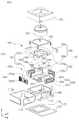
도 1은 본 발명의 제1 실시예에 따른 카메라 모듈의 사시도이다.
도 2는 본 발명의 제1 실시예에 따른 카메라 모듈의 개략 분해 사시도이다.
도 3은 본 발명의 제1 실시예에 따른 카메라 모듈에 구비되는 초점 조정 유닛을 나타내는 확대 분해 사시도이다.
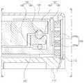
도 4는 도 1의 A-A'의 단면도이다.
도 5는 본 발명의 제1 실시예에 따른 카메라 모듈에 구비되는 흔들림 보정 유닛을 나타내는 확대 분해 사시도이다.
도 6은 본 발명의 제2 실시예에 따른 카메라 모듈을 나타내는 분해 사시도이다.
도 7은 본 발명의 제2 실시예에 따른 카메라 모듈의 단면도이다.1 is a perspective view of a camera module according to a first embodiment of the present invention.
2 is a schematic exploded perspective view of a camera module according to a first embodiment of the present invention.
3 is an enlarged exploded perspective view illustrating a focus adjustment unit included in the camera module according to the first embodiment of the present invention.
4 is a cross-sectional view taken along line AA ′ of FIG. 1.
5 is an enlarged exploded perspective view illustrating a shake correction unit included in the camera module according to the first embodiment of the present invention.
6 is an exploded perspective view showing a camera module according to a second embodiment of the present invention.
7 is a cross-sectional view of a camera module according to a second embodiment of the present invention.
이하, 첨부된 도면을 참조하여 본 발명의 바람직한 실시 형태들을 설명한다. 그러나, 본 발명의 실시형태는 여러 가지 다른 형태로 변형될 수 있으며, 본 발명의 범위가 이하 설명하는 실시 형태로 한정되는 것은 아니다. 또한, 본 발명의 실시형태는 당해 기술분야에서 평균적인 지식을 가진 자에게 본 발명을 더욱 완전하게 설명하기 위해서 제공되는 것이다. 도면에서 요소들의 형상 및 크기 등은 보다 명확한 설명을 위해 과장될 수 있다.Hereinafter, preferred embodiments of the present invention will be described with reference to the accompanying drawings. However, embodiments of the present invention may be modified in various other forms, and the scope of the present invention is not limited to the embodiments described below. In addition, the embodiments of the present invention are provided to more completely explain the present invention to those skilled in the art. Shape and size of the elements in the drawings may be exaggerated for more clear description.
본 발명은 렌즈 구동 장치 및 이를 포함하는 카메라 모듈에 관한 것으로서, 이동 통신 단말기, 스마트 폰, 태블릿 PC 등의 휴대가능한 전자 기기에 적용될 수 있다.The present invention relates to a lens driving apparatus and a camera module including the same, and may be applied to a portable electronic device such as a mobile communication terminal, a smart phone, a tablet PC, and the like.
카메라 모듈은 사진 또는 동영상 촬영을 위한 광학 기기로서, 피사체로부터 반사된 빛을 굴절시키는 렌즈 및 초점을 조정하거나 흔들림을 보정하기 위해 렌즈를 이동시키는 렌즈 구동 장치를 구비한다.The camera module is an optical device for photographing or moving picture, and includes a lens for refracting light reflected from a subject and a lens driving device for moving a lens to adjust focus or correct shake.
도 1은 본 발명의 제1 실시예에 따른 카메라 모듈의 사시도이고, 도 2는 본 발명의 제1 실시예에 따른 카메라 모듈의 개략 분해 사시도이다.1 is a perspective view of a camera module according to a first embodiment of the present invention, Figure 2 is a schematic exploded perspective view of the camera module according to a first embodiment of the present invention.
도 1 내지 도 2를 참조하면, 본 발명의 제1 실시예에 따른 카메라 모듈(100)은 하우징(110), 쉴드 케이스(120), 렌즈 배럴(130), 렌즈 구동 장치(140), 이미지 센서 유닛(170)을 포함하여 구성될 수 있다.1 to 2, the
하우징(110)은 내부에 렌즈 배럴(130)과 렌즈 구동 장치(140)가 수용될 수 있는 내부 공간을 가지도록 형성될 수 있다. 일예로서, 하우징(110)은 6면이 개방된 육면체 박스 형상을 가질 수 있다. 또한, 하우징(110)은 플라스틱 재질로 이루어질 수 있다. 일예로서, 하우징(110)의 저면은 이미지 센서 유닛(170)을 위해 개방될 수 있으며, 하우징(110)의 네 측면은 렌즈 구동 장치(140)의 설치를 위해 개방될 수 있다.The
쉴드 케이스(120)는 하우징(110)의 외부면을 감싸도록 하우징(110)과 결합되며, 카메라 모듈(100)의 내부 구성부품을 보호하는 기능을 수행한다. 또한, 쉴드 케이스(120)는 전자기파를 차폐하는 기능을 수행할 수 있다. 일예로서, 카메라 모듈(100)에서 발생된 전자파가 휴대가능한 전자기기 내의 다른 전자부품에 영향을 미치지 않도록 케이스(110)가 전자파를 차폐할 수 있다. 또한, 휴대가능한 전자기기에는 카메라 모듈(100) 이외에 여러 전자부품이 장착되므로, 이러한 전자부품에서 발생된 전자파가 카메라 모듈(100)에 영향을 미치지 않도록 쉴드 케이스(120)가 전자파를 차폐할 수 있다.The
쉴드 케이스(120)는 금속재질로 이루어지며, 후술할 이미지 센서 유닛(170)의 인쇄회로기판(174)에 구비되는 접지패드(미도시)에 접지될 수 있으며, 이에 따라 전자파를 차폐할 수 있다.The
다만, 이에 한정되지 않으며, 쉴드 케이스(120)는 플라스틱 사출물로 형성될 수도 있다. 이러한 경우 쉴드 케이스(120)의 내부면에 전도성 도료가 도포되거나, 전도성 필름 또는 전도성 테이프가 쉴드 케이스(120)의 내부면에 부착되어 전자파를 차폐할 수 있다. 이 때, 전도성 도료로는 전도성 에폭시가 사용될 수 있으나, 이에 한정되지 않으며 전도성을 가진 다양한 재료가 사용될 수 있다.However, the present invention is not limited thereto, and the
렌즈 배럴(130)은 피사체를 촬상하는 복수의 렌즈가 내부에 수용될 수 있도록 중공의 원통 형상일 수 있으며, 복수의 렌즈는 광축(Z축)을 따라 렌즈 배럴(130)에 장착된다.The
복수의 렌즈는 렌즈 배럴(130)의 설계에 따라 필요한 수만큼 배치되고, 각각의 렌즈는 동일하거나 상이한 굴절률 등의 광학적 특성을 가진다.A plurality of lenses are disposed as many as necessary according to the design of the
렌즈 구동 장치(140)는 렌즈 배럴(130)을 이동시키는 장치이다. 일예로서, 렌즈 구동 장치(140)는 렌즈 배럴(130)을 광축(Z축) 방향으로 이동시킴으로써 초점을 조정할 수 있고, 렌즈 배럴(130)을 광축(Z축)에 수직한 방향으로 이동시킴으로써 촬영 시의 흔들림을 보정할 수 있다.The
렌즈 구동 장치(140)는 초점을 조정하는 초점 조정 유닛(150) 및 흔들림을 보정하는 흔들림 보정 유닛(160)을 포함한다.The
한편, 초점 조정 유닛(150) 및 흔들림 보정 유닛(160)의 자세한 설명은 후술하기로 한다.Meanwhile, a detailed description of the
이미지 센서 유닛(170)은 렌즈 배럴(130)을 통해 입사된 광을 전기 신호로 변환하는 장치이다.The
일 예로, 이미지 센서 유닛(170)은 이미지 센서(172) 및 인쇄회로기판(174)을 포함하며, 적외선 필터(미도시)를 더 포함할 수 있다.For example, the
이미지 센서(172)는 인쇄회로기판(174)에 설치되며, 적외선 필터(미도시)는 렌즈 배럴(130)을 통해 입사된 광 중에서 적외선 영역의 광이 이미지 센서(172)로 유입되는 것을 차단하는 역할을 수행한다.The
이미지 센서(172)는 렌즈 배럴(130)을 통해 입사된 광을 전기 신호로 변환한다. 일예로서, 이미지 센서(172)는 CCD(Charge Coupled Device) 또는 CMOS(Complementary Metal-Oxide Semiconductor)일 수 있다.The
이미지 센서(172)에 의해 변환된 전기 신호는 휴대가능한 전자기기의 디스플레이 유닛을 통해 영상으로 출력된다.The electrical signal converted by the
이미지 센서(172)는 인쇄회로기판(174)에 고정되며, 와이어 본딩에 의하여 인쇄회로기판(174)과 전기적으로 연결된다.The
이하에서는 도면을 참조하여 렌즈 구동 장치에 대하여 보다 자세하게 살펴보기로 한다.Hereinafter, the lens driving apparatus will be described in more detail with reference to the accompanying drawings.
도 3은 본 발명의 제1 실시예에 따른 카메라 모듈에 구비되는 초점 조정 유닛을 나타내는 확대 분해 사시도이고, 도 4는 도 1의 A-A'의 단면도이다.3 is an enlarged exploded perspective view illustrating a focus adjusting unit included in the camera module according to the first embodiment of the present invention, and FIG. 4 is a cross-sectional view taken along line AA ′ of FIG. 1.
도 3 및 도 4를 참조하면, 렌즈 구동 장치(140, 도 2 참조)는 피사체에 초점을 맞추기 위하여 렌즈 배럴(130, 도 2 참조)을 이동시킨다.3 and 4, the lens driving device 140 (see FIG. 2) moves the lens barrel 130 (see FIG. 2) to focus on a subject.
일 예로, 본 발명은 렌즈 배럴(130)을 광축(Z축) 방향으로 이동시키는 초점 조정 유닛(150)을 구비한다.As an example, the present invention includes a
초점 조정 유닛(150)은, 렌즈 배럴(130)을 수용하는 캐리어(151) 및 렌즈 배럴(130)과 캐리어(151)를 광축(Z축) 방향으로 이동시키도록 구동력을 발생시키는 초점 조정 구동부(152)를 포함한다.The
초점 조정 구동부(152)는 캐리어(151)와 하우징(110) 중 어느 하나에 설치되는 초점 조정용 마그네트(153) 및 초점 조정용 마그네트(153)에 대향 배치되는 초점 조정용 코일(154)을 포함한다.The
초점 조정용 마그네트(153)는 캐리어(151)에 장착된다. 일 예로서, 초점 조정용 마그네트(153)는 캐리어(151)의 일면에 장착될 수 있다.The focus adjusting
초점 조정용 코일(154)은 하우징(110)에 장착된다. 일 예로서, 초점 조정용 코일(154)은 기판(112)을 매개로 하우징(110)에 장착될 수 있다.The
초점 조정용 마그네트(153)는 캐리어(151)에 장착되어 캐리어(151)와 함께 광축(Z축) 방향으로 이동하는 이동부재이고, 초점 조정용 코일(154)은 하우징(110)에 고정된 고정부재이다. 다만, 이에 한정되지 않으며, 초점 조정용 마그네트(153)와 초점 조정용 코일(154)의 설치 위치를 서로 바꾸는 것도 가능하다.The focusing
한편, 초점 조정용 코일(154)에 전원이 인가되면, 초점 조정용 마그네트(153)와 초점 조정용 코일(154) 사이의 전자기적 영향력에 의하여 캐리어(151)를 광축(Z축) 방향으로 이동시킬 수 있다.On the other hand, when power is applied to the focusing
캐리어(151)에는 렌즈 배럴(130)이 수용되므로, 캐리어(151)의 이동에 의해 렌즈 배럴(130)도 광축(Z축) 방향으로 이동된다.Since the
캐리어(151)가 이동될 때, 캐리어(151)와 하우징(110) 사이의 마찰을 저감하도록 캐리어(151)와 하우징(110) 사이에 구름부재(180)가 배치된다. 구름부재(180)는 볼 형태일 수 있다.When the
한편, 구름부재(180)는 초점 조정용 마그네트(153)의 양측에 배치된다. 일예로서, 구름부개(102)는 복수개가 초점 조정용 마그네트(153)의 양측에 각각 하나의 열을 이루도록 배치될 수 있다.On the other hand, the rolling
하우징(110)에는 초점 조정용 요크(114)가 배치된다. 일예로서, 초점 조정용 요크(114)는 초점 조정용 코일(154)을 사이에 두고 초점 조정용 마그네트(153)와 마주보도록 배치된다.The focusing
초점 조정용 요크(114)와 초점 조정용 마그네트(153) 사이에는 광축(Z축)에 수직한 방향으로 인력이 작용한다. 따라서, 초점 조정용 요크(114)와 초점 조정용 마그네트(153) 사이의 인력에 의해 구름부재(180)는 캐리어(151) 및 하우징(110)과 접촉 상태를 유지할 수 있다.An attractive force acts between the
또한, 초점 조정용 요크(114)는 초점 조정용 마그네트(153)의 자기력이 집속되도록 하는 기능도 한다. 이에 따라, 누설 자속이 발생하는 것을 저감시킬 수 있다. 일예로, 초점 조정용 요크(114)와 초점 조정용 마그네트(153)는 자기 회로(Magnetic circuit)를 형성한다. 이때, 초점 조점용 요크(155)의 광축(Z축) 방향 길이는 초점 조정용 마그네트(153)의 광축(Z축) 방향 길이보다 길게 형성될 수 있다.In addition, the focusing
초점 조정용 유닛(150)은 초점 조정용 마그네트(153)와 초점 조정용 코일(154)이 설치되는 면을 제외한 영역에 배치되는 초점 조정 센싱부(155)를 더 포함한다. 초점 조정 센싱부(155)는 일예로서, 하우징(110)의 상단부에 배치되는 제1 초점 조정 센싱부(156)와, 제1 초점 조정 센싱부(156)의 하부에 이격 배치되는 제2 초점 조정 센싱부(157)를 구비한다. 나아가, 제1 초점 조정 센싱부(156)와 제2 초점 조정 센싱부(157)의 사이에는 도 3에 보다 자세하게 도시된 바와 같이 후술할 흔들림 보정 유닛(160)에 구비되는 볼 부재(180)가 배치될 수 있다.The
그리고, 제1 초점 조정 센싱부(156)는 하우징(110)의 상단부에 설치되는 제1 초점 조정 센싱용 요크(156a) 및 제1 초점 조정 센싱용 요크(156a)에 대향 배치되는 제1 초점 조정 센싱용 코일(156b)을 구비한다.In addition, the first focusing
나아가, 제2 초점 조정 센싱부(157)는 하우징(110)의 하단부에 설치되는 제2 초점 조정 센싱용 요크(157a) 및 제2 초점 조정 센싱용 요크(157a)에 대향 배치되는 제2 초점 조정 센싱용 코일(157b)을 구비한다.In addition, the second focusing
더하여, 제2 초점 조정 센싱부(157)는 초점 조정용 코일(154)이 연결되는 기판(112)에 연결되는 연결기판(157c)을 더 구비할 수 있다. 또한, 제1 초점 조정 센싱부(156)는 기판(112)의 연결부(112a)에 연결될 수 있다.In addition, the second
한편, 제1 초점 조정 센싱부(156)와 제2 초점 조정 센싱부(157)는 설치되는 위치에서만 차이가 있으므로, 이하에서는 제1 초점 조정 센싱부(156)에 대해서만 설명하고 제2 초점 조정 센싱부(157)에 대한 자세한 설명을 생략하기로 한다.On the other hand, since the first focusing
제1 초점 조정 센싱용 코일(156b)은 적어도 두 개 이상의 코일로 구성될 수 있다. 제1 초점 조정 센싱용 코일(156b)의 인덕턴스는 제1 초점 조정 센싱용 요크(157a)의 변위에 따라 변경될 수 있다.The first focusing
한편, 본 발명은 렌즈 배럴(130)의 위치를 감지하여 피드백하는 폐루프 제어 방식을 사용한다. 따라서, 폐루프 제어를 위하여 초점 조정 센싱부(155)가 구비된다.On the other hand, the present invention uses a closed loop control method for sensing and feeding back the position of the
폐루프 제어에 대하여 보다 자세하게 살펴보면, 카메라 모듈(100)의 전원이 켜지면, 초점 조정 센싱부(155)에 의해 렌즈 배럴(130)의 초기 위치가 감지된다. 그리고, 렌즈 배럴(130)은 감지된 초기 위치로부터 초기 설정 위치로 이동된다. 여기서, 초기 위치는 카메라 모듈(100)의 전원이 켜졌을 때 렌즈 배럴(130)의 광축 방향으로의 위치를 의미할 수 있고, 초기 설정위치는 렌즈 배럴(130)의 초점이 무한대가 되는 위치를 의미할 수 있다.Looking at the closed loop control in more detail, when the power of the
렌즈 배럴(130)은 회로소자의 구동신호에 의해 초기 설정위치로부터 목표 위치까지 이동된다.The
초점 조정 과정에서 렌즈 배럴(130)은 광축(Z축) 방향으로 전진 및 후진이 가능하다(즉, 양방향 이동이 가능하다).In the focusing process, the
이와 같이, 초점 조정 센싱부(155)가 초점 조정용 마그네트(153)와 초점 조정용 코일(154)이 설치되는 면을 제외한 영역에 설치됨으로써 초점 조정용 마그네트(153)와 초점 조정용 코일(154)의 크기를 증가시킬 수 있다.As described above, the focusing
다시 말해, 초점 조정 센싱부(155)가 초점 조정용 마그네트(153)와 초점 조정용 코일(154)이 설치되는 면을 제외한 영역에 설치됨으로써 초점 조정용 마그네트(153)와 초점 조정용 코일(154)의 크기를 하우징(110)의 일 측면 전체에 대응되도록 증가시킬 수 있다.In other words, the focusing
이에 따라, 초점 조정을 위한 구동력, 즉 초점 조정용 유닛(150)에 의해 발생되는 구동력을 증대시킬 수 있는 것이다.Accordingly, the driving force for focusing, that is, the driving force generated by the focusing
도 5는 본 발명의 제1 실시예에 따른 카메라 모듈에 구비되는 흔들림 보정 유닛을 나타내는 확대 분해 사시도이다.5 is an enlarged exploded perspective view illustrating a shake correction unit included in the camera module according to the first embodiment of the present invention.
흔들림 보정 유닛(160)은 이미지 촬영 또는 동영상 촬영 시 사용자의 손떨림 등의 요인에 의해 이미지가 번지거나 동영상이 흔들리는 것을 보정하기 위해 사용된다.The
예를 들어, 흔들림 보정 유닛(160)은 사용자의 손떨림 등에 의해 영상 촬영 시 흔들림이 발생할 때, 흔들림에 대응하는 상대변위를 렌즈 배럴(130)에 부여함으로써 흔들림을 보상한다.For example, the
일예로서, 흔들림 보정 유닛(160)은 렌즈 배럴(130)을 광축(Z축)에 수직한 방향으로 이동시켜 흔들림을 보정한다.As an example, the
도 5를 참조하면, 흔들림 보정 유닛(160)은 렌즈 배럴(130)의 이동을 가이드하는 가이드부재(161) 및 가이드부재(161)를 광축(Z축)에 수직한 방향으로 이동시키도록 구동력을 발생시키는 흔들림 보정 구동부(164)를 포함한다.Referring to FIG. 5, the
가이드부재(161)는 프레임(162) 및 렌즈 홀더(163)를 포함한다. 프레임(162)과 렌즈 홀더(163)는 캐리어(151) 내에 삽입되어 광축(Z축) 방향으로 배치되며, 렌즈 배럴(130)의 이동을 가이드하는 기능을 한다.The
프레임(162)과 렌즈 홀더(163)는 렌즈 배럴(130)이 삽입될 수 있는 공간을 구비한다. 렌즈 배럴(130)은 렌즈 홀더(163)에 고정된다.The
흔들림 보정 구동부(164)에서 발생된 구동력에 의하여 프레임(162) 및 렌즈 홀더(163)는 캐리어(151) 내에서 광축(Z축)에 수직한 방향으로 이동된다.The
흔들림 보정 구동부(164)는 광축(Z축) 대하여 수직한 제1 축(X축) 방향으로 구동력을 발생시키는 제1 흔들림 보정 구동부(165)와, 광축(Z축) 및 제1 축(X축)에 모두 수직인 제2 축(Y축) 방향으로 구동력을 발생시키는 제2 흔들림 보정 구동부(166)를 구비한다.The
제1 흔들림 보정 구동부(165)는 광축(Z축)에 수직한 제1 축(X축) 방향으로 구동력을 발생시키고, 제2 흔들림 보정 구동부(166)는 제1 축(X축)에 수직한 제2 축(Y축) 방향으로 구동력을 발생시킨다.The first
여기서, 제2 축(Y축)은 광축(Z축)과 제1 축(X축)에 모두 수직한 축을 의미한다.Here, the second axis (Y axis) means an axis perpendicular to both the optical axis (Z axis) and the first axis (X axis).
제1 흔들림 보정 구동부(165)와 제2 흔들림 보정 구동부(166)는 광축(Z축)에 수직한 평면에서 서로 직교하도록 배치된다. 일예로서, 제1 흔들림 보정 구동부(165)와 제2 흔들림 보정 구동부(166)는 광축(Z축)에 수직한 평면에서 서로 직교하도록 배치된다.The first
일예로서, 제1 흔들림 보정 구동부(165)는 프레임(162) 및 하우징(110) 중 어느 하나에 설치되는 제1 흔들림 보정용 마그네트(165a)와, 제1 흔들림 보정용 마그네트(165a)에 대향 배치되는 제1 흔들림 보정용 코일(165b)을 구비한다.For example, the first
제2 흔들림 보정 구동부(166)는 프레임(162) 및 하우징(110) 중 어느 하나에 설치되는 제2 흔들림 보정용 마그네트(166a)와, 제2 흔들림 보정용 마그네트(166a)에 대향 배치되는 제2 흔들림 보정용 코일(166b)을 구비한다.The second shake
한편, 제1,2 흔들림 보정용 마그네트(165a,166a)는 렌즈 홀더(163)에 장착되고, 제1,2 흔들림 보정용 마그네트(165a,166a)에 대향 배치되는 제1,2 흔들림 보정용 코일(165b,166b)은 하우징(110)에 장착된다. 일예로서, 제1,2 흔들림 보정용 코일(165b,166b)은 기판(112)을 매개로 하우징(110)에 장착된다.On the other hand, the first and second
제1,2 흔들림 보정용 마그네트(165a,166a)는 렌즈 홀더(163)와 함께 광축(Z축)에 수직한 방향으로 이동되는 이동부재이고, 제1,2 흔들림 보정용 코일(165b,166b)은 하우징(110)에 고정된 고정부재이다. 다만, 이에 한정되는 것은 아니고, 제1,2 흔들림 보정용 마그네트(165a,166a)과 제1,2 흔들림 보정용 코일(165b,166b)의 위치를 서로 바꾸는 것도 가능하다.The first and second
흔들림 보정용 유닛(160)은 렌즈 홀더(163)에 설치되는 흔들림 보정 센싱용 요크(168) 및 흔들림 보정 센싱용 요크(168)에 대향 배치되는 흔들림 보정 센싱용 코일(169)을 구비하는 흔들림 보정 센싱용 센서부(167)를 더 구비한다.The
일예로서, 흔들림 보정 센싱용 센서부(167)는 초점 조정용 마그네트(153)가 설치되는 캐리어(151)의 일면에 직교하는 면에 배치될 수 있다.As an example, the shake correction
한편, 흔들림 보정 센싱용 코일(169)은 기판(112)을 매개로 하우징(110)에 장착된다. 즉, 흔들림 보정 센싱용 코일(169)은 고정부재이고, 흔들림 보정 센싱용 요크(168)는 이동부재이다.On the other hand, the shake
본 발명의 렌즈 구동 장치(140)는 흔들림 보정 과정에서 렌즈 배럴(130)의 위치를 감지하여 피드백하는 폐루프 제어 방식을 사용한다. 이를 위해, 상기한 흔들림 보정 센싱용 센서부(167)가 구비된다.The
폐루프 제어에 대하여 보다 자세하게 살펴보면, 카메라 모듈(100)의 전원이 켜지면, 흔들림 보정 센싱용 센서부(167)에 의해 렌즈 배럴(130)의 초기 위치가 감지된다. 그리고, 렌즈 배럴(130)은 감지된 초기 위치로부터 초기 설정 위치로 이동된다. 여기서, 설정위치는 제1 축(X축) 방향으로의 이동 가능 범위의 중앙과 제2 축(Y축) 방향으로의 이동 가능 범위의 중앙을 의미할 수 있다. 기구적으로는, 흔들림 보정용 유닛(160)이 수용되는 캐리어(151)의 제1 축(X축) 방향으로의 중앙과 제2 축(Y축) 방향으로의 중앙을 의미할 수 있다.Looking at the closed loop control in more detail, when the power of the
한편, 본 발명에는 흔들림 보정 유닛(1600)을 지지하는 복수의 볼 부재(181)가 제공된다. 복수의 볼 부재(181)는 흔들림 보정 과정에서 프레임(162) 및 렌즈 홀더(163)를 가이드하는 기능을 한다. 또한, 캐리어(151), 프레임(162) 및 렌즈 홀더(163) 간의 간격을 유지시키는 기능도 한다.On the other hand, the present invention is provided with a plurality of
복수의 볼 부재(181)는 제1 볼 부재(182) 및 제2 볼 부재(184)를 포함한다.The plurality of
제1 볼 부재(182)는 흔들림 보정 유닛(160)의 제1 축(X축) 방향으로의 이동을 가이드하고, 제2 볼 부재(184)는 흔들림 보정 유닛(160)의 제2 축(Y축) 방향으로의 이동을 가이드한다.The
일 예로, 제1 볼 부재(182)는 제1 축(X축) 방향으로의 구동력이 발생한 경우에 제1 축(X축) 방향으로 구름운동한다. 이에 따라, 제1 볼 부재(182)는 프레임(162)과 렌즈 홀더(163)의 제1 축(X축) 방향으로의 이동을 가이드한다.For example, when the driving force in the first axis (X axis) direction occurs, the
또한, 제2 볼 부재(184)는 제2 축(Y축) 방향으로의 구동력이 발생한 경우에 제2 축(Y축) 방향으로 구름운동한다. 이에 따라, 제2 볼 부재(184)는 렌즈 홀더(163)의 제2 축(Y축) 방향으로의 이동을 가이드한다.In addition, when the driving force in the second axis (Y axis) direction occurs, the
제1 볼 부재(182)는 캐리어(151)와 프레임(162) 사이에 배치되는 복수의 볼 부재를 포함하고, 제2 볼 부재(184)는 프레임(162)과 렌즈 홀더(163) 사이에 배치되는 복수의 볼 부재를 포함한다.The
한편, 본 발명에서는 외부 충격 등에 의하여 복수의 볼 부재(181), 프레임(162) 및 렌즈 홀더(163)가 캐리어(151)의 외부로 이탈되는 것을 방지하도록 스토퍼(190)가 제공된다(도 2 참고).On the other hand, in the present invention, the
상기한 바와 같이, 초점 조정 센싱부(155)가 초점 조정용 마그네트(153)와 초점 조정용 코일(154)이 설치되는 면을 제외한 영역에 설치됨으로써 초점 조정용 마그네트(153)와 초점 조정용 코일(154)의 크기를 증가시킬 수 있다.As described above, the focusing
이에 따라, 초점 조정을 위한 구동력, 즉 초점 조정용 유닛(150)에 의해 발생되는 구동력을 증대시킬 수 있는 것이다.Accordingly, the driving force for focusing, that is, the driving force generated by the focusing
이하에서는 도면을 참조하여 본 발명의 제2 실시예에 따른 카메라 모듈에 대하여 설명하기로 한다.Hereinafter, a camera module according to a second embodiment of the present invention will be described with reference to the drawings.
도 6은 본 발명의 제2 실시예에 따른 카메라 모듈을 나타내는 분해 사시도이고, 도 7은 본 발명의 제2 실시예에 따른 카메라 모듈의 단면도이다.6 is an exploded perspective view showing a camera module according to a second embodiment of the present invention, Figure 7 is a cross-sectional view of the camera module according to a second embodiment of the present invention.
한편, 도 7은 본 발명의 제2 실시예에 따른 카메라 모듈에 구비되는 초점 조정 센싱부의 설치 위치를 설명하기 위한 단면도이다.On the other hand, Figure 7 is a cross-sectional view for explaining the installation position of the focus adjustment sensing unit provided in the camera module according to the second embodiment of the present invention.
도 6 및 도 7을 참조하면, 본 발명의 제2 실시예에 따른 카메라 모듈(200)은 하우징(110), 쉴드 케이스(120), 렌즈 배럴(130), 렌즈 구동 장치(240), 이미지 센서 유닛(170)을 포함하여 구성될 수 있다.6 and 7, the
한편, 하우징(110), 쉴드 케이스(120), 렌즈 배럴(130) 및 이미지 센서 유닛(170)은 상기에서 설명한 구성요소와 실질적으로 동일하므로 자세한 설명은 생략하고 상기한 설명에 갈음하기로 한다.Meanwhile, since the
또한, 렌즈 구동 장치(240)는 렌즈 배럴(130)을 이동시키는 장치이다. 일예로서, 렌즈 구동 장치(240)는 렌즈 배럴(130)을 광축(Z축) 방향으로 이동시킴으로써 초점을 조정할 수 있고, 렌즈 배럴(130)을 광축(Z축)에 수직한 방향으로 이동시킴으로써 촬영 시의 흔들림을 보정할 수 있다.In addition, the
렌즈 구동 장치(240)는 초점을 조정하는 초점 조정 유닛(250) 및 흔들림을 보정하는 흔들림 보정 유닛(160)을 포함한다.The
한편, 흔들림 보정 유닛(160)은 상기에서 설명한 구성요소와 실질적으로 동일하므로 자세한 설명은 생략하고 상기한 설명에 갈음하기로 한다.On the other hand, since the
나아가, 초점 조정 유닛(250)은 초점 조정 센싱부(255)를 제외하고는 상기에서 설명한 구성과 동일하므로 여기서는 자세한 설명을 생략하고 상기한 설명에 갈음하기로 한다.In addition, since the
초점 조정 센싱부(255)는 캐리어(251)에 고정 설치되는 초점 조정 센싱용 요크(255a) 및 초점 조정 센싱용 요크(255a)에 대향 배치되는 초점 조정 센싱용 코일(255b)을 구비한다.The focus
초점 조정 센싱부(255)는 초점 조정용 마그네트(253)와 초점 조정용 코일(254)이 설치되는 면에 직교하는 면에 배치된다. 일예로서, 흔들림 보정 유닛(160)의 흔들림 보정 센싱용 센서부(167)와 초점 조정 유닛(250)의 초점 조정 센싱부(255)는 나란히 배치된다.The focus
일예로서, 초점 조정 센싱용 요크(255a)는 캐리어(251)에 설치되며, 흔들림 보정 센싱용 요크(167a)는 프레임(162)에 설치될 수 있다. 또한, 초점 조정 센싱용 코일(255b)과 흔들림 보정 센싱용 코일(167b)은 기판(112)을 매개로 하여 하우징(110)에 고정 설치될 수 있다.For example, the focusing
상기한 바와 같이, 초점 조정 센싱부(255)가 초점 조정용 마그네트(253)와 초점 조정용 코일(254)이 설치되는 면을 제외한 영역에 설치됨으로써 초점 조정용 마그네트(253)와 초점 조정용 코일(254)의 크기를 증가시킬 수 있다.As described above, the focusing
이에 따라, 초점 조정을 위한 구동력, 즉 초점 조정용 유닛(250)에 의해 발생되는 구동력을 증대시킬 수 있는 것이다.Accordingly, the driving force for focusing, that is, the driving force generated by the focusing
이상에서 본 발명의 실시예에 대하여 상세하게 설명하였지만 본 발명의 권리범위는 이에 한정되는 것은 아니고, 청구범위에 기재된 본 발명의 기술적 사상을 벗어나지 않는 범위 내에서 다양한 수정 및 변형이 가능하다는 것은 당 기술분야의 통상의 지식을 가진 자에게는 자명할 것이다.Although the embodiments of the present invention have been described in detail above, the scope of the present invention is not limited thereto, and various modifications and changes can be made without departing from the technical spirit of the present invention described in the claims. It will be obvious to those of ordinary skill in the field.
100, 200 : 카메라 모듈
110 : 하우징
120 : 쉴드 케이스
130 : 렌즈 모듈
140, 240 : 렌즈 구동 장치
150, 250 : 초점 조정 유닛
160 : 혼들림 보정 유닛
170 : 이미지 센서 유닛100, 200: camera module
110: housing
120: shield case
130: lens module
140, 240: lens driving device
150, 250: focusing unit
160: blending correction unit
170: image sensor unit
Claims (16)
Translated fromKorean상기 렌즈 배럴을 광축 방향으로 이동시키는 초점 조정 유닛 및 상기 렌즈 배럴을 광축 방향에 수직인 방향으로 이동시키는 흔들림 보정 유닛을 구비하는 렌즈 구동 장치;
상기 렌즈 배럴과 상기 렌즈 구동 장치를 수용하는 하우징;
을 포함하며,
상기 초점 조정 유닛은 상기 렌즈 배럴을 수용하는 캐리어와, 상기 캐리어와 상기 하우징 중 어느 하나에 설치되는 초점 조정용 마그네트 및 상기 초점 조정용 마그네트에 대향 배치되는 초점 조정용 코일을 구비하며,
상기 초점 조정 유닛은 초점 조정 센싱용 요크 및 상기 초점 조정 센싱용 요크에 대향 배치되는 초점 조정 센싱용 코일을 구비하는 초점 조정 센싱부를 더 구비하고,
상기 초점 조정 센싱부는 상기 초점 조정용 마그네트와 상기 초점 조정용 코일 및 상기 흔들림 보정 유닛이 배치되는 상기 캐리어의 측면을 제외한 영역에 배치되는 카메라 모듈.
Lens barrels;
A lens driving device having a focus adjusting unit for moving the lens barrel in an optical axis direction and a shake correction unit for moving the lens barrel in a direction perpendicular to the optical axis direction;
A housing accommodating the lens barrel and the lens driving device;
Including;
The focusing unit includes a carrier for accommodating the lens barrel, a focusing magnet installed on any one of the carrier and the housing, and a focusing coil disposed opposite to the focusing magnet,
The focusing unit further includes a focusing sensing unit having a focusing sensing yoke and a focusing sensing coil disposed opposite to the focusing sensing yoke,
The focus adjustment sensing unit is disposed in an area excluding a side of the carrier on which the focus adjustment magnet, the focus adjustment coil, and the shake correction unit are disposed.
상기 초점 조정 센싱부는 상기 초점 조정용 마그네트와 상기 초점 조정용 코일이 설치되는 면에 직교하는 면에 배치되는 카메라 모듈.
The method of claim 1,
The focus adjusting sensing unit is disposed on a surface orthogonal to the surface on which the focus adjusting magnet and the focus adjusting coil are installed.
상기 흔들림 보정 유닛은 흔들림 보정 센싱용 요크 및 상기 흔들림 보정 센싱용 요크에 대향 배치되는 흔들림 보정 센싱용 코일을 구비하는 흔들림 보정 센싱부를 구비하는 카메라 모듈.
The method of claim 2,
The shake correction unit includes a shake correction sensing unit having a shake correction sensing yoke and a shake correction sensing coil disposed to face the shake correction sensing yoke.
상기 초점 조정 센싱부는 상기 흔들림 보정 센싱부와 나란히 배치되는 카메라 모듈.
The method of claim 3, wherein
The focus adjustment sensing unit is disposed in parallel with the shake correction sensing unit.
상기 초점 조정 센싱부에 구비되는 초점 조정 센싱용 코일은 적어도 두 개 이상의 코일부를 가지는 카메라 모듈.
The method of claim 4, wherein
The focusing sensing coil provided in the focusing sensing unit has at least two coil units.
상기 초점 조정 센싱부의 상기 초점 조정 센싱용 요크와 상기 초점 조정 센싱용 코일은 광축 방향으로 상호 대향 배치되는 카메라 모듈.
The method of claim 1,
And the focus adjusting sensing yoke and the focusing sensing coil are disposed to face each other in an optical axis direction.
상기 초점 조정 센싱부는 상기 하우징의 상단부에 배치되는 제1 초점 조정 센싱부와, 상기 제1 초점 조정 센싱부의 하부에 이격 배치되는 제2 초점 조정 센싱부를 구비하는 카메라 모듈.
The method of claim 6,
The focus adjusting sensing unit includes a first focusing sensing unit disposed at an upper end of the housing, and a second focusing sensing unit spaced apart from the lower portion of the first focusing sensing unit.
상기 제1 초점 조정 센싱부와 상기 제2 초점 조정 센싱부 사이에는 볼 부재가 배치되는 카메라 모듈.
The method of claim 7, wherein
And a ball member disposed between the first focusing sensor and the second focusing sensor.
상기 초점 조정 센싱부는 상기 초점 조정용 코일이 연결되는 기판에 연결되는 연결기판을 더 구비하는 카메라 모듈.
The method of claim 6,
The focus adjustment sensing unit further comprises a connection substrate connected to a substrate to which the focus adjustment coil is connected.
상기 흔들림 보정 유닛은 상기 렌즈 배럴의 이동을 가이드하는 가이드부재 및 상기 가이드부재를 광축에 수직한 방향으로 이동시키도록 구동력을 발생시키는 흔들림 보정 구동부를 구비하는 카메라 모듈.
The method of claim 1,
The shake correction unit includes a guide member for guiding the movement of the lens barrel and a shake correction driver for generating a driving force to move the guide member in a direction perpendicular to the optical axis.
상기 가이드부재는 상기 캐리어 내에 삽입되어 설치되는 프레임과, 상기 렌즈 배럴이 설치되는 렌즈 홀더를 구비하는 카메라 모듈.
The method of claim 10,
The guide member includes a frame inserted into the carrier and a lens holder including the lens barrel is installed.
상기 흔들림 보정 구동부는 상기 광축에 대하여 수직한 제1 축 방향으로 구동력을 발생시키는 제1 흔들림 보정 구동부와, 상기 광축 및 상기 제1 축에 모두 수직인 제2 축 방향으로 구동력을 발생시키는 제2 흔들림 보정 구동부를 구비하는 카메라 모듈.
The method of claim 11,
The shake correction driver includes a first shake correction driver that generates a driving force in a first axis direction perpendicular to the optical axis, and a second shake that generates driving force in a second axis direction perpendicular to both the optical axis and the first axis. Camera module having a correction drive.
상기 제1 흔들림 보정 구동부는 상기 프레임 및 상기 하우징 중 어느 하나에 설치되는 제1 흔들림 보정용 마그네트와, 상기 제1 흔들림 보정용 마그네트에 대향 배치되는 제1 흔들림 보정용 코일을 구비하는 카메라 모듈.
The method of claim 12,
The first shake correction driving unit includes a first shake correction magnet installed in one of the frame and the housing, and a first shake correction coil disposed opposite to the first shake correction magnet.
상기 제2 흔들림 보정 구동부는 상기 프레임 및 상기 하우징 중 어느 하나에 설치되는 제2 흔들림 보정용 마그네트와, 상기 제2 흔들림 보정용 마그네트에 대향 배치되는 제2 흔들림 보정용 코일을 구비하는 카메라 모듈.
The method of claim 12,
The second shake correction driving unit includes a second shake correction magnet installed on one of the frame and the housing, and a second shake correction coil disposed to face the second shake correction magnet.
상기 흔들림 보정 유닛은 상기 프레임 및 상기 렌즈 홀더를 가이드하는 복수개의 볼 부재를 더 구비하는 카메라 모듈.
The method of claim 11,
The shake correction unit further comprises a plurality of ball members for guiding the frame and the lens holder.
상기 렌즈 배럴을 광축 방향에 수직인 방향으로 이동시키는 흔들림 보정 유닛;
을 포함하며,
상기 초점 조정 유닛은 상기 렌즈 배럴을 수용하는 캐리어와, 상기 캐리어를 수용하는 하우징과 상기 캐리어 중 어느 하나에 설치되는 초점 조정용 마그네트 및 상기 초점 조정용 마그네트에 대향 배치되는 초점 조정용 코일을 구비하며,
상기 초점 조정 유닛은 초점 조정 센싱용 요크 및 상기 초점 조정 센싱용 요크에 대향 배치되는 초점 조정 센싱용 코일을 구비하는 초점 조정 센싱부를 더 구비하고,
상기 초점 조정 센싱부는 상기 초점 조정용 마그네트와 상기 초점 조정용 코일 및 상기 흔들림 보정 유닛이 배치되는 상기 캐리어의 측면을 제외한 영역에 배치되는 렌즈 구동 장치.
A focus adjusting unit which moves the lens barrel in the optical axis direction; And
A shake correction unit for moving the lens barrel in a direction perpendicular to the optical axis direction;
Including;
The focusing unit includes a carrier for accommodating the lens barrel, a focusing magnet installed on any one of the housing and the carrier accommodating the carrier, and a focusing coil disposed opposite to the focusing magnet,
The focusing unit further includes a focusing sensing unit having a focusing sensing yoke and a focusing sensing coil disposed opposite to the focusing sensing yoke,
And the focus adjustment sensing unit is disposed in an area excluding a side of the carrier on which the focus adjustment magnet, the focus adjustment coil, and the shake correction unit are disposed.
Priority Applications (4)
| Application Number | Priority Date | Filing Date | Title |
|---|---|---|---|
| KR1020170073250AKR102029532B1 (en) | 2017-06-12 | 2017-06-12 | Lens driving apparatus and camera module including the same |
| US15/849,756US10422974B2 (en) | 2017-06-12 | 2017-12-21 | Lens driving device and camera module including the same |
| CN201810183043.6ACN109031584B (en) | 2017-06-12 | 2018-03-06 | Lens driving device and camera module including the same |
| CN201820308728.4UCN208421373U (en) | 2017-06-12 | 2018-03-06 | Camera model and lens driving apparatus |
Applications Claiming Priority (1)
| Application Number | Priority Date | Filing Date | Title |
|---|---|---|---|
| KR1020170073250AKR102029532B1 (en) | 2017-06-12 | 2017-06-12 | Lens driving apparatus and camera module including the same |
Publications (2)
| Publication Number | Publication Date |
|---|---|
| KR20180135299A KR20180135299A (en) | 2018-12-20 |
| KR102029532B1true KR102029532B1 (en) | 2019-10-07 |
Family
ID=64563516
Family Applications (1)
| Application Number | Title | Priority Date | Filing Date |
|---|---|---|---|
| KR1020170073250AActiveKR102029532B1 (en) | 2017-06-12 | 2017-06-12 | Lens driving apparatus and camera module including the same |
Country Status (3)
| Country | Link |
|---|---|
| US (1) | US10422974B2 (en) |
| KR (1) | KR102029532B1 (en) |
| CN (2) | CN109031584B (en) |
Cited By (1)
| Publication number | Priority date | Publication date | Assignee | Title |
|---|---|---|---|---|
| WO2022225344A1 (en)* | 2021-04-23 | 2022-10-27 | 삼성전자 주식회사 | Image stabilizer and electronic device comprising same |
Families Citing this family (23)
| Publication number | Priority date | Publication date | Assignee | Title |
|---|---|---|---|---|
| KR102029532B1 (en)* | 2017-06-12 | 2019-10-07 | 삼성전기주식회사 | Lens driving apparatus and camera module including the same |
| WO2018229865A1 (en)* | 2017-06-13 | 2018-12-20 | オリンパス株式会社 | Optical unit and endoscope |
| KR102538913B1 (en)* | 2018-08-13 | 2023-06-01 | 삼성전기주식회사 | Camera module |
| CN109560681A (en)* | 2018-12-29 | 2019-04-02 | 宜兴市贵鑫磁电高科技有限公司 | A kind of closed loop voice coil motor of mobile phone camera module three-winding |
| KR102632362B1 (en)* | 2019-02-21 | 2024-02-02 | 삼성전기주식회사 | Camera module |
| CN113711579B (en)* | 2019-03-26 | 2024-09-24 | Lg伊诺特有限公司 | Lens driving device, camera module and optical device including the same |
| US11513308B2 (en)* | 2019-04-01 | 2022-11-29 | Samsung Electro-Mechanics Co., Ltd. | Camera module |
| JP7451119B2 (en)* | 2019-09-19 | 2024-03-18 | キヤノン株式会社 | Imaging device |
| US11733538B2 (en)* | 2019-12-10 | 2023-08-22 | Samsung Electro-Mechanics Co., Ltd. | Camera module |
| KR102272591B1 (en)* | 2019-12-10 | 2021-07-05 | 삼성전기주식회사 | Camera module |
| WO2021134332A1 (en)* | 2019-12-30 | 2021-07-08 | 诚瑞光学(常州)股份有限公司 | Lens driving device |
| KR102279920B1 (en)* | 2020-02-10 | 2021-07-22 | 삼성전기주식회사 | Camera Module |
| KR102473415B1 (en)* | 2020-03-19 | 2022-12-02 | 삼성전기주식회사 | Camera Module |
| JP7104365B2 (en)* | 2020-03-30 | 2022-07-21 | ミツミ電機株式会社 | Optical element drive device, camera module, and camera mount device |
| KR102356804B1 (en)* | 2020-04-23 | 2022-01-28 | 삼성전기주식회사 | Camera Module |
| TWI755136B (en) | 2020-08-07 | 2022-02-11 | 大陽科技股份有限公司 | Driving module, camera module and electronic device |
| KR102369442B1 (en)* | 2020-09-02 | 2022-03-03 | 삼성전기주식회사 | Camera Module |
| KR102439902B1 (en)* | 2020-09-25 | 2022-09-05 | 삼성전기주식회사 | Camera module |
| US12356071B2 (en)* | 2020-12-18 | 2025-07-08 | Tdk Taiwan Corp. | Optical element driving mechanism |
| US20250085611A1 (en)* | 2022-01-07 | 2025-03-13 | Lg Innotek Co., Ltd. | Lens driving device and camera device |
| CN116931217A (en)* | 2022-03-29 | 2023-10-24 | 宁波舜宇光电信息有限公司 | Lens drive unit |
| KR102731326B1 (en)* | 2023-01-02 | 2024-11-18 | 자화전자(주) | Actuator for camera |
| CN117590618B (en)* | 2023-02-15 | 2024-08-27 | 华为技术有限公司 | Motor, camera module and electronic equipment |
Citations (4)
| Publication number | Priority date | Publication date | Assignee | Title |
|---|---|---|---|---|
| JP2011085666A (en)* | 2009-10-13 | 2011-04-28 | Tdk Taiwan Corp | Lens driving device |
| JP2011521285A (en)* | 2008-05-14 | 2011-07-21 | ハイソニック カンパニー,リミテッド | Video shooting device with shake correction function |
| JP2012098718A (en)* | 2010-10-29 | 2012-05-24 | Samsung Electronics Co Ltd | Optical device |
| JP2012177754A (en)* | 2011-02-25 | 2012-09-13 | Shicoh Engineering Co Ltd | Lens driving apparatus, autofocus camera and mobile terminal apparatus with camera |
Family Cites Families (28)
| Publication number | Priority date | Publication date | Assignee | Title |
|---|---|---|---|---|
| JP4478442B2 (en)* | 2003-12-05 | 2010-06-09 | 日本電産サンキョー株式会社 | LENS DRIVE DEVICE AND MANUFACTURING METHOD THEREOF |
| JP4530691B2 (en) | 2004-03-17 | 2010-08-25 | Hoya株式会社 | Image blur correction device |
| CN2844955Y (en)* | 2005-11-29 | 2006-12-06 | 比亚迪股份有限公司 | Telescopic lenses for automatic focusing mechanism |
| US7725014B2 (en)* | 2007-08-29 | 2010-05-25 | Hong Kong Applied Science and Technology Research Institute Company Limited | Actuator for linear motion and tilting motion |
| KR100935315B1 (en)* | 2008-06-09 | 2010-01-06 | 삼성전기주식회사 | Camera Shake Correction Device |
| KR101344829B1 (en)* | 2008-09-26 | 2013-12-27 | 삼성테크윈 주식회사 | Image stabilizer and digital photographing apparatus comprising the same |
| KR101300353B1 (en)* | 2011-12-22 | 2013-08-28 | 삼성전기주식회사 | Hand vibration correction device |
| KR101892300B1 (en) | 2011-12-29 | 2018-09-28 | 엘지이노텍 주식회사 | Camera module and method for auto focsing the same |
| JP2013238848A (en)* | 2012-04-20 | 2013-11-28 | Hoya Corp | Imaging apparatus |
| US9285566B2 (en)* | 2013-08-08 | 2016-03-15 | Apple Inc. | Mirror tilt actuation |
| WO2015060637A1 (en)* | 2013-10-25 | 2015-04-30 | 자화전자(주) | Camera lens module |
| CN203745709U (en)* | 2014-01-10 | 2014-07-30 | 瑞声声学科技(常州)有限公司 | lens drive |
| JP6444607B2 (en) | 2014-03-28 | 2018-12-26 | 日本電産コパル株式会社 | Lens drive device |
| KR101670139B1 (en)* | 2014-06-20 | 2016-10-27 | 삼성전기주식회사 | Camera module |
| US9791713B2 (en)* | 2014-07-24 | 2017-10-17 | Lg Innotek Co., Ltd. | Lens moving apparatus |
| KR101751105B1 (en)* | 2014-12-19 | 2017-06-26 | 삼성전기주식회사 | Camera module |
| KR101717207B1 (en)* | 2015-01-19 | 2017-03-28 | 에이에이씨 어쿠스틱 테크놀로지스(심천)컴퍼니 리미티드 | Combined plate spring and camera lens module capable of optical image stabilization with the same |
| KR102494346B1 (en)* | 2015-04-10 | 2023-02-01 | 삼성전기주식회사 | Lens driving device and camera module including same |
| KR102564733B1 (en)* | 2015-10-23 | 2023-08-09 | 삼성전자주식회사 | Camera lens module |
| KR102140296B1 (en)* | 2015-11-13 | 2020-07-31 | 삼성전기주식회사 | Lens driving apparatus and camera module including the same |
| CN108603993B (en)* | 2016-02-10 | 2021-07-09 | 三美电机株式会社 | Lens driving device, camera module, and camera mounting device |
| CN205539654U (en)* | 2016-03-23 | 2016-08-31 | 宁波金诚泰电子有限公司 | Optics anti -shake voice coil motor |
| CN106443950A (en)* | 2016-09-30 | 2017-02-22 | 东莞佩斯讯光电技术有限公司 | Ultra-thin shaft-shifting center-mounted optical anti-shake voice coil motor |
| KR20180060230A (en)* | 2016-11-28 | 2018-06-07 | 삼성전기주식회사 | Actuator and drivng apparatus of camera module |
| US10331013B2 (en)* | 2017-04-03 | 2019-06-25 | Samsung EIectro-Mechanics Co., Ltd. | Actuator of camera module |
| KR102041668B1 (en)* | 2017-04-17 | 2019-11-07 | 삼성전기주식회사 | Camera module and sensing unit of the same |
| KR102029532B1 (en)* | 2017-06-12 | 2019-10-07 | 삼성전기주식회사 | Lens driving apparatus and camera module including the same |
| CN109212712B (en)* | 2017-07-07 | 2022-03-29 | 台湾东电化股份有限公司 | Driving mechanism |
- 2017
- 2017-06-12KRKR1020170073250Apatent/KR102029532B1/enactiveActive
- 2017-12-21USUS15/849,756patent/US10422974B2/enactiveActive
- 2018
- 2018-03-06CNCN201810183043.6Apatent/CN109031584B/enactiveActive
- 2018-03-06CNCN201820308728.4Upatent/CN208421373U/enactiveActive
Patent Citations (4)
| Publication number | Priority date | Publication date | Assignee | Title |
|---|---|---|---|---|
| JP2011521285A (en)* | 2008-05-14 | 2011-07-21 | ハイソニック カンパニー,リミテッド | Video shooting device with shake correction function |
| JP2011085666A (en)* | 2009-10-13 | 2011-04-28 | Tdk Taiwan Corp | Lens driving device |
| JP2012098718A (en)* | 2010-10-29 | 2012-05-24 | Samsung Electronics Co Ltd | Optical device |
| JP2012177754A (en)* | 2011-02-25 | 2012-09-13 | Shicoh Engineering Co Ltd | Lens driving apparatus, autofocus camera and mobile terminal apparatus with camera |
Cited By (1)
| Publication number | Priority date | Publication date | Assignee | Title |
|---|---|---|---|---|
| WO2022225344A1 (en)* | 2021-04-23 | 2022-10-27 | 삼성전자 주식회사 | Image stabilizer and electronic device comprising same |
Also Published As
| Publication number | Publication date |
|---|---|
| US20180356609A1 (en) | 2018-12-13 |
| CN109031584B (en) | 2021-10-22 |
| US10422974B2 (en) | 2019-09-24 |
| KR20180135299A (en) | 2018-12-20 |
| CN208421373U (en) | 2019-01-22 |
| CN109031584A (en) | 2018-12-18 |
Similar Documents
| Publication | Publication Date | Title |
|---|---|---|
| KR102029532B1 (en) | Lens driving apparatus and camera module including the same | |
| US12210168B2 (en) | Lens driving apparatus having three ball members and opening in frame | |
| KR102272591B1 (en) | Camera module | |
| KR102457389B1 (en) | Camera module | |
| KR102327730B1 (en) | Camera module | |
| CN104977783B (en) | camera module | |
| KR20200084849A (en) | Camera module | |
| KR101901702B1 (en) | Camera module | |
| KR102439902B1 (en) | Camera module | |
| KR102494329B1 (en) | Camera module | |
| KR101813392B1 (en) | Camera module | |
| KR102369433B1 (en) | Camera module | |
| KR102183095B1 (en) | Lens driving apparatus and camera module including the same | |
| KR20190108317A (en) | Actuator of camera module | |
| KR20210020728A (en) | Camera module | |
| KR20180135270A (en) | Lens driving apparatus and camera module including the same | |
| KR20210020731A (en) | Camera module | |
| KR101813393B1 (en) | Camera module | |
| KR102460751B1 (en) | camera module | |
| KR102369432B1 (en) | Camera module | |
| KR102712635B1 (en) | Camera module | |
| KR20230086441A (en) | Camera module | |
| KR20210143454A (en) | Camera module |
Legal Events
| Date | Code | Title | Description |
|---|---|---|---|
| A201 | Request for examination | ||
| PA0109 | Patent application | St.27 status event code:A-0-1-A10-A12-nap-PA0109 | |
| PA0201 | Request for examination | St.27 status event code:A-1-2-D10-D11-exm-PA0201 | |
| D13-X000 | Search requested | St.27 status event code:A-1-2-D10-D13-srh-X000 | |
| D14-X000 | Search report completed | St.27 status event code:A-1-2-D10-D14-srh-X000 | |
| PG1501 | Laying open of application | St.27 status event code:A-1-1-Q10-Q12-nap-PG1501 | |
| E902 | Notification of reason for refusal | ||
| PE0902 | Notice of grounds for rejection | St.27 status event code:A-1-2-D10-D21-exm-PE0902 | |
| P11-X000 | Amendment of application requested | St.27 status event code:A-2-2-P10-P11-nap-X000 | |
| P13-X000 | Application amended | St.27 status event code:A-2-2-P10-P13-nap-X000 | |
| E701 | Decision to grant or registration of patent right | ||
| PE0701 | Decision of registration | St.27 status event code:A-1-2-D10-D22-exm-PE0701 | |
| R18-X000 | Changes to party contact information recorded | St.27 status event code:A-3-3-R10-R18-oth-X000 | |
| GRNT | Written decision to grant | ||
| PR0701 | Registration of establishment | St.27 status event code:A-2-4-F10-F11-exm-PR0701 | |
| PR1002 | Payment of registration fee | St.27 status event code:A-2-2-U10-U11-oth-PR1002 Fee payment year number:1 | |
| PG1601 | Publication of registration | St.27 status event code:A-4-4-Q10-Q13-nap-PG1601 | |
| PR1001 | Payment of annual fee | St.27 status event code:A-4-4-U10-U11-oth-PR1001 Fee payment year number:4 | |
| P22-X000 | Classification modified | St.27 status event code:A-4-4-P10-P22-nap-X000 | |
| P22-X000 | Classification modified | St.27 status event code:A-4-4-P10-P22-nap-X000 | |
| PR1001 | Payment of annual fee | St.27 status event code:A-4-4-U10-U11-oth-PR1001 Fee payment year number:5 | |
| PR1001 | Payment of annual fee | St.27 status event code:A-4-4-U10-U11-oth-PR1001 Fee payment year number:6 | |
| PR1001 | Payment of annual fee | St.27 status event code:A-4-4-U10-U11-oth-PR1001 Fee payment year number:7 |