KR102029285B1 - System and method for big data aggregaton in sensor network - Google Patents
System and method for big data aggregaton in sensor networkDownload PDFInfo
- Publication number
- KR102029285B1 KR102029285B1KR1020130035400AKR20130035400AKR102029285B1KR 102029285 B1KR102029285 B1KR 102029285B1KR 1020130035400 AKR1020130035400 AKR 1020130035400AKR 20130035400 AKR20130035400 AKR 20130035400AKR 102029285 B1KR102029285 B1KR 102029285B1
- Authority
- KR
- South Korea
- Prior art keywords
- sensor
- data
- sensor network
- network
- collector
- Prior art date
- Legal status (The legal status is an assumption and is not a legal conclusion. Google has not performed a legal analysis and makes no representation as to the accuracy of the status listed.)
- Expired - Fee Related
Links
Images


Classifications
- H—ELECTRICITY
- H04—ELECTRIC COMMUNICATION TECHNIQUE
- H04L—TRANSMISSION OF DIGITAL INFORMATION, e.g. TELEGRAPHIC COMMUNICATION
- H04L41/00—Arrangements for maintenance, administration or management of data switching networks, e.g. of packet switching networks
- H04L41/08—Configuration management of networks or network elements
- H04L41/085—Retrieval of network configuration; Tracking network configuration history
- H04L41/0853—Retrieval of network configuration; Tracking network configuration history by actively collecting configuration information or by backing up configuration information
- G—PHYSICS
- G06—COMPUTING OR CALCULATING; COUNTING
- G06F—ELECTRIC DIGITAL DATA PROCESSING
- G06F16/00—Information retrieval; Database structures therefor; File system structures therefor
- G06F16/10—File systems; File servers
- G06F16/18—File system types
- G06F16/182—Distributed file systems
- H—ELECTRICITY
- H04—ELECTRIC COMMUNICATION TECHNIQUE
- H04L—TRANSMISSION OF DIGITAL INFORMATION, e.g. TELEGRAPHIC COMMUNICATION
- H04L41/00—Arrangements for maintenance, administration or management of data switching networks, e.g. of packet switching networks
- H04L41/06—Management of faults, events, alarms or notifications
- H04L41/069—Management of faults, events, alarms or notifications using logs of notifications; Post-processing of notifications
- H—ELECTRICITY
- H04—ELECTRIC COMMUNICATION TECHNIQUE
- H04L—TRANSMISSION OF DIGITAL INFORMATION, e.g. TELEGRAPHIC COMMUNICATION
- H04L67/00—Network arrangements or protocols for supporting network services or applications
- H04L67/01—Protocols
- H04L67/12—Protocols specially adapted for proprietary or special-purpose networking environments, e.g. medical networks, sensor networks, networks in vehicles or remote metering networks
- H—ELECTRICITY
- H04—ELECTRIC COMMUNICATION TECHNIQUE
- H04W—WIRELESS COMMUNICATION NETWORKS
- H04W4/00—Services specially adapted for wireless communication networks; Facilities therefor
- H04W4/30—Services specially adapted for particular environments, situations or purposes
- H04W4/38—Services specially adapted for particular environments, situations or purposes for collecting sensor information
- H—ELECTRICITY
- H04—ELECTRIC COMMUNICATION TECHNIQUE
- H04L—TRANSMISSION OF DIGITAL INFORMATION, e.g. TELEGRAPHIC COMMUNICATION
- H04L2101/00—Indexing scheme associated with group H04L61/00
- H04L2101/60—Types of network addresses
- H04L2101/618—Details of network addresses
- H04L2101/659—Internet protocol version 6 [IPv6] addresses
- H—ELECTRICITY
- H04—ELECTRIC COMMUNICATION TECHNIQUE
- H04L—TRANSMISSION OF DIGITAL INFORMATION, e.g. TELEGRAPHIC COMMUNICATION
- H04L41/00—Arrangements for maintenance, administration or management of data switching networks, e.g. of packet switching networks
- H04L41/02—Standardisation; Integration
- H04L41/0213—Standardised network management protocols, e.g. simple network management protocol [SNMP]
Landscapes
- Engineering & Computer Science (AREA)
- Computer Networks & Wireless Communication (AREA)
- Signal Processing (AREA)
- Medical Informatics (AREA)
- Computing Systems (AREA)
- General Health & Medical Sciences (AREA)
- Health & Medical Sciences (AREA)
- Theoretical Computer Science (AREA)
- Data Mining & Analysis (AREA)
- Databases & Information Systems (AREA)
- Physics & Mathematics (AREA)
- General Engineering & Computer Science (AREA)
- General Physics & Mathematics (AREA)
- Arrangements For Transmission Of Measured Signals (AREA)
Abstract
Translated fromKorean
Description
Translated fromKorean본 발명은 대규모 데이터를 수집하여 분석하기 위한 기술로서, 보다 상세하게는 센서네트워크에서 발생하는 대량의 데이터 분석을 위한 대규모 센서 데이터 수집 기술에 관한 것이다.The present invention relates to a technique for collecting and analyzing large-scale data, and more particularly, to a large-scale sensor data collection technique for analyzing a large amount of data generated in a sensor network.
디지털 경제의 확산으로 규모를 가늠할 수 없을 정도로 많은 정보가 생산되는 빅데이터(Big Data) 환경이 도래했다. 이러한 환경이 도래함에 따라서, 정형화된 대규모 데이터뿐만 아니라 비정형의 대규모 데이터를 통해 의미 있는 가치를 부여하는 빅데이터 기술에 대한 관심이 높아지고 있다. 몇 가지의 빅데이터 처리 기술 중에서 하둡(Hadoop)이라는 기술이 주목을 받고 있다. 하둡은 대용량의 자료를 처리할 수 있는 컴퓨터 클러스터에서 동작하는 분산 응용프로그램을 지원하는 프레임워크(Framework)이다. 빅데이터 서비스는 일반적으로 이러한 하둡을 기반으로 수행되고 있는데, 하둡은 정형 및 비정형의 대량의 데이터를 수집하여 데이터의 중복 분산, 분산된 네트워크 클러스터에서 병렬로 처리하여 단시간 및 가치 있는 정보를 추출할 수 있다. 하둡 분산 파일 시스템(Hadoop Distributed File System, HDFS)은 대규모 데이터를 분산 저장할 수 있는 오픈 소스로서 수집된 데이터를 신뢰성있도록 저장하는 기술이다. 그러나 데이터 저장에 앞서 데이터를 수집하는 것은 빅데이터의 중요한 기술이며, 하둡에 기반한 많은 데이터 수집 도구들이 이를 지원한다.The proliferation of the digital economy has resulted in a big data environment in which a lot of information is produced. As this environment arrives, there is a growing interest in big data technologies that provide meaningful value through unstructured large-scale data as well as structured large-scale data. Among several big data processing technologies, Hadoop is attracting attention. Hadoop is a framework that supports distributed applications running on clusters of computers that can handle large amounts of data. Big data services are generally based on such Hadoop, which can collect large amounts of structured and unstructured data and process it in parallel in redundant, distributed network clusters to extract short-term and valuable information. have. The Hadoop Distributed File System (HDFS) is an open source that can store large amounts of data in a distributed manner and reliably stores collected data. However, collecting data before storing it is an important technology for big data, and many data collection tools based on Hadoop support it.
일반적으로 센서네트워크(Sensor Network)는 센서네트워크를 구성하는 센서 노드(Sensor Node)들이 데이터를 수집하고, 수집된 데이터를 이용한 응용서비스를 제공한다. 센서네트워크는 거대한 인프라 네트워크의 지역망(Area Network)에 위치함으로 수집된 데이터는 지역 망에서 종단되어 서버에서의 응용서비스에 이용된다. 일반적으로 센서네트워크에서 발생된 데이터들은 지역망의 서버에 전달되고, 서버에서는 요구되는 서비스를 위하여 이들을 이용한다. 이와 같이 대두분 인프라(Infrastructure)의 지역망으로 구성된 센서네트워크의 센서 데이터(Sensing Data)는 서버에서 수집되고 있어 인프라의 중앙에 위치해 센서의 빅데이터 처리를 통한 서비스를 위해서는 많은 문제점이 있다.In general, a sensor network collects data from sensor nodes constituting the sensor network and provides an application service using the collected data. The sensor network is located in the area network of a huge infrastructure network, so the collected data is terminated in the area network and used for application services in servers. In general, the data generated from the sensor network is delivered to the server of the local network, and the server uses them for the required service. As described above, the sensor data of the sensor network composed of the local network of soybean flour infrastructure is collected from the server, and thus, there are many problems for the service through the big data processing of the sensor located at the center of the infrastructure.
각 지역망 서버에서의 센서 데이터는 지역망에서 올라오는 데이터를 서버에서 수집하는 관계로 하둡 분산 파일 시스템 저장을 위해서는 하둡에 연계된 기능을 필요로 한다. 그러나 대부분의 연계 기능은 서버에 수집된 데이터를 하둡 분산 파일 시스템 전단의 수집장치(Collector)에게 전달하는 형태로 되어있어, 서버에서의 지역 센서 데이터 수집하는 과정 및 수집장치에 전달하기 위한 변환 작업으로 인해 많은 부하를 유발시키며, 메모리 사용률이 꾸준히 증가한다. 이러한 문제점에 따라 로그량이 증가시, 처리량을 올리면 시스템이 다운되는 현상이 발생할 수 있으며, 결국 데이터 지연이 발생하여 센서의 빅데이터 서비스 수행이 어렵게 된다. 이러한 문제를 해결하기 위해 모니터링 대상 파일의 개수를 줄이고, 지연처리 및 비동기 처리 방식을 적용할 필요성이 있다. 그러나 센서네트워크를 통한 서비스들은 많은 데이터를 수집하여 실시간으로 처리해야 하기 때문에, 이를 고려한 적용이 요구된다. 센서네트워크에서 발생되는 대량의 센서 데이터를 빅데이터 하둡 기반의 수집장치에 실시간으로 높은 신뢰성을 가지도록 빅데이터 서비스를 제공할 수 있는 방법이 요구된다.Sensor data from each local network server collects data coming from local network. Therefore, Hadoop distributed file system storage requires Hadoop-related functions. However, most of the linkage functions are in the form of delivering the data collected on the server to the Collector at the front end of Hadoop Distributed File System.It is a process of collecting local sensor data on the server and converting it to the collection device. This causes a lot of load, and the memory utilization increases steadily. According to these problems, when the log amount increases, the system may crash when the throughput is increased. As a result, a data delay occurs, making it difficult to perform the big data service of the sensor. To solve this problem, there is a need to reduce the number of files to be monitored and to apply delay and asynchronous processing. However, services through the sensor network have to collect a lot of data and process it in real time, so application is required considering this. There is a need for a method that can provide a large data service so that a large amount of sensor data generated from a sensor network can be provided to a big data Hadoop-based collection device in real time with high reliability.
본 발명에서 해결하고자 하는 과제는 센서네트워크에서 발생되는 대량의 센서 데이터를 빅데이터 하둡 기반의 수집장치에 실시간으로 전달하는 방법에 있어서, 센서 데이터 수집이 하둡 기반의 수집방법에 적응적으로 수행되도록 저전력, 메모리 제약 등을 갖는 센서 노드 특성 및 수집에 의한 부하/지연 등의 센서네트워크 서버의 특성을 고려하여 에이전트(Agent) 프로그램을 구축하지 않고도 센서 노드에서 직접적으로 수집장치에 센서 데이터를 전달하도록 함으로써, 실시간으로 신뢰성 있도록 센서네트워크의 빅데이터 서비스를 제공하는 것이다.The problem to be solved in the present invention is a method for delivering a large amount of sensor data generated in the sensor network to the big data Hadoop-based collection device in real time, so that the sensor data collection is low power to be adaptively performed in the Hadoop-based collection method Considering the characteristics of sensor nodes with memory constraints and characteristics of sensor network servers such as load / delay due to collection, the sensor node can directly transmit sensor data to the collection device without building an agent program. It is to provide big data service of sensor network to be reliable in real time.
본 발명에 따른 센서네트워크의 대규모 데이터 수집 시스템은 둘 이상의 센서 노드가 유선 또는 무선망으로 연결되어 있으며, 센서 노드에서 생성된 센서 데이터의 포트 번호를 빅데이터 관리부로 설정하여 전달하는 센서네트워크 및 수신된 센서 데이터를 분산 처리하여 저장 및 관리하는 빅데이터 관리부를 포함한다. 센서네트워크는 사물지능통신(Machine to Machine) 및 사물인터넷(Internet of Things) 서비스를 위해 IP(Internet Protocol)을 기반으로 형성될 수 있기 때문에 하둡에 적용이 용이하다 그리고 센서네트워크는 IPv6(Internet Protocol version 6)의 주소를 통하여 데이터를 송수신한다.In the large-scale data collection system of the sensor network according to the present invention, two or more sensor nodes are connected by a wired or wireless network, and the sensor network for transmitting and setting the port number of the sensor data generated by the sensor node to the big data management unit and received It includes a big data management unit for distributing, storing and managing the sensor data. The sensor network is easy to apply to Hadoop because it can be formed based on the Internet Protocol (IP) for the Machine to Machine and Internet of Things services. Send and receive data through the address of 6).
또한, 센서네트워크의 센서 노드는 간이 망 관리 프로토콜(Simple Network Management Protocol, SNMP) 및 데이터 전송 프로토콜을 이용하여 데이터를 송수신할 수 있으며, 센서 노드는 트랩(Trap) 메시지, 센서네트워크 설정 메시지 및 센서 데이터 요청 결과를 전달한다. 센서네트워크는 센서네트워크 요소 장애 감시(Supervision), 센서네트워크의 장애 탐지 보고 및 운용자 제어 데이터를 포함하여 상기 빅데이터 관리부로 전달할 수 있다. 그리고 빅데이터 관리부는 수신된 센서 데이터를 취합하여 전달하는 수집부 및 수집부로부터 수신된 센서 데이터를 하둡 분산 파일 시스템(Hadoop Distributed File System, HDFS)을 이용하여 분산해서 저장하며, 맵리듀스(MapReduce)를 이용하여 상기 HDFS에 저장된 데이터를 분석 및 처리하는 분산 처리부를 포함한다.In addition, the sensor node of the sensor network can transmit and receive data using a simple network management protocol (SNMP) and data transmission protocol, the sensor node is a trap message, sensor network configuration message and sensor data Pass the request result. The sensor network may be transmitted to the big data management unit including a sensor network element failure monitoring (Supervision), a failure detection report of the sensor network and the operator control data. The big data management unit collects and transmits the received sensor data and distributes and stores the sensor data received from the collection unit using the Hadoop Distributed File System (HDFS), and MapReduce. It includes a distributed processing unit for analyzing and processing the data stored in the HDFS using.
본 발명에 따른 센서네트워크의 대규모 데이터 수집 방법은 먼저, 센서네트워크의 센서 노드에서에서 데이터를 수집하여 센서 데이터를 생성하고, 생성된 센서 데이터의 포트 번호를 빅데이터 관리부로 설정한다. 포트 번호가 빅데이터 관리부로 설정된 센서 데이터는 빅데이터 관리부에서 수집된다. 그리고 빅데이터 관리부에서 수집된 센서 데이터를 분산처리하여 저장한다. 수집된 센서 데이터를 분산처리하여 저장하는 방법은 수집된 센서 데이터를 하둡 분산 파일 시스템(HDFS)를 통해 저장하고, 하둡 분산 파일 시스템에 저장된 센서 데이터를 맵리듀스(MapReduce)를 이용하여 분석하고, 필터링(Filtering)과 소팅(Sorting)을 거쳐 분산 처리하는 것이다.In the large-scale data collection method of a sensor network according to the present invention, first, data is collected at a sensor node of a sensor network to generate sensor data, and a port number of the generated sensor data is set as a big data management unit. The sensor data whose port number is set as the big data manager is collected by the big data manager. The sensor data collected by the big data manager is distributed and stored. The method of distributing and storing the collected sensor data is to store the collected sensor data through the Hadoop Distributed File System (HDFS), and analyze and filter the sensor data stored in the Hadoop Distributed File System using MapReduce. It is distributed through Filtering and Sorting.
본 발명에 따른 센서네트워크의 대규모 데이터 수집 시스템 및 방법은 센서네트워크에서 발생되는 대량의 센싱 데이터를 빅데이터 하둡 기반의 수집부에게 실시간으로 전달하는 방법이다. 센서네트워크에서 센서 데이터 수집이 하둡 기반의 수집방법에 적응적으로 수행되도록 저전력 및 메모리 제약을 가지고 있는 센서 노드 특성 및 수집에서 발생하는 부하/지연 등의 센서네트워크 특성을 고려하여 센서 노드에서 직접 수집부로 전달하도록 한다. 이를 통해 에이전트 프로그램을 별도로 구축하지 않고도 실시간으로 신뢰성을 가지는 센서네트워크 빅데이터 서비스를 제공할 수 있다.The large-scale data collection system and method of the sensor network according to the present invention is a method of delivering a large amount of sensing data generated in the sensor network to a big data Hadoop-based collector in real time. In order to perform sensor data collection in the sensor network adaptively to the Hadoop-based collection method, the sensor node is directly collected from the sensor node in consideration of the characteristics of the sensor node with low power and memory constraints, and the characteristics of the sensor network such as the load / delay caused in the collection. To be delivered. Through this, it is possible to provide a sensor network big data service with reliability in real time without separately building an agent program.
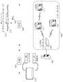
도 1은 본 발명에 따른 센서네트워크의 대규모 데이터 수집 시스템의 일 실시예를 나타내는 구성도이다.
도 2는 본 발명에 따른 센서네트워크의 대규모 데이터 수집 시스템의 데이터 흐름을 나타내는 흐름도이다.
도 3은 본 발명의 일 실시예에 따른 센서네트워크(110)의 데이터 처리 절차를 나타내는 도면이다.
도 4는 본 발명의 일 실시예에 따른 센서네트워크(110)의 대규모 데이터 수집 절차를 나타내는 도면이다.
도 5는 본 발명의 일 실시예에 따른 센서네트워크의 대규모 데이터 수집 방법을 나타내는 흐름도이다.1 is a block diagram showing an embodiment of a large-scale data collection system of the sensor network according to the present invention.
2 is a flowchart illustrating a data flow of a large data collection system of a sensor network according to the present invention.
3 is a diagram illustrating a data processing procedure of the
4 is a diagram illustrating a large-scale data collection procedure of the
5 is a flowchart illustrating a large-scale data collection method of a sensor network according to an embodiment of the present invention.
이하, 첨부된 도면들을 참조하여 본 발명의 실시예를 상세하게 설명한다. 본 명세서에서 사용되는 용어는 실시예에서의 기능 및 효과를 고려하여 선택된 용어들로서, 그 용어의 의미는 사용자 또는 운용자의 의도 또는 업계의 관례 등에 따라 달라질 수 있다. 따라서 후술하는 실시예들에서 사용된 용어의 의미는, 본 명세서에 구체적으로 명시된 경우에는 명시된 정의에 따르며, 구체적으로 명시하지 않는 경우, 당업자들이 일반적으로 인식하는 의미로 해석되어야 할 것이다.
Hereinafter, embodiments of the present invention will be described in detail with reference to the accompanying drawings. Terms used in the present specification are terms selected in consideration of functions and effects in the embodiments, and the meanings of the terms may vary according to the intention of a user or an operator or industry conventions. Therefore, the meanings of the terms used in the following embodiments are to be interpreted as meanings generally recognized by those skilled in the art when specifically stated in the present specification, and according to the specified definitions.
도 1은 본 발명에 따른 센서네트워크의 대규모 데이터 수집 시스템의 일 실시예를 나타내는 구성도이다.1 is a block diagram showing an embodiment of a large-scale data collection system of the sensor network according to the present invention.
도 1을 참조하면, 본 발명에 따른 센서네트워크의 대규모 데이터 수집 시스템은 센서네트워크(110), 센서 망 서버(130) 및 빅데이터 관리부(150)를 포함한다.Referring to FIG. 1, a large-scale data collection system of a sensor network according to the present invention includes a
종래의 하둡 기반의 데이터 수집 방식에서는 다수의 에이전트(Agent)가 네트워크 상의 여러 장소에 위치하여 로그 데이터를 수집하여 수집장치(Collector)로 전달된다. 본 발명에서는 이러한 하둡 기반의 데이터 수집 방식이 센서네트워크에서 적응적으로 수행될 수 있도록 센서네트워크(110)에 존재하는 다수의 센서 노드(111)를 에이전트로 지정하여, 센서 노드(111)에서 목적지 수집부(151)로 직접적으로 전달할 수 있도록 설정한다. 에이전트는 수집장치를 인식할 수 있어야 하므로, 하둡 기반의 에이전트 프로그램을 센서 노드(111)의 특성에 맞게 최소한의 수집부(151)에 대한 정보를 이용하여 센서 노드(111)가 수집 장치에 직접 접근하는 방법을 이용한다. 이를 통해, 설정된 데이터는 중계 서버(130)를 거쳐 목적지인 수집부(151)에 전달되고, 수집부(151)는 하둡 기반의 분산 처리부(153)에 분산되어 저장 및 처리된다.In a conventional Hadoop-based data collection method, a plurality of agents are located at various places on a network to collect log data and deliver the log data to a collector. In the present invention, a plurality of
센서네트워크(110)는 둘 이상의 센서 노드(111)로 구성된 네트워크이다. 센서네트워크(110)를 구성하는 센서 노드(111)는 하둡에서 수집할 로그데이터가 생성되는 장치에 설치되는 에이전트의 역할을 수행한다. 센서 노드(111)는 데이터 수집을 필요로 하는 여러 위치에 설치되어 감지된 데이터를 통해 센서 데이터를 생성한다. 센서 노드(111)에서 수집하는 데이터의 종류 및 형태는 센서 노드의 센서에 따라 달라질 수 있다. 예를 들어, 수질평가를 위해 설치된 센서네트워크에서 있어서, 센서네트워크의 센서 노드는 센서 노드가 설치된 위치의 수질 상태를 측정하여, 수질 상태를 나타내는 로그 데이터를 생성한다.The
센서네트워크(110)는 일반적으로 사물지능통신(Machine to Machine) 및 사물인터넷(Internet of Things) 서비스를 위해 IP(Internet Protocol)을 기반으로 할 수 있다. 이러한 IP기반의 센서네트워크(110)는 하둡 기반의 빅데이터를 수집하는 하둡에 쉽게 적응적으로 구현이 용이하다. IP기반의 센서네트워크(110)에 구비된 각각의 센서 노드(111)는 센서 데이터의 패킷을 구성할 때, 포트 번호나 목적지 주소를 포함할 수 있다. 센서 데이터의 패킷을 구성하는 포트 번호 및 목적지 주소를 이용하여 센서 데이터는 빅데이터 관리부(150)의 수집부(151)와 연계될 수 있다. 따라서 기존의 하둡기반의 에이전트를 위한 프로그램을 별도로 구축하지 않아도 센서 노드(111) 자체의 패킷 구성 방법에 의해 용이하게 수집 장치(Collector)인 수집부(151)에 전송할 수 있어 결과적으로 빅데이터 정보 수집을 실시간으로 수행할 수 있다.The
둘 이상의 센서 노드(111)는 일반적으로 게이트웨이(112)(Gateway)와 유선망 또는 무선망을 통해 연결되어 있으며, 둘 이상의 센서 노드(111)에서 수집된 센서 데이터는 유무선 네트워크망을 이용하여 게이트웨이(112)를 통해 센서 망 서버(130)로 전달된다.Two or
특히, 센서네트워크(110) 내에서는 IPv6(Internet Protocol version 6)의 주소를 통하여 메시지를 주고 받으며, 센서 망 서버(130) 이후의 인프라 망에서는 IPv4(Internet Protocol version 4)의 주소를 통하여 센서 데이터 및 메시지를 송수신할 수 있다. 센서네트워크(110)의 센서 노드(111)는 간이 망 관리 프로포콜(Simple Network Management Protocol, SNMP) 및 데이터 전송 프로토콜을 통하여 트랩(Trap) 메시지, 센서네트워크 설정 메시지(ReqSet/ReqGet Message) 및 센서 데이터 요청 결과를 포함하는 3가지 타입의 메시지를 전달할 수 있다.In particular, the
센서네트워크(110)의 센서 노드(111)에서 생성되는 센서 데이터는 게이트웨이(112)를 통해 센서 망 서버(130)를 목적지로하여 전달될 수 있다. 하지만 센서 노드(111)에서 생성된 센서 데이터의 포트 번호나 목적지 주소를 수집부(151)의 포트 번호나 목적지 주소로 설정하면, 센서 노드(111)에서 생성된 센서 데이터는 수집부(151)로 바로 전달될 수 있다. 센서 노드(111)에서 발생되는 망 관리 데이터를 위한 간이 망 관리 프로토콜(SNMP) 메시지인 트랩 메시지는 센서 망 서버(130)를 목적지로 전달되지만, 트랩 메시지의 포트 번호나 목적지 주소를 수집부(151)의 포트 번호나 목적지 주소로 설정함으로써, 트랩 메시지를 수집부(151)로 바로 전달할 수 있다.The sensor data generated at the
센서 망 서버(130)는 센서네트워크(110)로부터 수신된 센서 데이터를 수집/분석하여 데이터베이스에 저장한다. 센서 망 서버(130)에 저장된 센서 데이터는 응용 서비스 수행 시 이용할 수 있다. 센서 노드(111)에서 생성된 센서 데이터의 목적지 또는 포트 번호가 센서 망 서버(130)로 설정된 경우, 수신된 센서 데이터는 센서 망 서버(130)에 저장된다.The
빅데이터 관리부(150)는 수집부(151) 및 분산 처리부(153)를 포함한다. 빅데이터 관리부(150)는 클라우드 서버(Clous Server) 또는 엔터프라이즈 서버(Enterprise Server) 등에 위치하며, 센서네트워크(110)로부터 수신된 센서 데이터를 수집 및 정리하고, 분산하여 저장한다.The
수집부(151)는 센서네트워크(110)의 센서 노드(111)로부터 전달된 센서 데이터를 수신한다. 센서 노드(111)에서 생성된 센서 데이터의 포트 번호 또는 목적지 주소는 수집부(151)의 포트 번호 또는 목적지 주소로 설정될 수 있다. 이러한 경우, 센서 노드(111)에서 생성된 센서 데이터는 수집부(151)로 바로 전달된다. 수집부(151)는 수신된 센서 데이터를 취합하고, 취합된 센서 데이터를 분산 처리부(153)로 전달한다. 수집부(151)와 센서네트워크(110)는 데이터 송수신 관계(Data Source and Sink) 모델을 차용한다. 센서네트워크(110)의 센서 노드(111)는 소스(Source)로서, 센서 노드(111)에서 생성된 센서 데이터는 싱크(Sink) 역활을 하는 수집부(151)로 단방향으로만 전달될 수 있다.The
분산 처리부(153)는 하둡 분산 파일 시스템(Hadoop Distributed File System, HDFS)부(1531) 및 맵리듀스(MapReduce) 처리부(1532)를 포함한다.The distributed
HDFS부(1531)는 수신된 데이터를 분산해서 저장하는 하둡 분산 파일 시스템(HDFS)으로, 수집부(151)로부터 수신된 센서 데이터를 분산하여 저장한다. HDFS는 대용량 파일 저장과 처리를 위한 솔루션으로, HDFS는 하나의 서버에서만 동작 하는 게 아니라 여러 개의 서버에 설치되어서 서비스 될 수 있다. HDFS부(1531)는 센서 데이터의 메타(Meta) 정보를 관리하고 실제 센서 데이터는 여러 대의 데이터 노드(Data Node)에 분산해서 저장한다.The
센서네트워크(110)의 센서 노드(111)로부터 생성되어 전달되는 센서 데이터는 대용량을 가지는 대규모의 데이터, 즉 빅데이터이다. 따라서 센서 노드(111)로부터 전달된 센서 데이터를 분산하여 처리 및 저장하기 위하여 하둡 분산 파일 시스템을 이용하여 HDFS부(1531)에 분산하여 저장한다.The sensor data generated and transmitted from the
맵리듀스 처리부(1532)는 맵리듀스(MapReduce)를 이용하여 HDFS부(1531)를 처리 및 관리한다. 맵리듀스는 대용량의 빅데이터를 빠르고 안전하게 처리 및 분석하기 위한 분산 프로그래밍 모델이다. 맵리듀스는 빅데이터에 대한 로그 분석, 색인 구축 및 검색에서 뛰어난 능력을 보여준다. HDFS부(1531)로 전달된 센서 데이터는 대규모의 데이터이면서, 정형화/비정형화 상태의 데이터가 흩어져 있게된다. 따라서 맵리듀스 처리부(1532)는 맵리듀스를 이용하여 HDFS부(1531)에 저장된 대용량의 센서 데이터를 각각의 종류별로 정이라고 필터링(Filtering)과 소팅(Sorting)을 거쳐, 센서 데이터를 분산처리한다.The map
도 2는 본 발명에 따른 센서네트워크의 대규모 데이터 수집 시스템의 데이터 흐름을 나타내는 흐름도이다.2 is a flowchart illustrating a data flow of a large data collection system of a sensor network according to the present invention.
도 2를 참조하면, 본 발명에 따른 센서네트워크의 대규모 데이터 수집 시스템의 데이터 흐름은 크게 에이전트 계층(Agent Tier)(10), 콜렉터 계층(Collector Tier)(20) 및 저장 계층(Storage Tier)(30)을 포함하는 3가지 계층(Tier)으로 구분될 수 있다.Referring to FIG. 2, the data flow of a large data collection system of a sensor network according to the present invention is largely divided into an
에이전트 계층(10)은 로그 파일을 읽고, 데이터를 추출하고 데이터 스트림을 생산하여 콜렉터 계층으로 데이터를 전송하는 계층으로, 데이터 수집을 필요로 하는 머신에 위치한다. 본 발명에서는 센서네트워크(110) 및 센서 망 서버(130)가 에이전트 계층(10)에 해당한다. 먼저, 센서네트워크(110)는 구비된 둘 이상의 센서 노드를 통해 센서 데이터를 생성한다(201). 센서네트워크(110)가 수질평가를 위한 센서네트워크일 경우, 센서 노드에서 수집되는 센서 데이터는 해당 수질의 상태를 측정한 데이터가 될 수 있다. 그리고 센서네트워크(110)는 생성된 센서 데이터를 수집부(151)로 전달한다(202). 센서네트워크(110)는 센서 데이터 패킷의 포트 번호 또는 목적지 주소를 수집부(151)의 포트 번호 또는 목적지 주소로 설정함으로써, 센서 데이터를 수집부(151)로 바로 전달할 수 있다. 이를 통해 센서네트워크(110)는 에이전트 계층(10)의 에이전트 역할을 수행할 수 있다.The
콜렉터 계층(20)은 에이전트 계층(10)에서 생성된 빅데이터를 취합한 후, 이를 저장 계층(30)에 저장하는 계층이다. 본 발명에서는 수집부(151)가 콜렉터 계층(20)에 해당한다. 센서네트워크(110)로부터 대용량의 센서 데이터를 수신한 수집부(151)는 수신된 센서 데이터를 저장 계층(30)의 HDFS부(1531)로 전달한다(203). 수집부(151)는 센서네트워크(110)로부터 전달된 센서 데이터를 수신한다. 센서네트워크(110)에서 생성된 센서 데이터의 포트 번호 또는 목적지 주소는 수집부(151)의 포트 번호 또는 목적지 주소로 설정될 수 있다. 이러한 경우, 센서네트워크(110)에서 생성된 센서 데이터는 수집부(151)로 바로 전달된다. 수집부(151)는 수신된 센서 데이터를 취합하고, 취합된 센서 데이터를 분산 처리부(153)로 전달한다. 수집부(151)와 센서네트워크(110)는 데이터 송수신 관계(Data Source and Sink) 모델을 차용한다. 센서네트워크(110)는 소스로서, 센서네트워크(110)에서 생성된 센서 데이터는 싱크 역활을 하는 수집부(151)로 단방향으로만 전달될 수 있다.The
저장 계층(30)은 빅데이터를 분산 저장하여 처리하는 기능을 수행한다. 본 발명에서는 HDFS부(1531) 및 맵리듀스 처리부(1532)가 저장 계층(30)에 해당한다. 콜렉터 계층(20)인 수집부(151)로부터 센서 데이터를 수신한 HDFS부(1531)는 수신된 센서 데이터를 분산하여 저장한다(204). 센서네트워크(110)로부터 생성되어 전달되는 센서 데이터는 대용량을 가지는 대규모의 데이터, 즉 빅데이터이다. 따라서 수신된 센서 데이터를 분산하여 처리 및 저장하기 위하여 하둡 분산 파일 시스템을 이용하여 HDFS부(1531)에 분산하여 저장한다.The
다음으로 맵리듀스 처리부(1532)는 맵리듀스를 이용하여 HDFS부(1531)를 처리 및 관리한다(205). 맵리듀스는 대용량의 빅데이터를 빠르고 안전하게 처리 및 분석하기 위한 분산 프로그래밍 모델이다. 맵리듀스는 빅데이터에 대한 로그 분석, 색인 구축 및 검색에서 뛰어난 능력을 보여준다. HDFS부(1531)로 전달된 센서 데이터는 대규모의 데이터이면서, 정형화/비정형화 상태의 데이터가 흩어져 있게된다. 따라서 맵리듀스 처리부(1532)는 맵리듀스를 이용하여 HDFS부(1531)에 저장된 대용량의 센서 데이터를 각각의 종류별로 정이라고 필터링(Filtering)과 소팅(Sorting)을 거쳐, 센서 데이터를 분산처리한다.Next, the map
도 3은 본 발명의 일 실시예에 따른 센서네트워크(110)의 데이터 처리 절차를 나타내는 도면이다.3 is a diagram illustrating a data processing procedure of the
도 3을 참조하면, 본 발명의 일 실시예에 따른 센서네트워크(110)는 센서 네트워크(110) 내에서는 IPv6(Internet Protocol 6)의 주소(310)를 통하여 센서 데이터를 송수신하며, 센서 망 서버(130) 이후의 인프라 망에서는 IPv4(Internet Protocol 4)의 주소(320)를 통하여 센서 데이터를 송수신한다. 센서네트워크(110)의 센서 노드(111)는 간이 망 관리 프로프콜(Simple Network Management Protocol, SNMP) 및 데이터 전송 프로토콜을 통하여 3가지 유형의 센서 메시지를 이용하여 센서 망 서버(130)와 정보를 교환한다. 3가지 유형의 센서 메시지는 트랩(Trap) 메시지(311), 센서네트워크 설정 메시지(ReqSet/ReqGet Message)(312) 및 센서 데이터 요청 결과(313)를 포함한다. 트랩 메시지(311)는 센서네트워크(110)에서 발생된 망 관리 정보를 센서 망 서버(130)에 전달한다. 센서네트워크 설정 메시지(312)는 센서 망 서버(130)로부터 센서네트워크(110) 관리 정보를 설정하거나 가져오도록 하는 메시지이다. 센서 데이터 요청 결과(313)는 센서네트워크(110)에서 발생된 센서 데이터를 미리 설정된 주기에 의해 주기적으로 센서 망 서버(130)에 전달하는 메시지이다. 센서네트워크(110)의 센서 노드(111)에서 생성된 센서 데이터가 무선망을 통해 게이트웨이(112)를 통해 센서 망 서버(130)에 수집되게 된다. 센서 망 서버(130)는 센서 데이터를 수집 분석하여 데이터베이스(131)에 저장하여 응용 서비스 수행 시 이를 이용한다.Referring to FIG. 3, the
표 1은 수질평가를 위한 센서네트워크를 통해 수집될 수 있는 데이터 종류의 실시예를 나타낸다. 센서네트워크를 통해 수집될 수 있는 데이터 종류는 크게 센서 데이터 및 제어 데이터를 포함한다. 데이터 수집대상은 정기적으로 수집되는 센서 데이터, 정기적인 네트워크 요소 장애 감시(Supervision) 및 장애 탐지 보고(Trap), 현재 센서네트워크(110)의 상태 정보 및 운용자 제어 데이터를 포함할 수 있다. 상술한 도 1, 도 2 및 도 3에 기재된 센서 데이터는 표 1에 포함된 다양한 데이터 종류를 모두 포함할 수 있다.Table 1 shows an example of the types of data that can be collected through the sensor network for water quality assessment. Types of data that can be collected through the sensor network largely include sensor data and control data. The data collection target may include regularly collected sensor data, regular network element failure monitoring (Supervision) and failure detection report (Trap), status information of the
전기전도도
용존산소
수소이온농도
산화환원준위
탁도
엽록소
NO3-N
NH4-N
수심
순시유량
유속#1
유속#2Water temperature
Electrical conductivity
Dissolved oxygen
Hydrogen ion concentration
Redox level
Turbidity
chlorophyll
NO3 -N
NH4 -N
depth of water
Instantaneous flow rate
세정장치 장애
배터리 저전압
센서노드 수몰 장애
수심센서 장애
유속A 장애
유속B 장애
Restart 보고
RF모듈장애
센서 장애
장치 장애
전원 장애
pH probe 장애Water Sensor Failure
Scrubber failure
Battery low voltage
Sensor node flood failure
Depth sensor failure
Flow A Disorder
Flow B Disorder
Restart report
RF module failure
Sensor failure
Device failure
Power failure
pH probe failure
센서 상태
현재수위
순시유량
온도
세정장치 동작주기 정보
센서데이터 측정주기정보
경계수위
침수수위
현재유속A
현재유속B
Do probe 상태
Tur probe 상태
Chl probe 상태
WT probe 상태
pH probe 상태
EC probe 상태
ORP probe 상태Battery level
Sensor status
Current water level
Instantaneous flow rate
Temperature
Cleaning device operation cycle information
Sensor data measurement cycle information
Boundary water level
Flood level
Current flow rate A
Current flow rate B
Do probe status
Tur probe status
Chl probe status
WT probe status
pH probe status
EC probe status
ORP probe status
센서저장메모리 초기화
세정장치 동작 제어
센서 enable
센서 disable
USN 센서모듈 reset
세정장치 동작 주기 변경
센서데이터 측정주기변경
경계수위 설정
침수수위 설정
USN통신모듈 Reset
유속A센서 Reset
유속B센서 Reset
수심센서 ResetSensor reset
Initialize sensor storage memory
Cleaning device operation control
Sensor enable
Sensor disable
USN sensor module reset
Change of cleaning device operation cycle
Change of sensor data measurement cycle
Boundary water level setting
Immersion level setting
USN Communication Module Reset
Flow A Sensor Reset
Flow B Sensor Reset
Depth Sensor Reset
도 4는 본 발명의 일 실시예에 따른 센서네트워크(110)의 대규모 데이터 수집 절차를 나타내는 도면이다.4 is a diagram illustrating a large-scale data collection procedure of the
도 4를 참조하면, 센서네트워크(110)는 IP기반 센서네트워크로서, 하둡 기반의 빅데이터를 수집하는 하둡에 쉽게 적응적으로 구현될 수 있다.Referring to FIG. 4, the
수집부(151)의 포트 번호 또는 목적지 번호(401)를 35853으로 가정한다. 센서 노드(111)에서 생성되는 센서 데이터는 센서 데이터 프로토콜에 의해 게이트웨이(112)를 통하여 센서 망 서버(130)를 목적지로 전달된다. 하지만, 센서 데이터의 포트 번호나 목적지 주소(403)를 수집부(151)의 포트 번호나 목적지 번호(401)로 설정함으로써, 빅데이터 서비스를 위한 데이터 수집을 수집부(151)를 통해 HDFSD부(1531)로 직접 전달한다. 또한 센서 노드(111)에서 발생되는 망 관리 데이터를 위한 간이 망 관리 프로토콜(SNMP) 메시지는 센서 망 서버(130)를 목적지로 전달되지만 포트 번호나 목적지 주소(402)를 수집부(151)의 포트 번호나 목적지 주소(401)로 설정하여 빅데이터 서비스를 위한 데이터 수집을 수집부(151)를 통해 HDFS부(1531)로 직접 전달한다. 마스터(Master)(401)는 하둡 기반 에이전트 노드에서 콜렉터 노드로 데이터를 전송할 때 데이터 흐름의 동적 설정을 가능하게 해주는 기능이다. 마스터를 통해 센서네트워크(110)에서 센서 노드(111)는 에이전트의 싱크를 생략할 수 있으며, 콜렉터의 소스를 실제 콜렉터인 수집부(151)의 소스 포트로 지정하면 된다. 즉, 센서네트워크(110)의 센서 노드(111)와 수집부(151) 사이의 관계는 싱크와 소스 관계로서, 각각의 센서 노드(111)는 싱크 설정이 필요없이 소스 설정을 수집부(151)의 포트 번호로 지정함으로써, 다수의 센서 노드(111)의 데이터가 수집부(151)로 전달된다.Assume that the port number or the
도 5는 본 발명의 일 실시예에 따른 센서네트워크의 대규모 데이터 수집 방법을 나타내는 흐름도이다.5 is a flowchart illustrating a large-scale data collection method of a sensor network according to an embodiment of the present invention.
도 5를 참조하면, 본 발명의 일 실시예에 따른 센서네트워크의 대규모 데이터 수집 방법은 먼저, 센서네트워크의 센서 노드에서 수집된 데이터에 기초하여 센서 데이터를 생성한다(501). 센서네트워크는 둘 이상의 센서 노드로 구성된 네트워크이다. 센서 노드는 하둡에서 수집할 로그데이터가 생성되는 장치에 설치되는 에이전트의 역할을 수행한다. 센서 노드는 데이터 수집을 필요로 하는 여러 위치에 설치되어 감지된 데이터를 통해 센서 데이터를 생성한다. 센서네트워크는 일반적으로 사물지능통신(Machine to Machine) 및 사물인터넷(Internet of Things) 서비스를 위해 IP(Internet Protocol)을 기반으로 할 수 있다. 이러한 IP기반의 센서네트워크(110)는 하둡 기반의 빅데이터를 수집하는 하둡에 쉽게 적응적으로 구현이 용이하다.Referring to FIG. 5, in the large-scale data collection method of a sensor network according to an embodiment of the present invention, first, sensor data is generated based on data collected at a sensor node of the sensor network (501). The sensor network is a network composed of two or more sensor nodes. The sensor node acts as an agent installed in the device where the log data to be collected in Hadoop is generated. Sensor nodes are installed at various locations that require data collection and generate sensor data from the sensed data. Sensor networks can generally be based on IP (Internet Protocol) for Machine to Machine and Internet of Things services. The IP-based
특히, 센서네트워크 내에서는 IPv6(Internet Protocol version 6)의 주소를 통하여 메시지를 주고 받으며, 센서 망 서버 이후의 인프라 망에서는 IPv4(Internet Protocol version 4)의 주소를 통하여 센서 데이터 및 메시지를 송수신할 수 있다. 센서네트워크의 센서 노드는 간이 망 관리 프로포콜(SNMP) 및 데이터 전송 프로토콜을 통하여 트랩(Trap) 메시지, 센서네트워크 설정 메시지(ReqSet/ReqGet Message) 및 센서 데이터 요청 결과를 포함하는 3가지 타입의 메시지를 전달할 수 있다. 트랩 메시지는 센서네트워크에서 발생된 망 관리 정보를 센서 망 서버에 전달한다. 센서네트워크 설정 메시지는 센서 망 서버로부터 센서네트워크 관리 정보를 설정하거나 가져오도록 하는 메시지이다. 센서 데이터 요청 결과는 센서네트워크에서 발생된 센서 데이터를 미리 설정된 주기에 의해 주기적으로 센서 망 서버(130)에 전달하는 메시지이다. 센서네트워크에서 생성되는 데이터는 기본적으로 센서 데이터를 포함하며, 센서네트워크에 대한 제어 데이터를 더 포함할 수 있다. 데이터 수집대상은 정기적으로 수집되는 센서 데이터, 정기적인 네트워크 요소 장애 감시(Supervision) 및 장애 탐지 보고(Trap), 현재 센서네트워크(110)의 상태 정보 및 운용자 제어 데이터를 포함할 수 있다.In particular, in the sensor network, messages can be exchanged through an IPv6 (Internet Protocol version 6) address, and in the infrastructure network after the sensor network server, sensor data and messages can be transmitted and received through an IPv4 (Internet Protocol version 4) address. . Sensor nodes of the sensor network use three types of messages, including trap messages, sensor network setup messages (ReqSet / ReqGet Message), and sensor data request results, through simple network management protocol (SNMP) and data transfer protocols. I can deliver it. The trap message transmits network management information generated in the sensor network to the sensor network server. The sensor network setting message is a message for setting or getting sensor network management information from the sensor network server. The sensor data request result is a message that periodically transmits the sensor data generated in the sensor network to the
다음으로 센서 데이터의 포트 번호를 설정한다(502). 센서네트워크에서 생성되는 센서 데이터는 센서 데이터의 포트 번호나 목적지 주소를 수집부의 포트 번호나 목적지 번호로 설정함으로써, 빅데이터 서비스를 위한 데이터 수집을 수집부를 통해 HDFSD부로 직접 전달한다. 또한 센서네트워크에서 발생되는 망 관리 데이터를 위한 간이 망 관리 프로토콜(SNMP) 메시지는 또한 포트 번호나 목적지 주소를 수집부의 포트 번호나 목적지 주소로 설정하여 빅데이터 서비스를 위한 데이터 수집을 수집부를 통해 HDFS부로 직접 전달한다.Next, a port number of sensor data is set (502). The sensor data generated in the sensor network sets the port number or the destination address of the sensor data as the port number or the destination number of the collection unit, thereby directly transferring data collection for the big data service to the HDFSD unit through the collection unit. In addition, the Simple Network Management Protocol (SNMP) message for network management data generated in the sensor network also sets the port number or destination address as the port number or destination address of the collector to collect data for the big data service through the collector to the HDFS unit. Pass it directly.
그리고 빅데이터 관리부는 센서 데이터를 수집한다(503). 포트 번호가 설정된 센서 데이터를 빅데이터 관리부로 전달한다. 센서 데이터는 센서 데이터에 설정된 포트 번호에 기초하여 빅데이터 관리부의 수집부로 바로 전달된다.The big data manager collects sensor data (503). Transmit sensor data with port number to big data manager. The sensor data is transferred directly to the collection unit of the big data management unit based on the port number set in the sensor data.
다음으로 빅데이터 관리부는 수신된 센서 데이터를 분산 처리하여 저장한다(504). 빅데이터 관리부는 수신된 센서 데이터를 하둡 분산 파일 시스템(HDFS)을 통해 저장한다. HDFS는 대용량 파일 저장과 처리를 위한 솔루션으로, HDFS는 하나의 서버에서만 동작 하는 게 아니라 여러 개의 서버에 설치되어서 서비스될 수 있다. 센서네트워크로부터 생성되어 전달되는 센서 데이터는 대용량을 가지는 대규모의 데이터, 즉 빅데이터이다. 따라서 수신된 센서 데이터를 분산하여 처리 및 저장하기 위하여 하둡 분산 파일 시스템을 이용하여 분산하여 저장한다. 그리고 맵리듀스(MapReduce)를 이용하여 HDFS를 처리 및 관리한다. 맵리듀스는 대용량의 빅데이터를 빠르고 안전하게 처리 및 분석하기 위한 분산 프로그래밍 모델이다. 맵리듀스는 빅데이터에 대한 로그 분석, 색인 구축 및 검색에서 뛰어난 능력을 보여준다. 수신된 센서 데이터는 대규모의 데이터이면서, 정형화/비정형화 상태의 데이터가 흩어져 있다. 따라서 맵리듀스를 이용하여 HDFS에 저장된 대용량의 센서 데이터를 각각의 종류별로 정리하고 필터링(Filtering)과 소팅(Sorting)을 거쳐, 센서 데이터를 분산처리한다.
Next, the big data manager distributes and stores the received sensor data (504). The big data management unit stores the received sensor data through the Hadoop Distributed File System (HDFS). HDFS is a solution for storing and processing large files. HDFS can be installed and serviced on multiple servers instead of just one server. The sensor data generated and transmitted from the sensor network is large data having a large capacity, that is, big data. Therefore, in order to distribute, process and store the received sensor data, the Hadoop distributed file system is distributed and stored. It also uses MapReduce to process and manage HDFS. MapReduce is a distributed programming model for processing and analyzing large volumes of big data quickly and securely. MapReduce demonstrates its superior ability in log analysis, indexing and retrieval of big data. The received sensor data is large-scale data, and the data of the standardized / unstructured state is scattered. Therefore, MapReduce uses a large amount of sensor data stored in HDFS for each type and filters and sorts the sensor data in a distributed manner.
이상 바람직한 실시예를 들어 본 발명을 상세하게 설명하였으나, 본 발명은 전술한 실시예에 한정되지 않고, 본 발명의 기술적 사상의 범위 내에서 당분야에서 통상의 지식을 가진자에 의하여 여러 가지 변형이 가능하다.Although the present invention has been described in detail with reference to preferred embodiments, the present invention is not limited to the above-described embodiments, and various modifications may be made by those skilled in the art within the scope of the technical idea of the present invention. It is possible.
110: 센서네트워크
111: 센서 노드
112: 게이트웨이
130: 센서 망 서버
150: 빅데이터 관리부
151: 수집부
153: 분산 처리부
1531: HDFS부
1532: 맵리듀스 처리부110: sensor network
111: sensor node
112: gateway
130: sensor network server
150: big data management
151: collector
153: distributed processing unit
1531: HDFS
1532: map reduce processing unit
Claims (14)
Translated fromKorean각각의 센서 데이터를 생성하는 복수의 센서 노드들;
게이트 웨이; 및
상기 게이트 웨이를 통해 상기 센서 노드들 각각에서 생성된 센서 데이터를 수신하고, 상기 센서 데이터를 분산 저장하는 하둡(Hadoop) 시스템을 처리하는 콜렉터로 전송하는 센서 네트워크 서버를 포함하되,
상기 콜렉터는 상기 시스템의 제2티어에 포함되고, 상기 센서 네트워크로부터 수신된 상기 센서 데이터를 통합하고,
상기 제1티어에 포함된 상기 센서 노드들과 상기 센서 네트워크 서버 사이의 통신은 IP의 제1버전에 기초하여 수행되고, 상기 제1티어에 포함된 센서 네트워크 서버와 상기 제2티어에 포함된 콜렉터 사이의 통신은 상기 IP의 제1버전과 다르게 구성되는 상기 IP의 제2버전에 기초하여 수행되고,
상기 복수의 센서 노드들 각각에 의해 생성된 상기 센서 데이터의 목적지 주소는 상기 콜렉터의 IP 주소로 설정되는 것을 특징으로 하는 센서네트워크의 대규모 데이터 수집 시스템.A sensor network included in the first tier of the system, wherein the sensor network comprises:
A plurality of sensor nodes generating respective sensor data;
Gateway; And
Receiving sensor data generated in each of the sensor nodes through the gateway, and includes a sensor network server for transmitting to the collector processing a Hadoop (Hadoop) system to distribute and store the sensor data,
The collector is included in the second tier of the system, aggregates the sensor data received from the sensor network,
Communication between the sensor nodes included in the first tier and the sensor network server is performed based on a first version of IP, and the sensor network server included in the first tier and the collector included in the second tier. Communication is performed based on the second version of the IP configured differently from the first version of the IP,
And a destination address of the sensor data generated by each of the plurality of sensor nodes is set to an IP address of the collector.
상기 센서네트워크는 사물지능통신(Machine to Machine) 및 사물인터넷(Internet of Things) 서비스를 위해 IP(Internet Protocol)을 기반으로 형성될 수 있는 것을 특징으로 하는 센서네트워크의 대규모 데이터 수집 시스템.The method of claim 1,
The sensor network is a large-scale data collection system of the sensor network, characterized in that can be formed based on the Internet Protocol (IP) for the Machine to Machine (Machine to Machine) and the Internet of Things (Internet of Things) services.
상기 IP의 제1버전은 IPv6(Internet Protocol version 6)의 주소에 대응되며,
상기 IP의 제2버전은 IPv4(Internet Protocol version 4)의 주소에 대응되는 것을 특징으로 하는 센서네트워크의 대규모 데이터 수집 시스템.The method of claim 1,
The first version of the IP corresponds to an address of Internet Protocol version 6 (IPv6),
The second version of the IP is a large-scale data collection system of the sensor network, characterized in that corresponding to the address of the IPv4 (Internet Protocol version 4).
상기 센서네트워크의 센서 노드들 각각은 간이 망 관리 프로토콜(Simple Network Management Protocol, SNMP) 및 데이터 전송 프로토콜 중에서 적어도 하나를 이용하여 데이터를 전달하는 것을 특징으로 하는 센서네트워크의 대규모 데이터 수집 시스템.The method of claim 1,
Each of the sensor nodes of the sensor network transfers data using at least one of a simple network management protocol (SNMP) and a data transmission protocol.
상기 센서 노드는 트랩(Trap) 메시지, 센서네트워크 설정 메시지 및 센서 데이터 요청 결과 중에서 적어도 하나 이상을 전달하는 것을 특징으로 하는 센서네트워크의 대규모 데이터 수집 시스템.The method of claim 4, wherein
The sensor node transmits at least one or more of a trap message, a sensor network configuration message, and a sensor data request result.
상기 콜렉터는, 상기 통합된 센서 데이터를 하둡 분산 파일 시스템(Hadoop Distributed File System, HDFS)의 분산 처리부로 전달하고
상기 분산 처리부는, 상기 통합된 센서 데이터를 하둡 분산 파일 시스템(Hadoop Distributed File System, HDFS)을 이용하여 분산해서 저장하며, 맵리듀스(MapReduce)를 이용하여 상기 HDFS에 저장된 데이터를 분석 및 처리하는 것을 특징으로 하는 센서네트워크의 대규모 데이터 수집 시스템.The method of claim 1,
The collector delivers the integrated sensor data to a distributed processing unit of Hadoop Distributed File System (HDFS).
The distributed processor is configured to distribute and store the integrated sensor data using a Hadoop Distributed File System (HDFS), and to analyze and process data stored in the HDFS using MapReduce. Large-scale data acquisition system of sensor network.
상기 센서 노드들 각각은,
상기 센서네트워크 요소 장애 감시(Supervision), 상기 센서네트워크의 장애 탐지 보고 및 운용자 제어 데이터 중에서 적어도 어느 하나를 상기 콜렉터로 전달하는 것을 특징으로 하는 센서네트워크의 대규모 데이터 수집 시스템.The method of claim 1,
Each of the sensor nodes,
And transmitting at least one of the sensor network element failure monitoring (Supervision), the failure detection report of the sensor network, and the operator control data to the collector.
상기 센서 네트워크 서버가, 상기 센서 네트워크의 센서 노드들 각각에 의해 생성된 센서 데이터를 상기 센서 네트워크의 게이트웨이를 통해 수신하는 단계;
상기 센서 네트워크 서버가, 상기 센서 데이터를 상기 센서 데이터를 분산 저장하는 하둡(Hadoop) 시스템을 처리하는 콜렉터로 전송하는 단계;를 포함하며,
상기 센서 네트워크는 상기 센서 노드들, 상기 게이트웨이, 및 시스템의 제1티어에 포함된 센서네트워크 상기 센서 네트워크 서버를 포함하고, 상기 콜렉터는 상기 시스템의 제2티어에 포함되고,
상기 제1티어에 포함된 상기 센서 노드들과 상기 센서 네트워크 서버 사이의 통신은 IP의 제1버전에 기초하여 수행되고, 상기 제1티어에 포함된 센서 네트워크 서버와 상기 제2티어에 포함된 콜렉터 사이의 통신은 상기 IP의 제1버전과 다르게 구성되는 상기 IP의 제2버전에 기초하여 수행되고,
상기 복수의 센서 노드들 각각에 의해 생성된 상기 센서 데이터의 목적지 주소는 상기 콜렉터의 IP 주소로 설정되는 것을 특징으로 하는 센서네트워크의 대규모 데이터 수집 방법.In the sensor network server included in the sensor network, a method for transmitting sensor data for large-scale data integration,
Receiving, by the sensor network server, sensor data generated by each of the sensor nodes of the sensor network through a gateway of the sensor network;
And transmitting, by the sensor network server, the sensor data to a collector that processes a Hadoop system for distributing and storing the sensor data.
The sensor network includes the sensor nodes, the gateway, and the sensor network server included in the first tier of the system, the collector is included in the second tier of the system,
Communication between the sensor nodes included in the first tier and the sensor network server is performed based on a first version of IP, and the sensor network server included in the first tier and the collector included in the second tier. Communication is performed based on the second version of the IP configured differently from the first version of the IP,
And a destination address of the sensor data generated by each of the plurality of sensor nodes is set as an IP address of the collector.
상기 수집된 센서 데이터를 하둡 분산 파일 시스템(HDFS)를 통해 저장하는 단계;
상기 하둡 분산 파일 시스템에 저장된 센서 데이터를 맵리듀스(MapReduce)를 이용하여 분석하고, 필터링(Filtering)과 소팅(Sorting)을 거쳐 분산 처리하는 단계;
를 포함하는 것을 특징으로 하는 센서네트워크의 대규모 데이터 수집 방법.The method of claim 8,
Storing the collected sensor data through Hadoop Distributed File System (HDFS);
Analyzing sensor data stored in the Hadoop distributed file system using MapReduce and performing distributed processing through filtering and sorting;
Large-scale data collection method of the sensor network comprising a.
상기 센서네트워크는 IP(Internet Protocol)을 기반으로 형성될 수 있는 것을 특징으로 하는 센서네트워크의 대규모 데이터 수집 방법.The method of claim 8,
The sensor network may be formed based on IP (Internet Protocol).
상기 IP의 제1버전은 IPv6(Internet Protocol version 6)의 주소에 대응되며,
상기 IP의 제2버전은 IPv4(Internet Protocol version 4)의 주소에 대응되는 것을 특징으로 하는 센서네트워크의 대규모 데이터 수집 방법.The method of claim 8,
The first version of the IP corresponds to an address of Internet Protocol version 6 (IPv6),
And a second version of the IP corresponds to an address of IPv4 (Internet Protocol version 4).
상기 센서 노드들 각각은 간이 망 관리 프로토콜(Simple Network Management Protocol, SNMP) 및 데이터 전송 프로토콜 중에서 적어도 하나를 이용하여 데이터를 전달하는 것을 특징으로 하는 센서네트워크의 대규모 데이터 수집 방법.The method of claim 8,
Each of the sensor nodes transmits data using at least one of a simple network management protocol (SNMP) and a data transmission protocol.
상기 센서 노드들 각각은 트랩(Trap) 메시지, 센서네트워크 설정 메시지 및 센서 데이터 요청 결과 중에서 적어도 하나 이상을 전달하는 것을 특징으로 하는 센서네트워크의 대규모 데이터 수집 방법.The method of claim 12,
And each of the sensor nodes delivers at least one of a trap message, a sensor network configuration message, and a sensor data request result.
상기 센서 노드들 각각은, 상기 센서네트워크 요소 장애 감시(Supervision), 상기 센서네트워크의 장애 탐지 보고 및 운용자 제어 데이터 중에서 적어도 어느 하나를 포함하여 상기 콜렉터로 전달하는 것을 특징으로 하는 센서네트워크의 대규모 데이터 수집 방법.The method of claim 8,
Each of the sensor nodes includes at least one of the sensor network element failure monitoring (Supervision), the failure detection report of the sensor network, and the operator control data, and transmits the data to the collector. Way.
Priority Applications (2)
| Application Number | Priority Date | Filing Date | Title |
|---|---|---|---|
| KR1020130035400AKR102029285B1 (en) | 2013-04-01 | 2013-04-01 | System and method for big data aggregaton in sensor network |
| US14/162,843US9917735B2 (en) | 2013-04-01 | 2014-01-24 | System and method for big data aggregation in sensor network |
Applications Claiming Priority (1)
| Application Number | Priority Date | Filing Date | Title |
|---|---|---|---|
| KR1020130035400AKR102029285B1 (en) | 2013-04-01 | 2013-04-01 | System and method for big data aggregaton in sensor network |
Publications (2)
| Publication Number | Publication Date |
|---|---|
| KR20140119561A KR20140119561A (en) | 2014-10-10 |
| KR102029285B1true KR102029285B1 (en) | 2019-10-07 |
Family
ID=51621953
Family Applications (1)
| Application Number | Title | Priority Date | Filing Date |
|---|---|---|---|
| KR1020130035400AExpired - Fee RelatedKR102029285B1 (en) | 2013-04-01 | 2013-04-01 | System and method for big data aggregaton in sensor network |
Country Status (2)
| Country | Link |
|---|---|
| US (1) | US9917735B2 (en) |
| KR (1) | KR102029285B1 (en) |
Families Citing this family (31)
| Publication number | Priority date | Publication date | Assignee | Title |
|---|---|---|---|---|
| US20160050128A1 (en)* | 2014-08-12 | 2016-02-18 | Raco Wireless LLC | System and Method for Facilitating Communication with Network-Enabled Devices |
| US11051140B2 (en)* | 2014-09-19 | 2021-06-29 | Texas Instruments Incorporated | Compression of internet protocol version 6 addresses in wireless sensor networks |
| KR102131650B1 (en) | 2014-12-23 | 2020-07-09 | 한국전자통신연구원 | Apparatus and method for data processing |
| US10078671B2 (en) | 2015-02-26 | 2018-09-18 | Red Hat, Inc. | Data hub architecture to provide actionable data from remote sensor feeds |
| CN104748796A (en)* | 2015-03-30 | 2015-07-01 | 浪潮集团有限公司 | Sensing method, sensor and sensor cluster |
| CN104898608A (en)* | 2015-04-10 | 2015-09-09 | 南京理工大学 | Hadoop-based crop growth monitoring cloud platform and realization method thereof |
| JP6241449B2 (en)* | 2015-05-21 | 2017-12-06 | 横河電機株式会社 | Data management system and data management method |
| KR20160140185A (en)* | 2015-05-29 | 2016-12-07 | 삼성전자주식회사 | Device and method for performing communication service |
| US10536357B2 (en)* | 2015-06-05 | 2020-01-14 | Cisco Technology, Inc. | Late data detection in data center |
| US10091110B2 (en)* | 2015-10-28 | 2018-10-02 | Electronics And Telecommunications Research Institute | Edge-based load shedding system for fast data analysis and operating method thereof |
| CN105243285A (en)* | 2015-11-10 | 2016-01-13 | 广州西麦科技股份有限公司 | Big data health forecast system |
| CN105447146A (en)* | 2015-11-26 | 2016-03-30 | 陕西艾特信息化工程咨询有限责任公司 | Massive data collecting and exchanging system and method |
| GB2546120B (en) | 2016-02-09 | 2018-02-14 | Spatialbuzz Ltd | Fault monitoring in a utility supply network |
| GB2546118B (en) | 2016-02-09 | 2018-11-14 | Spatialbuzz Ltd | Fault monitoring by assessing spatial distribution of queries in a utility supply network |
| KR102592611B1 (en) | 2016-02-18 | 2023-10-23 | 한국전자통신연구원 | Map reduce apparatus, controller for map reduce and method thereof |
| US10382358B1 (en) | 2016-06-13 | 2019-08-13 | Amazon Technologies. Inc. | Multi-tiered data processing service |
| US10516589B2 (en) | 2016-08-31 | 2019-12-24 | At&T Intellectual Property I, L.P. | Sensor web management system for internet of things sensor devices with physically imprinted unique frequency keys |
| CN107070590B (en)* | 2016-12-30 | 2020-12-29 | 南京海道普数据技术有限公司 | WSN perception data distributed decoding method based on MapReduce |
| CN107528728A (en)* | 2017-08-23 | 2017-12-29 | 绵阳美菱软件技术有限公司 | A kind of method and device for obtaining user experience data |
| US10355824B2 (en) | 2017-10-23 | 2019-07-16 | Bank Of America Corporation | Smart integrated cyclic data transport |
| KR102507837B1 (en)* | 2017-11-14 | 2023-03-07 | 주식회사 케이티 | Method and Apparatus for Quality Management of Data |
| CN108881298A (en)* | 2018-07-30 | 2018-11-23 | 淮安信息职业技术学院 | A kind of network safety system and implementation method based on big data platform |
| CN111125208A (en)* | 2018-10-30 | 2020-05-08 | 华为技术有限公司 | A data acquisition and processing method, device and system |
| KR102166415B1 (en)* | 2019-02-22 | 2020-10-16 | 트라이콤텍 주식회사 | Seismic prediction system using IoT gateway and Seismic prediction method using the same |
| US11502905B1 (en) | 2019-12-19 | 2022-11-15 | Wells Fargo Bank, N.A. | Computing infrastructure standards assay |
| US11237847B1 (en) | 2019-12-19 | 2022-02-01 | Wells Fargo Bank, N.A. | Automated standards-based computing system reconfiguration |
| US11556820B2 (en) | 2020-01-03 | 2023-01-17 | Blackberry Limited | Method and system for a dynamic data collection and context-driven actions |
| KR102262463B1 (en) | 2020-03-11 | 2021-06-08 | 동의대학교 산학협력단 | System and Method for Collecting Sensor Data in Large Scale Sensors Networks for Sensor Mat |
| KR102327788B1 (en)* | 2020-04-14 | 2021-11-17 | 대진대학교 산학협력단 | Disaster prediction system using IoT device and disaster prediction method using the same |
| CN114491484A (en)* | 2022-01-17 | 2022-05-13 | 北京国信网联科技有限公司 | Big data-based information security defense system |
| CN119850191B (en)* | 2025-03-19 | 2025-06-20 | 温州市渔业技术推广站(温州市水生动物防疫检疫中心温州市渔业环境监测站) | A method and device for synchronously collecting multi-dimensional data of marine environment |
Citations (4)
| Publication number | Priority date | Publication date | Assignee | Title |
|---|---|---|---|---|
| US20040264406A1 (en)* | 2003-06-30 | 2004-12-30 | Pattenden Christopher E.S. | Methods and apparatus for processing radio modem commands during network data sessions |
| US20060202834A1 (en)* | 2005-03-03 | 2006-09-14 | Norihiko Moriwaki | Sensor network system and data retrieval method for sensing data |
| JP4920052B2 (en)* | 2009-03-11 | 2012-04-18 | 株式会社日立製作所 | Communication system and server |
| US20120182891A1 (en)* | 2011-01-19 | 2012-07-19 | Youngseok Lee | Packet analysis system and method using hadoop based parallel computation |
Family Cites Families (11)
| Publication number | Priority date | Publication date | Assignee | Title |
|---|---|---|---|---|
| CA2145921A1 (en)* | 1994-05-10 | 1995-11-11 | Vijay Pochampalli Kumar | Method and apparatus for executing a distributed algorithm or service on a simple network management protocol based computer network |
| WO2007027958A1 (en)* | 2005-08-29 | 2007-03-08 | Junaid Islam | ARCHITECTURE FOR MOBILE IPv6 APPLICATIONS OVER IPv4 |
| US8279870B2 (en)* | 2007-08-01 | 2012-10-02 | Silver Spring Networks, Inc. | Method and system of routing in a utility smart-grid network |
| US8683077B2 (en)* | 2008-06-24 | 2014-03-25 | Blackberry Limited | Method for indicating supported IP versions and reaching a device that supports compatible IP versions with SIP |
| US20110158160A1 (en)* | 2009-12-31 | 2011-06-30 | Elster Electricity, Llc | Ip encapsulation and routing over wireless radio networks |
| US8844041B1 (en)* | 2010-01-12 | 2014-09-23 | Symantec Corporation | Detecting network devices and mapping topology using network introspection by collaborating endpoints |
| US9148373B2 (en)* | 2010-07-30 | 2015-09-29 | Intellectual Discovery Co., Ltd. | Network system |
| JP5194074B2 (en)* | 2010-08-20 | 2013-05-08 | 株式会社日立製作所 | Communication device |
| KR20120085400A (en) | 2011-01-24 | 2012-08-01 | 충남대학교산학협력단 | Packet Processing System and Method by Prarllel Computation Based on Hadoop |
| US9225639B2 (en)* | 2011-01-31 | 2015-12-29 | Intellectual Discovery Co., Ltd. | Network system |
| KR101591289B1 (en)* | 2011-03-30 | 2016-02-04 | 주식회사 케이티 | A Methods and Apparatus of separated software upgrade of Device and Gateway by over the air in the Machine to machine communication |
- 2013
- 2013-04-01KRKR1020130035400Apatent/KR102029285B1/ennot_activeExpired - Fee Related
- 2014
- 2014-01-24USUS14/162,843patent/US9917735B2/ennot_activeExpired - Fee Related
Patent Citations (4)
| Publication number | Priority date | Publication date | Assignee | Title |
|---|---|---|---|---|
| US20040264406A1 (en)* | 2003-06-30 | 2004-12-30 | Pattenden Christopher E.S. | Methods and apparatus for processing radio modem commands during network data sessions |
| US20060202834A1 (en)* | 2005-03-03 | 2006-09-14 | Norihiko Moriwaki | Sensor network system and data retrieval method for sensing data |
| JP4920052B2 (en)* | 2009-03-11 | 2012-04-18 | 株式会社日立製作所 | Communication system and server |
| US20120182891A1 (en)* | 2011-01-19 | 2012-07-19 | Youngseok Lee | Packet analysis system and method using hadoop based parallel computation |
Also Published As
| Publication number | Publication date |
|---|---|
| US20140297826A1 (en) | 2014-10-02 |
| US9917735B2 (en) | 2018-03-13 |
| KR20140119561A (en) | 2014-10-10 |
Similar Documents
| Publication | Publication Date | Title |
|---|---|---|
| KR102029285B1 (en) | System and method for big data aggregaton in sensor network | |
| CN114143203B (en) | A method and system for collecting Kubernetes container network data packet indicators based on dynamic service topology mapping | |
| CN112073265B (en) | An IoT monitoring method and system based on distributed edge computing | |
| CN101459618B (en) | Data packet forwarding method and device for virtual machine network | |
| CN107528870B (en) | A kind of collecting method and its equipment | |
| JP4893828B2 (en) | Network failure detection system | |
| CN106340176B (en) | Information sharing method of smart meter, smart meter and acquisition router | |
| CN109962790B (en) | A network quality monitoring method, device, electronic device and storage medium | |
| CN101842710B (en) | Scalable Connectivity Fault Management in Bridged/Virtual Private LAN Service Environments | |
| WO2017113273A1 (en) | Software defined data center and scheduling and traffic-monitoring method for service cluster therein | |
| US9753942B2 (en) | Traffic statistic generation for datacenters | |
| CN108293001A (en) | A kind of dispositions method of software definition data center and service cluster therein | |
| CN110855493B (en) | Application topological graph drawing device for mixed environment | |
| CN105763426A (en) | Multiprotocol instant messaging system-based Internet of Things business processing system | |
| CN103780454B (en) | A kind of based on the distributed network performance measurement system and the method that access gateway | |
| CN103795575B (en) | A kind of system monitoring method towards multiple data centers | |
| CN102668467A (en) | Computer system and monitoring method for computer system | |
| CN105610983A (en) | Distributive network monitoring method and system | |
| CN113746654A (en) | IPv6 address management and flow analysis method and device | |
| CN117751567A (en) | Dynamic process distribution for utility communication networks | |
| CN114401284A (en) | Real-time data acquisition and transmission system and method for fixed pollution source control conditions | |
| John et al. | Scalable software defined monitoring for service provider devops | |
| CN105163277A (en) | Position information-based big data task management system and method | |
| CN108810042A (en) | A kind of task processing method, relevant device and system | |
| CN104639351A (en) | Processing system and method for constructing network structure deployment diagram |
Legal Events
| Date | Code | Title | Description |
|---|---|---|---|
| PA0109 | Patent application | St.27 status event code:A-0-1-A10-A12-nap-PA0109 | |
| P11-X000 | Amendment of application requested | St.27 status event code:A-2-2-P10-P11-nap-X000 | |
| P13-X000 | Application amended | St.27 status event code:A-2-2-P10-P13-nap-X000 | |
| PG1501 | Laying open of application | St.27 status event code:A-1-1-Q10-Q12-nap-PG1501 | |
| PN2301 | Change of applicant | St.27 status event code:A-3-3-R10-R13-asn-PN2301 St.27 status event code:A-3-3-R10-R11-asn-PN2301 | |
| R17-X000 | Change to representative recorded | St.27 status event code:A-3-3-R10-R17-oth-X000 | |
| A201 | Request for examination | ||
| PA0201 | Request for examination | St.27 status event code:A-1-2-D10-D11-exm-PA0201 | |
| E902 | Notification of reason for refusal | ||
| PE0902 | Notice of grounds for rejection | St.27 status event code:A-1-2-D10-D21-exm-PE0902 | |
| P11-X000 | Amendment of application requested | St.27 status event code:A-2-2-P10-P11-nap-X000 | |
| P13-X000 | Application amended | St.27 status event code:A-2-2-P10-P13-nap-X000 | |
| E701 | Decision to grant or registration of patent right | ||
| PE0701 | Decision of registration | St.27 status event code:A-1-2-D10-D22-exm-PE0701 | |
| GRNT | Written decision to grant | ||
| PR0701 | Registration of establishment | St.27 status event code:A-2-4-F10-F11-exm-PR0701 | |
| PR1002 | Payment of registration fee | St.27 status event code:A-2-2-U10-U11-oth-PR1002 Fee payment year number:1 | |
| PG1601 | Publication of registration | St.27 status event code:A-4-4-Q10-Q13-nap-PG1601 | |
| PC1903 | Unpaid annual fee | St.27 status event code:A-4-4-U10-U13-oth-PC1903 Not in force date:20221001 Payment event data comment text:Termination Category : DEFAULT_OF_REGISTRATION_FEE | |
| PC1903 | Unpaid annual fee | St.27 status event code:N-4-6-H10-H13-oth-PC1903 Ip right cessation event data comment text:Termination Category : DEFAULT_OF_REGISTRATION_FEE Not in force date:20221001 | |
| P22-X000 | Classification modified | St.27 status event code:A-4-4-P10-P22-nap-X000 |