KR102028455B1 - Wireless power transmitter, wireless power receiver and method for controlling each thereof - Google Patents
Wireless power transmitter, wireless power receiver and method for controlling each thereofDownload PDFInfo
- Publication number
- KR102028455B1 KR102028455B1KR1020130050317AKR20130050317AKR102028455B1KR 102028455 B1KR102028455 B1KR 102028455B1KR 1020130050317 AKR1020130050317 AKR 1020130050317AKR 20130050317 AKR20130050317 AKR 20130050317AKR 102028455 B1KR102028455 B1KR 102028455B1
- Authority
- KR
- South Korea
- Prior art keywords
- wireless power
- power receiver
- message
- power transmitter
- receiver
- Prior art date
- Legal status (The legal status is an assumption and is not a legal conclusion. Google has not performed a legal analysis and makes no representation as to the accuracy of the status listed.)
- Active
Links
Images


Landscapes
- Engineering & Computer Science (AREA)
- Computer Networks & Wireless Communication (AREA)
- Power Engineering (AREA)
- Charge And Discharge Circuits For Batteries Or The Like (AREA)
Abstract
Translated fromKoreanDescription
Translated fromKorean본 발명은 무선 전력 송신기, 무선 전력 수신기 및 각각의 제어 방법에 관한 것으로, 더욱 상세하게는, 무선으로 충전 전력을 송수신할 수 있는 무선 전력 송신기, 무선 전력 수신기 및 각각의 제어 방법에 관한 것이다.The present invention relates to a wireless power transmitter, a wireless power receiver, and a control method of each, and more particularly, to a wireless power transmitter, a wireless power receiver, and a control method of each, which can wirelessly transmit and receive charging power.
휴대전화 또는 PDA(Personal Digital Assistants) 등과 같은 이동 단말기는 그 특성상 재충전이 가능한 배터리로 구동되며, 이러한 배터리를 충전하기 위해서는 별도의 충전 장치를 이용하여 이동단말기의 배터리에 전기 에너지를 공급한다. 통상적으로 충전장치와 배터리에는 외부에 각각 별도의 접촉 단자가 구성되어 있어서 이를 서로 접촉시킴으로 인하여 충전장치와 배터리를 전기적으로 연결한다.Mobile terminals such as mobile phones or PDAs (Personal Digital Assistants) are driven by rechargeable batteries due to their characteristics, and in order to charge such batteries, electric energy is supplied to the batteries of the mobile terminals using a separate charging device. Typically, the charging device and the battery are configured to have separate contact terminals on the outside, thereby contacting each other, thereby electrically connecting the charging device and the battery.
하지만, 이와 같은 접촉식 충전방식은 접촉 단자가 외부에 돌출되어 있으므로, 이물질에 의한 오염이 쉽고 이러한 이유로 배터리 충전이 올바르게 수행되지 않는 문제점이 발생한다. 또한 접촉 단자가 습기에 노출되는 경우에도 충전이 올바르게 수행되지 않는다.However, in this type of contact charging method, since the contact terminal protrudes to the outside, contamination by foreign matters is easy, and for this reason, battery charging is not properly performed. In addition, charging is not performed correctly even when the contact terminals are exposed to moisture.
이러한 문제점을 해결하기 위하여 근래에는 무선 충전 또는 무접점 충전 기술이 개발되어 최근 많은 전자 기기에 활용되고 있다.In order to solve this problem, wireless charging or contactless charging technology has recently been developed and used in many electronic devices.
이러한 무선충전 기술은 무선 전력 송수신을 이용한 것으로서, 예를 들어 휴대폰을 별도의 충전 커넥터를 연결하지 않고, 단지 충전 패드에 올려놓기만 하면 자동으로 배터리가 충전이 될 수 있는 시스템이다. 일반적으로 무선 전동 칫솔이나 무선 전기 면도기 등으로 일반인들에게 알려져 있다. 이러한 무선충전 기술은 전자제품을 무선으로 충전함으로써 방수 기능을 높일 수 있고, 유선 충전기가 필요하지 않으므로 전자 기기 휴대성을 높일 수 있는 장점이 있으며, 다가오는 전기차 시대에도 관련 기술이 크게 발전할 것으로 전망된다.The wireless charging technology uses wireless power transmission and reception. For example, a mobile phone can be charged automatically by simply placing a mobile phone on a charging pad without connecting a separate charging connector. Generally known to the public as a cordless electric toothbrush or a cordless electric shaver. This wireless charging technology can increase the waterproof function by charging the electronics wirelessly, and there is an advantage that can increase the portability of electronic devices because no wired charger is required, and related technologies are expected to develop significantly in the coming electric vehicle era. .
이러한 무선 충전 기술에는 크게 코일을 이용한 전자기 유도방식과, 공진(Resonance)을 이용하는 공진 방식과, 전기적 에너지를 마이크로파로 변환시켜 전달하는 전파 방사(RF/Micro Wave Radiation) 방식이 있다.The wireless charging technology includes an electromagnetic induction method using a coil, a resonance method using a resonance, and a radio wave radiation (RF / Micro Wave Radiation) method that converts electrical energy into microwaves and transmits them.
현재까지는 전자기 유도를 이용한 방식이 주류를 이루고 있으나, 최근 국내외에서 마이크로파를 이용하여 수십 미터 거리에서 무선으로 전력을 전송하는 실험에 성공하고 있어, 가까운 미래에는 언제 어디서나 전선 없이 모든 전자제품을 무선으로 충전하는 세상이 열릴 것으로 보인다.Until now, the method using electromagnetic induction has been mainstream, but recently, at home and abroad, it has been successful in experimenting to transmit power wirelessly at a distance of several tens of meters using microwaves. In the near future, it will wirelessly charge all electronic products without wires anytime and anywhere. The world seems to open.
전자기 유도에 의한 전력 전송 방법은 1차 코일과 2차 코일 간의 전력을 전송하는 방식이다. 코일에 자석을 움직이면 유도 전류가 발생하는데, 이를 이용하여 송신단에서 자기장을 발생시키고 수신단에서 자기장의 변화에 따라 전류가 유도되어 에너지를 만들어 낸다. 이러한 현상을 자기 유도 현상이라고 일컬으며 이를 이용한 전력 전송 방법은 에너지 전송 효율이 뛰어나다.The method of transmitting power by electromagnetic induction is a method of transmitting power between a primary coil and a secondary coil. When the magnet moves to the coil, an induced current is generated. Using this, a magnetic field is generated at the transmitter and a current is induced by the change of the magnetic field at the receiver to generate energy. This phenomenon is called a magnetic induction phenomenon and the power transmission method using the same has excellent energy transmission efficiency.
공진 방식은, 2005년 MIT의 Soljacic 교수가 Coupled Mode Theory로 공진 방식 전력 전송 원리를 사용하여 충전장치와 몇 미터(m)나 떨어져 있어도 전기가 무선으로 전달되는 시스템을 발표했다. MIT팀의 무선 충전시스템은 공명(resonance)이란 소리굽쇠를 울리면 옆에 있는 와인잔도 그와 같은 진동수로 울리는 물리학 개념을 이용한 것이다. 연구팀은 소리를 공명시키는 대신, 전기 에너지를 담은 전자기파를 공명시켰다. 공명된 전기 에너지는 공진 주파수를 가진 기기가 존재할 경우에만 직접 전달되고 사용되지 않는 부분은 공기 중으로 퍼지는 대신 전자장으로 재흡수되기 때문에 다른 전자파와는 달리 주변의 기계나 신체에는 영향을 미치지 않을 것으로 보고 있다.In 2005, MIT's Soljacic professor, Coupled Mode Theory, announced a system that uses the resonant power transfer principle to transfer electricity wirelessly, even a few meters away from the charger. The MIT team's wireless charging system uses a physics concept that sounds like a resonance when the tuning fork sounds next to it. Instead of resonating the sound, the team resonated electromagnetic waves containing electrical energy. Resonant electrical energy is transmitted directly only when there is a device with a resonant frequency, and the unused part is absorbed into the electromagnetic field instead of spreading into the air, so unlike other electromagnetic waves, it is expected that it will not affect the surrounding machinery or body. .
한편, 무선 충전 방식에 대한 연구는 근자에 들어서 활발하게 진행되고 있으며, 그 무선 충전 순위, 무선 전력 송/수신기의 검색, 무선 전력 송/수신기 사이의 통신 주파수 선택, 무선 전력 조정, 매칭 회로의 선택, 하나의 충전 싸이클에서의 각각의 무선 전력 수신기에 대한 통신 시간 분배 등에 대한 표준은 제언되고 있지 않다. 특히, 무선 전력 수신기가, 무선 전력을 수신할 무선 전력 송신기를 선택하는 구성 및 절차에 대한 표준의 제언이 요구된다.On the other hand, research on the wireless charging method has been actively conducted in recent years, the wireless charging ranking, the search of the wireless power transmitter and receiver, the communication frequency selection between the wireless power transmitter and receiver, the wireless power adjustment, the selection of the matching circuit For example, a standard for communication time distribution for each wireless power receiver in one charging cycle is not suggested. In particular, there is a need for a standard proposal for a configuration and procedure for a wireless power receiver to select a wireless power transmitter to receive wireless power.
특히, 무선 전력 수신기에서 환경 변경이 감지된 경우, 감지된 환경 변경을 무선 전력 송신기에 알려 대처할 수 있는 기술의 개발이 요청된다.In particular, when an environmental change is detected in the wireless power receiver, it is required to develop a technology that can notify the wireless power transmitter of the detected environmental change and cope with it.
본 발명은 상술한 바를 달성하기 위하여 안출된 것으로, 본 발명은 무선 전력 송신 환경 변경의 변경이 감지되면, 이를 무선 전력 송신기에 통지할 수 있는 무선 전력 수신기 및 그 제어 방법을 제공할 수 있다. 아울러, 무선 전력 송신 환경의 변경 감지에 대한 신호를 무선 전력 송신기로부터 수신하는 무선 전력 송신기 및 그 제어 방법이 제공될 수 있다.The present invention has been made to achieve the above-described aspect, and the present invention can provide a wireless power receiver and a method of controlling the same, when a change in the wireless power transmission environment is detected, the wireless power transmitter can be notified. In addition, a wireless power transmitter and a control method thereof for receiving a signal for detecting a change in a wireless power transmission environment from a wireless power transmitter may be provided.
상술한 바를 달성하기 위한 본 발명의 일 실시 예에 의한 무선 전력 송신기로부터 충전 전력을 수신하여 무선 충전을 수행하는 무선 전력 수신기의 제어 방법은 상기 무선 전력 송신기로부터 상기 충전 전력을 수신하는 단계; 무선 충전 환경의 변경을 감지하는 단계; 상기 무선 충전 환경의 변경의 감지를 지시하는 신호를 생성하는 단계; 및 상기 무선 충전 환경의 변경의 감지를 지시하는 신호를 상기 무선 전력 송신기로 송신하는 단계를 포함할 수 있다.According to an aspect of the present invention, there is provided a control method of a wireless power receiver that receives charging power from a wireless power transmitter and performs wireless charging, the method comprising: receiving the charging power from the wireless power transmitter; Detecting a change in the wireless charging environment; Generating a signal indicative of detection of a change in the wireless charging environment; And transmitting a signal indicative of detection of a change in the wireless charging environment to the wireless power transmitter.
한편, 본 발명의 다른 측면에 의한 무선 전력 송신기로부터 충전 전력을 수신하여 무선 충전을 수행하는 무선 전력 수신기는, 상기 무선 전력 송신기로부터 상기 충전 전력을 수신하는 전력 수신부; 무선 충전 환경의 변경을 감지하고, 상기 무선 충전 환경의 변경의 감지를 지시하는 신호를 생성하는 제어부; 및 상기 무선 충전 환경의 변경의 감지를 지시하는 신호를 상기 무선 전력 송신기로 송신하는 통신부를 포함할 수 있다.On the other hand, the wireless power receiver for receiving the charging power from the wireless power transmitter according to another aspect of the present invention to perform wireless charging, the power receiving unit for receiving the charging power from the wireless power transmitter; A control unit for detecting a change in the wireless charging environment and generating a signal instructing the detection of the change in the wireless charging environment; And a communication unit configured to transmit a signal indicative of detection of a change in the wireless charging environment to the wireless power transmitter.
한편, 본 발명의 다른 실시 예에 의한 무선 전력 수신기로 충전 전력을 송신하는 무선 충전을 수행하는 무선 전력 송신기의 제어 방법은, 상기 무선 전력 수신기로 상기 충전 전력을 송신하는 단계; 상기 무선 전력 수신기로부터 무선 충전 환경의 변경의 감지를 지시하는 신호를 수신하는 단계; 및 상기 무선 충전 환경의 변경의 감지를 지시하는 신호에 대응하여, 상기 무선 전력 송신기의 동작을 제어하는 단계를 포함할 수 있다.On the other hand, the control method of the wireless power transmitter for performing a wireless charging for transmitting the charging power to the wireless power receiver according to another embodiment of the present invention, transmitting the charging power to the wireless power receiver; Receiving a signal indicative of detection of a change in a wireless charging environment from the wireless power receiver; And controlling an operation of the wireless power transmitter in response to a signal indicating detection of a change in the wireless charging environment.
한편, 본 발명의 또 다른 실시 예에 의한 무선 전력 수신기로 충전 전력을 송신하는 무선 충전을 수행하는 무선 전력 송신기는, 상기 무선 전력 수신기로 상기 충전 전력을 송신하는 전력 송신부; 상기 무선 전력 수신기로부터 무선 충전 환경의 변경의 감지를 지시하는 신호를 수신하는 통신부; 및 상기 무선 충전 환경의 변경의 감지를 지시하는 신호에 대응하여, 상기 무선 전력 송신기의 동작을 제어하는 제어부를 포함할 수 있다.On the other hand, the wireless power transmitter for performing a wireless charging for transmitting the charging power to the wireless power receiver according to another embodiment of the present invention, a power transmission unit for transmitting the charging power to the wireless power receiver; A communication unit receiving a signal instructing detection of a change in a wireless charging environment from the wireless power receiver; And a controller configured to control an operation of the wireless power transmitter in response to a signal instructing detection of a change in the wireless charging environment.
본 발명의 다양한 실시 예들에 의하여 무선 전력 송신 환경 변경의 변경이 감지되면, 이를 무선 전력 송신기에 통지할 수 있는 무선 전력 수신기 및 그 제어 방법이 제공될 수 있다. 아울러, 무선 전력 송신 환경의 변경 감지에 대한 신호를 무선 전력 송신기로부터 수신하는 무선 전력 송신기 및 그 제어 방법이 제공될 수 있다.According to various embodiments of the present disclosure, when a change in the wireless power transmission environment is detected, a wireless power receiver and a method of controlling the same may be provided to notify the wireless power transmitter. In addition, a wireless power transmitter and a control method thereof for receiving a signal for detecting a change in a wireless power transmission environment from a wireless power transmitter may be provided.
예를 들어, 유선 충전 단자가 무선 전력 수신기에 인입되는 경우와 같이 전력 송신 환경이 변경된 경우, 무선 전력의 송신이 중단되어 무선 전력 수신기에 과전력이 인가되는 것이 방지될 수 있다.For example, when the power transmission environment is changed, such as when the wired charging terminal is inserted into the wireless power receiver, transmission of the wireless power may be stopped to prevent overpower from being applied to the wireless power receiver.
또한, 무선 전력 수신기가 통신부의 롬(ROM)으로부터 통신 스택(stack)을 로드하는 SA(stand alone) 모드로부터 AP(application processor)로부터 로드하는 NSA(non stand alone) 모드로 전환하는 경우와 같이 전력 송신 환경이 변경된 경우, 무선 전력 송신기는 무선 전력 수신기로부터 신호가 수신되지 않아도 대기할 수 있다.Also, as in the case where the wireless power receiver switches from a stand alone (SA) mode for loading a communication stack from a ROM of a communication unit to a non stand alone (NSA) mode for loading from an application processor (AP). When the transmission environment is changed, the wireless power transmitter may wait even if no signal is received from the wireless power receiver.
또한, 무선 전력 수신기가 에러 상황이 해제된 경우와 같이 전력 송신 환경이 변경된 경우, 무선 전력 송신기는 다시 충전 전력을 송신할 수 있어 무선 전력 송신 환경이 안정적으로 유지될 수 있다.In addition, when the power transmission environment is changed, such as when the wireless power receiver releases an error situation, the wireless power transmitter may transmit charging power again, so that the wireless power transmission environment may be stably maintained.
도 1은 무선 충전 시스템 동작 전반을 설명하기 위한 개념도이다.
도 2는 본 발명의 실시 예에 의한 무선 전력 송신기 및 무선 전력 수신기의 블록도이다.
도 3는 본 발명의 일 실시 예에 의한 무선 전력 송신기 및 무선 전력 수신기의 상세 블록도이다.
도 4는 본 발명의 일 실시 예에 의한 무선 전력 송신기 및 무선 전력 수신기의 동작을 설명하기 위한 흐름도이다.
도 5는 본 발명의 다른 실시 예에 의한 무선 전력 송신기 및 무선 전력 수신기의 동작을 설명하는 흐름도이다.
도 6은 무선 전력 송신기가 인가하는 전력량의 시간 축에 대한 그래프이다.
도 7은 본 발명의 일 실시 예에 의한 무선 전력 송신기의 제어 방법을 설명하는 흐름도이다.
도 8은 도 7의 실시 예에 의한 무선 전력 송신기가 인가하는 전력량의 시간 축에 대한 그래프이다.
도 9는 본 발명의 일 실시 예에 의한 무선 전력 송신기의 제어 방법을 설명하기 위한 흐름도이다.
도 10은 도 9의 실시 예에 의한 무선 전력 송신기가 인가하는 전력량의 시간 축에 대한 그래프이다.
도 11은 본 발명의 일 실시 예에 의한 무선 전력 송신기 및 무선 전력 수신기의 블록도이다.
도 12a는 본 발명의 일 실시 예에 의한 무선 전력 수신기의 제어 방법을 설명하기 위한 흐름도이다.
도 12b는 본 발명의 일 실시 예에 의한 무선 전력 송신기의 제어 방법을 설명하는 흐름도이다.
도 13은 본 발명의 일 실시 예에 의한 무선 전력 송신기 및 무선 전력 수신기의 동작을 설명하기 위한 흐름도이다.
도 14는 본 발명의 일 실시 예에 의한 무선 전력 수신기의 통신부 및 주변 구성 요소에 대한 블록도이다.
도 15a는 본 발명의 일 실시 예에 의한 무선 전력 수신기의 제어 방법을 설명하기 위한 흐름도이다.
도 15b는 본 발명의 일 실시 예에 의한 무선 전력 수신기의 제어 방법을 설명하는 흐름도이다.
도 15c는 본 발명의 일 실시 예에 의한 무선 전력 송신기의 제어 방법을 설명하는 흐름도이다.
도 16a 및 16b는 각각 본 발명의 실시 예들에 의한 무선 전력 수신기 및 무선 전력 송신기의 제어 방법의 흐름도들이다.1 is a conceptual diagram illustrating an overall operation of a wireless charging system.
2 is a block diagram of a wireless power transmitter and a wireless power receiver according to an embodiment of the present invention.
3 is a detailed block diagram of a wireless power transmitter and a wireless power receiver according to an embodiment of the present invention.
4 is a flowchart illustrating an operation of a wireless power transmitter and a wireless power receiver according to an embodiment of the present invention.
5 is a flowchart illustrating an operation of a wireless power transmitter and a wireless power receiver according to another embodiment of the present invention.
6 is a graph of the time axis of the amount of power applied by the wireless power transmitter.
7 is a flowchart illustrating a control method of a wireless power transmitter according to an embodiment of the present invention.
FIG. 8 is a graph of a time axis of power applied by a wireless power transmitter according to the embodiment of FIG. 7.
9 is a flowchart illustrating a control method of a wireless power transmitter according to an embodiment of the present invention.
FIG. 10 is a graph of a time axis of a power amount applied by the wireless power transmitter according to the embodiment of FIG. 9.
11 is a block diagram of a wireless power transmitter and a wireless power receiver according to an embodiment of the present invention.
12A is a flowchart illustrating a control method of a wireless power receiver according to an embodiment of the present invention.
12B is a flowchart illustrating a control method of a wireless power transmitter according to an embodiment of the present invention.
13 is a flowchart illustrating the operation of a wireless power transmitter and a wireless power receiver according to an embodiment of the present invention.
14 is a block diagram of a communication unit and peripheral components of a wireless power receiver according to an embodiment of the present invention.
15A is a flowchart illustrating a control method of a wireless power receiver according to an embodiment of the present invention.
15B is a flowchart illustrating a control method of a wireless power receiver according to an embodiment of the present invention.
15C is a flowchart illustrating a control method of a wireless power transmitter according to an embodiment of the present invention.
16A and 16B are flowcharts illustrating a method of controlling a wireless power receiver and a wireless power transmitter, respectively, according to embodiments of the present invention.
이하에서는, 본 발명의 바람직한 실시 예를 첨부한 도면을 참조하여 더욱 상세하게 설명하도록 한다. 도면들 중 동일한 구성 요소들은 가능한 한 어느 곳에서든지 동일한 부호들로 나타내고 있음에 유의하여야 한다. 하기 설명 및 첨부 도면에서 본 발명의 요지를 불필요하게 흐릴 수 있는 공지 기능 및 구성에 대한 상세한 설명은 생략한다.
Hereinafter, with reference to the accompanying drawings, preferred embodiments of the present invention will be described in more detail. It should be noted that the same elements in the figures are denoted by the same reference numerals wherever possible. In the following description and the annexed drawings, detailed descriptions of well-known functions and configurations that may unnecessarily obscure the subject matter of the present invention will be omitted.
도 1은 무선 충전 시스템 동작 전반을 설명하기 위한 개념도이다. 도 1에 도시된 바와 같이, 무선 충전 시스템은 무선 전력 송신기(100) 및 적어도 하나의 무선 전력 수신기(110-1,110-2,110-n)를 포함한다.1 is a conceptual diagram illustrating an overall operation of a wireless charging system. As shown in FIG. 1, the wireless charging system includes a
무선 전력 송신기(100)는 적어도 하나의 무선 전력 수신기(110-1,110-2,110-n)에 무선으로 각각 전력(1-1,1-2,1-n)을 송신할 수 있다. 더욱 상세하게는, 무선 전력 송신기(100)는 소정의 인증절차를 수행한 인증된 무선 전력 수신기에 대하여서만 무선으로 전력(1-1,1-2,1-n)을 송신할 수 있다.The
무선 전력 송신기(100)는 무선 전력 수신기(110-1,110-2,110-n)와 전기적 연결을 형성할 수 있다. 예를 들어, 무선 전력 송신기(100)는 무선 전력 수신기(110-1,110-2,110-n)로 전자기파 형태의 무선 전력을 송신할 수 있다.The
한편, 무선 전력 송신기(100)는 무선 전력 수신기(110-1,110-2,110-n)와 양방향 통신을 수행할 수 있다. 여기에서 무선 전력 송신기(100) 및 무선 전력 수신기(110-1,110-2,110-n)는 소정의 프레임으로 구성된 패킷(2-1,2-2,2-n)을 처리하거나 송수신할 수 있다. 상술한 프레임에 대하여서는 더욱 상세하게 후술하도록 한다. 무선 전력 수신기는 특히, 이동통신단말기, PDA, PMP, 스마트폰 등으로 구현될 수 있다.Meanwhile, the
무선 전력 송신기(100)는 적어도 하나의 무선 전력 수신기(110-1,110-2,110-n)로 무선으로 전력을 제공할 수 있다. 예를 들어 무선 전력 송신기(100)는 공진 방식을 통하여 적어도 하나의 무선 전력 수신기(110-1,110-2,110-n)에 전력을 전송할 수 있다. 무선 전력 송신기(100)가 공진 방식을 채택한 경우, 무선 전력 송신기(100)와 적어도 하나의 무선 전력 수신기(110-1,110-2,1110-n) 사이의 거리는 바람직하게는 30m 이하일 수 있다. 또한 무선 전력 송신기(100)가 전자기 유도 방식을 채택한 경우, 전력제공장치(100)와 적어도 하나의 무선 전력 수신기(110-1,110-2,110-n) 사이의 거리는 바람직하게는 10cm 이하일 수 있다.The
무선 전력 수신기(110-1,110-2,110-n)는 무선 전력 송신기(100)로부터 무선 전력을 수신하여 내부에 구비된 배터리의 충전을 수행할 수 있다. 또한 무선 전력 수신기(110-1,110-2,110-n)는 무선 전력 전송을 요청하는 신호나, 무선 전력 수신에 필요한 정보, 무선 전력 수신기 상태 정보 또는 무선 전력 송신기(100) 제어 정보 등을 무선 전력 송신기(100)에 송신할 수 있다. 상기의 송신 신호의 정보에 관하여서는 더욱 상세하게 후술하도록 한다.The wireless power receivers 110-1, 110-2, and 110-n may receive wireless power from the
또한 무선 전력 수신기(110-1,110-2,110-n)는 각각의 충전상태를 나타내는 메시지를 무선 전력 송신기(100)로 송신할 수 있다.In addition, the wireless power receivers 110-1, 110-2, and 110-n may transmit messages indicating respective charging states to the
무선 전력 송신기(100)는 디스플레이와 같은 표시수단을 포함할 수 있으며, 무선 전력 수신기(110-1,110-2,110-n) 각각으로부터 수신한 메시지에 기초하여 무선 전력 수신기(110-1,110-2,110-n) 각각의 상태를 표시할 수 있다. 아울러, 무선 전력 송신기(100)는 각각의 무선 전력 수신기(110-1,110-2,110-n)가 충전이 완료되기까지 예상되는 시간을 함께 표시할 수도 있다.The
무선 전력 송신기(100)는 무선 전력 수신기(110-1,110-2,110-n) 각각에 무선 충전 기능을 디스에이블(disabled)하도록 하는 제어 신호를 송신할 수도 있다. 무선 전력 송신기(100)로부터 무선 충전 기능의 디스에이블 제어 신호를 수신한 무선 전력 수신기는 무선 충전 기능을 디스에이블할 수 있다.The
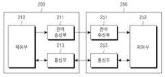
도 2는 본 발명의 실시 예에 의한 무선 전력 송신기 및 무선 전력 수신기의 블록도이다.2 is a block diagram of a wireless power transmitter and a wireless power receiver according to an embodiment of the present invention.
도 2에 도시된 바와 같이, 무선 전력 송신기(200)는 전력 송신부(211), 제어부(212) 및 통신부(213)를 포함할 수 있다. 또한 무선 전력 수신기(250)는 전력 수신부(251), 제어부(252) 및 통신부(253)를 포함할 수 있다.As illustrated in FIG. 2, the
전력 송신부(211)는 무선 전력 송신기(200)가 요구하는 전력을 제공할 수 있으며, 무선으로 무선 전력 수신기(250)에 전력을 제공할 수 있다. 여기에서, 전력 송신부(211)는 교류 파형의 형태로 전력을 공급할 수 있으며, 직류 파형의 형태로 전력을 공급하면서 이를 인버터를 이용하여 교류 파형으로 변환하여 교류 파형의 형태로 공급할 수도 있다. 전력 송신부(211)는 내장된 배터리의 형태로 구현될 수도 있으며, 또는 전력 수신 인터페이스의 형태로 구현되어 외부로부터 전력을 수신하여 다른 구성 요소에 공급하는 형태로도 구현될 수 있다. 전력 송신부(211)는 일정한 교류 파형의 전력을 제공할 수 있는 수단이라면 제한이 없다는 것은 당업자가 용이하게 이해할 것이다.The
아울러, 전력 송신부(211)는 교류 파형을 전자기파 형태로 무선 전력 수신기(250)로 제공할 수 있다. 전력 송신부(211)는 추가적으로 공진회로를 더 포함할 수 있으며, 이에 따라 소정의 전자기파를 송신 또는 수신할 수 있다. 전력 송신부(211)가 공진회로로 구현되는 경우, 공진회로의 루프 코일의 인덕턴스(L)는 변경가능할 수도 있다. 한편 전력 송신부(211)는 전자기파를 송수신할 수 있는 수단이라면 제한이 없는 것은 당업자는 용이하게 이해할 것이다.In addition, the
제어부(212)는 무선 전력 송신기(200)의 동작 전반을 제어할 수 있다. 제어부(212)는 저장부(미도시)로부터 독출한 제어에 요구되는 알고리즘, 프로그램 또는 어플리케이션을 이용하여 무선 전력 송신기(200)의 동작 전반을 제어할 수 있다. 제어부(212)는 CPU, 마이크로프로세서, 미니 컴퓨터와 같은 형태로 구현될 수 있다. 제어부(212)의 세부 동작과 관련하여서는 더욱 상세하게 후술하도록 한다.The
통신부(213)는 무선 전력 수신기(250)와 소정의 방식으로 통신을 수행할 수 있다. 통신부(213)는 무선 전력 수신기(250)의 통신부(253)와 NFC(near field communication), Zigbee 통신, 적외선 통신, 가시광선 통신, 블루투스 통신, BLE(bluetooth low energy) 방식 등을 이용하여 통신을 수행할 수 있다. 통신부(213)는 CSMA/CA 알고리즘을 이용할 수 있다. 한편, 상술한 통신 방식은 단순히 예시적인 것이며, 본원 발명은 통신부(213)에서 수행하는 특정 통신 방식에 의하여 그 권리범위가 한정되지 않는다.The
한편, 통신부(213)는 무선 전력 송신기(200)의 정보에 대한 신호를 송신할 수 있다. 여기에서, 통신부(213)는 상기 신호를 유니캐스트(unicast), 멀티캐스트(multicast) 또는 브로드캐스트(broadcast)할 수 있다. 표 1은 본 발명의 일 실시 예에 의한 무선 전력 송신기(200)로부터 송신되는 신호의 데이터 구조이다. 무선 전력 송신기(200)는 하기의 프레임을 가지는 신호를 기설정된 주기마다 송신할 수 있으며, 상기 신호는 이하에서는 Notice 신호로 명명될 수도 있다.Meanwhile, the
표 1에서의 frame type은 신호의 타입을 지시하는 필드로, 표 1에서는 해당 신호가 Notice 신호임을 지시한다. protocol version 필드는, 통신 방식의 프로토콜의 종류를 지시하는 필드로, 예를 들어 4bit가 할당될 수 있다. sequence number 필드는, 해당 신호의 순차적인 순서를 지시하는 필드로, 예를 들어 1Byte가 할당될 수 있다. sequence number는, 예를 들어 신호의 송수신 단계에 대응하여 1씩 증가될 수 있다. network ID 필드는, 무선 전력 송신기(200)의 네트워크 식별자(network ID)를 지시하는 필드로, 예를 들어 1Byte가 할당될 수 있다. Rx to Report(schedule mask) 필드는, 무선 전력 송신기(200)로 보고를 수행할 무선 전력 수신기들을 지시하는 필드로, 예를 들어 1Byte가 할당될 수 있다. 표 2는 본 발명의 일 실시 예에 의한 Rx to Report(schedule mask) 필드이다.The frame type in Table 1 is a field indicating a type of a signal, and in Table 1, a corresponding signal is a notice signal. The protocol version field is a field indicating a type of a protocol of a communication method and may be allocated, for example, 4 bits. The sequence number field is a field indicating a sequential order of the corresponding signal and may be allocated, for example, 1 byte. For example, the sequence number may be increased by one in correspondence to the transmission and reception of a signal. The network ID field is a field indicating a network ID of the
여기에서, Rx1 내지 Rx8은 무선 전력 수신기 1 내지 8에 대응할 수 있다. Rx to Report(schedule mask) 필드는 스케쥴 마스크의 번호가 1로 표시된 무선 전력 수신기가 보고를 수행하도록 구현될 수 있다.Here, Rx1 to Rx8 may correspond to
Reserved 필드는, 향후의 이용을 위하여 예약된 필드로 예를 들어 5Byte가 할당될 수 있다. Number of Rx 필드는, 무선 전력 송신기(200)의 주위의 무선 전력 수신기의 개수를 지시하는 필드로, 예를 들어 3bit가 할당될 수 있다.The Reserved field is a field reserved for future use, for example, 5 bytes may be allocated. The Number of Rx field is a field indicating the number of wireless power receivers around the
통신부(213)는 무선 전력 수신기(250)로부터 전력 정보를 수신할 수 있다. 여기에서 전력 정보는 무선 전력 수신기(250)의 용량, 배터리 잔량, 충전 횟수, 사용량, 배터리 용량, 배터리 비율 중 적어도 하나를 포함할 수 있다. 또한 통신부(213)는 무선 전력 수신기(250)의 충전 기능을 제어하는 충전 기능 제어 신호를 송신할 수 있다. 충전 기능 제어 신호는 특정 무선 전력 수신기(250)의 무선 전력 수신부(251)를 제어하여 충전 기능을 인에이블(enabled) 또는 디스에이블(disabled)하게 하는 제어 신호일 수 있다. 또는 더욱 상세하게 후술할 것으로, 전력 정보는 유선 충전 단자의 인입, SA 모드로부터 NSA 모드로의 전환, 에러 상황 해제 등의 정보를 포함할 수도 있다.The
통신부(213)는 무선 전력 수신기(250) 뿐만 아니라, 다른 무선 전력 송신기(미도시)로부터의 신호를 수신할 수도 있다. 예를 들어, 통신부(213)는 다른 무선 전력 송신기로부터 상술한 표 1의 프레임의 Notice 신호를 수신할 수 있다.The
한편, 도 2에서는 전력 송신부(211) 및 통신부(213)가 상이한 하드웨어로 구성되어 무선 전력 송신기(200)가 아웃-밴드(out-band) 형식으로 통신되는 것과 같이 도시되었지만, 이는 예시적인 것이다. 본 발명은 전력 송신부(211) 및 통신부(213)가 하나의 하드웨어로 구현되어 무선 전력 송신기(200)가 인-밴드(in-band) 형식으로 통신을 수행할 수도 있다.Meanwhile, in FIG. 2, the
무선 전력 송신기(200) 및 무선 전력 수신기(250)는 각종 신호를 송수신할 수 있으며, 이에 따라 무선 전력 송신기(200)가 주관하는 무선 전력 네트워크로의 무선 전력 수신기(250)의 가입과 무선 전력 송수신을 통한 충전 과정이 수행될 수 있으며, 상술한 과정은 더욱 상세하게 후술하도록 한다.The
도 3는 본 발명의 일 실시 예에 의한 무선 전력 송신기 및 무선 전력 수신기의 상세 블록도이다.3 is a detailed block diagram of a wireless power transmitter and a wireless power receiver according to an embodiment of the present invention.
도 3에 도시된 바와 같이, 무선 전력 송신기(200)는 전력 송신부(211), 제어부 및 통신부(212,213), 구동부(214), 증폭부(215) 및 매칭부(216)를 포함할 수 있다. 무선 전력 수신기(250)는 전력 수신부(251), 제어부 및 통신부(252,253), 정류부(254), DC/DC 컨버터부(255), 스위치부(256) 및 로드부(257)를 포함할 수 있다.As shown in FIG. 3, the
구동부(214)는 기설정된 전압 값을 가지는 직류 전력을 출력할 수 있다. 구동부(214)에서 출력되는 직류 전력의 전압 값은 제어부 및 통신부(212,213)에 의하여 제어될 수 있다.The
구동부(214)로부터 출력되는 직류 전류는 증폭부(215)로 출력될 수 있다. 증폭부(215)는 기설정된 이득으로 직류 전류를 증폭할 수 있다. 아울러, 제어부 및 통신부(212,213)로부터 입력되는 신호에 기초하여 직류 전력을 교류로 변환할 수 있다. 이에 따라, 증폭부(215)는 교류 전력을 출력할 수 있다.The DC current output from the
매칭부(216)는 임피던스 매칭을 수행할 수 있다. 예를 들어, 매칭부(216)로부터 바라본 임피던스를 조정하여, 출력 전력이 고효율 또는 고출력이 되도록 제어할 수 있다. 매칭부(216)는 제어부 및 통신부(212,213)의 제어에 기초하여 임피던스를 조정할 수 있다. 매칭부(216)는 코일 및 커패시터 중 적어도 하나를 포함할 수 있다. 제어부 및 통신부(212,213)는 코일 및 커패시터 중 적어도 하나와의 연결 상태를 제어할 수 있으며, 이에 따라 임피던스 매칭을 수행할 수 있다.The
전력 송신부(211)는 입력된 교류 전력을 전력 수신부(251)로 송신할 수 있다. 전력 송신부(211) 및 전력 수신부(251)는 동일한 공진 주파수를 가지는 공진 회로로 구현될 수 있다. 예를 들어, 공진 주파수는 6.78MHz로 결정될 수 있다.The
한편, 제어부 및 통신부(212,213)는 무선 전력 수신기(250) 측의 제어부 및 통신부(252,253)와 통신을 수행할 수 있으며, 예를 들어 양방향 2.4GHz 주파수로 통신을 수행할 수 있다.The control unit and the
한편, 전력 수신부(251)는 충전 전력을 수신할 수 있다.The
정류부(254)는 전력 수신부(251)에 수신되는 무선 전력을 직류 형태로 정류할 수 있으며, 예를 들어 브리지 다이오드의 형태로 구현될 수 있다. DC/DC 컨버터부(255)는 정류된 전력을 기설정된 이득으로 컨버팅할 수 있다. 예를 들어, DC/DC 컨버터부(255)는 출력단(259)의 전압이 5V가 되도록 정류된 전력을 컨버팅할 수 있다. 한편, DC/DC 컨버터부(255)의 전단(258)에는 인가될 수 있는 전압의 최솟값 및 최댓값이 기설정될 수 있다.The
스위치부(256)는 DC/DC 컨버터부(255) 및 로드부(257)를 연결할 수 있다. 스위치부(256)는 제어부(252)의 제어에 따라 온(on)/오프(off) 상태를 유지할 수 있다. 로드부(257)는 스위치부(256)가 온 상태인 경우에 DC/DC 컨버터부(255)로부터 입력되는 컨버팅된 전력을 저장할 수 있다.The
도 4는 본 발명의 일 실시 예에 의한 무선 전력 송신기 및 무선 전력 수신기의 동작을 설명하기 위한 흐름도이다. 도 4에 도시된 바와 같이, 무선 전력 송신기(400)는 전원을 인가할 수 있다(S401). 전원이 인가되면, 무선 전력 송신기(400)는 환경을 설정(configuration)할 수 있다(S402).4 is a flowchart illustrating an operation of a wireless power transmitter and a wireless power receiver according to an embodiment of the present invention. As shown in FIG. 4, the
무선 전력 송신기(400)는 전력 절약 모드(power save mode)에 진입할 수 있다(S403). 전력 절약 모드에서, 무선 전력 송신기(400)는 이종의 검출용 전력 비콘 각각을 각각의 주기로 인가할 수 있으며, 이에 대하여서는 도 6에서 더욱 상세하게 설명하도록 한다. 예를 들어, 도 4에서와 같이 무선 전력 송신기(400)는 검출용 전력 비콘(power beacon)(404,405)를 인가할 수 있으며, 검출용 전력 비콘들(404,405) 각각의 전력 값의 크기는 상이할 수도 있다. 검출용 전력 비콘들(404,405) 중 일부 또는 전부는 무선 전력 수신기(450)의 통신부를 구동할 수 있는 전력량을 가질 수 있다. 예를 들어, 무선 전력 수신기(450)는 검출용 전력 비콘들(404,405) 중 일부 또는 전부에 의하여 통신부를 구동시켜 무선 전력 송신기(400)와 통신을 수행할 수 있다. 상기 상태를 널(Null) 상태로 명명할 수 있다.The
무선 전력 송신기(400)는 무선 전력 수신기(450)의 배치에 의한 로드 변경을 검출할 수 있다. 무선 전력 송신기(400)는 저전력 모드(S409)로 진입할 수 있다. 저전력 모드에 대하여서도 도 6을 참조하여 더욱 상세하게 설명하도록 한다. 한편, 무선 전력 수신기(450)는 무선 전력 송신기(400)로부터 수신된 전력에 기초하여 통신부를 구동시킬 수 있다(S409).The
무선 전력 수신기(450)는 무선 전력 송신기(400)로 무선 전력 송신기 검색 (PTU searching)신호를 송신할 수 있다(S410). 무선 전력 수신기(450)는 BLE 기반의 애드버타이즈먼트(Advertisement) 신호로서, 무선 전력 송신기 검색 신호를 송신할 수 있다. 무선 전력 수신기(450)는 무선 전력 송신기 검색 신호를 주기적으로 송신할 수 있으며, 무선 전력 송신기(400)로부터 응답 신호를 수신하거나 또는 기설정된 시간이 도래할 때까지 송신할 수 있다.The
무선 전력 수신기(450)로부터 무선 전력 송신기 검색 신호가 수신되면, 무선 전력 송신기(400)는 응답 신호(PRU Respnse) 신호를 송신할 수 있다(S411). 여기에서 응답 신호는 무선 전력 송신기(400) 및 무선 전력 수신기(400) 사이의 연결(connection)을 형성(form)할 수 있다.When the wireless power transmitter search signal is received from the
무선 전력 수신기(450)는 PRU static 신호를 송신할 수 있다(S412). 여기에서, PRU static 신호는 무선 전력 수신기(450)의 상태를 지시하는 신호일 수 있으며, 무선 전력 송신기(400)가 관제하는 무선 전력 네트워크에 가입을 요청할 수 있다.The
무선 전력 송신기(400)는 PTU static 신호를 송신할 수 있다(S413). 무선 전력 송신기(400)가 송신하는 PTU static 신호는 무선 전력 송신기(400)의 캐퍼빌리티(capability)를 지시하는 신호일 수 있다.The
무선 전력 송신기(400) 및 무선 전력 수신기(450)가 PRU static 신호 및 PTU static 신호를 송수신하면, 무선 전력 수신기(450)는 무선 전력 수신기 다이내믹(PRU Dynamic) 신호를 주기적으로 송신할 수 있다(S414,S415). 무선 전력 수신기 다이내믹(PRU Dynamic) 신호는 무선 전력 수신기(450)에서 측정된 적어도 하나의 파라미터 정보를 포함할 수 있다. 예를 들어, 무선 전력 수신기 다이내믹(PRU Dynamic) 신호는 무선 전력 수신기(450)의 정류부 후단의 전압 정보를 포함할 수 있다. 상기 무선 전력 수신기(450)의 상태를 부트(Boot) 상태라고 명명할 수 있다.When the
무선 전력 송신기(400)는 전력 송신 모드로 진입하고(S416), 무선 전력 송신기(400)는 무선 전력 수신기(450)가 충전을 수행하도록 하는 명령 신호인 무선 전력 수신기 명령(PRU command) 신호를 송신할 수 있다(S417). 전력 송신 모드에서, 무선 전력 송신기(400)는 충전 전력을 송신할 수 있다.The
무선 전력 송신기(400)가 송신하는 무선 전력 수신기 명령 신호는 무선 전력 수신기(450)의 충전을 인에이블/디스에이블하는 정보 및 허여(permission) 정보를 포함할 수 있다. 무선 전력 수신기 명령 신호는 무선 전력 송신기(400)가 무선 전력 수신기(450)의 상태를 변경하도록 하는 경우에 송신하거나 또는 기설정된 주기, 예를 들어 250ms의 주기로 송신될 수도 있다. 무선 전력 수신기(400)는 무선 전력 수신기 명령 신호에 따라서 설정을 변경하고, 무선 전력 수신기(450)의 상태를 보고하기 위한 무선 전력 수신기 다이내믹(PRU Dynamic) 신호를 송신할 수 있다(S418,S419). 무선 전력 수신기(450)가 송신하는 무선 전력 수신기 다이내믹(PRU Dynamic) 신호는 전압, 전류, 무선 전력 수신기 상태 및 온도 정보 중 적어도 하나를 포함할 수 있다. 상기 무선 전력 수신기(450)의 상태를 On 상태로 명명할 수 있다.The wireless power receiver command signal transmitted by the
한편, 무선 전력 수신기 다이내믹(PRU Dynamic) 신호는 표 3과 같은 데이터 구조를 가질 수 있다.On the other hand, the wireless power receiver dynamic (PRU Dynamic) signal may have a data structure as shown in Table 3.
무선 전력 수신기 다이내믹(PRU Dynamic) 신호는, 표 3에서와 같이 선택적 필드 정보, 무선 전력 수신기의 정류부의 후단의 전압 정보, 무선 전력 수신기의 정류부의 후단의 전류 정보, 무선 전력 수신기의 DC/DC 컨버터의 후단의 전압 정보, 무선 전력 수신기의 DC/DC 컨버터의 후단의 전류 정보, 온도 정보, 무선 전력 수신기의 정류부의 후단의 최소 전압값 정보, 무선 전력 수신기의 정류부의 후단의 최적 전압값 정보, 무선 전력 수신기의 정류부의 후단의 최대 전압값 정보 및 경고 정보 중 적어도 하나를 포함할 수 있다.The wireless power receiver dynamic (PRU) dynamic signal may include optional field information, voltage information at the rear end of the rectifier of the wireless power receiver, current information at the rear end of the rectifier of the wireless power receiver, and a DC / DC converter of the wireless power receiver, as shown in Table 3. Voltage information at the rear end of the wireless power receiver, current information at the rear end of the DC / DC converter of the wireless power receiver, temperature information, minimum voltage value information at the rear end of the rectifier of the wireless power receiver, optimum voltage value information at the rear end of the rectifier of the wireless power receiver, and wireless It may include at least one of the maximum voltage value information and warning information of the rear end of the rectifier of the power receiver.
경고 정보는 하기의 표 4와 같은 데이터 구조로 형성될 수 있다.The alert information may be formed in a data structure as shown in Table 4 below.
경고 정보는, 표 4와 같이 과전압(over voltage), 과전류(over current), 과온도(over temperature), 충전 완료(charge complete), 유선 충전 단자 인입 감지(TA detect), SA 모드/ NSA 모드 전환(transition), 재충전 요청(restart request) 등을 포함할 수 있다.The warning information is shown in Table 4, over voltage, over current, over temperature, charge complete, wired terminal detection (TA detect), SA mode / NSA mode switching. It may include a transition, a restart request, and the like.
무선 전력 수신기(450)는 무선 전력 수신기 명령 신호를 수신하여 충전을 수행할 수 있다. 예를 들어, 무선 전력 송신기(400)는 무선 전력 수신기(450)를 충전하기에 충분한 전력을 가지는 경우 충전을 인에이블하도록 하는 무선 전력 수신기 명령 신호를 송신할 수 있다. 한편, 무선 전력 수신기 명령 신호는 충전 상태가 변경될 때마다 송신될 수 있다. 무선 전력 수신기 명령 신호는 예를 들어 250ms 마다 송신될 수 있거나, 파라미터 변경이 있을 때 송신될 수 있다. 무선 전력 수신기 명령 신호는 파라미터가 변경되지 않더라도 기설정된 임계 시간, 예를 들어 1초 이내에는 송신되어야 하도록 설정될 수도 있다.The
한편, 무선 전력 수신기(450)는 에러 발생을 감지할 수 있다. 무선 전력 수신기(450)는 경고 신호를 무선 전력 송신기(400)로 송신할 수 있다(S420). 경고 신호는 무선 전력 수신기 다이내믹(PRU Dynamic) 신호로 송신되거나 또는 경고(alert) 신호로 송신할 수 있다. 예를 들어, 무선 전력 수신기(450)는 표 3의 PRU alert 필드에 에러 상황을 반영하여 무선 전력 송신기(400)로 송신할 수 있다. 또는 무선 전력 수신기(450)는 에러 상황을 지시하는 단독 경고 신호를 무선 전력 송신기(400)로 송신할 수도 있다. 무선 전력 송신기(400)는 경고 신호를 수신하면, 래치 실패 모드로 진입할 수 있다(S422). 무선 전력 수신기(450)는 널 상태로 진입할 수 있다(S423).Meanwhile, the
도 5는 본 발명의 다른 실시 예에 의한 무선 전력 송신기 및 무선 전력 수신기의 동작을 설명하는 흐름도이다. 도 5의 제어 방법은 도 6을 참조하여 더욱 상세하게 설명하도록 한다. 도 6은 도 5의 실시 예에 의한 무선 전력 송신기가 인가하는 전력량의 시간 축에 대한 그래프이다.5 is a flowchart illustrating an operation of a wireless power transmitter and a wireless power receiver according to another embodiment of the present invention. The control method of FIG. 5 will be described in more detail with reference to FIG. 6. 6 is a graph of a time axis of the amount of power applied by the wireless power transmitter according to the embodiment of FIG. 5.
도 5에 도시된 바와 같이, 무선 전력 송신기는 구동을 개시할 수 있다(S501). 아울러, 무선 전력 송신기는 초기 설정을 리셋할 수 있다(S503). 무선 전력 송신기는 전력 절약 모드에 진입할 수 있다(S505). 여기에서, 전력 절약 모드는, 무선 전력 송신기가 전력 송신부에 전력량이 상이한 이종의 전력을 인가하는 구간일 수 있다. 예를 들어, 무선 전력 송신기는 도 6에서의 제 2 검출 전력(601,602) 및 제 3 검출 전력(611,612,613,614,615)을 전력 송신부에 인가하는 구간일 수 있다. 여기에서, 무선 전력 송신기는 제 2 검출 전력(601,602)을 제 2 주기로 주기적으로 인가할 수 있으며, 제 2 검출 전력(601,602)을 인가하는 경우에는 제 2 기간 동안 인가할 수 있다. 무선 전력 송신기는 제 3 검출 전력(611,612,613,614,615)을 제 3 주기로 주기적으로 인가할 수 있으며, 제 3 검출 전력(611,612,613,614,615)을 인가하는 경우에는 제 3 기간 동안 인가할 수 있다. 한편, 제 3 검출 전력(611,612,613,614,615)의 각각의 전력 값은 상이한 것과 같이 도시되어 있지만, 제 3 검출 전력(611,612,613,614,615)의 각각의 전력 값은 상이할 수도 있으며 또는 동일할 수도 있다.As shown in FIG. 5, the wireless power transmitter may start driving (S501). In addition, the wireless power transmitter may reset the initial setting (S503). The wireless power transmitter may enter a power saving mode (S505). Here, the power saving mode may be a section in which the wireless power transmitter applies heterogeneous powers of different power amounts to the power transmitter. For example, the wireless power transmitter may be a section for applying the second detection power 601, 602 and the third detection power 611, 612, 613, 614, 615 in FIG. 6 to the power transmitter. In this case, the wireless power transmitter may periodically apply the second detection power 601, 602 at a second cycle, and apply the second detection power 601, 602 during the second period. The wireless power transmitter may periodically apply the third detection power 611, 612, 613, 614, 615 at a third cycle, and apply the third detection power 611, 612, 613, 614, 615 for a third period of time. Meanwhile, although the respective power values of the third detection powers 611, 612, 613, 614, 615 are shown as being different, the respective power values of the third detection powers 611, 612, 613, 614, 615 may be different or the same.
무선 전력 송신기는 제 3 검출 전력(611)을 출력한 이후에 동일한 크기의 전력량을 가지는 제 3 검출 전력(612)을 출력할 수 있다. 상기와 같이 무선 전력 송신기가 동일한 크기의 제 3 검출 전력을 출력하는 경우, 제 3 검출 전력의 전력량은 가장 소형의 무선 전력 수신기, 예를 들어 카테고리 1의 무선 전력 수신기를 검출할 수 있는 전력량을 가질 수 있다.The wireless power transmitter may output the third detection power 612 having the same amount of power after outputting the third detection power 611. When the wireless power transmitter outputs the third detection power of the same size as described above, the amount of power of the third detection power has the amount of power capable of detecting the smallest wireless power receiver, for example, the
무선 전력 송신기는 제 3 검출 전력(611)을 출력한 이후에 상한 크기의 전력량을 가지는 제 3 검출 전력(612)을 출력할 수 있다. 상기와 같이 무선 전력 송신기가 상이한 크기의 제 3 검출 전력을 출력하는 경우, 제 3 검출 전력의 전력량 각각은 카테고리 1 내지 5의 무선 전력 수신기를 검출할 수 있는 전력량일 수 있다. 예를 들어, 제 3 검출 전력(611)는 카테고리 5의 무선 전력 수신기를 검출할 수 있는 전력량을 가질 수 있으며, 제 3 검출 전력(612)는 카테고리 3의 무선 전력 수신기를 검출할 수 있는 전력량을 가질 수 있으며, 제 3 검출 전력(613)는 카테고리 1의 무선 전력 수신기를 검출할 수 있는 전력량을 가질 수 있다.The wireless power transmitter may output the third detection power 612 having the upper limit amount of power after the third detection power 611 is output. When the wireless power transmitter outputs third detection power having different magnitudes as described above, each of the power amounts of the third detection power may be an amount of power capable of detecting the wireless power receivers of the
한편, 제 2 검출 전력(601,602)은 무선 전력 수신기를 구동시킬 수 있는 전력일 수 있다. 더욱 상세하게는, 제 2 검출 전력(601,602)은 무선 전력 수신기의 제어부 및 통신부를 구동시킬 수 있는 전력량을 가질 수 있다.Meanwhile, the second detection powers 601 and 602 may be power capable of driving the wireless power receiver. In more detail, the second detection powers 601 and 602 may have a power amount capable of driving the control unit and the communication unit of the wireless power receiver.
무선 전력 송신기는 제 2 검출 전력(601,602) 및 제 3 검출 전력(611,612,613,614,615)을 전력 수신부로 각각 제 2 주기 및 제 3 주기로 인가할 수 있다. 무선 전력 송신기 상에 무선 전력 수신기가 배치되는 경우, 무선 전력 송신기의 일 지점에서 바라보는 임피던스가 변경될 수 있다. 무선 전력 송신기는 제 2 검출 전력(601,602) 및 제 3 검출 전력(611,612,613,614,615)이 인가되는 중 임피던스 변경을 검출할 수 있다. 예를 들어, 무선 전력 송신기는 제 3 검출 전력(615)을 인가하는 중, 임피던스가 변경되는 것을 검출할 수 있다. 이에 따라, 무선 전력 송신기는 물체를 검출할 수 있다(S507). 물체가 검출되지 않는 경우에는(S507-N), 무선 전력 송신기는 이종의 전력을 주기적으로 인가하는 전력 절약 모드를 유지할 수 있다(S505).The wireless power transmitter may apply the second detection power 601, 602 and the third detection power 611, 612, 613, 614, 615 to the power receiver in a second cycle and a third cycle, respectively. When the wireless power receiver is disposed on the wireless power transmitter, the impedance viewed at one point of the wireless power transmitter may be changed. The wireless power transmitter may detect a change in impedance while the second detection power 601, 602 and the third detection power 611, 612, 613, 614, 615 are applied. For example, the wireless power transmitter may detect that the impedance is changed while applying the third detection power 615. Accordingly, the wireless power transmitter may detect an object (S507). If no object is detected (S507-N), the wireless power transmitter may maintain a power saving mode in which heterogeneous power is periodically applied (S505).
한편, 임피던스가 변경되어 물체가 검출되는 경우에는(S507-Y), 무선 전력 송신기는 저전력 모드로 진입할 수 있다. 여기에서, 저전력 모드는 무선 전력 송신기가 무선 전력 수신기의 제어부 및 통신부를 구동시킬 수 있는 전력량을 가진 구동 전력을 인가하는 모드이다. 예를 들어 도 6에서는, 무선 전력 송신기는 구동 전력(620)을 전력 송신부에 인가할 수 있다. 무선 전력 수신기는 구동 전력(620)을 수신하여 제어부 및 통신부를 구동할 수 있다. 무선 전력 수신기는 구동 전력(620)에 기초하여 무선 전력 송신기와 소정의 방식에 기초하여 통신을 수행할 수 있다. 예를 들어, 무선 전력 수신기는 인증에 요구되는 데이터를 송수신할 수 있으며, 이에 기초하여 무선 전력 송신기가 관장하는 무선 전력 네트워크에 가입할 수 있다. 다만, 무선 전력 수신기가 아닌 이물질이 배치되는 경우에는, 데이터 송수신이 수행될 수 없다. 이에 따라, 무선 전력 송신기는 배치된 물체가 이물질인지 여부를 결정할 수 있다(S511). 예를 들어, 무선 전력 송신기는 기설정된 시간 동안 물체로부터 응답을 수신하지 못한 경우, 물체를 이물질로 결정할 수 있다.On the other hand, when the impedance is changed to detect the object (S507-Y), the wireless power transmitter may enter the low power mode. Here, the low power mode is a mode in which the wireless power transmitter applies driving power having an amount of power capable of driving the controller and the communication unit of the wireless power receiver. For example, in FIG. 6, the wireless power transmitter may apply driving power 620 to the power transmitter. The wireless power receiver may receive the driving power 620 to drive the control unit and the communication unit. The wireless power receiver may communicate with the wireless power transmitter based on a predetermined scheme based on the driving power 620. For example, the wireless power receiver may transmit and receive data required for authentication, and may join the wireless power network managed by the wireless power transmitter based on this. However, when a foreign material other than the wireless power receiver is disposed, data transmission and reception may not be performed. Accordingly, the wireless power transmitter may determine whether the placed object is a foreign object (S511). For example, if the wireless power transmitter does not receive a response from the object for a predetermined time, the wireless power transmitter may determine the object as a foreign object.
이물질로 결정된 경우에는(S511-Y), 무선 전력 송신기는 랫치 실패 모드로 진입할 수 있다. 예를 들면, 무선 전력 송신기는 도 6에서의 제 1 전력(631 내지 634)을 제 1 주기로 주기적으로 인가할 수 있다. 무선 전력 송신기는 제 1 전력을 인가하는 중에 임피던스 변경을 검출할 수 있다. 예를 들어, 이물질이 회수되는 경우에는 임피던스 변경을 검출할 수 있으며, 무선 전력 송신기는 이물질이 회수된 것으로 판단할 수 있다. 또는 이물질이 회수되지 않는 경우에는, 무선 전력 송신기는 임피던스 변경을 검출할 수 없으며, 무선 전력 송신기는 이물질이 회수되지 않은 것으로 판단할 수 있다. 이물질이 회수되지 않는 경우에는, 무선 전력 송신기는 램프 및 경고음 중 적어도 하나를 출력하여 현재의 무선 전력 송신기의 상태가 에러 상태임을 사용자에게 알릴 수 있다. 이에 따라, 무선 전력 송신기는 램프 및 경고음 중 적어도 하나를 출력하는 출력부를 포함할 수 있다.If it is determined that the foreign matter (S511-Y), the wireless power transmitter may enter the latch failure mode. For example, the wireless power transmitter may periodically apply the first power 631 to 634 in FIG. 6 at a first cycle. The wireless power transmitter may detect a change in impedance while applying the first power. For example, when the foreign matter is recovered, the impedance change may be detected, and the wireless power transmitter may determine that the foreign matter has been recovered. Alternatively, when the foreign matter is not recovered, the wireless power transmitter cannot detect the impedance change, and the wireless power transmitter may determine that the foreign matter is not recovered. If the foreign matter is not recovered, the wireless power transmitter may output at least one of a lamp and a warning sound to notify the user that the current wireless power transmitter is in an error state. Accordingly, the wireless power transmitter may include an output unit for outputting at least one of a lamp and a warning sound.
이물질이 회수되지 않은 것으로 판단되는 경우(S515-N), 무선 전력 송신기는 랫치 실패 모드를 유지할 수 있다(S513). 한편, 이물질이 회수된 것으로 판단되는 경우(S515-Y), 무선 전력 송신기는 전력 절약 모드로 재진입할 수 있다(S517). 예를 들어, 무선 전력 송신기는 도 5의 제 2 전력(651,652) 및 제 3 전력(661 내지 665)을 인가할 수 있다.If it is determined that the foreign matter has not been recovered (S515-N), the wireless power transmitter may maintain the latch failure mode (S513). On the other hand, if it is determined that the foreign matter is recovered (S515-Y), the wireless power transmitter may re-enter the power saving mode (S517). For example, the wireless power transmitter may apply the second power 651 and 652 and the third power 661 to 665 of FIG. 5.
상술한 바와 같이, 무선 전력 송신기는, 무선 전력 수신기가 아닌 이물질이 배치된 경우에 랫치 실패 모드로 진입할 수 있다. 아울러, 무선 전력 송신기는 랫치 실패 모드에서 인가하는 전력에 기초한 임피던스 변경에 의거하여 이물질의 회수 여부를 판단할 수 있다. 즉, 도 5 및 6의 실시 예에서의 랫치 실패 모드 진입 조건은 이물질의 배치일 수 있다. 한편, 무선 전력 송신기는 이물질의 배치 이외에도 다양한 랫치 실패 모드 진입 조건을 가질 수 있다. 예를 들어, 무선 전력 송신기는 배치된 무선 전력 수신기와 교차 연결될 수 있으며, 상기의 경우에서도 랫치 실패 모드로 진입될 수 있다.As described above, the wireless power transmitter may enter the latch failure mode when a foreign material other than the wireless power receiver is disposed. In addition, the wireless power transmitter may determine whether to collect the foreign matter based on the impedance change based on the power applied in the latch failure mode. That is, the latch failure mode entry condition in the embodiments of FIGS. 5 and 6 may be a batch of foreign matter. On the other hand, the wireless power transmitter may have various latch failure mode entry conditions in addition to the placement of the foreign matter. For example, the wireless power transmitter may be cross-connected with the deployed wireless power receiver and may enter the latch failure mode even in this case.
이에 따라, 무선 전력 송신기는 교차 연결 발생 시, 초기 상태로의 복귀가 요구되며, 무선 전력 수신기의 회수가 요구된다. 무선 전력 송신기는 다른 무선 전력 송신기상에 배치되는 무선 전력 수신기가 무선 전력 네트워크에 가입되는 교차 연결을 랫치 실패 모드 진입 조건으로 설정할 수 있다. 교차 연결을 포함하는 에러 발생 시의 무선 전력 송신기의 동작을 도 7을 참조하여 설명하도록 한다.Accordingly, the wireless power transmitter is required to return to the initial state when the cross connection occurs, and the number of times of the wireless power receiver is required. The wireless power transmitter may set a cross connection in which a wireless power receiver disposed on another wireless power transmitter joins the wireless power network as a latch failure mode entry condition. An operation of the wireless power transmitter at the time of the error including the cross connection will be described with reference to FIG. 7.
도 7은 본 발명의 일 실시 예에 의한 무선 전력 송신기의 제어 방법을 설명하는 흐름도이다. 도 7의 제어 방법은 도 8을 참조하여 더욱 상세하게 설명하도록 한다. 도 8은 도 7의 실시 예에 의한 무선 전력 송신기가 인가하는 전력량의 시간 축에 대한 그래프이다.7 is a flowchart illustrating a control method of a wireless power transmitter according to an embodiment of the present invention. The control method of FIG. 7 will be described in more detail with reference to FIG. 8. FIG. 8 is a graph of a time axis of power applied by a wireless power transmitter according to the embodiment of FIG. 7.
무선 전력 송신기는 구동을 개시할 수 있다(S701). 아울러, 무선 전력 송신기는 초기 설정을 리셋할 수 있다(S703). 무선 전력 송신기는 전력 절약 모드에 진입할 수 있다(S705). 여기에서, 전력 절약 모드는, 무선 전력 송신기가 전력 송신부에 전력량이 상이한 이종의 전력을 인가하는 구간일 수 있다. 예를 들어, 무선 전력 송신기는 도 8에서의 제 2 검출 전력(801,802) 및 제 3 검출 전력(811,812,813,814,815)을 전력 송신부에 인가하는 구간일 수 있다. 여기에서, 무선 전력 송신기는 제 2 검출 전력(801,802)을 제 2 주기로 주기적으로 인가할 수 있으며, 제 2 검출 전력(801,802)을 인가하는 경우에는 제 2 기간 동안 인가할 수 있다. 무선 전력 송신기는 제 3 검출 전력(811,812,813,814,815)을 제 3 주기로 주기적으로 인가할 수 있으며, 제 3 검출 전력(811,812,813,814,815)을 인가하는 경우에는 제 3 기간 동안 인가할 수 있다. 한편, 제 3 검출 전력(811,812,813,814,815)의 각각의 전력 값은 상이한 것과 같이 도시되어 있지만, 제 3 검출 전력(811,812,813,814,815)의 각각의 전력 값은 상이할 수도 있으며 또는 동일할 수도 있다.The wireless power transmitter may start driving (S701). In addition, the wireless power transmitter may reset the initial setting (S703). The wireless power transmitter may enter a power saving mode (S705). Here, the power saving mode may be a section in which the wireless power transmitter applies heterogeneous powers of different power amounts to the power transmitter. For example, the wireless power transmitter may be a section for applying the
한편, 제 2 검출 전력(801,802)은 무선 전력 수신기를 구동시킬 수 있는 전력일 수 있다. 더욱 상세하게는, 제 2 검출 전력(801,802)은 무선 전력 수신기의 제어부 및 통신부를 구동시킬 수 있는 전력량을 가질 수 있다.Meanwhile, the
무선 전력 송신기는 제 2 검출 전력(801,802) 및 제 3 검출 전력(811,812,813,814,815)을 전력 수신부로 각각 제 2 주기 및 제 3 주기로 인가할 수 있다. 무선 전력 송신기 상에 무선 전력 수신기가 배치되는 경우, 무선 전력 송신기의 일 지점에서 바라보는 임피던스가 변경될 수 있다. 무선 전력 송신기는 제 2 검출 전력(801,802) 및 제 3 검출 전력(811,812,813,814,815)이 인가되는 중 임피던스 변경을 검출할 수 있다. 예를 들어, 무선 전력 송신기는 제 3 검출 전력(815)을 인가하는 중, 임피던스가 변경되는 것을 검출할 수 있다. 이에 따라, 무선 전력 송신기는 물체를 검출할 수 있다(S707). 물체가 검출되지 않는 경우에는(S707-N), 무선 전력 송신기는 이종의 전력을 주기적으로 인가하는 전력 절약 모드를 유지할 수 있다(S705).The wireless power transmitter may apply the
한편, 임피던스가 변경되어 물체가 검출되는 경우에는(S807-Y), 무선 전력 송신기는 저전력 모드로 진입할 수 있다(S809). 여기에서, 저전력 모드는 무선 전력 송신기가 무선 전력 수신기의 제어부 및 통신부를 구동시킬 수 있는 전력량을 가진 구동 전력을 인가하는 모드이다. 예를 들어 도 8에서는, 무선 전력 송신기는 구동 전력(820)을 전력 송신부에 인가할 수 있다. 무선 전력 수신기는 구동 전력(820)을 수신하여 제어부 및 통신부를 구동할 수 있다. 무선 전력 수신기는 구동 전력(820)에 기초하여 무선 전력 송신기와 소정의 방식에 기초하여 통신을 수행할 수 있다. 예를 들어, 무선 전력 수신기는 인증에 요구되는 데이터를 송수신할 수 있으며, 이에 기초하여 무선 전력 송신기가 관장하는 무선 전력 네트워크에 가입할 수 있다.On the other hand, if the object is detected by changing the impedance (S807-Y), the wireless power transmitter may enter the low power mode (S809). Here, the low power mode is a mode in which the wireless power transmitter applies driving power having an amount of power capable of driving the controller and the communication unit of the wireless power receiver. For example, in FIG. 8, the wireless power transmitter may apply the driving
이후, 무선 전력 송신기는 충전 전력을 송신하는 전력 송신 모드로 진입할 수 있다(S711). 예를 들어, 무선 전력 송신기는 도 8에서와 같이 충전 전력(821)을 인가할 수 있으며, 충전 전력은 무선 전력 수신기로 송신될 수 있다.Thereafter, the wireless power transmitter may enter a power transmission mode for transmitting charging power (S711). For example, the wireless power transmitter may apply charging
무선 전력 송신기는 전력 송신 모드에서, 에러가 발생하는지 여부를 판단할 수 있다. 여기에서, 에러는 무선 전력 송신기 상에 이물질이 배치되는 것, 교차 연결, 과전압(over voltage), 과전류(over current), 과온도(over temperature) 등일 수 있다. 무선 전력 송신기는 과전압(over voltage), 과전류(over current), 과온도(over temperature) 등을 측정할 수 있는 센싱부를 포함할 수 있다. 예를 들어, 무선 전력 송신기는 기준 지점의 전압 또는 전류를 측정할 수 있으며, 측정된 전압 또는 전류가 임계치를 초과하는 것을 과전압 또는 과전류 조건이 충족되는 것으로 판단할 수 있다. 또는 무선 전력 송신기는 온도 센싱 수단을 포함할 수 있으며, 온도 센싱 수단은 무선 전력 송신기의 기준 지점의 온도를 측정할 수 있다. 기준 지점의 온도가 임계치를 초과하는 경우에는, 무선 전력 송신기는 과온도 조건이 충족된 것으로 판단할 수 있다.The wireless power transmitter may determine whether an error occurs in the power transmission mode. Here, the error may be a foreign material disposed on the wireless power transmitter, cross connection, over voltage, over current, over temperature, and the like. The wireless power transmitter may include a sensing unit capable of measuring over voltage, over current, over temperature, and the like. For example, the wireless power transmitter may measure the voltage or current at the reference point, and may determine that the overvoltage or overcurrent condition is satisfied that the measured voltage or current exceeds the threshold. Alternatively, the wireless power transmitter may include a temperature sensing means, and the temperature sensing means may measure a temperature of a reference point of the wireless power transmitter. If the temperature at the reference point exceeds the threshold, the wireless power transmitter may determine that the overtemperature condition is met.
도 8의 실시 예에서는, 무선 전력 송신기 상에 이물질이 추가적으로 배치되는 에러가 도시되었지만, 에러는 이에 한정되지 않으며 이물질이 배치되는 것, 교차 연결, 과전압(over voltage), 과전류(over current), 과온도(over temperature)에 대하여서도 무선 전력 송신기가 유사한 과정으로 동작함을 당업자는 용이하게 이해할 수 있을 것이다.In the embodiment of FIG. 8, an error in which an alien substance is additionally disposed on the wireless power transmitter is illustrated, but the error is not limited thereto, and the foreign substance is disposed, cross connection, over voltage, over current, and Those skilled in the art will readily appreciate that the wireless power transmitter operates in a similar process with respect to over temperature.
에러가 발생하지 않으면(S713-N), 무선 전력 송신기는 전력 송신 모드를 유지할 수 있다(S711). 한편, 에러가 발생하면(S713-Y), 무선 전력 송신기는 랫치 실패 모드로 진입할 수 있다(S715). 예를 들어, 무선 전력 송신기는 도 8과 같이 제 1 전력(831 내지 835)를 인가할 수 있다. 아울러, 무선 전력 송신기는 랫치 실패 모드 동안 램프 및 경고음 중 적어도 하나를 포함한 에러 발생 표시를 출력할 수 있다. 이물질 또는 무선 전력 수신기가 회수되지 않은 것으로 판단되는 경우(S717-N), 무선 전력 송신기는 랫치 실패 모드를 유지할 수 있다(S715). 한편, 이물질 또는 무선 전력 수신기가 회수된 것으로 판단되는 경우(S717-Y), 무선 전력 송신기는 전력 절약 모드로 재진입할 수 있다(S719). 예를 들어, 무선 전력 송신기는 도 8의 제 2 전력(851,852) 및 제 3 전력(861 내지 865)을 인가할 수 있다.If no error occurs (S713-N), the wireless power transmitter may maintain the power transmission mode (S711). On the other hand, if an error occurs (S713-Y), the wireless power transmitter may enter the latch failure mode (S715). For example, the wireless power transmitter may apply the
이상에서, 무선 전력 송신기가 충전 전력을 송신하는 중 에러가 발생한 경우의 동작에 대하여 설명하였다. 이하에서는, 무선 전력 송신기 상에 복수의 무선 전력 수신기가 충전 전력을 수신하는 경우의 동작에 대하여 설명하도록 한다.In the above, the operation when an error occurs while the wireless power transmitter is transmitting the charging power has been described. Hereinafter, an operation when a plurality of wireless power receivers receive charging power on the wireless power transmitter will be described.
도 9는 본 발명의 일 실시 예에 의한 무선 전력 송신기의 제어 방법을 설명하기 위한 흐름도이다. 도 9의 제어 방법은 도 10을 참조하여 더욱 상세하게 설명하도록 한다. 도 10은 도 9의 실시 예에 의한 무선 전력 송신기가 인가하는 전력량의 시간 축에 대한 그래프이다.9 is a flowchart illustrating a control method of a wireless power transmitter according to an embodiment of the present invention. The control method of FIG. 9 will be described in more detail with reference to FIG. 10. FIG. 10 is a graph of a time axis of a power amount applied by the wireless power transmitter according to the embodiment of FIG. 9.
도 9에 도시된 바와 같이, 무선 전력 송신기는 제 1 무선 전력 수신기로 충전 전력을 송신할 수 있다(S901). 아울러, 무선 전력 송신기는 추가적으로 제 2 무선 전력 수신기를 무선 전력 네트워크로 가입시킬 수 있다(S903). 또한 무선 전력 송신기는 제 2 무선 전력 수신기에도 충전 전력을 송신할 수 있다(S905). 더욱 상세하게는, 무선 전력 송신기는 제 1 무선 전력 수신기 및 제 2 무선 전력 수신기가 요구하는 충전 전력의 합계를 전력 수신부에 인가할 수 있다.As shown in FIG. 9, the wireless power transmitter may transmit charging power to the first wireless power receiver (S901). In addition, the wireless power transmitter may additionally subscribe the second wireless power receiver to the wireless power network (S903). In addition, the wireless power transmitter may transmit charging power to the second wireless power receiver (S905). More specifically, the wireless power transmitter may apply the sum of charging powers required by the first wireless power receiver and the second wireless power receiver to the power receiver.
도 10에서는 상기의 S901 단계 내지 S905 단계에 대한 일 실시 예가 도시된다. 예를 들어 무선 전력 송신기는 제 2 검출 전력(1001,1002) 및 제 3 검출 전력(1011 내지 1015)을 인가하는 전력 절약 모드를 유지할 수 있다. 이후, 무선 전력 송신기는 제 1 무선 전력 수신기를 검출하고, 검출 전력(1020)을 유지하는 저전력 모드로 진입할 수 있다. 이후, 무선 전력 송신기는 제 1 충전 전력(1030)을 인가하는 전력 송신 모드로 진입할 수 있다. 무선 전력 송신기는 제 2 무선 전력 수신기를 검출할 수 있으며, 제 2 무선 전력 수신기를 무선 전력 네트워크에 가입시킬 수 있다. 아울러, 무선 전력 송신기는 제 1 무선 전력 수신기 및 제 2 무선 전력 수신기가 요구하는 전력량의 합계의 전력량을 가지는 제 2 충전 전력(1040)을 인가할 수 있다.10 illustrates an embodiment of the above steps S901 to S905. For example, the wireless power transmitter may maintain a power saving mode in which the
다시 도 9를 참조하면, 무선 전력 송신기는 제 1 및 제 2 무선 전력 수신기 양자에 충전 전력을 송신하는 중(S905), 에러 발생을 검출할 수 있다(S907). 여기에서, 에러는 상술한 바와 같이, 이물질 배치, 교차 연결, 과전압(over voltage), 과전류(over current), 과온도(over temperature) 등일 수 있다. 에러가 발생하지 않으면(S907-N), 무선 전력 송신기는 제 2 충전 전력(1040)의 인가를 유지할 수 있다.Referring back to FIG. 9, the wireless power transmitter may detect an error occurrence while transmitting charging power to both the first and second wireless power receivers (S905). Here, the error may be a foreign material arrangement, cross connection, over voltage, over current, over temperature, and the like, as described above. If no error occurs (S907-N), the wireless power transmitter may maintain application of the
한편, 에러가 발생하면(S907-Y), 무선 전력 송신기는 랫치 실패 모드로 진입할 수 있다(S909). 예를 들어, 무선 전력 송신기는 도 10의 제 1 전력(1051 내지 1055)를 제 1 주기로 인가할 수 있다. 무선 전력 송신기는 제 1 무선 전력 수신기 및 제 2 무선 전력 수신기 모두가 회수되는지를 판단할 수 있다(S911). 예를 들어, 무선 전력 송신기는 제 1 전력(1051 내지 1055)의 인가 중 임피던스 변경을 검출할 수 있다. 무선 전력 송신기는 임피던스가 초기 수치로 복귀하는지 여부에 기초하여 제 1 무선 전력 수신기 및 제 2 무선 전력 수신기 모두가 회수되는지를 판단할 수 있다.On the other hand, if an error occurs (S907-Y), the wireless power transmitter may enter the latch failure mode (S909). For example, the wireless power transmitter may apply the
제 1 무선 전력 수신기 및 제 2 무선 전력 수신기 모두가 회수된 것으로 판단되면(S911-Y), 무선 전력 송신기는 전력 절약 모드로 진입할 수 있다(S913). 예를 들어, 무선 전력 송신기는 도 10과 같이 제 2 검출 전력(1061,1062) 및 제 3 검출 전력(1071 내지 1075)을 각각 제 2 주기 및 제 3 주기로 인가할 수 있다.If it is determined that both the first wireless power receiver and the second wireless power receiver have been recovered (S911-Y), the wireless power transmitter may enter a power saving mode (S913). For example, as illustrated in FIG. 10, the wireless power transmitter may apply
상술한 바와 같이, 무선 전력 송신기는 적어도 하나의 무선 전력 수신기에 충전 전력을 인가하는 경우에 있어서도, 에러 발생 시 용이하게 무선 전력 수신기 또는 이물질이 회수되는지 여부를 판단할 수 있다.As described above, even when charging power is applied to at least one wireless power receiver, the wireless power transmitter may easily determine whether the wireless power receiver or the foreign matter is recovered when an error occurs.
도 11은 본 발명의 일 실시 예에 의한 무선 전력 송신기 및 무선 전력 수신기의 블록도이다.11 is a block diagram of a wireless power transmitter and a wireless power receiver according to an embodiment of the present invention.
무선 전력 송신기(1100)는 통신부(1100), 전력 증폭기(power amplifier, PA)(1120) 및 공진기(1130)를 포함할 수 있다. 무선 전력 수신기(1150)는 통신부(1151), 어플리케이션 프로세서(application processor,AP)(1152), 전력 관리 집적회로(power management integrated circuit,PMIC)(1153), 무선 전력 집적회로(wireless power integrated circuit)(1154), 공진기(resonator)(1155), 인터페이스 전력 관리 집적회로(interface power management IC,IFPM)(1157), 유선 충전 어댑터(travel adapter)(1158) 및 배터리(1158)를 포함할 수 있다.The
통신부(1100)는 통신부(1151)과 소정의 방식, 예를 들어 BLE 방식에 기초하여 통신을 수행할 수 있다. 예를 들어, 무선 전력 수신기(1150)의 통신부(1151)는 표 3의 데이터 구조를 가지는 무선 전력 수신기 다이내믹(PRU Dynamic) 신호를 무선 전력 송신기(1100)의 통신부(1110)로 송신할 수 있다. 상술한 바와 같이, 무선 전력 수신기 다이내믹(PRU Dynamic) 신호는 무선 전력 수신기(1150)의 전압 정보, 전류 정보, 온도 정보 및 경고 정보 중 적어도 하나를 포함할 수 있다.The
수신된 무선 전력 수신기 다이내믹(PRU Dynamic) 신호에 기초하여, 전력 증폭기(1120)로부터의 출력 전력 값이 조정될 수 있다. 예를 들어, 무선 전력 수신기(1150)에 과전압, 과전류, 과온도가 인가되면, 전력 증폭기(1120)로부터 출력되는 전력 값이 감소될 수 있다. 아울러, 무선 전력 수신기(1150)의 전압 또는 전류가 기설정된 값 미만인 경우에는 전력 증폭기(1120)로부터 출력되는 전력 값이 증가될 수 있다.Based on the received wireless power receiver PRU Dynamic signal, the output power value from the
공진기(1130)로부터의 충전 전력은 공진기(1155)에 무선으로 송신될 수 있다.Charging power from the
무선 전력 집적회로(1154)는 공진기(1155)로부터 수신된 충전 전력을 정류하고, DC/DC 컨버팅할 수 있다. 무선 전력 집적회로(1154)는 컨버팅된 전력을 통신부(1151)를 구동하거나 또는 배터리(1159)를 충전하도록 한다.The wireless power integrated
한편, 유선 충전 어댑터(1158)에는 유선 충전 단자가 인입될 수 있다. 유선 충전 어댑터(1158)는 30핀 커넥터 또는 USB 커넥터 등의 유선 충전 단자가 인입될 수 있으며, 외부 전원으로부터 공급되는 전력을 수신하여 배터리(1159)를 충전할 수 있다.Meanwhile, a wired charging terminal may be inserted into the
인터페이스 전력 관리 집적회로(1157)는 유선 충전 단자로부터 인가되는 전력을 처리하여 배터리(1159) 및 전력 관리 집적회로(1153)로 출력할 수 있다.The interface power management integrated
전력 관리 집적회로(1153)는 무선으로 수신된 전력 또는 유선으로 수신된 전력과 무선 전력 수신기(1150)의 구성 요소 각각에 인가되는 전력을 관리할 수 있다. AP(1152)는 전력 관리 집적회로(1153)로부터 전력 정보를 수신하여, 이를 보고하기 위한 무선 전력 수신기 다이내믹(PRU Dynamic) 신호를 송신하도록 통신부(1151)를 제어할 수 있다.The power management integrated
한편, 무선 전력 집적회로(1154)에 연결되는 노드(1156)에는 유선 충전 어댑터(1158)에도 연결될 수 있다. 유선 충전 어댑터(1158)에 유선 충전 커넥터가 인입되는 경우에는, 노드(1156)에 기설정된 전압, 예를 들어 5V가 인가될 수 있다. 무선 전력 집적회로(1154)는 노드(1156)에 인가되는 전압을 모니터링하여 유선 충전 어댑터의 인입 여부를 판단할 수 있다.Meanwhile, the
도 12a는 본 발명의 일 실시 예에 의한 무선 전력 수신기의 제어 방법을 설명하기 위한 흐름도이다.12A is a flowchart illustrating a control method of a wireless power receiver according to an embodiment of the present invention.
무선 전력 수신기(1150)는 무선 전력 송신기(1100)로부터 충전 전력을 무선으로 수신할 수 있다(S1201). 무선 전력 수신기(1150)는 유선 충전 어댑터에 유선 충전 단자가 인입되었는지 여부를 감지할 수 있다(S1203). 예를 들어, 무선 전력 수신기(1150)는 유선 충전 어댑터의 후단에 인가되는 전압이 기설정된 전압 값인지 여부를 판단하여 유선 충전 단자의 인입 여부를 판단할 수 있다.The
유선 충전 단자가 인입된 것으로 판단되면(S1203-Y), 무선 전력 수신기(1150)는 유선 충전 단자의 인입을 지시하는 신호를 무선 전력 송신기(100)로 송신할 수 있다(S1205). 예를 들어, 무선 전력 수신기(1150)는 표 3의 PRU alert 필드에 TA detect(3)를 지시하는 무선 전력 수신기 다이내믹(PRU Dynamic) 신호를 무선 전력 송신기(1150)로 송신할 수 있다. 또는 무선 전력 수신기(1150)는 유선 충전 단자의 인입을 지시하는 신호를 무선 전력 수신기 다이내믹(PRU Dynamic) 신호와 별개의 신호로서 무선 전력 송신기(1150)로 송신할 수도 있다. 한편, 무선 전력 수신기(1150)는 공진기(1157)로의 연결을 해제하여 무선 충전을 중단할 수 있다.If it is determined that the wired charging terminal is inserted (S1203-Y), the
도 12b는 본 발명의 일 실시 예에 의한 무선 전력 송신기의 제어 방법을 설명하는 흐름도이다.12B is a flowchart illustrating a control method of a wireless power transmitter according to an embodiment of the present invention.
무선 전력 송신기(1100)는 충전 전력을 무선으로 무선 전력 수신기(1150)에 송신할 수 있다(S1211). 무선 전력 송신기(1100)는 무선 전력 수신기(1150)로부터 유선 충전 단자의 인입을 지시하는 신호를 수신할 수 있다(S1213). 유선 충전 단자의 인입을 지시하는 신호가 수신되면(S1213-Y), 무선 전력 송신기(1100)는 충전 전력량을 조절할 수 있다(S1215). 예를 들어, 무선 전력 송신기(1100)는 충전 전력량을 0으로 제어하여 충전 전력이 송신되지 않도록 제어할 수 있다.The
상술한 바에 따라서, 무선 전력 수신기(1150)가 유선 충전을 수행하는 경우에 있어서는, 무선 충전을 중단하여 과전력이 인가되는 상황이 방지될 수 있다.As described above, when the
도 13은 본 발명의 일 실시 예에 의한 무선 전력 송신기 및 무선 전력 수신기의 동작을 설명하기 위한 흐름도이다.13 is a flowchart illustrating the operation of a wireless power transmitter and a wireless power receiver according to an embodiment of the present invention.
무선 전력 송신기(1100)는 충전 개시 명령 신호를 무선 전력 수신기(1150)로 송신할 수 있다(S1301). 이에 대응하여 무선 전력 수신기(1150)는 로드 스위치를 온 상태로 제어하여 무선 충전을 수행할 수 있다(S1302). 무선 전력 수신기(1150)는 무선 전력 수신기 다이내믹(PRU Dynamic) 신호를 송신하고(S1303), 무선 전력 송신기(1100)는 무선 전력 수신기 다이내믹(PRU Dynamic) 신호를 수신하여 해석한다(S1304). 이에 따라, 무선 전력 송신기(1100)는 무선 전력 수신기(1150)의 전압, 전류, 온도와 같은 정보 또는 유선 충전 단자 인입과 같은 무선 충전 환경 변경 정보를 확인할 수 있다.The
한편, 사용자는 유선 충전 단자를 무선 전력 수신기(1150)에 인입할 수 있으며, 무선 전력 수신기(1150)는 이를 감지할 수 있다(S1305). 무선 전력 수신기(1150)는 유선 또는 무선 전력이 제공되는지를 판단할 수 있다(S1306). 유선 또는 무선 전력 모두가 제공되지 않는 경우에는(S1306-N), 무선 전력 송신기(1100)는 저전력 모드에 진입할 수 있다. 유선 충전 및 무선 충전 모두가 진행되는 것으로 판단되면(S1306-Y), 무선 전력 수신기(1150)의 IFPM(1157)은 공진기(1155)로부터의 연결을 해제하여 무선 충전을 중단할 수 있다(S1308).Meanwhile, the user may insert the wired charging terminal into the
무선 전력 수신기(1150)는 유선 충전 단자 인입 감지를 통신부(1151)로 출력할 수 있으며(S1309), 통신부(1151)는 유선 충전 단자 인입 감지 신호를 무선 전력 송신기(1100)로 송신할 수 있다. 무선 전력 송신기(1100)는 이에 대응하여 충전 전력을 조정할 수 있다(S1311). 예를 들어, 무선 전력 송신기(1100)는 충전 전력을 0으로 조정하여 무선 충전이 중단되도록 제어할 수 있다.The
무선 전력 송신기(1100)는 전력 비수신을 지시할 수 있으며(S1312), 무선 전력 송신기(1100)는 로드 스위치 오프 신호를 무선 전력 수신기(1150)로 송신할 수 있다(S1313). 무선 전력 수신기(1150)는 로드 스위치 오프 신호를 수신하여, 로드 스위치를 오프 상태로 제어할 수 있다(S1314).The
무선 전력 수신기(1150)는 이후에도 무선 전력 수신기 다이내믹(PRU Dynamic) 신호를 주기적으로 송신할 수 있다(S1315,S1317). 무선 전력 송신기(1100)는 무선 전력 수신기 다이내믹(PRU Dynamic) 신호를 수신하여 해석할 수 있다(S1316).The
한편, 무선 전력 수신기(1150)는 유선 충전 단자 인입이 해제된 것을 감지할 수 있다(S1317). 예를 들어, 무선 전력 수신기(1150)는 유선 충전 어댑터(1158)의 후단에 인가되는 전압의 변경을 감지하여, 유선 충전 단자 인입의 해제를 감지할 수 있다. 무선 전력 수신기(1150)는 유선 충전 단자 인입의 해제 감지 신호를 무선 전력 송신기(1100)로 송신할 수 있다(S1318). 예를 들어, 무선 전력 수신기(1150)는 무선 전력 수신기 다이내믹(PRU Dynamic) 신호 또는 단독 신호로서 유선 충전 단자 인입의 해제 감지 신호를 송신할 수 있다. 무선 전력 송신기(1100)는 무선 전력 수신기 다이내믹(PRU Dynamic) 신호 또는 단독 신호를 해석하여 무선 전력 수신기(1150)로의 유선 충전 단자 인입이 해제됨을 파악할 수 있다(S1319).Meanwhile, the
무선 전력 송신기(1100)는 로드 스위치 온 신호를 무선 전력 수신기(1150)로 송신할 수 있으며(S1320), 무선 전력 수신기(1150)는 로드 스위치 온 신호를 수신하여 로드 스위치를 온 상태로 제어할 수 있다. 한편, 무선 전력 송신기(1100)는 충전 전력을 재조정하여 무선 충전을 수행할 수 있으며, 무선 전력 수신기(1150)는 로드 스위치를 온 상태로 제어하여 무선 충전을 수행할 수 있다.The
상술한 바에 따라서, 무선 전력 수신기(1150)에 유선 충전 단자가 인입되거나 또는 인출되는 것을 무선 전력 송신기(1100)가 파악할 수 있다. 무선 전력 송신기는 유선 충전 단자가 인입되거나 또는 인출되는 것에 따라서 충전 전력을 조정하여 전력 낭비 및 무선 전력 수신기(1150)의 과전력 인가가 방지될 수 있다.As described above, the
도 14는 본 발명의 일 실시 예에 의한 무선 전력 수신기의 통신부 및 주변 구성 요소에 대한 블록도이다.14 is a block diagram of a communication unit and peripheral components of a wireless power receiver according to an embodiment of the present invention.
도 14에 도시된 바와 같이, 무선 전력 수신기(1150)의 통신부(1151)는 램(RAM)(1161) 및 롬(ROM)(1162)을 포함할 수 있다. 통신부(1151)는, 소정의 방식, 예를 들어 BLE 방식에 기초하여 무선 전력 송신기(1100)와 통신을 수행할 수 있다. 이에 따라, 통신부(1151)의 램(1161)에는 소정의 통신 방식의 스택, 예를 들어 BLE 스택이 로드되어야 한다. 통신부(1151)는 AP(1152)로부터 BLE 스택을 입력받아 램(1161)에 로드할 수 있다. 상기와 같이, 통신부(1151)가 AP(1152)로부터 소정 통신의 방식의 스택을 입력받아 램(1161)에 로드하는 것을 NSA(non stand alone) 모드라고 명명할 수 있다.As illustrated in FIG. 14, the
한편, 무선 전력 수신기(1150)는 배터리(1159)가 방전된 이후에 무선 전력 송신기(1100) 상에 배치될 수 있다. 무선 전력 수신기(1150)는 배터리(1159)가 방전되었기 때문에 AP(1152)를 구동시킬 수 없다.Meanwhile, the
무선 전력 수신기(1150)는 전력 검출용 비콘을 수신하여 무선 전력 수신기(1150)의 통신부(1151)를 구동시킬 수 있다. 다만, 상술한 바와 같이 AP(1152)는 구동되지 않기 때문에 통신부(1151)는 소정의 통신 방식의 스택을 AP(1161)로부터 입력받을 수 없다. 통신부(1151)는 롬(1162)에 소정의 통신 방식의 스택을 저장할 수 있으며, 롬(1162)에 저장한 소정의 통신 방식의 스택을 이용하여 무선 전력 송신기(1100)와 통신을 수행할 수 있다. 상술한 바와 같이, 통신부(1151)가 롬(1162)에 저장한 소정의 통신 방식의 스택을 이용하여 통신을 수행하는 것을 SA(stand alone) 모드라고 명명할 수 있다.The
도 15a는 본 발명의 일 실시 예에 의한 무선 전력 수신기의 제어 방법을 설명하기 위한 흐름도이다.15A is a flowchart illustrating a control method of a wireless power receiver according to an embodiment of the present invention.
무선 전력 수신기(1150)는 배터리(1159)의 방전에 의하여 전원을 오프할 수 있다(S1501). 무선 전력 수신기(1150)는 무선 전력 송신기(1100)로부터 통신부(1151)를 구동시킬 수 있는 제 1 전력을 수신할 수 있으며(S1503), 이를 이용하여 통신부(1151)를 구동시킬 수 있다. 무선 전력 수신기(1150)는 SA 모드로 진입하며, 예를 들어 BLE 스택을 ROM으로부터 로드할 수 있다(S1505). 무선 전력 수신기(1150)의 통신부(1151)는 로드한 BLE 스택을 이용하여 무선 전력 송신기(1100)와 통신을 수행할 수 있다.The
도 15b는 본 발명의 일 실시 예에 의한 무선 전력 수신기의 제어 방법을 설명하는 흐름도이다.15B is a flowchart illustrating a control method of a wireless power receiver according to an embodiment of the present invention.
무선 전력 수신기(1150)는 SA 모드로 동작하면서, 무선 충전을 수행할 수 있다. 무선 충전 수행에 기초하여, 무선 전력 수신기(1150)는 배터리(1159) 및 AP(1152)를 턴 온 할 수 있다(S1511). 무선 전력 수신기(1150)는 SA 모드로부터 NSA 모드로 전환할 수 있다(S1513). 무선 전력 수신기(1150)는 상술한 모드 전환 감지 신호를 무선 전력 송신기(1100)로 송신할 수 있다(S1515). 무선 전력 수신기(1150)는 AP(1152)로부터 BLE 스택을 로드할 수 있으며(S1517), 무선 전력 송신기(1100)와 통신을 재개할 수 있다.The
도 15c는 본 발명의 일 실시 예에 의한 무선 전력 송신기의 제어 방법을 설명하는 흐름도이다.15C is a flowchart illustrating a control method of a wireless power transmitter according to an embodiment of the present invention.
무선 전력 송신기(1100)는 충전 전력을 무선 전력 수신기(1150)로 송신할 수 있다(S1521). 무선 전력 송신기(1100)는 무선 전력 수신기(1150)로부터 SA 모드로부터 NSA 모드로의 전환 감지 신호를 수신할 수 있다(S1523). 무선 전력 송신기(1100)는 기설정된 대기 시간 동안 대기할 수 있다(S1525). 예를 들어, 무선 전력 송신기(1100)는 무선 전력 수신기(1150)로부터 1초 동안 신호가 수신되지 않으면, 무선 전력 수신기(1150)를 무선 전력 네트워크에서 배제시키도록 설정될 수 있다. 다만, 무선 전력 수신기(1150)로부터 SA 모드로부터 NSA 모드로의 전환 감지 신호가 수신되면, 무선 전력 송신기(1100)는 기설정된 대기 시간 동안 무선 전력 수신기(1150)로부터 신호가 수신되지 않더라도 무선 전력 수신기(1150)를 무선 전력 네트워크에서 배제시키지 않을 수 있다.The
무선 전력 송신기(1100)는 기설정된 대기 시간이 도과하면, 무선 전력 수신기(1150)와 다시 통신을 수행할 수 있다(S1527).When the preset standby time elapses, the
상술한 바에 따라서, 무선 전력 수신기(1150)가 SA 모드로부터 NSA 모드로의 전환 시, 일정한 시간 동안 무선 전력 송신기(1100)와 통신이 두절될 수 있다. 다만, 무선 전력 송신기(1100)는 SA 모드로부터 NSA 모드로의 전환 신호를 수신하여, 기설정된 대기 시간 동안 무선 전력 수신기(1150)로부터 신호가 수신되지 않더라도 무선 전력 수신기(1150)를 무선 전력 네트워크에서 배제시키지 않을 수 있다. 이에 따라, 무선 전력 수신기의 모드 전환에 의한 의도하지 않은 에러 발생을 예방할 수 있다.As described above, when the
상술한 바에 따라서, 모드 전환과 같은 무선 전력 송신 환경 변화를 무선 전력 송신기(1100)가 파악할 수 있으며, 이에 대응하여 무선 전력 수신기(1150)를 무선 전력 네트워크에서 배제시키지 않을 수 있다.As described above, the
도 16a 및 16b는 각각 본 발명의 실시 예들에 의한 무선 전력 수신기 및 무선 전력 송신기의 제어 방법의 흐름도들이다.16A and 16B are flowcharts illustrating a method of controlling a wireless power receiver and a wireless power transmitter, respectively, according to embodiments of the present invention.
도 16a를 참조하면, 무선 전력 수신기(1150)는 에러를 검출할 수 있다(S1601). 여기에서, 에러는 무선 전력 수신기(1150)에 과전류, 과전압 및 과온도 중 적어도 하나가 발생한 것을 의미할 수 있다. 무선 전력 수신기(1150)는 에러가 발생하였다는 취지의 에러 신호를 무선 전력 송신기(1100)로 송신할 수 있다(S1603).Referring to FIG. 16A, the
무선 전력 수신기(1150)는 에러 상황이 해제되었는지 여부를 판단할 수 있다(S1605). 에러 상황이 해제된 것으로 판단되면(S1605-Y), 무선 전력 수신기(1150)는 충전 재개 요청 신호를 무선 전력 송신기(1100)로 송신할 수 있다(S1607). 무선 전력 수신기(1150)는 무선 전력 송신기(1100)로부터 충전 전력을 수신하여 충전을 재개할 수 있다(S1609). 여기에서, 충전 재개 요청 신호는 상술한 표 3의 무선 전력 수신기 다이내믹(PRU Dynamic) 신호의 PRU alert 필드에 restart request(1)로 기재되어 송신될 수 있다. 또는 충전 재개 요청 신호는 단독 신호로서 송신될 수도 있다.The
도 16b를 참조하면, 무선 전력 송신기(1100)는 충전 전력을 무선 전력 수신기(1150)로 송신할 수 있다(S1611). 여기에서, 무선 전력 송신기(1100)가 무선 전력 수신기(1150)로 송신하는 충전 전력은 제 1 전력 값을 가지는 것으로 상정한다. 한편, 무선 전력 송신기(1100)는 무선 전력 수신기(1150)로부터 에러 신호를 수신할 수 있다(S1613). 에러 신호가 수신되면(S1613-Y), 무선 전력 송신기(1100)는 충전 전력 값을 제 1 전력 값에서 제 2 전력 값으로 조정할 수 있다(S1615). 여기에서, 제 2 전력 값은 제 1 전력 값보다 작을 수 있으며, 에러 상황이 해제될 때까지 상대적으로 낮은 전력 값의 충전 전력이 송신될 수 있다.Referring to FIG. 16B, the
한편, 무선 전력 송신기(1100)는 충전 재개 요청 신호를 무선 전력 수신기(1150)로부터 수신할 수 있다(S1617). 충전 재개 요청 신호가 수신되면(S1617-Y), 무선 전력 송신기(1100)는 충전 전력을 제 2 전력 값에서 제 1 전력 값으로 재조정하여 무선 전력 수신기(1150)로 송신할 수 있다. 이에 따라, 에러 상황이 해제되면, 다시 충전 전력이 복구되어 송신될 수 있다.Meanwhile, the
상술한 바에 따라서, 에러 상황 발생 및 에러 상황 해제와 같은 무선 전력 송신 환경 변화를 무선 전력 송신기(1100)가 파악할 수 있으며, 이에 대응하여 충전 전력 값을 조정하여 효율적인 무선 충전이 수행될 수 있다.As described above, the
이상에서는 본 발명의 바람직한 실시 예에 대하여 도시하고 설명하였지만, 당해 발명이 속하는 기술분야에서 통상의 지식을 가진 자라면, 누구든지 본 발명의 기술적 사상 및 범위를 벗어나지 않는 범주 내에서 본 발명의 바람직한 실시 예를 다양하게 변경할 수 있음은 물론이다. 따라서 본 발명은 특허청구범위에서 청구하는 본 발명의 요지를 벗어나지 않는다면 다양한 변형 실시가 가능할 것이며, 이러한 변형 실시들은 본 발명의 기술적 사상이나 전망으로부터 개별적으로 이해되어져서는 안될 것이다.Although the preferred embodiments of the present invention have been illustrated and described above, those skilled in the art to which the present invention pertains should preferably practice the present invention without departing from the spirit and scope of the present invention. Of course, the examples can be changed in various ways. Therefore, various modifications may be made without departing from the spirit of the invention as claimed in the claims, and such modifications should not be individually understood from the technical spirit or outlook of the invention.
Claims (50)
Translated fromKorean무선 전력 송신기로부터 무선 전력을 수신하는 동작;
상기 무선 전력 수신기에 유선 충전 단자가 연결됨을 검출하는 동작;
상기 무선 전력 수신기에 상기 유선 충전 단자가 연결됨에 응답하여, 상기 무선 전력 송신기로 상기 유선 충전 단자가 검출되었음을 나타내는 비트 필드를 포함하는 제 1 메시지를 송신하는 동작;
상기 무선 전력 송신기로부터 상기 제1메시지에 대응하는 상기 무선 전력의 수신을 디스에이블하기 위한 제2메시지를 수신하는 동작; 및
상기 무선 전력 송신기로부터 상기 제2메시지를 수신하면, 상기 무선 전력의 수신을 디스에이블하는 동작을 포함하는 무선 전력 수신기의 제어 방법.In the control method of the wireless power receiver,
Receiving wireless power from a wireless power transmitter;
Detecting that a wired charging terminal is connected to the wireless power receiver;
In response to the wired charging terminal being connected to the wireless power receiver, transmitting a first message to the wireless power transmitter including a bit field indicating that the wired charging terminal has been detected;
Receiving a second message for disabling reception of the wireless power corresponding to the first message from the wireless power transmitter; And
Disabling the reception of the wireless power when receiving the second message from the wireless power transmitter.
상기 제1메시지는 무선 전력 수신기 다이내믹 신호 또는 경고 신호 중 하나인 것을 특징으로 하는 무선 전력 수신기의 제어 방법.The method of claim 1,
And the first message is one of a wireless power receiver dynamic signal and a warning signal.
상기 무선 전력 송신기로 상기 제 1 메시지를 송신하는 동작은, 상기 제 1 메시지에 상기 유선 충전 단자가 검출되었음을 나타내는 정보를 삽입하고, 상기 제 1 메시지를 송신하는 무선 전력 수신기의 제어 방법.The method of claim 1,
The transmitting of the first message to the wireless power transmitter may include inserting information indicating that the wired charging terminal is detected in the first message and transmitting the first message.
상기 무선 전력 수신기에 상기 유선 충전 단자가 연결됨을 검출하는 동작은,
상기 무선 전력 수신기의 충전 제어 회로에 기설정된 전압이 인가되는지를 판단하는 동작; 및
상기 판단에 기반하여 상기 유선 충전 단자가 연결되는지를 판단하는 동작
을 포함하는 무선 전력 수신기의 제어 방법.The method of claim 1,
Detecting that the wired charging terminal is connected to the wireless power receiver,
Determining whether a predetermined voltage is applied to a charging control circuit of the wireless power receiver; And
Determining whether the wired charging terminal is connected based on the determination;
Control method of a wireless power receiver comprising a.
상기 무선 전력 수신기에 상기 유선 충전 단자가 연결됨을 검출하는 동작은,
상기 충전 제어 회로에 상기 기설정된 전압이 인가되는 경우에, 상기 유선 충전 단자의 연결을 검출하는 무선 전력 수신기의 제어 방법.The method of claim 4, wherein
Detecting that the wired charging terminal is connected to the wireless power receiver,
And detecting a connection of the wired charging terminal when the predetermined voltage is applied to the charging control circuit.
상기 충전 제어 회로에 상기 기설정된 전압이 인가되지 않는 경우에, 상기 무선 전력 수신기로부터 상기 유선 충전 단자가 연결되지 않은 것으로 검출하는 동작
을 더 포함하는 무선 전력 수신기의 제어 방법.The method of claim 4, wherein
Detecting that the wired charging terminal is not connected from the wireless power receiver when the preset voltage is not applied to the charge control circuit.
The control method of the wireless power receiver further comprising.
상기 무선 전력 수신기의 에러 상태를 검출하는 동작;
상기 검출된 에러 상태에 대한 정보를 포함하는 제 3 메시지를 생성하는 동작; 및
상기 무선 전력 송신기로 상기 제 3 메시지를 송신하는 동작
을 더 포함하는 무선 전력 수신기의 제어 방법.The method of claim 1,
Detecting an error condition of the wireless power receiver;
Generating a third message including information about the detected error state; And
Transmitting the third message to the wireless power transmitter.
The control method of the wireless power receiver further comprising.
상기 검출된 에러 상태에 대한 정보는, 과전압, 과전류 및 과온도 중 적어도 하나에 대한 것임을 특징으로 하는 무선 전력 수신기의 제어 방법.The method of claim 7, wherein
And the information on the detected error state is at least one of overvoltage, overcurrent, and overtemperature.
상기 에러 상태의 해제가 검출되면, 상기 에러 상태의 해제를 나타내는 제 4 메시지를 송신하는 동작
을 더 포함하는 무선 전력 수신기의 제어 방법.The method of claim 7, wherein
If a release of the error state is detected, transmitting a fourth message indicating the release of the error state
The control method of the wireless power receiver further comprising.
통신부;
무선 전력 송신기로부터 무선 전력을 수신하는 공진 회로; 및
제어부를 포함하고, 상기 제어부는,
상기 무선 전력 수신기에 유선 충전 단자가 연결됨을 검출하고,
상기 무선 전력 수신기에 상기 유선 충전 단자가 연결됨에 응답하여, 상기 통신부를 통해, 상기 무선 전력 송신기로 상기 유선 충전 단자가 검출되었음을 나타내는 비트 필드를 포함하는 제 1 메시지를 송신하고,
상기 통신부를 통해, 상기 무선 전력 송신기로부터 상기 제1메시지에 대응하는 상기 무선 전력의 수신을 디스에이블하기 위한 제2메시지를 수신하고,
상기 무선 전력 송신기로부터 상기 제2메시지를 수신하면, 상기 무선 전력의 수신을 디스에이블하도록 설정된 무선 전력 수신기.In a wireless power receiver,
Communication unit;
A resonant circuit for receiving wireless power from the wireless power transmitter; And
A control unit, wherein the control unit,
Detect that a wired charging terminal is connected to the wireless power receiver,
In response to the wired charging terminal being connected to the wireless power receiver, transmitting, through the communication unit, a first message including a bit field indicating that the wired charging terminal has been detected to the wireless power transmitter,
Receiving, via the communication unit, a second message for disabling reception of the wireless power corresponding to the first message from the wireless power transmitter,
And upon receiving the second message from the wireless power transmitter, disable the reception of the wireless power.
상기 제1메시지는 무선 전력 수신기 다이내믹 신호 또는 경고 신호 중 하나인 것을 특징으로 하는 무선 전력 수신기.The method of claim 10,
And wherein the first message is one of a wireless power receiver dynamic signal or a warning signal.
상기 제어부는, 상기 제 1 메시지에 상기 유선 충전 단자가 검출되었음을 나타내는 정보를 삽입하고, 상기 제 1 메시지를 상기 통신부를 통하여 송신하는 무선 전력 수신기.The method of claim 10,
The control unit inserts information indicating that the wired charging terminal has been detected in the first message, and transmits the first message through the communication unit.
상기 제어부는,
상기 무선 전력 수신기의 충전 제어 회로에 기설정된 전압이 인가되는지를 판단하고,
상기 판단에 기반하여 상기 유선 충전 단자가 연결되는지를 판단하는 무선 전력 수신기.The method of claim 10,
The control unit,
It is determined whether a predetermined voltage is applied to the charging control circuit of the wireless power receiver.
And determining whether the wired charging terminal is connected based on the determination.
상기 제어부는,
상기 충전 제어 회로에 상기 기설정된 전압이 인가되는 경우에, 상기 유선 충전 단자의 연결을 검출하는 무선 전력 수신기.The method of claim 13,
The control unit,
And detecting the connection of the wired charging terminal when the predetermined voltage is applied to the charge control circuit.
상기 제어부는, 상기 충전 제어 회로에 상기 기설정된 전압이 인가되지 않는 경우에, 상기 무선 전력 수신기로부터 상기 유선 충전 단자가 연결되지 않은 것으로 검출하는 무선 전력 수신기.The method of claim 13,
And the controller detects that the wired charging terminal is not connected from the wireless power receiver when the preset voltage is not applied to the charging control circuit.
상기 제어부는,
상기 무선 전력 수신기의 에러 상태를 검출하고,
상기 검출된 에러 상태에 대한 정보를 포함하는 제 3 메시지를 생성하고,
상기 무선 전력 송신기로 상기 제 3 메시지를 상기 통신부를 통하여 송신하는 무선 전력 수신기.The method of claim 10,
The control unit,
Detect an error condition of the wireless power receiver,
Generate a third message including information about the detected error state,
And transmitting the third message through the communication unit to the wireless power transmitter.
상기 검출된 에러 상태에 대한 정보는, 과전압, 과전류 및 과온도 중 적어도 하나에 대한 것임을 특징으로 하는 무선 전력 수신기.The method of claim 16,
The information on the detected error state, the wireless power receiver, characterized in that for at least one of overvoltage, overcurrent and over temperature.
상기 제어부는, 상기 에러 상태의 해제가 검출되면, 상기 에러 상태의 해제를 나타내는 제 4 메시지를 상기 통신부를 통하여 송신하는 무선 전력 수신기.The method of claim 16,
The control unit transmits a fourth message indicating the release of the error state through the communication unit when the release of the error state is detected.
무선 전력 수신기로 무선 전력을 송신하는 동작;
상기 무선 전력 수신기로부터, 유선 충전 단자가 검출되었음을 나타내는 비트 필드를 포함하는 제 1 메시지를 수신하는 동작;
상기 제 1 메시지의 수신에 응답하여, 상기 무선 전력 수신기에 대한 상기 무선 전력을 조정하는 동작; 및
상기 제1메시지에 대응하는 상기 무선 전력의 수신을 디스에이블하기 위한 제2메시지를 송신하는 동작을 포함하는 무선 전력 송신기의 제어 방법.In the control method of a wireless power transmitter,
Transmitting wireless power to a wireless power receiver;
Receiving, from the wireless power receiver, a first message including a bit field indicating that a wired charging terminal has been detected;
In response to receiving the first message, adjusting the wireless power for the wireless power receiver; And
Transmitting a second message for disabling reception of the wireless power corresponding to the first message.
상기 제1메시지는 무선 전력 수신기 다이내믹 신호 또는 경고 신호 중 하나인 것을 특징으로 하는 무선 전력 송신기의 제어 방법.The method of claim 19,
And the first message is one of a wireless power receiver dynamic signal and a warning signal.
상기 무선 전력 수신기로부터 제 5 메시지를 수신하는 동작;
상기 제 5 메시지 내의 정보에 기반하여, 상기 무선 전력 수신기로부터 상기 유선 충전 단자가 분리되는지 여부를 판단하는 동작; 및
상기 무선 전력 수신기로부터 상기 유선 충전 단자가 분리되면, 상기 무선 전력을 재조정하고 상기 무선 전력 수신기로 상기 무선 전력을 송신하는 동작
을 더 포함하는 무선 전력 송신기의 제어 방법.The method of claim 19,
Receiving a fifth message from the wireless power receiver;
Determining whether the wired charging terminal is disconnected from the wireless power receiver based on the information in the fifth message; And
When the wired charging terminal is disconnected from the wireless power receiver, readjusting the wireless power and transmitting the wireless power to the wireless power receiver
The control method of the wireless power transmitter further comprising.
상기 무선 전력 수신기로부터 상기 무선 전력 수신기에 의하여 검출된 에러 상태를 보고하는 제 3 메시지를 수신하는 동작; 및
상기 에러 상태에 따라 상기 무선 전력을 제어하는 동작
을 더 포함하는 무선 전력 송신기의 제어 방법.The method of claim 19,
Receiving a third message from the wireless power receiver reporting an error condition detected by the wireless power receiver; And
Controlling the wireless power according to the error state
The control method of the wireless power transmitter further comprising.
상기 에러 상태가 해제되었음을 나타내는 제 4 메시지가 수신되면, 상기 무선 전력을 재조정하고 상기 무선 전력을 상기 무선 전력 수신기로 송신하는 동작
을 더 포함하는 무선 전력 송신기의 제어 방법.The method of claim 22,
If a fourth message is received indicating that the error condition has been released, readjusting the wireless power and transmitting the wireless power to the wireless power receiver
The control method of the wireless power transmitter further comprising.
상기 무선 전력 수신기가 상기 무선 전력을 수신하지 않도록 제어하는 제 6 메시지를 송신하는 동작
을 더 포함하는 무선 전력 송신기의 제어 방법.The method of claim 23,
Transmitting a sixth message that controls the wireless power receiver not to receive the wireless power
The control method of the wireless power transmitter further comprising.
상기 제 1 메시지를 수신한 이후에, 상기 무선 전력 수신기 및 상기 무선 전력 송신기 사이의 통신 세션을 유지하는 동작
을 더 포함하는 무선 전력 송신기의 제어 방법.The method of claim 19,
After receiving the first message, maintaining a communication session between the wireless power receiver and the wireless power transmitter.
The control method of the wireless power transmitter further comprising.
무선 전력 수신기로 무선 전력을 송신하는 공진 회로;
통신부; 및
제어부를 포함하고, 상기 제어부는,
상기 통신부를 통해, 상기 무선 전력 수신기로부터, 유선 충전 단자가 검출되었음을 나타내는 비트 필드를 포함하는 제 1 메시지를 수신하고, 상기 제 1 메시지의 수신에 응답하여, 상기 무선 전력 수신기에 대한 상기 무선 전력을 조정하고,
상기 통신부를 통해, 상기 제1메시지에 대응하는 상기 무선 전력의 수신을 디스에이블하기 위한 제2메시지를 송신하도록 설정된 무선 전력 송신기.In a wireless power transmitter,
A resonant circuit for transmitting wireless power to the wireless power receiver;
Communication unit; And
A control unit, wherein the control unit,
Receiving, via the communication unit, a first message including a bit field indicating that a wired charging terminal has been detected from the wireless power receiver, and in response to receiving the first message, the wireless power to the wireless power receiver is received. Adjust,
And transmit, via the communication unit, a second message for disabling reception of the wireless power corresponding to the first message.
상기 제1메시지는 무선 전력 수신기 다이내믹 신호 또는 경고 신호 중 하나인 것을 특징으로 하는 무선 전력 송신기.The method of claim 26,
And wherein the first message is one of a wireless power receiver dynamic signal or a warning signal.
상기 통신부는, 상기 무선 전력 수신기로부터 제 5 메시지를 수신하고,
상기 제어부는, 상기 제 5 메시지 내의 정보에 기반하여, 상기 무선 전력 수신기로부터 상기 유선 충전 단자가 분리되는지 여부를 판단하고, 상기 무선 전력 수신기로부터 상기 유선 충전 단자가 분리되면, 상기 무선 전력을 재조정하고 상기 무선 전력 수신기로 상기 무선 전력을 송신하도록 제어하는 무선 전력 송신기.The method of claim 26,
The communication unit receives a fifth message from the wireless power receiver,
The controller may determine whether the wired charging terminal is disconnected from the wireless power receiver based on the information in the fifth message, and if the wired charging terminal is disconnected from the wireless power receiver, readjust the wireless power. A wireless power transmitter controlling to transmit the wireless power to the wireless power receiver.
상기 통신부는, 상기 무선 전력 수신기로부터 상기 무선 전력 수신기에 의하여 검출된 에러 상태를 보고하는 제 3 메시지를 수신하고,
상기 제어부는, 상기 에러 상태에 따라 상기 무선 전력을 제어하는 무선 전력 송신기.The method of claim 26,
The communication unit receives a third message reporting an error state detected by the wireless power receiver from the wireless power receiver,
The controller controls the wireless power according to the error state.
상기 통신부는, 상기 에러 상태가 해제되었음을 나타내는 제 4 메시지가 수신하고,
상기 제어부는, 상기 제 4 메시지가 수신되면, 상기 무선 전력을 재조정하고 상기 무선 전력을 상기 무선 전력 수신기로 송신하도록 제어하는 무선 전력 송신기.The method of claim 29,
The communication unit receives a fourth message indicating that the error state is released,
The control unit, if the fourth message is received, the wireless power transmitter to control to readjust the wireless power and to transmit the wireless power to the wireless power receiver.
상기 통신부는, 상기 무선 전력 수신기가 상기 무선 전력을 수신하지 않도록 제어하는 제 6 메시지를 송신하는 무선 전력 송신기.The method of claim 30,
And the communication unit transmits a sixth message for controlling the wireless power receiver not to receive the wireless power.
상기 제어부는, 상기 제 1 메시지를 수신한 이후에, 상기 무선 전력 수신기 및 상기 무선 전력 송신기 사이의 통신 세션을 유지하는 무선 전력 송신기.
The method of claim 26,
And the control unit maintains a communication session between the wireless power receiver and the wireless power transmitter after receiving the first message.
Priority Applications (5)
| Application Number | Priority Date | Filing Date | Title |
|---|---|---|---|
| EP14160842.2AEP2782210B1 (en) | 2013-03-21 | 2014-03-20 | Wireless power transmitting unit, wireless power receiving unit, and control methods thereof |
| CN201480017174.7ACN105075063B (en) | 2013-03-21 | 2014-03-20 | Wireless power transmitting unit, wireless power receiving unit, and control method thereof |
| PCT/KR2014/002348WO2014148839A1 (en) | 2013-03-21 | 2014-03-20 | Wireless power transmitting unit, wireless power receiving unit, and control methods thereof |
| US14/221,883US9716396B2 (en) | 2013-03-21 | 2014-03-21 | Wireless power transmitting unit, wireless power receiving unit, and control methods thereof |
| US15/632,925US10090696B2 (en) | 2013-03-21 | 2017-06-26 | Wireless power transmitting unit, wireless power receiving unit, and control methods thereof |
Applications Claiming Priority (2)
| Application Number | Priority Date | Filing Date | Title |
|---|---|---|---|
| KR20130030568 | 2013-03-21 | ||
| KR1020130030568 | 2013-03-21 |
Publications (2)
| Publication Number | Publication Date |
|---|---|
| KR20140115896A KR20140115896A (en) | 2014-10-01 |
| KR102028455B1true KR102028455B1 (en) | 2019-10-07 |
Family
ID=51990114
Family Applications (2)
| Application Number | Title | Priority Date | Filing Date |
|---|---|---|---|
| KR1020130050317AActiveKR102028455B1 (en) | 2013-03-21 | 2013-05-03 | Wireless power transmitter, wireless power receiver and method for controlling each thereof |
| KR1020130155925AActiveKR101897634B1 (en) | 2013-03-21 | 2013-12-13 | Wireless power transmitter, wireless power receiver and method for controlling each thereof |
Family Applications After (1)
| Application Number | Title | Priority Date | Filing Date |
|---|---|---|---|
| KR1020130155925AActiveKR101897634B1 (en) | 2013-03-21 | 2013-12-13 | Wireless power transmitter, wireless power receiver and method for controlling each thereof |
Country Status (3)
| Country | Link |
|---|---|
| KR (2) | KR102028455B1 (en) |
| CN (2) | CN105075064B (en) |
| ES (1) | ES2757450T3 (en) |
Families Citing this family (15)
| Publication number | Priority date | Publication date | Assignee | Title |
|---|---|---|---|---|
| US9172567B2 (en) | 2013-11-25 | 2015-10-27 | Qualcomm Incorporated | Methods and apparatus to reduce signaling power |
| KR102391190B1 (en)* | 2015-03-13 | 2022-04-28 | 삼성전자주식회사 | Method for generating a load of wireless power receiving unit in wireless charge system and the wireless power receiving unit |
| KR102481953B1 (en)* | 2015-09-09 | 2022-12-29 | 삼성전자주식회사 | Wireless power transmitter and method for controlling thereof |
| US20190020225A1 (en)* | 2016-01-14 | 2019-01-17 | Lg Innotek Co., Ltd. | Wireless power control method and device therefor |
| KR20180007117A (en)* | 2016-07-12 | 2018-01-22 | 삼성전자주식회사 | Wireless power transmitter and wireless power receiver and method for operating thereof |
| KR102029833B1 (en)* | 2016-08-16 | 2019-10-10 | 전자부품연구원 | Backscatter Dependence Communication Method for RF Wireless Power Transmission And Backscatter Dependence Communication Therefor |
| WO2018034439A1 (en)* | 2016-08-16 | 2018-02-22 | 전자부품연구원 | Backscatter-dependent communication method for wireless power transmission and backscatter-dependent communication system therefor |
| JP6890504B2 (en)* | 2017-08-28 | 2021-06-18 | キヤノン株式会社 | Transmission device, power receiving device, wireless power transmission system and their control method |
| JP6889402B2 (en)* | 2017-09-28 | 2021-06-18 | トヨタ自動車株式会社 | Non-contact power transmission system and non-contact power receiving device |
| CN111406439B (en)* | 2017-10-12 | 2022-03-22 | 三菱电机株式会社 | Induction heating cooker |
| KR102564363B1 (en)* | 2018-07-27 | 2023-08-08 | 삼성전자 주식회사 | Electronic device for controlling a communication channel associated with wireless charging based on identification information received from external device and methd for the same |
| JP2021061722A (en)* | 2019-10-09 | 2021-04-15 | Tdk株式会社 | Wireless power transmission system and wireless power transmission system |
| US11941967B2 (en) | 2020-01-29 | 2024-03-26 | Lg Electronics Inc. | Apparatus and method for broadcasting charging error in wireless charging device, method, and system |
| WO2021182817A2 (en)* | 2020-03-09 | 2021-09-16 | 엘지전자 주식회사 | Wireless power transmission apparatus, wireless power reception apparatus, and communication method thereby |
| WO2025054820A1 (en)* | 2023-09-12 | 2025-03-20 | Nokia Shanghai Bell Co., Ltd | Method and apparatus for wireless power transfer in communication network |
Citations (1)
| Publication number | Priority date | Publication date | Assignee | Title |
|---|---|---|---|---|
| WO2013015206A1 (en)* | 2011-07-28 | 2013-01-31 | 三洋電機株式会社 | Battery drive device and battery pack |
Family Cites Families (8)
| Publication number | Priority date | Publication date | Assignee | Title |
|---|---|---|---|---|
| US20090284369A1 (en)* | 2008-05-13 | 2009-11-19 | Qualcomm Incorporated | Transmit power control for a wireless charging system |
| US8630592B2 (en)* | 2009-04-14 | 2014-01-14 | Qualcomm Incorporated | System and method for triggering a wireless connection |
| KR20110103296A (en)* | 2010-03-12 | 2011-09-20 | 삼성전자주식회사 | Wireless charging method and device for electronic devices |
| KR101813029B1 (en)* | 2010-12-17 | 2017-12-28 | 엘지전자 주식회사 | Wireless power transmission method, wireless power receiving method, wireless power transmission apparatus and wireless power receiving apparatus |
| US9306401B2 (en)* | 2011-06-29 | 2016-04-05 | Lg Electronics Inc. | Wireless power transmitter and wireless power transfer method thereof in many-to-one communication |
| IN2014CN02466A (en)* | 2011-09-08 | 2015-06-19 | Samsung Electronics Co Ltd | |
| US9252846B2 (en)* | 2011-09-09 | 2016-02-02 | Qualcomm Incorporated | Systems and methods for detecting and identifying a wireless power device |
| US9444289B2 (en)* | 2011-09-09 | 2016-09-13 | Lg Electronics Inc. | Wireless power system and resonant frequency changing method thereof |
- 2013
- 2013-05-03KRKR1020130050317Apatent/KR102028455B1/enactiveActive
- 2013-12-13KRKR1020130155925Apatent/KR101897634B1/enactiveActive
- 2014
- 2014-03-20CNCN201480017207.8Apatent/CN105075064B/enactiveActive
- 2014-03-20ESES17191444Tpatent/ES2757450T3/enactiveActive
- 2014-03-20CNCN201480017174.7Apatent/CN105075063B/ennot_activeExpired - Fee Related
Patent Citations (1)
| Publication number | Priority date | Publication date | Assignee | Title |
|---|---|---|---|---|
| WO2013015206A1 (en)* | 2011-07-28 | 2013-01-31 | 三洋電機株式会社 | Battery drive device and battery pack |
Also Published As
| Publication number | Publication date |
|---|---|
| KR20140115896A (en) | 2014-10-01 |
| KR20140115929A (en) | 2014-10-01 |
| CN105075063A (en) | 2015-11-18 |
| KR101897634B1 (en) | 2018-09-12 |
| CN105075064B (en) | 2018-09-18 |
| ES2757450T3 (en) | 2020-04-29 |
| CN105075064A (en) | 2015-11-18 |
| CN105075063B (en) | 2019-08-09 |
Similar Documents
| Publication | Publication Date | Title |
|---|---|---|
| KR102028455B1 (en) | Wireless power transmitter, wireless power receiver and method for controlling each thereof | |
| KR101787796B1 (en) | Wireless power transmitter, wireless power receiver and method for controlling each thereof | |
| KR102003358B1 (en) | Wireless power transmitter, wireless power receiver and method for controlling each thereof | |
| KR102039350B1 (en) | Method for controlling abnormal condition in wireless power receiver | |
| KR102187962B1 (en) | Differential load detection method for detecting a wireless power receiver in wireless power network and wireless power transmitter | |
| KR102023548B1 (en) | Wireless power transmitter, wireless power receiver and method for controlling each thereof | |
| KR102853454B1 (en) | Wireless power transmitter and wireless power receiver and method for operating thereof | |
| KR102055866B1 (en) | Wireless power transmitter, wireless power receiver and method for controlling each thereof | |
| KR102363633B1 (en) | Method for controlling wireless power transmitter and wireless power transmitter | |
| KR102363631B1 (en) | Method for preventing abnormal situation in wireless charge | |
| EP2782210B1 (en) | Wireless power transmitting unit, wireless power receiving unit, and control methods thereof | |
| KR101807899B1 (en) | Wireless power transmitter, wireless power receiver and method for permitting wireless power receiver of wireless power transmitter in wireless power network | |
| KR101807335B1 (en) | Wireless power receiver and method for setting a sleep mode of the wireless power receiver in wireless power network | |
| KR102407895B1 (en) | Method for transmitting a signal of wireless power transmitting unit in wireless charge system, the wireless power transmitting unit, the wireless power receiving unit | |
| KR102039375B1 (en) | Wireless power transmitter, wireless power receiver and method for controlling each thereof | |
| KR102039376B1 (en) | Method for adjusting a voltage setting value for wireless charge in wireless power network | |
| KR102080096B1 (en) | Wireless power transmitter, wireless power receiver and method for transmitting a emergency information in wireless power network | |
| KR102371937B1 (en) | Method for detecting a load in wireless charge | |
| KR102039495B1 (en) | Wireless power transmitter and method for controlling thereof | |
| KR102423599B1 (en) | Wireless power transmitter and method for controlling the same | |
| KR102079035B1 (en) | Wireless power transmitter, wireless power receiver and method for controlling each thereof |
Legal Events
| Date | Code | Title | Description |
|---|---|---|---|
| PA0109 | Patent application | St.27 status event code:A-0-1-A10-A12-nap-PA0109 | |
| PG1501 | Laying open of application | St.27 status event code:A-1-1-Q10-Q12-nap-PG1501 | |
| P22-X000 | Classification modified | St.27 status event code:A-2-2-P10-P22-nap-X000 | |
| A201 | Request for examination | ||
| E13-X000 | Pre-grant limitation requested | St.27 status event code:A-2-3-E10-E13-lim-X000 | |
| P11-X000 | Amendment of application requested | St.27 status event code:A-2-2-P10-P11-nap-X000 | |
| P13-X000 | Application amended | St.27 status event code:A-2-2-P10-P13-nap-X000 | |
| PA0201 | Request for examination | St.27 status event code:A-1-2-D10-D11-exm-PA0201 | |
| P22-X000 | Classification modified | St.27 status event code:A-2-2-P10-P22-nap-X000 | |
| E902 | Notification of reason for refusal | ||
| PE0902 | Notice of grounds for rejection | St.27 status event code:A-1-2-D10-D21-exm-PE0902 | |
| P11-X000 | Amendment of application requested | St.27 status event code:A-2-2-P10-P11-nap-X000 | |
| P13-X000 | Application amended | St.27 status event code:A-2-2-P10-P13-nap-X000 | |
| E701 | Decision to grant or registration of patent right | ||
| PE0701 | Decision of registration | St.27 status event code:A-1-2-D10-D22-exm-PE0701 | |
| PR0701 | Registration of establishment | St.27 status event code:A-2-4-F10-F11-exm-PR0701 | |
| PR1002 | Payment of registration fee | St.27 status event code:A-2-2-U10-U11-oth-PR1002 Fee payment year number:1 | |
| PG1601 | Publication of registration | St.27 status event code:A-4-4-Q10-Q13-nap-PG1601 | |
| L13-X000 | Limitation or reissue of ip right requested | St.27 status event code:A-2-3-L10-L13-lim-X000 | |
| PR1001 | Payment of annual fee | St.27 status event code:A-4-4-U10-U11-oth-PR1001 Fee payment year number:4 | |
| PR1001 | Payment of annual fee | St.27 status event code:A-4-4-U10-U11-oth-PR1001 Fee payment year number:5 | |
| PR1001 | Payment of annual fee | St.27 status event code:A-4-4-U10-U11-oth-PR1001 Fee payment year number:6 | |
| PR1001 | Payment of annual fee | St.27 status event code:A-4-4-U10-U11-oth-PR1001 Fee payment year number:7 |