KR102026748B1 - Trocar for laparoscopic surgery - Google Patents
Trocar for laparoscopic surgeryDownload PDFInfo
- Publication number
- KR102026748B1 KR102026748B1KR1020170102164AKR20170102164AKR102026748B1KR 102026748 B1KR102026748 B1KR 102026748B1KR 1020170102164 AKR1020170102164 AKR 1020170102164AKR 20170102164 AKR20170102164 AKR 20170102164AKR 102026748 B1KR102026748 B1KR 102026748B1
- Authority
- KR
- South Korea
- Prior art keywords
- needle
- trocar
- suture
- cannula
- hole
- Prior art date
- Legal status (The legal status is an assumption and is not a legal conclusion. Google has not performed a legal analysis and makes no representation as to the accuracy of the status listed.)
- Active
Links
Images


Classifications
- A—HUMAN NECESSITIES
- A61—MEDICAL OR VETERINARY SCIENCE; HYGIENE
- A61B—DIAGNOSIS; SURGERY; IDENTIFICATION
- A61B17/00—Surgical instruments, devices or methods
- A61B17/34—Trocars; Puncturing needles
- A61B17/3403—Needle locating or guiding means
- A—HUMAN NECESSITIES
- A61—MEDICAL OR VETERINARY SCIENCE; HYGIENE
- A61B—DIAGNOSIS; SURGERY; IDENTIFICATION
- A61B17/00—Surgical instruments, devices or methods
- A61B17/04—Surgical instruments, devices or methods for suturing wounds; Holders or packages for needles or suture materials
- A61B17/0482—Needle or suture guides
- A—HUMAN NECESSITIES
- A61—MEDICAL OR VETERINARY SCIENCE; HYGIENE
- A61B—DIAGNOSIS; SURGERY; IDENTIFICATION
- A61B17/00—Surgical instruments, devices or methods
- A61B17/04—Surgical instruments, devices or methods for suturing wounds; Holders or packages for needles or suture materials
- A61B17/0485—Devices or means, e.g. loops, for capturing the suture thread and threading it through an opening of a suturing instrument or needle eyelet
Landscapes
- Health & Medical Sciences (AREA)
- Surgery (AREA)
- Life Sciences & Earth Sciences (AREA)
- Biomedical Technology (AREA)
- Nuclear Medicine, Radiotherapy & Molecular Imaging (AREA)
- Engineering & Computer Science (AREA)
- Heart & Thoracic Surgery (AREA)
- Medical Informatics (AREA)
- Molecular Biology (AREA)
- Animal Behavior & Ethology (AREA)
- General Health & Medical Sciences (AREA)
- Public Health (AREA)
- Veterinary Medicine (AREA)
- Pathology (AREA)
- Surgical Instruments (AREA)
Abstract
Translated fromKoreanDescription
Translated fromKorean본 발명은 봉합기능을 갖는 복강경 수술용 투관침에 관한 것으로, 더욱 상세하게는 복강경 수술용 절개창을 관통하는 투관침의 기능과 복강경 수술 후 복막을 봉합하는 기능을 겸할 수 있는 봉합기능을 갖는 복강경 수술용 투관침에 관한 것이다.The present invention relates to a laparoscopic trocar with a suture function, and more particularly, a laparoscopic trocar with a suture function that can serve as a function of a trocar penetrating a laparoscopic incision and a function of suturing the peritoneum after laparoscopic surgery. It is about.
주지된 바와 같이, 투관침(trocar)는 복강경 수술 시 피부와 복막을 관통하여 내시경 카메라 또는 수술 기구를 복강 내로 안내하는 의료기구이다.As is well known, a trocar is a medical instrument that guides an endoscope camera or surgical instrument into the abdominal cavity through the skin and peritoneum during laparoscopic surgery.
투관침는 그 내부를 관통하여 피부와 복막을 천공하기 위한 투관팁을 구비하는데, 이러한 투관팁은 투관 구멍을 형성한 후 투관침에서 제거된다.The trocar has a trocar tip for perforating the skin and peritoneum through the interior of the trocar, which is removed from the trocar after forming the trocar hole.
상술한 작업 후 투관팁에 의하여 피부와 복막에 투관 구멍이 남게 되고, 이러한 투관 구멍을 봉합하여야 한다.After the above-described operation, a trocar hole remains in the skin and peritoneum by the trocar tip, and the trocar should be sealed.
따라서, 투관 구멍을 봉합하기 위하여 종래에는 투관침을 제거한 다음, 별도의 봉합기구를 이용하여 봉합하여 왔다.Therefore, in order to seal the bushing hole, the trocar was conventionally removed and then sealed using a separate sealing mechanism.
투관침에 대한 종래기술로서, 대한민국 공개특허 제1999-003285호 및 대한민국 등록특허 제0786728호가 개시되어 있다.As a prior art for a trocar, Korean Unexamined Patent Publication No. 1999-003285 and Korean Registered Patent No. 0786728 are disclosed.
그러나 상술한 종래기술의 수술방법은 투관 구멍을 봉합하기 위해 투관침을 제거하고 별도의 봉합기구를 이용하여 봉합하였기 때문에 봉합에 대한 번거로운 문제점이 있었다.However, the above-described surgical method of the prior art has a cumbersome problem of suturing because the trocar was removed and sutured using a separate suture device to suture the trocar hole.
이러한 문제점을 해결하기 위해 대한민국 등록실용신안 제0473904호(등록일자 2014.07.31) ‘복강경 수술용 투관침’은, “내부에 카메라 또는 수술기구를 복강 내로 안내하기 위한 공간이 형성된 중공 형상이며, 복막을 관통하는 투관 하우징을 구성하고, 이 투관 하우징의 상단 양측의 측면에 형성되며, 봉합사가 연결된 봉합바늘이 삽입되는 홀 형상의 제1개구부와 상기 투관 하우징의 하단 양측에 형성되며, 투관 하우징의 길이방향을 따라 상기 봉합바늘이 관통하는 슬롯 형상의 제2 개구부와 함께 상기 봉합바늘이 삽입된 상태에서 투관 하우징 내부의 이산화탄소 유출을 방지하도록 제1 개구부를 차단하는 탄성 재질의 밀봉부재를 포함하고 있는 복강경 수술용 투관침”을 개시하고 있다.In order to solve this problem, Republic of Korea Utility Model No. 0473904 (Registration date 2014.07.31) 'Laparoscopy surgical trocar' is a hollow shape with a space for guiding the camera or surgical instrument into the abdominal cavity, Comprising a through-through bushing housing, formed on the side of the upper side of the upper side of the bushing housing, formed in the hole-shaped first opening portion into which the suture needle connected to the suture is inserted and the lower side of the bottom of the bushing housing, the longitudinal direction of the bushing housing Laparoscopic surgery including a sealing member made of an elastic material to block the first opening to prevent carbon dioxide leaking out of the inside of the trocar housing in the state where the suture needle is inserted along with a slot-shaped second opening through which the suture needle passes. Dragon trocar ”.
상술한 종래기술은 투관침이 복막에 삽입되는 케뉼러 부분에 제1개구부 및 제2개구부를 형성한다.The above-described prior art forms a first opening and a second opening in the cannula portion where the trocar is inserted into the peritoneum.
그러나, 종래기술은 제2개구부가 긴 장공 형상으로 형성되어, 이를 통과하는 봉합바늘이 장공의 상하 방향으로 유동되므로, 봉합바늘을 투관된 피부와 복막의 투관 구멍에 정확히 일치시킬 수 없는 문제점이 있었다.However, the prior art has a problem in that the second opening is formed in an elongated long hole shape, and the suture needle passing therethrough flows in the vertical direction of the long hole, so that the suture needle cannot be exactly matched with the perforated skin and the peritoneal perforation hole. .
또한, 종래기술은 제1개구부와 제2개구부를 각각 통과하는 한 쌍의 봉합바늘의 간격이 서로 멀어서 작은 투관 구멍을 효과적으로 봉합할 수 없는 문제점이 있었다.In addition, the prior art has a problem in that the gap between the pair of sewing needles passing through the first opening portion and the second opening portion is far from each other to effectively seal a small bushing hole.
본 발명은 상술한 종래기술의 문제점을 해결하기 위해 안출한 것으로, 본 발명의 목적은 복강경 수술용 절개창을 관통하는 투관침의 기능과 복강경 수술 후 복막을 봉합하는 기능을 겸하는 동시에 봉합바늘을 정확한 위치로 안내할 수 있는 봉합기능을 갖는 복강경 수술용 투관침The present invention has been made to solve the above-mentioned problems of the prior art, an object of the present invention is to serve as a trocar through the laparoscopic incision and the function to suture the peritoneum after laparoscopic surgery and at the same time the suture needle to the correct position Laparoscopic trocar with guiding sutures
상기 목적을 달성하기 위해 본 발명의 실시예는, 수술용 절개창을 관통하는 캐뉼라 및 양측에 바늘삽입공이 구비된 투관침, 상기 캐뉼라로 안내되어 복강 내로 투관되는 투관팁 및 상기 투관팁에 의해 형성된 투관 구멍을 봉합하도록 상기 캐뉼라로 안내되어 봉합사를 양측으로 제공하는 봉합사카트리지 중 어느 하나를 선택적으로 분리가능하게 장착하여 작동시키는 작동부재, 상기 양측의 바늘삽입공으로 각각 삽입되어 상기 봉합사카트리지에서 제공된 봉합사를 절개창의 외부로 인출하는 봉합바늘부재를 포함하되, 상기 양측의 바늘삽입공은 투관침의 상부 양측에서 캐뉼라의 하부 반대 방향으로 경사진 선형으로 형성하고, 상기 투관침은, 상기 양측 바늘삽입공 및 캐뉼라가 구비된 투관침바디, 상기 투관침바디의 상부에 결합되어 상기 바늘삽입공에 연이어져 통하도록 바늘관통공이 형성된 투관침데코, 상기 투관침데코의 상부를 마감하도록 결합되는 투관침커버를 포함하며, 상기 투관침데코에는 바늘관통공의 상단 둘레에 홀캡보스가 형성되고, 상기 홀캡보스에는 상기 바늘관통공을 개폐하도록 홀캡이 결합되는 것이다.In order to achieve the above object, an embodiment of the present invention, a cannula penetrating through the surgical incision and a trocar having a needle insertion hole on both sides, a cantilever guide guided into the cannula and a trocar hole formed by the trocar tip The cannula is guided to the cannula to operate by selectively detachable mounting any one of the suture cartridge for providing a suture to the two sides to operate, the suture provided in the suture cartridge, respectively inserted into the needle insertion hole of the both sides of the incision Including a suture needle member to be drawn to the outside, the needle insertion hole on both sides is formed in a linear inclined in the opposite direction of the cannula on the upper both sides of the trocar, the trocar, the needle insertion hole and the cannula is provided Trocar body, the needle insertion is coupled to the top of the trocar body It comprises a trocar deco formed with a needle through-hole to connect to the ball, and a trocar cover coupled to close the upper portion of the trocar deco, the trocar deco hole cap boss is formed around the upper end of the needle through the hole, the hole cap boss The hole cap is coupled to open and close the needle through-hole.
본 발명의 실시예에서 상기 작동부재에는 상기 바늘삽입공으로 삽입되는 양측 봉합바늘부재의 간섭을 방지하도록 안내하는 바늘안내홈이 형성될 수 있다.In the embodiment of the present invention, the operation member may be formed with a needle guide groove for guiding to prevent the interference of the two sewing needle member is inserted into the needle insertion hole.
삭제delete
본 발명의 실시예에서 상기 투관침의 상부에 분리가능하게 결합되는 커넥터를 더 포함하되, 상기 커넥터에는 수나사가 형성되어 상기 투관침의 상부에 형성된 암나사에 분리가능하게 나사결합될 수 있다.In the embodiment of the present invention further comprises a connector detachably coupled to the upper portion of the trocar, the connector may be detachably screwed to the female screw formed on the top of the trocar.
이때, 상기 작동부재는, 상기 투관팁과 봉합사카트리지 중 어느 하나를 선택적으로 장착하여 투관침 및 커넥터를 관통하도록 슬리브를 갖는 작동바디, 상기 슬리브를 따라 안내되어 상기 투관팁 또는 봉합사카트리지를 작동시키는 작동로드, 상기 작동바디의 상부를 마감하는 바디커버, 상기 작동바디의 양측에 구비되어 상기 커넥터에 분리가능하게 결합되는 탈착버튼을 포함하되, 상기 슬리브에는 상기 바늘삽입공으로 삽입되는 양측 봉합바늘부재의 간섭을 방지하도록 안내하는 바늘안내홈이 형성될 수 있다.At this time, the operation member, an operation body having a sleeve so as to selectively mount any one of the bushing tip and the suture cartridge to penetrate the trocar and the connector, the guide rod is guided along the sleeve to operate the bushing tip or suture cartridge And a body cover for closing the upper portion of the operating body, and a detachable button provided at both sides of the operating body to be detachably coupled to the connector, wherein the sleeve is provided with interference from both sewing needle members inserted into the needle insertion hole. Needle guide grooves can be formed to guide the prevention.
본 발명의 실시예에서 상기 봉합바늘부재는, 바늘바디, 상기 바늘바디를 따라 슬라이딩 작동되어 상기 봉합사카트리지에서 제공되는 봉합사를 견인하도록 미늘을 갖는 봉합바늘, 상기 봉합바늘을 작동시키도록 상기 바늘바디에 결합되는 바늘핸들, 상기 봉합바늘의 작동을 탄성적으로 복원시키도록 바늘바디에 설치되는 복원부재를 포함할 수 있다.In the embodiment of the present invention, the suture needle member, a needle body, a sliding operation along the needle body to the suture needle having a barb to pull the suture provided in the suture cartridge, the needle body to operate the suture needle The needle handle may be coupled, and may include a restoring member installed on the needle body to elastically restore the operation of the sewing needle.
본 발명의 실시예에서 상기 바늘바디에는 상기 봉합바늘의 슬라이딩 작동 및 상기 미늘을 보호하도록 바늘보호관이 연결될 수 있다.In the embodiment of the present invention, the needle body may be connected to the needle protection tube to protect the barb and the sliding operation of the sewing needle.
상술한 수단으로 구현된 본 발명에 따르면, 복강경 수술용 절개창을 관통하는 투관침에 의해 투관 구멍을 형성하는 기능과 양측의 바늘삽입공으로 봉합바늘부재를 삽입하여 인출한 후 매듭을 짓는 과정을 통해 투관 구멍을 견고히 봉합하는 기능을 겸할 수 있는 매우 유용한 효과가 있다.According to the present invention implemented by the above means, the function of forming a trocar hole by a trocar penetrating through the laparoscopic surgical incision and inserting the suture needle member into the needle insertion hole on both sides and withdrawing the trocar hole through the process of making a knot There is a very useful effect that can serve as a function of firmly suture.
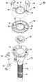
도 1은 본 발명의 실시예에 의한 분해 상태를 나타낸 정면도.
도 2는 본 발명의 실시예에 의한 투관침의 분해 상태를 나타낸 사시도.
도 3은 본 발명의 실시예에 의한 투관침의 결합 상태를 나타낸 정면도.
도 4는 본 발명의 실시예에 의한 투관침의 결합 상태를 나타낸 측면도.
도 5는 본 발명의 실시예에 의한 커넥터부재의 분해 상태를 나타낸 사시도.
도 6은 본 발명의 실시예에 의한 작동부재의 분해 상태를 나타낸 사시도.
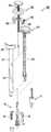
도 7은 본 발명의 실시예에 의한 봉합바늘부재의 분해 상태를 나타낸 사시도.
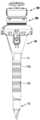
도 8은 본 발명의 실시예에 의한 투관팁의 결합 상태를 나타낸 사용상태도.
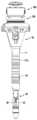
도 9는 본 발명의 실시예에 의한 봉합사카트리지의 결합 상태를 나타낸 사용상태도.
도 10 내지 도 12는 본 발명의 실시예에 의한 바늘부재의 작동 상태를 나타낸 작동도.1 is a front view showing an exploded state according to an embodiment of the present invention.
Figure 2 is a perspective view showing an exploded state of the trocar according to an embodiment of the present invention.
Figure 3 is a front view showing a coupling state of the trocar according to an embodiment of the present invention.
Figure 4 is a side view showing a coupling state of the trocar according to an embodiment of the present invention.
5 is a perspective view showing an exploded state of the connector member according to the embodiment of the present invention.
Figure 6 is a perspective view showing an exploded state of the operating member according to an embodiment of the present invention.
7 is a perspective view showing an exploded state of the suture needle member according to an embodiment of the present invention.
8 is a use state showing the coupling state of the bushing tip according to an embodiment of the present invention.
9 is a use state diagram showing a bonding state of the suture cartridge according to an embodiment of the present invention.
10 to 12 is an operation diagram showing an operating state of the needle member according to an embodiment of the present invention.
이하에서는 본 발명을 충분히 이해하기 위해서 본 발명의 바람직한 실시예를 첨부 도면을 참조하여 설명한다.DETAILED DESCRIPTION Hereinafter, preferred embodiments of the present invention will be described with reference to the accompanying drawings in order to fully understand the present invention.
본 발명의 실시예는 여러 가지 형태로 변형될 수 있으며, 본 발명의 범위가 아래에서 상세히 설명하는 실시예로 한정되는 것으로 해석되어서는 안 된다. 본 실시예는 당업계에서 평균적인 지식을 가진 자에게 본 발명을 더욱 완전하게 설명하기 위하여 제공되는 것이다.Embodiment of the present invention may be modified in various forms, the scope of the invention should not be construed as limited to the embodiments described in detail below. This embodiment is provided to more completely explain the present invention to those skilled in the art.
따라서, 도면에서 표현한 구성요소의 형상 등은 더욱 명확한 설명을 강조하기 위해서 과장되어 표현될 수 있다. 각 도면에서 동일한 구성은 동일한 참조부호로 도시한 경우가 있음을 유의하여야 한다. 또한, 본 발명의 요지를 불필요하게 흐릴 수 있다고 판단되는 공지 기술의 기능 및 구성에 관한 상세한 설명은 생략한다.Therefore, the shape of the components, etc. represented in the drawings may be exaggerated to emphasize a more clear description. It should be noted that the same configuration in each drawing is shown with the same reference numerals. In addition, the detailed description about the function and structure of the well-known technique which determine that the summary of this invention may be unnecessarily obscured is abbreviate | omitted.
본 발명은 도 1에 도시된 바와 같이, 수술용 절개창을 관통하는 캐뉼라(111) 및 양측에 바늘삽입공(112)이 구비된 투관침(100), 캐뉼라(111)로 안내되어 복강 내로 투관되는 투관팁(10) 및 상기 투관팁(10)에 의해 형성된 투관 구멍을 봉합하도록 상기 캐뉼라(111)로 안내되어 봉합사(1)를 양측으로 제공하는 봉합사카트리지(20) 중 어느 하나를 분리가능하게 장착하여 작동시키는 작동부재(300), 양측의 바늘삽입공(112)으로 각각 삽입되어 봉합사카트리지(20)에서 제공된 봉합사(1)를 절개창의 외부로 인출하는 봉합바늘부재(400)를 포함한다.As shown in FIG. 1, the
투관침(100)은 수술용 절개창을 지나 복막을 관통하여 의료용 카메라 또는 각종 수술도구를 복강 내로 안내하는 것으로서, 이러한 투관침(100)은 도 2에 도시된 바와 같이, 캐뉼라(111)를 갖는 투관침바디(110)와 투관침개스킷(120)과 투관침데코(130) 및 투관침커버(140)로 대별된다.The
투관침바디(110)는 투관침(100)의 골조를 이루는 것으로서, 이러한 투관침바디(110)는 내부가 빈 원통형의 캐뉼라(cannula, 111)가 일체로 구비되어 수술용 절개창을 지나 복막을 관통하고, 그 내부로 작동부재(300)나 의료용 카메라 또는 수술도구 등이 삽입되어 복강 내로 안내하게 된다. 도 2 및 도 3을 참조하면, 캐뉼라(111)의 외주연에는 외면이 하향으로 테이퍼(taper)지게 형성된 결합링(111a)이 축방향을 따라 연속적으로 형성되고 캐뉼라(111)의 저면은 어느 한 방향으로 경사진 사면(111b)으로 형성되어, 절개창 및 복막의 관통을 용이하게 할 수 있다. 캐뉼라(111)의 개방된 상단부에는 투관침개스킷(120)이 결합되어 작동부재(300)나 의료용 카메라 또는 수술도구의 삽입 시 기밀 상태를 유지하게 된다.The
투관침바디(110)의 좌우 양측에는 바늘삽입공(112)이 구비되어 봉합바늘부재(400)의 삽입을 안내하는데, 이러한 바늘삽입공(112)은 도 2에 도시된 바와 같이, 투관침바디(110)의 상면 좌우 양측에서 캐뉼라(111)의 하부 반대 방향으로 연이어져 통하도록 사선으로 형성된다. 이때, 양측의 바늘삽입공(112)은 봉합바늘부재(400)의 삽입 시 간섭되지 않도록 적절한 위치에 경사진 직선형으로 형성되며, 바늘삽입공(112)의 내경은 후술하는 봉합바늘부재(400)의 바늘이 전후 또는 좌우 방향으로 유동하지 않게 안내되도록 적절한 크기로 형성된다.Left and right sides of the
투관침바디(110)의 상부 일측에는 가스공급관(113)이 연결되어 의료용 가스를 주입하고, 가스공급관(113)의 상부에는 가스밸브(114)가 회전가능하게 설치되어 가스의 주입을 단속한다.The
투관침데코(130)는 투관침바디(110)의 상부에 결합되어 투관침개스킷(120)을 고정하게 된다. 투관침데코(130)는 캐뉼라(111)와 연이어져 통하도록 중앙에 데코통공(131)이 형성된 대략 원판형상으로 형성되어 투관침바디(110)의 개방된 상부를 차폐하고, 투관침데코(130)의 좌우 양측에는 투관침바디(110)의 바늘삽입공(112)에 연이어져 통하도록 바늘관통공(132)이 형성되며, 이 바늘관통공(132)의 상단에 인접된 둘레에는 홀캡보스(133)가 형성되어 후술하는 홀캡(143)이 끼움결합된다.The
투관침커버(140)는 투관침데코(130)의 상부에 결합되어 투관침데코(130)의 상부를 미려하게 마감한다. 투관침커버(140)는 투관침데코(130)의 데코통공(131)에 연이어져 통하도록 중앙에 커버통공(141)이 형성되고 상면이 완만히 만곡된 대략 고리형상으로 형성된다. 투관침커버(140)의 좌우 양측에는 보스결합공(142)이 형성되어 홀캡보스(133)의 상단부를 마감하도록 결합되며, 이 보스결합공(142)을 지나서 홀캡보스(133)에 홀캡(143)이 분리가능하게 결합되어 바늘관통공(132)을 개방하거나 폐쇄하게 된다. 그리고 투관침커버(140)의 커버통공(141) 내경에는 암나사(144)가 형성되어 후술하는 커넥터(200)의 수나사(221)가 나사결합된다.The
여기서, 커넥터(200)는 투관침(100)의 상부에 분리가능하게 결합되어 작동부재(300)를 용이하게 연결시킨다. 도 5를 참조하면, 커넥터(200)는 어퍼바디(210)와 로워바디(220)로 대별되고, 그 사이에 결합되는 암플레이트(230)와 수플레이트(240), 커넥터개스킷(250) 및 가이드플레이트(260)를 포함한다.Here, the
어퍼바디(210)와 로워바디(220)는 훅(hook) 결합되고 그 중앙에는 커넥터통공(200a)이 형성되어 후술하는 작동부재(300)의 슬리브의 관통을 안내한다. 어퍼바디(210)의 상면 좌우 양측에는 암훅(211)이 형성되어 후술하는 작동부재(300)의 수훅(350)이 훅 결합된다. 어퍼바디(210)의 상면 전후 양측에는 위치설정요부(212)가 형성되어 후술하는 작동부재(300)의 위치설정철부(313)에 요철결합된다. 로워바디(220)의 하부 외주연에는 수나사(221)가 형성되어 투관침커버(140)의 암나사(144)에 나사결합된다.The
커넥터개스킷(250)은 후술하는 작동부재(300)의 슬리브의 삽입 시 기밀 상태를 유지하는 것으로서, 그 상부와 하부는 암플레이트(230)와 수플레이트(240) 및 가이드플레이트(260)에 의해 고정된다.
작동부재(300)는 투관팁(10)과 봉합사카트리지(20) 중 어느 하나를 선택적으로 장착하여 작동시킨다. 도 6을 참조하면, 작동부재(300)는 투관팁(10)과 봉합사카트리지(20) 중 어느 하나를 선택적으로 장착하여 투관침(100) 및 커넥터(200)를 관통하도록 슬리브(311)를 갖는 작동바디(310), 슬리브(311)를 따라 안내되어 투관팁(10) 또는 봉합사카트리지(20)를 작동시키는 작동로드(320), 작동바디(310)의 상부를 마감하는 바디커버(330), 작동바디(310)의 양측에 구비되어 커넥터(200)의 암훅(211)에 훅 결합되도록 수훅(350)을 갖는 탈착버튼(340)을 포함한다.The operating
여기서, 본 발명의 작동부재(300)와 투관팁(10) 및 봉합사카트리지(20)에 대한 구성 및 작용은 본 출원인이 선출원한 등록특허 제1712611호(등록일자 2017.02.27) ‘복강경 포트 사이트 개폐 장치’의 공지된 내용으로 갈음할 수 있으므로 상세한 설명은 생략한다. 다만, 본 발명의 작동부재(300)와 투관팁(10) 및 봉합사카트리지(20)의 새로운 구성과 이를 통한 새로운 작용 및 효과를 갖는 부분은 이하에서 상세히 설명한다.Here, the configuration and operation of the
작동바디(310)는 작동부재(300)의 골조를 이루는 것으로서, 이러한 작동바디(310)의 하부에는 원통형의 슬리브(311)가 일체로 형성되어 커넥터(200)와 투관침(100)을 순차적으로 관통하고, 이 슬리브(311)의 하단부에는 투관팁(10) 또는 봉합사카트리지(20)가 탈착된다. 그리고 슬리브(311)의 외주연 좌우 양측에는 사선 방향으로 바늘안내홈(312)이 형성되어 봉합바늘부재(400)의 간섭 및 유동을 방지하게 된다. 또한, 작동바디(310)에는 위치설정철부(313)가 구비되어 상술한 커넥터(200)의 위치설정요부(212)에 요철결합되므로, 작동부재(300)와 커넥터(200)의 체결 시 정확한 위치를 설정할 수 있다.The operating
투관팁(10)은 슬리브(311)의 하단부에 탈착되는데, 이러한 투관팁(10)은 첨예한 단부를 가져서 캐뉼라(111)로 안내된 후 복강 내로 투관된다.The
봉합사카트리지(20)는 슬리브(311)의 하단부에 탈착되어 좌우 양측으로 봉합사(1)를 제공하게 된다. 도 6을 참조하면, 봉합사카트리지(20)의 하부 중앙에는 봉합사(1)를 넣은 북(21)이 구비되어 좌우 양측으로 봉합사(1)의 양측 단부를 인출하고, 봉합사카트리지(20)의 좌우 양측에는 가이드윙(22)이 외측으로 회전가능하게 연결되어 북(21)에서 인출된 봉합사(1)의 양단부를 걸어서 양측에 제공하도록 안내한다. 그리고 봉합사카트리지(20)의 가이드윙(21)은 작동로드(320)의 작동에 의해 외측으로 회전되도록 연결된다.The
봉합바늘부재(400)는 바늘삽입공(112)으로 삽입되어 봉합사카트리지(20)에서 제공된 봉합사(1)를 절개창의 외부로 인출한다. 도 7을 참조하면, 봉합바늘부재(400)는 바늘바디(410), 바늘바디(410)를 따라 슬라이딩 작동되어 봉합사카트리지(20)에서 제공되는 봉합사(1)를 견인하도록 미늘(451)을 갖는 봉합바늘(450), 봉합바늘(450)을 작동시키도록 바늘바디(410)에 결합되는 바늘핸들(420), 봉합바늘(450)의 작동을 탄성적으로 복원시키도록 바늘바디(410)에 설치되는 복원부재(460)를 포함한다.The
바늘바디(410)는 내부가 빈 원통형으로 형성되어, 상단부 내경에는 바늘핸들(420)이 슬라이딩 가능하게 연결되고 하단부는 바디캡(430)에 의해 마감되며, 바디캡(430)에는 길게 형성된 바늘보호관(440)이 결합되어 봉합바늘(450)의 슬라이딩 작동 및 미늘(451)을 보호하게 된다.The
봉합바늘(450)은 바늘바디(410)의 축방향을 따라 슬라이딩되어 봉합사카트리지(20)에서 제공되는 봉합사(1)를 견인하는데, 이를 위해 봉합바늘(450)의 단부에는 갈고리 형상의 미늘(451)이 형성되어 봉합사카트리지(20)에서 제공되는 봉합사(1)를 견인하게 된다. 봉합바늘(450)은 바늘보호관(440)을 따라 슬라이딩되어, 작동에 대한 안정성이 향상되고 미늘(451)이 외부로 노출되지 않도록 보호된다. 봉합바늘(450)의 상단부에는 바늘홀더(452)가 구비되어 바늘핸들(420)의 하단부에 연결된다.The
복원부재(460)는 바늘보호관(440)의 단부로 인출된 봉합바늘(450)을 탄성적으로 복원시키는 것으로서, 이러한 복원부재(460)는 도 7에 도시된 바와 같이, 바늘핸들(420)과 봉합바늘(450) 사이에 개재되는 코일스프링으로 구현되는 것이 바람직하다. 선택적으로, 복원부재(460)는 바늘보호관(440)의 단부로 인출된 봉합바늘(450)을 탄성적으로 복원시키도록 바늘핸들(420)과 봉합바늘(450) 사이에 개재되는 판스프링 따위로 구현될 수 있다.
이와 같이 구성된 본 발명의 전체적인 작용 및 효과를 첨부된 도면을 참조하여 상세히 설명한다.The overall operation and effects of the present invention configured as described above will be described in detail with reference to the accompanying drawings.
우선, 복강경 수술을 위하여 투관 구멍을 천공하는 작용을 살펴보면 다음과 같다.First, look at the effect of puncturing the trocar hole for laparoscopic surgery.
먼저, 수술용 절개창으로 투관침(100)의 캐뉼라(111)를 관통한 후, 작동부재(300)의 슬리브(311) 하단부에 투관팁(10)을 장착한다.First, after penetrating the
이어서, 작동부재(300)의 슬리브(311)를 투관침(100)의 캐뉼라(111)로 삽입하면, 투관팁(10)의 첨예한 단부에 의해 복강 내로 관통되어 투관 구멍을 형성하게 된다.Subsequently, when the
그리고 작동부재(300)를 투관침(100)에서 인출하는데, 이때 가스공급관(113)을 통해 의료용 가스를 주입할 수 있다.And withdraw the operating
다음으로, 투관팁(100)으로 천공된 투관 구멍을 봉합하는 작용을 살펴보면 다음과 같다.Next, look at the action to seal the bushing hole punched with the
먼저, 투관침(100)의 커버통공(141)에 형성된 암나사(144)에 커넥터(200)의 수나사(221)를 나사결합하면, 투관침(100)의 상부에 커넥터(200)가 결합한다.First, when the
이어서, 작동부재(300)의 슬리브(311) 하단부에 봉합사카트리지(20)를 장착한 후, 이 봉합사카트리지(20)가 장착된 작동부재(300)의 슬리브(311)를 커넥터(200)를 관통하여 투관침(100)의 캐뉼라(111)로 삽입한다. 이때, 커넥터(200)의 암훅(211)에 작동부재(300)의 수훅(350)을 훅 결합하여 견고한 결합력을 유지할 수 있다.Subsequently, the
그리고 작동부재(300)의 작동로드(320)를 상승시키면 양측의 가이드윙(22)이 외측 방향으로 회전되어 봉합사(1)를 좌우 양측으로 제공한다.Then, when the operating
계속해서, 봉합바늘부재(400)의 바늘보호관(440)을 좌측의 바늘관통공(132)으로 넣어서 바늘삽입공(112)으로 삽입하면, 바늘보호관(440)의 단부는 도 10에 도시된 바와 같이 캐뉼라(111)의 하부 우측 방향을 관통하게 된다. 이때, 바늘보호관(440)의 단부가 가이드윙(22)에 인접되도록 삽입한다.Subsequently, when the
이후, 바늘핸들(420)을 눌러 봉합바늘(450)이 바늘보호관(440)의 단부로 인출되면, 봉합바늘(450)의 미늘(451)이 가이드윙(22)에 걸린 봉합사(1)를 견인하여 좌측의 바늘삽입공(112)과 바늘관통공(132)을 지나 절개창의 외부로 인출한 후, 홀딩시킨다.Thereafter, when the
이어서, 봉합바늘부재(400)의 바늘보호관(440)을 우측의 바늘관통공(132)으로 넣어서 바늘삽입공(112)으로 삽입하면, 바늘보호관(440)의 단부는 도 11에 도시된 바와 같이 캐뉼라(111)의 하부 좌측 방향을 관통하게 된다. 이때, 바늘보호관(440)의 단부가 가이드윙(22)에 인접되도록 삽입한다.Subsequently, when the
그 다음, 바늘핸들(420)을 눌러 봉합바늘(450)이 바늘보호관(440)의 단부로 인출되면, 봉합바늘(450)의 미늘(451)이 가이드윙(22)에 걸린 봉합사(1)를 견인하여 우측의 바늘삽입공(112)과 바늘관통공(132)을 지나 절개창의 외부로 인출한 후, 홀딩시킨다.Next, when the
도 12에 도시된 바와 같이, 절개창의 외부로 인출된 봉합사(1)의 양단부를 묶어서 매듭을 지으면, 복강경 수술을 위해 투관팁(10)으로 천공된 투관 구멍의 봉합이 마무리된다.As shown in FIG. 12, when both ends of the
이상에서 설명된 본 발명의 실시예는 예시적인 것에 불과하며, 본 발명이 속한 기술분야의 통상의 지식을 가진 자라면 이로부터 다양한 변형 및 균등한 타 실시예가 가능하다는 점을 잘 알 수 있을 것이다.Embodiments of the present invention described above are merely exemplary, and those skilled in the art will appreciate that various modifications and equivalent other embodiments are possible therefrom.
그러므로 본 발명은 상기의 상세한 설명에서 언급되는 형태로만 한정되는 것은 아님을 잘 이해할 수 있을 것이다.Therefore, it will be understood that the present invention is not limited to the forms mentioned in the above detailed description.
따라서 본 발명의 진정한 기술적 보호 범위는 첨부된 특허청구범위의 기술적 사상에 의해 정해져야 할 것이다. 또한, 본 발명은 첨부된 청구범위에 의해 정의되는 본 발명의 정신과 그 범위 내에 있는 모든 변형물과 균등물 및 대체물을 포함하는 것으로 이해되어야 한다.Therefore, the true technical protection scope of the present invention will be defined by the technical spirit of the appended claims. It is also to be understood that the present invention includes all modifications, equivalents, and substitutes within the spirit and scope of the invention as defined by the appended claims.
10 : 투관팁20 : 봉합사카트리지
22 : 가이드윙100 : 투관침
110 : 투관침바디111 : 캐뉼라
112 : 바늘삽입공120 : 투관침개스킷
130 : 투관침데코140 : 투관침커버
200 : 커넥터211 : 암훅
250 : 커넥터개스킷300 : 작동부재
310 : 작동바디311 : 슬리브
320 : 작동로드340 : 탈착버튼
350 : 수훅400 : 봉합바늘부재
410 : 바늘바디420 : 바늘핸들
440 : 바늘보호관450 : 봉합바늘10: bushing tip 20: suture cartridge
22: guide wing 100: trocar
110: trocar body 111: cannula
112: needle insertion hole 120: bushing acupuncture gasket
130: trocar deco 140: trocar cover
200
250: connector gasket 300: operating member
310: working body 311: sleeve
320: operation rod 340: release button
350: hook 400: sewing needle member
410: needle body 420: needle handle
440: needle protection tube 450: sewing needle
Claims (7)
Translated fromKorean상기 양측의 바늘삽입공은 투관침의 상부 양측에서 캐뉼라의 하부 반대 방향으로 경사진 선형으로 형성되고,
상기 투관침은, 상기 양측 바늘삽입공 및 캐뉼라가 구비된 투관침바디, 상기 투관침바디의 상부에 결합되어 상기 바늘삽입공에 연이어져 통하도록 바늘관통공이 형성된 투관침데코, 상기 투관침데코의 상부를 마감하도록 결합되는 투관침커버를 포함하며,
상기 투관침데코에는 바늘관통공의 상단 둘레에 홀캡보스가 형성되고, 상기 홀캡보스에는 상기 바늘관통공을 개폐하도록 홀캡이 결합되는 것을 특징으로 하는 봉합기능을 갖는 복강경 수술용 투관침.A cannula penetrating through the surgical incision and a trocar having a needle insertion hole at both sides, a cantilever tip guided into the cannula and a cantilever hole formed by the cannula tip, and guided by the cannula to suture the cannula to provide a suture to both sides. An operating member for selectively detachably mounting any one of the suture cartridge to be operated, including a suture needle member which is inserted into each of the needle insertion holes on both sides to draw the suture provided in the suture cartridge to the outside of the incision,
The needle insertion holes on both sides are linearly inclined in the opposite direction of the lower part of the cannula on both sides of the upper trocar,
The trocar needle, the trocar body provided with the needle insertion hole and the cannula on both sides, the trocar deco coupled to the upper portion of the trocar needle body through the needle insertion hole is formed so as to pass through the needle insertion hole, coupled to close the top of the trocar deco Includes a trocar cover,
The trocar deco is a hole cap boss is formed around the upper end of the needle through hole, the hole cap boss is a laparoscopic surgical trocar with a suture function, characterized in that the hole cap is coupled to open and close the needle through hole.
상기 작동부재에는 상기 바늘삽입공으로 삽입되는 양측 봉합바늘부재의 간섭을 방지하도록 안내하는 바늘안내홈이 형성된 것을 특징으로 하는 봉합기능을 갖는 복강경 수술용 투관침.The method according to claim 1,
Laparoscopic surgical trocar with a suture function is formed in the operating member is formed with a needle guide groove for guiding to prevent the interference of the two side sewing needle member inserted into the needle insertion hole.
상기 투관침의 상부에 분리가능하게 결합되는 커넥터를 더 포함하되,
상기 커넥터에는 수나사가 형성되어 상기 투관침의 상부에 형성된 암나사에 분리가능하게 나사결합되는 것을 특징으로 하는 봉합기능을 갖는 복강경 수술용 투관침.The method according to claim 1,
Further comprising a connector detachably coupled to the upper portion of the trocar,
The connector is a laparoscopic surgical trocar having a suture function characterized in that the male screw is formed detachably screwed to the female screw formed on the upper portion of the trocar.
상기 작동부재는, 상기 투관팁과 봉합사카트리지 중 어느 하나를 선택적으로 장착하여 투관침 및 커넥터를 관통하도록 슬리브를 갖는 작동바디, 상기 슬리브를 따라 안내되어 상기 투관팁 또는 봉합사카트리지를 작동시키는 작동로드, 상기 작동바디의 상부를 마감하는 바디커버, 상기 작동바디의 양측에 구비되어 상기 커넥터에 분리가능하게 결합되는 탈착버튼을 포함하되,
상기 슬리브에는 상기 바늘삽입공으로 삽입되는 양측 봉합바늘부재의 간섭을 방지하도록 안내하는 바늘안내홈이 형성된 것을 특징으로 하는 봉합기능을 갖는 복강경 수술용 투관침.The method according to claim 4,
The actuating member may include: an operating body having a sleeve for selectively mounting any one of the bushing tip and the suture cartridge to penetrate the trocar and the connector; an actuating rod guided along the sleeve to operate the bushing tip or the suture cartridge; Body cover for closing the top of the operating body, including a detachable button provided on both sides of the operating body detachably coupled to the connector,
Laparoscopic trocar with a suture function characterized in that the sleeve is formed with a needle guide groove for guiding to prevent interference of the two side sewing needle member inserted into the needle insertion hole.
상기 봉합바늘부재는, 바늘바디, 상기 바늘바디를 따라 슬라이딩 작동되어 상기 봉합사카트리지에서 제공되는 봉합사를 견인하도록 미늘을 갖는 봉합바늘, 상기 봉합바늘을 작동시키도록 상기 바늘바디에 결합되는 바늘핸들, 상기 봉합바늘의 작동을 탄성적으로 복원시키도록 바늘바디에 설치되는 복원부재를 포함하는 봉합기능을 갖는 복강경 수술용 투관침.The method according to claim 1,
The suture needle member is a needle body, a needle operated to slide along the needle body to pull the suture provided in the suture cartridge, a needle having a barb, a needle handle coupled to the needle body to operate the suture needle, the A laparoscopic surgical trocar having a suture function comprising a restoring member installed on the needle body to elastically restore the operation of the suture needle.
상기 바늘바디에는 상기 봉합바늘의 슬라이딩 작동 및 상기 미늘을 보호하도록 바늘보호관이 연결된 것을 특징으로 하는 봉합기능을 갖는 복강경 수술용 투관침.The method according to claim 6,
The needle body is a laparoscopic surgical trocar with a suture function, characterized in that the needle protection tube is connected to protect the barb and the sliding operation of the suture needle.
Priority Applications (1)
| Application Number | Priority Date | Filing Date | Title |
|---|---|---|---|
| KR1020170102164AKR102026748B1 (en) | 2017-08-11 | 2017-08-11 | Trocar for laparoscopic surgery |
Applications Claiming Priority (1)
| Application Number | Priority Date | Filing Date | Title |
|---|---|---|---|
| KR1020170102164AKR102026748B1 (en) | 2017-08-11 | 2017-08-11 | Trocar for laparoscopic surgery |
Publications (2)
| Publication Number | Publication Date |
|---|---|
| KR20190017382A KR20190017382A (en) | 2019-02-20 |
| KR102026748B1true KR102026748B1 (en) | 2019-09-30 |
Family
ID=65562000
Family Applications (1)
| Application Number | Title | Priority Date | Filing Date |
|---|---|---|---|
| KR1020170102164AActiveKR102026748B1 (en) | 2017-08-11 | 2017-08-11 | Trocar for laparoscopic surgery |
Country Status (1)
| Country | Link |
|---|---|
| KR (1) | KR102026748B1 (en) |
Cited By (2)
| Publication number | Priority date | Publication date | Assignee | Title |
|---|---|---|---|---|
| KR20250025868A (en) | 2023-08-16 | 2025-02-25 | 한림대학교 산학협력단 | Surgical device including plasmonic needle |
| KR20250035324A (en) | 2023-09-05 | 2025-03-12 | 한림대학교 산학협력단 | Surgical device that performs motion sensing using optical fiber |
Families Citing this family (5)
| Publication number | Priority date | Publication date | Assignee | Title |
|---|---|---|---|---|
| CN112674844A (en)* | 2019-10-20 | 2021-04-20 | 钟焕龙 | Integrated laparoscope puncture stitching instrument under direct vision |
| KR102274131B1 (en)* | 2019-11-12 | 2021-07-06 | 김기성 | Trocar system for laparoscopic surgery |
| KR102278476B1 (en)* | 2019-11-12 | 2021-07-15 | 김기성 | Trocar system for laparoscopic surgery |
| CN112790838B (en)* | 2021-02-26 | 2024-10-15 | 复旦大学附属中山医院 | Reverse puncture system capable of being positioned accurately |
| KR102622182B1 (en)* | 2021-07-07 | 2024-01-08 | (주)헤페스토스 | A Medical Tool Having a Function of Guiding for Getting a Stitch |
Citations (4)
| Publication number | Priority date | Publication date | Assignee | Title |
|---|---|---|---|---|
| US20080097485A1 (en) | 2005-04-19 | 2008-04-24 | Vladimir Shpaichler | Device for wound suturing and hemostasis in the thoracic and the abdominal wall mainly in endoscopic operations |
| WO2009155287A1 (en)* | 2008-06-17 | 2009-12-23 | Apollo Endosurgery, Inc. | Endoscopic suturing system |
| KR101019222B1 (en) | 2010-04-14 | 2011-03-04 | 정경진 | Laparoscopic Trocar Assembly |
| KR101712611B1 (en)* | 2016-08-05 | 2017-03-06 | 김기성 | Laparoscopic port site opening and closing apparatus |
Family Cites Families (1)
| Publication number | Priority date | Publication date | Assignee | Title |
|---|---|---|---|---|
| KR200473904Y1 (en)* | 2013-12-02 | 2014-08-08 | 가톨릭대학교 산학협력단 | Trocar for laparoscopic surgery |
- 2017
- 2017-08-11KRKR1020170102164Apatent/KR102026748B1/enactiveActive
Patent Citations (4)
| Publication number | Priority date | Publication date | Assignee | Title |
|---|---|---|---|---|
| US20080097485A1 (en) | 2005-04-19 | 2008-04-24 | Vladimir Shpaichler | Device for wound suturing and hemostasis in the thoracic and the abdominal wall mainly in endoscopic operations |
| WO2009155287A1 (en)* | 2008-06-17 | 2009-12-23 | Apollo Endosurgery, Inc. | Endoscopic suturing system |
| KR101019222B1 (en) | 2010-04-14 | 2011-03-04 | 정경진 | Laparoscopic Trocar Assembly |
| KR101712611B1 (en)* | 2016-08-05 | 2017-03-06 | 김기성 | Laparoscopic port site opening and closing apparatus |
Cited By (2)
| Publication number | Priority date | Publication date | Assignee | Title |
|---|---|---|---|---|
| KR20250025868A (en) | 2023-08-16 | 2025-02-25 | 한림대학교 산학협력단 | Surgical device including plasmonic needle |
| KR20250035324A (en) | 2023-09-05 | 2025-03-12 | 한림대학교 산학협력단 | Surgical device that performs motion sensing using optical fiber |
Also Published As
| Publication number | Publication date |
|---|---|
| KR20190017382A (en) | 2019-02-20 |
Similar Documents
| Publication | Publication Date | Title |
|---|---|---|
| KR102026748B1 (en) | Trocar for laparoscopic surgery | |
| CN105848590B (en) | Laparoscope puncture orifice position closing device | |
| US5613975A (en) | Endoscopic suturing device and method | |
| EP0691859B1 (en) | Trocar and cannula | |
| KR101712611B1 (en) | Laparoscopic port site opening and closing apparatus | |
| US5284474A (en) | Trochar system for laparoscopy | |
| ATE389356T1 (en) | SUBCUTANEOUS SEWING DEVICE FOR CLOSING AN OPENING IN THE ABDOMINAL WALL OF A PATIENT | |
| JPH09501855A (en) | Laparoscopic safety device | |
| KR102278476B1 (en) | Trocar system for laparoscopic surgery | |
| KR200473904Y1 (en) | Trocar for laparoscopic surgery | |
| CN108261227A (en) | It is a kind of to puncture core assembly and with its puncture outfit | |
| TW201601676A (en) | Suturing and knotting integrated device for laparoscopic surgery and knotting assembly for associated surgery | |
| CN113081191B (en) | A puncture suture device | |
| CN208573778U (en) | Knotting device in a kind of laparoscope puncture incision | |
| CN211934140U (en) | Interventional defect stitching instrument | |
| KR101859208B1 (en) | For laparoscopic trocar port intermediate connector structure | |
| CN108261228A (en) | A kind of puncture outfit | |
| CN110613491B (en) | Puncture needle with thread | |
| CN211609986U (en) | Integrated laparoscope puncture stitching instrument under direct vision | |
| CN108938022A (en) | For suturing the stitching unstrument of hysteroscope puncture | |
| KR102274131B1 (en) | Trocar system for laparoscopic surgery | |
| KR200225609Y1 (en) | Trocar | |
| CN209253051U (en) | A kind of visual puncturing device | |
| JP3725795B2 (en) | Trocar mantle | |
| CN112674844A (en) | Integrated laparoscope puncture stitching instrument under direct vision |
Legal Events
| Date | Code | Title | Description |
|---|---|---|---|
| A201 | Request for examination | ||
| PA0109 | Patent application | St.27 status event code:A-0-1-A10-A12-nap-PA0109 | |
| PA0201 | Request for examination | St.27 status event code:A-1-2-D10-D11-exm-PA0201 | |
| D13-X000 | Search requested | St.27 status event code:A-1-2-D10-D13-srh-X000 | |
| D14-X000 | Search report completed | St.27 status event code:A-1-2-D10-D14-srh-X000 | |
| R17-X000 | Change to representative recorded | St.27 status event code:A-3-3-R10-R17-oth-X000 | |
| E902 | Notification of reason for refusal | ||
| PE0902 | Notice of grounds for rejection | St.27 status event code:A-1-2-D10-D21-exm-PE0902 | |
| PG1501 | Laying open of application | St.27 status event code:A-1-1-Q10-Q12-nap-PG1501 | |
| E13-X000 | Pre-grant limitation requested | St.27 status event code:A-2-3-E10-E13-lim-X000 | |
| P11-X000 | Amendment of application requested | St.27 status event code:A-2-2-P10-P11-nap-X000 | |
| P13-X000 | Application amended | St.27 status event code:A-2-2-P10-P13-nap-X000 | |
| E701 | Decision to grant or registration of patent right | ||
| PE0701 | Decision of registration | St.27 status event code:A-1-2-D10-D22-exm-PE0701 | |
| GRNT | Written decision to grant | ||
| PR0701 | Registration of establishment | St.27 status event code:A-2-4-F10-F11-exm-PR0701 | |
| PR1002 | Payment of registration fee | St.27 status event code:A-2-2-U10-U11-oth-PR1002 Fee payment year number:1 | |
| PG1601 | Publication of registration | St.27 status event code:A-4-4-Q10-Q13-nap-PG1601 | |
| PR1001 | Payment of annual fee | St.27 status event code:A-4-4-U10-U11-oth-PR1001 Fee payment year number:4 | |
| PR1001 | Payment of annual fee | St.27 status event code:A-4-4-U10-U11-oth-PR1001 Fee payment year number:5 | |
| PR1001 | Payment of annual fee | St.27 status event code:A-4-4-U10-U11-oth-PR1001 Fee payment year number:6 | |
| PR1001 | Payment of annual fee | St.27 status event code:A-4-4-U10-U11-oth-PR1001 Fee payment year number:7 |