KR102025287B1 - Control device and method for chare - Google Patents
Control device and method for chareDownload PDFInfo
- Publication number
- KR102025287B1 KR102025287B1KR1020150099049AKR20150099049AKR102025287B1KR 102025287 B1KR102025287 B1KR 102025287B1KR 1020150099049 AKR1020150099049 AKR 1020150099049AKR 20150099049 AKR20150099049 AKR 20150099049AKR 102025287 B1KR102025287 B1KR 102025287B1
- Authority
- KR
- South Korea
- Prior art keywords
- charging
- battery
- soc
- battery module
- battery modules
- Prior art date
- Legal status (The legal status is an assumption and is not a legal conclusion. Google has not performed a legal analysis and makes no representation as to the accuracy of the status listed.)
- Active
Links
Images


Classifications
- H—ELECTRICITY
- H02—GENERATION; CONVERSION OR DISTRIBUTION OF ELECTRIC POWER
- H02J—CIRCUIT ARRANGEMENTS OR SYSTEMS FOR SUPPLYING OR DISTRIBUTING ELECTRIC POWER; SYSTEMS FOR STORING ELECTRIC ENERGY
- H02J7/00—Circuit arrangements for charging or depolarising batteries or for supplying loads from batteries
- H02J7/0013—Circuit arrangements for charging or depolarising batteries or for supplying loads from batteries acting upon several batteries simultaneously or sequentially
- H02J7/0014—Circuits for equalisation of charge between batteries
- H02J7/0018—Circuits for equalisation of charge between batteries using separate charge circuits
- H02J7/0077—
- H02J2007/0037—
Landscapes
- Engineering & Computer Science (AREA)
- Power Engineering (AREA)
- Secondary Cells (AREA)
- Charge And Discharge Circuits For Batteries Or The Like (AREA)
Abstract
Translated fromKoreanDescription
Translated fromKorean본 발명은 충전 제어 장치 및 방법에 관한 것으로, 더욱 상세하게는 다수의 배터리 모듈이 직렬로 연결된 배터리팩을 충전할 수 있는 충전 제어 장치에 관한 것이다.The present invention relates to a charging control device and method, and more particularly to a charging control device capable of charging a battery pack connected in series with a plurality of battery modules.
최근 이차전지 분야의 기술 발달에 따라 복수 개의 배터리 모듈로 구성된 배터리팩이 개발되어 넓은 분야에 사용되고 있다. 이에 배터리팩을 사용함에 있어서 배터리팩을 구성하는 복수 개의 배터리 모듈 각각을 균등하게 충전할 수 기술의 개발이 요구 되고 있다.Recently, battery packs composed of a plurality of battery modules have been developed according to technological developments in the secondary battery field, and have been used in a wide range of fields. Accordingly, in using the battery pack, development of a technology capable of equally charging each of a plurality of battery modules constituting the battery pack is required.
한편, 배터리팩을 구성하는 복수 개의 배터리 모듈들을 균등하게 충전하기 위한 기술들 중 하나로서 배터리팩에서 최대 SOC(State Of Charge)를 유지하는 배터리 모듈과 최소 SOC를 유지하는 배터리 모듈간의 편차를 산출하고, 산출된 편차가 미리 설정된 일정 값 이하를 유지하도록 충전을 제어하는 기술이 사용되었다.Meanwhile, as one of techniques for equally charging a plurality of battery modules constituting the battery pack, a deviation between the battery module maintaining the maximum state of charge (SOC) and the battery module maintaining the minimum SOC is calculated. As a result, a technique is used to control the charging so that the calculated deviation remains below a predetermined constant value.
하지만 상기 방법에 의해 충전되는 배터리팩은 최대 SOC를 유지하는 배터리 모듈에 미리 설정된 에너지 량이 충전되면 BMS(Battery Management System)가 배터리의 과충전에 의한 배터리팩의 손상을 방지하기 위해 과충전 보호 동작을 수행하게되어 충전이 종료된다. 따라서 최대 SOC를 유지하는 배터리 모듈 이외의 나머지 배터리 모듈들은 적은 충전 시간에 의해 SOC 낮은 상태로 충전이 종료되는 어려움이 있다. 이는 배터리팩을 균등하게 충전 하는 기술과 배터리 보호 회로 간의 상호 관계를 고려하지 않기 때문이다.However, the battery pack charged by the above method causes the battery management system (BMS) to perform an overcharge protection operation to prevent damage to the battery pack due to overcharging of the battery when a predetermined amount of energy is charged in the battery module maintaining the maximum SOC. Charging is terminated. Therefore, the remaining battery modules other than the battery module that maintains the maximum SOC has a difficulty in terminating the charge to the SOC low state due to the low charging time. This is because it does not take into account the mutual relationship between the technology of charging the battery pack evenly and the battery protection circuit.
따라서, 배터리팩을 구성하는 복수 개의 배터리 모듈들의 충전 과정 중 배터리 보호 회로에 의해 충전이 중단되지 않는 배터리팩 충전 기술의 개발이 요구된다.Therefore, it is required to develop a battery pack charging technology in which charging is not interrupted by a battery protection circuit during a charging process of a plurality of battery modules constituting the battery pack.
또한, 배터리팩을 구성하는 복수 개의 배터리 모듈들을 충전함에 있어서, 최대 SOC를 유지하는 배터리팩의 충전이 완료되어도 나머지 배터리 모듈들의 충전을 위해 충전 동작이 종료되지 않는 수 있는 배터리팩 충전 기술의 개발이 요구된다.In addition, in charging a plurality of battery modules constituting the battery pack, even if the charging of the battery pack maintaining the maximum SOC is completed, the development of the battery pack charging technology that the charging operation is not terminated for the charge of the remaining battery modules Required.
본 발명은 배터리팩을 구성하는 복수 개의 배터리 모듈들의 충전 과정 중 배터리 보호 회로에 의해 충전이 중단되지 않는 충전 제어 장치 및 방법을 제공한다.The present invention provides a charging control device and method in which charging is not interrupted by a battery protection circuit during a charging process of a plurality of battery modules constituting a battery pack.
또한, 본 발명은 배터리팩을 구성하는 복수 개의 배터리 모듈들을 충전함에 있어서, 최대 SOC를 유지하는 배터리팩의 충전이 완료되어도 나머지 배터리 모듈들의 충전을 위해 충전 동작이 종료되지 않는 충전 제어 장치 및 방법을 제공한다.In addition, the present invention provides a charging control device and method for charging a plurality of battery modules constituting the battery pack, the charging operation is not terminated for charging the remaining battery modules even when the battery pack maintaining the maximum SOC is completed. to provide.
본 발명의 실시 예에 따른 충전 제어 장치는, 복수 개의 배터리 모듈들이 직렬로 연결된 배터리팩을 충전하는 충전 제어 장치에 있어서, 상기 복수 개의 배터리 모듈들을 구성하는 각각의 배터리 모듈의 전류, 전압 및 온도를 측정하는 AFE(Analog Front End)부; 상기 AFE부로부터 상기 전류, 전압 및 온도를 전달받아 상기 각각의 배터리 모듈의 SOC(State Of Charge)를 실시간 산출하고, 상기 복수 개의 배터리 모듈 중 최대 SOC를 갖는 배터리 모듈의 정전류 충전제한 전압까지 복수 개의 충전 전원들 중 특정 전압 값을 갖는 특정 충전 전원으로 상기 복수 개의 배터리 모듈들을 충전하고, 상기 최대 SOC를 갖는 배터리 모듈의 SOC가 상기 정전류 충전 제한 전압을 넘어서 충전되는 경우, 상기 최대 SOC를 갖는 배터리 모듈로 흐르는 충전 전류를 차단하며, 상기 최대 SOC를 갖는 배터리 모듈을 제외한 나머지 배터리 모듈 중 최대 SOC를 갖는 배터리 모듈의 정전류 충전 제한 전압까지 상기 복수 개의 충전 전원들 중 상기 특정 전압 값과 다른 전압 값을 갖는 다른 충전 전원으로 상기 나머지 배터리 모듈 중 최대 SOC를 갖는 배터리 모듈이 충전되도록 제어하는 제어부; 및 서로 다른 전압 값을 가진 상기 복수 개의 충전 전원을 출력하는 복수 개의 직류-직류 변환기들로 구성되는 충전 전원 공급부; 를 포함할 수 있다.A charging control device according to an embodiment of the present invention, in a charging control device for charging a battery pack in which a plurality of battery modules are connected in series, the current, voltage and temperature of each battery module constituting the plurality of battery modules An analog front end (AFE) unit for measuring; Receives the current, voltage and temperature from the AFE unit to calculate the state of charge (SOC) of each of the battery modules in real time, a plurality of up to the constant current charge limit voltage of the battery module having a maximum SOC of the plurality of battery modules The battery module having the maximum SOC when the plurality of battery modules are charged with a specific charging power having a specific voltage value among charging powers, and the SOC of the battery module having the maximum SOC is charged beyond the constant current charge limit voltage. A charging current flowing to the battery is blocked and has a voltage value different from the specific voltage value among the plurality of charging power sources up to the constant current charging limit voltage of the battery module having the maximum SOC, except for the battery module having the maximum SOC. Battery with maximum SOC among the remaining battery modules with different charging power A control unit for controlling the module to be charged; And a plurality of DC-DC converters configured to output the plurality of charging powers having different voltage values. It may include.
상기 제어부는, 상기 각각의 배터리 모듈의 SOC를 실시간 산출한 후, 상기 산출된 SOC를 크기가 큰 순서대로 정렬하고, 상기 복수 개의 배터리 모듈들 중 상기 정렬된 SOC 중 최대 SOC에 대응되는 배터리 모듈을 선택하며, 상기 선택된 배터리 모듈의 SOC를 고려하여 상기 충전 전원 공급부의 상기 복수 개의 충전 전원들 중 어느 하나를 선택하는 충전 전원 선택 신호를 생성하고, 상기 생성된 충전 전원 선택 신호를 상기 충전 전원 공급부로 전달할 수 있다.The control unit calculates the SOC of each of the battery modules in real time, and sorts the calculated SOCs in order of increasing magnitude, and selects a battery module corresponding to a maximum SOC among the aligned SOCs among the plurality of battery modules. And generate a charging power selection signal for selecting any one of the plurality of charging power sources of the charging power supply unit in consideration of the SOC of the selected battery module, and converting the generated charging power selection signal to the charging power supply unit. I can deliver it.
상기 제어부는, 상기 복수 개의 배터리 모듈들이 각각 정전류 충전 제한 전압까지 충전이 완료된 경우, 상기 복수 개의 배터리 모듈들의 충전이 완료되었음을 나타내는 충전 완료 신호를 생성하고, 상기 충전 전원 공급부를 통해 공급되는 충전 전원에 의해 상기 복수 개의 배터리 모듈들이 과충전되는 것을 방지하기 위해 생성된 상기 충전 완료 신호를 상기 배터리팩의 배터리 관리 시스템(Battery Management System)에 전송할 수 있다.The controller may generate a charging completion signal indicating that the charging of the plurality of battery modules is completed when charging of the plurality of battery modules to the constant current charging limit voltage is completed, and supplies the charging power supplied through the charging power supply unit. The charging completion signal generated to prevent the plurality of battery modules from being overcharged may be transmitted to a battery management system of the battery pack.
상기 충전 전원 공급부는, 상기 제어부로부터 상기 충전 전원 선택 신호를 전달받는 통신부를 더 포함하며, 수신된 상기 충전 전원 선택 신호에 따라 상기 복수 개의 직류-직류 변환기들 중 하나를 선택하여 충전 전원을 출력할 수 있다.The charging power supply unit may further include a communication unit configured to receive the charging power selection signal from the controller, and select one of the plurality of DC-DC converters according to the received charging power selection signal to output charging power. Can be.
상기 AFE부는, 상기 복수 개의 배터리 모듈들과 일대일로 대응되는 복수 개의 AFE들을 포함할 수 있다.The AFE unit may include a plurality of AFEs that correspond one-to-one with the plurality of battery modules.
상기 복수 개의 AFE들을 구성하는 각각의 AFE는 인접한 AFE 소자와 격리(Isolation) 소자를 통해 서로 연결될 수 있다.Each AFE constituting the plurality of AFEs may be connected to each other through an adjacent AFE element and an isolation element.
본 발명의 실시 예에 따른 충전 제어 방법은, 복수 개의 배터리 모듈들이 직렬로 연결된 배터리팩을 충전하는 충전 제어 방법에 있어서, 상기 복수 개의 배터리 모듈들을 구성하는 각각의 배터리 모듈의 전류, 전압 및 온도를 측정하여 상기 각각의 배터리 모듈의 SOC(State Of Charge)를 실시간 산출하는 제1 단계; 상기 복수 개의 배터리 모듈 중 최대 SOC를 갖는 배터리 모듈의 SOC의 정전압(Constant Voltage) 구간 직전까지 상기 복수 개의 배터리 모듈들을 복수 개의 충전 전원들 중 특정 전압 값을 갖는 특정 충전 전원으로 충전하는 제2 단계; 상기 최대 SOC를 갖는 배터리 모듈의 SOC가 상기 정전류 충전 제한 전압을 초과하여 충전되는 경우, 상기 최대 SOC를 갖는 배터리 모듈로 흐르는 충전 전류를 차단하는 제3 단계; 상기 최대 SOC를 갖는 배터리 모듈을 제외한 나머지 배터리 모듈 중 최대 SOC를 갖는 배터리 모듈의 정전류 충전 제한 전압까지 상기 최대 SOC를 갖는 배터리 모듈을 제외한 나머지 배터리 모듈 중 최대 SOC를 갖는 배터리 모듈을 상기 복수 개의 충전 전원들 중 상기 특정 전압 값과 다른 전압 값을 갖는 다른 충전 전원으로 충전하는 제4 단계; 및 상기 각각의 배터리 모듈이 정전류 충전 제한 전압까지 충전이 완료될 때까지 상기 제1 단계 내지 제4 단계를 반복 수행하는 제5 단계; 를 포함할 수 있다.In a charge control method according to an embodiment of the present invention, in a charge control method for charging a battery pack in which a plurality of battery modules are connected in series, the charge control method may include: Measuring and calculating a state of charge (SOC) of each battery module in real time; A second step of charging the plurality of battery modules with a specific charging power source having a specific voltage value among a plurality of charging power sources until immediately before a constant voltage section of the SOC of the battery module having the maximum SOC among the plurality of battery modules; A third step of blocking a charging current flowing to the battery module having the maximum SOC when the SOC of the battery module having the maximum SOC is charged beyond the constant current charging limit voltage; The plurality of charging power sources may include a battery module having the maximum SOC among the remaining battery modules except the battery module having the maximum SOC, up to a constant current charge limit voltage of the battery module having the maximum SOC, except for the battery module having the maximum SOC. A fourth step of charging with another charging power source having a voltage value different from the specific voltage value; And a fifth step of repeating the first to fourth steps until each of the battery modules is charged up to the constant current charge limit voltage. It may include.
상기 제1 단계는, 상기 산출된 SOC를 크기가 큰 순서대로 정렬하는 단계; 상기 복수 개의 배터리 모듈들 중 상기 정렬된 SOC 중 최대 SOC에 대응되는 배터리 모듈을 선택하는 단계; 상기 선택된 배터리 모듈의 SOC를 고려하여 상기 복수 개의 충전 전원들 중 어느 하나를 선택하는 충전 전원 선택 신호를 생성하는 단계; 및 상기 생성된 충전 전원 선택 신호를 구비된 충전 전원 공급부로 전달하여, 상기 충전 전원이 공급되도록 제어하는 단계; 를 더 포함할 수 있다.The first step includes: sorting the calculated SOCs in order of increasing magnitude; Selecting a battery module corresponding to a maximum SOC among the aligned SOCs among the plurality of battery modules; Generating a charging power selection signal for selecting any one of the plurality of charging power sources in consideration of the SOC of the selected battery module; And transmitting the generated charging power selection signal to a charging power supply provided to control the charging power to be supplied. It may further include.
상기 제5 단계 이후에, 상기 각각의 배터리 모듈이 정전류 충전 제한 전압까지 충전이 완료되었는지 판단하는 제6 단계; 상기 판단 결과, 상기 각각의 배터리 모듈이 정전류 충전 제한 전압까지 충전이 완료된 경우, 상기 복수 개의 배터리 모듈들의 충전이 완료되었음을 나타내는 충전 완료 신호를 생성하는 단계; 및 구비된 충전 전원 공급부를 통해 공급되는 충전 전원에 의해 상기 복수 개의 배터리 모듈들이 과충전되는 것을 방지하기 위해 생성된 상기 충전 완료 신호를 상기 배터리팩의 배터리 관리 시스템(Battery Management System)에 전송하는 단계; 를 더 포함할 수 있다.A sixth step after the fifth step, determining whether each of the battery modules has completed charging up to a constant current charge limit voltage; Generating a charge completion signal indicating that charging of the plurality of battery modules is completed when each of the battery modules is charged to a constant current charge limit voltage; And transmitting the charge completion signal generated to prevent the plurality of battery modules from being overcharged by the charging power supplied through the provided charging power supply to a battery management system of the battery pack. It may further include.
본 발명의 실시 예들에 따른 충전 제어 장치 및 방법은 배터리팩을 구성하는 복수 개의 배터리 모듈들의 충전 과정 중 배터리팩을 구성하는 모든 배터리 모듈의 SOC를 고려하여 충전을 진행함으로 충전 완료되기 이전에는 배터리 보호 회로에 의해 배터리팩의 충전이 중단되지 않을 수 있다.The charging control device and method according to the embodiments of the present invention protects the battery before charging is completed by charging in consideration of the SOC of all the battery modules constituting the battery pack during the charging process of the plurality of battery modules constituting the battery pack. The circuit may not stop charging of the battery pack.
또한, 본 발명의 실시 예들에 따른 충전 제어 장치 및 방법은 배터리팩을 구성하는 복수 개의 배터리 모듈들을 충전함에 있어서, 최대 SOC를 유지하는 배터리팩의 충전이 완료되어도 나머지 배터리 모듈들의 충전을 위해 충전 동작이 종료되지 않는 수 있다.In addition, in the charging control apparatus and method according to the embodiments of the present invention, in charging a plurality of battery modules constituting the battery pack, the charging operation for charging the remaining battery modules even if the charging of the battery pack maintaining the maximum SOC is completed This may not end.
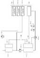
도 1은 본 발명의 실시 예에 따른 충전 제어 장치의 구성도.
도 2는 본 발명의 실시 예에 따른 충전 제어 방법의 순서도.
도 3은 본 발명의 실시 예에 따른 충전 제어 장치가 배터리팩을 충전하는 모습을 나타내는 예시도.1 is a block diagram of a charging control device according to an embodiment of the present invention.
2 is a flow chart of a charging control method according to an embodiment of the present invention.
3 is an exemplary view showing a state in which a charge control device charges a battery pack according to an embodiment of the present invention.
이하, 첨부된 도면을 참조하여 본 발명의 실시 예를 상세히 설명하기로 한 다. 그러나, 본 발명은 이하에서 개시되는 실시 예에 한정되는 것이 아니라 서로 다른 다양한 형태로 구현될 것이며, 단지 본 실시 예들은 본 발명의 개시가 완전하도록 하며, 통상의 지식을 가진 자에게 발명의 범주를 완전하게 알려주기 위해 제공되는 것이다.Hereinafter, embodiments of the present invention will be described in detail with reference to the accompanying drawings. However, the present invention is not limited to the embodiments disclosed below, but may be implemented in various forms, and only the embodiments are intended to complete the disclosure of the present invention and to those skilled in the art. It is provided for complete information.
본 발명의 실시 예에 따른 배터리팩은 전기 에너지를 저장하고 제공한다. 이러한 배터리는 충전 및 방전 가능한 복수의 배터리 셀을 포함할 수 있다. 또한, 배터리팩의 소정 수의 배터리 셀은 배터리 모듈을 이룰 수 있다. 즉, 배터리팩은 적어도 하나의 배터리 모듈을 포함할 수 있고, 배터리 모듈은 복수의 배터리 셀을 포함할 수 있다. 복수의 배터리 모듈은 배터리팩이나 부하 등의 스펙(specification)에 부합되도록 다양한 방법으로 직렬 및/또는 병렬 연결될 수 있고, 복수의 배터리 셀 또한 직렬 및/또는 병렬 연결될 수 있다. 여기서, 배터리 셀의 종류는 특별히 한정되지 않으며, 예컨대 리튬 이온 전지, 리튬 폴리머 전지, 니켈 카드뮴 전지, 니켈 수소 전지, 니켈 아연 전지 등으로 구성할 수 있다.The battery pack according to an embodiment of the present invention stores and provides electrical energy. Such a battery may include a plurality of battery cells that can be charged and discharged. In addition, a predetermined number of battery cells of a battery pack may constitute a battery module. That is, the battery pack may include at least one battery module, and the battery module may include a plurality of battery cells. The plurality of battery modules may be connected in series and / or in parallel in various ways so as to meet specifications such as battery packs or loads, and the plurality of battery cells may also be connected in series and / or in parallel. Here, the type of battery cell is not particularly limited, and for example, it can be constituted by a lithium ion battery, a lithium polymer battery, a nickel cadmium battery, a nickel hydrogen battery, a nickel zinc battery and the like.
본 발명의 실시 예에 따른 배터리팩을 구성하는 배터리 모듈은 정전압(constant voltage mode) 충전방식으로 충전될 수 있다. 정전압 충전 방식은 배터리팩에 구비된 적어도 하나의 배터리 모듈의 전압이 소정의 전압에 도달할 때까지 최대 전압의 충전 전원으로 충전을 실행하고, 배터리 모듈의 전압이 소정의 전압에 도달하게 되면, 배터리팩에 공급되는 충전 전원의 전압을 감소시키면서 배터리팩의 충전이 미완료된 적어도 하나의 배터리 모듈을 대상으로 충전을 실행하는 방법이다.The battery module constituting the battery pack according to an embodiment of the present invention may be charged in a constant voltage mode. In the constant voltage charging method, charging is performed using the charging power of the maximum voltage until the voltage of at least one battery module included in the battery pack reaches a predetermined voltage, and when the voltage of the battery module reaches the predetermined voltage, the battery A method of performing charging on at least one battery module in which charging of the battery pack is not completed while reducing the voltage of the charging power supplied to the pack.
본 발명의 실시 예에 따른 정전류 충전 제한 전압은 배터리 모듈을 구성하는 배터리 셀이 포화되기 직전의 상태에서 배터리 모듈에서 방전될 수 있는 최대 전압을 의미할 수 있다. 배터리 모듈이 정전류 충전 제한 전압을 초과하여 충전이 진행되면, 배터리 모듈을 구성하는 배터리 셀의 손상이 발생하고 결과적으로 배터리팩에 열화가 발생한다.The constant current charge limit voltage according to an embodiment of the present invention may mean a maximum voltage that can be discharged from the battery module in a state immediately before saturation of the battery cells constituting the battery module. When the battery module is charged beyond the constant current charge limit voltage, damage to the battery cells constituting the battery module occurs, resulting in deterioration of the battery pack.
1. 본 발명의 실시 예에 따른 충전 제어 장치1. Charge control device according to an embodiment of the present invention
도 1은 본 발명의 실시 예에 따른 충전 제어 장치의 구성도이다.1 is a block diagram of a charging control device according to an embodiment of the present invention.
도 1을 참조하면, 본 발명의 본 발명의 실시 예에 따른 충전 제어 장치(100)는 배터리팩(110), AFE(Analog Front End)부(120), 충전 전원 공급부(130), FET부(140) 및 제어부(150)를 포함할 수 있다.Referring to FIG. 1, the
배터리팩(110)은 복수 개의 배터리 모듈들(111-1, 111-2, 111-n)을 포함할 수 있다.The
또한, 배터리팩(110)에 포함된 각각의 배터리 모듈(111-1, 111-2, 111-n)은 복수 개의 배터리셀들로 구성될 수 있다.In addition, each battery module 111-1, 111-2, and 111-n included in the
AFE부(120)는 복수 개의 AFE들(121-1,121-2,121-n)을 포함할 수 있다.The AFE
또한, AFE부(120)에 포함된 각각의 AFE(121-1,121-2,121-n)는 배터리팩(110)에 포함된 각각의 배터리 모듈(111-1, 111-2, 111-n)과 일대일로 대응되도록 전기적으로 서로 연결될 수 있다.In addition, each of the AFEs 121-1, 121-2, 121-n included in the
또한, AFE부(120)에 포함된 각각의 AFE(121-1,121-2,121-n)는 제어부(150)의 제어에 따라 일대일로 대응되는 배터리팩(110)에 포함된 각각의 배터리 모듈(111-1, 111-2, 111-n)을 대상으로 전류, 전압 및 온도를 실시간 측정할 수 있다.In addition, each of the AFEs 121-1, 121-2, 121-n included in the
또한, AFE부(120)는 각각의 AFE(121-1,121-2,121-n)를 통해 측정된 각각의 배터리 모듈(111-1, 111-2, 111-n)의 전류, 전압 및 온도를 제어부(150)로 실시간 전달할 수 있다.In addition, the
또한, AFE부(120)에 포함된 각각의 AFE(121-1,121-2,121-n)는 인접한 AFE와 격리(Isolation) 소자를 통해 서로 연결될 수 있다.In addition, each of the AFEs 121-1, 121-2, 121-n included in the
충전 전원 공급부(130)는 복수 개의 직류-직류 변환기들(131-1, 131-2, 131-n) 및 통신부(132)를 포함할 수 있다.The charging
충전 전원 공급부(130)의 통신부(132)는 제어부(150)로부터 충전 전원 선택 신호를 전달받을 수 있다. 여기서 충전 전원 선택 신호는 복수 개의 직류-직류 변환기들(131-1, 131-2, 131-n) 중 어느 하나를 선택하여 선택된 직류-직류 변환기를 통해 충전 전원을 공급하도록 명령하는 신호이다.The
충전 전원 공급부(130)에 포함된 복수 개의 직류-직류 변환기들(131-1, 131-2, 131-n)을 구성하는 각각의 직류-직류 변환기는 서로 다른 전압 값을 갖는 전원을 충전 전원으로 공급할 수 있다.Each DC-DC converter constituting the plurality of DC-DC converters 131-1, 131-2, and 131-n included in the charging
FET부(140)는 제어부(150)의 제어에 따라 복수 개의 FET(141-1, 141-2, 141-n) 중 적어도 하나의 동작을 제어하여 충전 전원의 전류를 차단하거나 도통시킬 수 있다.The
제어부(150)는 배터리팩(110), AFE(Analog Front End)부(120), 충전 전원 공급부(130) 및 FET부(140)의 동작을 제어할 수 있다.The
또한, 제어부(150)는 AFE부(120)에서 측정된 배터리팩(110)에 구비된 각각의 배터리 모듈(111-1, 111-2, 111-n)의 전류, 전압 및 온도를 실시간 전달받을 수 있다.In addition, the
그 후, 제어부(150)는 AFE부(120)로부터 전달받은 배터리팩(110)에 구비된 각각의 배터리 모듈(111-1, 111-2, 111-n)의 SOC(State Of Charge)를 실시간 산출할 수 있다.Thereafter, the
그 후, 제어부(150)는 산출된 SOC들을 크기가 큰 순서대로 정렬할 수 있다,Thereafter, the
그 후, 제어부(150)는 배터리팩(110)에 구비된 각각의 배터리 모듈(111-1, 111-2, 111-n) 중 정렬된 SOC들 중 최대 SOC에 대응되는 하나의 배터리 모듈을 선택할 수 있다.Thereafter, the
그 후, 제어부(150)는 선택된 배터리 모듈의 SOC를 고려하여 충전 전원 선택 신호를 생성할 수 있다. 여기서 충전 전원 선택 신호는 충전 전원 공급부(130)에 구비된 복수 개의 직류-직류 변환기들(131-1 131-2, 131-n)을 통해 출력될 수 있는 복수 개의 충전 전원들 중 어느 하나를 선택하여 해당 직류-직류 변환기를 통해 충전 전원을 공급하도록 충전 전원 공급부(130)의 통신부(132)에 명령하는 신호를 의미할 수 이다.Thereafter, the
또한, 제어부(150)는 선택된 배터리 모듈의 SOC 및 충전 전원 공급부(130)에 구비된 복수 개의 직류-직류 변환기들(131-1 131-2, 131-n) 각각의 충전 전원의 전압 값을 고려하여 충전 전원 선택 신호를 생성할 수 있다.In addition, the
그 후, 제어부(150)는 배터리팩(110)에 포함된 복수 개의 배터리 모듈(111-1, 111-2, 111-n)을 최대 SOC에 대응되는 하나의 배터리 모듈의 SOC의 정전압(Constant Voltage) 구간 직전까지 충전 전원 공급부(130)에 구비된 복수 개의 직류-직류 변환기들(131-1 131-2, 131-n)중 충전 전원 선택 신호에 의해 선택된 직류-직류 변환기의 특정 충전 전원으로 충전할 수 있다.Thereafter, the
그 후, 제어부(150)는 최대 SOC를 갖는 배터리 모듈의 정전류 충전 제한 전압을 초과하여 충전되었는지 판단할 수 있다.Thereafter, the
상기 판단 결과, 최대 SOC를 갖는 배터리 모듈의 정전류 충전 제한 전압을 초과하여 충전되지 않은 경우, 각각의 배터리 모듈(111-1, 111-2, 111-n)의 SOC를 실시간 산출하며, 배터리팩(110)에 구비된 복수 개의 배터리 모듈(111-1, 111-2, 111-n)을 대상으로 기존 충전 전원으로 충전을 유지할 수 있다.As a result of the determination, when the battery is not charged beyond the constant current charge limit voltage of the battery module having the maximum SOC, the SOC of each of the battery modules 111-1, 111-2, and 111-n is calculated in real time, and the battery pack ( Charging with the existing charging power may be maintained for the plurality of battery modules 111-1, 111-2, and 111-n provided in the 110.
최대 SOC를 갖는 배터리 모듈의 정전류 충전 제한 전압을 초과하여 충전된 경우, 제어부(150)는 FET부(140)에 구비된 복수 개의 FET(141-1. 141-2, 141-n)중 최대 SOC를 갖는 배터리 모듈이 충전 전원을 도통시키는 적어도 하나의 FET의 동작을 제어하여 최대 SOC를 갖는 배터리 모듈로 흐르는 충전 전류를 차단할 수 있다.In the case where the battery module is charged beyond the constant current charge limit voltage of the battery module having the maximum SOC, the
그 후, 제어부(150)는 배터리팩(110)에 구비된 복수 개의 배터리 모듈(111-1, 111-2, 111-n) 중 최대 SOC를 갖는 배터리 모듈을 제외한 나머지 배터리 모듈을 대상으로 다시 최대 SOC를 갖는 배터리 모듈을 선택할 수 있다.Thereafter, the
그 후, 제어부(150)는 선택된 배터리 모듈의 정전류 충전 제한 전압까지 충전 전원 공급부(130)에 구비된 복수 개의 직류-직류 변환기들(131-1 131-2, 131-n)중 이미 사용된 특정 전압 값과 다른 전압 값을 갖는 직류-직류 변환기를 통해 다른 충전 전원으로 나머지 배터리 모듈 중 최대 SOC를 갖는 배터리 모듈이 충전할 수 있다.Thereafter, the
그 후, 제어부(150)는 배터리팩(110)에 구비된 모든 배터리 모듈(111-1, 111-2, 111-n)의 정전류 충전 제한 전압까지 충전되었는지 판단할 수 있다.Thereafter, the
상기 판단 결과, 배터리팩(110)에 구비된 모든 배터리 모듈(111-1, 111-2, 111-n)의 정전류 충전 제한 전압까지 충전되지 않은 경우, 제어부(150)는 배터리팩(110)에 구비된 모든 배터리 모듈(111-1, 111-2, 111-n)의 정전류 충전 제한 전압까지 충전될 때까지 상술된 과정들을 반복 수행할 수 있다.As a result of the determination, when the
배터리팩(110)에 구비된 모든 배터리 모듈(111-1, 111-2, 111-n)의 정전류 충전 제한 전압까지 충전된 경우, 제어부(150)는 배터리팩(110)에 구비된 복수 개의 배터리 모듈들(111-1, 111-2, 111-n)의 충전이 완료되었음을 나타내는 충전 완료 신호를 생성할 수 있다.When the
그 후, 제어부(150)는 충전 전원 공급부(130)를 통해 공급되는 충전 전원에 의해 배터리팩(110)에 구비된 복수 개의 배터리 모듈들(111-1, 111-2, 111-n)이 과충전되는 것을 방지하기 위해 생성된 충전 완료 신호를 배터리팩(110)의 배터리 관리 시스템(BMS: Battery Management System)에 전송할 수 있다.Thereafter, the
배터리팩(110)의 배터리 관리 시스템은 제어부(150)로부터 충전 완료 신호를 수신 받은 경우, 배터리팩(110)의 보호 동작을 수행할 수 있다.When the battery management system of the
한편 상술된 본 발명의 실시 예에 따른 충전 제어 장치(100)는 배터리팩(110)에 구비된 복수 개의 배터리 모듈들(111-1, 111-2, 111-n)의 각각의 SOC를 실시간 산출한 후, 크기에 따라 SOC를 정렬하여 SOC가 큰 배터리 모듈을 순서대로 정전류 충전 제한 전압까지 충전이 완료되면, 완료된 배터리 모듈의 충전 전류를 차단하여 나머지 배터리 모듈의 충전을 실행하는 예를 들어 설명하였다.Meanwhile, the charging
하지만 본 발명의 실시 예에 따른 충전 제어 장치(100)는 이에 한정되지 않고, 충전 제어 장치(100)는 최대 SOC를 갖는 배터리 모듈이 미리 설정된 기준 SOC가 되는 지점까지 배터리팩(110)에 구비된 복수 개의 배터리 모듈들(111-1, 111-2, 111-n)을 대상으로 특정 충전 전원으로 충전을 진행한 후, 배터리팩(110)에 구비된 복수 개의 배터리 모듈들(111-1, 111-2, 111-n)의 각각의 SOC를 실시간 산출한 후, 크기에 따라 SOC를 정렬하고, SOC의 크기 순서대로 각각의 배터리 모듈을 순차적으로 해당 배터리 모듈의 정전류 충전 제한 전압까지 충전이 완료되도록 해당 배터리 모듈만 선택된 충전 전원으로 충전을 진행할 수 있다. 여기서 각각의 배터리 모듈의 충전에 사용되는 충전 전원들의 전압 값들은 서로 다른 값을 가질 수 있다.However, the
2. 본 발명의 실시 예에 따른 충전 제어 방법2. Charge control method according to an embodiment of the present invention
도 2는 본 발명의 실시 예에 따른 충전 제어 방법의 순서도이다.2 is a flowchart of a charging control method according to an exemplary embodiment of the present invention.
도 2를 참조하면, 본 발명의 실시 예에 따른 충전 제어 장치(100)의 제어부(150)는 배터리팩(110)에 구비된 각각의 배터리 모듈(111-1, 111-2, 111-n)의 전류, 전압 및 온도를 측정하여 각각의 배터리 모듈(111-1, 111-2, 111-n)의 SOC를 실시간 산출하는 단계를 수행할 수 있다(S210).Referring to FIG. 2, the
더욱 상세하게는, 제어부(150)는 AFE부(120)에서 측정된 배터리팩(110)에 구비된 각각의 배터리 모듈(111-1, 111-2, 111-n)의 전류, 전압 및 온도를 실시간 전달받아 배터리팩(110)에 구비된 각각의 배터리 모듈(111-1, 111-2, 111-n)의 SOC를 실시간 산출할 수 있다.In more detail, the
또한, 상기 SOC를 실시간 산출하는 단계(S210)는 다음과 같은 과정들을 더 포함할 수 있다. 제어부(150)는 산출된 SOC들을 크기가 큰 순서대로 정렬하는 단계를 수행할 수 있다. 그 후, 제어부(150)는 정렬된 SOC들 중 최대 SOC에 대응되는 하나의 배터리 모듈을 선택하는 단계를 수행할 수 있다. 그 후, 제어부(150)는 선택된 배터리 모듈의 SOC를 고려하여 충전 전원 선택 신호를 생성하는 단계를 수행할 수 있다. 그 후, 제어부(150)는 생성된 충전 전원 선택 신호를 충전 전원부(130)로 전달하여 충전 전원이 공급되도록 제어하는 단계를 수행할 수 있다.In addition, the step (S210) of calculating the SOC in real time may further include the following processes. The
그 후, 제어부(150)는 배터리팩(110)에 포함된 복수 개의 배터리 모듈(111-1, 111-2, 111-n)을 최대 SOC에 대응되는 하나의 배터리 모듈의 SOC의 정전압(Constant Voltage) 구간 직전까지 충전 전원 공급부(130)에 구비된 복수 개의 직류-직류 변환기들(131-1 131-2, 131-n)중 충전 전원 선택 신호에 의해 선택된 직류-직류 변환기의 특정 충전 전원으로 충전하는 단계를 수행할 수 있다(S220).Thereafter, the
그 후, 제어부(150)는 최대 SOC를 갖는 배터리 모듈의 정전류 충전 제한 전압을 초과하여 충전되었는지 판단하는 단계를 수행할 수 있다(S230).Thereafter, the
상기 판단 결과, 최대 SOC를 갖는 배터리 모듈의 정전류 충전 제한 전압을 초과하여 충전되지 않은 경우, 상기 S220 단계로 복귀하여 해당 단계를 수행할 수 있다.As a result of the determination, when the battery is not charged beyond the constant current charge limit voltage of the battery module having the maximum SOC, the process returns to the step S220 to perform the corresponding step.
최대 SOC를 갖는 배터리 모듈의 정전류 충전 제한 전압을 초과하여 충전된 경우, 제어부(150)는 FET부(140)에 구비된 복수 개의 FET(141-1. 141-2, 141-n)중 최대 SOC를 갖는 배터리 모듈이 충전 전원을 도통시키는 적어도 하나의 FET의 동작을 제어하여 최대 SOC를 갖는 배터리 모듈로 흐르는 충전 전류를 차단하는 단계를 수행할 수 있다(S240).In the case where the battery module is charged beyond the constant current charge limit voltage of the battery module having the maximum SOC, the
그 후, 제어부(150)는 배터리팩(110)에 구비된 복수 개의 배터리 모듈(111-1, 111-2, 111-n) 중 최대 SOC를 갖는 배터리 모듈을 제외한 나머지 배터리 모듈을 대상으로 다시 최대 SOC를 갖는 배터리 모듈을 선택하고, 선택된 배터리 모듈의 정전류 충전 제한 전압까지 충전 전원 공급부(130)에 구비된 복수 개의 직류-직류 변환기들(131-1 131-2, 131-n)중 이미 사용된 특정 전압 값과 다른 전압 값을 갖는 직류-직류 변환기를 통해 다른 충전 전원으로 나머지 배터리 모듈 중 최대 SOC를 갖는 배터리 모듈이 충전하는 단계를 수행할 수 있다(S250).Thereafter, the
그 후, 제어부(150)는 배터리팩(110)에 구비된 모든 배터리 모듈(111-1, 111-2, 111-n)의 정전류 충전 제한 전압까지 충전되었는지 판단할 수 있다(S260).Thereafter, the
상기 판단 결과, 배터리팩(110)에 구비된 모든 배터리 모듈(111-1, 111-2, 111-n)의 정전류 충전 제한 전압까지 충전되지 않은 경우, 상기 S210 단계로 복귀하여 해당 단계를 수행할 수 있다.As a result of the determination, when the
배터리팩(110)에 구비된 모든 배터리 모듈(111-1, 111-2, 111-n)의 정전류 충전 제한 전압까지 충전된 경우, 제어부(150)는 충전 제어 동작을 종료할 수 있다.When the
또한, 제어부(150)는 배터리팩(110)에 구비된 모든 배터리 모듈(111-1, 111-2, 111-n)의 정전류 충전 제한 전압까지 충전된 경우, 배터리팩(110)에 구비된 복수 개의 배터리 모듈들(111-1, 111-2, 111-n)의 충전이 완료되었음을 나타내는 충전 완료 신호를 생성하는 단계를 수행할 수 있다.In addition, when the
그 후, 제어부(150)는 충전 전원 공급부(130)를 통해 공급되는 충전 전원에 의해 배터리팩(110)에 구비된 복수 개의 배터리 모듈들(111-1, 111-2, 111-n)이 과충전되는 것을 방지하기 위해 생성된 충전 완료 신호를 배터리팩(110)의 배터리 관리 시스템(BMS: Battery Management System)에 전송할 수 있다.Thereafter, the
3. 본 발명의 실시 예들에 따른 충전 제어 장치의 충전 동작3. Charging operation of the charging control device according to the embodiments of the present invention
도 3은 본 발명의 실시 예들에 따른 충전 제어 장치가 배터리팩을 충전하는 모습을 나타내는 예시도이다.3 is an exemplary view illustrating a charging control device charging a battery pack according to embodiments of the present disclosure.
도 3(a) 내지 도3(c)를 참조하면, 본 발명의 실시 예들에 따른 충전 제어 장치(100)의 제어부(150)는 AFE부(120)에 구비된 제1 AFE(121-1)의 동작을 제어하여 배터리팩(110)의 제1 배터리 모듈(111-1)의 전류, 전압 및 온도를 실시간 측정하여 제1 배터리 모듈(111-1)의 SOC를 산출할 수 있다.3 (a) to 3 (c), the
또한, 제어부(150)는 AFE부(120)에 구비된 제2 AFE(121-2)의 동작을 제어하여 배터리팩(110)의 제2 배터리 모듈(111-2)의 전류, 전압 및 온도를 실시간 측정하여 제2 배터리 모듈(111-1)의 SOC를 산출할 수 있다.In addition, the
AFE부(120)에 구비된 제1 AFE(121-1)와 제2 AFE(121-2)는 격리 소자(160)를 통해 서로 연결될 수 있다.The first AFE 121-1 and the second AFE 121-2 provided in the
도 3(a)는 본 발명의 실시 예들에 따른 충전 제어 장치가 배터리팩의 제1 및 제2 배터리 모듈들을 동시에 충전하는 모습을 나타내는 예시도이다.3A is an exemplary view illustrating a state in which a charge control device according to embodiments of the present invention simultaneously charges first and second battery modules of a battery pack.
도 3(a)을 참조하면, 본 발명의 실시 예들에 따른 충전 제어 장치(100)의 제어부(150)는 AFE부(120)에서 측정된 제1 및 제2 배터리 모듈(111-1, 111-2)의 전류, 전압 및 온도를 전달받아 각 배터리 모듈의 SOC들을 실시간 산출할 수 있다Referring to FIG. 3A, the
그 후, 제어부(150)는 산출된 SOC들 중 최대 SOC에 대응되는 배터리 모듈(111-1)을 선택할 수 있다.Thereafter, the
그 후, 제어부(150)는 제1 배터리 모듈(111-1)의 정전류 충전 제한 전압까지 충전 전원 공급부(130)의 제1 직류-직류 변환기(131-1)의 충전 전원으로 배터리팩(110)에 구비된 제1 및 제2 배터리 모듈(111-1, 111-2)을 충전할 수 있다. 이때 FET부(140)의 제1 FET(141-1), 제2 FET(141-2) 및 제4 FET(141-4)는 충전 전원의 전류가 도통되도록 동작이 제어부(150)의 제어에 따라 제어될 수 있다.Thereafter, the
도 3(b)는 본 발명의 실시 예들에 따른 충전 제어 장치가 배터리팩의 제1 모듈을 충전하는 모습을 나타내는 예시도이다.3 (b) is an exemplary view showing a state in which a charging control device charges a first module of a battery pack according to embodiments of the present invention.
도 3(b)를 참조하면, 본 발명의 실시 예들에 따른 충전 제어 장치(100)의 제어부(150)는 제1 배터리 모듈(111-1)의 SOC가 미리 설정된 기준 값까지 충전된 후, 제1 배터리 모듈(111-1)을 제1 배터리 모듈(111-1)의 정전류 충전 제한 전압까지 제1 및 제2 배터리 모듈(111-1, 111-2)의 충전에 사용된 전원과 다른 전압 값을 갖는 제2 직류-직류 변환기(131-2)의 충전 전원으로 충전할 수 있다.Referring to FIG. 3B, after the
이때 FET부(140)의 제2 FET(141-2) 및 제4 FET(141-4)는 충전 전원의 전류가 차단되도록 동작이 제어부(150)의 제어에 따라 제어되며, 제1 FET(141-1) 및 제3 FET(141-3)는 충전 전원의 전류가 도통되도록 동작이 제어부(150)의 제어에 따라 제어될 수 있다.At this time, the operation of the second FET 141-2 and the fourth FET 141-4 of the
도 3(c)는 본 발명의 실시 예들에 따른 충전 제어 장치가 배터리팩의 제2 모듈을 충전하는 모습을 나타내는 예시도이다.3 (c) is an exemplary view illustrating a state in which a charge control device according to embodiments of the present invention charges a second module of a battery pack.
도 3(c)를 참조하면, 본 발명의 실시 예들에 따른 충전 제어 장치(100)의 제어부(150)는 제1 배터리 모듈(111-1)의 SOC가 정전류 충전 제한 전압까지 충전이 완료된 후, 제1 배터리 모듈(111-1)의 충전에 사용된 충전 전원과 다른 전압 값을 갖는 제3 직류-직류 변환기(131-3)의 충전 전원으로 제2 배터리 모듈(111-2)을 제2 배터리 모듈(111-2)의 정전류 충전 제한 전압까지 충전할 수 있다.Referring to FIG. 3C, after the
이때 FET부(140)의 제1 FET(141-1) 및 제3 FET(141-3)는 충전 전원의 전류가 차단되도록 동작이 제어부(150)의 제어에 따라 제어되며, 제2 FET(141-2) 및 제4 FET(141-4)는 충전 전원의 전류가 도통되도록 동작이 제어부(150)의 제어에 따라 제어될 수 있다.At this time, the operation of the first FET 141-1 and the third FET 141-3 of the
한편, 본 발명의 기술적 사상은 상기 실시 예에 따라 구체적으로 기술되었으나, 상기 실시 예는 그 설명을 위한 것이며, 그 제한을 위한 것이 아님을 주지해야 한다. 또한, 본 발명의 기술분야에서 당업자는 본 발명의 기술 사상의 범위 내에서 다양한 실시 예가 가능함을 이해할 수 있을 것이다.On the other hand, although the technical spirit of the present invention has been described in detail according to the above embodiment, it should be noted that the above embodiment is for the purpose of explanation and not for the limitation. In addition, those skilled in the art will understand that various embodiments are possible within the scope of the technical idea of the present invention.
100: 충전 제어 장치110: 배터리팩
111-1: 제1 배터리 모듈111-2: 제2 배터리 모듈
111-n: 제n 배터리 모듈120: AFE부
121-1: 제1 AFE121-2: 제2 AFE
121-n: 제n AFE130: 충전 전원 공급부
131-1: 제1 직류-직류 변환기131-2: 제2 직류-직류 변환기
131-n: 제n 직류-직류 변환기132: 통신부
140: FET부140-1: 제1 FET
140-2: 제2 FET 140-n: 제n FET
150: 제어부100: charge control device 110: battery pack
111-1: First Battery Module 111-2: Second Battery Module
111-n: n-th battery module 120: AFE unit
121-1: First AFE 121-2: Second AFE
121-n: Control AFE 130: Charging power supply
131-1: First DC-DC Converter 131-2: Second DC-DC Converter
131-n: n-th DC-DC converter 132: communication unit
140: FET section 140-1: first FET
140-2: second FET 140-n: n-th FET
150: control unit
Claims (9)
Translated fromKorean상기 복수 개의 배터리 모듈들을 구성하는 각각의 배터리 모듈의 전류, 전압 및 온도를 측정하는 AFE(Analog Front End)부;
상기 AFE부로부터 상기 전류, 전압 및 온도를 전달받아 상기 각각의 배터리 모듈의 SOC(State Of Charge)를 실시간 산출하고, 상기 복수 개의 배터리 모듈 중 최대 SOC를 갖는 배터리 모듈의 SOC의 정전압(Constant Voltage) 구간 직전까지 복수 개의 충전 전원들 중 특정 전압 값을 갖는 특정 충전 전원으로 상기 복수 개의 배터리 모듈들을 충전하고, 상기 최대 SOC를 갖는 배터리 모듈의 SOC가 소정의 해당 정전류 충전 제한 전압을 넘어서 충전되는 경우, 상기 최대 SOC를 갖는 배터리 모듈로 흐르는 충전 전류를 차단하며, 상기 최대 SOC를 갖는 배터리 모듈을 제외한 나머지 배터리 모듈 중 최대 SOC를 갖는 배터리 모듈의 해당 정전류 충전 제한 전압까지 상기 복수 개의 충전 전원들 중 상기 특정 전압 값과 다른 전압 값을 갖는 다른 충전 전원으로 상기 나머지 배터리 모듈 중 최대 SOC를 갖는 배터리 모듈이 충전되도록 제어하는 제어부; 및
서로 다른 전압 값을 가진 상기 복수 개의 충전 전원을 출력하는 복수 개의 직류-직류 변환기들로 구성되는 충전 전원 공급부; 를 포함하는 충전 제어 장치.
In the charge control device for charging a battery pack connected in series a plurality of battery modules,
An analog front end (AFE) unit configured to measure current, voltage, and temperature of each battery module constituting the plurality of battery modules;
Receives the current, voltage and temperature from the AFE unit to calculate a state of charge (SOC) of each battery module in real time, and the constant voltage of the SOC of the battery module having the maximum SOC of the plurality of battery modules (Constant Voltage) When the plurality of battery modules are charged with a specific charging power source having a specific voltage value among the plurality of charging power sources until just before a section, and the SOC of the battery module having the maximum SOC is charged beyond a predetermined corresponding constant current charging limit voltage. The charging current flowing to the battery module having the maximum SOC is cut off, and the specific one of the plurality of charging power supplies to the corresponding constant current charging limit voltage of the battery module having the maximum SOC among the battery modules except the battery module having the maximum SOC. The remaining battery module with a different charging power source having a voltage value different from the voltage value Of the control unit for controlling such that the charged battery modules having the maximum SOC; And
A charging power supply comprising a plurality of DC-DC converters for outputting the plurality of charging powers having different voltage values; Charge control device comprising a.
상기 각각의 배터리 모듈의 SOC를 실시간 산출한 후, 상기 산출된 SOC를 크기가 큰 순서대로 정렬하고, 상기 복수 개의 배터리 모듈들 중 상기 정렬된 SOC 중 최대 SOC에 대응되는 배터리 모듈을 선택하며, 상기 선택된 배터리 모듈의 SOC를 고려하여 상기 충전 전원 공급부의 상기 복수 개의 충전 전원들 중 어느 하나를 선택하는 충전 전원 선택 신호를 생성하고, 상기 생성된 충전 전원 선택 신호를 상기 충전 전원 공급부로 전달하는 충전 제어 장치.
The method according to claim 1, wherein the control unit,
After calculating SOC of each of the battery modules in real time, the calculated SOCs are arranged in order of increasing size, and a battery module corresponding to the maximum SOC among the aligned SOCs is selected from the plurality of battery modules, A charging control for generating a charging power selection signal for selecting any one of the plurality of charging powers of the charging power supply unit in consideration of the SOC of the selected battery module, and transferring the generated charging power selection signal to the charging power supply unit. Device.
상기 복수 개의 배터리 모듈들이 각각 해당 정전류 충전 제한 전압까지 충전이 완료된 경우, 상기 복수 개의 배터리 모듈들의 충전이 완료되었음을 나타내는 충전 완료 신호를 생성하고, 상기 충전 전원 공급부를 통해 공급되는 충전 전원에 의해 상기 복수 개의 배터리 모듈들이 과충전되는 것을 방지하기 위해 생성된 상기 충전 완료 신호를 상기 배터리팩의 배터리 관리 시스템(Battery Management System)에 전송하는 충전 제어 장치.
The method according to claim 1, wherein the control unit,
When each of the plurality of battery modules is charged to the corresponding constant current charge limit voltage, the plurality of battery modules generate a charge completion signal indicating that the charging of the plurality of battery modules is completed, and the plurality of charge powers are supplied by the charging power supply unit. The charging control device for transmitting the generated charge completion signal to the battery management system (Battery Management System) of the battery pack to prevent the two battery modules are overcharged.
상기 제어부로부터 상기 충전 전원 선택 신호를 전달받는 통신부를 더 포함하며, 수신된 상기 충전 전원 선택 신호에 따라 상기 복수 개의 직류-직류 변환기들 중 하나를 선택하여 충전 전원을 출력하는 충전 제어 장치.
The method of claim 2, wherein the charging power supply unit,
And a communication unit configured to receive the charging power selection signal from the control unit, and outputs charging power by selecting one of the plurality of DC-DC converters according to the received charging power selection signal.
상기 복수 개의 배터리 모듈들과 일대일로 대응되는 복수 개의 AFE들을 포함하는 충전 제어 장치.
The method of claim 1, wherein the AFE unit,
A charging control device comprising a plurality of AFEs that correspond one-to-one with the plurality of battery modules.
상기 복수 개의 AFE들을 구성하는 각각의 AFE는 인접한 AFE 소자와 격리(Isolation) 소자를 통해 서로 연결되는 충전 제어 장치.
The method according to claim 5,
Each AFE constituting the plurality of AFEs is connected to each other via an adjacent AFE element and isolation element.
상기 복수 개의 배터리 모듈들을 구성하는 각각의 배터리 모듈의 전류, 전압 및 온도를 측정하여 상기 각각의 배터리 모듈의 SOC(State Of Charge)를 실시간 산출하는 제1 단계;
상기 복수 개의 배터리 모듈 중 최대 SOC를 갖는 배터리 모듈의 SOC의 정전압(Constant Voltage) 구간 직전까지 상기 복수 개의 배터리 모듈들을 복수 개의 충전 전원들 중 특정 전압 값을 갖는 특정 충전 전원으로 충전하는 제2 단계;
상기 최대 SOC를 갖는 배터리 모듈의 SOC가 소정의 해당 정전류 충전 제한 전압을 초과하여 충전되는 경우, 상기 최대 SOC를 갖는 배터리 모듈로 흐르는 충전 전류를 차단하는 제3 단계;
상기 최대 SOC를 갖는 배터리 모듈을 제외한 나머지 배터리 모듈 중 최대 SOC를 갖는 배터리 모듈의 해당 정전류 충전 제한 전압까지 상기 최대 SOC를 갖는 배터리 모듈을 제외한 나머지 배터리 모듈 중 최대 SOC를 갖는 배터리 모듈을 상기 복수 개의 충전 전원들 중 상기 특정 전압 값과 다른 전압 값을 갖는 다른 충전 전원으로 충전하는 제4 단계; 및
상기 각각의 배터리 모듈이 정전류 충전 제한 전압까지 충전이 완료될 때까지 상기 제1 단계 내지 제4 단계를 반복 수행하는 제5 단계;
를 포함하는 충전 제어 방법.
In the charging control method for charging a battery pack connected in series with a plurality of battery modules,
A first step of calculating a state of charge (SOC) of each battery module in real time by measuring current, voltage, and temperature of each battery module constituting the plurality of battery modules;
A second step of charging the plurality of battery modules with a specific charging power source having a specific voltage value among a plurality of charging power sources until immediately before a constant voltage section of the SOC of the battery module having the maximum SOC among the plurality of battery modules;
A third step of blocking a charging current flowing to the battery module having the maximum SOC when the SOC of the battery module having the maximum SOC is charged above a predetermined corresponding constant current charging limit voltage;
The plurality of charging of the battery module having the maximum SOC among the remaining battery modules except the battery module having the maximum SOC up to a corresponding constant current charge limit voltage of the battery module having the maximum SOC among the remaining battery modules except the battery module having the maximum SOC A fourth step of charging with another charging power source having a voltage value different from the specific voltage value among power sources; And
A fifth step of repeatedly performing the first to fourth steps until each of the battery modules is fully charged to the constant current charge limit voltage;
Charge control method comprising a.
상기 산출된 SOC를 크기가 큰 순서대로 정렬하는 단계;
상기 복수 개의 배터리 모듈들 중 상기 정렬된 SOC 중 최대 SOC에 대응되는 배터리 모듈을 선택하는 단계;
상기 선택된 배터리 모듈의 SOC를 고려하여 상기 복수 개의 충전 전원들 중 어느 하나를 선택하는 충전 전원 선택 신호를 생성하는 단계; 및
상기 생성된 충전 전원 선택 신호를 구비된 충전 전원 공급부로 전달하여, 상기 충전 전원이 공급되도록 제어하는 단계;
를 더 포함하는 충전 제어 방법.
The method of claim 7, wherein the first step,
Sorting the calculated SOCs in order of increasing size;
Selecting a battery module corresponding to a maximum SOC among the aligned SOCs among the plurality of battery modules;
Generating a charging power selection signal for selecting any one of the plurality of charging power sources in consideration of the SOC of the selected battery module; And
Transmitting the generated charging power selection signal to a charging power supply unit to control the charging power to be supplied;
Charge control method further comprising.
상기 각각의 배터리 모듈이 해당 정전류 충전 제한 전압까지 충전이 완료되었는지 판단하는 제6 단계;
상기 판단 결과, 상기 각각의 배터리 모듈이 해당 정전류 충전 제한 전압까지 충전이 완료된 경우, 상기 복수 개의 배터리 모듈들의 충전이 완료되었음을 나타내는 충전 완료 신호를 생성하는 단계; 및
구비된 충전 전원 공급부를 통해 공급되는 충전 전원에 의해 상기 복수 개의 배터리 모듈들이 과충전되는 것을 방지하기 위해 생성된 상기 충전 완료 신호를 상기 배터리팩의 배터리 관리 시스템(Battery Management System)에 전송하는 단계;
를 더 포함하는 충전 제어 방법.The method according to claim 7, after the fifth step,
A sixth step in which each of the battery modules determines whether charging is completed to a corresponding constant current charging limit voltage;
Generating a charge completion signal indicating that the charging of the plurality of battery modules is completed when each of the battery modules is charged to the corresponding constant current charge limit voltage; And
Transmitting the charge completion signal generated to prevent the plurality of battery modules from being overcharged by the charging power supplied through the provided charging power supply unit to a battery management system of the battery pack;
Charge control method further comprising.
Priority Applications (1)
| Application Number | Priority Date | Filing Date | Title |
|---|---|---|---|
| KR1020150099049AKR102025287B1 (en) | 2015-07-13 | 2015-07-13 | Control device and method for chare |
Applications Claiming Priority (1)
| Application Number | Priority Date | Filing Date | Title |
|---|---|---|---|
| KR1020150099049AKR102025287B1 (en) | 2015-07-13 | 2015-07-13 | Control device and method for chare |
Publications (2)
| Publication Number | Publication Date |
|---|---|
| KR20170007960A KR20170007960A (en) | 2017-01-23 |
| KR102025287B1true KR102025287B1 (en) | 2019-09-26 |
Family
ID=57989735
Family Applications (1)
| Application Number | Title | Priority Date | Filing Date |
|---|---|---|---|
| KR1020150099049AActiveKR102025287B1 (en) | 2015-07-13 | 2015-07-13 | Control device and method for chare |
Country Status (1)
| Country | Link |
|---|---|
| KR (1) | KR102025287B1 (en) |
Families Citing this family (5)
| Publication number | Priority date | Publication date | Assignee | Title |
|---|---|---|---|---|
| KR102252799B1 (en) | 2018-04-11 | 2021-05-17 | 주식회사 케이티 | Power conversion system and energy storage system for charging or discharging energy ouput from power plant |
| CN109599911B (en)* | 2018-11-12 | 2023-04-11 | 苏州华启智能科技有限公司 | Voltage-stabilizing output-adjustable rapid charging standby power supply |
| KR102785624B1 (en) | 2019-08-23 | 2025-03-25 | 주식회사 엘지에너지솔루션 | Cell stabilization method and system of energy storage system (ESS) |
| KR102318170B1 (en)* | 2020-08-20 | 2021-10-27 | 김용철 | Energy storage system using battery pack |
| US12311801B2 (en) | 2020-12-16 | 2025-05-27 | Yong Chul Kim | Energy storage system employing battery packs |
Family Cites Families (4)
| Publication number | Priority date | Publication date | Assignee | Title |
|---|---|---|---|---|
| KR20030092391A (en)* | 2002-05-29 | 2003-12-06 | 현대자동차주식회사 | Battery pack charging controlling device of electric vehicle and method thereof |
| KR100471238B1 (en) | 2002-07-08 | 2005-03-10 | 현대자동차주식회사 | Method of estimat ing state of charge for battery pack in a hybrid electric vehicle |
| TWM404155U (en)* | 2010-08-16 | 2011-05-21 | Sunyen Co Ltd | Electricity charger of the electric car |
| KR101241277B1 (en)* | 2011-07-14 | 2013-03-15 | 주식회사 로보테크 | System for charging with multi channel automatic switching and method for the same |
- 2015
- 2015-07-13KRKR1020150099049Apatent/KR102025287B1/enactiveActive
Also Published As
| Publication number | Publication date |
|---|---|
| KR20170007960A (en) | 2017-01-23 |
Similar Documents
| Publication | Publication Date | Title |
|---|---|---|
| US11128158B2 (en) | Battery management system and related techniques for adaptive, dynamic control of battery charging | |
| CN105518924B (en) | Battery apparatus and electric vehicle | |
| KR102516355B1 (en) | Method and apparatus of controlling battery, and battery pack enabling the method | |
| KR101288122B1 (en) | Battery charging method, and battery pack being applied the method | |
| JP4237804B2 (en) | Battery pack protection device and battery pack device | |
| KR101975395B1 (en) | Battery pack, and controlling method of the same | |
| KR102025287B1 (en) | Control device and method for chare | |
| KR101241532B1 (en) | Battery charging apparatus for changing a charging voltage adaptively and battery charging control method thereof | |
| US20160187431A1 (en) | Storage battery, storage-battery evaluating device, and storage-battery evaluating method | |
| US9472960B2 (en) | Regulating device, battery assembly device and regulating method | |
| US20190157896A1 (en) | Battery management apparatus and method for protecting a lithium iron phosphate cell from over-voltage using the same | |
| KR102429438B1 (en) | A Hybrid Method with Serial and Parallel Charging Apparatus for Balanced Charging of EV Batteries | |
| CN101841176A (en) | Charging method and charging system | |
| KR20170022162A (en) | Multi battery pack apparatus and method of controlling the same | |
| US20200408845A1 (en) | Cell balance control device and cell balance control system | |
| US20200006960A1 (en) | Charging device and method thereof | |
| KR101614046B1 (en) | Apparatus for managing battery system | |
| KR102082382B1 (en) | Multi battery pack apparatus and control method for charging the same | |
| KR102285148B1 (en) | Battery charging method and battery charging apparatus using the same | |
| US11050267B2 (en) | Power supply system | |
| KR102574696B1 (en) | Energy storage system and operation method thereof | |
| KR102035674B1 (en) | Apparatus and method for voltage balancing of battery modules | |
| US20130314053A1 (en) | Battery management unit | |
| KR102860353B1 (en) | Energy Emission Apparatus and Method through Cell Balancing Circuit and Pack Discharge Circuit in the event of isolation resistance Failure | |
| KR101848010B1 (en) | System for controlling discharge or charge of battery and therefor |
Legal Events
| Date | Code | Title | Description |
|---|---|---|---|
| PA0109 | Patent application | Patent event code:PA01091R01D Comment text:Patent Application Patent event date:20150713 | |
| PG1501 | Laying open of application | ||
| A201 | Request for examination | ||
| PA0201 | Request for examination | Patent event code:PA02012R01D Patent event date:20180123 Comment text:Request for Examination of Application Patent event code:PA02011R01I Patent event date:20150713 Comment text:Patent Application | |
| E902 | Notification of reason for refusal | ||
| PE0902 | Notice of grounds for rejection | Comment text:Notification of reason for refusal Patent event date:20190102 Patent event code:PE09021S01D | |
| E701 | Decision to grant or registration of patent right | ||
| PE0701 | Decision of registration | Patent event code:PE07011S01D Comment text:Decision to Grant Registration Patent event date:20190718 | |
| PR0701 | Registration of establishment | Comment text:Registration of Establishment Patent event date:20190919 Patent event code:PR07011E01D | |
| PR1002 | Payment of registration fee | Payment date:20190920 End annual number:3 Start annual number:1 | |
| PG1601 | Publication of registration | ||
| PR1001 | Payment of annual fee | Payment date:20220824 Start annual number:4 End annual number:4 | |
| PR1001 | Payment of annual fee | Payment date:20230627 Start annual number:5 End annual number:5 | |
| PR1001 | Payment of annual fee | Payment date:20250618 Start annual number:7 End annual number:7 |