KR102022964B1 - Apparatus for inspecting the inside of a structure - Google Patents
Apparatus for inspecting the inside of a structureDownload PDFInfo
- Publication number
- KR102022964B1 KR102022964B1KR1020180073352AKR20180073352AKR102022964B1KR 102022964 B1KR102022964 B1KR 102022964B1KR 1020180073352 AKR1020180073352 AKR 1020180073352AKR 20180073352 AKR20180073352 AKR 20180073352AKR 102022964 B1KR102022964 B1KR 102022964B1
- Authority
- KR
- South Korea
- Prior art keywords
- measurement
- dimensional
- unit
- lidar
- data
- Prior art date
- Legal status (The legal status is an assumption and is not a legal conclusion. Google has not performed a legal analysis and makes no representation as to the accuracy of the status listed.)
- Active
Links
Images


Classifications
- G—PHYSICS
- G01—MEASURING; TESTING
- G01B—MEASURING LENGTH, THICKNESS OR SIMILAR LINEAR DIMENSIONS; MEASURING ANGLES; MEASURING AREAS; MEASURING IRREGULARITIES OF SURFACES OR CONTOURS
- G01B11/00—Measuring arrangements characterised by the use of optical techniques
- G01B11/24—Measuring arrangements characterised by the use of optical techniques for measuring contours or curvatures
- G—PHYSICS
- G01—MEASURING; TESTING
- G01B—MEASURING LENGTH, THICKNESS OR SIMILAR LINEAR DIMENSIONS; MEASURING ANGLES; MEASURING AREAS; MEASURING IRREGULARITIES OF SURFACES OR CONTOURS
- G01B11/00—Measuring arrangements characterised by the use of optical techniques
- G01B11/16—Measuring arrangements characterised by the use of optical techniques for measuring the deformation in a solid, e.g. optical strain gauge
- G—PHYSICS
- G01—MEASURING; TESTING
- G01B—MEASURING LENGTH, THICKNESS OR SIMILAR LINEAR DIMENSIONS; MEASURING ANGLES; MEASURING AREAS; MEASURING IRREGULARITIES OF SURFACES OR CONTOURS
- G01B11/00—Measuring arrangements characterised by the use of optical techniques
- G01B11/30—Measuring arrangements characterised by the use of optical techniques for measuring roughness or irregularity of surfaces
- G—PHYSICS
- G01—MEASURING; TESTING
- G01S—RADIO DIRECTION-FINDING; RADIO NAVIGATION; DETERMINING DISTANCE OR VELOCITY BY USE OF RADIO WAVES; LOCATING OR PRESENCE-DETECTING BY USE OF THE REFLECTION OR RERADIATION OF RADIO WAVES; ANALOGOUS ARRANGEMENTS USING OTHER WAVES
- G01S7/00—Details of systems according to groups G01S13/00, G01S15/00, G01S17/00
- G01S7/48—Details of systems according to groups G01S13/00, G01S15/00, G01S17/00 of systems according to group G01S17/00
- G01S7/497—Means for monitoring or calibrating
- H—ELECTRICITY
- H04—ELECTRIC COMMUNICATION TECHNIQUE
- H04N—PICTORIAL COMMUNICATION, e.g. TELEVISION
- H04N13/00—Stereoscopic video systems; Multi-view video systems; Details thereof
- H04N13/20—Image signal generators
- H04N13/204—Image signal generators using stereoscopic image cameras
- H04N13/207—Image signal generators using stereoscopic image cameras using a single 2D image sensor
Landscapes
- Physics & Mathematics (AREA)
- General Physics & Mathematics (AREA)
- Engineering & Computer Science (AREA)
- Multimedia (AREA)
- Signal Processing (AREA)
- Computer Networks & Wireless Communication (AREA)
- Radar, Positioning & Navigation (AREA)
- Remote Sensing (AREA)
- Length Measuring Devices By Optical Means (AREA)
Abstract
Translated fromKoreanDescription
Translated fromKorean본 발명은 구조물 내부 점검 장치에 관한 것으로, 특히, 구조물 내부의 손상 상태를 점검하기 위한 구조물 내부 점검 장치에 관한 것이다.The present invention relates to an internal structure inspection apparatus, and more particularly, to an internal structure inspection apparatus for inspecting the damage state inside the structure.
구조물의 내부를 점검하는 것은 구조물 자체의 안전성 점검 이외에, 외부에서는 확인할 수 없는 구조물의 안쪽 부분을 점검하는 것으로, 구조물의 내부 손상 상태를 점검하여 보수의 필요 여부를 판단하는 것이다. 구조물의 내부 점검이 필요한 대표적인 구조물로는 노(furnace)가 있다.Inspecting the interior of the structure, in addition to the safety check of the structure itself, checks the inner part of the structure that cannot be identified from the outside, and checks the internal damage state of the structure to determine whether the repair is necessary. A typical structure that requires internal inspection of the structure is a furnace.
일반적으로 노(爐, furnace)는 원료를 넣고 열을 가하여 녹이거나 굽는 시설을 지칭하며, 일 예로 소각로 등이 존재한다. 이러한 소각로는 화학산업단지 등에서 각종 유해물질 분해를 위해 사용되는데, 내부에는 가해지는 열을 견디기 위한 내화벽돌 등의 내열구조가 적용된다. 이때, 내열 구조가 지속적으로 공급되는 열에 의해 손상되거나 무너지는 경우, 소각로의 효율이 저하될 뿐만 아니라, 외부로의 열전달로 인해 인적, 물적 피해가 발생할 수 있는 위험이 존재한다.In general, a furnace refers to a facility in which raw materials are added and heat is melted or baked. For example, an incinerator is present. Such incinerators are used to decompose various harmful substances in chemical industrial complexes, etc., and heat-resistant structures such as refractory bricks for enduring heat applied thereto are applied. At this time, when the heat-resistant structure is damaged or collapsed by the heat continuously supplied, not only the efficiency of the incinerator is lowered, but there is a risk that human and physical damage may occur due to heat transfer to the outside.
따라서, 이러한 위험을 방지하기 위해 내부의 내화벽돌 등의 내열구조에 대한 안전점검이 정기적으로 이루어진다. 소각로 내부 안전점검은 현재 소각로를 중지시키고 열을 방출시킨 후 일정 온도 이하로 내려가면 작업자가 내부에 들어가 직접 검사를 수행하는 방식을 사용하고 있다.Therefore, in order to prevent such a risk, safety checks on heat-resistant structures such as fire bricks inside are periodically performed. Incinerator safety inspection currently uses the method of stopping the incinerator, releasing heat, and lowering it below a certain temperature to allow workers to go inside and carry out the inspection directly.
하지만, 이 경우 작업자가 직접 검사를 위해 내부에 들어가기 때문에 소각로의 냉각까지 걸리는 시간이 증가할 뿐만 아니라 내부에서 휴먼 에러에 의한 오진 및 작업자의 낙상 사고 등이 발생할 수 있는 문제점이 존재한다.However, in this case, since the worker enters the interior for direct inspection, the time taken to cool the incinerator is increased, and there is a problem that a misunderstanding due to a human error and a fall accident of the worker may occur.
상기와 같은 문제점을 해결하기 위한 본 발명의 목적은, 구조물 내부의 손상 상태를 보다 안전하게 점검할 수 있으며, 시간 및 비용 소모를 감소시킬 수 있는 구조물 내부 점검 장치를 제공하는 것이다.SUMMARY OF THE INVENTION An object of the present invention for solving the above problems is to provide a structure inspection apparatus that can more safely check the damage state inside the structure, and can reduce time and cost.
위와 같은 과제를 해결하기 위한 본 발명의 일 실시예에 따른 구조물 내부 점검 장치는 구조물 내부의 상태를 측정하기 위하여, 상기 구조물 내부를 상하방향으로 이동하며 측정하는 3차원측정부; 상기 3차원측정부의 상기 구조물 내부에서의 상하방향 이동을 제어하고, 상기 3차원측정부의 측정 기준위치를 제어하는 위치제어부; 및 상기 3차원측정부로부터 측정 데이터 및 상기 위치제어부로부터 상기 3차원측정부의 측정 기준위치 데이터를 제공받아, 상기 구조물 내부의 형상을 분석하고, 상기 구조물 내부의 상태를 판단하는 3차원분석부;를 포함하는 것일 수 있다.In accordance with an embodiment of the present invention for solving the above problems, the apparatus for checking the interior of the structure, the three-dimensional measuring unit for measuring the inside of the structure to move in the vertical direction; A position control unit for controlling a vertical movement of the three-dimensional measurement unit inside the structure and controlling a measurement reference position of the three-dimensional measurement unit; And a three-dimensional analyzer configured to receive measurement data from the three-dimensional measuring unit and measurement reference position data of the three-dimensional measuring unit from the position control unit, analyze a shape inside the structure, and determine a state inside the structure. It may be to include.
여기에서, 상기 3차원측정부는 상기 구조물 내부의 영상을 촬영하기 위한 적어도 하나의 카메라; 상기 구조물 내부의 형상을 측정하기 위한 라이다(Lidar); 및 상기 라이다의 측정방향을 제어하기 위한 측정방향 제어 모듈;을 포함하는 것일 수 있다.Here, the three-dimensional measuring unit at least one camera for taking an image of the inside of the structure; Lidar for measuring the shape of the inside of the structure (Lidar); And a measuring direction control module for controlling the measuring direction of the lidar.
여기에서, 상기 3차원측정부는 상기 라이다의 측정방향을 수평방향과 평행하게 측정을 수행하며, 상기 구조물 내부에서 상기 라이다의 측정 거리 한계 및 음영구역 원인으로 측정이 되지 않는 구간에 대하여는, 상기 측정방향 제어 모듈을 이용하여, 상기 라이다의 측정방향을 수평방향과 미리 정해진 각도를 갖도록 변화시키고, 상기 라이다를 일정한 주기로 상기 측정 기준위치를 중심으로 회전시키면서 측정하는 것일 수 있다.Here, the three-dimensional measuring unit measures the measurement direction of the lidar in parallel with the horizontal direction, and for the section that is not measured due to the measurement distance limit and the shadow area of the lidar inside the structure, By using a measurement direction control module, the measurement direction of the lidar may be changed to have a predetermined angle with a horizontal direction, and the lidar may be measured while rotating about the measurement reference position at regular intervals.
여기에서, 상기 3차원분석부는 상기 측정방향 제어 모듈로부터 상기 라이다의 측정방향 변화 데이터 및 회전 데이터를 더 제공받아, 상기 구조물 내부의 형상을 분석하고, 상기 구조물 내부의 상태를 판단하는 것일 수 있다.The three-dimensional analysis unit may further receive measurement direction change data and rotation data of the lidar from the measurement direction control module to analyze the shape of the inside of the structure and determine a state inside the structure. .
여기에서, 상기 측정방향 제어 모듈은, 상기 라이다의 측정방향을 수평방향과 직교하도록 변화시키는 것일 수 있다.The measuring direction control module may change the measuring direction of the lidar to be orthogonal to the horizontal direction.
여기에서, 상기 3차원측정부로부터 제공받는 측정 데이터는 상기 적어도 하나의 카메라 영상 데이터 및 상기 라이다의 형상 데이터를 포함하며, 상기 3차원분석부는 상기 적어도 하나의 카메라 영상 데이터 및 상기 라이다의 형상 데이터를 결합하여 상기 구조물 내부의 형상을 분석하고, 상기 구조물 내부의 상태를 판단하는 것일 수 있다.Here, the measurement data provided from the three-dimensional measuring unit includes the at least one camera image data and the shape data of the lidar, wherein the three-dimensional analysis unit the shape of the at least one camera image data and the lidar By combining data, the shape of the structure may be analyzed and the state of the structure may be determined.
여기에서, 상기 위치제어부는 상기 3차원측정부와 연결되는 적어도 하나의 케이블을 포함하며, 상기 적어도 하나의 케이블을 이용하여, 상기 3차원측정부와 통신을 수행하고, 전원을 공급하는 것일 수 있다.Here, the position control unit may include at least one cable connected to the three-dimensional measuring unit, by using the at least one cable, the communication with the three-dimensional measuring unit may be to supply power. .
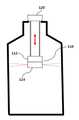
여기에서, 상기 위치제어부는 상기 3차원분석부의 상부로 미리 정해진 거리 이격되고, 상기 3차원분석부와 평행하게 구비되며, 광 투과가 가능한 반투명 패널;을 포함하며, 상기 반투명 패널에 미리 정해진 형상의 직진광을 전송하고, 상기 반투명 패널에 형성된 상기 직진광의 반사 형상을 이용하여 자세를 분석하는 것일 수 있다.Here, the position control unit comprises a translucent panel spaced apart a predetermined distance to the upper portion of the three-dimensional analysis unit, in parallel with the three-dimensional analysis unit, and capable of transmitting light, the translucent panel of a predetermined shape Transmitting the straight light, it may be to analyze the posture by using the reflection shape of the straight light formed on the translucent panel.
여기에서, 상기 반투명 패널은, 복수개의 광 반응 센서를 포함하며, 상기 광 반응 센서는, 상기 직진광의 도달 위치에 밀집되어 형성되는 것일 수 있다.The translucent panel may include a plurality of photoreaction sensors, and the photoreaction sensors may be densely formed at an arrival position of the straight light.
여기에서, 상기 3차원분석부는 외력 또는 외부 에너지로 인한 돌발 상황이 발생하는 경우, 상기 3차원 분석부의 동작을 정지시키는 것일 수 있다.Here, the three-dimensional analysis unit may be to stop the operation of the three-dimensional analysis unit when an accident occurs due to external force or external energy.
여기에서, 상기 3차원분석부는 저장 모듈을 더 포함하고, 상기 3차원측정부로부터 측정 데이터 및 상기 위치제어부로부터 상기 3차원측정부의 측정 기준위치 데이터를 제공받아 상기 저장 모듈에 저장함과 동시에 외부 서버로 전송하는 것일 수 있다.The three-dimensional analysis unit may further include a storage module. The measurement data may be received from the three-dimensional measurement unit and the measurement reference position data of the three-dimensional measurement unit may be stored from the three-dimensional measurement unit and stored in the storage module. It may be to transmit.
여기에서, 상기 구조물은 노(furnace)이며, 상기 상태 분석은 상기 노 내부의 안전성 여부를 분석하는 것일 수 있다.Here, the structure is a furnace (furnace), the condition analysis may be to analyze the safety of the interior of the furnace.
본 발명의 일 실시예에 따른 구조물 내부 점검 장치는 구조물 내부 점검 시 발생할 수 있는 인명 사고 위험을 감소시켜줄 수 있는 효과가 있다.The inspection device inside the structure according to an embodiment of the present invention has an effect that can reduce the risk of human accidents that may occur when the structure inside the inspection.
또, 본 발명의 일 실시예에 따른 구조물 내부 점검 장치는 작업자가 직접 들어가서 내부 점검을 수행할 때와 비교하여 오진 발생율을 감소시킬 수 있는 효과가 있다.In addition, the structure inspection apparatus according to an embodiment of the present invention has an effect that can reduce the occurrence rate of the dust compared to when the operator directly enters the interior inspection.
또한, 본 발명의 일 실시예에 따른 구조물 내부 점검 장치는 중력에 의해 발생할 수 있는 오차를 보정함으로써 내부 점검 시 발생할 수 있는 기계적 오차를 감소시킬 수 있는 효과가 있다.In addition, the internal structure inspection apparatus according to an embodiment of the present invention has the effect of reducing the mechanical error that may occur during the internal inspection by correcting the error that may occur by gravity.
또한, 본 발명의 일 실시예에 따른 구조물 내부 점검 장치는 높은 온도에서도 동작하여 안전점검시간을 대폭 단축시킴으로써 비용을 절감할 수 있는 효과가 있다.In addition, the inspection apparatus inside the structure according to an embodiment of the present invention has an effect that can operate at a high temperature to significantly reduce the safety inspection time by reducing the cost.
도 1은 본 발명의 일실시예에 따른 구조물 내부 점검 장치를 설명하기 위한 블록도이다.
도 2는 본 발명의 일실시예에 따른 구조물 내부 점검 장치를 설명하기 위한 개념도이다.
도 3은 본 발명의 일실시예에 따른 구조물 내부 점검 장치의 3차원측정부를 설명하기 위한 개념도이다.
도 4는 본 발명의 일실시예에 따른 구조물 내부 점검 장치의 3차원측정부에서 라이다의 동작을 설명하기 위한 도면이다.
도 5는 본 발명의 일실시예에 따른 구조물 내부 점검 장치의 3차원측정부에서 라이다의 측정방향 변화를 설명하기 위한 도면이다.
도 6은 본 발명의 일실시예에 따른 구조물 내부 점검 장치의 위치제어부의 반투명 패널을 설명하기 위한 도면이다.
도 7은 본 발명의 일실시예에 따른 구조물 내부 점검 장치의 3차원분석부를 설명하기 위한 블록도이다.1 is a block diagram illustrating a structure inspection apparatus according to an embodiment of the present invention.
2 is a conceptual diagram illustrating a structure inspection apparatus according to an embodiment of the present invention.
3 is a conceptual diagram illustrating a three-dimensional measuring unit of the structure inspection apparatus according to an embodiment of the present invention.
4 is a view for explaining the operation of the lidar in the three-dimensional measuring unit of the inspection apparatus inside the structure according to an embodiment of the present invention.
5 is a view for explaining a change in the measurement direction of the lidar in the three-dimensional measurement unit of the structure inspection apparatus according to an embodiment of the present invention.
6 is a view for explaining a translucent panel of the position control unit of the structure inspection apparatus according to an embodiment of the present invention.
7 is a block diagram illustrating a three-dimensional analysis unit of the structure inspection apparatus according to an embodiment of the present invention.
이하, 첨부한 도면을 참고로 하여 본 발명의 실시예에 대하여 본 발명이 속하는 기술 분야에서 통상의 지식을 가진 자가 용이하게 실시할 수 있도록 상세히 설명한다. 본 발명은 여러 가지 상이한 형태로 구현될 수 있으며 여기에서 설명하는 실시 예에 한정되지 않는다.Hereinafter, exemplary embodiments of the present invention will be described in detail with reference to the accompanying drawings so that those skilled in the art may easily implement the present invention. As those skilled in the art would realize, the described embodiments may be modified in various different ways, all without departing from the spirit or scope of the present invention.
본 발명을 명확하게 설명하기 위해서 설명과 관계없는 부분은 생략하였으며, 명세서 전체를 통하여 동일 또는 유사한 구성요소에 대해서는 동일한 참조 부호를 붙이도록 한다.In order to clearly describe the present invention, parts irrelevant to the description are omitted, and like reference numerals designate like elements throughout the specification.
명세서 전체에서, 어떤 부분이 다른 부분과 "연결"되어 있다고 할 때, 이는 "직접적으로 연결"되어 있는 경우뿐 아니라, 그 중간에 다른 소자를 사이에 두고 "전기적으로 연결"되어 있는 경우도 포함한다. 또한 어떤 부분이 어떤 구성요소를 "포함"한다고 할 때, 이는 특별히 반대되는 기재가 없는 한 다른 구성요소를 제외하는 것이 아니라 다른 구성요소를 더 포함할 수 있는 것을 의미한다.Throughout the specification, when a part is "connected" to another part, this includes not only "directly connected" but also "electrically connected" with another element in between. . In addition, when a part is said to "include" a certain component, which means that it may further include other components, except to exclude other components unless otherwise stated.
어느 부분이 다른 부분의 "위에" 있다고 언급하는 경우, 이는 바로 다른 부분의 위에 있을 수 있거나 그 사이에 다른 부분이 수반될 수 있다. 대조적으로 어느 부분이 다른 부분의 "바로 위에" 있다고 언급하는 경우, 그 사이에 다른 부분이 수반되지 않는다.When a portion is referred to as being "above" another portion, it may be just above the other portion or may be accompanied by another portion in between. In contrast, when a part is mentioned as "directly above" another part, no other part is involved between them.
제1, 제2 및 제3 등의 용어들은 다양한 부분, 성분, 영역, 층 및/또는 섹션들을 설명하기 위해 사용되나 이들에 한정되지 않는다. 이들 용어들은 어느 부분, 성분, 영역, 층 또는 섹션을 다른 부분, 성분, 영역, 층 또는 섹션과 구별하기 위해서만 사용된다. 따라서, 이하에서 서술하는 제1 부분, 성분, 영역, 층 또는 섹션은 본 발명의 범위를 벗어나지 않는 범위 내에서 제2 부분, 성분, 영역, 층 또는 섹션으로 언급될 수 있다.Terms such as first, second, and third are used to describe various parts, components, regions, layers, and / or sections, but are not limited to these. These terms are only used to distinguish one part, component, region, layer or section from another part, component, region, layer or section. Accordingly, the first portion, component, region, layer or section described below may be referred to as the second portion, component, region, layer or section without departing from the scope of the invention.
여기서 사용되는 전문 용어는 단지 특정 실시예를 언급하기 위한 것이며, 본 발명을 한정하는 것을 의도하지 않는다. 여기서 사용되는 단수 형태들은 문구들이 이와 명백히 반대의 의미를 나타내지 않는 한 복수 형태들도 포함한다. 명세서에서 사용되는 "포함하는"의 의미는 특정 특성, 영역, 정수, 단계, 동작, 요소 및/또는 성분을 구체화하며, 다른 특성, 영역, 정수, 단계, 동작, 요소 및/또는 성분의 존재나 부가를 제외시키는 것은 아니다.The terminology used herein is for reference only to specific embodiments and is not intended to limit the invention. As used herein, the singular forms “a,” “an,” and “the” include plural forms as well, unless the phrases clearly indicate the opposite. As used herein, the meaning of "comprising" embodies a particular characteristic, region, integer, step, operation, element and / or component, and the presence of other characteristics, region, integer, step, operation, element and / or component It does not exclude the addition.
"아래", "위" 등의 상대적인 공간을 나타내는 용어는 도면에서 도시된 한 부분의 다른 부분에 대한 관계를 보다 쉽게 설명하기 위해 사용될 수 있다. 이러한 용어들은 도면에서 의도한 의미와 함께 사용 중인 장치의 다른 의미나 동작을 포함하도록 의도된다. 예를 들면, 도면 중의 장치를 뒤집으면, 다른 부분들의 "아래"에 있는 것으로 설명된 어느 부분들은 다른 부분들의 "위"에 있는 것으로 설명된다. 따라서 "아래"라는 예시적인 용어는 위와 아래 방향을 전부 포함한다. 장치는 90˚ 회전 또는 다른 각도로 회전할 수 있고, 상대적인 공간을 나타내는 용어도 이에 따라서 해석된다.Terms indicating relative space such as "below" and "above" may be used to more easily explain the relationship of one part to another part shown in the drawings. These terms are intended to include other meanings or operations of the device in use with the meanings intended in the figures. For example, if the device in the figure is reversed, any parts described as being "below" of the other parts are described as being "above" the other parts. Thus, the exemplary term "below" encompasses both up and down directions. The device can be rotated 90 degrees or at other angles, the terms representing relative space being interpreted accordingly.
다르게 정의하지는 않았지만, 여기에 사용되는 기술용어 및 과학용어를 포함하는 모든 용어들은 본 발명이 속하는 기술분야에서 통상의 지식을 가진 자가 일반적으로 이해하는 의미와 동일한 의미를 가진다. 보통 사용되는 사전에 정의된 용어들은 관련 기술문헌과 현재 개시된 내용에 부합하는 의미를 가지는 것으로 추가 해석되고, 정의되지 않는 한 이상적이거나 매우 공식적인 의미로 해석되지 않는다.Unless defined otherwise, all terms including technical and scientific terms used herein have the same meaning as commonly understood by one of ordinary skill in the art. Commonly defined terms used are additionally interpreted to have a meaning consistent with the related technical literature and the presently disclosed contents, and are not interpreted in an ideal or very formal sense unless defined.
이하, 첨부한 도면을 참조하여 본 발명의 실시예에 대하여 본 발명이 속하는 기술분야에서 통상의 지식을 가진 자가 용이하게 실시할 수 있도록 상세히 설명한다. 그러나 본 발명은 여러 가지 상이한 형태로 구현될 수 있으며 여기에서 설명하는 실시 예에 한정되지 않는다.DETAILED DESCRIPTION Hereinafter, exemplary embodiments of the present invention will be described in detail with reference to the accompanying drawings so that those skilled in the art may easily implement the present invention. As those skilled in the art would realize, the described embodiments may be modified in various different ways, all without departing from the spirit or scope of the present invention.
도 1은 본 발명의 일실시예에 따른 구조물 내부 점검 장치를 설명하기 위한 블록도이다. 도 2는 본 발명의 일실시예에 따른 구조물 내부 점검 장치를 설명하기 위한 개념도이다. 도 3은 본 발명의 일실시예에 따른 구조물 내부 점검 장치의 3차원측정부를 설명하기 위한 개념도이다.1 is a block diagram illustrating a structure inspection apparatus according to an embodiment of the present invention. 2 is a conceptual diagram illustrating a structure inspection apparatus according to an embodiment of the present invention. 3 is a conceptual diagram illustrating a three-dimensional measuring unit of the structure inspection apparatus according to an embodiment of the present invention.
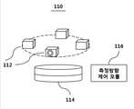
도 1, 도 2 및 도 3을 함께 참조하면, 본 발명의 일실시예에 따른 구조물 내부 점검 장치(100)는 구조물 내부의 상태를 측정하기 위하여, 상기 구조물 내부를 상하방향으로 이동하며 측정하는 3차원측정부(110); 상기 3차원측정부의 상기 구조물 내부에서의 상하방향 이동을 제어하고, 상기 3차원측정부의 측정 기준위치를 제어하는 위치제어부(120); 및 상기 3차원측정부로부터 측정 데이터 및 상기 위치제어부로부터 상기 3차원측정부의 측정 기준위치 데이터를 제공받아, 상기 구조물 내부의 형상을 분석하고, 상기 구조물 내부의 상태를 판단하는 3차원분석부(130);를 포함할 수 있다.Referring to Figures 1, 2 and 3 together, the structure inside the
상기 3차원측정부(110)는 구조물 내부를 상하방향으로 이동하며, 구조물 내부의 형상을 파악하기 위한 측정을 수행하는 것으로, 상기 3차원측정부(110)는 상기 구조물 내부의 영상을 촬영하기 위한 적어도 하나의 카메라(112); 상기 구조물 내부의 형상을 측정하기 위한 라이다(114, Lidar); 및 상기 라이다의 측정방향을 제어하기 위한 측정방향 제어 모듈(116);을 포함할 수 있다.The three-
상기 3차원측정부의 카메라(112)는 적어도 하나 구비되어 구조물 내부의 영상을 촬영하는 것일 수 있다. 영상 데이터를 이용하여 구조물 내부의 변형, 손상 여부를 파악할 수 있을 것이다.At least one
상기 카메라(112)는 개별 카메라의 화각을 고려하여 360도를 모두 커버할 수 있는 개수로 구성될 수 있다. 즉, 카메라의 화각이 120도를 커버할 수 있다면, 3개의 카메라를 이용하면 360도 전체를 커버할 수 있을 것이다. 한편, 상기 카메라(112)를 하나만 구성하면서 360도를 회전하는 구성을 부가하여 360도 전체를 커버하는 실시예도 가능할 것이다.The
상기 3차원 측정부의 라이다(114)는 구조물 내부의 형상을 측정하기 위한 것일 수 있다.The
일반적으로 라이다는 레이저를 발사하여 반사되는 레이저가 돌아오는 시간 등으로부터 측정 대상물의 거리와 형상 등 물리적 성질을 측정하는 장치이며, 레이더가 극초단파를 이용하여 대상물까지의 왕복 시간을 관측함으로써 거리를 구하는 것처럼, 라이다도 레이저를 이용하여 동일한 원리로 거리를 측정할 수 있다. 다만, 라이다는 측정 대상과의 거리가 너무 가깝거나 측정 대상에 레이저가 닿지 않는 음영구역이 있는 경우에는 정상적인 측정이 불가능한 한계를 가지게 된다.In general, a lidar is a device that measures the physical properties such as the distance and shape of a measurement object from the time when the laser is reflected by firing a laser, etc., and the radar calculates the distance by observing the round trip time to the object using microwaves. Likewise, a lidar can also measure distances using the same principle using a laser. However, the lidar has a limit in which normal measurement is impossible when the distance to the measurement object is too close or there is a shadow area where the laser does not reach the measurement object.
또한, 라이다는 내부에서 레이저를 송수신하는 모듈이 360도를 회전하면서 측정하는 특징을 가지고 있다. 이에 따라, 라이다는 내부 송수신 모듈의 회전 평면을 중심으로 거리를 측정하게 되며, 회전 평면의 약 상향 15도와 하향 15도에 해당하는 측정 범위를 가지게 된다.In addition, the rider has a feature that the module that transmits and receives the laser from the inside to measure while rotating 360 degrees. Accordingly, the lidar measures the distance around the rotation plane of the internal transmission and reception module, and has a measurement range corresponding to about 15 degrees upward and 15 degrees downward of the rotation plane.
도 4는 본 발명의 일실시예에 따른 구조물 내부 점검 장치의 3차원측정부에서 라이다의 동작을 설명하기 위한 도면이다. 도 5는 본 발명의 일실시예에 따른 구조물 내부 점검 장치의 3차원측정부에서 라이다의 측정방향 변화를 설명하기 위한 도면이다.4 is a view for explaining the operation of the lidar in the three-dimensional measuring unit of the inspection apparatus inside the structure according to an embodiment of the present invention. 5 is a view for explaining a change in the measurement direction of the lidar in the three-dimensional measurement unit of the structure inspection apparatus according to an embodiment of the present invention.
도 4(a)를 참조하면, 라이다의 회전 평면(또는 측정 방향)을 파란색 점선으로 나타내고 있고, 상하 약 15도의 각도를 빨간색 점선으로 나타내고 있다.Referring to Fig. 4A, the rotation plane (or measurement direction) of the lidar is indicated by a dotted blue line, and the angle of about 15 degrees up and down is indicated by a dotted red line.
도 4(b)를 참조하면, 라이다와 측정 대상과의 거리가 너무 가까운 경우에는 정상적인 거리를 측정할 수 없는 측정 거리 한계를 설명하고 있다. 즉, 라이다의 측정 거리 한계 이내의 공간이 있는 구간에서는 정상적인 구조물 내부와의 거리 측정이 불가능한 상황에 빠질 수 있다.Referring to FIG. 4 (b), the measurement distance limit where the normal distance cannot be measured when the distance between the lidar and the measurement object is too close is described. That is, in a section in which there is a space within the measurement distance limit of the lidar, it may be in a situation where the distance measurement with the inside of the structure is impossible.
이러한 측정 거리 한계 구간에서는 도 4(c)와 같이 라이다의 측정 방향을 변화하여 측정을 수행할 수 있을 것이다. 이것은 라이다의 거리 측정이 회전 평면 뿐만 아니라 상하 약 15도의 각도까지도 거리 측정이 가능한 특징을 이용하는 것이다.In this measurement distance limit section, the measurement direction of the lidar may be changed as shown in FIG. 4 (c). This is because the distance measurement of the lidar uses a feature that can measure not only the plane of rotation but also an angle of about 15 degrees up and down.
도 4(d)를 참조하면, 구조물이 비스듬하게 파여 있어 라이다가 가시영역에 들어오지 않는 음영구역(회색 표시)이 있는 경우에는 도 4(e)와 같이 측정방향 제어 모듈에 의해 라이다를 기울여서 음영구역도 측정 가능한 특징을 이용할 수 있다.Referring to FIG. 4 (d), when there is a shaded area (gray mark) where the structure is obliquely inserted and does not enter the visible area, the lidar is inclined by the measurement direction control module as shown in FIG. 4 (e). Shadow areas can also take advantage of measurable features.
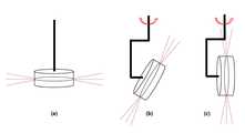
상기 3차원측정부(110)는 상기 라이다(114)의 측정방향을 수평방향과 평행하게 측정을 수행하며, 상기 구조물 내부에서 상기 라이다의 측정 거리 한계 또는 음영구역 원인으로 측정이 되지 않는 구간에 대하여는, 상기 측정방향 제어 모듈(116)을 이용하여, 상기 라이다의 측정방향을 수평방향과 미리 정해진 각도를 갖도록 변화시키고, 상기 라이다를 일정한 주기로 상기 측정 기준위치를 중심으로 회전시키면서 측정하는 것일 수 있다.The three-
도 5(c)를 참조하면, 상기 측정방향 제어 모듈(116)은 상기 라이다(114)의 측정방향을 수평방향과 직교하도록 변화시키는 것일 수 있다. 이경우 라이다의 측정 거리 한계를 가장 효율적으로 회피할 수 있을 것이다.Referring to FIG. 5C, the measurement
도 5(b)를 참조하면, 라이다(114)의 측정방향을 수평방향과 직교하지 않은 상태, 즉, 미리 정해진 각도를 갖도록 변화시킨 상태에서도 라이다와 구조물 내부 사이의 거리는 측정할 수 있을 것이다.Referring to FIG. 5B, the distance between the lidar and the inside of the structure may be measured even when the measurement direction of the
더불어, 라이다(114)의 측정방향을 수평방향과 직교하거나, 미리 정해진 각도를 갖도록 변화시킨 상태에서는 라이다(114)를 일정한 주기로 상기 측정 기준위치를 중심으로 회전시키는 구성이 추가적으로 필요할 것이다.In addition, in a state in which the measurement direction of the
도 1을 참조하면, 본 발명의 일실시예에 따른 구조물 내부 점검 장치(100)의 위치제어부(120)는 상기 3차원측정부(110)의 상기 구조물 내부에서의 상하방향 이동을 제어하고, 상기 3차원측정부(110)의 측정 기준위치를 제어하는 것일 수 있다.Referring to FIG. 1, the
상기 위치제어부(120)는 상기 3차원측정부(110)의 측정이 원활하게 수행될 수 있도록, 측정 기준위치를 미리 설정된 위치로 이동하도록 제어하거나 현재 위치를 측정 기준위치로 설정하여 3차원분석부(130)에서 정확한 분석이 수행될 수 있도록 측정 기준위치를 제공할 수 있다.The
더불어, 위치제어부(120)는 구조물 내부 전체를 점검할 수 있도록, 도 1 및 도 2와 같이, 연결 모듈(122)를 이용하여, 상기 3차원측정부(110)를 상하방향으로 이동시키는 것일 수 있다. 상기 3차원측정부(110)를 상하방향으로 이동시키면서 측정이 정상적으로 수행되는 구간 및 상기 라이다의 측정 거리 한계 원인으로 측정이 되지 않는 구간을 파악할 수 있을 것이다.In addition, the
상기 라이다의 측정 거리 한계 원인으로 측정이 되지 않는 구간에 대하여는 반복하여 측정을 할 수도 있으며, 해당 구간에 대하여는 상기 라이다의 측정방향을 변화시켜 측정을 수행할 수도 있을 것이다.The measurement may be repeated for a section that is not measured due to the measurement distance limit of the lidar, and the measurement may be performed by changing the measurement direction of the lidar.
또한, 상기 위치제어부(120)는 상기 3차원측정부(110)와 연결되는 적어도 하나의 케이블을 포함하며, 상기 적어도 하나의 케이블을 이용하여, 상기 3차원측정부와 통신을 수행하고, 전원을 공급하는 것일 수 있다.In addition, the
도 6은 본 발명의 일실시예에 따른 구조물 내부 점검 장치의 위치제어부의 반투명 패널을 설명하기 위한 도면이다.6 is a view for explaining a translucent panel of the position control unit of the structure inspection apparatus according to an embodiment of the present invention.
도 6을 참조하면, 본 발명의 일실시예에 따른 구조물 내부 점검 장치의 위치제어부(120)는 상기 3차원분석부(110)의 상부로 미리 정해진 거리 이격되고, 상기 3차원분석부(110)와 평행하게 구비되며, 광 투과가 가능한 반투명 패널(124);을 포함하는 것일 수 있으며, 상기 반투명 패널(124)에 미리 정해진 형상의 직진광을 전송하고, 상기 반투명 패널에 형성된 상기 직진광의 반사 형상을 이용하여 자세를 분석하는 것일 수 있다.Referring to FIG. 6, the
상기 3차원측정부(110)는 정확한 측정을 수행하기 위하여, 구조물 내부 공간에서 항상 수평을 유지해야 할 필요성이 있을 것이다. 도 6에서 반투명 패널(124)에 형성된 빨간색 사각형은 사각형 형상의 직진광을 전송한 결과에 따른 반사 형상일 수 있을 것이다. 결국, 상기 반투명 패널(124)에 형성된 빨간색 사각형을 이용하여 공간 내에서 수평을 유지하고 있는지 여부를 쉽게 파악할 수 있을 것이다.The three-
한편, 상기 반투명 패널(124)은 복수개의 광 반응 센서를 포함하며, 상기 광 반응 센서는, 상기 직진광의 도달 위치에 밀집되어 형성되는 것일 수 있으며, 이는 보다 선명한 직진광의 형상을 파악하기 위한 것일 수 있다.Meanwhile, the
한편, 상기 위치제어부(120)에서 상기 3차원측정부(110)의 자세를 분석한 결과, 상기 3차원측정부(110)가 일 측으로 기울어져 있다고 확인되는 경우, 상기 위치제어부(120)에서 제어를 수행하여 상기 3차원측정부(120)가 수평이 되도록 자세를 제어할 수 있을 것이다.On the other hand, as a result of analyzing the posture of the three-
도 7은 본 발명의 일실시예에 따른 구조물 내부 점검 장치의 3차원분석부를 설명하기 위한 블록도이다.7 is a block diagram illustrating a three-dimensional analysis unit of the structure inspection apparatus according to an embodiment of the present invention.
도 1 및 도 7을 함께 참조하면, 본 발명의 일 실시예에 따른 구조물 내부 점검 장치의 3차원분석부(130)는 상기 3차원측정부(110)로부터 측정 데이터 및 상기 위치제어부(120)로부터 상기 3차원측정부의 측정 기준위치 데이터를 제공받아, 상기 구조물 내부의 형상을 분석하고, 상기 구조물 내부의 상태를 판단하는 것일 수 있다.1 and 7 together, the three-
또한, 상기 3차원측정부(110)로부터 제공받는 측정 데이터는 상기 적어도 하나의 카메라 영상 데이터 및 상기 라이다의 형상 데이터를 포함하며, 상기 3차원분석부(130)는 상기 적어도 하나의 카메라 영상 데이터 및 상기 라이다의 형상 데이터를 결합하여 상기 구조물 내부의 형상을 분석하고, 상기 구조물 내부의 상태를 판단하는 것일 수 있다.In addition, the measurement data provided from the three-
즉, 적어도 하나의 카메라 영상 데이터, 상기 라이다를 이용하여 측정한 형상 데이터를 결합하여 구조물 내부의 형상을 분석하고, 위치 정보를 기준으로 구조물 내부 형상 결합을 위하여, 상기 위치제어부(120)로부터 상기 3차원측정부의 측정 기준위치 데이터를 제공받게 되는 것이다.That is, at least one camera image data and shape data measured using the lidar are combined to analyze the shape of the interior of the structure, and the
도 4 및 도 5를 함께 참조하면, 상기 3차원분석부(130)는 상기 측정방향 제어 모듈로부터 상기 라이다의 측정방향 변화 데이터 및 회전 데이터를 더 제공받아, 상기 구조물 내부의 형상을 분석하고, 상기 구조물 내부의 상태를 판단하는 것일 수 있다.4 and 5 together, the three-
즉, 라이다의 측정 거리 한계 및 음영구역 원인으로 측정이 되지 않는 구간에서는 상기 측정방향 제어 모듈(116)을 이용하여, 상기 라이다(114)의 측정방향을 수평방향과 미리 정해진 각도를 갖도록 변화시키고, 상기 라이다를 일정한 주기로 상기 측정 기준위치를 중심으로 회전시키면서 측정하게 되는데, 이 경우에 상기 3차원분석부(130)는 상기 측정방향 제어 모듈로부터 상기 라이다의 측정방향 변화 데이터 및 회전 데이터를 더 제공받아야만 보다 정확한 구조물 내부의 형상 분석 및 상기 구조물 내부의 상태를 판단할 수 있기 때문일 것이다.That is, in the section that cannot be measured due to the measurement distance limit and the shadow area of the lidar, the measurement direction of the
한편, 상기 3차원분석부(130)는 외력 또는 외부 에너지로 인한 돌발 상황이 발생하는 경우, 상기 3차원 분석부의 동작을 정지시키는 것일 수 있다. 이것은 외력 등에 의한 돌발 상황에서는 상기 3차원측정부의 기준 위치가 흔들릴 가능성이 있으며, 기기가 파손될 우려도 있으므로, 이러한 돌발 상황을 대비하기 위한 것이다.On the other hand, the three-
더불어, 상기 3차원분석부(130)는 저장 모듈(132)을 더 포함하고, 상기 3차원측정부로부터 측정 데이터 및 상기 위치제어부로부터 상기 3차원측정부의 측정 기준위치 데이터를 제공받아 상기 저장 모듈에 저장함과 동시에 외부 서버로 전송하는 것일 수 있다.In addition, the three-
본 발명의 일실시예에 따른 구조물 내부 점검 장치에서 상기 구조물은 노(furnace)이며, 상기 상태 분석은 상기 노 내부의 안전성 여부를 분석하는 것일 수 있다. 특히, 소화로 등의 경우에는 열에 의한 열화 등으로 노 내부가 손상되기 쉬우므로, 안전사고 예방을 위하여 노 내부를 정기적으로 점검할 수 있을 것이다.In the structure inspection apparatus according to an embodiment of the present invention, the structure is a furnace (furnace), the state analysis may be to analyze the safety of the interior of the furnace. In particular, in the case of a fire extinguishing furnace, since the inside of the furnace is easily damaged by deterioration due to heat, the inside of the furnace may be periodically checked to prevent safety accidents.
이상 첨부된 도면을 참조하여 본 발명의 실시예를 설명하였지만, 본 발명이 속하는 기술분야에서 통상의 지식을 가진 자는 본 발명이 그 기술적 사상이나 필수적인 특징을 변경하지 않고서 다른 구체적인 형태로 실시될 수 있다는 것을 이해할 수 있을 것이다. 예를 들어 당업자는 각 구성요소의 재질, 크기 등을 적용 분야에 따라 변경하거나, 개시된 실시형태들을 조합 또는 치환하여 본 발명의 실시예에 명확하게 개시되지 않은 형태로 실시할 수 있으나, 이 역시 본 발명의 범위를 벗어나지 않는 것이다. 그러므로 이상에서 기술한 실시예들은 모든 면에서 예시적인 것으로 한정적인 것으로 이해해서는 안 되며, 이러한 변형된 실시예들은 본 발명의 특허청구범위에 기재된 기술사상에 포함된다고 하여야 할 것이다.Although embodiments of the present invention have been described above with reference to the accompanying drawings, those skilled in the art to which the present invention pertains may implement the present invention in other specific forms without changing the technical spirit or essential features thereof. I can understand that. For example, those skilled in the art can change the material, size, etc. of each component according to the application field, or combine or replace the disclosed embodiments in a form that is not clearly disclosed in the embodiments of the present invention, but this also It does not depart from the scope of the invention. Therefore, the above-described embodiments are to be considered in all respects as illustrative and not restrictive, and such modified embodiments should be included in the technical spirit described in the claims of the present invention.
100: 구조물 내부 점검 장치
110: 3차원측정부112: 카메라
114: 라이다116: 측정방향 제어 모듈
120: 위치제어부122: 연결 모듈
124: 반투명 패널130: 3차원분석부
132: 저장 모듈100: structure inspection device
110: three-dimensional measuring unit 112: camera
114: lidar 116: measuring direction control module
120: position control unit 122: connection module
124: translucent panel 130: three-dimensional analysis unit
132: storage module
Claims (12)
Translated fromKorean상기 3차원측정부의 상기 구조물 내부에서의 상하방향 이동을 제어하고, 상기 3차원측정부의 측정 기준위치를 제어하는 위치제어부; 및
상기 3차원측정부로부터 측정 데이터 및 상기 위치제어부로부터 상기 3차원측정부의 측정 기준위치 데이터를 제공받아, 상기 구조물 내부의 형상을 분석하고, 상기 구조물 내부의 상태를 판단하는 3차원분석부;
를 포함하며,
상기 3차원측정부는
상기 구조물 내부의 영상을 촬영하기 위한 적어도 하나의 카메라;
상기 구조물 내부의 형상을 측정하기 위한 라이다(Lidar); 및
상기 라이다의 측정방향을 제어하기 위한 측정방향 제어 모듈;
을 포함하고,
상기 3차원측정부는
상기 라이다의 측정방향을 수평방향과 평행하게 측정을 수행하며,
상기 구조물 내부에서 상기 라이다의 측정 거리 한계 또는 음영구역 원인으로 측정이 되지 않는 구간에 대하여는,
상기 측정방향 제어 모듈을 이용하여, 상기 라이다의 측정방향을 수평방향과 미리 정해진 각도를 갖도록 변화시키고, 상기 라이다를 일정한 주기로 상기 측정 기준위치를 중심으로 회전시키면서 측정하며,
상기 위치제어부는
상기 3차원측정부와 연결되는 적어도 하나의 케이블을 포함하며, 상기 적어도 하나의 케이블을 이용하여, 상기 3차원측정부와 통신을 수행하고, 전원을 공급하며,
상기 위치제어부는
상기 3차원분석부의 상부로 미리 정해진 거리 이격되고, 상기 3차원분석부와 평행하게 구비되며, 광 투과가 가능한 반투명 패널;을 포함하며,
상기 반투명 패널에 미리 정해진 형상의 직진광을 전송하고, 상기 반투명 패널에 형성된 상기 직진광의 반사 형상을 이용하여 자세를 분석하는 것을 특징으로 하는 구조물 내부 점검 장치.In order to measure the state of the inside of the structure, the three-dimensional measuring unit for measuring the inside of the structure moving in the vertical direction;
A position control unit for controlling a vertical movement of the three-dimensional measurement unit inside the structure and controlling a measurement reference position of the three-dimensional measurement unit; And
A three-dimensional analyzer receiving measurement data from the three-dimensional measuring unit and measurement reference position data of the three-dimensional measuring unit from the position control unit, analyzing a shape inside the structure and determining a state inside the structure;
Including;
The three-dimensional measuring unit
At least one camera for capturing an image inside the structure;
Lidar for measuring the shape of the inside of the structure (Lidar); And
A measurement direction control module for controlling the measurement direction of the lidar;
Including,
The three-dimensional measuring unit
The measurement direction of the lidar is performed parallel to the horizontal direction,
For the section that is not measured due to the measurement distance limit or the shadow area of the lidar inside the structure,
By using the measuring direction control module, the measuring direction of the lidar is changed to have a predetermined angle with a horizontal direction, and the lidar is measured while rotating about the measuring reference position at regular intervals,
The position control unit
At least one cable connected to the three-dimensional measuring unit, using the at least one cable, performs communication with the three-dimensional measuring unit, and supplies power,
The position control unit
And a translucent panel spaced apart from a predetermined distance to an upper portion of the three-dimensional analysis unit and provided in parallel with the three-dimensional analysis unit and capable of transmitting light.
And transmitting a straight light having a predetermined shape to the translucent panel, and analyzing a posture by using a reflected shape of the straight light formed on the translucent panel.
상기 3차원분석부는
상기 측정방향 제어 모듈로부터 상기 라이다의 측정방향 변화 데이터 및 회전 데이터를 더 제공받아,
상기 구조물 내부의 형상을 분석하고, 상기 구조물 내부의 상태를 판단하는 것을 특징으로 하는 구조물 내부 점검 장치.The method of claim 1,
The three-dimensional analysis unit
Further receiving the measurement direction change data and rotation data of the lidar from the measurement direction control module,
Analyze the shape inside the structure, and determine the internal structure of the structure, characterized in that for determining the state inside the structure.
상기 측정방향 제어 모듈은,
상기 라이다의 측정방향을 수평방향과 직교하도록 변화시키는 것을 특징으로 하는 구조물 내부 점검 장치.The method of claim 1,
The measuring direction control module,
And the measuring direction of the lidar is changed to be orthogonal to the horizontal direction.
상기 3차원측정부로부터 제공받는 측정 데이터는 상기 적어도 하나의 카메라 영상 데이터 및 상기 라이다의 형상 데이터를 포함하며,
상기 3차원분석부는 상기 적어도 하나의 카메라 영상 데이터 및 상기 라이다의 형상 데이터를 결합하여 상기 구조물 내부의 형상을 분석하고, 상기 구조물 내부의 상태를 판단하는 것을 특징으로 하는 구조물 내부 점검 장치.The method of claim 1,
The measurement data provided from the 3D measurement unit includes the at least one camera image data and the shape data of the lidar,
The three-dimensional analysis unit combines the at least one camera image data and the shape data of the lidar to analyze the shape inside the structure, and determine the state inside the structure.
상기 반투명 패널은,
복수개의 광 반응 센서를 포함하며, 상기 광 반응 센서는, 상기 직진광의 도달 위치에 밀집되어 형성되는 것을 특징으로 하는 구조물 내부 점검 장치.The method of claim 1,
The translucent panel,
And a plurality of photoreaction sensors, wherein the photoresponse sensors are densely formed at the arrival position of the straight light.
상기 3차원분석부는
외력 또는 외부 에너지로 인한 돌발 상황이 발생하는 경우, 상기 3차원 분석부의 동작을 정지시키는 것을 특징으로 하는 구조물 내부 점검 장치.The method of claim 1,
The three-dimensional analysis unit
When the sudden situation occurs due to external force or external energy, the internal structure inspection apparatus, characterized in that to stop the operation of the three-dimensional analysis unit.
상기 3차원분석부는 저장 모듈을 더 포함하고,
상기 3차원측정부로부터 측정 데이터 및 상기 위치제어부로부터 상기 3차원측정부의 측정 기준위치 데이터를 제공받아 상기 저장 모듈에 저장함과 동시에 외부 서버로 전송하는 것을 특징으로 하는 구조물 내부 점검 장치.The method of claim 1,
The three-dimensional analysis unit further comprises a storage module,
And receiving the measurement data from the three-dimensional measuring unit and the measurement reference position data of the three-dimensional measuring unit from the position control unit, storing the stored data in the storage module and transmitting the same to an external server.
상기 구조물은 노(furnace)이며, 상기 상태 분석은 상기 노 내부의 안전성 여부를 분석하는 것을 특징으로 하는 구조물 내부 점검 장치.
The method of claim 1,
The structure is a furnace (furnace), the condition analysis device inside the structure, characterized in that for analyzing the safety of the interior of the furnace.
Priority Applications (1)
| Application Number | Priority Date | Filing Date | Title |
|---|---|---|---|
| KR1020180073352AKR102022964B1 (en) | 2018-06-26 | 2018-06-26 | Apparatus for inspecting the inside of a structure |
Applications Claiming Priority (1)
| Application Number | Priority Date | Filing Date | Title |
|---|---|---|---|
| KR1020180073352AKR102022964B1 (en) | 2018-06-26 | 2018-06-26 | Apparatus for inspecting the inside of a structure |
Publications (1)
| Publication Number | Publication Date |
|---|---|
| KR102022964B1true KR102022964B1 (en) | 2019-09-19 |
Family
ID=68067752
Family Applications (1)
| Application Number | Title | Priority Date | Filing Date |
|---|---|---|---|
| KR1020180073352AActiveKR102022964B1 (en) | 2018-06-26 | 2018-06-26 | Apparatus for inspecting the inside of a structure |
Country Status (1)
| Country | Link |
|---|---|
| KR (1) | KR102022964B1 (en) |
Citations (9)
| Publication number | Priority date | Publication date | Assignee | Title |
|---|---|---|---|---|
| JP2002107128A (en)* | 2000-10-02 | 2002-04-10 | Sanyo Electric Co Ltd | Shape-measuring apparatus |
| JP2005170258A (en)* | 2003-12-11 | 2005-06-30 | Hideaki Saito | Vehicle-mounted monitoring camera system |
| JP2008286772A (en)* | 2007-05-21 | 2008-11-27 | Nippon System Kenkyusho:Kk | Attitude recognition sensor |
| KR20100053570A (en) | 2007-07-23 | 2010-05-20 | 콴텀스피어, 인크. | Compositions of nanometal particles |
| KR20120134414A (en)* | 2011-06-02 | 2012-12-12 | 이태경 | Intraoral bone anchored marker for the synchronization of three dimensional image data |
| KR20140079556A (en)* | 2012-12-15 | 2014-06-27 | 주식회사 디오에프연구소 | An auxiliary scan table for scanning 3D articulator dental model |
| KR101449931B1 (en)* | 2013-11-27 | 2014-10-15 | 이대봉 | Lidar apparatus for three-dimensional space scanner |
| JP2015129746A (en)* | 2013-12-17 | 2015-07-16 | ゼネラル・エレクトリック・カンパニイ | Method and device for automatically identifying the deepest point on an abnormal surface |
| KR20170074519A (en)* | 2015-12-22 | 2017-06-30 | 대우조선해양 주식회사 | Apparatus and method for inspecting of lng tank |
- 2018
- 2018-06-26KRKR1020180073352Apatent/KR102022964B1/enactiveActive
Patent Citations (9)
| Publication number | Priority date | Publication date | Assignee | Title |
|---|---|---|---|---|
| JP2002107128A (en)* | 2000-10-02 | 2002-04-10 | Sanyo Electric Co Ltd | Shape-measuring apparatus |
| JP2005170258A (en)* | 2003-12-11 | 2005-06-30 | Hideaki Saito | Vehicle-mounted monitoring camera system |
| JP2008286772A (en)* | 2007-05-21 | 2008-11-27 | Nippon System Kenkyusho:Kk | Attitude recognition sensor |
| KR20100053570A (en) | 2007-07-23 | 2010-05-20 | 콴텀스피어, 인크. | Compositions of nanometal particles |
| KR20120134414A (en)* | 2011-06-02 | 2012-12-12 | 이태경 | Intraoral bone anchored marker for the synchronization of three dimensional image data |
| KR20140079556A (en)* | 2012-12-15 | 2014-06-27 | 주식회사 디오에프연구소 | An auxiliary scan table for scanning 3D articulator dental model |
| KR101449931B1 (en)* | 2013-11-27 | 2014-10-15 | 이대봉 | Lidar apparatus for three-dimensional space scanner |
| JP2015129746A (en)* | 2013-12-17 | 2015-07-16 | ゼネラル・エレクトリック・カンパニイ | Method and device for automatically identifying the deepest point on an abnormal surface |
| KR20170074519A (en)* | 2015-12-22 | 2017-06-30 | 대우조선해양 주식회사 | Apparatus and method for inspecting of lng tank |
Similar Documents
| Publication | Publication Date | Title |
|---|---|---|
| JP6634314B2 (en) | Facility inspection system using unmanned aerial vehicles | |
| JP4889913B2 (en) | Infrared camera sensitive to infrared rays | |
| JP6166280B2 (en) | Piping inspection robot and piping inspection method | |
| KR101007984B1 (en) | Horizontal and vertical vibration and deflection measurement system and method of transmission line | |
| JP2019036269A (en) | Flight control method of pilotless small flying object, and inspection method of condition of internal space and condition of wall surface thereof | |
| US20190063907A1 (en) | Measurement system having a cooperative robot and three-dimensional imager | |
| JP7360983B2 (en) | Data acquisition device and method | |
| KR20170036488A (en) | Boiler tube diagnosis apparatus | |
| JP2010538947A (en) | Crane tong position control apparatus and method according to slab bending | |
| KR20160142482A (en) | Unmanned aerial vehicle system for a contruction site with a unmanned aerial vehicle unit and unmanned aerial vehicle server | |
| TW201703181A (en) | Substrate detection apparatus, substrate detection method and substrate processing system | |
| KR20240004127A (en) | Safety management method based on a structural safety management system using unmanned aerial vehicles and measuring devices | |
| JP2019144040A (en) | Object monitoring device using sensor | |
| WO2017168154A1 (en) | Remote temperature monitoring | |
| JP6200441B2 (en) | Reactor light-based fuel alignment system and method | |
| KR102022964B1 (en) | Apparatus for inspecting the inside of a structure | |
| EP3428897A1 (en) | Optical flame detector | |
| KR102584931B1 (en) | Drone for Structure Maintenance | |
| KR20170074519A (en) | Apparatus and method for inspecting of lng tank | |
| JP6311039B1 (en) | Fire detecting method for laser beam machine and laser beam machine | |
| IT202000018511A1 (en) | INSPECTION EQUIPMENT AND RELATED METHOD | |
| KR101029751B1 (en) | Structure displacement measuring system and method | |
| CN105666489A (en) | Manipulator used for correcting offline training data and method | |
| KR102747750B1 (en) | Wafer type sensing apparatus and substrate treating apparatus including the same | |
| JPH11287651A (en) | Indoor positioning device |
Legal Events
| Date | Code | Title | Description |
|---|---|---|---|
| PA0109 | Patent application | St.27 status event code:A-0-1-A10-A12-nap-PA0109 | |
| PA0201 | Request for examination | St.27 status event code:A-1-2-D10-D11-exm-PA0201 | |
| D13-X000 | Search requested | St.27 status event code:A-1-2-D10-D13-srh-X000 | |
| D14-X000 | Search report completed | St.27 status event code:A-1-2-D10-D14-srh-X000 | |
| PE0902 | Notice of grounds for rejection | St.27 status event code:A-1-2-D10-D21-exm-PE0902 | |
| E13-X000 | Pre-grant limitation requested | St.27 status event code:A-2-3-E10-E13-lim-X000 | |
| P11-X000 | Amendment of application requested | St.27 status event code:A-2-2-P10-P11-nap-X000 | |
| P13-X000 | Application amended | St.27 status event code:A-2-2-P10-P13-nap-X000 | |
| E701 | Decision to grant or registration of patent right | ||
| PE0701 | Decision of registration | St.27 status event code:A-1-2-D10-D22-exm-PE0701 | |
| GRNT | Written decision to grant | ||
| PR0701 | Registration of establishment | St.27 status event code:A-2-4-F10-F11-exm-PR0701 | |
| PR1002 | Payment of registration fee | St.27 status event code:A-2-2-U10-U11-oth-PR1002 Fee payment year number:1 | |
| PG1601 | Publication of registration | St.27 status event code:A-4-4-Q10-Q13-nap-PG1601 | |
| R18-X000 | Changes to party contact information recorded | St.27 status event code:A-5-5-R10-R18-oth-X000 | |
| S20-X000 | Security interest recorded | St.27 status event code:A-4-4-S10-S20-lic-X000 | |
| PR1001 | Payment of annual fee | St.27 status event code:A-4-4-U10-U11-oth-PR1001 Fee payment year number:4 | |
| PR1001 | Payment of annual fee | St.27 status event code:A-4-4-U10-U11-oth-PR1001 Fee payment year number:5 | |
| PR1001 | Payment of annual fee | St.27 status event code:A-4-4-U10-U11-oth-PR1001 Fee payment year number:6 | |
| R18-X000 | Changes to party contact information recorded | St.27 status event code:A-5-5-R10-R18-oth-X000 | |
| PR1001 | Payment of annual fee | St.27 status event code:A-4-4-U10-U11-oth-PR1001 Fee payment year number:7 |