KR102022005B1 - Brushless motor apparatus provided with improved assembly structure between insulation holder and electric terminal - Google Patents
Brushless motor apparatus provided with improved assembly structure between insulation holder and electric terminalDownload PDFInfo
- Publication number
- KR102022005B1 KR102022005B1KR1020180084672AKR20180084672AKR102022005B1KR 102022005 B1KR102022005 B1KR 102022005B1KR 1020180084672 AKR1020180084672 AKR 1020180084672AKR 20180084672 AKR20180084672 AKR 20180084672AKR 102022005 B1KR102022005 B1KR 102022005B1
- Authority
- KR
- South Korea
- Prior art keywords
- support
- support part
- insulating holder
- electrical terminal
- magnetic field
- Prior art date
- Legal status (The legal status is an assumption and is not a legal conclusion. Google has not performed a legal analysis and makes no representation as to the accuracy of the status listed.)
- Active
Links
- 230000001976improved effectEffects0.000titleclaimsabstractdescription12
- 238000009413insulationMethods0.000titledescription6
- 230000000149penetrating effectEffects0.000claimsabstractdescription3
- 238000000034methodMethods0.000claimsdescription10
- 238000004804windingMethods0.000description8
- 230000008569processEffects0.000description6
- 229910000975Carbon steelInorganic materials0.000description3
- 239000010962carbon steelSubstances0.000description3
- 230000008878couplingEffects0.000description2
- 238000010168coupling processMethods0.000description2
- 238000005859coupling reactionMethods0.000description2
- 230000000694effectsEffects0.000description2
- 238000007789sealingMethods0.000description2
- 229910000838Al alloyInorganic materials0.000description1
- RYGMFSIKBFXOCR-UHFFFAOYSA-NCopperChemical compound[Cu]RYGMFSIKBFXOCR-UHFFFAOYSA-N0.000description1
- XAGFODPZIPBFFR-UHFFFAOYSA-NaluminiumChemical compound[Al]XAGFODPZIPBFFR-UHFFFAOYSA-N0.000description1
- 229910052782aluminiumInorganic materials0.000description1
- 238000005452bendingMethods0.000description1
- 230000008901benefitEffects0.000description1
- 230000008859changeEffects0.000description1
- 239000004020conductorSubstances0.000description1
- 238000001816coolingMethods0.000description1
- 229910052802copperInorganic materials0.000description1
- 239000010949copperSubstances0.000description1
- 238000004512die castingMethods0.000description1
- 230000005611electricityEffects0.000description1
- 238000002347injectionMethods0.000description1
- 239000007924injectionSubstances0.000description1
- 238000001746injection mouldingMethods0.000description1
- 239000000463materialSubstances0.000description1
- 230000002265preventionEffects0.000description1
- XLYOFNOQVPJJNP-UHFFFAOYSA-NwaterSubstancesOXLYOFNOQVPJJNP-UHFFFAOYSA-N0.000description1
Images


Classifications
- H—ELECTRICITY
- H02—GENERATION; CONVERSION OR DISTRIBUTION OF ELECTRIC POWER
- H02K—DYNAMO-ELECTRIC MACHINES
- H02K5/00—Casings; Enclosures; Supports
- H02K5/04—Casings or enclosures characterised by the shape, form or construction thereof
- H02K5/22—Auxiliary parts of casings not covered by groups H02K5/06-H02K5/20, e.g. shaped to form connection boxes or terminal boxes
- H02K5/225—Terminal boxes or connection arrangements
- H—ELECTRICITY
- H02—GENERATION; CONVERSION OR DISTRIBUTION OF ELECTRIC POWER
- H02K—DYNAMO-ELECTRIC MACHINES
- H02K29/00—Motors or generators having non-mechanical commutating devices, e.g. discharge tubes or semiconductor devices
Landscapes
- Engineering & Computer Science (AREA)
- Power Engineering (AREA)
- Insulation, Fastening Of Motor, Generator Windings (AREA)
Abstract
Translated fromKoreanDescription
Translated fromKorean본 발명은 브러시리스 모터 장치에 관한 것으로서, 더 구체적으로는 브러시리스 모터 장치의 고정자를 구성하는 자계부의 코어를 수용하는 절연 홀더와 전기 터미널의 조립 구조에 관한 것이다.BACKGROUND OF THE INVENTION 1. Field of the Invention The present invention relates to a brushless motor device, and more particularly, to an assembly structure of an electrical terminal and an insulating holder for accommodating a core of a magnetic field constituting a stator of a brushless motor device.
일반적으로 모터는 전기 에너지를 기계적 에너지로 변환하는 장치이다. 모터는 가정용 전자제품뿐만 아니라 산업용 기기 등에 광범위하게 사용된다. 모터는 크게 직류 모터(DC motor)와 교류 모터(AC motor)로 구분한다. 직류 모터는 브러시(brush)에 의해 정류자에 전원을 공급하여 회전자를 회전시키는 형태와, 브러시를 사용하지 않는 브러시리스 형태의 모터가 있다.In general, a motor is a device that converts electrical energy into mechanical energy. Motors are widely used in household appliances as well as industrial equipment. Motors are largely divided into a DC motor and an AC motor. DC motors include a type of rotating a rotor by supplying power to a commutator by a brush and a brushless type of motor that does not use a brush.
최근에는 이러한 브러시리스 모터가 자동차의 팬 모터에도 적용되고 있다. 브러시리스 모터는 브러시가 있는 구조의 모터에 비하여 출력이 큰 장점이 있어서 대용량 팬이 적용되는 최근의 차량의 냉각용 모터로 사용되는 경향이 증가하는 추세이다. 이러한 브러시리스 모터의 일 예가 대한민국 공개특허 제2002-0066674호에 개시되어 있다.Recently, such a brushless motor has been applied to a fan motor of an automobile. Brushless motors have an advantage of greater output than motors having a brushed structure, and thus the trend of being used as a motor for cooling a vehicle of a large capacity fan is increasing. An example of such a brushless motor is disclosed in Korean Patent Laid-Open Publication No. 2002-0066674.
일반적으로 브러시리스 모터는 고정자와 회전자를 포함한다. 브러시리스 모터의 회전자는 영구자석을 포함한다. 브러시리스 모터의 고정자는 자기력을 발생시키는 코어와 권선 코일을 포함하는 자계부와 상기 권선 코일에 전기를 공급하는 제어부를 포함한다. 제어부는 통상적으로 인쇄회로기판 형태로 구성된다. 제어부에는 미세한 직류 전류가 흐르기 때문에 수분 등이 유입될 경우 치명적인 손상을 입게 된다. 따라서 브러시리스 모터는 자계부와 제어부를 연결하는 터미널을 통해 수분이 제어부로 유입되지 않도록 제어부를 구성하는 인쇄회로기판은 자계부와 독립적으로 제조되는 고정자 하우징 내부에 설치된다. 상기 고정자 하우징은 커버에 의해 외부에서 수분이 유입되지 않도록 밀봉된다.Brushless motors generally include stators and rotors. The rotor of the brushless motor includes a permanent magnet. The stator of the brushless motor includes a magnetic field unit including a core generating a magnetic force and a winding coil, and a control unit supplying electricity to the winding coil. The control unit is typically configured in the form of a printed circuit board. Since a minute DC current flows in the control unit, a fatal damage is caused when water or the like is introduced. Therefore, the brushless motor is a printed circuit board constituting the control unit is installed inside the stator housing is manufactured independently of the magnetic field unit so that moisture does not flow into the control unit through a terminal connecting the magnetic field unit and the control unit. The stator housing is sealed by a cover so that moisture does not flow in from the outside.
자계부는 다수의 절판을 절단하여 적층한 상태로 이루어진 코어와, 상기 코어를 수용하는 절연 홀더, 상기 절연 홀더에 권선된 코일 및 상기 코일의 일단부에 전기적으로 연결된 전기 터미널을 포함한다.The magnetic field unit includes a core formed by cutting a plurality of cutouts and being laminated, an insulation holder accommodating the core, a coil wound around the insulation holder, and an electrical terminal electrically connected to one end of the coil.
상기 전기 터미널은 먼저 절연 홀더에 조립된 후 상기 코일을 코어에 권선한 후 상기 전기 터미널에 전기적으로 연결된다. 통상적으로 상기 전기 터미널은 상기 코일이 복수회 권선될 때 코일이 걸리는 코일 고정부를 포함한다.The electrical terminal is first assembled in an insulated holder and then the coil is wound around the core and then electrically connected to the electrical terminal. Typically the electrical terminal comprises a coil fixture on which the coil is caught when the coil is wound a plurality of times.
그런데 상기 코일 조정부에는 코일이 권선 되는 과정에서 코일의 장력에 의해 힘이 가해진다. 이 경우에 종래 구조에서는 코일의 권선 과정에서 상기 전기 터미널의 고정 위치가 변경되어 후속적인 제어부와 전기 터미널을 연결하는 공정이 원만하게 진행되지 못하는 문제점이 있다.However, a force is applied to the coil adjusting unit by the tension of the coil in the process of winding the coil. In this case, in the conventional structure, the fixing position of the electrical terminal is changed during the winding of the coil, so that a process of connecting the subsequent control unit and the electrical terminal does not proceed smoothly.
본 발명의 목적은 상술한 바와 같은 문제점을 해소하기 위해 안출된 것으로서, 전기 터미널과 절연 홀더의 조립 구조를 개선함으로써 코일이 권선 되는 과정에서 전기 터미널의 위치가 변동되지 않도록 하여 브러시리스 모터 장치의 조립시간을 단축시키고, 조립성을 향상시키며, 전기 터미널의 조립치수 관리가 불필요한 브러시리스 모터 장치를 제공하는 데 있다.An object of the present invention is to solve the problems described above, the assembly structure of the electrical terminal and the insulating holder by improving the assembly structure of the brushless motor device so that the position of the electrical terminal does not change in the process of winding the coil The present invention provides a brushless motor device that reduces time, improves assembly, and eliminates assembly dimension management of an electrical terminal.
상기 목적을 달성하기 위해 본 발명의 일 실시 예에 따른 절연 홀더와 전기 터미널의 조립 구조가 개선된 브러시리스 모터 장치는, 고정자 하우징 내부에 인쇄회로기판 형태로 설치된 제어부;
상기 고정자 하우징의 외부에 배치되며 상기 고정자 하우징에 고정된 자계부; 및
상기 자계부와 상기 제어부를 전기적으로 연결하는 전기 터미널을 포함하는 브러리시스 모터 장치에 있어서,
상기 전기 터미널은, 몸체;
상기 몸체에서 기둥 형태로 연장되어 상기 제어부에 전기적으로 연결되는 제1연결핀;
상기 몸체로부터 상기 제1연결핀과 수직인 방향으로 연장되며 상기 자계부와 결합된 절연 홀더에 접촉 지지되는 제1지지부;
상기 제1지지부의 단부로부터 상기 제1연결핀과 반대 방향으로 연장되어 상기 절연 홀더를 관통하는 제2연결핀; 및
상기 몸체로부터 상기 제1지지부와 반대 방향으로 연장되며 상기 절연 홀더에 접촉 지지되며 상기 제1지지부를 기준으로 상기 제1지지부의 양측에 배치된 한 쌍의 제2지지부;를 포함하며,
상기 절연 홀더는 상기 제1지지부 및 상기 제2지지부와 접촉지지되도록 상기 절연 홀더의 하면으로부터 외측으로 돌출된 돌출 지지부를 포함한 점에 특징이 있다.In order to achieve the above object, a brushless motor device having an improved assembly structure of an insulating holder and an electrical terminal according to an embodiment of the present invention includes a control unit installed in a stator housing in the form of a printed circuit board;
A magnetic field unit disposed outside the stator housing and fixed to the stator housing; And
In the brushless motor device comprising an electrical terminal for electrically connecting the magnetic field unit and the control unit,
The electrical terminal includes a body;
A first connection pin extending from the body in the form of a column and electrically connected to the controller;
A first support part extending from the body in a direction perpendicular to the first connecting pin and supported by an insulating holder coupled to the magnetic field part;
A second connecting pin extending from an end of the first support part in a direction opposite to the first connecting pin and penetrating the insulating holder; And
And a pair of second support parts extending from the body in the opposite direction to the first support part and supported by the insulating holder and disposed on both sides of the first support part with respect to the first support part.
The insulating holder is characterized in that it comprises a protruding support protruding outward from the lower surface of the insulating holder to be in contact with the first support and the second support.
삭제delete
삭제delete
삭제delete
삭제delete
삭제delete
삭제delete
삭제delete
삭제delete
상기 제2지지부의 단부가 절곡(bending)되어 상기 제1연결핀으로부터 점점 더 멀어지는 방향으로 연장된 코일 걸림부를 포함한 것이 바람직하다.Preferably, the end portion of the second support portion is bent and includes a coil catching portion extending in a direction further away from the first connecting pin.
상기 몸체의 양단부로부터 상기 제1연결핀의 반대 방향으로 연장되며 자유단부가 상기 제1연결핀 및 상기 제1지지부와 수직인 방향으로 절곡되어 상기 절연 홀더에 접촉 지지되는 제3지지부;를 포함한 것이 바람직하다.And a third support part extending from opposite ends of the body in the opposite direction to the first connection pin and having a free end bent in a direction perpendicular to the first connection pin and the first support part to be in contact with and supported by the insulating holder. desirable.
상기 돌출 지지부로부터 기둥 형태로 형성된 고정 돌기를 포함하며,It includes a fixing protrusion formed in the form of a column from the projecting support,
상기 고정 돌기는 상기 제1지지부에 형성된 고정공에 결합된 것이 바람직하다.The fixing protrusion is preferably coupled to the fixing hole formed in the first support portion.
상기 돌출 지지부의 양측에 배치되며 상기 제3지지부의 단부가 수용되도록 계곡 형태로 형성되며 일측면이 개방된 홈부인 측면 유동 방지홈;을 포함한 것이 바람직하다.And side flow preventing grooves disposed on both sides of the protruding support part and formed in a valley shape to accommodate the end of the third support part and having one side of the open groove part.
본 발명에 따른 절연 홀더와 전기 터미널의 조립 구조가 개선된 브러시리스 모터 장치는, 전기 터미널이 절연 홀더에 조립된 상태에서 코어에 코일이 권선될 경우 권선 되는 코일의 장력이 작용하더라도 전기 터미널이 각각 다른 방향으로 형성되며 상기 절연 홀더에 접촉 지지된 제1지지부, 제2지지부 및 제3지지부에 의해 견고하제 지지됨으로써 전기 터미널의 위치가 변경되지 않도록 하여 조립 시간을 단축할 뿐 아니라 조립성이 향상되는 효과를 제공한다.In the brushless motor device having an improved assembly structure of the insulating holder and the electric terminal according to the present invention, even if the coil is wound on the core while the electric terminal is assembled to the insulating holder, the electric terminals are respectively wound. It is formed in the other direction and is firmly supported by the first support part, the second support part and the third support part which are in contact with and supported by the insulating holder, so that the position of the electric terminal is not changed, thereby reducing assembly time and improving assembly performance. Provide effect.
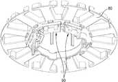
도 1은 본 발명의 바람직한 실시 예에 따른 브러시리스 모터 장치의 사시도이다.
도 2는 도 1에 도시된 브러시리스 모터 장치의 분리 사시도이다.
도 3은 도 1에 도시된 절연 홀더와 전기 터미널의 결합 구조를 보여주는 도면이다.
도 4는 도 3에 도시된 구조를 다른 방향에서 본 도면이다.
도 5는 도 3에 도시된 전기 터미널의 구조를 보여주는 도면이다.
도 6은 도 3에 도시된 절연 홀더의 돌출 지지부 구조를 보여주는 도면이다.
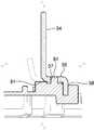
도 7은 도 4에 도시된 Ⅶ - Ⅶ 선 단면도이다.
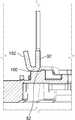
도 8은 도 4에 도시된 Ⅷ - Ⅷ 선 단면도이다.
도 9는 도 4에 도시된 Ⅸ - Ⅸ 선 단면도이다.1 is a perspective view of a brushless motor apparatus according to a preferred embodiment of the present invention.
FIG. 2 is an exploded perspective view of the brushless motor device shown in FIG. 1. FIG.
FIG. 3 is a view illustrating a coupling structure of the insulating holder and the electrical terminal illustrated in FIG. 1.
4 is a view of the structure shown in FIG. 3 viewed from another direction.
5 is a view showing the structure of the electrical terminal shown in FIG.
FIG. 6 is a view illustrating a structure of a protrusion support of the insulating holder illustrated in FIG. 3.
FIG. 7 is a sectional view taken along line VIII-VIII in FIG. 4.
FIG. 8 is a sectional view taken along line VIII-VIII in FIG. 4.
FIG. 9 is a sectional view taken along line VIII-VIII in FIG. 4. FIG.
이하, 본 발명에 따른 바람직한 일 실시 예를 첨부된 도면을 참조하면서 상세히 설명하기로 한다.Hereinafter, exemplary embodiments of the present invention will be described in detail with reference to the accompanying drawings.
도 1은 본 발명의 바람직한 실시 예에 따른 브러시리스 모터 장치의 사시도이다. 도 2는 도 1에 도시된 브러시리스 모터 장치의 분리 사시도이다. 도 3은 도 1에 도시된 절연 홀더와 전기 터미널의 결합 구조를 보여주는 도면이다. 도 4는 도 3에 도시된 구조를 다른 방향에서 본 도면이다. 도 5는 도 3에 도시된 전기 터미널의 구조를 보여주는 도면이다. 도 6은 도 3에 도시된 절연 홀더의 돌출 지지부 구조를 보여주는 도면이다. 도 7은 도 4에 도시된 Ⅶ - Ⅶ 선 단면도이다. 도 8은 도 4에 도시된 Ⅷ - Ⅷ 선 단면도이다. 도 9는 도 4에 도시된 Ⅸ - Ⅸ 선 단면도이다.1 is a perspective view of a brushless motor apparatus according to a preferred embodiment of the present invention. FIG. 2 is an exploded perspective view of the brushless motor device shown in FIG. 1. FIG. FIG. 3 is a view illustrating a coupling structure of the insulating holder and the electrical terminal illustrated in FIG. 1. 4 is a view of the structure shown in FIG. 3 viewed from another direction. 5 is a view showing the structure of the electrical terminal shown in FIG. FIG. 6 is a view illustrating a structure of a protrusion support of the insulating holder illustrated in FIG. 3. FIG. 7 is a sectional view taken along line VIII-VIII in FIG. 4. FIG. 8 is a sectional view taken along line VIII-VIII in FIG. 4. FIG. 9 is a sectional view taken along line VIII-VIII in FIG. 4. FIG.
도 1 내지 도 9를 참조하면, 본 발명의 바람직한 실시 예에 따른 절연 홀더와 전기 터미널의 조립 구조가 개선된 브러시리스 모터 장치(10, 이하 "브러시리스 모터 장치"라 함)는 고정자(20)와 회전자(미도시)를 포함한다.1 to 9, the brushless motor device 10 (hereinafter referred to as “brushless motor device”) having an improved assembly structure of the insulating holder and the electric terminal according to the preferred embodiment of the present invention is a
상기 회전자는 상기 고정자(20)에 회전 가능하게 결합 된다. 상기 회전자는 다수의 영구자석을 포함한다. 상기 회전자는 종래의 회전자 구조를 채용할 수 있으므로 상세한 설명은 생략하기로 한다.The rotor is rotatably coupled to the
상기 고정자(20)는 제어부(40)와 자계부(60)를 포함한다.The
상기 제어부(40)는 고정자 하우징(30) 내부에 설치된다. 상기 고정자 하우징(30)은 알루미늄 합금을 다이캐스팅 가공하여 제조될 수 있다.The
상기 제어부(40)는 인쇄회로기판 형태로 구성될 수 있다. 상기 고정자 하우징(30)은 일면이 개방된 형태의 구조물이 채용될 수 있다. 상기 고정자 하우징(30)은 고정자 커버(50)에 의해 개방된 면이 폐쇄 및 밀봉될 수 있다.The
상기 자계부(60)는 상기 고정자 하우징(30)의 외부에 배치된다. 상기 자계부(60)는 상기 고정자 하우징(30)의 상면에 고정될 수 있다. 상기 자계부(60)는 코어(70)와 그 코어(70)에 권선된 코일(미도시) 및 절연 홀더(80)를 포함한다. 상기 자계부(60)는 볼트(200)와 같은 부재에 의해 상기 고정자 하우징(30)에 기계적으로 고정될 수 있다. 상기 고정자 하우징(30)의 상면에는 전기 터미널(90)을 통해 수분이 제어부(40)로 유입되는 것을 방지하는 밀봉부재(35)가 구비된다.The
상기 코어(70)는 탄소강판을 절단하여 복수 적층된 형태로 구성된다. 상기 코어는 절연 홀더(80)에 수용된 형태로 하나의 구조물로 조립된다.The
상기 자계부(60)를 구성하는 코일의 일단부에는 전기 터미널(90)이 연결된다. 상기 전기 터미널(90)은 상기 자계부(60)와 상기 제어부(40)를 전기적으로 연결하는 구성요소이다. 상기 전기 터미널(90)은 절연 홀더(80)에 먼저 조립된다.An
상기 전기 터미널(90)은 몸체(92)와, 제1연결핀(94)과, 제1지지부(96)와, 제2연결핀(98)과, 제2지지부(100)와, 제3지지부(104)를 포함한다.The
상기 몸체(92)는 상기 전기 터미널(90)의 중심이 되는 부분이다. 상기 몸체(92)는 전기적으로 양호한 도체인 구리, 알루미늄, 탄소강 중 어느 하나의 소재의 이루어질 수 있다.The
상기 제1연결핀(94)은 상기 몸체(92)에서 기둥 형태로 연장된다. 상기 제1연결핀(94)은 상기 자계부(60)를 상기 제어부(40)에 전기적으로 연결시키는 부재이다.The first connecting
상기 제1지지부(96)는 상기 몸체(92)로부터 상기 제1연결핀(94)과 수직인 방향으로 연장된다. 상기 제1지지부(96)는 상기 절연 홀더(80)에 접촉 지지 된다. 더 구체적으로 상기 제1지지부(96)는 후술하는 절연 홀더(80)에 구비된 돌출 지지부(82)의 하면에 접촉 지지된다. 상기 제1지지부(96)에는 고정공(97)이 형성된다. 상기 고정공(97)은 제1지지부(96)의 상면과 하면을 관통하는 구멍이다.The
상기 제2연결핀(98)은 상기 제1지지부(96)의 단부로부터 절곡되어 형성된다. 상기 제2연결핀(98)은 상기 제1연결핀(94)과 반대 방향으로 연장된다. 상기 제2연결핀(98)은 상기 절연 홀더(80)를 관통하도록 배치된다.The second connecting
상기 제2지지부(100)는 상기 몸체(92)로부터 상기 제1지지부(96)와 반대 방향으로 연장된다. 상기 제2지지부(100)는 상기 절연 홀더(80)에 접촉 지지 된다. 상기 제2지지부(100)는 상기 제1지지부(96)를 기준으로 상기 제1지지부(96)의 양측에 배치된다. 즉, 상기 제2지지부(100)는 한 쌍이 구비된다.The
상기 제2지지부(100)의 단부가 절곡되어 연장됨으로써 코일 걸림부(102)가 형성된다. 상기 코일 걸림부(102)는 상기 제2지지부의 단부가 절곡(bending)되어 상기 제1연결핀(94)으로부터 점점 더 멀어지는 방향으로 연장된다. 상기 코일 걸림부(102)는 코어(70)에 코일이 권선될 때 코일을 걸어 고정시키는 부위다.The end of the
상기 제3지지부(104)는 상기 몸체(92)의 양단부로부터 상기 제1연결핀(94)의 반대 방향으로 연장된다. 상기 제3지지부(104)의 자유단부는 상기 제1연결핀(94) 및 상기 제1지지부(96)와 수직인 방향으로 절곡 된다. 상기 제3지지부(104)는 상기 절연 홀더(80)에 접촉 지지 된다.The
상기 절연 홀더(80)는 코어(70)를 수용하는 구조물이다. 상기 절연 홀더(80)는 상기 코어의 단면 구조와 유사한 형태를 가진다. 상기 절연 홀더(80)의 중심부는 회전축이 관통하도록 구멍이 형성된다. 상기 절연 홀더(80)는 코어(70)의 상부와 하부에 각각 구비된다. 본 실시 예에서 지칭하는 절연 홀더(80)는 코어(70)의 하부에 구비된 것 만을 서술하는 것으로 한다.The insulating
상기 절연 홀더는 돌출 지지부(82)와 고정 돌기(84)와, 측면 유동 방지홈(86)과, 터미널 조립 가이드(88)를 포함한다.The insulating holder includes a protruding
상기 돌출 지지부(82)는 상기 절연 홀더(80)의 하면이 하측으로 더 돌출되어 기단 형태를 구성한다. 상기 돌출 지지부(82)는 상기 제1지지부(96) 및 상기 제2지지부(100)와 접촉지지 된다. 상기 돌출 지지부(82)는 상대적으로 두꺼운 두께를 가짐으로써 강성이 보강되는 역할도 수행한다. 상기 제1지지부(96)와 상기 제2지지부(100)는 각각 상기 돌출 지지부(82)에 접촉 지지됨으로써 상기 전기 터미널(90)이 상기 절연 홀더(80)에 조립된 상태에서 전후좌우 유동을 방지하는 기능을 수행한다.The protruding
상기 고정 돌기(84)는 상기 돌출 지지부(82)로부터 기둥 형태로 돌출 형성된 구조물이다. 상기 고정 돌기(84)는 상기 전기 터미널(90)의 제1지지부(96)에 형성된 고정공(97)에 결합된다. 상기 고정 돌기(84)와 상기 고정공(97)이 결합 됨으로써 상기 전기 터미널(90)은 상기 절연 홀더(80)에 더욱 견고하게 결합 된다. 또한, 상기 고정 돌기(84)의 단면이 다각형 구조를 형성함으로써 상기 전기 터미널(90)이 상기 절연 홀더(80)에 조립된 상태에서 회전되는 것을 방지한다.The fixing
상기 측면 유동 방지홈(86)은 상기 돌출 지지부(82)의 일부가 함몰된 형태로 구성된다. 상기 측면 유동 방지홈(86)은 상기 돌출 지지부(82)의 양측에 배치된다. 상기 측면 유동 방지홈(86)은 상기 제3지지부(104)의 단부가 수용되도록 계곡 형태로 형성 된다. 상기 측면 유동 방지홈(86)은 일측면이 개방된 홈부이다. 상기 측면 유동 방지홈(86)은 상기 전기 터미널(90)이 절연 홀더(80)에 조립된 상태에서 좌우 유동을 더욱 확실하게 방지하는 기능을 수행한다. 상기 전기 터미널(90)과 상기 절연 홀더(80)가 인서트 사출로 결합된 경우에는 상기 측면 유동 방지홈(86)은 메워진(filled) 형태로 구성됨으로써 상기 제3지지부(104)는 상기 측면 유동 방지홈(86)에 매몰된 형태가 될 수 있다.The side
상기 터미널 조립 가이드(88)는 상기 전기 터미널(90)을 상기 절연 홀더(80)에 조립할 때 상기 몸체(92)와 상기 제1지지부(96)의 경계와 마주하도록 하여 전기 터미널(90)을 제 위치에 쉽게 조립할 수 있도록 상기 돌출 지지부(82)로부터 약간 돌출된 둑(bank) 형태의 구조물이다.The
이하에서는, 상술한 바와 같은 구성요소를 포함한 브러시리스 모터 장치(10)의 자계부(60)에 코일을 권선하는 과정을 예로들어 본원 발명의 작용 효과를 상세하게 설명하기로 한다.Hereinafter, the operation and effect of the present invention will be described in detail with reference to a process of winding a coil in the
자계부(60)를 구성하기 위해 코어(70)가 복수의 절단된 탄소강판을 적층한다. 적층된 코어(70)는 절연 홀더(80)에 수용된다. 상기 절연 홀더(80)에 전기 터미널(90)을 조립한다. 상기 전기 터미널(90)은 상기 제2연결핀(98)이 상기 절연 홀더(80)에 형성된 구멍을 관통하도록 조립한다. 또한, 상기 제1지지부(96)에 형성된 고정공(97)이 상기 절연 홀더(80)에 구비된 고정 돌기(84)에 결합되도록 한다. 이때 상기 제1지지부(96)와 상기 제2지지부(100)는 상기 몸체(92)를 기준으로 서로 반대 방향으로 배치되므로 상기 전기 터미널(90)의 전후방향의 유동이 방지된다. 특히 실시 예에서와 같이 상기 돌출 지지부(82)가 절연 홀더(80)의 다른 부분에 비하여 두껍게 기단 형태로 구성됨으로써 제1지지부(96)와 상기 제2지지부(100)는 상기 절연 홀더(80)에 견고하지 지지된다. 또한, 상기 제3지지부(104)는 계곡 형태로 구성된 측면 유동 방지홈(86)에 수용된 상태로 상기 절연 홀더(80)에 접촉 지지되므로 상기 전기 터미널(90)이 좌우 방향으로 유동하는 것이 방지된다. 이와 같이 상기 전기 터미널(90)은 절연 홀더(80)에 조립된 상태에서 상기 제1지지부(96)와 상기 제2지지부(100)가 전후 방향의 유동을 방지하며, 상기 제3지지부(104)가 좌우 방향의 유동을 방지함으로써 전후좌우 방향의 유동이 발생하지 않는다. 이 상태에서 코일이 상기 코어(70)에 권선된다. 상기 코일은 코어(70)에 권선되는 과정에서 상기 코일 걸림부(102)에 반복적으로 걸린다. 이에 따라 상기 코일 걸림부(102)에는 상당한 크기의 장력이 작용한다. 그러나 상기 전기 터미널(90)은 상기 제1지지부(96)와, 상기 제2지지부(100)와, 상기 제3지지부(104)에 의해 견고하게 서로 다른 방향으로 지지됨으로써 유동일 발생하지 않아 위치가 변동되지 않고 그대로 유지된다. 이와 같이 상기 전기 터미널(90)은 코일이 권선되는 과정에서 위치가 변동되지 않음으로써 코일의 권선시간이 단축된다. 또한, 전기 터미널(90)의 위치가 유동되지 않음으로써 조립성이 향상된다. 이에 따라 후속 공정인 전기 터미널(90)과 제어부(40)의 조립시에도 전기 터미널(90)의 위치가 일정하게 유지되므로 조립시 전기 터미널(90)의 위치 조정이 필요없다. 따라서 생산성이 향상되는 효과가 있다. 한편, 전기 터미널(90)과 절연 홀더(80)를 인서트 사출성형으로 결합한 경우에는 전기 터미널(90)을 절연 홀더(80)에 조립하는 공정이 생략될 수도 있다.In order to form the
이와 같이 본 발명에 따른 절연 홀더와 전기 터미널의 조립 구조가 개선된 브러시리스 모터 장치는, 전기 터미널이 절연 홀더에 조립된 상태에서 코어에 코일이 권선될 경우 권선되는 코일의 장력이 작용하더라도 전기 터미널이 각각 다른 방향으로 형성되며 상기 절연 홀더에 접촉 지지된 제1지지부, 제2지지부 및 제3지지부에 의해 견고하제 지지됨으로써 전기 터미널의 위치가 변경되지 않도록 하여 조립 시간을 단축할 뿐 아니라 조립성이 향상되는 효과를 제공한다.As such, the brushless motor device having an improved assembly structure between the insulating holder and the electrical terminal according to the present invention may be applied to the electrical terminal even when the coil is wound on the core when the electrical terminal is assembled to the insulating holder. They are formed in different directions and firmly supported by the first support part, the second support part, and the third support part which are in contact with and supported by the insulating holder, so that the position of the electrical terminal is not changed, thereby reducing assembly time and assembling performance. Provides an improved effect.
이상, 바람직한 실시 예를 들어 본 발명에 대해 설명하였으나, 본 발명이 그러한 예에 의해 한정되는 것은 아니며, 본 발명의 기술적 사상을 벗어나지 않는 범주 내에서 다양한 형태의 실시 예가 구체화될 수 있을 것이다.As mentioned above, although the present invention has been described with reference to preferred embodiments, the present invention is not limited to such an example, and various forms of embodiments may be embodied within the scope without departing from the technical spirit of the present invention.
10 : 브러시리스 모터 장치
20 : 고정자
30 : 고정자 하우징
35 : 밀봉부재
40 : 제어부
50 : 고정자 커버
60 : 자계부
70 : 코어
80 : 절연 홀더
82 : 돌출 지지부
84 : 고정 돌기
86 : 측면 유동 방지홈
88 : 터미널 조립 가이드
90 : 전기 터미널
92 : 몸체
94 : 제1연결핀
96 : 제1지지부
97 : 고정공
98 : 제2연결핀
100 : 제2지지부
102 : 코일 걸림부
104 : 제3지지부
200 : 볼트10: brushless motor unit
20: stator
30: stator housing
35: sealing member
40: control unit
50: Stator Cover
60: magnetic field
70: core
80: insulated holder
82: protruding support
84: fixing protrusion
86: side flow preventing groove
88: Terminal Assembly Guide
90: electrical terminal
92: body
94: first connecting pin
96: first support part
97: fixing hole
98: second connection pin
100: second support
102: coil catching part
104: third support part
200: bolts
Claims (5)
Translated fromKorean상기 고정자 하우징의 외부에 배치되며 상기 고정자 하우징에 고정된 자계부; 및
상기 자계부와 상기 제어부를 전기적으로 연결하는 전기 터미널을 포함하는 브러리시스 모터 장치에 있어서,
상기 전기 터미널은, 몸체;
상기 몸체에서 기둥 형태로 연장되어 상기 제어부에 전기적으로 연결되는 제1연결핀;
상기 몸체로부터 상기 제1연결핀과 수직인 방향으로 연장되며 상기 자계부와 결합된 절연 홀더에 접촉 지지되는 제1지지부;
상기 제1지지부의 단부로부터 상기 제1연결핀과 반대 방향으로 연장되어 상기 절연 홀더를 관통하는 제2연결핀; 및
상기 몸체로부터 상기 제1지지부와 반대 방향으로 연장되며 상기 절연 홀더에 접촉 지지되며 상기 제1지지부를 기준으로 상기 제1지지부의 양측에 배치된 한 쌍의 제2지지부;를 포함하며,
상기 절연 홀더는 상기 제1지지부 및 상기 제2지지부와 접촉지지되도록 상기 절연 홀더의 하면으로부터 외측으로 돌출된 돌출 지지부를 포함한 것을 특징으로 하는 절연 홀더와 전기 터미널의 조립 구조가 개선된 브러시리스 모터 장치.A control unit installed in the stator housing in the form of a printed circuit board;
A magnetic field unit disposed outside the stator housing and fixed to the stator housing; And
In the brushless motor device comprising an electrical terminal for electrically connecting the magnetic field unit and the control unit,
The electrical terminal includes a body;
A first connection pin extending from the body in the form of a column and electrically connected to the controller;
A first support part extending from the body in a direction perpendicular to the first connecting pin and supported by an insulating holder coupled to the magnetic field part;
A second connecting pin extending from an end of the first support part in a direction opposite to the first connecting pin and penetrating the insulating holder; And
And a pair of second support parts extending from the body in the opposite direction to the first support part and supported by the insulating holder and disposed on both sides of the first support part with respect to the first support part.
The insulated holder includes a protruding support protruding outward from a lower surface of the insulated holder so as to be in contact with the first support and the second support. .
상기 제2지지부의 단부가 절곡(bending)되어 상기 제1연결핀으로부터 점점 더 멀어지는 방향으로 연장된 코일 걸림부를 포함한 것을 특징으로 하는 절연 홀더와 전기 터미널의 조립 구조가 개선된 브러시리스 모터 장치.The method of claim 1,
And an end portion of the second support portion bent to include a coil engaging portion extending in a direction further away from the first connection pin.
상기 몸체의 양단부로부터 상기 제1연결핀의 반대 방향으로 연장되며 자유단부가 상기 제1연결핀 및 상기 제1지지부와 수직인 방향으로 절곡되어 상기 절연 홀더에 접촉 지지되는 제3지지부;를 포함한 것을 특징으로 하는 전기 터미널의 조립 구조가 개선된 브러시리스 모터 장치.The method of claim 1,
And a third support part extending from opposite ends of the body in the opposite direction of the first connection pin and having a free end bent in a direction perpendicular to the first connection pin and the first support part to be in contact with and supported by the insulating holder. Brushless motor device with improved assembly structure of the electric terminal.
상기 돌출 지지부로부터 기둥 형태로 형성된 고정 돌기를 포함하며,
상기 고정 돌기는 상기 제1지지부에 형성된 고정공에 결합된 것을 특징으로 하는 전기 터미널의 조립 구조가 개선된 브러시리스 모터 장치.The method of claim 1,
It includes a fixing protrusion formed in the form of a column from the projecting support,
The fixing projection is an improved brushless motor device of the electrical terminal assembly structure, characterized in that coupled to the fixing hole formed in the first support.
상기 돌출 지지부의 양측에 배치되며 상기 제3지지부의 단부가 수용되도록 계곡 형태로 형성되며 일측면이 개방된 홈부인 측면 유동 방지홈;을 포함한 것을 특징으로 하는 전기 터미널의 조립 구조가 개선된 브러시리스 모터 장치.
The method of claim 3,
Brushless arrangement of the electrical terminal is improved, characterized in that it is disposed on both sides of the protruding support portion and formed in a valley shape so that the end of the third support portion is accommodated, the side flow preventing groove which is an open side of one side; Motor gear.
Priority Applications (1)
| Application Number | Priority Date | Filing Date | Title |
|---|---|---|---|
| KR1020180084672AKR102022005B1 (en) | 2018-07-20 | 2018-07-20 | Brushless motor apparatus provided with improved assembly structure between insulation holder and electric terminal |
Applications Claiming Priority (1)
| Application Number | Priority Date | Filing Date | Title |
|---|---|---|---|
| KR1020180084672AKR102022005B1 (en) | 2018-07-20 | 2018-07-20 | Brushless motor apparatus provided with improved assembly structure between insulation holder and electric terminal |
Publications (1)
| Publication Number | Publication Date |
|---|---|
| KR102022005B1true KR102022005B1 (en) | 2019-09-18 |
Family
ID=68070613
Family Applications (1)
| Application Number | Title | Priority Date | Filing Date |
|---|---|---|---|
| KR1020180084672AActiveKR102022005B1 (en) | 2018-07-20 | 2018-07-20 | Brushless motor apparatus provided with improved assembly structure between insulation holder and electric terminal |
Country Status (1)
| Country | Link |
|---|---|
| KR (1) | KR102022005B1 (en) |
Cited By (2)
| Publication number | Priority date | Publication date | Assignee | Title |
|---|---|---|---|---|
| KR20220150760A (en) | 2021-05-04 | 2022-11-11 | 디와이오토 주식회사 | Electric terminal for motor provided with deformation protection structure and brushless motor apparatus including thereof |
| US11837935B2 (en) | 2021-02-02 | 2023-12-05 | Black & Decker, Inc. | Canned brushless motor |
Citations (3)
| Publication number | Priority date | Publication date | Assignee | Title |
|---|---|---|---|---|
| KR20160139290A (en)* | 2015-05-27 | 2016-12-07 | 디와이오토 주식회사 | Stator apparatus for brushless motor |
| WO2017065140A1 (en)* | 2015-10-14 | 2017-04-20 | 日本電産株式会社 | Motor |
| JP2017103913A (en)* | 2015-12-02 | 2017-06-08 | ミネベアミツミ株式会社 | Motor stator and inner rotor type motor provided with the stator |
- 2018
- 2018-07-20KRKR1020180084672Apatent/KR102022005B1/enactiveActive
Patent Citations (3)
| Publication number | Priority date | Publication date | Assignee | Title |
|---|---|---|---|---|
| KR20160139290A (en)* | 2015-05-27 | 2016-12-07 | 디와이오토 주식회사 | Stator apparatus for brushless motor |
| WO2017065140A1 (en)* | 2015-10-14 | 2017-04-20 | 日本電産株式会社 | Motor |
| JP2017103913A (en)* | 2015-12-02 | 2017-06-08 | ミネベアミツミ株式会社 | Motor stator and inner rotor type motor provided with the stator |
Cited By (8)
| Publication number | Priority date | Publication date | Assignee | Title |
|---|---|---|---|---|
| US11837935B2 (en) | 2021-02-02 | 2023-12-05 | Black & Decker, Inc. | Canned brushless motor |
| US11855521B2 (en) | 2021-02-02 | 2023-12-26 | Black & Decker, Inc. | Brushless DC motor for a body-grip power tool |
| US11870316B2 (en) | 2021-02-02 | 2024-01-09 | Black & Decker, Inc. | Brushless motor including a nested bearing bridge |
| US11876424B2 (en) | 2021-02-02 | 2024-01-16 | Black & Decker Inc. | Compact brushless motor including in-line terminals |
| US11955863B2 (en) | 2021-02-02 | 2024-04-09 | Black & Decker Inc. | Circuit board assembly for compact brushless motor |
| US12261497B2 (en) | 2021-02-02 | 2025-03-25 | Black & Decker Inc. | High-power motor for a body-grip power tool |
| KR20220150760A (en) | 2021-05-04 | 2022-11-11 | 디와이오토 주식회사 | Electric terminal for motor provided with deformation protection structure and brushless motor apparatus including thereof |
| KR102621764B1 (en)* | 2021-05-04 | 2024-01-09 | 디와이오토 주식회사 | Electric terminal for motor provided with deformation protection structure and brushless motor apparatus including thereof |
Similar Documents
| Publication | Publication Date | Title |
|---|---|---|
| JP5201302B1 (en) | Motor control unit and brushless motor | |
| JP5186180B2 (en) | Brushless motor | |
| JP5354889B2 (en) | Brushless motor | |
| JP6193071B2 (en) | DC motor | |
| US20140300242A1 (en) | Brushless motor | |
| KR101462786B1 (en) | Insulation structure for motor | |
| JP2009195030A (en) | Brush holder | |
| US3826935A (en) | Motor housing construction for a vacuum cleaner with strain-relief for motor leads | |
| KR102022005B1 (en) | Brushless motor apparatus provided with improved assembly structure between insulation holder and electric terminal | |
| JP5234899B2 (en) | Insulator for electric motor | |
| JP2883409B2 (en) | Small electric motor | |
| KR20090007696U (en) | Brushless Motor with Improved Connection Performance | |
| US10468940B2 (en) | Motor and stator thereof | |
| US20170279338A1 (en) | Motor, stator and method of forming the stator | |
| CN105453393B (en) | Brush retainer assembly and the brush motor for having the brush retainer assembly | |
| KR102621764B1 (en) | Electric terminal for motor provided with deformation protection structure and brushless motor apparatus including thereof | |
| KR102221679B1 (en) | Brushless motor | |
| KR101551141B1 (en) | DC motor | |
| KR20130077409A (en) | Fan motor assembly | |
| JP6851851B2 (en) | Stator and brushless motor | |
| EP4218118B1 (en) | Electric motor insulator | |
| JPH11168851A (en) | Dc motor | |
| JP2009240000A (en) | Insulator for electric motor | |
| CN116742868A (en) | Winding reel | |
| JP2025020472A (en) | Motor and terminals |
Legal Events
| Date | Code | Title | Description |
|---|---|---|---|
| PA0109 | Patent application | Patent event code:PA01091R01D Comment text:Patent Application Patent event date:20180720 | |
| PA0201 | Request for examination | ||
| PE0902 | Notice of grounds for rejection | Comment text:Notification of reason for refusal Patent event date:20190315 Patent event code:PE09021S01D | |
| E701 | Decision to grant or registration of patent right | ||
| PE0701 | Decision of registration | Patent event code:PE07011S01D Comment text:Decision to Grant Registration Patent event date:20190829 | |
| GRNT | Written decision to grant | ||
| PR0701 | Registration of establishment | Comment text:Registration of Establishment Patent event date:20190909 Patent event code:PR07011E01D | |
| PR1002 | Payment of registration fee | Payment date:20190910 End annual number:3 Start annual number:1 | |
| PG1601 | Publication of registration | ||
| PR1001 | Payment of annual fee | Payment date:20220630 Start annual number:4 End annual number:4 | |
| PR1001 | Payment of annual fee | Payment date:20230329 Start annual number:5 End annual number:5 | |
| PR1001 | Payment of annual fee | Payment date:20240320 Start annual number:6 End annual number:6 |