KR102021255B1 - Infinitely variable transmissions, continuously variable transmissions, methods, assemblies, subassemblies, and components therefor - Google Patents
Infinitely variable transmissions, continuously variable transmissions, methods, assemblies, subassemblies, and components thereforDownload PDFInfo
- Publication number
- KR102021255B1 KR102021255B1KR1020187028034AKR20187028034AKR102021255B1KR 102021255 B1KR102021255 B1KR 102021255B1KR 1020187028034 AKR1020187028034 AKR 1020187028034AKR 20187028034 AKR20187028034 AKR 20187028034AKR 102021255 B1KR102021255 B1KR 102021255B1
- Authority
- KR
- South Korea
- Prior art keywords
- carrier member
- carrier
- ivt
- coupled
- ring
- Prior art date
- Legal status (The legal status is an assumption and is not a legal conclusion. Google has not performed a legal analysis and makes no representation as to the accuracy of the status listed.)
- Active
Links
Images


Classifications
- F—MECHANICAL ENGINEERING; LIGHTING; HEATING; WEAPONS; BLASTING
- F16—ENGINEERING ELEMENTS AND UNITS; GENERAL MEASURES FOR PRODUCING AND MAINTAINING EFFECTIVE FUNCTIONING OF MACHINES OR INSTALLATIONS; THERMAL INSULATION IN GENERAL
- F16H—GEARING
- F16H3/00—Toothed gearings for conveying rotary motion with variable gear ratio or for reversing rotary motion
- F16H3/44—Toothed gearings for conveying rotary motion with variable gear ratio or for reversing rotary motion using gears having orbital motion
- F16H3/76—Toothed gearings for conveying rotary motion with variable gear ratio or for reversing rotary motion using gears having orbital motion with an orbital gear having teeth formed or arranged for obtaining multiple gear ratios, e.g. nearly infinitely variable
- F—MECHANICAL ENGINEERING; LIGHTING; HEATING; WEAPONS; BLASTING
- F16—ENGINEERING ELEMENTS AND UNITS; GENERAL MEASURES FOR PRODUCING AND MAINTAINING EFFECTIVE FUNCTIONING OF MACHINES OR INSTALLATIONS; THERMAL INSULATION IN GENERAL
- F16H—GEARING
- F16H15/00—Gearings for conveying rotary motion with variable gear ratio, or for reversing rotary motion, by friction between rotary members
- F16H15/48—Gearings for conveying rotary motion with variable gear ratio, or for reversing rotary motion, by friction between rotary members with members having orbital motion
- F16H15/50—Gearings providing a continuous range of gear ratios
- F—MECHANICAL ENGINEERING; LIGHTING; HEATING; WEAPONS; BLASTING
- F16—ENGINEERING ELEMENTS AND UNITS; GENERAL MEASURES FOR PRODUCING AND MAINTAINING EFFECTIVE FUNCTIONING OF MACHINES OR INSTALLATIONS; THERMAL INSULATION IN GENERAL
- F16H—GEARING
- F16H15/00—Gearings for conveying rotary motion with variable gear ratio, or for reversing rotary motion, by friction between rotary members
- F16H15/02—Gearings for conveying rotary motion with variable gear ratio, or for reversing rotary motion, by friction between rotary members without members having orbital motion
- F16H15/04—Gearings providing a continuous range of gear ratios
- F16H15/06—Gearings providing a continuous range of gear ratios in which a member A of uniform effective diameter mounted on a shaft may co-operate with different parts of a member B
- F16H15/26—Gearings providing a continuous range of gear ratios in which a member A of uniform effective diameter mounted on a shaft may co-operate with different parts of a member B in which the member B has a spherical friction surface centered on its axis of revolution
- F16H15/28—Gearings providing a continuous range of gear ratios in which a member A of uniform effective diameter mounted on a shaft may co-operate with different parts of a member B in which the member B has a spherical friction surface centered on its axis of revolution with external friction surface
- B—PERFORMING OPERATIONS; TRANSPORTING
- B62—LAND VEHICLES FOR TRAVELLING OTHERWISE THAN ON RAILS
- B62M—RIDER PROPULSION OF WHEELED VEHICLES OR SLEDGES; POWERED PROPULSION OF SLEDGES OR SINGLE-TRACK CYCLES; TRANSMISSIONS SPECIALLY ADAPTED FOR SUCH VEHICLES
- B62M23/00—Transmissions characterised by use of other elements; Other transmissions
- F—MECHANICAL ENGINEERING; LIGHTING; HEATING; WEAPONS; BLASTING
- F16—ENGINEERING ELEMENTS AND UNITS; GENERAL MEASURES FOR PRODUCING AND MAINTAINING EFFECTIVE FUNCTIONING OF MACHINES OR INSTALLATIONS; THERMAL INSULATION IN GENERAL
- F16H—GEARING
- F16H15/00—Gearings for conveying rotary motion with variable gear ratio, or for reversing rotary motion, by friction between rotary members
- F16H15/02—Gearings for conveying rotary motion with variable gear ratio, or for reversing rotary motion, by friction between rotary members without members having orbital motion
- F16H15/04—Gearings providing a continuous range of gear ratios
- F16H15/40—Gearings providing a continuous range of gear ratios in which two members co-operative by means of balls, or rollers of uniform effective diameter, not mounted on shafts
- F—MECHANICAL ENGINEERING; LIGHTING; HEATING; WEAPONS; BLASTING
- F16—ENGINEERING ELEMENTS AND UNITS; GENERAL MEASURES FOR PRODUCING AND MAINTAINING EFFECTIVE FUNCTIONING OF MACHINES OR INSTALLATIONS; THERMAL INSULATION IN GENERAL
- F16H—GEARING
- F16H15/00—Gearings for conveying rotary motion with variable gear ratio, or for reversing rotary motion, by friction between rotary members
- F16H15/48—Gearings for conveying rotary motion with variable gear ratio, or for reversing rotary motion, by friction between rotary members with members having orbital motion
- F16H15/50—Gearings providing a continuous range of gear ratios
- F16H15/503—Gearings providing a continuous range of gear ratios in which two members co-operate by means of balls or rollers of uniform effective diameter, not mounted on shafts
- F—MECHANICAL ENGINEERING; LIGHTING; HEATING; WEAPONS; BLASTING
- F16—ENGINEERING ELEMENTS AND UNITS; GENERAL MEASURES FOR PRODUCING AND MAINTAINING EFFECTIVE FUNCTIONING OF MACHINES OR INSTALLATIONS; THERMAL INSULATION IN GENERAL
- F16H—GEARING
- F16H57/00—General details of gearing
- F16H57/02—Gearboxes; Mounting gearing therein
- F16H57/021—Shaft support structures, e.g. partition walls, bearing eyes, casing walls or covers with bearings
- F—MECHANICAL ENGINEERING; LIGHTING; HEATING; WEAPONS; BLASTING
- F16—ENGINEERING ELEMENTS AND UNITS; GENERAL MEASURES FOR PRODUCING AND MAINTAINING EFFECTIVE FUNCTIONING OF MACHINES OR INSTALLATIONS; THERMAL INSULATION IN GENERAL
- F16H—GEARING
- F16H57/00—General details of gearing
- F16H57/02—Gearboxes; Mounting gearing therein
- F16H57/023—Mounting or installation of gears or shafts in the gearboxes, e.g. methods or means for assembly
- F—MECHANICAL ENGINEERING; LIGHTING; HEATING; WEAPONS; BLASTING
- F16—ENGINEERING ELEMENTS AND UNITS; GENERAL MEASURES FOR PRODUCING AND MAINTAINING EFFECTIVE FUNCTIONING OF MACHINES OR INSTALLATIONS; THERMAL INSULATION IN GENERAL
- F16H—GEARING
- F16H63/00—Control outputs from the control unit to change-speed- or reversing-gearings for conveying rotary motion or to other devices than the final output mechanism
- F16H63/02—Final output mechanisms therefor; Actuating means for the final output mechanisms
- F16H63/30—Constructional features of the final output mechanisms
- F16H63/32—Gear shift yokes, e.g. shift forks
- F—MECHANICAL ENGINEERING; LIGHTING; HEATING; WEAPONS; BLASTING
- F16—ENGINEERING ELEMENTS AND UNITS; GENERAL MEASURES FOR PRODUCING AND MAINTAINING EFFECTIVE FUNCTIONING OF MACHINES OR INSTALLATIONS; THERMAL INSULATION IN GENERAL
- F16H—GEARING
- F16H2306/00—Shifting
Landscapes
- Engineering & Computer Science (AREA)
- General Engineering & Computer Science (AREA)
- Mechanical Engineering (AREA)
- Chemical & Material Sciences (AREA)
- Combustion & Propulsion (AREA)
- Transportation (AREA)
- Friction Gearing (AREA)
- Transmission Devices (AREA)
- Gear-Shifting Mechanisms (AREA)
- Retarders (AREA)
Abstract
Translated fromKoreanDescription
Translated fromKorean관련 출원들에 대한 상호 참조Cross Reference to Related Applications
본 출원은 전체가 여기에 참고로 포함된, 2010년 3월 3일에 출원된 미국 가출원 번호 61/310,224의 이익을 청구하고 있다.This application claims the benefit of US Provisional Application No. 61 / 310,224, filed March 3, 2010, which is hereby incorporated by reference in its entirety.
본 발명의 분야는 일반적으로 변속기들에 관한 것이며, 더 구체적으로는 연속 가변 변속기(CVT)들과 무한 가변 변속기(IVT)들에 관련된 본 발명의 실시예들에 관한 것이다.The field of the invention relates generally to transmissions, and more particularly to embodiments of the invention relating to continuously variable transmissions (CVTs) and infinitely variable transmissions (IVTs).
몇몇의 시스템들에서, 파워는 토크와 회전 속도를 특징으로 한다. 더 구체적으로, 이런 시스템들의 파워는 일반적으로 토크와 회전 속도의 곱으로 정의된다. 일반적으로, 변속기는 입력 속도에서 입력 토크를 제공하는 파워 입력장치에 결합된다. 변속기는 또한 입력 토크 및 입력 속도와 다를 수 있는 출력 토크와 출력 속도를 요구하는 부하장치에 결합된다. 전형적으로, 그리고 일반적으로, 원동기는 변속기에 파워 입력을 제공하며, 피동 장치 또는 부하장치는 변속기로부터 파워 출력을 받는다. 변속기의 주요 기능은 출력 속도에 대한 입력 속도의 요구되는 비율("속도 비율")로 피동 장치에 파워 출력을 전달하는 것과 같은 방식으로 파워 입력을 조절하는 것이다.In some systems, power is characterized by torque and rotational speed. More specifically, the power of such systems is generally defined as the product of torque and rotational speed. Generally, the transmission is coupled to a power input that provides an input torque at the input speed. The transmission is also coupled to a load that requires an output torque and an output speed that can be different from the input torque and input speed. Typically and in general, the prime mover provides a power input to the transmission, and the driven or load device receives a power output from the transmission. The main function of the transmission is to adjust the power input in such a way as to deliver the power output to the driven device in the required ratio of the input speed to the output speed ("speed ratio").
몇몇의 기계적 구동장치들은 단계적이거나, 불연속이거나, 또는 고정된 비율로서 알려진 타입의 변속기들을 포함한다. 이런 변속기들은 주어진 속도 비율 범위에서 불연속적이거나 단계적인 속도 비율을 제공하도록 구성된다. 예를 들면, 이와 같은 변속기는 1:2, 1:1, 또는 2:1의 속도 비율을 제공할 수 있지만, 이와 같은 변속기는, 예를 들면, 1:1.5, 1:1.75, 1.5:1, 또는 1.75:1과 같은 중간 속도 비율을 전달할 수 없다. 다른 구동장치들은 연속 가변 배리에이터를 포함하는 연속 가변 변속기(또는 "CVT")로서 일반적으로 알려진 하나의 타입의 변속기를 포함한다. 단계식 변속기와 대조적으로, CVT는 주어진 속도 비율 범위에서 모든 비정수 비율을 제공하도록 구성된다. 예를 들면, 위에서 언급된 속도 비율 범위에서, CVT는 1:1.9, 1:1.1, 1.3:1, 1.7:1 등과 같은 속도 비율을 포함할 수 있는 1:2와 2:1 사이의 임의의 요구되는 속도 비율을 일반적으로 전달할 수 있다. 또 다른 구동장치들은 무한 가변 변속기(또는 "IVT")를 사용한다. IVT는, CVT와 마찬가지로, 주어진 속도 범위에서 모든 속도 비율을 생성할 수 있다. 그러나, CVT와 대조적으로, IVT는 일정한 입력 속도로 영의 출력 속도("파워 0" 상태)를 전달하도록 구성된다. 따라서, 출력 속도에 대한 입력 속도의 비율로서 속도 비율의 정의가 주어질 때, IVT는 무한한 세트의 속도 비율들을 전달할 수 있으며, 결과적으로, IVT는 주어진 비율 범위에 한정되지 않는다. 몇몇의 변속기들은 IVT 기능을 생성하기 위해 분할 파워 장비에서 다른 기어장치 및/또는 클러치들에 결합된 연속 가변 배리에이터를 사용한다는 것에 주목해야 한다. 그러나, 여기에서 사용되는 바와 같이, 용어 IVT는 추가적인 기어장치 및/또는 클러치들에 반드시 결합될 필요 없이 IVT 기능을 생성하는 무한 가변 배리에이터를 의미하는 것으로서 주로 이해된다.Some mechanical drives include transmissions of the type known as staged, discontinuous, or fixed ratios. These transmissions are configured to provide discrete or stepped speed ratios over a given speed ratio range. For example, such a transmission may provide a speed ratio of 1: 2, 1: 1, or 2: 1, but such a transmission may be, for example, 1: 1.5, 1: 1.75, 1.5: 1, Or a medium speed ratio such as 1.75: 1. Other drives include one type of transmission commonly known as a continuous variable transmission (or "CVT") that includes a continuously variable variator. In contrast to a stepped transmission, the CVT is configured to provide all non-integer ratios in a given speed ratio range. For example, in the speed ratio ranges mentioned above, the CVT may be any request between 1: 2 and 2: 1 that may include speed ratios such as 1: 1.9, 1: 1.1, 1.3: 1, 1.7: 1, and the like. It can deliver the rate ratio being generally. Still other drives use an infinitely variable transmission (or "IVT"). IVT, like CVT, can produce all speed ratios in a given speed range. However, in contrast to the CVT, the IVT is configured to deliver a zero output speed (“power 0” state) at a constant input speed. Thus, given the definition of the speed ratio as the ratio of the input speed to the output speed, the IVT can deliver an infinite set of speed ratios, and consequently, the IVT is not limited to a given rate range. It should be noted that some transmissions use a continuously variable variator coupled to other gears and / or clutches in split power equipment to produce an IVT function. However, as used herein, the term IVT is primarily understood as meaning an infinitely variable variator that produces an IVT function without necessarily being coupled to additional gears and / or clutches.
기계적 파워 변속기의 분야는 몇몇의 타입의 연속 또는 무한 가변 배리에이터들(variators)을 인식하고 있다. 예를 들면, 하나의 잘 알려진 종류의 연속 배리에이터는 벨트 및 가변 반경 풀리 배리에이터이다. 다른 알려진 배리에이터들은 유체 정역학적, 토로이드형 및 콘과 링 배리에이터들을 포함한다. 몇몇의 경우에, 이런 배리에이터들은 IVT 기능을 제공하기 위해 다른 기어장치에 결합된다. 몇몇 유체역학적 배리에이터들은 추가적인 기어장치 없이 무한한 비율 가변성을 제공할 수 있다. 연속적이며/연속적이거나 무한히 가변적인, 몇몇의 배리에이터들은 배리에이터에 걸쳐 토크를 전달하기 위해 건식 마찰 또는 탄성유체역학적 견인 각각에 의존하기 때문에 마찰 또는 견인 배리에이터들로서 분류된다. 견인 배리에이터의 일 예는 구형의 요소들이 토크 전달 요소들 사이에 클램핑되고 탄성유체역학적 유체의 얇은 층이 구형의 요소와 토크 전달 요소 사이에 토크 전달 도관으로서 역할을 하는 볼 배리에이터이다. 여기에서 개시된 본 발명의 실시예들이 후자와 같은 종류의 배리에이터들과 가장 많이 관련된다.The field of mechanical power transmissions recognizes several types of continuous or infinitely variable variators. For example, one well-known type of continuous variator is a belt and a variable radius pulley variator. Other known variators include hydrostatic, toroidal and cone and ring variators. In some cases, these variators are coupled to other gears to provide IVT functionality. Some hydrodynamic variators can provide infinite rate variability without additional gearing. Several variators, continuous / continuous or infinitely variable, are classified as friction or traction variators because they rely on dry friction or hydrodynamic traction, respectively, to transfer torque across the variator. One example of a traction variator is a ball variator in which spherical elements are clamped between the torque transfer elements and a thin layer of hydrodynamic fluid acts as a torque transfer conduit between the spherical element and the torque transfer element. Embodiments of the invention disclosed herein are most often associated with variators of the same kind.
CVT/IVT 산업에서는, 무엇보다도 효율 및 포장 유연성의 증대, 작동의 단순화, 및 비용, 크기와 복잡성의 감소를 위한 변속기와 배리에이터의 개선에 대한 계속적인 요구가 있다. 아래에서 개시된 CVT 및/또는 IVT 방법들, 시스템들, 서브어셈블리들, 구성요소들 등의 본 발명의 실시예들은 이런 요구의 몇몇 또는 모든 양상들에 대처한다.In the CVT / IVT industry, there is a continuing need, among other things, to improve transmissions and variators for increased efficiency and packaging flexibility, simplified operation, and reduced cost, size and complexity. Embodiments of the invention, such as the CVT and / or IVT methods, systems, subassemblies, components, etc., described below, address some or all aspects of this need.
여기에서 설명된 시스템들 및 방법들은 몇몇의 특징들을 가지며, 이들 중의 단 하나가 단독으로 이의 바람직한 속성들의 원인이 되지는 않는다. 다음의 청구항들에 의해 표현되는 바와 같은 범위를 제한하지 않고, 본 발명의 더 현저한 특징들이 이제 간략하게 논의될 것이다. 이런 논의를 고려한 후에, 그리고 특히 "발명을 실시하기 위한 구체적인 내용"을 명칭으로 하는 부분을 읽은 후에, 어떻게 시스템과 방법들의 특징들이 종래의 시스템들 및 방법들에 비해 몇몇의 이점들을 제공하는지를 이해하게 될 것이다.The systems and methods described herein have several features, and only one of them alone does not cause its desirable properties. Without limiting the scope as represented by the following claims, more salient features of the present invention will now be discussed briefly. After considering this discussion, and in particular after reading the section entitled "Specific details for carrying out the invention", understand how the features of the systems and methods provide several advantages over conventional systems and methods. Will be.
본 발명의 일 양상은 길이방향 축 및 길이방향 축에 대해 각도를 이루어 배치되는 견인 유성 어셈블리(traction planet assembly)들의 세트를 가지는 무한 가변 변속기(IVT)를 위한 시프팅 메커니즘에 관한 것이다. 일 실시예에서, 시프팅 메커니즘은 각각의 견인 유성 어셈블리들에 결합되는 제1 캐리어 부재를 가진다. 제1 캐리어 부재는 견인 유성 어셈블리들을 안내하도록 구성된다. 시프팅 메커니즘은 각각의 견인 유성 어셈블리들에 결합되는 제2 캐리어 부재를 가진다. 제2 캐리어 부재는 견인 유성 어셈블리들을 안내하도록 구성된다. 제1 캐리어 부재는 제2 캐리어 부재에 대해 회전될 수 있다. 캐리어 드라이버 너트는 제1 캐리어 부재에 결합된다. 캐리어 드라이버 너트는 축방향으로 이동되도록 구성된다. 캐리어 드라이버 너트의 축방향 이동은 제2 캐리어 부재에 대한 제1 캐리어 부재의 회전에 상응한다.One aspect of the invention relates to a shifting mechanism for an infinitely variable transmission (IVT) having a longitudinal axis and a set of traction planet assemblies disposed at an angle with respect to the longitudinal axis. In one embodiment, the shifting mechanism has a first carrier member coupled to each of the traction planetary assemblies. The first carrier member is configured to guide the traction planetary assemblies. The shifting mechanism has a second carrier member coupled to each of the traction planetary assemblies. The second carrier member is configured to guide the traction planetary assemblies. The first carrier member can be rotated relative to the second carrier member. The carrier driver nut is coupled to the first carrier member. The carrier driver nut is configured to move in the axial direction. The axial movement of the carrier driver nut corresponds to the rotation of the first carrier member relative to the second carrier member.
본 발명의 일 양상은 길이방향 축을 가지는 무한 가변 변속기(IVT)에 관한 것이다. 일 실시예에서, IVT는 길이방향 축에 대해 각도를 이루어 배치되는 다수의 견인 유성 어셈블리들을 가진다. IVT는 각각의 견인 유성 어셈블리들에 결합되는 제1 캐리어 부재가 구비된다. 제1 캐리어 부재는 다수의 반경방향으로 편향된 슬롯들이 구비된다. 제1 캐리어 부재는 견인 유성 어셈블리들을 안내하도록 구성된다. IVT는 각각의 견인 유성 어셈블리들에 결합되는 제2 캐리어 부재를 포함할 수 있다. 제2 캐리어 부재는 다수의 반경방향의 슬롯들이 구비된다. 제1 및 제2 캐리어 부재들은 회전 파워 입력을 받아들이도록 구성된다. 일 실시예에서, 제1 캐리어 부재는 제2 캐리어 부재에 대해 회전될 수 있다. IVT는 또한 제1 캐리어 부재에 결합되는 캐리어 드라이버 너트를 포함한다. 캐리어 드라이버 너트는 축방향으로 이동되도록 구성된다. 캐리어 드라이버 너트의 축방향 이동은 제2 캐리어 부재에 대한 제1 캐리어 부재의 회전에 상응한다. 다른 실시예에서, IVT는 길이방향 축을 따라 배치되는 메인 샤프트를 가진다. 메인 샤프트는 제1 및 제2 캐리어 부재들에 작동 가능하게 결합된다. 메인 샤프트는 캐리어 드라이버 너트에 결합되도록 구성되는 나선형 스플라인들의 세트를 가질 수 있다. 또 다른 실시예에서, 캐리어 드라이버 너트는 메인 샤프트를 따라 축방향으로 이동되도록 구성된다. 캐리어 드라이버 너트의 축방향 이동은 캐리어 드라이버 너트의 회전에 상응한다. 몇몇의 실시예들에서, IVT는 각각의 견인 유성 어셈블리에 결합되는 제1 견인 링을 가진다. 제1 견인 링은 길이방향 축에 대한 회전이 실질적으로 불가능하다. IVT는 각각의 견인 유성 어셈블리에 결합되는 제2 견인 링이 구비될 수 있다. 제2 견인 링은 IVT로부터 파워 출력을 제공하도록 구성된다. 다른 실시예에서, 제1 및 제2 캐리어 부재들은 메인 샤프트로부터 회전 파워를 받아들이도록 구성된다. 일 실시예에서, IVT는 캐리어 드라이버 너트에 작동 가능하게 결합되는 시프트 포크를 가진다. 시프트 포크는 길이방향 축으로부터 편향된 피봇 축을 가질 수 있다. 시프트 포크의 피보팅은 캐리어 드라이버 너트의 축방향 이동에 상응한다. 캐리어 드라이버 너트의 축방향 이동은 길이방향 축에 대한 캐리어 드라이버의 회전에 상응한다. 다른 실시예에서, IVT는 메인 샤프트에 작동 가능하게 결합되는 펌프가 구비된다. 또 다른 실시예에서, IVT는 제1 견인 링에 결합되는 그라인딩된 링을 가진다. 그라인딩된 링은 IVT의 하우징에 결합된다.One aspect of the invention relates to an infinitely variable transmission (IVT) having a longitudinal axis. In one embodiment, the IVT has a plurality of traction planetary assemblies disposed at an angle with respect to the longitudinal axis. The IVT is provided with a first carrier member coupled to the respective traction planetary assemblies. The first carrier member is provided with a plurality of radially deflected slots. The first carrier member is configured to guide the traction planetary assemblies. The IVT may include a second carrier member coupled to the respective traction planetary assemblies. The second carrier member is provided with a plurality of radial slots. The first and second carrier members are configured to accept rotational power input. In one embodiment, the first carrier member can be rotated relative to the second carrier member. The IVT also includes a carrier driver nut coupled to the first carrier member. The carrier driver nut is configured to move in the axial direction. The axial movement of the carrier driver nut corresponds to the rotation of the first carrier member relative to the second carrier member. In another embodiment, the IVT has a main shaft disposed along the longitudinal axis. The main shaft is operatively coupled to the first and second carrier members. The main shaft can have a set of helical splines configured to be coupled to the carrier driver nut. In yet another embodiment, the carrier driver nut is configured to move axially along the main shaft. The axial movement of the carrier driver nut corresponds to the rotation of the carrier driver nut. In some embodiments, the IVT has a first towing ring coupled to each tow planetary assembly. The first towing ring is substantially impossible to rotate about the longitudinal axis. The IVT may be provided with a second traction ring coupled to each traction planetary assembly. The second towing ring is configured to provide a power output from the IVT. In another embodiment, the first and second carrier members are configured to receive rotational power from the main shaft. In one embodiment, the IVT has a shift fork operatively coupled to the carrier driver nut. The shift fork may have a pivot axis biased from the longitudinal axis. The pivoting of the shift fork corresponds to the axial movement of the carrier driver nut. The axial movement of the carrier driver nut corresponds to the rotation of the carrier driver about the longitudinal axis. In another embodiment, the IVT is provided with a pump operably coupled to the main shaft. In another embodiment, the IVT has a ground ring coupled to the first tow ring. The ground ring is coupled to the housing of the IVT.
본 발명의 다른 양상은 길이방향 축을 가지는 무한 가변 변속기(IVT)에 관한 것이다. IVT는 길이방향 축을 따라 배치되는 메인 샤프트를 포함한다. 메인 샤프트는 나선형 스플라인들의 세트가 구비된다. IVT는 길이방향 축에 대해 각도를 이루어 배치되는 견인 유성 어셈블리들의 그룹을 가진다. 일 실시예에서, IVT는 각각의 견인 유성 어셈블리들에 결합되는 제1 캐리어 부재를 가진다. 제1 캐리어 부재는 다수의 반경방향으로 편향된 슬롯들이 구비된다. 제1 캐리어 부재는 견인 유성 어셈블리들을 안내하도록 구성된다. IVT는 각각의 견인 유성 어셈블리들에 결합되는 제2 캐리어 부재를 포함한다. 제2 캐리어 부재는 다수의 반경방향 슬롯들이 구비된다. 제1 및 제2 캐리어 부재들은 회전 파워 소스에 결합된다. 일 실시예에서, IVT는 시프트 포크를 가지는 시프팅 메커니즘을 포함한다. 시프트 포크는 길이방향 축으로부터 편향된 피봇 핀을 가진다. 시프팅 메커니즘은 시프트 포크에 작동 가능하게 결합되는 캐리어 드라이버 너트를 포함한다. 캐리어 드라이버 너트는 메인 샤프트의 나선형 스플라인들을 맞물도록 구성되는 내부 구멍을 가진다. 캐리어 드라이버 너트는 길이방향 축을 중심으로 회전되도록 구성된다. 일 실시예에서, 피봇 핀에 대한 시프트 포크의 이동은 캐리어 드라이버 너트의 축방향 이동에 상응한다. 캐리어 드라이버 너트의 축방향 이동은 제2 캐리어 부재에 대한 제1 캐리어 부재의 회전에 상응한다. 몇몇의 실시예들에서, IVT는 각각의 견인 유성 어셈블리와 접촉하는 제1 견인 링을 가진다. 제1 견인 링은 메인 샤프트에 대한 회전이 실질적으로 불가능하다. IVT는 각각의 견인 유성 어셈블리와 접촉하는 제2 견인 링을 가질 수 있다. 제2 견인 링은 IVT로부터 파워 출력을 제공하도록 구성된다. 몇몇의 실시예들에서, 출력 샤프트는 제2 견인 링에 작동 가능하게 결합된다. 다른 실시예에서, 맞물림 해제 메커니즘은 출력 샤프트에 작동 가능하게 결합된다. 또 다른 실시예에서, 토크 제한기가 제2 캐리어 부재에 결합된다. 토크 제한기는 또한 메인 샤프트에 결합될 수 있다. 몇몇의 실시예들에서, 토크 제한기는 제2 캐리어 부재와 메인 샤프트에 결합되는 다수의 스프링들을 포함한다.Another aspect of the invention relates to an infinitely variable transmission (IVT) having a longitudinal axis. The IVT includes a main shaft disposed along the longitudinal axis. The main shaft is provided with a set of helical splines. The IVT has a group of towing planetary assemblies disposed at an angle to the longitudinal axis. In one embodiment, the IVT has a first carrier member coupled to the respective traction planetary assemblies. The first carrier member is provided with a plurality of radially deflected slots. The first carrier member is configured to guide the traction planetary assemblies. The IVT includes a second carrier member coupled to each of the traction planetary assemblies. The second carrier member is provided with a plurality of radial slots. The first and second carrier members are coupled to a rotating power source. In one embodiment, the IVT includes a shifting mechanism having a shift fork. The shift fork has a pivot pin biased from the longitudinal axis. The shifting mechanism includes a carrier driver nut operably coupled to the shift fork. The carrier driver nut has an inner hole configured to engage the helical splines of the main shaft. The carrier driver nut is configured to rotate about a longitudinal axis. In one embodiment, the movement of the shift fork relative to the pivot pin corresponds to the axial movement of the carrier driver nut. The axial movement of the carrier driver nut corresponds to the rotation of the first carrier member relative to the second carrier member. In some embodiments, the IVT has a first towing ring in contact with each tow planetary assembly. The first towing ring is substantially impossible to rotate about the main shaft. The IVT may have a second traction ring in contact with each traction planetary assembly. The second towing ring is configured to provide a power output from the IVT. In some embodiments, the output shaft is operatively coupled to the second traction ring. In another embodiment, the disengagement mechanism is operably coupled to the output shaft. In yet another embodiment, the torque limiter is coupled to the second carrier member. The torque limiter can also be coupled to the main shaft. In some embodiments, the torque limiter includes a plurality of springs coupled to the second carrier member and the main shaft.
본 발명의 일 양상은 IVT의 길이방향 축을 따라 배치되는 메인 샤프트와 메인 샤프트에 대해 각도를 이루어 배치되는 견인 유성 어셈블리들의 그룹을 가지는 무한 가변 변속기(IVT)를 위한 시프팅 메커니즘에 관한 것이다. 견인 유성 어셈블리들은 제1 및 제2 캐리어 부재들에 결합된다. 제1 캐리어 부재는 다수의 반경방향으로 편향된 가이드 슬롯들이 구비된다. 제1 및 제2 캐리어 부재들은 회전 파워를 받아들이도록 구성된다. 일 실시예에서, 시프팅 메커니즘은 시프트 포크를 포함한다. 시프트 포크는 길이방향 축으로부터 편향된 피봇 핀을 가진다. 시프팅 메커니즘은 시프트 포크에 작동 가능하게 결합된 캐리어 드라이버 너트를 가진다. 캐리어 드라이버 너트는 메인 샤프트의 위에 형성되는 다수의 나선형 스플라인들을 맞물도록 구성되는 내부 구멍을 가진다. 캐리어 드라이버 너트는 길이방향 축을 중심으로 회전되도록 구성된다. 캐리어 드라이버 너트는 길이방향 축을 따라 축방향으로 이동되도록 구성된다. 피봇 핀에 대한 시프트 포크의 이동은 캐리어 드라이버 너트의 축방향 이동에 상응한다. 캐리어 드라이버 너트의 축방향 이동은 제2 캐리어 부재에 대한 제1 캐리어 부재의 회전에 상응한다. 다른 실시예에서, 시프팅 메커니즘은 시프트 포크에 작동 가능하게 결합되는 시프트 칼라를 포함한다. 베어링은 시프트 칼라에 결합될 수 있으며 캐리어 드라이버 너트에 결합되도록 구성될 수 있다. 또 다른 실시예에서, 시프팅 메커니즘은 시프트 포크에 결합되는 로커 암을 가진다.One aspect of the invention relates to a shifting mechanism for an infinitely variable transmission (IVT) having a main shaft disposed along the longitudinal axis of the IVT and a group of towing planetary assemblies disposed at an angle to the main shaft. Traction planetary assemblies are coupled to the first and second carrier members. The first carrier member is provided with a plurality of radially biased guide slots. The first and second carrier members are configured to accept rotational power. In one embodiment, the shifting mechanism includes a shift fork. The shift fork has a pivot pin biased from the longitudinal axis. The shifting mechanism has a carrier driver nut operably coupled to the shift fork. The carrier driver nut has an internal hole configured to engage a plurality of helical splines formed on the main shaft. The carrier driver nut is configured to rotate about a longitudinal axis. The carrier driver nut is configured to move axially along the longitudinal axis. The movement of the shift fork relative to the pivot pin corresponds to the axial movement of the carrier driver nut. The axial movement of the carrier driver nut corresponds to the rotation of the first carrier member relative to the second carrier member. In another embodiment, the shifting mechanism includes a shift collar operably coupled to the shift fork. The bearing may be coupled to the shift collar and may be configured to couple to the carrier driver nut. In yet another embodiment, the shifting mechanism has a rocker arm coupled to the shift fork.
본 발명의 다른 양상은 길이방향 축을 가지는 무한 가변 변속기(IVT)에 관한 것이다. IVT는 길이방향 축에 대해 각도를 이루어 배치되는 견인 유성들의 그룹을 가진다. IVT는 각각의 견인 유성 어셈블리들에 결합되는 제1 캐리어 부재를 포함한다. 제1 캐리어 부재는 다수의 반경방향으로 편향된 슬롯들이 구비된다. 제1 캐리어 부재는 견인 유성 어셈블리들을 안내하도록 구성된다. IVT는 각각의 견인 유성 어셈블리들에 결합되는 제2 캐리어 부재를 가진다. 제2 캐리어 부재는 반경방향 슬롯들의 그룹이 구비된다. 제1 및 제2 캐리어 부재들은 회전 파워 소스에 결합된다. 일 실시예에서, IVT는 제1 및 제2 캐리어 부재들의 외측에 반경방향으로 배치되는 캐리어 드라이버를 가진다. 캐리어 드라이버는 다수의 길이방향 홈들을 가진다. 적어도 하나의 홈은 길이방향 축과 평행하게 정렬되며, 이 홈은 제1 캐리어 부재에 결합된다. 일 실시예에서, 적어도 하나의 홈은 길이방향 축과 각을 이루며, 이 홈은 제2 캐리어 부재에 결합된다. 다른 실시예들에서, 캐리어 드라이버는 축방향으로 이동되도록 구성된다. 몇몇의 실시예들에서, 캐리어 드라이버의 축방향 이동은 제2 캐리어 부재에 대한 제1 캐리어 부재의 회전에 상응한다. 여전히 다른 실시예들에서, IVT는 제1 캐리어 부재에 결합되는 펌프를 가진다.Another aspect of the invention relates to an infinitely variable transmission (IVT) having a longitudinal axis. The IVT has a group of towing planets disposed at an angle to the longitudinal axis. The IVT includes a first carrier member coupled to the respective traction planetary assemblies. The first carrier member is provided with a plurality of radially deflected slots. The first carrier member is configured to guide the traction planetary assemblies. The IVT has a second carrier member coupled to the respective traction planetary assemblies. The second carrier member is provided with a group of radial slots. The first and second carrier members are coupled to a rotating power source. In one embodiment, the IVT has a carrier driver disposed radially outside of the first and second carrier members. The carrier driver has a plurality of longitudinal grooves. At least one groove is aligned parallel to the longitudinal axis, the groove being coupled to the first carrier member. In one embodiment, the at least one groove is angled with the longitudinal axis, which is coupled to the second carrier member. In other embodiments, the carrier driver is configured to move axially. In some embodiments, the axial movement of the carrier driver corresponds to the rotation of the first carrier member relative to the second carrier member. In still other embodiments, the IVT has a pump coupled to the first carrier member.
본 발명의 다른 양상은 길이방향 축을 가지는 무한 가변 변속기(IVT)에 관한 것이다. 일 실시예에서, IVT는 길이방향 축에 대해 각도를 이루어 배치되는 다수의 견인 유성들을 가진다. IVT는 각각의 견인 유성 어셈블리들에 결합되는 제1 캐리어 부재가 구비된다. 제1 캐리어 부재는 다수의 반경방향으로 편향된 슬롯들이 구비된다. 반경방향으로 편향된 슬롯들은 견인 유성 어셈블리들을 안내하도록 구성된다. 제1 캐리어 부재는 다수의 길이방향 가이드 슬롯들이 구비되며, 이 길이방향 가이드 슬롯들은 길이방향 축에 대해 일정한 각도로 형성된다. 일 실시예에서, IVT는 각각의 견인 유성 어셈블리들에 결합되는 제2 캐리어 부재를 가진다. 제2 캐리어 부재는 다수의 반경방향 슬롯들이 구비된다. 반경방향 슬롯들은 견인 유성 어셈블리들을 안내하도록 구성된다. 제2 캐리어 부재는 다수의 길이방향 가이드 슬롯들이 구비되며, 이 길이방향 가이드 슬롯들은 길이방향 축에 평행하게 배치된다. 일 실시예에서, 제1 및 제2 캐리어 부재들은 회전 파워 소스에 결합되도록 구성된다. IVT는 또한 제1 및 제2 캐리어 부재들에 결합되는 캐리어 드라이버를 가진다. 캐리어 드라이버는 길이방향 축을 중심으로 회전되도록 구성된다. 캐리어 드라이버는 축방향으로 이동되도록 구성된다. 일 실시예에서, 캐리어 드라이버의 축방향 이동은 제2 캐리어 부재에 대한 제1 캐리어 부재의 회전에 상응한다. 몇몇의 실시예들에서, 캐리어 드라이버는 중앙 원통형 허브로부터 외측으로 반경방향으로 연장되는 시프트 핀들의 세트를 가진다. 원통형 허브는 길이방향 축과 동축상에 있다. 다른 실시예들에서, IVT는 캐리어 드라이버에 결합되는 스프링을 가진다. 또 다른 실시예들에서, 캐리어 드라이버의 축방향 이동은 IVT의 변속 비율의 변화에 상응한다.Another aspect of the invention relates to an infinitely variable transmission (IVT) having a longitudinal axis. In one embodiment, the IVT has a plurality of towing planets disposed at an angle to the longitudinal axis. The IVT is provided with a first carrier member coupled to the respective traction planetary assemblies. The first carrier member is provided with a plurality of radially deflected slots. Radially deflected slots are configured to guide the traction planetary assemblies. The first carrier member is provided with a plurality of longitudinal guide slots, which are formed at an angle with respect to the longitudinal axis. In one embodiment, the IVT has a second carrier member coupled to the respective traction planetary assemblies. The second carrier member is provided with a plurality of radial slots. The radial slots are configured to guide the towing planetary assemblies. The second carrier member is provided with a plurality of longitudinal guide slots, which are arranged parallel to the longitudinal axis. In one embodiment, the first and second carrier members are configured to be coupled to a rotating power source. The IVT also has a carrier driver coupled to the first and second carrier members. The carrier driver is configured to rotate about the longitudinal axis. The carrier driver is configured to move in the axial direction. In one embodiment, the axial movement of the carrier driver corresponds to the rotation of the first carrier member relative to the second carrier member. In some embodiments, the carrier driver has a set of shift pins extending radially outward from the central cylindrical hub. The cylindrical hub is coaxial with the longitudinal axis. In other embodiments, the IVT has a spring coupled to the carrier driver. In still other embodiments, the axial movement of the carrier driver corresponds to a change in the shift ratio of the IVT.
본 발명의 다른 양상은 견인 유성 어셈블리들의 그룹을 가지는 무한 가변 변속기(IVT)를 위한 시프팅 메커니즘에 관한 것이다. 일 실시예에서, 시프팅 메커니즘은 다수의 반경방향으로 편향된 가이드 슬롯들을 가지는 제1 캐리어 부재를 가진다. 반경방향으로 편향된 가이드 슬롯들은 견인 유성 어셈블리들을 안내하도록 배치된다. 제1 캐리어 부재는 다수의 길이방향 슬롯들을 가지며, 이 길이방향 슬롯들은 길이방향 축에 대해 각을 이룬다. 시프팅 메커니즘은 길이방향 축을 중심으로 배치되는 다수의 가이드 슬롯들을 가지는 제2 캐리어 부재를 포함한다. 가이드 슬롯들은 견인 유성 어셈블리들을 안내하도록 배치된다. 제2 캐리어 부재는 다수의 길이방향 슬롯들을 가지며, 이 길이방향 슬롯들은 길이방향 축에 평행하다. 시프팅 메커니즘은 제1 및 제2 캐리어 부재들에 결합되는 캐리어 드라이버를 가진다. 캐리어 드라이버는 중앙 허브로부터 연장되는 다수의 시프트 핀들을 가진다. 시프트 핀들은 제1 및 제2 캐리어 부재들의 위에 형성되는 길이방향 슬롯들을 맞문다. 캐리어 드라이버의 축방향 이동은 제2 캐리어 부재에 대한 제1 캐리어 부재의 회전에 상응한다. 몇몇의 실시예들에서, 캐리어 드라이버, 제1 캐리어 부재, 및 제2 캐리어 부재는 IVT에 결합되는 파워 소스의 입력 속도와 대체로 동일한 속도로 길이방향 축을 중심으로 회전되도록 구성된다. 다른 실시예들에서, 시프팅 메커니즘은 각각의 시프트 핀에 결합되는 시프트 롤러를 가진다. 시프트 롤러는 제1 캐리어 부재의 길이방향 슬롯들과 접촉한다.Another aspect of the invention relates to a shifting mechanism for an infinitely variable transmission (IVT) having a group of traction planetary assemblies. In one embodiment, the shifting mechanism has a first carrier member having a plurality of radially biased guide slots. Radially deflected guide slots are arranged to guide the traction planetary assemblies. The first carrier member has a plurality of longitudinal slots, the longitudinal slots angled with respect to the longitudinal axis. The shifting mechanism includes a second carrier member having a plurality of guide slots disposed about the longitudinal axis. Guide slots are arranged to guide the towing planetary assemblies. The second carrier member has a plurality of longitudinal slots, which are parallel to the longitudinal axis. The shifting mechanism has a carrier driver coupled to the first and second carrier members. The carrier driver has a plurality of shift pins extending from the central hub. The shift pins engage longitudinal slots formed over the first and second carrier members. The axial movement of the carrier driver corresponds to the rotation of the first carrier member relative to the second carrier member. In some embodiments, the carrier driver, the first carrier member, and the second carrier member are configured to rotate about the longitudinal axis at a speed approximately the same as the input speed of the power source coupled to the IVT. In other embodiments, the shifting mechanism has a shift roller coupled to each shift pin. The shift roller contacts the longitudinal slots of the first carrier member.
본 발명의 다른 양상은 길이방향 축을 가지는 무한 가변 변속기(IVT)를 제어하는 방법에 관한 것이다. 방법은 길이방향 축에 대해 각도를 이루어 배치되는 견인 유성 어셈블리들의 그룹을 제공하는 단계를 포함한다. 방법은 각각의 견인 유성 어셈블리에 결합되는 제1 캐리어 부재를 제공하는 단계를 포함할 수 있다. 제1 캐리어 부재는 견인 유성 어셈블리들을 안내하도록 배치되는 다수의 반경방향으로 편향된 가이드 슬롯들을 가진다. 일 실시예에서, 방법은 각각의 견인 유성 어셈블리에 결합되는 제2 캐리어 부재를 제공하는 단계를 포함한다. 제2 캐리어 부재는 견인 유성 어셈블리들을 안내하도록 배치되는 다수의 반경방향 가이드 슬롯들을 가진다. 방법은 제1 및 제2 캐리어 부재들을 회전 파워 소스에 결합시키는 단계를 포함할 수 있다. 방법은 제1 캐리어 부재에 결합되는 캐리어 드라이버 너트를 제공하는 단계를 포함한다. 방법은 또한 길이방향 축을 따라 캐리어 드라이버 너트를 이동시키는 단계를 포함한다. 다른 실시예에서, 캐리어 드라이버 너트를 이동시키는 단계는 제2 캐리어 부재에 대해 제1 캐리어 부재를 회전시키는 단계를 포함한다. 몇몇의 실시예들에서, 방법은 캐리어 드라이버 너트를 시프트 포크에 작동 가능하게 결합시키는 단계를 포함한다. 몇몇의 실시예들에서, 방법은 토크 제한기를 제2 캐리어 부재에 결합시키는 단계를 포함한다. 또 다른 실시예들에서, 방법은 토크 제한기를 회전 파워 소스에 결합시키는 단계를 포함한다. 몇몇의 실시예들에서, 방법은 제2 캐리어 부재에 가해진 토크를 감지하는 단계를 포함한다. 방법은 또한 감지된 토크에 적어도 부분적으로 근거하여 제2 캐리어 부재를 회전시키는 단계를 포함할 수 있다. 제2 캐리어 부재를 회전시키는 단계는 변속 비율을 조절하는 단계를 포함할 수 있다.Another aspect of the invention relates to a method for controlling an infinitely variable transmission (IVT) having a longitudinal axis. The method includes providing a group of towing planetary assemblies disposed at an angle with respect to the longitudinal axis. The method may include providing a first carrier member coupled to each traction planetary assembly. The first carrier member has a plurality of radially biased guide slots arranged to guide the traction planetary assemblies. In one embodiment, the method includes providing a second carrier member coupled to each traction planetary assembly. The second carrier member has a plurality of radial guide slots arranged to guide the traction planetary assemblies. The method may include coupling the first and second carrier members to a rotating power source. The method includes providing a carrier driver nut coupled to the first carrier member. The method also includes moving the carrier driver nut along the longitudinal axis. In another embodiment, moving the carrier driver nut includes rotating the first carrier member relative to the second carrier member. In some embodiments, the method includes operably coupling a carrier driver nut to a shift fork. In some embodiments, the method includes coupling the torque limiter to the second carrier member. In still other embodiments, the method includes coupling the torque limiter to the rotating power source. In some embodiments, the method includes sensing a torque applied to the second carrier member. The method may also include rotating the second carrier member based at least in part on the sensed torque. Rotating the second carrier member may include adjusting the speed ratio.
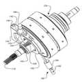
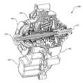
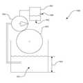
도 1은 스큐 기반 제어 시스템을 가지는 볼 유성 무한 가변 변속기(IVT)의 단면도이다.
도 2는 도 1의 IVT의 부분 단면 분해도이다.
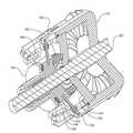
도 3은 도 1의 IVT의 내부 구성요소들의 사시도이다.
도 4는 도 1의 IVT의 내부 구성요소들의 평면도이다.
도 5는 도 1의 IVT와 사용될 수 있는 시프팅 구성요소들의 분해도이다.
도 6은 도 1의 IVT에 사용될 수 있는 제1 및 제2 캐리어 부재들의 일 실시예의 평면도이다.
도 7은 스큐 기반 제어 시스템을 가지는 무한 가변 변속기(IVT)의 단면도이다.
도 8은 도 7의 IVT의 단면 사시도이다.
도 9는 도 7의 IVT와 사용될 수 있는 캐리어 드라이버 링의 일 실시예의 단면도이다.
도 10은 도 9의 캐리어 드라이버 링의 사시도이다.
도 11은 도 9의 캐리어 드라이버 링의 평단면도이다.
도 12는 도 7의 IVT에 사용될 수 있는 캐리어 드라이버 링의 일 실시예의 평단면도이다.
도 13은 도 7의 IVT에 사용될 수 있는 캐리어 드라이버 링의 다른 실시예의 평단면도이다.
도 14는 스큐 기반 제어 시스템과 캐리어 드라이버 링을 가지는 IVT의 단면도이다.
도 15는 스큐 기반 제어 시스템과 선형으로 작동되는 캐리어 드라이버를 가지는 IVT의 일 실시예의 개략도이다.
도 16은 스큐 기반 제어 시스템과 선형으로 작동되는 캐리어 드라이버를 가지는 IVT의 일 실시예의 단면도이다.
도 17은 도 16의 IVT의 몇몇의 내부 시프팅 구성요소들의 부분 단면 사시도이다.
도 18은 도 17의 내부 시프팅 구성요소들의 평면도이다.
도 19는 도 18의 내부 시프팅 구성요소들의 A-A의 평면도이다.
도 20은 스큐 기반 제어 시스템을 가지는 IVT의 일 실시예의 부분 단면 사시도이다.
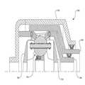
도 21은 도 20의 IVT의 단면도이다.
도 22는 도 20의 IVT의 분해 단면도이다.
도 23은 도 20의 IVT의 몇몇의 내부 구성요소들의 분해도이다.
도 24는 도 20의 IVT와 사용될 수 있는 토크 제한기의 단면도이다.
도 25는 도 24의 토크 제한기의 분해도이다.
도 26은 도 20의 IVT와 사용될 수 있는 맞물림 해제 메커니즘의 부분 단면도이다.
도 27은 도 26의 맞물림 해제 메커니즘의 단면도이다.
도 28은 도 26의 맞물림 해제 메커니즘의 다른 단면도이다.
도 29는 도 1 또는 20의 IVT와 사용될 수 있는 맞물림 해제 메커니즘의 일 실시예의 단면도이다.
도 30은 도 29의 맞물림 해제 메커니즘의 다른 단면도이다.
도 31은 도 20의 IVT와 사용될 수 있는 맞물림 해제 메커니즘의 사시도이다.
도 32는 도 31의 맞물림 해제 메커니즘의 단면도이다.
도 33은 도 31의 맞물림 해제 메커니즘의 다른 사시도이다.
도 34는 도 31의 맞물림 해제 메커니즘의 또 다른 단면도이다.
도 35는 도 20의 IVT와 사용될 수 있는 유압 시스템을 도시한 개략도이다.
도 36은 스큐 기반 제어 시스템을 가지는 IVT의 일 실시예의 단면도이다.
도 37은 도 36의 IVT의 몇몇의 구성요소들의 B-B의 평면도이다.
도 38은 도 36의 IVT와 사용될 수 있는 캐리어의 평면도이다.1 is a cross-sectional view of a ball planetary infinitely variable transmission (IVT) having a skew based control system.
FIG. 2 is a partial cross-sectional exploded view of the IVT of FIG. 1. FIG.
3 is a perspective view of internal components of the IVT of FIG. 1;
4 is a plan view of internal components of the IVT of FIG.
5 is an exploded view of shifting components that may be used with the IVT of FIG. 1.
FIG. 6 is a plan view of one embodiment of first and second carrier members that may be used in the IVT of FIG. 1. FIG.
7 is a cross-sectional view of an infinitely variable transmission IVT with a skew based control system.
8 is a cross-sectional perspective view of the IVT of FIG. 7.
9 is a cross-sectional view of one embodiment of a carrier driver ring that may be used with the IVT of FIG. 7.
10 is a perspective view of the carrier driver ring of FIG. 9.
FIG. 11 is a plan sectional view of the carrier driver ring of FIG. 9. FIG.
12 is a cross sectional plan view of one embodiment of a carrier driver ring that may be used in the IVT of FIG.
FIG. 13 is a plan sectional view of another embodiment of a carrier driver ring that may be used in the IVT of FIG. 7.
14 is a cross-sectional view of an IVT having a skew based control system and a carrier driver ring.
15 is a schematic diagram of one embodiment of an IVT with a skew based control system and a carrier driver operating linearly.
16 is a cross-sectional view of one embodiment of an IVT with a skew based control system and a carrier driver operating linearly.
17 is a partial cross-sectional perspective view of some internal shifting components of the IVT of FIG. 16.
18 is a top view of the internal shifting components of FIG. 17.
19 is a top view of AA of the internal shifting components of FIG. 18.
20 is a partial cross-sectional perspective view of one embodiment of an IVT having a skew based control system.
21 is a cross-sectional view of the IVT of FIG. 20.
22 is an exploded cross-sectional view of the IVT of FIG. 20.
FIG. 23 is an exploded view of some internal components of the IVT of FIG. 20.
24 is a cross-sectional view of a torque limiter that may be used with the IVT of FIG. 20.
25 is an exploded view of the torque limiter of FIG. 24.
FIG. 26 is a partial cross-sectional view of the disengagement mechanism that may be used with the IVT of FIG. 20.
FIG. 27 is a cross-sectional view of the disengagement mechanism of FIG. 26.
FIG. 28 is another cross-sectional view of the disengagement mechanism of FIG. 26.
29 is a cross-sectional view of one embodiment of an disengagement mechanism that may be used with the IVT of FIG. 1 or 20.
30 is another cross-sectional view of the disengagement mechanism of FIG. 29.
FIG. 31 is a perspective view of the disengagement mechanism that may be used with the IVT of FIG. 20.
32 is a cross-sectional view of the disengagement mechanism of FIG. 31.
33 is another perspective view of the disengagement mechanism of FIG.
FIG. 34 is another cross-sectional view of the disengagement mechanism of FIG. 31.
35 is a schematic diagram illustrating a hydraulic system that may be used with the IVT of FIG. 20.
36 is a cross-sectional view of one embodiment of an IVT having a skew based control system.
FIG. 37 is a top view of the BB of some components of the IVT of FIG. 36.
FIG. 38 is a top view of a carrier that may be used with the IVT of FIG. 36.
바람직한 실시예들이 첨부한 도면들을 참조하여 이제 설명될 것이며, 유사한 숫자들은 전체에 걸쳐 유사한 요소들을 가리킨다. 아래의 설명에서 사용되는 용어는 단순히 본 발명의 몇몇의 구체적인 실시예들의 상세한 설명과 함께 사용되기 때문에 임의의 제한되거나 한정적인 방식으로 해석되지 말아야 한다. 게다가, 본 발명의 실시예들은 특징들 중의 하나가 단독으로 이의 바람직한 속성들의 원인이 되지는 않거나 설명된 본 발명을 실시하는데 필수적이지는 않는 본 발명의 몇몇의 특징들을 포함할 수 있다. 여기에서 설명된 몇몇의 연속 가변 변속기(CVT)와 무한 가변 변속기(IVT)의 실시예들은 일반적으로 미국 특허번호들 6,241,636; 6,419,608; 6,689,012; 7,011,600; 7,166,052; 미국 특허 출원번호들 11/243,484 및 11/543,311; 및 특허 협력 조약(PCT) 특허 출원들 PCT/IB2006/054911, PCT/US2008/068929, PCT/US2007/023315, PCT/US2008/074496, 및 PCT/US2008/079879에 개시되는 타입과 관련된다. 각각의 이 특허들 및 특허 출원들의 전체 명세서는 여기에 참고로 포함된다.Preferred embodiments will now be described with reference to the accompanying drawings, wherein like numerals refer to like elements throughout. The terminology used in the following description is not to be construed in any limiting or limiting sense, because it is merely used with the description of some specific embodiments of the invention. In addition, embodiments of the present invention may include several features of the present invention in which one of the features is not solely responsible for its desirable attributes or is not essential to practicing the described invention. Some embodiments of the continuously variable transmission (CVT) and infinitely variable transmission (IVT) described herein are generally described in US Pat. Nos. 6,241,636; 6,419,608; 6,689,012; 7,011,600; 7,166,052; US patent applications Ser. Nos. 11 / 243,484 and 11 / 543,311; And the types disclosed in the Patent Cooperation Treaty (PCT) patent applications PCT / IB2006 / 054911, PCT / US2008 / 068929, PCT / US2007 / 023315, PCT / US2008 / 074496, and PCT / US2008 / 079879. The entire specification of each of these patents and patent applications is incorporated herein by reference.
여기에서 사용되는 바와 같이, 용어들 "작동되게 연결되는", "작동되게 결합되는", "작동되게 링크되는", "작동 가능하게 연결되는", "작동 가능하게 결합되는", "작동 가능하게 링크되는", 및 유사한 용어들은 요소들 사이의 관계(기계적인, 링크, 결합, 등)를 가리키며, 그에 의해 하나의 요소의 작동은 제2 요소의 상응하는, 뒤따르는, 또는 동시에 일어나는 작동이나 작용을 초래한다. 본 발명의 실시예들을 설명하기 위해 이런 용어들을 사용할 때, 요소들을 링크시키거나 결합시키는 특정한 구조들 또는 메커니즘들이 일반적으로 설명된다는 것이 주목된다. 그러나, 다르게 구체적으로 언급되지 않는 한, 이런 용어들 중의 하나가 사용될 때, 용어는 실제 링크 또는 결합이 몇몇의 예들에서 관련 기술분야에서 통상의 기술을 가진 사람에게 쉽게 명백해지는 다양한 형태들로 구현될 수 있다는 것을 가리킨다.As used herein, the terms “operably coupled”, “operably coupled”, “operably linked”, “operably coupled”, “operably coupled”, “operably coupled” "Linked", and similar terms refer to a relationship (mechanical, linking, joining, etc.) between elements, whereby the operation of one element is caused by the corresponding, following, or simultaneous operation of the second element. Brings about. When using these terms to describe embodiments of the invention, it is noted that the specific structures or mechanisms that link or couple the elements are generally described. However, unless specifically noted otherwise, when one of these terms is used, the term may be embodied in various forms in which the actual link or combination is readily apparent to some of ordinary skill in the art in some instances. Point out that you can.
설명을 위해, 용어 "반경방향의" 는 여기서 변속기 또는 배리에이터의 길이방향 축에 대하여 수직인 방향 또는 위치를 가리키는데 사용된다. 용어 "축방향의" 는 여기서 변속기 또는 배리에이터의 메인 또는 길이방향 축에 평행한 축에 따른 방향 또는 위치를 가리키는데 사용된다. 명확성과 간결성을 위해, 때때로 유사한 구성요소들은 유사하게 라벨이 붙여진다.For illustrative purposes, the term "radial" is used herein to refer to a direction or position perpendicular to the longitudinal axis of the transmission or variator. The term "axial" is used herein to refer to a direction or position along an axis parallel to the main or longitudinal axis of the transmission or variator. For clarity and brevity, sometimes similar components are similarly labeled.
여기서 "견인(traction)" 에 대한 언급은 지배적이거나 독점적인 방식의 파워 전달이 "마찰" 을 통해서 일어나는 적용들을 제외하지 않는다는 것이 주목되어야 한다. 여기서 견인 구동장치와 마찰 구동장치 사이의 분류상의 차이를 설정하려고 시도하지 않고, 일반적으로 이들은 파워 전달의 상이한 체제로서 이해될 수 있다. 견인 구동장치들은 통상적으로 요소들 사이에 잡힌 얇은 유체 층에 있는 전단력에 의한 두 개의 요소들 사이의 파워의 전달을 수반한다. 이런 적용들에 사용되는 유체들은 통상적으로 종래의 미네랄 오일들보다 큰 견인 계수들을 나타낸다. 견인 계수(μ)는 접촉하는 구성요소들의 인터페이스들에서 이용 가능하고 최대 이용 가능 구동 토크의 척도인 최대 이용 가능 견인력을 나타낸다. 일반적으로, 마찰 구동장치들은 일반적으로 요소들 사이의 마찰력에 의한 두 개의 요소들 사이의 파워 전달에 관한 것이다. 본 명세서를 위해, 여기에서 설명되는 IVT들은 견인 및 마찰 적용들에서 작동될 수 있다는 것이 이해되어야 한다. 예를 들면, IVT가 자전거에 대한 적용에 사용되는 실시예에서, IVT는 작동 중에 존재하는 토크와 속도 조건들에 따라, 때때로 마찰 구동장치로서 그리고 다른 때에는 견인 구동장치로서 작동될 수 있다.It should be noted here that reference to "traction" does not exclude applications in which dominant or proprietary modes of power transfer occur through "friction". Here no attempt is made to establish a classification difference between the traction drive and the friction drive, and in general they can be understood as different regimes of power transmission. Traction drives typically involve the transfer of power between two elements by shear forces in a thin fluid layer held between the elements. Fluids used in such applications typically exhibit greater traction coefficients than conventional mineral oils. The traction coefficient μ represents the maximum available traction force that is available at the interfaces of the components in contact and is a measure of the maximum available drive torque. In general, friction drives generally relate to the transmission of power between two elements by the frictional force between the elements. For the purposes of this specification, it should be understood that the IVTs described herein may be operated in traction and friction applications. For example, in embodiments where the IVT is used for applications to bicycles, the IVT may be operated as a friction drive and sometimes as a traction drive, depending on the torque and speed conditions present during operation.
여기에서 개시된 본 발명의 실시예들은 작동 중에 출력 속도에 대한 입력 속도의 원하는 비율을 달성하도록 조절될 수 있는 (때때로 여기서 "유성 회전축" 으로 언급되는) 틸팅 가능한 회전 축을 각각 가지는 일반적으로 구형의 유성들을 사용하는 배리에이터 및/또는 IVT의 제어와 관련된다. 몇몇의 실시예들에서, 이런 회전 축의 조절은 제2 평면에서 유성 회전 축의 각도 조절을 달성하고, 그에 의해 배리에이터의 속도 비율을 조절하기 위해 제1 평면에서 유성 축의 각도 오정렬을 수반한다. 제1 평면에서의 각도 오정렬은 여기서 "스큐" 또는 "스큐 각도" 로서 언급된다. 이 타입의 배리에이터 제어는 일반적으로 미국 특허 출원번호들 12/198,402와 12/251,325에서 설명되며, 각각의 이 특허 출원들의 전체 명세서는 여기에 참고로 포함된다. 일 실시예에서, 제어 시스템은 제2 평면에서 유성 회전 축을 틸팅시키는 배리에이터에 있는 몇몇의 접촉하는 구성요소들 사이에 힘을 발생시키기 위해 스큐 각도의 사용을 조정한다. 유성 회전 축의 틸팅은 배리에이터의 속도 비율을 조절한다. 배리에이터의 원하는 속도 비율을 얻기 위한 (때때로 여기서 "스큐 기반 제어 시스템들" 로 언급되는) 스큐 제어 시스템들 및 스큐 각도 작동 장치들의 실시예들이 논의될 것이다.Embodiments of the present invention disclosed herein generally employ spherical planetary planets each having a tiltable rotational axis (sometimes referred to herein as a "planetary rotational axis") that can be adjusted to achieve a desired ratio of input speed to output speed during operation. Control of the variator and / or IVT used. In some embodiments, this adjustment of the rotational axis involves angular misalignment of the planetary axis in the first plane to achieve an angle adjustment of the planetary rotational axis in the second plane, thereby adjusting the speed ratio of the variator. Angular misalignment in the first plane is referred to herein as "skew" or "skew angle". This type of variator control is generally described in U.S. Patent Application Nos. 12 / 198,402 and 12 / 251,325, the entire specification of each of which is hereby incorporated by reference. In one embodiment, the control system adjusts the use of the skew angle to generate a force between several contacting components in the variator that tilts the planetary axis of rotation in the second plane. Tilting of the planetary axis of rotation regulates the speed ratio of the variator. Embodiments of skew control systems and skew angle actuators (sometimes referred to herein as "skew based control systems") to obtain the desired speed ratio of the variator will be discussed.
무한 가변 변속기(IVT) 및 이의 구성요소들과 서브어셈블리들의 실시예들은 도 1 내지 도 38을 참조하여 이제 설명될 것이다. 두 개의 디스크와 같은 변속기 부재들 사이의 상대적인 각도 위치를 제어하기 위한 시프팅 메커니즘들의 실시예들이 또한 설명될 것이다. 이런 시프팅 메커니즘들은 많은 상이한 타입의 무한 가변 변속기들에 대한 제어를 개선시킬 수 있으며, 설명을 하기 위해 여기에서 몇몇의 실시예들에서 보여진다. 도 1은 인력 구동 차량들(예를 들면, 자전거들), 경량 전기 차량들, 인력, 전기, 또는 내연 구동 하이브리드 차량들, 산업 설비, 풍력 터빈들, 등을 포함하지만 이들에 한정되지 않는 많은 적용들에 사용될 수 있는 IVT(100)를 도시한다. 파워 입력과 파워 싱크(예를 들면, 부하장치) 사이의 기계적인 파워 전달의 조절을 필요로 하는 임의의 기술적 적용은 이의 파워 트레인에 있는 IVT(100)의 실시예들을 실행시킬 수 있다.Embodiments of the infinitely variable transmission IVT and its components and subassemblies will now be described with reference to FIGS. 1 to 38. Embodiments of shifting mechanisms for controlling the relative angular position between transmission members, such as two disks, will also be described. Such shifting mechanisms can improve control for many different types of infinitely variable transmissions, which are shown in some embodiments herein for illustrative purposes. 1 includes many applications including, but not limited to, manpower driven vehicles (eg bicycles), lightweight electric vehicles, manpower, electric or internal combustion driven hybrid vehicles, industrial equipment, wind turbines, and the like. 4 illustrates an
이제 도 1 및 도 2를 참조하면, 일 실시예에서, IVT(100)는 하우징 캡(104)에 결합되는 하우징(102)을 포함한다. 하우징(102)과 하우징 캡(104)은 풀리(106)와 같은 파워 입력 인터페이스 및 액추에이터 커플링(108)과 같은 제어 인터페이스를 지지한다. 풀리(106)는 내연 엔진(도시되지 않음)과 같은 회전 파워 소스에 의해 구동되는 구동 벨트에 결합될 수 있다. 일 실시예에서, IVT(100)는 IVT(100)의 길이방향 축을 실질적으로 한정하는 메인 샤프트(110)가 구비된다. 메인 샤프트(110)는 풀리(106)에 결합된다. 메인 샤프트(110)는 하우징 캡(104)에 있는 베어링(112)에 의해 지지된다. IVT(100)는 메인 샤프트(110)에 대해 각도를 이루어 배치되는 복수의 견인 유성 어셈블리들(114)을 포함한다. 각각의 견인 유성 어셈블리(114)는 제1 및 제2 캐리어 부재들(116, 118) 각각에 결합된다. 메인 샤프트(110)는 제1 캐리어 부재(116)에 결합된다. 제1 및 제2 캐리어 부재들(116, 118)은 메인 샤프트(110)와 동축상에 있다. 일 실시예에서, 각각의 견인 유성 어셈블리(114)는 제1 및 제2 견인 링들(120, 122) 각각에 결합된다. 각각의 견인 유성 어셈블리(114)는 반경방향 내측의 위치에서 아이들러 어셈블리(121)와 접촉한다. 제1 견인 링(120)은 제1 축방향 힘 발생기 어셈블리(124)에 결합된다. 제1 견인 링(120)과 제1 축방향 힘 발생기 어셈블리(124)는 하우징(102)에 대한 회전이 실질적으로 불가능하다. 일 실시예에서, 제1 축방향 힘 발생기 어셈블리(124)는 그라인딩된 링(125)에 결합된다. 그라인딩된 링(125)은 하우징 캡(104)으로부터 연장되는 쇼울더(123)에 부착된다. 제2 견인 링(122)은 제2 축방향 힘 발생기(126)에 결합된다. 제2 견인 링(122)과 제2 축방향 힘 발생기(126)는 출력 파워 인터페이스(128)에 결합된다. 출력 파워 인터페이스(128)는 부하장치(도시되지 않음)에 결합될 수 있다. 일 실시예에서, 출력 파워 인터페이스(128)는 부하장치로부터 제2 견인 링(122)을 기계적으로 분리시키도록 구성되는 맞물림 해제 메커니즘(130)을 포함한다.Referring now to FIGS. 1 and 2, in one embodiment, the
이제 도 1 내지 도 4를 참조하면, 일 실시예에서, IVT(100)는 시프트 제어 메커니즘(140)과 사용될 수 있다. 시프트 제어 메커니즘(140)은 다른 타입의 변속기들과 사용될 수 있으며, 일 예로서 IVT(100)와 여기에서 보여진다. 시프트 제어 메커니즘(140)은 로커 암(142)에 결합되는 액추에이터 커플링(108)을 포함할 수 있다. 로커 암(142)은 피봇 핀(146)을 중심으로 회전되도록 구성되는 시프트 포크(144)에 결합된다. 일 실시예에서, 피봇 핀(146)은 길이방향 축으로부터 편향된다. 시프트 포크(144)는 시프트 칼라(148)에 결합된다. 시프트 칼라(148)는 베어링(150)을 지지한다. 베어링(150)은 캐리어 드라이버 너트(152)에 결합된다. 캐리어 드라이버 너트(152)는 메인 샤프트(110)와 제1 캐리어 부재(116)에 결합된다.Referring now to FIGS. 1-4, in one embodiment, the
이제 도 5를 참조하고 여전히 도 1 내지 도 4를 참조하면, 일 실시예에서, 로커 암(142)은 피봇(143)에 회전 가능하게 결합된다. 피봇(143)은 시프트 포크(144)에 부착되는 다월(dowel)일 수 있다. 시프트 포크(144)는 슬롯들(154)의 세트를 가질 수 있다. 슬롯들(154)은 시프트 칼라(148)에 부착되는 맞물림 다월들(156)의 세트를 안내한다. 일 실시예에서, 시프트 칼라(148)는 네 개의 맞물림 다월들(156)이 구비된다. 몇몇의 실시예들에서, 두 개의 맞물림 다월들(156)이 슬롯들(154)에서 이동하도록 배치되며 두 개의 맞물림 다월들(156)은 하우징 캡(104)의 쇼울더(123)에 형성되는 슬롯들(155) 의 세트에서 이동하도록 배치된다(도 2). 일 실시예에서, 캐리어 드라이버 너트(152)는 나선형 스플라인들로 형성되는 내부 구멍(158)을 가진다. 내부 구멍(158)은 메인 샤프트(110)의 위에 형성되는 정합 나선형 스플라인들(160)에 결합된다. 캐리어 드라이버 너트(152)는 내부 구멍(158)으로부터 외측으로 반경방향으로 연장되는 다수의 가이드 표면들(162)이 구비된다. 가이드 표면들(162)은 제1 캐리어 부재(116)의 위에 형성되는 정합 가이드 표면들(164)에 결합된다.Referring now to FIG. 5 and still with reference to FIGS. 1-4, in one embodiment, the
이제 도 6으로 가면, 일 실시예에서, 제2 캐리어 부재(118)는 중앙 구멍(171)의 주위에 각도를 이루어 배치되는 다수의 가이드 슬롯들(170)이 구비될 수 있다. 가이드 슬롯들(170)은 도 6의 페이지의 평면에서 관찰할 때 반경방향 작도 라인(76)에 정렬된다. 가이드 슬롯들(170)은 유성 액슬(115)의 일 단부를 받아들이도록 구성된다(도 1). 몇몇의 실시예들에서, 가이드 슬롯들(170)의 반경방향 내측 부분(172)은 견인 유성 액슬(115)을 수용하기 위한 크기로 만들어진 곡선형 프로파일들로 형성된다. 일 실시예에서, 제1 캐리어 부재(116)는 중앙 구멍(175)의 주위에 각도를 이루어 배치되는 다수의 반경방향으로 편향된 가이드 슬롯들(174)이 구비된다. 각각의 반경방향으로 편향된 가이드 슬롯(174)은 유성 액슬(115)에 대한 제1 캐리어 부재(116)의 커플링을 수용하기 위한 크기로 만들어진다. 반경방향으로 편향된 가이드 슬롯들(174)은 도 6의 페이지의 평면에서 관찰할 때 반경방향 작도 라인(76)으로부터 각도상으로 편향된다. 각도 편향은 각도(88)에 의해 근사치로 계산될 수 있다. 각도(88)는 반경방향 작도 라인(76)과 작도 라인(90) 사이에 형성된다. 작도 라인(90)은 도 6의 페이지의 평면에서 관찰할 때 반경방향으로 편향된 가이드 슬롯(174)을 대체로 2등분한다. 몇몇의 실시예들에서, 각도(88)는 3도와 45도 사이이다. 낮은 각도(88)는 잘 반응하는 변속 비율 변화를 생성하지만 잠재적으로 제어하거나 안정화시키는 것이 더 어려운 반면에 높은 각도는 변속 비율 변화에 잘 반응하지 않을 수 있지만 그에 비해 제어하기가 쉽다. 높은 속도의, 빠른 시프트율을 가지는 것이 바람직한 몇몇의 실시예들에서, 각도(88)는, 예를 들면, 10도일 수 있다. 변속 비율의 더 느린 속도의, 정밀한 제어를 가지는 것이 바람직한 다른 실시예들에서, 각도(88)는 약 30도일 수 있다. 그러나, 각도(88)의 이런 값들은 설명을 위한 예로서 제공되며, 각도(88)는 설계자가 원하는 임의의 방식으로 변경될 수 있다. 몇몇의 실시예들에서, 각도(88)는 이들의 사이 또는 이들의 비정수들에 있는 임의의 각도를 포함하는 10 내지 25도의 범위에 있는 임의의 각도일 수 있다. 예를 들면, 각도(88)는 10, 11, 12, 13, 14, 15, 16, 17, 18, 19, 20, 21, 22, 23, 24, 25, 또는 이들의 임의의 부분일 수 있다. 다른 실시예들에서, 각도(88)는 20도일 수 있다. 일 실시예에서, 반경방향으로 편향된 가이드 슬롯들(174)은 작도 라인(90)이 거리(92)로 작도 라인(91)으로부터 반경방향으로 편향되도록 배치될 수 있다. 작도 라인(91)은 작도 라인(90)에 평행하며 제1 캐리어 부재(116)의 중심과 교차한다.Referring now to FIG. 6, in one embodiment, the
IVT(100)의 작동 중에, 변속 비율의 변화는 액추에이터 커플링(108)을 회전시킴으로써 달성된다. 몇몇의 실시예들에서, 액추에이터 커플링(108)은 사용자의 손으로 작동되는 기계적인 링크일 수 있는 사용자 제어장치(도시되지 않음)에 부착된다. 다른 실시예들에서, 액추에이터 커플링(108)은 IVT(100)에 대한 원하는 변속 비율을 가리키는 액추에이터 커플링(108)에 회전 운동을 제공할 수 있는 전기 또는 유압 액추에이터에 결합될 수 있다. 액추에이터 커플링(108)이 길이방향 축에 대해 축방향으로 고정되기 때문에, 액추에이터 커플링(108)의 회전은 로커 암(142)을 회전시키고 그에 의해 피봇(143)을 회전시키고 축방향으로 이동시키는 경향이 있다. 피봇(143)의 운동은 피봇 핀(146)을 중심으로 시프트 포크(144)를 회전시키는 경향이 있다. 피봇 핀(146)은 메인 샤프트(110)로부터 편향되며 그 결과로 피봇 핀(146)을 중심으로 하는 시프트 포크(144)의 회전은 슬롯들(154)의 축방향 이동에 상응한다. 슬롯들(154)의 축방향 이동은 메인 샤프트(110)에 대해 시프트 칼라(148)를 축방향으로 이동시키는 경향이 있다. 캐리어 드라이버 너트(152)는 시프트 칼라(148)에 작동 가능하게 결합되기 때문에, 시프트 칼라(148)의 축방향 이동은 캐리어 드라이버 너트(152)의 축방향 이동에 상응한다. 캐리어 드라이버 너트(152)는 메인 샤프트(110)의 나선형 스플라인들(160)에 결합된다. 캐리어 드라이버 너트(152)의 축방향 이동은 메인 샤프트(110)에 대한 캐리어 드라이버 너트(152)의 상대적인 회전을 용이하게 한다. 캐리어 드라이버 너트(152)는 제1 캐리어 부재(116)의 가이드 표면들(164)을 맞물기 때문에, 메인 샤프트(110)에 대한 캐리어 드라이버 너트(152)의 회전은 메인 샤프트(110)에 대한 제1 캐리어 부재(116)의 회전에 상응한다. 제2 캐리어 부재(118)에 대한 제1 캐리어 부재(116)의 회전은 IVT(100)의 변속 비율을 변경시키는 경향이 있다.During operation of the
설계자가 액추에이터 커플링(108)에 적용되는 회전과 캐리어 드라이버 너트(152)의 축방향 이동 사이의 원하는 관계를 달성하기 위해 슬롯들(154)에 대한 로커 암(142), 피봇(143), 및 피봇 핀(146)의 위치를 구성할 수 있다는 것이 주목되어야 한다. 몇몇의 실시예들에서, 설계자는 변속 비율의 변화를 달성하기 위해 액추에이터 커플링(108)에 가해지는 요구되는 힘 또는 토크를 제공하기 위해 로커 암(142), 피봇(143), 및 피봇 핀(146)의 위치를 선택할 수 있다. 유사하게, 설계자는 캐리어 드라이버 너트(152)의 축방향 변위와 제1 캐리어 부재(116)의 회전 사이의 원하는 관계를 달성하기 위해 나선형 스플라인들(160)의 피치와 리드를 선택할 수 있다.The
다시 도 5 및 도 6을 참조하면, 일 실시예에서, IVT(100)는 펌프 어셈블리(180)가 구비될 수 있다. 펌프 어셈블리(180)는 제1 캐리어 부재(116)의 위에 형성되는 로브(184)에 결합되는 펌프 드라이버(182)를 포함한다. 펌프 어셈블리(180)는 펌프 드라이버(182)에 부착되는 펌프 플런저(186)를 포함한다. 펌프 플런저(186)는 밸브 몸체(188)와 밸브 플런저(190)를 둘러싼다. 일 실시예에서, 로브(184)는 제1 캐리어 부재(116)의 중심(192)으로부터 편향된 중심(191)을 가진다(도 6). 몇몇의 실시예들에서, 로브(184)는 메인 샤프트(110)의 위에 또는 리테이닝 너트(193)의 위에 형성될 수 있으며, 유사하게, 펌프 어셈블리(180)는 축방향으로 적절하게 위치하며 그 결과로 펌프 드라이버(182)가 로브(184)를 맞물 수 있다. IVT(100)의 작동 중에, 메인 샤프트(110)는 길이방향 축을 중심으로 회전되며 그에 의해 제1 캐리어 부재(116)를 구동시킨다. 로브(184)는 제1 캐리어 부재(116)가 길이방향 축을 중심으로 회전될 때 왕복 운동으로 펌프 드라이버(182)를 구동시킨다. 일 실시예에서, 그라인딩된 링(125)은 펌프 드라이버(182)를 수용하도록 구성된 가이드 홈(194)이 구비된다. 그라인딩된 링(125)은 또한 맞물림 다월들(156)과 시프트 포크(144)에 대한 클리어런스를 제공하는데 적절한 크기로 만들어진 다수의 클리어런스 릴리프들(196)이 구비될 수 있다.Referring again to FIGS. 5 and 6, in one embodiment, the
이제 도 7 내지 도 10으로 가면, IVT(200)는 길이방향 축(204)의 주위에 각도를 이루어 배치되는 다수의 견인 유성 어셈블리들(202)을 포함할 수 있다. 명확성을 위해, IVT(200)의 하우징과 몇몇의 내부 구성요소들은 도시되지 않는다. 각각의 견인 유성 어셈블리(202)는 유성 액슬(206)이 구비된다. 유성 액슬들(206)은 제1 및 제2 캐리어 부재들(208, 210) 각각에 작동 가능하게 결합된다. 제1 및 제2 캐리어 부재들(208, 210)은 제1 및 제2 캐리어 부재들(116, 118) 각각과 대체로 유사할 수 있다. 일 실시예에서, 제1 및 제2 캐리어 부재들(208, 210)은 회전 파워 소스(도시되지 않음)에 결합된다. IVT(200)는 각각의 견인 유성 어셈블리들(202)의 외측으로 반경방향으로 위치하는 캐리어 드라이버 링(212)이 구비된다. 캐리어 드라이버 링(212)은 베어링들(215)의 세트에 의해 시프트 클레비스(shift clevis, 214)에 결합된다. 베어링(215)은, 예를 들면, 복수의 다월들(217)로 캐리어 드라이버 링(212)에 회전이 구속될 수 있다. 일 실시예에서, 시프트 클레비스(214)는 나사 구멍(213)이 구비된다. 나사 구멍(213)은 일반적으로 길이방향 축(204)에 평행하다. 나사 구멍(213)은 시프트 클레비스(214)의 축방향 이동을 용이하게 하기 위해 나사 시프트 로드(도시되지 않음)에 결합될 수 있다.Turning now to FIGS. 7-10, the
도 9 및 10을 구체적으로 참조하면, 캐리어 드라이버 링(212)은 캐리어 드라이버 링(212)의 내주의 위에 형성되는 길이방향 홈들(220)의 세트를 가진다. 길이방향 홈들(220)은 길이방향 축(204)에 대체로 평행이다. 캐리어 드라이버 링(212)은 내주의 위에 형성되는 편향된 길이방향 홈들(222)의 세트를 가진다. 편향된 길이방향 홈들(222)은 길이방향 축(204)에 대해 각도를 형성한다. 편향된 길이방향 홈들(222)은 도 9의 평면에서 관찰할 때 길이방향 축(204)에 대한 각도(224)를 형성한다. 몇몇의 실시예들에서, 각도(224)는 이들의 사이 또는 이들의 비정수들에 있는 임의의 각도를 포함하는 0 내지 30도의 범위에 있는 임의의 각도일 수 있다. 예를 들면, 각도(224)는 0, 1, 2, 3, 4, 5, 6, 7, 8, 9, 10, 11, 12, 13, 14, 15, 16, 17, 18, 19, 20, 21, 22, 23, 24, 25, 26, 27, 28, 29, 30 또는 이들의 임의의 부분일 수 있다. 일 실시예에서, 제1 캐리어 부재(208)는 다수의 다월들(228)이 구비된다. 다월들(228)은 길이방향 홈들(220)에 결합되고 이들에 의해 안내된다. 제2 캐리어 부재(210)는 다수의 다월들(230)이 구비된다. 다월들(230)은 편향된 길이방향 홈들(222)에 결합되며 이들에 의해 안내된다.9 and 10, the
IVT(200)의 작동 중에, 변속 비율의 변화는 시프트 클레비스(214)를 축방향으로 이동시킴으로써 달성될 수 있다. 시프트 클레비스(214)의 축방향 이동은 캐리어 드라이버 링(212)을 축방향으로 이동시키는 경향이 있다. 캐리어 드라이버 링(212)의 축방향 이동은 홈들(220, 222) 각각에서 다월들(228, 230)을 안내하는 경향이 있다. 제1 및 제2 캐리어 부재들(208, 210)이 축방향으로 대체로 고정되기 때문에, 제1 및 제2 캐리어 부재들(208, 210)은 다월들(228, 230)이 홈들(220, 222) 각각에서 축방향으로 이동될 때 서로에 대해 회전된다.During operation of the
이제 도 11 내지 도 13을 구체적으로 참조하면, 캐리어 드라이버 링(212)의 위에 형성되는 길이방향 홈들은 제2 캐리어 부재(210)에 대한 제1 캐리어 부재(208)의 원하는 상대적인 회전을 제공하기 위해 많은 형태들을 취할 수 있다. 예를 들면, 도 11은 길이방향 홈(220)과 편향된 길이방향 홈(222)을 도시한다. 캐리어 드라이버 링(212)의 일 측에서 홈들(220, 222)은 거리(232)에 의해 분리된다. 캐리어 드라이버 링(212)의 다른 측에서 홈들(220, 222)은 거리(234)에 의해 분리된다. 도 12에 도시된 실시예에서, 캐리어 드라이버 링(212)은 길이방향 홈들(220)과 곡선형 홈(236)의 세트가 구비된다. 도 13에 도시된 실시예에서, 캐리어 드라이버 링(212)은 양으로 편향된 길이방향 홈들(238)의 세트와 음으로 편향된 길이방향 홈들(240)의 세트가 구비된다. 여기에서 설명된 실시예들은 설명하기 위한 것이며 캐리어 링(212)의 위에 형성되는 홈들의 형상과 치수는 원하는 시프트 성능을 달성하기 위해 설계자에 의해 구성될 수 있다는 것이 주목되어야 한다. 예를 들면, 길이방향 홈들(220)과 편향된 길이방향 홈들(222) 사이의 거리(232)는 캐리어 드라이버 링(212)의 다른 측 상의 거리(234)보다 짧을 수 있다. 거리들(232, 234) 사이의 차이는 길이방향 축(204)을 따른 캐리어 드라이버 링(212)의 축방향 이동에 관련하여 제2 캐리어 부재(210)에 대한 제1 캐리어 부재(208)의 원하는 회전을 생성하도록 구성될 수 있다.Referring now specifically to FIGS. 11-13, the longitudinal grooves formed on the
이제 도 14로 가면, 일 실시예에서, IVT(300)는 IVT(200)와 대체로 유사할 수 있다. IVT(300)는 IVT(300)의 내부 구성요소들을 대체로 둘러싸도록 구성되는 하우징(302)을 포함할 수 있다. IVT(300)는 캐리어 드라이버 링(304)이 구비될 수 있다. 캐리어 드라이버 링(304)은 캐리어 드라이버 링(212)과 유사한 방식으로 제1 및 제2 캐리어 부재들(208, 210)에 결합될 수 있다. 캐리어 드라이버 링(304)은 모터(도시되지 않음)와 같은 액추에이터에 의해 축방향으로 이동되도록 구성될 수 있다. 일 실시예에서, 캐리어 드라이버 링(304)은 출력 링(306) 상에 반경방향으로 지지된다. 출력 링(306)은 각각의 견인 유성 어셈블리들(202)에 작동 가능하게 결합된다.Referring now to FIG. 14, in one embodiment, the
이제 도 15로 되돌아가면, 일 실시예에서, IVT(400)는 메인 샤프트(404)의 주위에 각도를 이루어 배치되는 다수의 견인 유성 어셈블리들(402)을 가질 수 있다. 각각의 견인 유성 어셈블리(402)는 제1 및 제2 견인 링들(406, 408) 각각에 결합된다. 각각의 견인 유성 어셈블리(402)는 아이들러 어셈블리(410)에 결합된다. 아이들러 어셈블리(410)는 각각의 견인 유성 어셈블리(402)의 내측으로 반경방향으로 위치된다. 일 실시예에서, 각각의 견인 유성 어셈블리(402)는 제1 및 제2 캐리어 부재들(412, 414)에 결합된다. 제1 및 제2 캐리어 부재들(412, 414)은 제1 및 제2 캐리어 부재들(116, 118) 각각과 대체로 유사할 수 있다. 일 실시예에서, 제1 캐리어 부재(412)는 메인 샤프트(404)에 견고하게 부착된다. 제1 및 제2 캐리어 부재들(412, 414)과 메인 샤프트(404)는 회전 파워 소스(도시되지 않음)에 작동 가능하게 결합되도록 구성될 수 있다. 제2 캐리어 부재(414)는 제1 캐리어 부재(412)에 대해 회전되도록 구성된다. 일 실시예에서, 제2 캐리어 부재(414)는 토션 플레이트(416)에 결합된다. 토션 플레이트(416)는 제2 캐리어 부재(414)와 동축상에 있으며 스플라인들, 용접, 또는 다른 적당한 고정 수단으로 제2 캐리어 부재(414)에 견고하게 부착될 수 있다. 일 실시예에서, 토션 플레이트(416)는 회전 방향으로 강성이 있거나 빳빳하지만 토션 플레이트들에서 일반적인 것과 같이 축방향으로 어느 정도의 유연성을 가진다. 축방향의 이런 정도의 유연성은 토션 플레이트(416)에 대한 스프링과 같은 순응성을 제공한다. 토션 플레이트(416)는 반경방향 내측의 위치에서 캐리어 드라이버 너트(418)에 결합된다. 캐리어 드라이버 너트(418)는 메인 샤프트(404)의 위에 형성되는 정합 나선형 스플라인들을 맞물기 위해 배치되는 나선형 스플라인들(420)로 형성되는 내부 구멍을 가진다. 캐리어 드라이버 너트(418)는 액추에이터 커플링(422)에 작동 가능하게 결합된다. 일 실시예에서, 액추에이터 커플링(422)은 도 15에 벡터(424)로서 도시된 힘을 생성하는 서보 모터 또는 수동 레버(도시되지 않음)와 같은 리니어 액추에이터에 결합된다. 일 실시예에서, 액추에이터 커플링(422)은 메인 샤프트(404)를 중심으로 한 회전이 실질적으로 불가능하다.Turning now to FIG. 15, in one embodiment, the
IVT(400)의 작동 중에, 변속 비율의 변화는 축방향으로 이동되는 액추에이터 커플링(422)에 의해 달성된다. 액추에이터 커플링(422)의 축방향 이동은 캐리어 드라이버 너트(418)를 축방향으로 이동시키는 경향이 있다. 캐리어 드라이버 너트(418)가 나선형 스플라인들(420)에서 메인 샤프트(404)를 맞물기 때문에, 메인 샤프트(404)에 대한 캐리어 드라이버 너트(418)의 축방향 이동은 캐리어 드라이버 너트(418)와 메인 샤프트(404) 사이의 상대적인 회전을 용이하게 하는 경향이 있다. 토션 플레이트(416)는 캐리어 드라이버 너트(418)가 회전될 때 회전되며, 이는 제1 캐리어 부재(412)에 대해 제2 캐리어 부재(414)를 회전시키는 경향이 있다.During operation of the
이제 도 16 내지 도 19를 참조하면, 일 실시예에서, IVT(500)는 아이들러 어셈블리(504)와 접촉하며 이의 반경방향으로 외측에 있는 다수의 견인 유성 어셈블리들(502)이 구비될 수 있다. 각각의 견인 유성 어셈블리(502)는 제1 및 제2 견인 링들(506, 508) 각각과 접촉한다. 일 실시예에서, 제1 견인 링(506)은 회전이 실질적으로 불가능하다. IVT(500)는 출력 샤프트(510)가 구비될 수 있다. 출력 샤프트(510)는 제2 견인 링(508)을 맞물도록 구성되는 통상의 축방향 힘 발생기 커플링(512)에 결합된다. 각각의 견인 유성 어셈블리(502)는 제1 및 제2 캐리어 부재들(514, 516) 각각에 의해 안내되고 지지된다. 제1 및 제2 캐리어 부재들(514, 516)은 각각 가이드 슬롯들(513, 515)이 구비된다. 일 실시예에서, 가이드 슬롯들(513, 515)은 각각 가이드 슬롯들(170, 174)와 대체로 유사하다. 제1 및 제2 캐리어 부재들(514, 516)은 회전 파워 소스(도시되지 않음)로부터 나온 파워 입력을 받아들이도록 구성된다. 일 실시예에서, 입력 샤프트(518)는 캐리어 기어(522)를 맞무는 구동 기어(520)에 결합될 수 있다. 캐리어 기어(522)는 제1 및 제2 캐리어 부재들(514, 516)로의 파워의 전달을 용이하게 한다. 출력 샤프트(510)는, 예를 들면, 하우징(524)에 대해 베어링에 의해 지지될 수 있다. 일 실시예에서, 하우징(524)은 IVT(500)의 내부 구성요소들을 대체로 둘러싸기 위해 함께 고정되는 두 개의 부분들로 형성된다.Referring now to FIGS. 16-19, in one embodiment, the
일 실시예에서, IVT(500)는 IVT(500)의 길이방향 축을 실질적으로 한정하는 중심 샤프트(526)가 구비된다. 중심 샤프트(526)는 제1 및 제2 캐리어 부재들(514, 516)을 지지하도록 구성될 수 있다. 몇몇의 실시예들에서, 제2 캐리어 부재(516)는 중심 샤프트(526)에 견고하게 부착된다. 제1 캐리어 부재(514)는 중심 샤프트(526)에 위치될 수 있으며 그 결과로 제1 캐리어 부재(514)는 제2 캐리어 부재(516)에 대해 회전될 수 있다. 중심 샤프트(526)의 일 단부는 액추에이터 커플링(528)을 지지하도록 구성될 수 있다. 일 실시예에서, 베어링(529)은 중심 샤프트(514)에 대해 액추에이터 커플링(528)을 지지한다. 베어링(529)은 중심 샤프트(526)에 대한 액추에이터 커플링(528)의 축방향 이동을 허용하도록 구성된다. 액추에이터 커플링(528)은 스플라인들로 하우징(524)에 부착되며 중심 샤프트(526)에 대해 실질적으로 회전이 불가능하다. 일 실시예에서, 액추에이터 커플링(528)은 액추에이터 커플링(528)의 축방향 이동을 용이하게 하기 위해 리니어 액추에이터(도시되지 않음)에 결합된다. 액추에이터 커플링(528)은 캐리어 드라이버 허브(532)에 베어링(530)으로 결합된다. 캐리어 드라이버 허브(532)는 제1 및 제2 캐리어 부재들(514, 516)에 결합된다.In one embodiment,
이제 도 17 내지 도 19를 구체적으로 참조하면, 캐리어 드라이버 허브(532)는 대체로 원통형 몸체로부터 연장되는 다수의 로드들(534)이 구비될 수 있다. 각각의 로드들(534)은 롤러(536)가 구비된다. 로드들(534)은 제2 캐리어 부재(516)의 위에 형성되는 다수의 길이방향 슬롯들(538)을 맞문다. 롤러들(536)은 제1 캐리어 부재(514)의 위에 형성되는 다수의 길이방향 슬롯들(540)을 맞문다. 길이방향 슬롯들(538)은 IVT(500)의 길이방향 축과 대체로 평행하다. 길이방향 슬롯들(540)은 도 19의 페이지의 평면에서 관찰할 때 IVT(500)의 길이방향 축에 대해 각도를 형성한다.Referring now specifically to FIGS. 17-19, the
IVT(500)의 작동 중에, 변속 비율의 변화는 액추에이터 커플링(528)을 축방향으로 이동시킴으로써 달성된다. 액추에이터 커플링(528)의 축방향 이동은 캐리어 드라이버 허브(532)를 축방향으로 이동시키는 경향이 있다. 캐리어 드라이버 허브(532)가 축방향으로 이동될 때, 로드들(534)과 롤러들(536)은 각각 길이방향 슬롯들(538, 540)을 따라 축방향으로 이동된다. 길이방향 슬롯들(540)이 길이방향 슬롯들(540)에 대해 각도를 형성하기 때문에, 로드들(534)과 롤러들(536)의 축방향 이동은 제1 캐리어 부재(514)와 제2 캐리어 부재(516) 사이의 상대적인 회전을 야기하며, 그에 의해 IVT(500)의 비율을 변화시키는 경향이 있다. 몇몇의 실시예들에서, IVT(500)는 IVT(500)의 축방향 일 단부로 캐리어 드라이버 허브(532)를 가압하도록 구성되는 스프링(542)이 구비될 수 있다.During operation of the
이제 도 20 및 도 21을 참조하면, 일 실시예에서, IVT(600)는 하우징 캡(604)에 결합되는 하우징(602)을 포함한다. 하우징(602)과 하우징 캡(604)은 풀리(606) 및 시프트 액추에이터(608)와 같은 파워 입력 인터페이스를 지지한다. 풀리(606)는 내연 엔진(도시되지 않음)과 같은 회전 파워 소스에 의해 구동되는 구동 벨트에 결합될 수 있다. 일 실시예에서, IVT(600)는 IVT(600)의 길이방향 축을 실질적으로 한정하는 메인 샤프트(610)가 구비된다. 메인 샤프트(610)는 풀리(606)에 결합된다. IVT(600)는 제1 및 제2 캐리어 부재들(616, 618) 각각에 결합되는 복수의 견인 유성 어셈블리들(614)을 포함한다. 제1 및 제2 캐리어 부재들(616, 618)은 가이드 슬롯들(170) 및 반경방향으로 편향된 가이드 슬롯들(174)과 대체로 유사한 가이드 슬롯들이 구비된다. 일 실시예에서, 제1 및 제2 캐리어 부재들(616, 618)은 도 21의 페이지의 평면에서 관찰할 때 얇고 대체로 균일한 단면을 가지며, 이는 시트 메탈 스탬핑과 같은 다양한 제조 기법들이 제1 및 제2 캐리어 부재들(616, 618)의 제조에 사용되는 것을 허용한다.Referring now to FIGS. 20 and 21, in one embodiment, the
여전히 도 20 및 도 21을 참조하면, 일 실시예에서, 메인 샤프트(610)는 제1 캐리어 부재(616)에 결합된다. 각각의 견인 유성 어셈블리(614)는 제1 및 제2 견인 링들(620, 622)과 각각 접촉한다. 각각의 견인 유성 어셈블리(614)는 반경방향 내측의 위치에서 아이들러 어셈블리(621)와 접촉한다. 제2 견인 링(622)은 축방향 힘 발생기(624)에 결합된다. 축방향 힘 발생기(624)는 출력 드라이버(626)에 결합된다. 일 실시예에서, 제1 견인 링(620)은 그라인딩된 링(625)에 결합되며 하우징(602)에 대한 회전이 실질적으로 불가능하다. IVT(600)는 출력 드라이버(626)에 결합되는 출력 샤프트(627)를 가진다. 출력 샤프트(627)는 IVT(600)로부터 나온 회전 파워를 전달한다. 일 실시예에서, 출력 샤프트(627)는 각도 접촉 베어링(628)과 반경방향 볼 베어링(629)에 의해 하우징(602)에서 지지된다(예를 들면, 도 23 참조). 몇몇의 실시예들에서, 샤프트 시일(631)은 출력 샤프트(627)와 하우징(602)에 결합될 수 있다.Still referring to FIGS. 20 and 21, in one embodiment, the
몇몇의 실시예들에서, IVT(600)는 제2 캐리어 부재(618)와 메인 샤프트(610)에 결합되는 토크 제한기(630)가 구비될 수 있다. IVT(600)는 또한 메인 샤프트(610)에 결합되는 펌프 어셈블리(635)가 구비될 수 있다(예를 들면, 도 22 참조). 일 실시예에서, 펌프 어셈블리(635)는 변속기 유체를 가압하고 IVT(600)의 내부 구성요소들에 이를 분배시키는데 지로터(gerotor) 타입의 펌프를 사용할 수 있다. 펌프 어셈블리(635)는 변속기 유체를 수송하기 위해 호스들 및/또는 라인들이 적절하게 구비될 수 있다. IVT(600)의 작동 중에, 펌프 어셈블리(635)는 메인 샤프트(610)에 의해 구동된다.In some embodiments,
이제 도 22 및 도 23을 참조하면, 일 실시예에서, IVT(600)는 시프트 제어 메커니즘(640)이 구비된다. 시프트 제어 메커니즘(640)은 다른 타입의 변속기에 대해 사용될 수 있으며 일 예로서 IVT(600)와 함께 여기에서 도시된다. 시프트 제어 메커니즘(640)은 시프트 액추에이터(608)에 결합되는 액추에이터 링크장치(642)를 포함할 수 있다. 시프트 액추에이터(608)는 시프트 포크(644)에 결합될 수 있다. 일 실시예에서, 시프트 액추에이터(608)는 축(646)을 중심으로 시프트 포크(644)를 피보팅시키도록 구성된다. 일 실시예에서, 축(646)은 IVT(600)의 길이방향 축으로부터 편향된다. 시프트 포크(644)는 하우징 캡(604)에서 지지될 수 있다. 시프트 포크(644)는 시프트 칼라(648)에 결합될 수 있다. 시프트 칼라(648)는 베어링(650)을 지지한다. 시프트 포크(644)와 시프트 칼라(648)는, 예를 들면, 핀들(651)로 결합될 수 있다. 시프트 포크(644)와 시프트 칼라(648)는 IVT(600)의 길이방향 축을 중심으로 한 회전이 실질적으로 불가능하다. 일 실시예에서, 시프트 제어 메커니즘(640)은 캐리어 드라이버 너트(652)를 포함한다. 캐리어 드라이버 너트(652)는 나선형 스플라인들(654)의 세트를 통해 메인 샤프트(610)에 결합된다. 캐리어 드라이버 너트(652)는 캐리어 연장부(656)를 통해 제1 캐리어 부재(616)에 결합된다. 일 실시예에서, 캐리어 연장부(656)는 캐리어 드라이버 너트(652)를 맞물도록 구성되는 축방향 가이드 슬롯들의 세트를 가진다.Referring now to FIGS. 22 and 23, in one embodiment, the
IVT(600)의 작동 중에, 변속 비율의 변화는 그에 의해 시프트 액추에이터(608)를 회전시키기 위해 액추에이터 링크장치(642)를 이동시킴으로써 달성될 수 있다. 시프트 액추에이터(608)의 회전은 축(646)을 중심으로 한 시프트 포크(644)의 피보팅에 상응한다. 시프트 포크(644)의 피보팅은 메인 샤프트(610)에 대해 축방향으로 시프트 칼라(648)를 가압한다. 시프트 칼라(648)는 그에 의해 베어링(650)과 캐리어 드라이버 너트(652)를 축방향으로 이동시킨다. 나선형 스플라인들(654)은 캐리어 드라이버 너트(652)가 축방향으로 이동될 때 캐리어 드라이버 너트(652)를 회전시키는 경향이 있다. 캐리어 드라이버 너트(652)의 회전은 일반적으로 작은 각도이다. 캐리어 연장부(656), 및 결과적으로 제1 캐리어 부재(616)는 캐리어 드라이버 너트(652)에 의한 회전을 통해 안내된다. 도 6을 참조하여 이전에 설명된 바와 같이, 제2 캐리어 부재(618)에 대한 제1 캐리어 부재(616)의 회전은 IVT(600)의 변속 비율의 변화를 야기한다.During operation of the
일 실시예에서, 나선형 스플라인들(654)은 200 내지 1000mm의 범위에 있는 리드를 가진다. 몇몇의 적용들에 대해, 리드는 400 내지 800mm의 범위에 있다. 리드는 얼마나 많은 마찰이 백 토크 시프팅(back torque shifting)으로서 알려진 현상에 대항할 수 있는 시스템에 있는 지와 관련된다. 리드는 캐리어 드라이버 너트(652)에 대한 입력 힘, 비율을 통한 변화에 대한 제1 캐리어 부재(616)의 필요 회전, 및 이용 가능한 포장 공간을 감소시키기 위한 크기로 만들어질 수 있다. 리드의 크기는 설계 요건에 의존하며 또한 테스트 결과에 의해 영향을 받을 수 있다.In one embodiment, the
이제 도 24 및 도 25로 되돌아가면, 일 실시예에서, IVT(600)는 제2 캐리어 부재(618)에 결합되는 토크 제한기(630)가 구비될 수 있다. 토크 제한기(630)는 다른 타입의 변속기들과 사용될 수 있으며 일 예로서 IVT(600)와 함께 여기에서 도시된다. 제2 캐리어 부재(618)는 메인 샤프트(610)에 위치되도록 구성되는 위치 결정 쇼울더(660)가 구비된다. 제2 캐리어 부재(618)는 위치 결정 쇼울더(660)의 주위에 반경방향으로 배치되는 다수의 개구부들(662)을 가진다. 개구부들(662)은 복수의 스프링들(664)에 결합되도록 적당한 크기로 만들어진다. 일 실시예에서, 스프링들(664)은 단부 캡들(666)을 가지는 코일 스프링들이다. 토크 제한기(630)는 스프링 캐리어(668)를 포함한다. 스프링들(664)은 스프링 캐리어(668)에 결합된다. 몇몇의 실시예들에서, 다수의 리테이닝 다월들(670)이 스프링 캐리어(668) 상에 스프링들(664)을 유지하는 것을 용이하게 하도록 각각의 단부 캡(666)과 정합되기 위해 스프링 캐리어(668)의 위에 제공된다. 스프링 캐리어(668)는 스플라인이 형성된 내부 구멍(672)으로 메인 샤프트(610)에 결합된다.Turning now to FIGS. 24 and 25, in one embodiment, the
일 실시예에서, 토크 제한기(630)는 제2 캐리어 부재(618)에 결합되는 캐리어 캡(676)을 포함한다. 몇몇의 실시예들에서, 스프링 캐리어(668)는 제2 캐리어 부재(618)와 캐리어 캡(676) 사이에 축방향으로 위치된다. 캐리어 캡(676)은, 예를 들면, 리벳들(679)로 제2 캐리어 부재(618)에 대한 부착을 용이하게 하기 위해 다수의 탭들(678)이 구비될 수 있다. 캐리어 캡(676)은 위치 결정 쇼울더(682)의 주위에 반경방향으로 배치되는 다수의 개구부들(680)이 구비될 수 있다. 일 실시예에서, 위치 결정 쇼울더(682)는 스프링 캐리어(668)의 위에 형성되는 정합 쇼울더(684)와 협력한다.In one embodiment, the
IVT(600)의 작동 중에, 토크는 토크 제한기(630)를 사용함으로써 미리 결정된 값으로 제한될 수 있다. 메인 샤프트(610)는 풀리(606)로부터 나온 회전 파워를 받아들이도록 구성된다. 회전 파워는 제1 캐리어 부재(616)와 스프링 캐리어(668)로 전달된다. 스프링 캐리어(668)는 스프링들(664)을 통해 제2 캐리어 부재(618)에 회전 파워를 전달한다. 스프링들(664)은 출력 토크가 미리 결정된 값보다 클 때나 제2 캐리어 부재(618)에 대한 토크가 미리 결정된 값보다 큰 경우에 변형되도록 적절한 크기로 만들어진다. 스프링들(664)의 변형은 제1 캐리어 부재(616)에 대한 제2 캐리어 부재(618)의 회전에 상응하며 그에 의해 변속 비율을 변화시킨다. 변속 비율의 변화는 제2 캐리어 부재(618)에 대한 토크를 감소시킨다.During operation of the
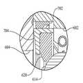
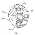
이제 도 26 내지 도 29로 되돌아가면, 일 실시예에서, IVT(600)는 맞물림 해제 메커니즘(700)이 구비될 수 있다. 맞물림 해제 메커니즘(700)은 다른 타입의 변속기들과 사용될 수 있으며 일 예로서 IVT(600)와 함께 여기에서 도시된다. 일 실시예에서, 맞물림 해제 메커니즘(700)은 커플링 링(704)에 결합되는 외부 링(702)을 포함한다. 커플링 링(704)은 견인 링(620)에 부착된다. 몇몇의 실시예들에서, 외부 링(702)과 커플링 링(704)은 그라인딩된 링(625)을 대체한다. 외부 링(702)은 하우징(602)과 하우징 캡(604)에 결합된다. 몇몇의 실시예들에서, 액추에이터(도시되지 않음)는 외부 링(702)에 결합된다. 예를 들면, 액추에이터는 하우징(602)을 통해 연장되고 그에 의해 외부 링(702)이 회전되게 하는 레버(도시되지 않음)일 수 있다. 외부 링(702)은 내주의 주위에 다수의 램프들(706)이 구비된다. 램프들(706)은 내부 링(704)의 외주면의 위에 형성되는 스플라인들(708)의 세트에 결합된다. IVT(600)의 작동 중에, 출력으로부터 입력의 분리는 외부 링(702)을 회전시킴으로써 달성될 수 있다. 외부 링(702)의 회전은 견인 유성 어셈블리들(614)로부터 견인 링(620)의 축방향 이동에 상응한다.Turning now to FIGS. 26-29, in one embodiment, the
이제 도 29 내지 도 30으로 가면, 일 실시예에서, IVT(600)는 맞물림 해제 메커니즘(800)이 구비될 수 있다. 맞물림 해제 메커니즘(800)은 다른 타입의 변속기들과 사용될 수 있으며 일 예로서 IVT(600)와 함께 여기에서 도시된다. 몇몇의 실시예들에서, 맞물림 해제 메커니즘(800)은 커플링(806)을 사용하여 출력 샤프트(804)에 선택적으로 결합될 수 있는 구동 샤프트(802)를 가진다. 일단 조립되면 구동 샤프트(802)와 출력 샤프트(804)는 출력 샤프트(627)의 대신에 사용될 수 있다. 커플링(806)은 출력 샤프트(804)의 내부 직경의 위에 형성되는 스플라인들(808)의 세트를 맞물도록 구성된다. 몇몇의 실시예들에서, 스프링(도시되지 않음)은 커플링과 출력 샤프트(804) 사이에 삽입될 수 있다. 스프링은 맞물리는 위치인, 도 29에 도시된 위치로 커플링(806)을 편향시키는 경향이 있다. 커플링(806)은 케이블 풀(cable pull, 810)에 부착된다. 케이블 풀(810)은 베어링(812)에 의해 커플링(806)의 내부 구멍에 지지될 수 있다. 케이블 풀(810)은 푸시-풀 케이블(도시되지 않음)에 부착될 수 있다. 케이블은 케이블에 장력을 가하고 축방향으로 커플링(806)을 이동시키기 위해 작동될 수 있는 외부 링크장치에 결합될 수 있다. 케이블 가이드(814)는 케이블이 간섭 없이 출력 샤프트(814)의 내부 구멍으로 들어갈 수 있는 통로를 제공한다. 케이블 가이드(814)는 베어링(816)으로 지지된다. IVT(600)의 작동 중에, 출력 샤프트(804)는 케이블(도시되지 않음)에 장력을 가하고 커플링(806)을 축방향으로 이동시킴으로써, 도 30에 도시된 바와 같이, 맞물리는 위치에 선택적으로 결합될 수 있다.Referring now to FIGS. 29-30, in one embodiment, the
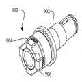
이제 도 31 내지 도 34를 참조하면, 일 실시예에서, IVT(600)는 맞물림 해제 메커니즘(900)이 구비될 수 있다. 맞물림 해제 메커니즘(900)은 다른 타입의 변속기들과 사용될 수 있으며 일 예로서 IVT(600)와 함께 여기에서 도시된다. 일 실시예에서, 맞물림 해제 메커니즘(900)은 출력 샤프트(627)를 대체할 수 있다. 맞물림 해제 메커니즘(900)은 베어링들(628, 629) 및 시일(630)에 의해 하우징(602)에 지지되도록 적절하게 구성되는 가늘고 긴 샤프트(902)를 포함할 수 있다. 가늘고 긴 샤프트(902)는 제1 단부(901)와 제2 단부(903)를 가질 수 있다. 제1 단부(901)는, 예를 들면, 키홈 또는 다른 고정 수단으로 출력 부하장치에 결합되도록 구성될 수 있다. 샤프트(902)의 제2 단부(903)는 다수의 후퇴 가능한 치형들(retractable teeth, 904)이 구비된다. 후퇴 가능한 치형들(904)은 단부(903)의 원주의 둘레에 반경방향으로 배치된다. 후퇴 가능한 치형들(904)은 단부(903)의 위에 형성되는 축방향 연장부들(906) 사이에 삽입될 수 있으며, 이들에 의해 유지될 수 있다. 후퇴 가능한 치형들(904)은 슬라이딩 부재(908)에 작동 가능하게 결합된다. 슬라이딩 부재(908)는 액추에이터 커플링(910)에 결합된다. 슬라이딩 부재(908)는 맞물리는 위치 또는 맞물림이 해제되는 위치로 후퇴 가능한 치형들(904)을 안내한다. 일 실시예에서, 후퇴 가능한 치형들(904)은 도 31 및 32에 도시된 위치로 후퇴 가능한 치형들(904)을 편향시키도록 구성되는 스프링 부재(도시되지 않음)에 결합될 수 있다. 이런 위치에서, 후퇴 가능한 치형들(904)은, 예를 들면, 출력 드라이버(626)를 맞물 수 있다. 액추에이터(도시되지 않음)는 슬라이딩 부재(908)의 이동을 용이하게 하고 이에 대응하여 도 33 및 34에 도시된 제2 위치로 치형들(904)을 이동시키기 위해 샤프트(902)의 내부 구멍을 통해 액추에이터 커플링(910)에 결합되도록 구성될 수 있다. 이 위치에서, 치형들(904)은 반경방향으로 이동되고 그 결과로 출력 드라이버(626)는 샤프트(902)로부터 분리된다.Referring now to FIGS. 31-34, in one embodiment, the
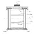
이제 도 35로 되돌아가면, 일 실시예에서, 유압 시스템(950)이 IVT(100), IVT(600), 또는 변속기들의 다른 실시예들과 사용될 수 있다. 유압 시스템(950)은 충전 깊이(954)를 가지는 섬프(sump, 952)를 포함한다. 몇몇의 실시예들에서, 섬프(952)는, 예를 들면, 하우징(602)의 하부에 형성된다. 설명을 위해, IVT(600)의 회전 구성요소들이 도 35에서 회전 구성요소(955)로서 도시된다. 유압 시스템(950)은, 예를 들면, 펌프 어셈블리(635)와 대체로 유사할 수 있는 펌프(956)를 포함한다. 펌프(956)는 섬프(952)로부터 저장소(958)로 유체를 이송시킨다. 일 실시예에서, 저장소(958)는 제1 오리피스(960)와 제2 오리피스(962)가 구비된다. 제1 오리피스(960)는 제2 오리피스(960)의 위에 배치된다. 저장소(958)는 회전 구성요소들(955)과 섬프(952)의 위에 위치된다. 일 실시예에서, 저장소(958)는, 예를 들면, 하우징(602)의 위에 형성될 수 있다. 다른 실시예들에서, 저장소(958)는 하우징(602)의 외측에 부착되며 회전 구성요소들(958) 및 섬프(952)와 유체로 연통되도록 구성된다.Returning now to FIG. 35, in one embodiment, the
IVT(600)의 조립 중에, 예를 들면, 유체가 섬프(952)에 추가된다. 몇몇의 실시예들에서, 섬프(952)의 체적은 작을 수 있으며, 그러므로 섬프(952)에 추가된 유체 체적의 변동은 충전 깊이(954)에 상당한 영향을 끼칠 수 있다. 몇몇 경우에, 충전 깊이(954)는 섬프(952)에 있는 유체가 회전 구성요소들(955)과 접촉하게 하도록 충분히 클 수 있다. 섬프(952)에 있는 유체와 회전 구성요소들(955) 사이의 접촉은 문제가 되는 것으로 알려진, 드래그와 윈디지(windage)를 생성할 수 있다. 그러나, 몇몇의 경우에, 섬프(952)에 추가된 유체의 체적을 증가시키는 것이 바람직할 수 있다. 예를 들면, 유체의 체적의 증가는 열적 특성, 내구성, 및 유지관리를 개선시킬 수 있다. 그러므로, 유압 시스템(952)은 섬프(952)에 추가되는 유체 체적의 증가를 용이하게 하고 충전 깊이(954)를 회전 구성요소들(955)의 아래에 유지하기 위해 실행될 수 있다.During assembly of the
IVT(600)의 작동 중에, 예를 들면, 유체는 펌프(956)에 의해 섬프(952)로부터 배출되며, 이는 충전 깊이(954)를 낮춘다. 유체는 펌프(956)에 의해 가압되며 저장소(958)로 전달된다. 저장소(958)는 가압된 유체를 받아들이고 저장소(958)의 체적을 채운다. 제1 및 제2 오리피스들(960, 962)은 저장소(958)가 압력하에 있으면 유체가 제1 오리피스(960)로부터 흘러나올 수 있지만 유체는 제2 오리피스(962)로부터 실질적으로 흘러나오지 않도록 적절한 크기로 만들어진다. 몇몇의 실시예들에서, 제2 오리피스(962)는 저장소(958)가 감압될 때 개방되고 저장소(958)가 가압될 때 폐쇄되도록 구성되는 체크 밸브일 수 있다. 제1 오리피스(960)로부터의 유체 유동은 윤활과 냉각을 제공하기 위해 회전 구성요소들(955)로 유도된다. IVT(600)의 작동 중에, 예를 들면, 저장소(958)는 일정 체적의 유체를 축적한다. 일단 IVT(600)의 작동이 중지되면, 축적된 체적은 저장소(958)로부터 배출되며 섬프(952)로 반송된다.During operation of
이제 도 36 내지 도 38을 참조하면, 일 실시예에서, IVT(1000)는 IVT(100)와 대체로 유사할 수 있다. 명료성을 위해, IVT(1000)의 오직 몇몇의 내부 구성요소들만이 도시된다. 일 실시예에서, IVT(1000)는 길이방향 축(1002)의 주위에 각도를 이루어 배치되는 다수의 볼들(1001)을 포함한다. 각각의 볼(1001)은 틸팅 가능한 축을 형성하는 유성 액슬(1003)을 중심으로 회전되도록 구성된다. 유성 액슬(1003)의 일 단부는 구형의 롤러(1004)가 구비된다. 유성 액슬(1003)의 반대쪽 단부는, 예를 들면, 핀(1010)으로 가이드 블록(1005)에 결합된다. 일 실시예에서, 가이드 블록(1005)은 연장부(1006)를 가진다. IVT(1000)는 캐리어 부재(118)와 대체로 유사한 제1 캐리어 부재(1007)를 포함할 수 있다. 제1 캐리어 부재(1007)는 적당한 자유도를 가지는 유성 액슬들(1003)을 제공하기 위해 구형 롤러들(1004)에 결합되도록 구성된다. IVT(1000)는 가이드 블록들(1005)에 작동 가능하게 결합되도록 구성되는 제2 캐리어 부재(1008)를 포함할 수 있다. IVT(100)는 제1 및 제2 캐리어 부재들(1007, 1008)과 동축상으로 배치되는 시프팅 플레이트(1012)가 구비된다. 시프팅 플레이트(1012)는 연장부들(1006)에 결합된다. 일 실시예에서, 시프팅 플레이트(1012)는, 예를 들면, 시프트 제어 메커니즘(140)으로 작동될 수 있다. 시프팅 플레이트(1012)는 제1 및 제2 캐리어 부재들(1007, 1008)에 대하여 회전되도록 구성된다.Referring now to FIGS. 36-38, in one embodiment, the
이제 도 38을 구체적으로 참조하면, 일 실시예에서, 시프팅 플레이트(1012)는 다수의 슬롯들(1014)이 구비된다. 연장부들(1006)은 슬롯들(1014)에 결합된다. 설명을 위해, 슬롯들(1014) 중의 하나만이 도시된다. 슬롯(1014)은 세 개의 부분들을 가지는 것으로 도시될 수 있다: 제1 부분(1015), 중간 부분(1016), 및 제3 부분(1017). 중간 부분(1016)은 반경방향 작도 라인들(1018, 1019)의 세트 사이의 호 길이로서 정의될 수 있다. 제1 부분(1015)과 제3 부분(1017)은, 반경방향으로 편향된 가이드 슬롯들(174)이 반경방향 작도 라인(76)으로부터 편향되는 것과 대체로 유사한 방식으로, 반경방향 작도 라인들(1018, 1019) 각각으로부터 각도상으로 편향된다. IVT(1000)의 작동 중에, 변속 비율의 변화는 제1 및 제2 캐리어 부재들(1007, 1008)에 대해 시프팅 플레이트(1012)를 회전시킴으로써 달성될 수 있다. 연장부들(1006)은 슬롯들(1014)에 의해 안내된다. 연장부(1006)가 슬롯(1014)의 제1 부분(1015)에 배치될 때, 변속 비율은 포워드 또는 양의 비율일 수 있다. 연장부(1006)는 슬롯(1014)의 제3 부분(1017)에 배치될 때, 변속 비율은 리버스 또는 음의 비율일 수 있다. 연장부(1006)는 중간 부분(1016)에 배치될 때, 변속 비율은 뉴트럴이거나 "파워 0" 으로 언급된 상태이다. 슬롯(1014)의 치수는 변속 비율의 변화와, 예를 들면, 액추에이터 위치의 변화 사이의 원하는 관계를 수용하기 위해 적절한 크기로 만들어질 수 있다.Referring now specifically to FIG. 38, in one embodiment, the shifting
위의 설명이 특정한 구성요소들 또는 서브어셈블리들에 대한 치수들을 제공하였다는 것이 주목되어야 한다. 언급된 치수들 또는 치수들의 범위는 최선의 형태와 같은 특정한 법률 요건을 가능한 한 최대로 따르도록 제공된다. 그러나, 여기에서 설명된 본 발명의 범위는 오직 청구항들의 언어에 의해서만 결정되어야 하며, 결과적으로, 임의의 하나의 청구항이 특정 치수, 또는 이의 범위, 청구항의 특성을 만드는 경우를 제외하고는, 언급된 치수들은 본 발명의 실시예들에 대한 제한으로 간주되지 않아야 한다.It should be noted that the above description provided the dimensions for specific components or subassemblies. The stated dimensions or range of dimensions are provided to comply with specific legal requirements as best as possible. However, the scope of the invention described herein should be determined only by the language of the claims, and consequently, unless any one claim makes any particular dimension, or range, or characteristics of the claims, as mentioned Dimensions should not be considered as a limitation on the embodiments of the present invention.
앞의 설명은 본 발명의 특정한 실시예들을 상술한다. 그러나, 상술한 것이 아무리 상세하게 본문에 나타난다고 하더라도, 본 발명은 많은 방식으로 실행될 수 있다는 것이 인정될 것이다. 또한 위에서 언급된 바와 같이, 본 발명의 특정한 특징들 또는 양상들을 설명할 때 특정 용어의 사용이 이 용어가 용어와 관련된 본 발명의 특징들 또는 양상들의 임의의 특정한 특징들을 포함하는 것에 제한되도록 여기서 다시 한정되는 것을 의미하기 위해 취해져서는 안 된다는 것이 주목되어야 한다.The foregoing description details certain embodiments of the invention. However, it will be appreciated that the present invention may be practiced in many ways, no matter how detailed the above appears in the text. As also mentioned above, the use of certain terms in describing particular features or aspects of the present invention is here again contemplated so that the term is limited to including any particular features of the features or aspects of the present invention with respect to the term. It should be noted that it should not be taken to mean limiting.
Claims (12)
Translated fromKorean각각의 견인 유성 어셈블리는 틸팅 가능한 액슬을 포함하고, 각각의 틸팅 가능한 액슬의 제1 단부를 안내하도록 구성된 복수의 제1 가이드 슬롯을 구비한 제1 캐리어 부재와, 견인 유성 어셈블리들의 각각의 틸팅 가능한 액슬의 제2 단부를 안내하도록 구성된 복수의 제2 가이드 슬롯을 구비한 제2 캐리어 부재를 포함하며, 상기 제1 및 제2 캐리어 부재는 길이방향 축을 중심으로 회전 가능하며,
상기 맞물림 해제 메커니즘은,
상기 제1 견인 링에 부착되고, 복수의 스플라인들을 포함하는 커플링 링과,
하우징에 결합되며, 상기 복수의 스플라인들에 결합하도록 구성된 복수의 램프들을 구비한 외부 링을 포함하고,
상기 외부 링의 상기 커플링 링에 대한 회전은 입력 파워 인터페이스를 출력 파워 인터페이스로부터 분리시키는 맞물림 해제 메커니즘.An engagement mechanism of an infinitely variable transmission (IVT) disposed at an angle about a longitudinal axis and comprising a plurality of traction planetary assemblies interposed between the first and second traction rings,
Each traction planetary assembly includes a tiltable axle, a first carrier member having a plurality of first guide slots configured to guide a first end of each tiltable axle, and each tiltable axle of the traction planetary assemblies. A second carrier member having a plurality of second guide slots configured to guide a second end of the first carrier member, the first and second carrier members being rotatable about a longitudinal axis;
The disengagement mechanism is
A coupling ring attached to the first traction ring and including a plurality of splines;
An outer ring coupled to the housing and having a plurality of lamps configured to couple to the plurality of splines,
Rotation of the outer ring about the coupling ring separates an input power interface from an output power interface.
상기 외부 링은 상기 하우징과 하우징 캡에 결합하는 맞물림 해제 메커니즘.The method of claim 1,
And the outer ring engages the housing and the housing cap.
상기 외부 링에 결합된 액추에이터를 더 포함하는 맞물림 해제 메커니즘.The method of claim 2,
And an actuator coupled to the outer ring.
상기 액추에이터는 레버를 포함하는 맞물림 해제 메커니즘.The method of claim 3,
And the actuator includes a lever.
상기 외부 링의 회전은 상기 입력 파워 인터페이스를 상기 출력 파워 인터페이스로부터 분리하기 위해 상기 복수의 견인 유성 어셈블리들로부터의 상기 제1 견인 링의 축 방향 변위에 상응하는 맞물림 해제 메커니즘.The method of claim 1,
Rotation of the outer ring corresponds to an axial displacement of the first traction ring from the plurality of traction planetary assemblies to separate the input power interface from the output power interface.
회전 파워 소스(a source of rotational power)에 연결된 입력 파워 인터페이스와,
길이방향 축을 중심으로 각을 이루어 배치되고 제1 견인 링과 제2 견인 링 사이에 개재된 복수의 견인 유성 어셈블리들로서, 각각의 견인 유성 어셈블리는 틸팅 가능한 액슬을 포함하는 복수의 견인 유성 어셈블리들과,
복수의 제1 가이드 슬롯들을 포함하며, 상기 견인 유성 어셈블리들의 각각의 틸팅 가능한 액슬의 제1 단부를 안내하도록 구성된 제1 캐리어 부재와,
복수의 제2 가이드 슬롯들을 포함하며, 상기 견인 유성 어셈블리들의 각각의 틸팅 가능한 액슬의 제2 단부를 안내하도록 구성된 제2 캐리어 부재와,
상기 제1 견인 링으로부터 입력 파워 소스(an input power source)를 분리하도록 구성된 맞물림 해제 메커니즘을 더 포함하고,
상기 맞물림 해제 메커니즘은,
상기 제1 견인 링에 부착되고, 복수의 스플라인들을 포함하는 커플링 링과,
하우징에 결합되며, 상기 복수의 스플라인들에 결합하도록 구성된 복수의 램프들을 구비한 외부 링을 포함하고,
상기 제1 캐리어 부재 및 상기 제2 캐리어 부재 중 적어도 하나는 상기 입력 파워 인터페이스로부터 회전 파워 입력(a rotational power input)을 받으며, 상기 제1 캐리어 부재는 상기 제2 캐리어 부재에 대해 회전할 수 있으며,
상기 외부 링의 회전은 상기 제1 견인 링의 상기 복수의 견인 유성 어셈블리들로부터의 축방향 변위를 유발하는 무한 가변 변속기.An infinitely variable transmission (IVT) comprising a main shaft located along a longitudinal axis,
An input power interface connected to a source of rotational power,
A plurality of towing planetary assemblies disposed at an angle about the longitudinal axis and interposed between the first towing ring and the second towing ring, each towing planetary assembly comprising a plurality of towing planetary assemblies comprising a tiltable axle;
A first carrier member comprising a plurality of first guide slots, the first carrier member configured to guide a first end of the tiltable axle of each of the traction planetary assemblies;
A second carrier member comprising a plurality of second guide slots, the second carrier member configured to guide a second end of the tiltable axle of each of the traction planetary assemblies;
Further comprising an disengagement mechanism configured to separate an input power source from the first tow ring;
The disengagement mechanism is
A coupling ring attached to the first traction ring and including a plurality of splines;
An outer ring coupled to the housing and having a plurality of lamps configured to couple to the plurality of splines,
At least one of the first carrier member and the second carrier member receives a rotational power input from the input power interface, the first carrier member may rotate relative to the second carrier member,
Rotation of the outer ring causes an axial displacement from the plurality of traction planetary assemblies of the first traction ring.
상기 메인 샤프트는 상기 제1 캐리어 부재에 결합된 무한 가변 변속기.The method of claim 6,
The main shaft is coupled to the first carrier member.
상기 메인 샤프트는 상기 제1 캐리어 부재와 제2 캐리어 부재에 결합된 무한 가변 변속기.The method of claim 7, wherein
And the main shaft is coupled to the first carrier member and the second carrier member.
상기 제1 캐리어 부재와 제2 캐리어 부재는 상기 메인 샤프트로부터 회전 파워(rotational power)를 받는 무한 가변 변속기.The method of claim 8,
And the first carrier member and the second carrier member receive rotational power from the main shaft.
상기 무한 가변 변속기는,
회전 파워 소스에 연결된 입력 파워 인터페이스와,
길이방향 축을 중심으로 각을 이루어 배치되고 제1 견인 링과 제2 견인 링 사이에 개재된 복수의 견인 유성 어셈블리들로서, 각각의 견인 유성 어셈블리는 틸팅 가능한 액슬을 포함하는 복수의 견인 유성 어셈블리들과,
복수의 제1 가이드 슬롯들을 포함하며, 상기 견인 유성 어셈블리들의 각각의 틸팅 가능한 액슬의 제1 단부를 안내하도록 구성된 제1 캐리어 부재와,
복수의 제2 가이드 슬롯들을 포함하며, 상기 견인 유성 어셈블리들의 각각의 틸팅 가능한 액슬의 제2 단부를 안내하도록 구성된 제2 캐리어 부재를 포함하며,
상기 방법은,
하우징에 결합된 외부 링을 회전시키는 단계를 포함하며,
상기 외부 링은 내주에 형성된 복수의 램프들을 포함하며, 상기 복수의 램프들은 상기 제1 견인 링에 결합된 내부 링의 외주에 형성된 한 세트의 스플라인들에 결합되고,
상기 외부 링의 회전은 상기 제1 견인 링의 상기 복수의 견인 유성 어셈블리들로부터의 축 방향 변위에 상응하는 방법.A method of separating input power or output rod from an infinitely variable transmission (IVT) comprising a main shaft located along a longitudinal axis,
The infinitely variable transmission,
An input power interface connected to a rotating power source,
A plurality of towing planetary assemblies disposed at an angle about the longitudinal axis and interposed between the first towing ring and the second towing ring, each towing planetary assembly comprising a plurality of towing planetary assemblies comprising a tiltable axle;
A first carrier member comprising a plurality of first guide slots, the first carrier member configured to guide a first end of the tiltable axle of each of the traction planetary assemblies;
A second carrier member comprising a plurality of second guide slots, the second carrier member configured to guide a second end of the tiltable axle of each of the traction planetary assemblies,
The method,
Rotating an outer ring coupled to the housing;
The outer ring includes a plurality of lamps formed at an inner circumference, the plurality of lamps are coupled to a set of splines formed at an outer circumference of the inner ring coupled to the first traction ring,
Rotation of the outer ring corresponds to axial displacement from the plurality of traction planetary assemblies of the first traction ring.
상기 외부 링은 상기 제1 견인 링에 결합되며, 상기 입력 파워 인터페이스는 상기 제1 견인 링으로부터 분리되는 방법.The method of claim 10,
The outer ring is coupled to the first traction ring, and the input power interface is separated from the first traction ring.
Applications Claiming Priority (3)
| Application Number | Priority Date | Filing Date | Title |
|---|---|---|---|
| US31022410P | 2010-03-03 | 2010-03-03 | |
| US61/310,224 | 2010-03-03 | ||
| PCT/US2011/026756WO2011109444A1 (en) | 2010-03-03 | 2011-03-01 | Infinitely variable transmissions, continuously variable transmissions, methods, assemblies, subassemblies, and components therefor |
Related Parent Applications (1)
| Application Number | Title | Priority Date | Filing Date |
|---|---|---|---|
| KR1020177030044ADivisionKR101906331B1 (en) | 2010-03-03 | 2011-03-01 | Infinitely variable transmissions, continuously variable transmissions, methods, assemblies, subassemblies, and components therefor |
Publications (2)
| Publication Number | Publication Date |
|---|---|
| KR20180110215A KR20180110215A (en) | 2018-10-08 |
| KR102021255B1true KR102021255B1 (en) | 2019-09-11 |
Family
ID=43974808
Family Applications (3)
| Application Number | Title | Priority Date | Filing Date |
|---|---|---|---|
| KR1020177030044AExpired - Fee RelatedKR101906331B1 (en) | 2010-03-03 | 2011-03-01 | Infinitely variable transmissions, continuously variable transmissions, methods, assemblies, subassemblies, and components therefor |
| KR1020187028034AActiveKR102021255B1 (en) | 2010-03-03 | 2011-03-01 | Infinitely variable transmissions, continuously variable transmissions, methods, assemblies, subassemblies, and components therefor |
| KR1020127025783AExpired - Fee RelatedKR101791012B1 (en) | 2010-03-03 | 2011-03-01 | Infinitely variable transmissions, continuously variable transmissions, methods, assemblies, subassemblies, and components therefor |
Family Applications Before (1)
| Application Number | Title | Priority Date | Filing Date |
|---|---|---|---|
| KR1020177030044AExpired - Fee RelatedKR101906331B1 (en) | 2010-03-03 | 2011-03-01 | Infinitely variable transmissions, continuously variable transmissions, methods, assemblies, subassemblies, and components therefor |
Family Applications After (1)
| Application Number | Title | Priority Date | Filing Date |
|---|---|---|---|
| KR1020127025783AExpired - Fee RelatedKR101791012B1 (en) | 2010-03-03 | 2011-03-01 | Infinitely variable transmissions, continuously variable transmissions, methods, assemblies, subassemblies, and components therefor |
Country Status (12)
| Country | Link |
|---|---|
| US (5) | US8512195B2 (en) |
| EP (2) | EP2542800B1 (en) |
| JP (2) | JP5819863B2 (en) |
| KR (3) | KR101906331B1 (en) |
| CN (2) | CN102869900B (en) |
| BR (1) | BR112012022240A8 (en) |
| CA (1) | CA2791307C (en) |
| MX (1) | MX2012010016A (en) |
| PL (1) | PL3021004T3 (en) |
| RU (1) | RU2584635C2 (en) |
| TW (3) | TWI622520B (en) |
| WO (1) | WO2011109444A1 (en) |
Families Citing this family (63)
| Publication number | Priority date | Publication date | Assignee | Title |
|---|---|---|---|---|
| US7011600B2 (en) | 2003-02-28 | 2006-03-14 | Fallbrook Technologies Inc. | Continuously variable transmission |
| WO2006041718A2 (en) | 2004-10-05 | 2006-04-20 | Fallbrook Technologies, Inc. | Continuously variable transmission |
| WO2007070167A2 (en) | 2005-10-28 | 2007-06-21 | Fallbrook Technologies Inc. | Electromotive drives |
| PL1954959T3 (en) | 2005-11-22 | 2013-10-31 | Fallbrook Ip Co Llc | Continuously variable transmission |
| CN102221073B (en) | 2005-12-09 | 2013-03-27 | 福博科技术公司 | Continuously variable transmission |
| EP1811202A1 (en) | 2005-12-30 | 2007-07-25 | Fallbrook Technologies, Inc. | A continuously variable gear transmission |
| US7882762B2 (en) | 2006-01-30 | 2011-02-08 | Fallbrook Technologies Inc. | System for manipulating a continuously variable transmission |
| CN102269055B (en) | 2006-06-26 | 2013-08-28 | 福博科技术公司 | Continuously variable transmission |
| PL2089642T3 (en) | 2006-11-08 | 2013-09-30 | Fallbrook Ip Co Llc | Clamping force generator |
| EP2125469A2 (en) | 2007-02-01 | 2009-12-02 | Fallbrook Technologies Inc. | System and methods for control of transmission and/or prime mover |
| US20100093479A1 (en) | 2007-02-12 | 2010-04-15 | Fallbrook Technologies Inc. | Continuously variable transmissions and methods therefor |
| TWI461615B (en) | 2007-02-16 | 2014-11-21 | Fallbrook Ip Co Llc | Infinitely variable transmissions, continuously variable transmissions, methods, assemblies, subassemblies, and components therefor |
| EP2142826B1 (en) | 2007-04-24 | 2015-10-28 | Fallbrook Intellectual Property Company LLC | Electric traction drives |
| US8641577B2 (en) | 2007-06-11 | 2014-02-04 | Fallbrook Intellectual Property Company Llc | Continuously variable transmission |
| CN103697120B (en) | 2007-07-05 | 2017-04-12 | 福博科技术公司 | Continuously variable transmission |
| CN103939602B (en) | 2007-11-16 | 2016-12-07 | 福博科知识产权有限责任公司 | Controllers for variable speed drives |
| US8321097B2 (en) | 2007-12-21 | 2012-11-27 | Fallbrook Intellectual Property Company Llc | Automatic transmissions and methods therefor |
| US8313405B2 (en) | 2008-02-29 | 2012-11-20 | Fallbrook Intellectual Property Company Llc | Continuously and/or infinitely variable transmissions and methods therefor |
| US8317651B2 (en) | 2008-05-07 | 2012-11-27 | Fallbrook Intellectual Property Company Llc | Assemblies and methods for clamping force generation |
| CN102112778B (en) | 2008-06-06 | 2013-10-16 | 福博科技术公司 | Infinitely variable transmission, continuously variable transmission, methods, assemblies, subassemblies and components therefor |
| EP2304272B1 (en) | 2008-06-23 | 2017-03-08 | Fallbrook Intellectual Property Company LLC | Continuously variable transmission |
| CA2732668C (en) | 2008-08-05 | 2017-11-14 | Fallbrook Technologies Inc. | Methods for control of transmission and prime mover |
| US8469856B2 (en) | 2008-08-26 | 2013-06-25 | Fallbrook Intellectual Property Company Llc | Continuously variable transmission |
| US8167759B2 (en) | 2008-10-14 | 2012-05-01 | Fallbrook Technologies Inc. | Continuously variable transmission |
| US9464701B2 (en)* | 2009-01-22 | 2016-10-11 | Orbital Traction, Ltd. | Fluid movement systems including a continuously variable transmission |
| ES2439647T3 (en) | 2009-04-16 | 2014-01-24 | Fallbrook Intellectual Property Company Llc | Stator set and speed change mechanism for a continuously variable transmission |
| US8512195B2 (en) | 2010-03-03 | 2013-08-20 | Fallbrook Intellectual Property Company Llc | Infinitely variable transmissions, continuously variable transmissions, methods, assemblies, subassemblies, and components therefor |
| US8888643B2 (en) | 2010-11-10 | 2014-11-18 | Fallbrook Intellectual Property Company Llc | Continuously variable transmission |
| AU2012240435B2 (en) | 2011-04-04 | 2016-04-28 | Fallbrook Intellectual Property Company Llc | Auxiliary power unit having a continuously variable transmission |
| EP2719923A4 (en)* | 2011-06-10 | 2016-03-02 | Toyota Motor Co Ltd | TRANSMISSION WITH CONTINUOUS VARIATION |
| EP2764305A2 (en)* | 2011-10-03 | 2014-08-13 | Fallbrook Intellectual Property Company LLC | Refrigeration system having a continuously variable transmission |
| CN104302949B (en)* | 2012-01-23 | 2017-05-03 | 福博科知识产权有限责任公司 | Infinitely variable continuously variable transmission, continuously variable continuously variable transmission, method, assembly, subassembly, and parts thereof |
| BR112014027447A2 (en)* | 2012-05-02 | 2017-06-27 | Parker Hannifin Corp | transmission and hydromechanical assemblies |
| US20140219598A1 (en)* | 2012-10-02 | 2014-08-07 | Andrew P. Grosskopf | Variable frequency generator input shaft bearing |
| US9429217B2 (en) | 2013-01-28 | 2016-08-30 | Robert Hornblower Meyer | Continuously variable drive mechanism |
| WO2014142822A1 (en)* | 2013-03-13 | 2014-09-18 | Allison Transmission Inc. | Final drive disconnect mechanism |
| US9322461B2 (en)* | 2013-03-14 | 2016-04-26 | Team Industries, Inc. | Continuously variable transmission with input/output planetary ratio assembly |
| KR102433297B1 (en) | 2013-04-19 | 2022-08-16 | 폴브룩 인텔렉츄얼 프로퍼티 컴퍼니 엘엘씨 | Continuously variable transmission |
| US10012304B2 (en)* | 2013-05-07 | 2018-07-03 | Transmission Cvtcorp Inc. | Continuously variable transmission provided with a gerotor pump |
| CN103600805B (en)* | 2013-10-28 | 2016-02-24 | 南通雷圣特种电机有限公司 | The dynamic structure of novel assisted electric bicycle |
| DE102014221514A1 (en)* | 2014-10-23 | 2016-04-28 | Robert Bosch Gmbh | Adjustable friction-ring gearbox for a motor-powered and / or pedal-operated vehicle |
| WO2016148721A1 (en)* | 2015-03-19 | 2016-09-22 | Allison Transmission, Inc. | Variator stator functional and manufacturing improvements |
| US10400872B2 (en) | 2015-03-31 | 2019-09-03 | Fallbrook Intellectual Property Company Llc | Balanced split sun assemblies with integrated differential mechanisms, and variators and drive trains including balanced split sun assemblies |
| CN105276110B (en)* | 2015-07-29 | 2017-05-31 | 四川大学 | One kind is without the towed buncher that spins |
| JP5885371B1 (en)* | 2015-08-07 | 2016-03-15 | 株式会社エフ・シー・シー | Continuously variable transmission |
| CN105114620B (en)* | 2015-09-18 | 2017-05-10 | 湖南农业大学 | A shift control device for a continuously variable transmission |
| EP3187751B1 (en)* | 2015-12-30 | 2019-03-06 | Rolless GmbH | Infinitely adjustable planetary gear |
| US10047861B2 (en) | 2016-01-15 | 2018-08-14 | Fallbrook Intellectual Property Company Llc | Systems and methods for controlling rollback in continuously variable transmissions |
| WO2017151610A1 (en)* | 2016-03-01 | 2017-09-08 | Dana Limited | Carrier skew shift actuator mechanism for a continuously variable ball planetary transmission having a rotataing carrier |
| KR102364407B1 (en) | 2016-03-18 | 2022-02-16 | 폴브룩 인텔렉츄얼 프로퍼티 컴퍼니 엘엘씨 | continuously variable transmission system and method |
| US10023266B2 (en) | 2016-05-11 | 2018-07-17 | Fallbrook Intellectual Property Company Llc | Systems and methods for automatic configuration and automatic calibration of continuously variable transmissions and bicycles having continuously variable transmissions |
| JP6773297B2 (en)* | 2016-10-14 | 2020-10-21 | 日本電産シンポ株式会社 | Continuously variable transmission and bicycle |
| TWI610038B (en)* | 2017-02-07 | 2018-01-01 | Motive Power Industry Co Ltd | Stepless shifting ring seat drive mechanism |
| TWI648494B (en)* | 2017-02-07 | 2019-01-21 | 摩特動力工業股份有限公司 | Stepless speed change mechanism |
| WO2018187424A1 (en)* | 2017-04-05 | 2018-10-11 | Dana Limited | Passive ratio control methods for a ball-type planetary transmission |
| US10859142B2 (en) | 2017-11-02 | 2020-12-08 | Stephen Douglas Williams | Slip-modulated proprioceptive infinitely variable transmission and robotic power distribution system |
| TWI648491B (en)* | 2017-11-21 | 2019-01-21 | 摩特動力工業股份有限公司 | Coaxial electric power stepless transmission |
| US11215268B2 (en) | 2018-11-06 | 2022-01-04 | Fallbrook Intellectual Property Company Llc | Continuously variable transmissions, synchronous shifting, twin countershafts and methods for control of same |
| CN111219446B (en)* | 2018-11-27 | 2023-01-17 | 富田电机股份有限公司 | Integrated power module of electric locomotive |
| WO2020176392A1 (en) | 2019-02-26 | 2020-09-03 | Fallbrook Intellectual Property Company Llc | Reversible variable drives and systems and methods for control in forward and reverse directions |
| DE102021200929A1 (en) | 2020-02-04 | 2021-08-05 | Dana Heavy Vehicle Systems Group, Llc | PROCEDURES AND SYSTEMS FOR AN ACTUATOR SYSTEM |
| WO2021182001A1 (en) | 2020-03-12 | 2021-09-16 | 住友重機械工業株式会社 | Friction transmission device |
| CN111559458A (en)* | 2020-05-08 | 2020-08-21 | 江苏创斯达科技有限公司 | Rear wheel driving device of power-assisted bicycle |
Citations (1)
| Publication number | Priority date | Publication date | Assignee | Title |
|---|---|---|---|---|
| US20090221391A1 (en) | 2008-02-29 | 2009-09-03 | Fallbrook Technologies Inc. | Continuously and/or infinitely variable transmissions and methods therefor |
Family Cites Families (690)
| Publication number | Priority date | Publication date | Assignee | Title |
|---|---|---|---|---|
| USRE22761E (en)* | 1946-05-28 | Transmission | ||
| GB592320A (en) | 1945-03-13 | 1947-09-15 | Frederick Whigham Mcconnel | Improvements in or relating to variable speed-gears |
| US1121210A (en) | 1914-12-15 | Fried Krupp Germaniawerft Ag | Submarine boat. | |
| US2675713A (en) | 1954-04-20 | Protective mechanism for variable | ||
| US719595A (en)* | 1901-07-06 | 1903-02-03 | Jacob B Huss | Bicycle driving mechanism. |
| US1207985A (en) | 1914-08-17 | 1916-12-12 | Charles I Null | Antifriction-hanger. |
| US1175677A (en)* | 1914-10-24 | 1916-03-14 | Roderick Mcclure | Power-transmitting device. |
| US1380006A (en) | 1917-08-04 | 1921-05-31 | Hamilton Beach Mfg Co | Variable-speed transmission |
| JP3223241B2 (en)* | 1997-03-17 | 2001-10-29 | 本田技研工業株式会社 | Belt type continuously variable transmission |
| US1390971A (en) | 1921-01-24 | 1921-09-13 | Samain Pierre | Gearing |
| US1558222A (en) | 1924-01-14 | 1925-10-20 | Beetow Albert | Backlash take-up for gears |
| CH118064A (en) | 1924-08-07 | 1926-12-16 | Jakob Arter | Friction change transmission. |
| US1629902A (en) | 1924-08-07 | 1927-05-24 | Arter Jakob | Power-transmitting device |
| US1686446A (en) | 1926-04-15 | 1928-10-02 | John A Gilman | Planetary transmission mechanism |
| FR620375A (en) | 1926-06-24 | 1927-04-21 | Automatic pressure device for friction plates | |
| US1774254A (en) | 1927-06-28 | 1930-08-26 | John F Daukus | Clutch mechanism |
| US1903228A (en)* | 1927-10-21 | 1933-03-28 | Gen Motors Corp | Frictional gearing |
| DE498701C (en) | 1927-11-18 | 1930-05-31 | Jakob Arter | Friction ball change gear |
| US1865102A (en) | 1929-05-07 | 1932-06-28 | Frank A Hayes | Variable speed transmission mechanism |
| US1793571A (en)* | 1929-12-14 | 1931-02-24 | Frank O Vaughn | Variable-speed drive |
| US1847027A (en)* | 1930-02-19 | 1932-02-23 | Thomsen Thomas Peter | Change-speed gear |
| US1978439A (en) | 1930-04-01 | 1934-10-30 | John S Sharpe | Variable transmission |
| US1850189A (en)* | 1930-07-16 | 1932-03-22 | Carl W Weiss | Transmission device |
| GB391448A (en) | 1930-08-02 | 1933-04-27 | Frank Anderson Hayes | Improvements in or relating to friction transmission |
| US1858696A (en) | 1931-07-08 | 1932-05-17 | Carl W Weiss | Transmission |
| US2131158A (en) | 1932-02-03 | 1938-09-27 | Gen Motors Corp | Continuously variable transmission |
| US2086491A (en) | 1932-04-11 | 1937-07-06 | Adiel Y Dodge | Variable speed transmission |
| US2109845A (en)* | 1932-07-23 | 1938-03-01 | Erban Operating Corp | Power transmission mechanism |
| US2196064A (en)* | 1933-02-04 | 1940-04-02 | Erban Patents Corp | Driving energy consumer |
| US2060884A (en) | 1933-09-19 | 1936-11-17 | Erban Operating Corp | Power transmission mechanism |
| US2112763A (en)* | 1933-12-28 | 1938-03-29 | Cloudsley John Leslie | Variable speed power transmission mechanism |
| US2030203A (en)* | 1934-05-31 | 1936-02-11 | Gen Motors Corp | Torque loading lash adjusting device for friction roller transmissions |
| US2134225A (en) | 1935-03-13 | 1938-10-25 | Christiansen Ejnar | Variable speed friction gear |
| US2152796A (en)* | 1935-03-13 | 1939-04-04 | Erban Patents Corp | Variable speed transmission |
| US2100629A (en) | 1936-07-18 | 1937-11-30 | Chilton Roland | Transmission |
| US2209254A (en) | 1938-07-29 | 1940-07-23 | Yrjo A Ahnger | Friction transmission device |
| US2259933A (en) | 1939-02-20 | 1941-10-21 | John O Holloway | Clutch coupling for motor vehicles |
| US2325502A (en) | 1940-03-08 | 1943-07-27 | Georges Auguste Felix | Speed varying device |
| US2269434A (en) | 1940-11-18 | 1942-01-13 | Cuyler W Brooks | Automatic transmission mechanism |
| US2595367A (en) | 1943-11-09 | 1952-05-06 | Picanol Jaime | Toroidal variable-speed gear drive |
| US2480968A (en) | 1944-08-30 | 1949-09-06 | Ronai Ernest | Variable transmission means |
| US2469653A (en) | 1945-02-01 | 1949-05-10 | Kopp Jean | Stepless variable change-speed gear with roller bodies |
| US2461258A (en) | 1946-06-06 | 1949-02-08 | Cuyler W Brooks | Automatic transmission mechanism |
| US2596538A (en) | 1946-07-24 | 1952-05-13 | Allen A Dicke | Power transmission |
| US2553465A (en) | 1946-11-30 | 1951-05-15 | Monge Jean Raymond Barthelemy | Manual or power-operated planetary transmission |
| NL82920C (en) | 1948-04-17 | |||
| US2586725A (en) | 1950-02-08 | 1952-02-19 | Roller Gear Corp | Variable-speed transmission |
| US2696888A (en) | 1951-05-26 | 1954-12-14 | Curtiss Wright Corp | Propeller having variable ratio transmission for changing its pitch |
| US2716357A (en) | 1952-07-07 | 1955-08-30 | Rennerfelt Sven Bernhard | Continuously variable speed gears |
| US2730904A (en)* | 1952-07-14 | 1956-01-17 | Rennerfelt Sven Bernhard | Continuously variable speed gears |
| US2748614A (en) | 1953-06-23 | 1956-06-05 | Zenas V Weisel | Variable speed transmission |
| US2901924A (en) | 1954-08-05 | 1959-09-01 | New Prod Corp | Accessory drive |
| US2868038A (en)* | 1955-05-26 | 1959-01-13 | Liquid Controls Corp | Infinitely variable planetary transmission |
| US2873911A (en) | 1955-05-26 | 1959-02-17 | Librascope Inc | Mechanical integrating apparatus |
| US2913932A (en) | 1955-10-04 | 1959-11-24 | Mcculloch Motors Corp | Variable speed planetary type drive |
| US2874592A (en)* | 1955-11-07 | 1959-02-24 | Mcculloch Motors Corp | Self-controlled variable speed planetary type drive |
| US2959063A (en) | 1956-09-11 | 1960-11-08 | Perbury Engineering Ltd | Infinitely variable change speed gears |
| US2891213A (en) | 1956-10-30 | 1959-06-16 | Electric Control Corp | Constant frequency variable input speed alternator apparatuses |
| US2931235A (en) | 1957-11-12 | 1960-04-05 | George Cohen 600 Group Ltd | Variable speed friction drive transmissions |
| US2931234A (en) | 1957-11-12 | 1960-04-05 | George Cohen 600 Group Ltd | Variable speed friction drive trans-mission units |
| US2883883A (en) | 1957-11-13 | 1959-04-28 | Curtiss Wright Corp | Variable speed transmission |
| US2964959A (en) | 1957-12-06 | 1960-12-20 | Gen Motors Corp | Accessory drive transmission |
| DE1171692B (en) | 1958-01-09 | 1964-06-04 | Fabrications Unicum Soc D | Friction gear with several flat friction discs |
| BE574149A (en) | 1958-01-09 | 1959-04-16 | Fabrications Unicum Soc D | Pressure device of friction speed variators |
| US3048056A (en) | 1958-04-10 | 1962-08-07 | Gen Motors Corp | Drive system |
| US3035460A (en) | 1958-12-02 | 1962-05-22 | Guichard Louis | Automatic infinitely variablespeed drive |
| US2959070A (en) | 1959-01-09 | 1960-11-08 | Borg Warner | Accessory drive |
| US2959972A (en) | 1959-02-11 | 1960-11-15 | Avco Mfg Corp | Single ball joint roller support for toroidal variable ratio transmissions |
| US3051020A (en) | 1959-02-16 | 1962-08-28 | Thornton Axle Inc | Locking differential with pressure relief device |
| US3008061A (en) | 1959-04-21 | 1961-11-07 | Barden Corp | Slow speed motor |
| US2949800A (en) | 1959-05-11 | 1960-08-23 | Neuschotz Robert | Tool for installing threaded elements |
| US3248960A (en) | 1959-11-13 | 1966-05-03 | Roller Gear Ltd | Variable speed drive transmission |
| DE1178259B (en) | 1959-12-03 | 1964-09-17 | Motoren Werke Mannheim Ag | Main and secondary connecting rod for V machines |
| US3204476A (en) | 1960-04-05 | 1965-09-07 | William S Rouverol | Variable speed transmission |
| US3237468A (en) | 1960-05-13 | 1966-03-01 | Roller Gear Ltd | Variable speed drive transmission |
| DE1217166B (en) | 1960-11-04 | 1966-05-18 | Manabu Kashihara | Ball friction gear with swiveling balls |
| US3246531A (en) | 1960-11-04 | 1966-04-19 | Kashihara Manabu | Infinitely variable speed change gear |
| BE629125A (en) | 1961-03-08 | |||
| US3229538A (en) | 1961-09-25 | 1966-01-18 | Roller Gear Ltd | Variable speed drive transmission |
| US3154957A (en) | 1961-10-16 | 1964-11-03 | Kashihara Manabu | Infinitely variable speed change gear utilizing a ball |
| US3086704A (en) | 1961-11-24 | 1963-04-23 | Ryan Aeronautical Co | Cosine-secant multiplier |
| CH398236A (en) | 1962-09-20 | 1965-08-31 | Yamamoto Sota | Friction stepless speed variator |
| US3216283A (en) | 1963-03-04 | 1965-11-09 | Ford Motor Co | Variable speed torque transmitting means |
| US3283614A (en) | 1963-04-10 | 1966-11-08 | Gen Motors Corp | Friction drive mechanism |
| US3163050A (en) | 1963-06-19 | 1964-12-29 | Excelermatic | Toroidal transmission bearing means |
| US3211364A (en) | 1963-10-30 | 1965-10-12 | Lau Blower Co | Blower wheel |
| US3184983A (en) | 1963-10-30 | 1965-05-25 | Excelermatic | Toroidal transmission mechanism with torque loading cam means |
| FR1376401A (en) | 1963-12-05 | 1964-10-23 | Fabrications Unicum Soc D | Improvements to the adjustment device of friction speed variators in particular |
| JPS441098Y1 (en) | 1964-12-24 | 1969-01-17 | ||
| JPS422843Y1 (en) | 1965-01-18 | 1967-02-20 | ||
| US3273468A (en) | 1965-01-26 | 1966-09-20 | Fawick Corp | Hydraulic system with regenerative position |
| JPS422844Y1 (en) | 1965-02-06 | 1967-02-20 | ||
| JPS413126Y1 (en) | 1965-08-04 | 1966-02-23 | ||
| US3340895A (en) | 1965-08-27 | 1967-09-12 | Sanders Associates Inc | Modular pressure regulating and transfer valve |
| GB1119988A (en) | 1965-10-14 | 1968-07-17 | Nat Res Dev | Transmission system for interconnecting two rotary machines |
| US3464281A (en) | 1965-10-27 | 1969-09-02 | Hiroshi Azuma | Friction-type automatic variable speed means |
| GB1132473A (en) | 1965-11-15 | 1968-11-06 | James Robert Young | Variable ratio friction transmission and control system therefor |
| US3280646A (en) | 1966-02-02 | 1966-10-25 | Ford Motor Co | Control system for an infinitely variable speed friction drive |
| GB1135141A (en)* | 1966-07-04 | 1968-11-27 | Self Changing Gears Ltd | Improved auxiliary overdrive gear |
| JPS47448B1 (en) | 1966-07-08 | 1972-01-07 | ||
| US3430504A (en) | 1966-08-29 | 1969-03-04 | Gen Motors Corp | Transmission |
| GB1195205A (en) | 1966-09-12 | 1970-06-17 | Nat Res Dev | Improvements in or relating to Toroidal Race Transmission Units. |
| SE316664B (en)* | 1966-11-30 | 1969-10-27 | B Gustavsson | |
| US3407687A (en) | 1967-03-27 | 1968-10-29 | Hayashi Tadashi | Variable ratio power transmission device |
| JPS47962Y1 (en) | 1967-05-09 | 1972-01-14 | ||
| US3477315A (en) | 1967-12-18 | 1969-11-11 | Elmer Fred Macks | Dynamoelectric device with speed change mechanism |
| JPS47448Y1 (en) | 1967-12-27 | 1972-01-10 | ||
| JPS4720535Y1 (en) | 1968-06-14 | 1972-07-10 | ||
| JPS47207Y1 (en) | 1968-06-24 | 1972-01-07 | ||
| JPS4912742Y1 (en) | 1968-12-18 | 1974-03-28 | ||
| JPS4729762Y1 (en) | 1969-03-03 | 1972-09-06 | ||
| US3574289A (en) | 1969-05-06 | 1971-04-13 | Gen Motors Corp | Transmission and control system |
| US3581587A (en) | 1969-05-06 | 1971-06-01 | Gen Motors Corp | Transmission |
| BE732960A (en) | 1969-05-13 | 1969-10-16 | ||
| JPS4912742B1 (en)* | 1969-10-15 | 1974-03-27 | ||
| JPS4941536B1 (en) | 1969-11-27 | 1974-11-09 | ||
| NL7004605A (en) | 1970-04-01 | 1971-10-05 | ||
| US3707888A (en) | 1970-07-31 | 1973-01-02 | Roller Gear Ltd | Variable speed transmission |
| JPS4913823Y1 (en) | 1970-10-31 | 1974-04-05 | ||
| US3695120A (en) | 1971-01-14 | 1972-10-03 | Georg Titt | Infinitely variable friction mechanism |
| CH534826A (en) | 1971-02-18 | 1973-03-15 | Zuercher Andre | Friction gear |
| US3727473A (en) | 1971-04-14 | 1973-04-17 | E Bayer | Variable speed drive mechanisms |
| JPS5235481Y2 (en) | 1971-05-13 | 1977-08-12 | ||
| US3727474A (en) | 1971-10-04 | 1973-04-17 | Fullerton Transiission Co | Automotive transmission |
| JPS5032867Y2 (en) | 1971-10-21 | 1975-09-25 | ||
| JPS5125903B2 (en) | 1971-11-13 | 1976-08-03 | ||
| US3768715A (en) | 1972-05-01 | 1973-10-30 | Bell & Howell Co | Planetary differential and speed servo |
| JPS4941536U (en) | 1972-07-14 | 1974-04-12 | ||
| JPS5348166Y2 (en) | 1972-07-29 | 1978-11-17 | ||
| US3802284A (en) | 1972-08-02 | 1974-04-09 | Rotax Ltd | Variable-ratio toric drive with hydraulic relief means |
| US3987681A (en) | 1972-08-09 | 1976-10-26 | Gulf & Western Industrial Products Company | Clamp for presses |
| US3810398A (en) | 1972-11-16 | 1974-05-14 | Tracor | Toric transmission with hydraulic controls and roller damping means |
| US3820416A (en) | 1973-01-05 | 1974-06-28 | Excelermatic | Variable ratio rotary motion transmitting device |
| DE2310880A1 (en) | 1973-03-05 | 1974-09-12 | Helmut Koerner | RING ADJUSTMENT DEVICE FOR CONTINUOUSLY ADJUSTABLE BALL REVERSING GEAR |
| IT1016679B (en) | 1973-07-30 | 1977-06-20 | Valdenaire J | TRANSMISSION DEVICE PARTS COLARLY FOR MOTOR VEHICLES |
| GB1376057A (en) | 1973-08-01 | 1974-12-04 | Allspeeds Ltd | Steplessly variable friction transmission gears |
| US4023442A (en) | 1973-08-16 | 1977-05-17 | Oklahoma State University | Automatic control means for infinitely variable transmission |
| JPS5125903Y2 (en) | 1973-11-06 | 1976-07-01 | ||
| GB1494895A (en)* | 1973-12-15 | 1977-12-14 | Raleigh Industries Ltd | Epicyclic change speed gears |
| JPS547337B2 (en) | 1974-02-27 | 1979-04-05 | ||
| JPS5618748Y2 (en) | 1974-02-28 | 1981-05-01 | ||
| US3866985A (en)* | 1974-03-04 | 1975-02-18 | Caterpillar Tractor Co | Track roller |
| GB1469776A (en) | 1974-03-05 | 1977-04-06 | Cam Gears Ltd | Speed control devices |
| US3891235A (en) | 1974-07-02 | 1975-06-24 | Cordova James De | Bicycle wheel drive |
| US3954282A (en) | 1974-07-15 | 1976-05-04 | Hege Advanced Systems Corporation | Variable speed reciprocating lever drive mechanism |
| JPS51150380U (en) | 1975-05-26 | 1976-12-01 | ||
| JPS51150380A (en) | 1975-06-18 | 1976-12-23 | Babcock Hitachi Kk | Response property variable ae sensor |
| DE2532661C3 (en) | 1975-07-22 | 1978-03-09 | Jean Walterscheid Gmbh, 5204 Lohmar | Telescopic shaft, in particular for agricultural machinery |
| JPS5916719B2 (en) | 1975-09-13 | 1984-04-17 | 松下電工株式会社 | discharge lamp starting device |
| US4098146A (en)* | 1976-09-10 | 1978-07-04 | Textron Inc. | Traction-drive transmission |
| JPS5348166A (en) | 1976-10-13 | 1978-05-01 | Toyoda Mach Works Ltd | Stepless change gear |
| JPS5647231Y2 (en) | 1977-05-17 | 1981-11-05 | ||
| US4177683A (en) | 1977-09-19 | 1979-12-11 | Darmo Corporation | Power transmission mechanism |
| US4159653A (en) | 1977-10-05 | 1979-07-03 | General Motors Corporation | Torque-equalizing means |
| US4169609A (en) | 1978-01-26 | 1979-10-02 | Zampedro George P | Bicycle wheel drive |
| GB1600646A (en) | 1978-03-22 | 1981-10-21 | Olesen H T | Power transmission having a continuously variable gear ratio |
| CA1115218A (en) | 1978-09-01 | 1981-12-29 | Yves J. Kemper | Hybrid power system and method for operating same |
| GB2035481B (en) | 1978-11-16 | 1983-01-19 | Cam Gears Ltd | Speed control systems |
| US4314485A (en) | 1978-11-16 | 1982-02-09 | Cam Gears Limited | Speed control systems |
| CH632071A5 (en) | 1978-11-20 | 1982-09-15 | Beka St Aubin Sa | VARIATOR. |
| US4227712A (en) | 1979-02-14 | 1980-10-14 | Timber Dick | Pedal driven vehicle |
| JPS5834381Y2 (en) | 1979-03-20 | 1983-08-02 | 株式会社ガスタ− | Solar hot water heating storage device |
| JPS55135259A (en) | 1979-04-05 | 1980-10-21 | Toyota Motor Corp | Cup-type stepless speed change gear |
| FR2460427A1 (en) | 1979-06-29 | 1981-01-23 | Seux Jean | Speed variator with coaxial input and output shafts - has friction discs on intermediate spheres with variable axes retained by thrust washers |
| JPS5624251A (en) | 1979-07-31 | 1981-03-07 | Mitsubishi Heavy Ind Ltd | Rolling transmission planetary roller device with combined clutch function |
| JPS5647231A (en) | 1979-09-25 | 1981-04-28 | Komatsu Metsuku Kk | Forming method for fan blade of cooling fan |
| JPS56101448A (en) | 1980-01-10 | 1981-08-14 | Nissan Motor Co Ltd | Frictional transmission device |
| JPS6120285Y2 (en) | 1980-02-29 | 1986-06-18 | ||
| JPS56127852A (en) | 1980-03-12 | 1981-10-06 | Toyoda Mach Works Ltd | Stepless transmission device |
| DE3169011D1 (en) | 1980-05-31 | 1985-03-28 | Bl Tech Ltd | Control systems for continuously variable ratio transmissions |
| GB2080452A (en) | 1980-07-17 | 1982-02-03 | Franklin John Warrender | Variable speed gear box |
| US4391156A (en) | 1980-11-10 | 1983-07-05 | William R. Loeffler | Electric motor drive with infinitely variable speed transmission |
| US4382186A (en) | 1981-01-12 | 1983-05-03 | Energy Sciences Inc. | Process and apparatus for converged fine line electron beam treatment of objects |
| US4382188A (en) | 1981-02-17 | 1983-05-03 | Lockheed Corporation | Dual-range drive configurations for synchronous and induction generators |
| US4526255A (en) | 1981-03-03 | 1985-07-02 | J. I. Case Company | Fluid drive transmission employing lockup clutch |
| US4631469A (en) | 1981-04-14 | 1986-12-23 | Honda Giken Kogyo Kabushiki Kaisha | Device for driving electrical current generator for use in motorcycle |
| DE3215221C2 (en)* | 1981-06-09 | 1984-03-22 | Georg 3300 Braunschweig Ortner | Sample container for perfume or the like. |
| US4369667A (en)* | 1981-07-10 | 1983-01-25 | Vadetec Corporation | Traction surface cooling method and apparatus |
| JPS5814872U (en) | 1981-07-20 | 1983-01-29 | 株式会社森本製作所 | Automatic thread cutting device for sewing machine |
| EP0073475B1 (en) | 1981-08-27 | 1988-02-03 | Nissan Motor Co., Ltd. | Control apparatus and method for engine-continuously variable transmission |
| JPS5865361A (en) | 1981-10-09 | 1983-04-19 | Mitsubishi Electric Corp | roller transmission |
| JPS5831883Y2 (en) | 1981-10-29 | 1983-07-14 | 秀夫 椿 | Electroless plating device for thin plates with through holes |
| JPS5899548A (en) | 1981-12-10 | 1983-06-13 | Honda Motor Co Ltd | Belt type infinitely variable gear |
| US4700581A (en) | 1982-02-05 | 1987-10-20 | William R. Loeffler | Single ball traction drive assembly |
| US4459873A (en) | 1982-02-22 | 1984-07-17 | Twin Disc, Incorporated | Marine propulsion system |
| EP0087547B1 (en) | 1982-02-25 | 1986-09-03 | FIAT AUTO S.p.A. | Epicyclic transmission with steplessly-variable speed control, having tapered planet wheels of dual conicity |
| US4574649A (en)* | 1982-03-10 | 1986-03-11 | B. D. Yim | Propulsion and speed change mechanism for lever propelled bicycles |
| US4494524A (en)* | 1982-07-19 | 1985-01-22 | Lee Wagner | Centrifugal heating unit |
| JPS5926657A (en) | 1982-08-04 | 1984-02-10 | Toyota Motor Corp | Control device for a vehicle equipped with a continuously variable transmission power transmission device |
| US4501172A (en) | 1982-08-16 | 1985-02-26 | Excelermatic Inc. | Hydraulic speed control arrangement for an infinitely variable transmission |
| JPS5969565A (en) | 1982-10-13 | 1984-04-19 | Mitsubishi Electric Corp | Stepless speed change gear |
| JPS5969565U (en) | 1982-10-29 | 1984-05-11 | コニカ株式会社 | Video camera |
| JPS59144826A (en) | 1983-02-02 | 1984-08-20 | Nippon Denso Co Ltd | One-way clutch |
| JPS59190557A (en) | 1983-04-13 | 1984-10-29 | Tokyo Gijutsu Kenkyusho:Kk | Friction ball type stepless transmission |
| JPS59217051A (en) | 1983-05-23 | 1984-12-07 | Toyota Motor Corp | Control for stepless speed change gear for car |
| JPS59190557U (en) | 1983-06-01 | 1984-12-18 | 東芝テック株式会社 | Printer paper detection device |
| JPS60153828U (en) | 1984-03-23 | 1985-10-14 | 三菱電機株式会社 | Engine auxiliary drive device |
| US4781663A (en) | 1984-03-27 | 1988-11-01 | Reswick James B | Torque responsive automatic bicycle transmission with hold system |
| US4617838A (en) | 1984-04-06 | 1986-10-21 | Nastec, Inc. | Variable preload ball drive |
| JPS60247011A (en) | 1984-05-22 | 1985-12-06 | Nippon Seiko Kk | Engine auxiliary drive device |
| US4569670A (en) | 1984-05-31 | 1986-02-11 | Borg-Warner Corporation | Variable pulley accessory drive |
| US4567781A (en) | 1984-06-08 | 1986-02-04 | Norman Russ | Steady power |
| JPS6131754A (en) | 1984-07-21 | 1986-02-14 | Yutaka Abe | Non-stage transmission with semispherical top |
| JPS6153423A (en) | 1984-08-20 | 1986-03-17 | Diesel Kiki Co Ltd | Engine auxiliary machine driving controller |
| JPS6153423U (en) | 1984-09-14 | 1986-04-10 | ||
| US4585429A (en) | 1984-09-19 | 1986-04-29 | Yamaha Hatsudoki Kabushiki Kaisha | V-belt type continuously variable transmission |
| US4735430A (en) | 1984-11-13 | 1988-04-05 | Philip Tomkinson | Racing bicycle having a continuously variable traction drive |
| JPS61144466A (en) | 1984-12-17 | 1986-07-02 | Mitsubishi Electric Corp | Auxiliary equipment drive unit for engine |
| JPH0646900B2 (en) | 1985-01-25 | 1994-06-22 | ヤンマー農機株式会社 | Nursery facility |
| JPS61144466U (en) | 1985-02-28 | 1986-09-06 | ||
| US4713976A (en) | 1985-03-22 | 1987-12-22 | Vern Heinrichs | Differential having a generally spherical differencing element |
| JPS61228155A (en) | 1985-04-01 | 1986-10-11 | Mitsubishi Electric Corp | Engine auxiliary drive device |
| JPS61169464U (en) | 1985-04-03 | 1986-10-21 | ||
| JPH0330583Y2 (en) | 1985-04-17 | 1991-06-27 | ||
| JPS61270552A (en) | 1985-05-25 | 1986-11-29 | Matsushita Electric Works Ltd | Transmission |
| US4630839A (en) | 1985-07-29 | 1986-12-23 | Alenax Corp. | Propulsion mechanism for lever propelled bicycles |
| GB8522747D0 (en) | 1985-09-13 | 1985-10-16 | Fellows T G | Transmission systems |
| JPS6275170A (en) | 1985-09-28 | 1987-04-07 | Daihatsu Motor Co Ltd | Torque cam device |
| JPH0426603Y2 (en) | 1985-10-31 | 1992-06-25 | ||
| US4744261A (en) | 1985-11-27 | 1988-05-17 | Honeywell Inc. | Ball coupled compound traction drive |
| JPS62127556A (en) | 1985-11-27 | 1987-06-09 | スペリ− コ−ポレイシヨン | Ball-coupled composite traction drive device |
| US4717368A (en)* | 1986-01-23 | 1988-01-05 | Aisin-Warner Kabushiki Kaisha | Stepless belt transmission |
| US4838122A (en) | 1986-09-18 | 1989-06-13 | Bridgestone Cycle Co., Ltd. | Speed change device for bicycle |
| JPH0776582B2 (en) | 1986-11-15 | 1995-08-16 | シンポ工業株式会社 | Vehicle automatic transmission |
| JPS63160465A (en) | 1986-12-24 | 1988-07-04 | Nec Corp | Facsimile scanning system |
| DE3706716A1 (en) | 1987-03-02 | 1988-09-15 | Planetroll Antriebe Gmbh | TRANSMISSION |
| US4869130A (en) | 1987-03-10 | 1989-09-26 | Ryszard Wiecko | Winder |
| JPS63219953A (en) | 1987-03-10 | 1988-09-13 | Kubota Ltd | Disc type continuously variable transmission |
| JPH0722526Y2 (en) | 1987-04-09 | 1995-05-24 | 日産自動車株式会社 | Variable speed auxiliary drive control device for internal combustion engine |
| JPS63262877A (en) | 1987-04-20 | 1988-10-31 | Semiconductor Energy Lab Co Ltd | Superconducting element |
| CA1296548C (en) | 1987-04-24 | 1992-03-03 | Torao Hattori | Belt type continuously variable transmission for vehicles |
| JP2607889B2 (en) | 1987-08-04 | 1997-05-07 | 光洋精工株式会社 | Reduction motor |
| JPS6460440A (en) | 1987-08-31 | 1989-03-07 | Fuji Heavy Ind Ltd | Control device for constant speed traveling of vehicle with continuously variable transmission |
| ES2008251A6 (en)* | 1987-10-06 | 1989-07-16 | Aranceta Angoitia Inaki | Transmission for bicycles. |
| JPH01286750A (en) | 1988-05-10 | 1989-11-17 | Fuji Heavy Ind Ltd | Generator for motorcar |
| US4909101A (en)* | 1988-05-18 | 1990-03-20 | Terry Sr Maurice C | Continuously variable transmission |
| JP2708469B2 (en) | 1988-06-01 | 1998-02-04 | マツダ株式会社 | Engine charging and generating equipment |
| US5025685A (en) | 1988-07-29 | 1991-06-25 | Honda Giken Kogyo Kabushiki Kaisha | Controlling device for non-stage transmission for vehicles |
| US5020384A (en) | 1988-10-17 | 1991-06-04 | Excelermatic Inc. | Infinitely variable traction roller transmission |
| US4964312A (en) | 1988-10-17 | 1990-10-23 | Excelermatic Inc. | Infinitely variable traction roller transmission |
| JPH02130224A (en) | 1988-11-09 | 1990-05-18 | Mitsuboshi Belting Ltd | Auxiliary machinery driving device |
| JPH02157483A (en) | 1988-12-07 | 1990-06-18 | Nippon Seiko Kk | wind power generator |
| JP2734583B2 (en) | 1988-12-16 | 1998-03-30 | 日産自動車株式会社 | Transmission control device for continuously variable transmission |
| JPH02182593A (en) | 1989-01-10 | 1990-07-17 | Shimpo Ind Co Ltd | Automatic speed change device for motorcycle |
| JPH0650358Y2 (en) | 1989-01-27 | 1994-12-21 | 共同印刷株式会社 | Powder packaging container |
| US5006093A (en) | 1989-02-13 | 1991-04-09 | Toyota Jidosha Kabushiki Kaisha | Hydraulic control apparatus for vehicle power transmitting system having continuously variable transmission |
| JPH02271142A (en) | 1989-04-12 | 1990-11-06 | Nippondenso Co Ltd | Frictional type continuously variable transmission |
| JP2568684B2 (en) | 1989-04-25 | 1997-01-08 | 日産自動車株式会社 | Friction wheel type continuously variable transmission |
| JPH0826924B2 (en) | 1989-09-06 | 1996-03-21 | 日産自動車株式会社 | Toroidal type continuously variable transmission |
| JPH03149442A (en) | 1989-11-02 | 1991-06-26 | Mitsuo Okamoto | Friction type continuously variable transmission |
| JPH0742799Y2 (en) | 1989-11-16 | 1995-10-04 | 武藤工業株式会社 | Backlight type coordinate analyzer |
| US5044214A (en) | 1989-12-11 | 1991-09-03 | Barber Jr John S | Toroidal transmission with split torque and equalization planetary drive |
| DE3940919A1 (en) | 1989-12-12 | 1991-06-13 | Fichtel & Sachs Ag | DRIVE HUB WITH CONTINUOUSLY ADJUSTABLE FRICTION GEARBOX |
| JPH05502766A (en) | 1989-12-12 | 1993-05-13 | アスコム テック エージー | Transmission equipment with optical transmission line |
| DE3941768C1 (en)* | 1989-12-18 | 1991-02-07 | Qingshan 8000 Muenchen De Liu | |
| JPH03223555A (en)* | 1990-01-26 | 1991-10-02 | Nippon Seiko Kk | Toroidal continuously variable transmission |
| CN1054340A (en) | 1990-02-24 | 1991-09-04 | 李培基 | Differential variable frequency generator set |
| JP2832283B2 (en) | 1990-04-13 | 1998-12-09 | 富士重工業株式会社 | Control device for continuously variable transmission |
| US5059158A (en) | 1990-05-08 | 1991-10-22 | E.B.T., Inc. | Electronic transmission control system for a bicycle |
| GB9018082D0 (en)* | 1990-08-17 | 1990-10-03 | Fellows Thomas G | Improvements in or relating to transmissions of the toroidal-race,rolling-traction type |
| US5121654A (en) | 1990-09-04 | 1992-06-16 | Hector G. Fasce | Propulsion and transmission mechanism for bicycles, similar vehicles and exercise apparatus |
| JPH04151053A (en) | 1990-10-12 | 1992-05-25 | Takashi Takahashi | Traction type gear shifter |
| JPH04166619A (en) | 1990-10-30 | 1992-06-12 | Mazda Motor Corp | Accessory driving device in power unit |
| US5125677A (en) | 1991-01-28 | 1992-06-30 | Ogilvie Frank R | Human powered machine and conveyance with reciprocating pedals |
| US5156412A (en) | 1991-02-08 | 1992-10-20 | Ohannes Meguerditchian | Rectilinear pedal movement drive system |
| US5236211A (en) | 1991-02-08 | 1993-08-17 | Ohannes Meguerditchian | Drive system |
| JPH04272553A (en) | 1991-02-26 | 1992-09-29 | Suzuki Motor Corp | Friction continuously variable transmission |
| US5562564A (en) | 1991-03-14 | 1996-10-08 | Synkinetics, Inc. | Integral balls and cams type motorized speed converter with bearings arrangement |
| JPH04327055A (en) | 1991-04-23 | 1992-11-16 | Nissan Motor Co Ltd | Continuously variable transmission |
| JP2666608B2 (en) | 1991-05-28 | 1997-10-22 | 日産自動車株式会社 | Friction wheel type continuously variable transmission |
| DE4120540C1 (en) | 1991-06-21 | 1992-11-05 | Dr.Ing.H.C. F. Porsche Ag, 7000 Stuttgart, De | |
| DE4127043A1 (en) | 1991-08-16 | 1993-02-18 | Fichtel & Sachs Ag | DRIVE HUB WITH CONTINUOUSLY ADJUSTABLE GEAR RATIO |
| DE4126993A1 (en) | 1991-08-16 | 1993-02-18 | Fichtel & Sachs Ag | Drive hub for a vehicle, especially a bicycle, with a continuously variable transmission ratio. |
| DE4127030A1 (en)* | 1991-08-16 | 1993-02-18 | Fichtel & Sachs Ag | DRIVE HUB WITH CONTINUOUSLY ADJUSTABLE GEAR RATIO |
| JPH0792107B2 (en) | 1991-09-26 | 1995-10-09 | エヌティエヌ株式会社 | Torque limiter |
| JP3200901B2 (en) | 1991-12-20 | 2001-08-20 | 株式会社日立製作所 | Electric vehicle drive |
| US5138894A (en) | 1992-01-06 | 1992-08-18 | Excelermatic Inc. | Axial loading cam arrangement in or for a traction roller transmission |
| JP2578448Y2 (en)* | 1992-03-13 | 1998-08-13 | 日産自動車株式会社 | Loading cam device |
| EP0630451A1 (en) | 1992-03-17 | 1994-12-28 | Eryx Limited | Continuously variable transmission system |
| JP3369594B2 (en)* | 1992-05-29 | 2003-01-20 | 本田技研工業株式会社 | Electric traveling car |
| JP2588342B2 (en)* | 1992-07-22 | 1997-03-05 | 安徳 佐藤 | Bicycle hydraulic drive |
| JPH0650358A (en) | 1992-07-30 | 1994-02-22 | Ntn Corp | Torque limitter equipped with automatic reset function |
| JPH0650169A (en) | 1992-07-31 | 1994-02-22 | Koyo Seiko Co Ltd | Gear shift unit for driving engine auxiliary machine |
| TW218909B (en) | 1992-09-02 | 1994-01-11 | Song-Tyan Uen | A continuous transmission of eccentric slide block clutch type |
| JPH0650169Y2 (en) | 1992-10-19 | 1994-12-21 | 池上金型工業株式会社 | Multiple molding die device |
| CA2085022C (en) | 1992-12-10 | 1998-12-08 | Irwin W. Knight | Transmission having torque converter and planetary gear train |
| US5330396A (en) | 1992-12-16 | 1994-07-19 | The Torax Company, Inc. | Loading device for continuously variable transmission |
| GB9300862D0 (en) | 1993-01-18 | 1993-03-10 | Fellows Thomas G | Improvements in or relating to transmissions of the toroidal-race,rolling-traction type |
| US5451070A (en) | 1993-05-26 | 1995-09-19 | Lindsay; Stuart M. W. | Treadle drive system with positive engagement clutch |
| IL106440A0 (en) | 1993-07-21 | 1993-11-15 | Ashot Ashkelon Ind Ltd | Wind turbine transmission apparatus |
| JPH0742799A (en) | 1993-08-02 | 1995-02-10 | Koyo Seiko Co Ltd | Auxiliary driving device |
| US5385514A (en) | 1993-08-11 | 1995-01-31 | Excelermalic Inc. | High ratio planetary transmission |
| US5375865A (en) | 1993-09-16 | 1994-12-27 | Terry, Sr.; Maurice C. | Multiple rider bicycle drive line system including multiple continuously variable transmissions |
| US5664636A (en) | 1993-10-29 | 1997-09-09 | Yamaha Hatsudoki Kabushiki Kaisha | Vehicle with electric motor |
| JPH07133857A (en)* | 1993-11-10 | 1995-05-23 | Mitsubishi Heavy Ind Ltd | Continuously variable transmission for normal and reverse rotation |
| JPH07139600A (en) | 1993-11-15 | 1995-05-30 | Mazda Motor Corp | Toroidal type continuously variable transmission |
| US5383677A (en)* | 1994-03-14 | 1995-01-24 | Thomas; Timothy N. | Bicycle body support apparatus |
| JP3448337B2 (en) | 1994-03-17 | 2003-09-22 | 川崎重工業株式会社 | Hydraulic continuously variable transmission |
| JP3058005B2 (en)* | 1994-04-28 | 2000-07-04 | 日産自動車株式会社 | Control device for continuously variable transmission |
| CA2189529A1 (en) | 1994-05-04 | 1995-11-16 | Jean Valdenaire | Automatic continuously variable positive mechanical transmission and method for actuating same |
| US5746676A (en) | 1994-05-31 | 1998-05-05 | Ntn Corporation | Friction type continuously variable transmission |
| JP3456267B2 (en) | 1994-08-26 | 2003-10-14 | 日本精工株式会社 | Toroidal type continuously variable transmission |
| JPH08135748A (en) | 1994-11-04 | 1996-05-31 | Isao Matsui | Automatic continuously variable transmitter |
| DE69525774T2 (en) | 1994-11-21 | 2002-08-01 | Riso Kagaku Corp., Tokio/Tokyo | Rotary screen printing machine |
| US5508574A (en) | 1994-11-23 | 1996-04-16 | Vlock; Alexander | Vehicle transmission system with variable speed drive |
| US5799541A (en) | 1994-12-02 | 1998-09-01 | Fichtel & Sachs Ag | Twist-grip shifter for bicycles and a bicycle having a twist-grip shifter |
| JPH08170706A (en) | 1994-12-14 | 1996-07-02 | Yasukuni Nakawa | Automatic continuously variable transmission |
| JP3595887B2 (en) | 1995-03-07 | 2004-12-02 | 光洋精工株式会社 | Continuously variable transmission |
| EP0759393B1 (en)* | 1995-03-13 | 2002-08-21 | Sakae Co., Ltd. | Bicycle and speed change operating device for the same |
| GB9505346D0 (en) | 1995-03-16 | 1995-05-03 | Fellows Thomas G | Improvements in or relating to continuously-variable-ratio transmissions |
| JP3404973B2 (en) | 1995-03-29 | 2003-05-12 | 日産自動車株式会社 | Transmission control device for toroidal type continuously variable transmission |
| JP2973920B2 (en) | 1995-05-24 | 1999-11-08 | トヨタ自動車株式会社 | Hybrid electric vehicle |
| US6054844A (en) | 1998-04-21 | 2000-04-25 | The Regents Of The University Of California | Control method and apparatus for internal combustion engine electric hybrid vehicles |
| JP3097505B2 (en) | 1995-07-13 | 2000-10-10 | トヨタ自動車株式会社 | Vehicle drive system |
| JP3414059B2 (en) | 1995-07-19 | 2003-06-09 | アイシン・エィ・ダブリュ株式会社 | Vehicle drive system |
| CN2245830Y (en) | 1995-07-30 | 1997-01-22 | 朱向阳 | Electromagnetism-planet driving infinitely speed variator |
| US5690346A (en) | 1995-07-31 | 1997-11-25 | Keskitalo; Antti M. | Human powered drive-mechanism with versatile driving modes |
| JPH0989064A (en) | 1995-09-27 | 1997-03-31 | Ntn Corp | Friction type continuously variable transmission |
| CN1093060C (en) | 1995-11-20 | 2002-10-23 | 托罗特拉克(开发)有限公司 | Improvement in or relating to position servo systems |
| RU2149787C1 (en) | 1995-11-20 | 2000-05-27 | Торотрак (Дивелопмент) Лимитед | Improvements for positioning servosystems or pertaining to such systems |
| JP3585617B2 (en) | 1995-12-28 | 2004-11-04 | 本田技研工業株式会社 | Power unit with continuously variable transmission |
| KR100377658B1 (en) | 1996-01-11 | 2003-07-16 | 지멘스 악티엔게젤샤프트 | Control for a device in a motor vehicle |
| JP3911749B2 (en) | 1996-03-29 | 2007-05-09 | マツダ株式会社 | Control device for automatic transmission |
| JPH09267647A (en) | 1996-04-02 | 1997-10-14 | Honda Motor Co Ltd | Power transmission mechanism of hybrid vehicle |
| DE19713423C5 (en) | 1996-04-03 | 2015-11-26 | Schaeffler Technologies AG & Co. KG | Device and method for actuating a transmission |
| JP3314614B2 (en) | 1996-04-26 | 2002-08-12 | 日産自動車株式会社 | Loading cam for toroidal type continuously variable transmission |
| JP3355941B2 (en) | 1996-07-16 | 2002-12-09 | 日産自動車株式会社 | Toroidal type continuously variable transmission |
| JPH1061739A (en) | 1996-08-22 | 1998-03-06 | Mamoru Ishikuri | Continuously variable transmission |
| JPH1078094A (en) | 1996-08-30 | 1998-03-24 | Mamoru Ishikuri | Continuously variable transmission using casing as pulley |
| JPH1089435A (en) | 1996-09-11 | 1998-04-07 | Mamoru Ishikuri | Continuously variable transmission |
| JP3480261B2 (en) | 1996-09-19 | 2003-12-15 | トヨタ自動車株式会社 | Electric vehicle drive |
| JP3284060B2 (en) | 1996-09-20 | 2002-05-20 | 株式会社シマノ | Bicycle shift control method and shift control device thereof |
| TW371646B (en) | 1996-09-26 | 1999-10-11 | Mistubishi Heavy Ind Ltd | Driving unit for an electric motor driven bicycle |
| JPH10115355A (en) | 1996-10-08 | 1998-05-06 | Mamoru Ishikuri | Driven biaxial continuously variable transmission |
| JPH10115356A (en) | 1996-10-11 | 1998-05-06 | Isuzu Motors Ltd | Planetary friction wheel type continuously variable transmission |
| CN1167221A (en) | 1996-11-08 | 1997-12-10 | 邢万义 | Planetary gearing stepless speed regulator |
| US5888160A (en)* | 1996-11-13 | 1999-03-30 | Nsk Ltd. | Continuously variable transmission |
| JP3385882B2 (en) | 1996-11-19 | 2003-03-10 | 日産自動車株式会社 | Hydraulic control device for toroidal type continuously variable transmission |
| JPH10194186A (en) | 1997-01-13 | 1998-07-28 | Yamaha Motor Co Ltd | Motor-assisted bicycle |
| JP3670430B2 (en) | 1997-02-05 | 2005-07-13 | 株式会社モリック | Electric bicycle drive device |
| US6113513A (en) | 1997-02-26 | 2000-09-05 | Nsk Ltd. | Toroidal type continuously variable transmission |
| JP3409669B2 (en)* | 1997-03-07 | 2003-05-26 | 日産自動車株式会社 | Transmission control device for continuously variable transmission |
| JP3711688B2 (en) | 1997-03-22 | 2005-11-02 | マツダ株式会社 | Toroidal continuously variable transmission |
| US6186922B1 (en)* | 1997-03-27 | 2001-02-13 | Synkinetics, Inc. | In-line transmission with counter-rotating outputs |
| US6004239A (en) | 1997-03-31 | 1999-12-21 | Ntn Corporation | Friction type continuously variable speed changing mechanism |
| US6079726A (en)* | 1997-05-13 | 2000-06-27 | Gt Bicycles, Inc. | Direct drive bicycle |
| JP3341633B2 (en) | 1997-06-27 | 2002-11-05 | 日産自動車株式会社 | Shift shock reduction device for vehicles with continuously variable transmission |
| US5995895A (en) | 1997-07-15 | 1999-11-30 | Case Corporation | Control of vehicular systems in response to anticipated conditions predicted using predetermined geo-referenced maps |
| US6101895A (en) | 1997-07-25 | 2000-08-15 | Shimano, Inc. | Grip for a bicycle shift control device |
| US6119800A (en) | 1997-07-29 | 2000-09-19 | The Gates Corporation | Direct current electric vehicle drive |
| JPH1163130A (en) | 1997-08-07 | 1999-03-05 | Nidec Shimpo Corp | Traction transmission gear |
| JP3618967B2 (en) | 1997-08-08 | 2005-02-09 | 日産自動車株式会社 | Toroidal continuously variable transmission for vehicles |
| US6171210B1 (en)* | 1997-08-12 | 2001-01-09 | Nsk Ltd. | Toroidal type continuous variable transmission system |
| US6419608B1 (en) | 1999-10-22 | 2002-07-16 | Motion Technologies, Llc | Continuously variable transmission |
| US6241636B1 (en) | 1997-09-02 | 2001-06-05 | Motion Technologies, Llc | Continuously variable transmission |
| US6551210B2 (en) | 2000-10-24 | 2003-04-22 | Motion Technologies, Llc. | Continuously variable transmission |
| US6000707A (en) | 1997-09-02 | 1999-12-14 | Linear Bicycles, Inc. | Linear driving apparatus |
| TW401496B (en) | 1997-09-11 | 2000-08-11 | Honda Motor Co Ltd | Swash plate type continuously variable transmission |
| JP3293531B2 (en) | 1997-09-19 | 2002-06-17 | 日産自動車株式会社 | Control device for continuously variable transmission |
| US6261200B1 (en) | 1997-10-02 | 2001-07-17 | Nsk Ltd. | Continuously variable transmission |
| JPH11108147A (en) | 1997-10-02 | 1999-04-20 | Nippon Seiko Kk | Continuously variable transmission |
| EP1914445A3 (en)* | 1997-10-22 | 2008-11-19 | Fallbrook Technologies Inc. | Continuously variable transmission |
| DE19851995B4 (en) | 1997-11-11 | 2006-01-12 | Nsk Ltd. | Continuously adjustable toroidal transmission |
| AU1399399A (en) | 1997-11-12 | 1999-05-31 | Folsom Technologies, Inc. | Hydraulic machine |
| GB9727295D0 (en) | 1997-12-24 | 1998-02-25 | Torotrak Dev Ltd | Improvements in or relating to steplessly-variable-ratio transmission apparatus |
| JP4056130B2 (en) | 1997-12-26 | 2008-03-05 | 松下電器産業株式会社 | Driving assistance device in a battery-assisted bicycle |
| DE69911916T2 (en) | 1998-01-12 | 2004-08-19 | Orbital Traction Ltd., Hinckley | CONTINUOUSLY ADJUSTABLE GEARBOX |
| JP4478225B2 (en) | 1998-01-26 | 2010-06-09 | 東京自動機工株式会社 | Transmission vehicle |
| US6119539A (en) | 1998-02-06 | 2000-09-19 | Galaxy Shipping Enterprises, Inc. | Infinitely and continuously variable transmission system |
| CA2259771C (en) | 1998-02-19 | 2003-04-01 | Hitachi, Ltd. | Transmission, and vehicle and bicycle using the same |
| JPH11257479A (en) | 1998-03-10 | 1999-09-21 | Honda Motor Co Ltd | Control device for toroidal type continuously variable transmission |
| JP3853963B2 (en)* | 1998-03-20 | 2006-12-06 | 本田技研工業株式会社 | Power unit |
| TW360184U (en) | 1998-04-18 | 1999-06-01 | Jun-Liang Chen | Improved structure for bicycle |
| GB2337090A (en) | 1998-05-08 | 1999-11-10 | Torotrak Dev Ltd | Hydraulic control circuit for a continuously-variable ratio transmission |
| JP2000006877A (en) | 1998-06-22 | 2000-01-11 | Yamaha Motor Co Ltd | Power unit for motor-driven vehicle |
| JP3259684B2 (en) | 1998-06-22 | 2002-02-25 | 日産自動車株式会社 | Toroidal type continuously variable transmission for vehicles |
| JP2000153795A (en)* | 1998-06-29 | 2000-06-06 | Yamaha Motor Co Ltd | Electrically assisted vehicle |
| JP3409701B2 (en) | 1998-07-03 | 2003-05-26 | 日産自動車株式会社 | Control device for hybrid vehicle |
| DE19831502A1 (en) | 1998-07-14 | 2000-01-20 | Zahnradfabrik Friedrichshafen | Control method for displacement or angle setting device in automobile e.g. for continuously variable drive transmission |
| JP2000046135A (en) | 1998-07-28 | 2000-02-18 | Nissan Motor Co Ltd | Transmission control device for toroidal type continuously variable transmission |
| US6076846A (en) | 1998-08-06 | 2000-06-20 | Clardy; Carl S. | Bicycle chest rest system |
| GB2348630B (en) | 1998-09-09 | 2002-12-04 | Luk Lamellen & Kupplungsbau | Drive train |
| JP2000120822A (en) | 1998-10-21 | 2000-04-28 | Nsk Ltd | Continuously variable transmission |
| JP3514142B2 (en) | 1998-11-04 | 2004-03-31 | 日産自動車株式会社 | Vehicle control device |
| DE19851738A1 (en) | 1998-11-10 | 2000-05-18 | Getrag Getriebe Zahnrad | Drive train for motor vehicle has input for engine connection, wheel drive output and control element that is axially displaceable on shaft by at least one electromechanical actuator |
| US5918607A (en)* | 1998-11-13 | 1999-07-06 | Wheel Technology Ltd. | Apparatus and method for hair treatment |
| US6676549B1 (en) | 1998-12-18 | 2004-01-13 | Shimano, Inc. | Motion sensor for use with a bicycle sprocket assembly |
| DE19858553A1 (en) | 1998-12-18 | 2000-06-21 | Zahnradfabrik Friedrichshafen | Infinitely-variable automotive gear reduces the load on the variator through the whole speed range, minimises noise and manufacturing costs |
| JP3498901B2 (en) | 1998-12-25 | 2004-02-23 | 日産自動車株式会社 | Control device for belt-type continuously variable transmission |
| US6095940A (en) | 1999-02-12 | 2000-08-01 | The Timken Company | Traction drive transmission |
| JP2000230622A (en) | 1999-02-15 | 2000-08-22 | Nissan Motor Co Ltd | Infinitely variable transmission continuously variable transmission and method of assembling infinitely variable continuously variable transmission |
| DE19908250A1 (en) | 1999-02-25 | 2000-08-31 | Zahnradfabrik Friedrichshafen | Transmission ratio regulation for continuous automatic gearbox involves correction element taking account of internal and external system parameters in physical mathematical model |
| US6440030B1 (en) | 1999-03-16 | 2002-08-27 | Sumitomo Heavy Industries, Ltd. | Driving apparatus |
| US6325386B1 (en) | 1999-03-30 | 2001-12-04 | Shimano, Inc. | Rotatable seal assembly for a bicycle hub transmission |
| US6099431A (en) | 1999-05-06 | 2000-08-08 | Ford Global Technologies, Inc. | Method for operating a traction drive automatic transmission for automotive vehicles |
| US6312358B1 (en) | 1999-05-21 | 2001-11-06 | Advanced Technology Institute Of Commuter-Helicopter, Ltd. | Constant speed drive apparatus for aircraft generator and traction speed change apparatus |
| US6045477A (en) | 1999-06-14 | 2000-04-04 | General Motors Corporation | Continuously variable multi-range powertrain with a geared neutral |
| DE19929424A1 (en) | 1999-06-26 | 2001-01-11 | Bosch Gmbh Robert | Friction wheel epicyclic gear with bevel gears |
| JP2001027298A (en) | 1999-07-15 | 2001-01-30 | Nsk Ltd | Rotary shaft of toroidal type continuously variable transmission |
| JP2001071986A (en) | 1999-09-03 | 2001-03-21 | Akebono Brake Ind Co Ltd | Automatic transmission for bicycle |
| JP3547347B2 (en) | 1999-09-20 | 2004-07-28 | 株式会社日立製作所 | Motor generator for vehicles |
| WO2001021981A2 (en) | 1999-09-20 | 2001-03-29 | Transmission Technologies Corporation | Dual strategy control for a toroidal drive type continuously variable transmission |
| JP2001107827A (en) | 1999-10-07 | 2001-04-17 | Toyota Motor Corp | Internal combustion engine starting device and internal combustion engine starting method |
| JP3824821B2 (en) | 1999-10-08 | 2006-09-20 | 本田技研工業株式会社 | Regenerative control device for hybrid vehicle |
| US7037919B1 (en) | 1999-10-14 | 2006-05-02 | Kaken Pharmaceutical Co. Ltd. | Tetrahydroquinoline derivatives |
| ATE256831T1 (en) | 1999-11-12 | 2004-01-15 | Motion Technologies Llc | CONTINUOUSLY VARIABLE TRANSMISSION |
| JP2001165296A (en) | 1999-12-06 | 2001-06-19 | Nissan Motor Co Ltd | Transmission control device for infinitely variable speed ratio transmission |
| US6499373B2 (en) | 1999-12-17 | 2002-12-31 | Dale E. Van Cor | Stack of gears and transmission system utilizing the same |
| US6375412B1 (en) | 1999-12-23 | 2002-04-23 | Daniel Christopher Dial | Viscous drag impeller components incorporated into pumps, turbines and transmissions |
| DE60100404T2 (en) | 2000-01-07 | 2004-08-12 | Nissan Motor Co. Ltd. | Continuously variable transmission |
| TW582363U (en) | 2000-01-14 | 2004-04-01 | World Ind Co Ltd | Apparatus for changing speed of bicycles |
| JP3804383B2 (en) | 2000-01-19 | 2006-08-02 | トヨタ自動車株式会社 | Control device for vehicle having fuel cell |
| JP2001234999A (en) | 2000-02-21 | 2001-08-31 | Advanced Technology Inst Of Commuter Helicopter Ltd | Axial force generator and traction transmission |
| JP3539335B2 (en) | 2000-03-10 | 2004-07-07 | トヨタ自動車株式会社 | Control device for vehicle with continuously variable transmission |
| JP2001328466A (en) | 2000-03-14 | 2001-11-27 | Nissan Motor Co Ltd | Driving force control device for infinitely variable speed ratio transmission |
| JP3696474B2 (en) | 2000-03-17 | 2005-09-21 | ジヤトコ株式会社 | Hydraulic control device for continuously variable transmission |
| JP3628932B2 (en) | 2000-03-21 | 2005-03-16 | ジヤトコ株式会社 | Control device for continuously variable transmission |
| JP3630297B2 (en) | 2000-03-23 | 2005-03-16 | 日産自動車株式会社 | Toroidal continuously variable transmission for automobiles |
| DE10014464A1 (en)* | 2000-03-23 | 2001-09-27 | Zahnradfabrik Friedrichshafen | Precision assembly process for planet wheel unit involves setting tolerance, clamping in tool, closing tool and pressing on bolt journal |
| KR200195466Y1 (en) | 2000-03-29 | 2000-09-01 | 비에이텍주식회사 | Continuous variable speed change transmission |
| JP3458818B2 (en) | 2000-03-30 | 2003-10-20 | 日産自動車株式会社 | Control device for infinitely variable speed ratio transmission |
| DE10021912A1 (en) | 2000-05-05 | 2001-11-08 | Daimler Chrysler Ag | Drive train for motor vehicle has second planet wheel with diameter such that for stepping up of variable speed gear contact point of second planet wheel with driven element corresponds to center of rotation of second planet wheel |
| JP3785901B2 (en) | 2000-05-19 | 2006-06-14 | トヨタ自動車株式会社 | Shift control device for continuously variable transmission |
| JP3738665B2 (en)* | 2000-05-19 | 2006-01-25 | トヨタ自動車株式会社 | Hydraulic control device for transmission |
| JP3855599B2 (en) | 2000-05-23 | 2006-12-13 | トヨタ自動車株式会社 | Control device for continuously variable transmission for vehicle |
| US6492785B1 (en) | 2000-06-27 | 2002-12-10 | Deere & Company | Variable current limit control for vehicle electric drive system |
| US6358178B1 (en)* | 2000-07-07 | 2002-03-19 | General Motors Corporation | Planetary gearing for a geared neutral traction drive |
| JP3458830B2 (en) | 2000-07-21 | 2003-10-20 | 日産自動車株式会社 | Control device for infinitely variable speed ratio transmission |
| JP2002039319A (en) | 2000-07-27 | 2002-02-06 | Honda Motor Co Ltd | Continuously variable transmission for vehicles |
| US6406399B1 (en) | 2000-07-28 | 2002-06-18 | The Timken Company | Planetary traction drive transmission |
| DE10040039A1 (en) | 2000-08-11 | 2002-02-21 | Daimler Chrysler Ag | Change gear assembly |
| US6371878B1 (en)* | 2000-08-22 | 2002-04-16 | New Venture Gear, Inc. | Electric continuously variable transmission |
| JP3672808B2 (en) | 2000-09-06 | 2005-07-20 | 松下電器産業株式会社 | Wireless communication terminal apparatus and interference canceling method |
| DE10139119A1 (en) | 2000-09-08 | 2002-03-21 | Luk Lamellen & Kupplungsbau | Torque sensor for continuously variable transmission, has transmission body between input part receiving torque and output part providing corresponding pressure |
| US6367833B1 (en) | 2000-09-13 | 2002-04-09 | Shimano, Inc. | Automatic shifting control device for a bicycle |
| SE520904C2 (en) | 2000-09-28 | 2003-09-09 | Seco Tools Ab Publ | Drill with a countersunk connected to the chip channel in two halves |
| JP3415601B2 (en) | 2000-10-23 | 2003-06-09 | 本田技研工業株式会社 | Control device for hybrid vehicle |
| JP3726670B2 (en) | 2000-10-25 | 2005-12-14 | 日産自動車株式会社 | Toroidal continuously variable transmission |
| JP4254051B2 (en) | 2000-11-15 | 2009-04-15 | 日本精工株式会社 | Toroidal continuously variable transmission |
| GB2369164A (en) | 2000-11-16 | 2002-05-22 | Torotrak Dev Ltd | Hydraulic control of a continuously-variable ratio transmission |
| DE10059450A1 (en)* | 2000-11-30 | 2002-06-13 | Zf Batavia Llc | Variator slip detection method for continuously variable transmission uses detection and analysis of vibration noise |
| JP2002250421A (en) | 2000-12-21 | 2002-09-06 | Kayseven Co Ltd | Variable speed change gear |
| KR100368658B1 (en) | 2000-12-27 | 2003-01-24 | 현대자동차주식회사 | Clutch of vehicle |
| JP3531607B2 (en) | 2000-12-28 | 2004-05-31 | トヨタ自動車株式会社 | Toroidal continuously variable transmission and full toroidal continuously variable transmission |
| CA2433420A1 (en) | 2001-01-03 | 2002-07-25 | The Regents Of The University Of California | Method for controlling the operating characteristics of a hybrid electric vehicle |
| JP3680739B2 (en) | 2001-02-06 | 2005-08-10 | 日産自動車株式会社 | Shift control device for continuously variable transmission |
| US6626253B2 (en) | 2001-02-27 | 2003-09-30 | Baker Hughes Incorporated | Oscillating shear valve for mud pulse telemetry |
| JP3638876B2 (en) | 2001-03-01 | 2005-04-13 | 株式会社日立製作所 | Vehicle drive device and vehicle |
| JP3942836B2 (en) | 2001-03-09 | 2007-07-11 | ジヤトコ株式会社 | Hydraulic oil cooling device for automatic transmission for vehicle |
| JP3719653B2 (en)* | 2001-03-12 | 2005-11-24 | 淳一 櫛引 | Material evaluation method by sound velocity measurement |
| US6482094B2 (en) | 2001-03-16 | 2002-11-19 | Schenck Rotec Gmbh | Self-aligning splined male shaft head and engagement method |
| JP2002307956A (en) | 2001-04-11 | 2002-10-23 | Suzuki Motor Corp | Driving device for vehicle |
| US6390945B1 (en) | 2001-04-13 | 2002-05-21 | Ratio Disc Corp. | Friction gearing continuously variable transmission |
| JP3914999B2 (en) | 2001-04-19 | 2007-05-16 | 川崎重工業株式会社 | Shift control method and shift control apparatus |
| KR100854795B1 (en)* | 2001-04-26 | 2008-08-27 | 모션 테크놀로지즈 엘엘씨 | Device for speed ratio adjustment of roller traction transmission and continuous variable transmission |
| JP4378898B2 (en) | 2001-05-08 | 2009-12-09 | 日本精工株式会社 | Toroidal continuously variable transmission and continuously variable transmission |
| JP3838052B2 (en) | 2001-05-08 | 2006-10-25 | 日産自動車株式会社 | Toroidal continuously variable transmission |
| DE10124265B4 (en) | 2001-05-18 | 2015-10-29 | Gustav Klauke Gmbh | pump |
| US20020179348A1 (en) | 2001-05-30 | 2002-12-05 | Goro Tamai | Apparatus and method for controlling a hybrid vehicle |
| GB0113523D0 (en) | 2001-06-04 | 2001-07-25 | Torotrak Dev Ltd | An Hydraulic control circuit for a continuosly variable transmission |
| JP2002372114A (en) | 2001-06-13 | 2002-12-26 | Ntn Corp | Frictional continuously variable transmission |
| US6532890B2 (en)* | 2001-06-14 | 2003-03-18 | Ad-Ii Engineering Inc. | Speed indicator for a shifting device of bicycle |
| US6434960B1 (en) | 2001-07-02 | 2002-08-20 | Carrier Corporation | Variable speed drive chiller system |
| US6814170B2 (en)* | 2001-07-18 | 2004-11-09 | Nissan Motor Co., Ltd. | Hybrid vehicle |
| JP3632634B2 (en)* | 2001-07-18 | 2005-03-23 | 日産自動車株式会社 | Control device for hybrid vehicle |
| JP2003028258A (en) | 2001-07-19 | 2003-01-29 | Nsk Ltd | Toroidal type continuously variable transmission |
| JP4186438B2 (en)* | 2001-07-26 | 2008-11-26 | トヨタ自動車株式会社 | Vehicle control apparatus equipped with continuously variable transmission |
| JP2003056662A (en) | 2001-08-09 | 2003-02-26 | Nsk Ltd | Toroidal continuously variable transmission |
| GB0121739D0 (en) | 2001-09-08 | 2001-10-31 | Milner Peter J | An improved continuously variable transmission |
| JP2003097669A (en) | 2001-09-27 | 2003-04-03 | Jatco Ltd | Torque split type continuously variable transmission with infinite gear ratio |
| JP3758546B2 (en) | 2001-10-05 | 2006-03-22 | 日本精工株式会社 | Continuously variable transmission |
| JP3535490B2 (en) | 2001-10-19 | 2004-06-07 | 本田技研工業株式会社 | Power transmission device |
| JP3714226B2 (en)* | 2001-10-19 | 2005-11-09 | 日本精工株式会社 | Toroidal continuously variable transmission |
| DE10155372A1 (en) | 2001-11-10 | 2003-05-22 | Bosch Gmbh Robert | System and method for specifying an engine torque and a transmission ratio in a vehicle with a continuously variable transmission |
| JP3758151B2 (en) | 2001-11-22 | 2006-03-22 | 日本精工株式会社 | Toroidal continuously variable transmission |
| JP2003161357A (en) | 2001-11-27 | 2003-06-06 | Ntn Corp | Speed-increasing gear for wind power generator |
| JP4284905B2 (en) | 2001-12-04 | 2009-06-24 | 日産自動車株式会社 | Shift control device for continuously variable transmission |
| TWI268320B (en)* | 2001-12-04 | 2006-12-11 | Yamaha Motor Co Ltd | Continuously variable transmission and method of controlling it allowing for control of the axial position of a movable sheave without a sensor for measuring the axial position of the movable sheave on a rotational shaft and for stable control with the movable sheave being held in position |
| JP2003194207A (en) | 2001-12-25 | 2003-07-09 | Nsk Ltd | Toroidal-type continuously variable transmission |
| US6932739B2 (en) | 2001-12-25 | 2005-08-23 | Nsk Ltd. | Continuously variable transmission apparatus |
| JP3980352B2 (en) | 2001-12-28 | 2007-09-26 | ジヤトコ株式会社 | Torque shift compensator for toroidal continuously variable transmission |
| JP3775660B2 (en) | 2002-01-17 | 2006-05-17 | 日本精工株式会社 | Cage for loading cam device of toroidal type continuously variable transmission |
| CN1434229A (en) | 2002-01-19 | 2003-08-06 | 刘亚军 | Multiple transmission pair stepless speed variation transmission device |
| US6709355B2 (en) | 2002-01-28 | 2004-03-23 | O'hora Gerard M. | Continuously variable transmission |
| KR20040096556A (en) | 2002-02-07 | 2004-11-16 | 룩라멜렌운트쿠플룽스바우베타일리궁스카게 | Method for regulating the gear ratio of an automatic power-branched transmission, and automatic power split transmission |
| JP3654868B2 (en) | 2002-02-21 | 2005-06-02 | 株式会社シマノ | Bicycle shift control device and bicycle shift control method |
| US7011592B2 (en) | 2002-03-08 | 2006-03-14 | Shimano, Inc. | Sprocket assembly for a bicycle |
| US6839617B2 (en) | 2002-04-11 | 2005-01-04 | Nissan Motor Co., Ltd. | Extension of operating range of feedback in CVT ratio control |
| JP4168785B2 (en) | 2002-04-18 | 2008-10-22 | 日本精工株式会社 | Method and apparatus for controlling gear ratio of toroidal continuously variable transmission unit for continuously variable transmission |
| US6740003B2 (en) | 2002-05-02 | 2004-05-25 | Shimano, Inc. | Method and apparatus for controlling a bicycle transmission |
| JP4198937B2 (en) | 2002-05-17 | 2008-12-17 | 株式会社豊田中央研究所 | Toroidal CVT shift control device |
| DE10223425A1 (en) | 2002-05-25 | 2003-12-04 | Bayerische Motoren Werke Ag | Infinitely variable friction roller toroidal gear |
| JP4115166B2 (en) | 2002-05-31 | 2008-07-09 | 本田技研工業株式会社 | Bicycle with continuously variable transmission |
| US6931316B2 (en) | 2002-06-05 | 2005-08-16 | Nissan Motor Co., Ltd. | Toroidal continuously variable transmission control apparatus |
| JP4214720B2 (en) | 2002-06-10 | 2009-01-28 | 日産自動車株式会社 | Toroidal continuously variable transmission |
| TWI235214B (en) | 2002-06-18 | 2005-07-01 | Yung-Tung Chen | Transmission system |
| JP2004038722A (en) | 2002-07-05 | 2004-02-05 | Sunstar Eng Inc | Server system for providing power-assisted bicycle |
| US6852064B2 (en) | 2002-07-18 | 2005-02-08 | Sauer-Danfoss, Inc. | Hydromechanical transmission electronic control system for high speed vehicles |
| US6781510B2 (en) | 2002-07-24 | 2004-08-24 | Shimano, Inc. | Bicycle computer control arrangement and method |
| US7303503B2 (en) | 2002-08-02 | 2007-12-04 | Nsk Ltd. | Toroidal-type continuously variable transmission |
| JP3921148B2 (en)* | 2002-08-07 | 2007-05-30 | ジヤトコ株式会社 | Power split type continuously variable transmission |
| US20050233846A1 (en) | 2002-08-12 | 2005-10-20 | Green Arthur G | Variable radius continuously variable transmission |
| JP4123869B2 (en)* | 2002-08-23 | 2008-07-23 | 日本精工株式会社 | Toroidal continuously variable transmission and continuously variable transmission |
| US6682432B1 (en)* | 2002-09-04 | 2004-01-27 | Kinzou Shinozuka | Multiple shaft diameter flexible coupling system |
| US7404281B2 (en) | 2002-09-04 | 2008-07-29 | Sun A. Kaken Co., Ltd. | Cushioning packaging body containing packaged article, and method and device for manufacturing the packaging body |
| CA2401474C (en) | 2002-09-05 | 2011-06-21 | Ecole De Technologie Superieure | Drive roller control for toric-drive transmission |
| DE10241006A1 (en)* | 2002-09-05 | 2004-03-25 | Zf Friedrichshafen Ag | Electromagnetic switching device of a two-stage planetary gear |
| EP1546580B1 (en)* | 2002-09-30 | 2013-07-17 | Rohs, Ulrich, Dr. | Transmission |
| DE10249485A1 (en) | 2002-10-24 | 2004-05-06 | Zf Friedrichshafen Ag | Power split transmission |
| US7111860B1 (en) | 2002-10-25 | 2006-09-26 | Jorge Grimaldos | Treadle scooter |
| JP2004162652A (en) | 2002-11-14 | 2004-06-10 | Nsk Ltd | Wind power generator |
| JP3832424B2 (en) | 2002-11-28 | 2006-10-11 | 日本精工株式会社 | Continuously variable transmission |
| JP3951904B2 (en) | 2002-11-29 | 2007-08-01 | 株式会社エクォス・リサーチ | Hybrid vehicle drive system |
| JP3896958B2 (en) | 2002-12-05 | 2007-03-22 | 日本精工株式会社 | Continuously variable transmission |
| ATE353814T1 (en) | 2002-12-06 | 2007-03-15 | Campagnolo Srl | ELECTRONIC, SERVO OPERATED BICYCLE GEARSHIFT AND ASSOCIATED METHOD |
| JP4064806B2 (en) | 2002-12-19 | 2008-03-19 | ヤマハモーターエレクトロニクス株式会社 | Structure of synchronous motor for power assist |
| JP3817516B2 (en) | 2002-12-26 | 2006-09-06 | 本田技研工業株式会社 | Drive control apparatus for hybrid vehicle |
| TWI225129B (en) | 2003-01-21 | 2004-12-11 | Honda Motor Co Ltd | Transmission |
| US6868949B2 (en) | 2003-02-06 | 2005-03-22 | Borgwarner, Inc. | Start-up clutch assembly |
| EP1593879A4 (en) | 2003-02-10 | 2009-01-14 | Ntn Toyo Bearing Co Ltd | Traction drive type continuously variable transmission |
| JP2004245326A (en) | 2003-02-14 | 2004-09-02 | Nsk Ltd | Continuously variable transmission |
| US6808053B2 (en) | 2003-02-21 | 2004-10-26 | New Venture Gear, Inc. | Torque transfer device having an electric motor/brake actuator and friction clutch |
| JP4216093B2 (en) | 2003-02-26 | 2009-01-28 | 日本トムソン株式会社 | Manufacturing method of rolling bearing with solid lubricant |
| US6991053B2 (en) | 2003-02-27 | 2006-01-31 | Ford Global Technologies, Llc | Closed-loop power control for hybrid electric vehicles |
| US7011600B2 (en) | 2003-02-28 | 2006-03-14 | Fallbrook Technologies Inc. | Continuously variable transmission |
| CN1283258C (en) | 2003-03-11 | 2006-11-08 | 北京金桥时代生物医药研究发展中心 | Medicine for preventing fibrous liver and preparing method thereof |
| WO2004083870A2 (en) | 2003-03-19 | 2004-09-30 | The Regents Of The University Of California | Method and system for controlling rate of change of ratio in a continuously variable transmission |
| GB0307038D0 (en) | 2003-03-27 | 2003-04-30 | Torotrak Dev Ltd | System and method for controlling a continuously variable transmission |
| JP2004301251A (en) | 2003-03-31 | 2004-10-28 | Koyo Seiko Co Ltd | Full toroidal-type continuously variable transmission |
| NL1023319C2 (en) | 2003-05-01 | 2004-11-03 | Govers Henricus Johannes Anton | Road vehicle with auxiliary device. |
| US7028475B2 (en) | 2003-05-20 | 2006-04-18 | Denso Corporation | Fluid machine |
| JP2005003063A (en) | 2003-06-11 | 2005-01-06 | Nissan Motor Co Ltd | Vibration reduction device for internal combustion engine |
| JP4370842B2 (en)* | 2003-07-14 | 2009-11-25 | 日本精工株式会社 | Continuously variable transmission |
| US7166052B2 (en) | 2003-08-11 | 2007-01-23 | Fallbrook Technologies Inc. | Continuously variable planetary gear set |
| US7214159B2 (en) | 2003-08-11 | 2007-05-08 | Fallbrook Technologies Inc. | Continuously variable planetary gear set |
| US7070530B2 (en) | 2003-08-26 | 2006-07-04 | The Timken Company | Method and apparatus for power flow management in electro-mechanical transmissions |
| TWI225912B (en) | 2003-09-12 | 2005-01-01 | Ind Tech Res Inst | The mechanism for reverse gear of a belt-type continuously variable transmission |
| JP4054739B2 (en) | 2003-09-24 | 2008-03-05 | 株式会社シマノ | Bicycle shift control device |
| CN1300355C (en) | 2003-12-16 | 2007-02-14 | 兰州理工大学 | Aluminium and bronze alloy and process for preparing same |
| JP2005188694A (en) | 2003-12-26 | 2005-07-14 | Koyo Seiko Co Ltd | Toroidal continuously variable transmission |
| DE102004001278B4 (en) | 2004-01-07 | 2015-08-13 | Volkswagen Ag | Double clutch transmission for a motor vehicle |
| US7316628B2 (en) | 2004-01-13 | 2008-01-08 | The Gates Corporation Ip Law Dept. | Two speed transmission and belt drive system |
| US7010406B2 (en) | 2004-02-14 | 2006-03-07 | General Motors Corporation | Shift inhibit control for multi-mode hybrid drive |
| US7086981B2 (en) | 2004-02-18 | 2006-08-08 | The Gates Corporation | Transmission and constant speed accessory drive |
| US7029075B2 (en) | 2004-02-20 | 2006-04-18 | Shimano Inc. | Bicycle hub sealing assembly |
| JP4588333B2 (en) | 2004-02-27 | 2010-12-01 | 株式会社モートロン・ドライブ | Rotating cam pressure regulator |
| WO2005098276A1 (en) | 2004-04-01 | 2005-10-20 | Bhsci Llc | Continuously variable transmission |
| JP4332796B2 (en) | 2004-04-19 | 2009-09-16 | トヨタ自動車株式会社 | Rotating electric machine having planetary gear transmission and method for manufacturing rotor support shaft constituting the same |
| DE102004022356B3 (en)* | 2004-04-30 | 2005-12-01 | Getrag Getriebe- Und Zahnradfabrik Hermann Hagenmeyer Gmbh & Cie Kg | toroidal |
| JP2007535715A (en) | 2004-05-01 | 2007-12-06 | ケイデンス デザイン システムズ インコーポレイテッド | Method and apparatus for designing an integrated circuit layout |
| JP4151607B2 (en) | 2004-05-06 | 2008-09-17 | トヨタ自動車株式会社 | Belt type continuously variable transmission |
| CN2714896Y (en) | 2004-05-08 | 2005-08-03 | 颜广博 | Electronic multifunctional stepless speed change device |
| DE102004024031A1 (en) | 2004-05-11 | 2005-12-08 | Getrag Getriebe- Und Zahnradfabrik Hermann Hagenmeyer Gmbh & Cie Kg | Hydraulic circuit for a toroidal transmission |
| US7383748B2 (en) | 2004-05-28 | 2008-06-10 | Rankin Charles G | Automotive drivetrain having deflection compensation |
| US7475758B2 (en) | 2004-06-18 | 2009-01-13 | Hayes Bicycle Group, Inc. | Bicycle disc brake having non-continuous spline surface for quick connection to or release from a wheel hub |
| DE102005063529B4 (en) | 2004-06-21 | 2020-01-16 | Schaeffler Technologies AG & Co. KG | Wet-running double clutch in multi-plate design |
| JP2006046633A (en) | 2004-07-02 | 2006-02-16 | Yamaha Motor Co Ltd | Vehicle |
| JP4729753B2 (en) | 2004-07-02 | 2011-07-20 | 独立行政法人海上技術安全研究所 | Manual wheelchair with continuously variable transmission mechanism |
| EP1781967A2 (en) | 2004-07-07 | 2007-05-09 | Eaton Corporation | Shift point strategy for hybrid electric vehicle transmission |
| EP1774199B1 (en) | 2004-07-21 | 2013-06-12 | Fallbrook Intellectual Property Company LLC | Rolling traction planetary drive |
| US7063195B2 (en) | 2004-07-27 | 2006-06-20 | Ford Global Technologies, Llc | Dual clutch assembly for a motor vehicle powertrain |
| JP4553298B2 (en) | 2004-08-05 | 2010-09-29 | 本田技研工業株式会社 | Motor cooling structure for electric vehicles |
| CA2479890A1 (en) | 2004-09-27 | 2006-03-27 | Samuel Beaudoin | High efficiency generator system and continuously variable transmission therefor |
| CA2522685C (en) | 2004-10-01 | 2011-09-20 | Laboratoires Mobilis Inc. | Continuously variable transmission |
| WO2006041718A2 (en)* | 2004-10-05 | 2006-04-20 | Fallbrook Technologies, Inc. | Continuously variable transmission |
| US7332881B2 (en) | 2004-10-28 | 2008-02-19 | Textron Inc. | AC drive system for electrically operated vehicle |
| DE102004060351A1 (en) | 2004-12-15 | 2006-07-06 | Siemens Ag | Electric motor for rotation and axial movement |
| US7238139B2 (en) | 2005-01-06 | 2007-07-03 | Ford Global Technologies, Inc. | Electric and hybrid electric powertrain for motor vehicles |
| JP2006200549A (en) | 2005-01-18 | 2006-08-03 | Fujitsu Ten Ltd | Control method for continuously variable transmission and its device |
| TWI302501B (en) | 2005-02-15 | 2008-11-01 | Honda Motor Co Ltd | Power control unit |
| CN100591936C (en) | 2005-02-22 | 2010-02-24 | 蒂姆肯美国有限责任公司 | Thrust bearing assembly |
| JP4637632B2 (en) | 2005-03-31 | 2011-02-23 | 株式会社エクォス・リサーチ | Continuously variable transmission |
| JP4729762B2 (en) | 2005-04-01 | 2011-07-20 | 学校法人同志社 | LIGHTING SYSTEM, LIGHTING CONTROL DEVICE, AND LIGHTING DEVICE |
| JP2006283900A (en) | 2005-04-01 | 2006-10-19 | Nsk Ltd | Toroidal continuously variable transmission and continuously variable transmission |
| DE502005006690D1 (en) | 2005-04-07 | 2009-04-09 | Getrag Ford Transmissions Gmbh | Shift valve device for a shift system of a manual transmission |
| JP4867192B2 (en) | 2005-04-14 | 2012-02-01 | 三菱自動車工業株式会社 | Control device for continuously variable transmission |
| KR100644690B1 (en) | 2005-04-15 | 2006-11-10 | 삼성전자주식회사 | Method and apparatus for efficient frame transmission in wireless mesh network |
| US7473202B2 (en) | 2005-04-15 | 2009-01-06 | Eaton Corporation | Continuously variable dual mode transmission |
| TW200637745A (en) | 2005-04-18 | 2006-11-01 | Sanyang Industry Co Ltd | Motorbike mixed power apparatus |
| JP2006300241A (en) | 2005-04-21 | 2006-11-02 | Pentax Corp | Unidirectional input / output rotation transmission mechanism |
| JP4641222B2 (en)* | 2005-06-30 | 2011-03-02 | 本田技研工業株式会社 | Continuously variable transmission control device |
| DE102005031764A1 (en) | 2005-07-07 | 2007-01-18 | Zf Friedrichshafen Ag | A method of controlling a drive train of a vehicle having a prime mover and a transmission |
| JP4157883B2 (en) | 2005-07-29 | 2008-10-01 | 株式会社シマノ | Cap member for bicycle internal gear shifting hub |
| US7670243B2 (en)* | 2005-08-24 | 2010-03-02 | Fallbrook Technologies, Inc. | Continuously variable transmission |
| JP4814598B2 (en) | 2005-09-20 | 2011-11-16 | ヤンマー株式会社 | Hydraulic continuously variable transmission |
| JP2007085514A (en) | 2005-09-26 | 2007-04-05 | Nidec-Shimpo Corp | Gearless drive mechanism |
| US7343236B2 (en) | 2005-10-24 | 2008-03-11 | Autocraft Industries, Inc. | Electronic control system |
| US7285068B2 (en) | 2005-10-25 | 2007-10-23 | Yamaha Hatsudoki Kabushiki Kaisha | Continuously variable transmission and engine |
| WO2007070167A2 (en)* | 2005-10-28 | 2007-06-21 | Fallbrook Technologies Inc. | Electromotive drives |
| JP4375321B2 (en) | 2005-10-31 | 2009-12-02 | トヨタ自動車株式会社 | Shift control device for continuously variable transmission |
| TWM294598U (en) | 2005-11-08 | 2006-07-21 | Tuan Huei | Improved continuous stepless transmission structure |
| PL1954959T3 (en) | 2005-11-22 | 2013-10-31 | Fallbrook Ip Co Llc | Continuously variable transmission |
| CN102221073B (en) | 2005-12-09 | 2013-03-27 | 福博科技术公司 | Continuously variable transmission |
| EP1811202A1 (en) | 2005-12-30 | 2007-07-25 | Fallbrook Technologies, Inc. | A continuously variable gear transmission |
| US7882762B2 (en) | 2006-01-30 | 2011-02-08 | Fallbrook Technologies Inc. | System for manipulating a continuously variable transmission |
| JP4720535B2 (en) | 2006-02-21 | 2011-07-13 | パナソニック電工株式会社 | Pump and liquid circulation device having the same |
| WO2007106874A2 (en) | 2006-03-14 | 2007-09-20 | Autocraft Industries, Inc. | Improved wheelchair |
| CN104154203A (en)* | 2006-03-14 | 2014-11-19 | 福博科知识产权有限责任公司 | Scooter shifter |
| US20070228687A1 (en) | 2006-03-17 | 2007-10-04 | Rodger Parker | Bicycle propulsion mechanism |
| JP4912742B2 (en) | 2006-05-18 | 2012-04-11 | パナソニック株式会社 | Hydrogen generator and fuel cell system |
| JP2007321931A (en) | 2006-06-02 | 2007-12-13 | Nsk Ltd | Toroidal continuously variable transmission |
| CN102269055B (en) | 2006-06-26 | 2013-08-28 | 福博科技术公司 | Continuously variable transmission |
| US7479090B2 (en) | 2006-07-06 | 2009-01-20 | Eaton Corporation | Method and apparatus for controlling a continuously variable transmission |
| US7547264B2 (en) | 2006-08-14 | 2009-06-16 | Gm Global Technology Operations, Inc. | Starter alternator accessory drive system for a hybrid vehicle |
| JP2008057614A (en)* | 2006-08-30 | 2008-03-13 | Yamaha Motor Co Ltd | Belt type continuously variable transmission |
| US8251863B2 (en) | 2006-09-01 | 2012-08-28 | Hdt Robotics, Inc. | Continuously variable transmission with multiple outputs |
| US20080074496A1 (en) | 2006-09-22 | 2008-03-27 | Object Video, Inc. | Video analytics for banking business process monitoring |
| JP2008089626A (en) | 2006-09-29 | 2008-04-17 | Seiko Epson Corp | Liquid crystal device and electronic device |
| PL2089642T3 (en) | 2006-11-08 | 2013-09-30 | Fallbrook Ip Co Llc | Clamping force generator |
| JP4928239B2 (en) | 2006-11-28 | 2012-05-09 | 株式会社クボタ | Work vehicle |
| US7860631B2 (en) | 2006-12-08 | 2010-12-28 | Sauer-Danfoss, Inc. | Engine speed control for a low power hydromechanical transmission |
| FR2909938B1 (en) | 2006-12-15 | 2009-07-17 | Valeo Equip Electr Moteur | COUPLING BETWEEN THE THERMAL MOTOR AND THE AIR CONDITIONING COMPRESSOR OF A MOTOR VEHICLE |
| JP2008155802A (en) | 2006-12-25 | 2008-07-10 | Toyota Motor Corp | Control device for vehicle drive device |
| DE102008003047A1 (en) | 2007-01-24 | 2008-07-31 | Luk Lamellen Und Kupplungsbau Beteiligungs Kg | Adjusting device for use in vehicle e.g. motor vehicle and drive train, has adjusting unit connected with sun wheel on axial drive in such manner that adjusting unit is axially adjusted relative to wheel during rotation |
| US7641588B2 (en) | 2007-01-31 | 2010-01-05 | Caterpillar Inc. | CVT system having discrete selectable speed ranges |
| EP2125469A2 (en) | 2007-02-01 | 2009-12-02 | Fallbrook Technologies Inc. | System and methods for control of transmission and/or prime mover |
| US20100093479A1 (en) | 2007-02-12 | 2010-04-15 | Fallbrook Technologies Inc. | Continuously variable transmissions and methods therefor |
| TWI461615B (en) | 2007-02-16 | 2014-11-21 | Fallbrook Ip Co Llc | Infinitely variable transmissions, continuously variable transmissions, methods, assemblies, subassemblies, and components therefor |
| EP2142826B1 (en) | 2007-04-24 | 2015-10-28 | Fallbrook Intellectual Property Company LLC | Electric traction drives |
| US7679207B2 (en) | 2007-05-16 | 2010-03-16 | V3 Technologies, L.L.C. | Augmented wind power generation system using continuously variable transmission and method of operation |
| DE102008026862B4 (en) | 2007-06-06 | 2013-02-21 | Nsk Ltd. | Stepless toroidal transmission |
| US8641577B2 (en) | 2007-06-11 | 2014-02-04 | Fallbrook Intellectual Property Company Llc | Continuously variable transmission |
| CN103697120B (en) | 2007-07-05 | 2017-04-12 | 福博科技术公司 | Continuously variable transmission |
| JP2008002687A (en) | 2007-09-25 | 2008-01-10 | Fujitsu Ten Ltd | Control device for continuously variable transmission |
| JP5029290B2 (en) | 2007-10-29 | 2012-09-19 | 日産自動車株式会社 | Variable compression ratio engine |
| US7887032B2 (en) | 2007-11-07 | 2011-02-15 | Fallbrook Technologies Inc. | Self-centering control rod |
| CN103939602B (en) | 2007-11-16 | 2016-12-07 | 福博科知识产权有限责任公司 | Controllers for variable speed drives |
| US8321097B2 (en) | 2007-12-21 | 2012-11-27 | Fallbrook Intellectual Property Company Llc | Automatic transmissions and methods therefor |
| GB0805213D0 (en) | 2008-03-20 | 2008-04-30 | Torotrak Dev Ltd | An electric controller for a continuously variable transmission and a method of control of a continuously variable transmission |
| JP5235481B2 (en) | 2008-04-23 | 2013-07-10 | 三洋電機株式会社 | Power supply for vehicle |
| US8317651B2 (en) | 2008-05-07 | 2012-11-27 | Fallbrook Intellectual Property Company Llc | Assemblies and methods for clamping force generation |
| CN102112778B (en) | 2008-06-06 | 2013-10-16 | 福博科技术公司 | Infinitely variable transmission, continuously variable transmission, methods, assemblies, subassemblies and components therefor |
| EP2304272B1 (en) | 2008-06-23 | 2017-03-08 | Fallbrook Intellectual Property Company LLC | Continuously variable transmission |
| CA2732668C (en) | 2008-08-05 | 2017-11-14 | Fallbrook Technologies Inc. | Methods for control of transmission and prime mover |
| US8469856B2 (en)* | 2008-08-26 | 2013-06-25 | Fallbrook Intellectual Property Company Llc | Continuously variable transmission |
| JP4668307B2 (en) | 2008-08-29 | 2011-04-13 | ジヤトコ株式会社 | transmission |
| JP5125903B2 (en) | 2008-09-02 | 2013-01-23 | 日本電気株式会社 | Communication terminal, communication quality control method, and program |
| JP4603607B2 (en) | 2008-09-18 | 2010-12-22 | 国立大学法人東北大学 | Wheel drive wheel drive swivel |
| BRPI0805746B1 (en) | 2008-10-02 | 2020-06-09 | Luis Andre Parise | continuous transition exchange - ctc |
| US8167759B2 (en) | 2008-10-14 | 2012-05-01 | Fallbrook Technologies Inc. | Continuously variable transmission |
| US20100181130A1 (en) | 2009-01-21 | 2010-07-22 | Wen-Cheng Chou | Dual-Drivetrain of Power-Assist Vehicle |
| US20110319222A1 (en) | 2009-02-10 | 2011-12-29 | Toyota Jidosha Kabushiki Kaisha | Continuously variable transmission mechanism and transmission using the same |
| ES2439647T3 (en) | 2009-04-16 | 2014-01-24 | Fallbrook Intellectual Property Company Llc | Stator set and speed change mechanism for a continuously variable transmission |
| US8414441B2 (en) | 2009-04-23 | 2013-04-09 | Toyota Jidosha Kabushiki Kaisha | Speed change control system for transmission of vehicle |
| US9080797B2 (en) | 2009-05-19 | 2015-07-14 | Carrier Corporation | Variable speed compressor |
| US8827864B2 (en) | 2009-10-08 | 2014-09-09 | Ultimate Transmissions Pty Ltd | Full toroidal traction drive |
| US8230961B2 (en) | 2009-11-04 | 2012-07-31 | Toyota Motor Engineering & Manufacturing North America, Inc. | Energy recovery systems for vehicles and wheels comprising the same |
| GB0920546D0 (en) | 2009-11-24 | 2010-01-06 | Torotrak Dev Ltd | Drive mechanism for infinitely variable transmission |
| US8172022B2 (en) | 2009-11-30 | 2012-05-08 | Toyota Motor Engineering & Manufacturing North America, Inc. | Energy recovery systems for vehicles and vehicle wheels comprising the same |
| JP5316691B2 (en) | 2010-02-22 | 2013-10-16 | トヨタ自動車株式会社 | Power transmission device |
| US8512195B2 (en) | 2010-03-03 | 2013-08-20 | Fallbrook Intellectual Property Company Llc | Infinitely variable transmissions, continuously variable transmissions, methods, assemblies, subassemblies, and components therefor |
| DE112010005401B8 (en) | 2010-03-18 | 2014-11-13 | Toyota Jidosha Kabushiki Kaisha | Continuously variable transmission |
| DE112010005429B4 (en) | 2010-03-30 | 2015-07-09 | Toyota Jidosha Kabushiki Kaisha | COMBUSTION ENGINE CONTROL DEVICE FOR A HYBRID VEHICLE |
| US8581463B2 (en) | 2010-06-01 | 2013-11-12 | Lawrence Livermore National Laboratory, Llc | Magnetic bearing element with adjustable stiffness |
| US8382631B2 (en) | 2010-07-21 | 2013-02-26 | Ford Global Technologies, Llc | Accessory drive and engine restarting system |
| US20120035011A1 (en) | 2010-08-09 | 2012-02-09 | Menachem Haim | Electro mechanical bicycle derailleur actuator system and method |
| NL2005297C2 (en) | 2010-09-01 | 2012-03-05 | Fides5 B V | BICYCLE WITH ELECTRIC DRIVE. |
| US8888643B2 (en) | 2010-11-10 | 2014-11-18 | Fallbrook Intellectual Property Company Llc | Continuously variable transmission |
| US8376889B2 (en) | 2010-12-07 | 2013-02-19 | Ford Global Technologies, Llc | Transmission producing continuously variable speed ratios |
| WO2012088502A1 (en) | 2010-12-23 | 2012-06-28 | Vandyne Superturbo, Inc. | Symmetrical traction drive |
| US8517888B1 (en) | 2011-01-07 | 2013-08-27 | Ernie Brookins | Mechanical power transmission system and method |
| WO2012105663A1 (en) | 2011-02-03 | 2012-08-09 | 日本精工株式会社 | Toroidal continuously variable transmission |
| JP2012172685A (en) | 2011-02-17 | 2012-09-10 | Nsk Ltd | Toroidal type continuously variable transmission |
| EP2653747A4 (en) | 2011-03-29 | 2014-11-26 | Toyota Motor Co Ltd | TRANSMISSION WITH CONTINUOUS VARIATION |
| AU2012240435B2 (en) | 2011-04-04 | 2016-04-28 | Fallbrook Intellectual Property Company Llc | Auxiliary power unit having a continuously variable transmission |
| DE102011016672A1 (en) | 2011-04-09 | 2012-10-11 | Peter Strauss | Stepless gearbox for e.g. pedal electric cycle, has frictional bodies whose rotational axis is inclined to main axis and lies tangential or perpendicular to imaginary cylindrical periphery of main axis |
| JP5500118B2 (en) | 2011-04-18 | 2014-05-21 | トヨタ自動車株式会社 | Continuously variable transmission |
| JP5783260B2 (en) | 2011-09-21 | 2015-09-24 | トヨタ自動車株式会社 | Continuously variable transmission |
| CN104302949B (en) | 2012-01-23 | 2017-05-03 | 福博科知识产权有限责任公司 | Infinitely variable continuously variable transmission, continuously variable continuously variable transmission, method, assembly, subassembly, and parts thereof |
| EP2893219A4 (en) | 2012-09-06 | 2016-12-28 | Dana Ltd | Transmission having a continuously or infinitely variable variator drive |
| DE102012023551A1 (en) | 2012-12-01 | 2014-06-05 | Peter Strauss | Infinitely variable gear system for e.g. bicycles, has chain drive whose gear is located outside gear housing, and pinion bolt driven over chain of chain ring that is rotationally and axial fixedly connected to drive wheel of bicycle |
| US8827856B1 (en) | 2013-03-14 | 2014-09-09 | Team Industries, Inc. | Infinitely variable transmission with an IVT stator controlling assembly |
| CN105121905A (en) | 2013-03-14 | 2015-12-02 | 德纳有限公司 | Ball type continuously variable transmission |
| KR102433297B1 (en) | 2013-04-19 | 2022-08-16 | 폴브룩 인텔렉츄얼 프로퍼티 컴퍼니 엘엘씨 | Continuously variable transmission |
| WO2014186732A1 (en) | 2013-05-17 | 2014-11-20 | Dana Limited | 3-mode front-wheel drive continuously variable planetary transmission with stacked gearsets |
| DE102014007271A1 (en) | 2013-06-15 | 2014-12-18 | Peter Strauss | Stepless bottom bracket gearbox for LEVs (Light electric vehicles) with integrated electric motor |
| JP2015227690A (en) | 2014-05-30 | 2015-12-17 | トヨタ自動車株式会社 | Continuously variable transmission |
| JP5880624B2 (en) | 2014-05-30 | 2016-03-09 | トヨタ自動車株式会社 | Continuously variable transmission |
| JP2015227691A (en) | 2014-05-30 | 2015-12-17 | トヨタ自動車株式会社 | Continuously variable transmission |
| JP2016014435A (en) | 2014-07-02 | 2016-01-28 | 株式会社デンソー | Shift range switching control unit |
| US9682744B2 (en) | 2014-07-30 | 2017-06-20 | Shimano Inc. | Bicycle shifting control apparatus |
| DE102014221514A1 (en) | 2014-10-23 | 2016-04-28 | Robert Bosch Gmbh | Adjustable friction-ring gearbox for a motor-powered and / or pedal-operated vehicle |
| JP2018511510A (en) | 2015-02-13 | 2018-04-26 | シヴィライズド・サイクルズ・インコーポレーティッド | Electric bicycle transmission system, method and apparatus |
| US10400872B2 (en) | 2015-03-31 | 2019-09-03 | Fallbrook Intellectual Property Company Llc | Balanced split sun assemblies with integrated differential mechanisms, and variators and drive trains including balanced split sun assemblies |
| US9896152B2 (en) | 2015-05-25 | 2018-02-20 | Shimano Inc. | Bicycle transmission system |
| US10030594B2 (en) | 2015-09-18 | 2018-07-24 | Dana Limited | Abuse mode torque limiting control method for a ball-type continuously variable transmission |
| US10546052B2 (en) | 2015-10-12 | 2020-01-28 | Sugarcrm Inc. | Structured touch screen interface for mobile forms generation for customer relationship management (CRM) |
| US10047861B2 (en) | 2016-01-15 | 2018-08-14 | Fallbrook Intellectual Property Company Llc | Systems and methods for controlling rollback in continuously variable transmissions |
| KR102364407B1 (en) | 2016-03-18 | 2022-02-16 | 폴브룩 인텔렉츄얼 프로퍼티 컴퍼니 엘엘씨 | continuously variable transmission system and method |
| JP6593261B2 (en)* | 2016-06-30 | 2019-10-23 | 株式会社三洋物産 | Game machine |
- 2011
- 2011-02-25USUS13/035,683patent/US8512195B2/enactiveActive
- 2011-03-01KRKR1020177030044Apatent/KR101906331B1/ennot_activeExpired - Fee Related
- 2011-03-01KRKR1020187028034Apatent/KR102021255B1/enactiveActive
- 2011-03-01WOPCT/US2011/026756patent/WO2011109444A1/enactiveApplication Filing
- 2011-03-01BRBR112012022240Apatent/BR112012022240A8/enactiveSearch and Examination
- 2011-03-01CNCN201180020750.XApatent/CN102869900B/enactiveActive
- 2011-03-01EPEP11709240.3Apatent/EP2542800B1/enactiveActive
- 2011-03-01KRKR1020127025783Apatent/KR101791012B1/ennot_activeExpired - Fee Related
- 2011-03-01EPEP15195722.2Apatent/EP3021004B1/ennot_activeNot-in-force
- 2011-03-01PLPL15195722Tpatent/PL3021004T3/enunknown
- 2011-03-01CACA2791307Apatent/CA2791307C/enactiveActive
- 2011-03-01MXMX2012010016Apatent/MX2012010016A/enactiveIP Right Grant
- 2011-03-01JPJP2012556188Apatent/JP5819863B2/ennot_activeExpired - Fee Related
- 2011-03-01RURU2012140712/11Apatent/RU2584635C2/ennot_activeIP Right Cessation
- 2011-03-01CNCN201610635634.3Apatent/CN106246836B/enactiveActive
- 2011-03-02TWTW105139626Apatent/TWI622520B/ennot_activeIP Right Cessation
- 2011-03-02TWTW105118876Apatent/TWI574882B/ennot_activeIP Right Cessation
- 2011-03-02TWTW100106896Apatent/TWI547409B/ennot_activeIP Right Cessation
- 2013
- 2013-08-19USUS13/970,035patent/US8721485B2/enactiveActive
- 2014
- 2014-05-09USUS14/274,043patent/US9360089B2/enactiveActive
- 2015
- 2015-09-30JPJP2015193675Apatent/JP6321600B2/enactiveActive
- 2016
- 2016-06-03USUS15/172,668patent/US10066712B2/enactiveActive
- 2018
- 2018-08-31USUS16/120,024patent/US20180372192A1/ennot_activeAbandoned
Patent Citations (1)
| Publication number | Priority date | Publication date | Assignee | Title |
|---|---|---|---|---|
| US20090221391A1 (en) | 2008-02-29 | 2009-09-03 | Fallbrook Technologies Inc. | Continuously and/or infinitely variable transmissions and methods therefor |
Also Published As
Similar Documents
| Publication | Publication Date | Title |
|---|---|---|
| KR102021255B1 (en) | Infinitely variable transmissions, continuously variable transmissions, methods, assemblies, subassemblies, and components therefor | |
| CN101688609B (en) | Infinitely variable continuously variable transmission, continuously variable transmission and methods, assemblies, subassemblies and components thereof | |
| JP5457438B2 (en) | Infinitely variable transmission and control system for infinitely variable transmission | |
| US9322461B2 (en) | Continuously variable transmission with input/output planetary ratio assembly | |
| US20170089433A1 (en) | Carrier for ball-type continuously variable transmission | |
| WO2017151568A1 (en) | Shift actuator system and method for a continuously variable ball planetary transmission having a rotating and/or grounded carrier | |
| US20180135734A1 (en) | Electromagnetic Device For Ball-Type Continuously Variable Transmission | |
| HK1180382A (en) | Infinitely variable transmissions, continuously variable transmissions, methods, assemblies, subassemblies, and components therefor | |
| WO2018085317A1 (en) | Components and assemblies for a ball-type continuously variable planetary transmission | |
| US20180128357A1 (en) | Articulating Sub-Housing For A Ball-Type Continuously Variable Planetary Transmission | |
| CN103438165B (en) | Unlimited formula buncher, buncher, for its method, assembly, sub-component and parts | |
| US20170122418A1 (en) | Four mode powertrain configurations with a ball variator continuously variable transmission used as a powersplit |
Legal Events
| Date | Code | Title | Description |
|---|---|---|---|
| A107 | Divisional application of patent | ||
| A201 | Request for examination | ||
| PA0104 | Divisional application for international application | St.27 status event code:A-0-1-A10-A18-div-PA0104 St.27 status event code:A-0-1-A10-A16-div-PA0104 | |
| PA0201 | Request for examination | St.27 status event code:A-1-2-D10-D11-exm-PA0201 | |
| PG1501 | Laying open of application | St.27 status event code:A-1-1-Q10-Q12-nap-PG1501 | |
| P11-X000 | Amendment of application requested | St.27 status event code:A-2-2-P10-P11-nap-X000 | |
| P13-X000 | Application amended | St.27 status event code:A-2-2-P10-P13-nap-X000 | |
| E902 | Notification of reason for refusal | ||
| PE0902 | Notice of grounds for rejection | St.27 status event code:A-1-2-D10-D21-exm-PE0902 | |
| E13-X000 | Pre-grant limitation requested | St.27 status event code:A-2-3-E10-E13-lim-X000 | |
| P11-X000 | Amendment of application requested | St.27 status event code:A-2-2-P10-P11-nap-X000 | |
| P13-X000 | Application amended | St.27 status event code:A-2-2-P10-P13-nap-X000 | |
| E701 | Decision to grant or registration of patent right | ||
| PE0701 | Decision of registration | St.27 status event code:A-1-2-D10-D22-exm-PE0701 | |
| GRNT | Written decision to grant | ||
| PR0701 | Registration of establishment | St.27 status event code:A-2-4-F10-F11-exm-PR0701 | |
| PR1002 | Payment of registration fee | St.27 status event code:A-2-2-U10-U12-oth-PR1002 Fee payment year number:1 | |
| PG1601 | Publication of registration | St.27 status event code:A-4-4-Q10-Q13-nap-PG1601 | |
| PR1001 | Payment of annual fee | St.27 status event code:A-4-4-U10-U11-oth-PR1001 Fee payment year number:4 | |
| R18-X000 | Changes to party contact information recorded | St.27 status event code:A-5-5-R10-R18-oth-X000 | |
| PR1001 | Payment of annual fee | St.27 status event code:A-4-4-U10-U11-oth-PR1001 Fee payment year number:5 | |
| PR1001 | Payment of annual fee | St.27 status event code:A-4-4-U10-U11-oth-PR1001 Fee payment year number:6 | |
| PR1001 | Payment of annual fee | St.27 status event code:A-4-4-U10-U11-oth-PR1001 Fee payment year number:7 |