KR102019754B1 - Surgical instrument with integral knife blade - Google Patents
Surgical instrument with integral knife bladeDownload PDFInfo
- Publication number
- KR102019754B1 KR102019754B1KR1020147010488AKR20147010488AKR102019754B1KR 102019754 B1KR102019754 B1KR 102019754B1KR 1020147010488 AKR1020147010488 AKR 1020147010488AKR 20147010488 AKR20147010488 AKR 20147010488AKR 102019754 B1KR102019754 B1KR 102019754B1
- Authority
- KR
- South Korea
- Prior art keywords
- drive member
- housing
- knife
- movement
- knife member
- Prior art date
- Legal status (The legal status is an assumption and is not a legal conclusion. Google has not performed a legal analysis and makes no representation as to the accuracy of the status listed.)
- Active
Links
- 238000005520cutting processMethods0.000claimsdescription87
- 238000000034methodMethods0.000claimsdescription54
- 239000012636effectorSubstances0.000claimsdescription29
- 230000008878couplingEffects0.000claimsdescription11
- 238000010168coupling processMethods0.000claimsdescription11
- 238000005859coupling reactionMethods0.000claimsdescription11
- 230000004044responseEffects0.000claimsdescription8
- 238000004891communicationMethods0.000claimsdescription2
- 210000001519tissueAnatomy0.000description21
- 230000007246mechanismEffects0.000description15
- 238000001356surgical procedureMethods0.000description15
- 230000008569processEffects0.000description11
- 238000003384imaging methodMethods0.000description4
- 238000002324minimally invasive surgeryMethods0.000description4
- 238000012986modificationMethods0.000description4
- 230000004048modificationEffects0.000description4
- 230000008901benefitEffects0.000description3
- 239000002131composite materialSubstances0.000description3
- 238000002405diagnostic procedureMethods0.000description3
- 230000000694effectsEffects0.000description3
- 230000006870functionEffects0.000description3
- 208000014674injuryDiseases0.000description3
- 238000012545processingMethods0.000description3
- 210000000707wristAnatomy0.000description3
- 208000012260Accidental injuryDiseases0.000description2
- 0CCCN(CC)C=CIIC(CCCC*)IChemical compoundCCCN(CC)C=CIIC(CCCC*)I0.000description2
- 210000001015abdomenAnatomy0.000description2
- 230000000712assemblyEffects0.000description2
- 238000000429assemblyMethods0.000description2
- 230000000903blocking effectEffects0.000description2
- 230000008859changeEffects0.000description2
- 238000010276constructionMethods0.000description2
- 230000008094contradictory effectEffects0.000description2
- 238000013461designMethods0.000description2
- 238000002674endoscopic surgeryMethods0.000description2
- 230000014509gene expressionEffects0.000description2
- 230000003993interactionEffects0.000description2
- 238000002357laparoscopic surgeryMethods0.000description2
- 238000005498polishingMethods0.000description2
- 238000011084recoveryMethods0.000description2
- 229910001220stainless steelInorganic materials0.000description2
- 239000010935stainless steelSubstances0.000description2
- 238000013519translationMethods0.000description2
- 230000002792vascularEffects0.000description2
- 229910000984420 stainless steelInorganic materials0.000description1
- 206010057751Post procedural dischargeDiseases0.000description1
- 208000027418Wounds and injuryDiseases0.000description1
- 210000000683abdominal cavityAnatomy0.000description1
- 230000002159abnormal effectEffects0.000description1
- 230000009471actionEffects0.000description1
- 230000004075alterationEffects0.000description1
- 230000009286beneficial effectEffects0.000description1
- 210000004204blood vesselAnatomy0.000description1
- 230000009194climbingEffects0.000description1
- 230000000295complement effectEffects0.000description1
- 238000012937correctionMethods0.000description1
- 230000009193crawlingEffects0.000description1
- 238000002574cystoscopyMethods0.000description1
- 230000006378damageEffects0.000description1
- 238000011846endoscopic investigationMethods0.000description1
- 238000005242forgingMethods0.000description1
- 210000001035gastrointestinal tractAnatomy0.000description1
- 238000005304joiningMethods0.000description1
- 239000010687lubricating oilSubstances0.000description1
- 238000003754machiningMethods0.000description1
- 239000000463materialSubstances0.000description1
- 230000003278mimic effectEffects0.000description1
- 238000000465mouldingMethods0.000description1
- 230000003287optical effectEffects0.000description1
- 210000003695paranasal sinusAnatomy0.000description1
- 210000004197pelvisAnatomy0.000description1
- 238000003825pressingMethods0.000description1
- 239000002994raw materialSubstances0.000description1
- 238000002432robotic surgeryMethods0.000description1
- 238000005096rolling processMethods0.000description1
- 210000004872soft tissueAnatomy0.000description1
- 230000001954sterilising effectEffects0.000description1
- 238000004659sterilization and disinfectionMethods0.000description1
- 238000003860storageMethods0.000description1
- XLYOFNOQVPJJNP-UHFFFAOYSA-NwaterSubstancesOXLYOFNOQVPJJNP-UHFFFAOYSA-N0.000description1
- 238000003466weldingMethods0.000description1
Images


Classifications
- A—HUMAN NECESSITIES
- A61—MEDICAL OR VETERINARY SCIENCE; HYGIENE
- A61B—DIAGNOSIS; SURGERY; IDENTIFICATION
- A61B17/00—Surgical instruments, devices or methods
- A61B17/068—Surgical staplers, e.g. containing multiple staples or clamps
- A—HUMAN NECESSITIES
- A61—MEDICAL OR VETERINARY SCIENCE; HYGIENE
- A61B—DIAGNOSIS; SURGERY; IDENTIFICATION
- A61B17/00—Surgical instruments, devices or methods
- A61B17/00234—Surgical instruments, devices or methods for minimally invasive surgery
- A—HUMAN NECESSITIES
- A61—MEDICAL OR VETERINARY SCIENCE; HYGIENE
- A61B—DIAGNOSIS; SURGERY; IDENTIFICATION
- A61B17/00—Surgical instruments, devices or methods
- A61B17/068—Surgical staplers, e.g. containing multiple staples or clamps
- A61B17/072—Surgical staplers, e.g. containing multiple staples or clamps for applying a row of staples in a single action, e.g. the staples being applied simultaneously
- A61B17/07207—Surgical staplers, e.g. containing multiple staples or clamps for applying a row of staples in a single action, e.g. the staples being applied simultaneously the staples being applied sequentially
- A—HUMAN NECESSITIES
- A61—MEDICAL OR VETERINARY SCIENCE; HYGIENE
- A61B—DIAGNOSIS; SURGERY; IDENTIFICATION
- A61B17/00—Surgical instruments, devices or methods
- A61B17/32—Surgical cutting instruments
- A61B17/320016—Endoscopic cutting instruments, e.g. arthroscopes, resectoscopes
- A—HUMAN NECESSITIES
- A61—MEDICAL OR VETERINARY SCIENCE; HYGIENE
- A61B—DIAGNOSIS; SURGERY; IDENTIFICATION
- A61B34/00—Computer-aided surgery; Manipulators or robots specially adapted for use in surgery
- A61B34/30—Surgical robots
- A—HUMAN NECESSITIES
- A61—MEDICAL OR VETERINARY SCIENCE; HYGIENE
- A61B—DIAGNOSIS; SURGERY; IDENTIFICATION
- A61B50/00—Containers, covers, furniture or holders specially adapted for surgical or diagnostic appliances or instruments, e.g. sterile covers
- A61B50/10—Furniture specially adapted for surgical or diagnostic appliances or instruments
- A61B50/13—Trolleys, e.g. carts
- A—HUMAN NECESSITIES
- A61—MEDICAL OR VETERINARY SCIENCE; HYGIENE
- A61B—DIAGNOSIS; SURGERY; IDENTIFICATION
- A61B17/00—Surgical instruments, devices or methods
- A61B17/068—Surgical staplers, e.g. containing multiple staples or clamps
- A61B17/072—Surgical staplers, e.g. containing multiple staples or clamps for applying a row of staples in a single action, e.g. the staples being applied simultaneously
- A61B2017/07214—Stapler heads
- A61B2017/07271—Stapler heads characterised by its cartridge
- A—HUMAN NECESSITIES
- A61—MEDICAL OR VETERINARY SCIENCE; HYGIENE
- A61B—DIAGNOSIS; SURGERY; IDENTIFICATION
- A61B17/00—Surgical instruments, devices or methods
- A61B17/068—Surgical staplers, e.g. containing multiple staples or clamps
- A61B17/072—Surgical staplers, e.g. containing multiple staples or clamps for applying a row of staples in a single action, e.g. the staples being applied simultaneously
- A61B2017/07214—Stapler heads
- A61B2017/07278—Stapler heads characterised by its sled or its staple holder
- A—HUMAN NECESSITIES
- A61—MEDICAL OR VETERINARY SCIENCE; HYGIENE
- A61B—DIAGNOSIS; SURGERY; IDENTIFICATION
- A61B17/00—Surgical instruments, devices or methods
- A61B17/068—Surgical staplers, e.g. containing multiple staples or clamps
- A61B17/072—Surgical staplers, e.g. containing multiple staples or clamps for applying a row of staples in a single action, e.g. the staples being applied simultaneously
- A61B2017/07214—Stapler heads
- A61B2017/07285—Stapler heads characterised by its cutter
- A—HUMAN NECESSITIES
- A61—MEDICAL OR VETERINARY SCIENCE; HYGIENE
- A61B—DIAGNOSIS; SURGERY; IDENTIFICATION
- A61B17/00—Surgical instruments, devices or methods
- A61B17/32—Surgical cutting instruments
- A61B2017/320052—Guides for cutting instruments
- A—HUMAN NECESSITIES
- A61—MEDICAL OR VETERINARY SCIENCE; HYGIENE
- A61B—DIAGNOSIS; SURGERY; IDENTIFICATION
- A61B34/00—Computer-aided surgery; Manipulators or robots specially adapted for use in surgery
- A61B34/30—Surgical robots
- A61B2034/301—Surgical robots for introducing or steering flexible instruments inserted into the body, e.g. catheters or endoscopes
- A—HUMAN NECESSITIES
- A61—MEDICAL OR VETERINARY SCIENCE; HYGIENE
- A61B—DIAGNOSIS; SURGERY; IDENTIFICATION
- A61B34/00—Computer-aided surgery; Manipulators or robots specially adapted for use in surgery
- A61B34/30—Surgical robots
- A61B2034/305—Details of wrist mechanisms at distal ends of robotic arms
- A—HUMAN NECESSITIES
- A61—MEDICAL OR VETERINARY SCIENCE; HYGIENE
- A61B—DIAGNOSIS; SURGERY; IDENTIFICATION
- A61B90/00—Instruments, implements or accessories specially adapted for surgery or diagnosis and not covered by any of the groups A61B1/00 - A61B50/00, e.g. for luxation treatment or for protecting wound edges
- A61B90/08—Accessories or related features not otherwise provided for
- A61B2090/0801—Prevention of accidental cutting or pricking
Landscapes
- Health & Medical Sciences (AREA)
- Surgery (AREA)
- Life Sciences & Earth Sciences (AREA)
- Engineering & Computer Science (AREA)
- Molecular Biology (AREA)
- Biomedical Technology (AREA)
- Heart & Thoracic Surgery (AREA)
- Medical Informatics (AREA)
- Nuclear Medicine, Radiotherapy & Molecular Imaging (AREA)
- Animal Behavior & Ethology (AREA)
- General Health & Medical Sciences (AREA)
- Public Health (AREA)
- Veterinary Medicine (AREA)
- Robotics (AREA)
- Orthopedic Medicine & Surgery (AREA)
- Surgical Instruments (AREA)
Abstract
Translated fromKorean
Description
Translated fromKorean본 출원은 2011년 10월 26일에 출원된 미국 가출원 제61/551,876호의 이익을 주장하고, 그 전체 내용은 본 명세서에서 참조사항으로 통합되어 있다.This application claims the benefit of US Provisional Application No. 61 / 551,876, filed October 26, 2011, the entire contents of which are incorporated herein by reference.
최소 침습 수술 기법은 진단 과정이나 수술 과정 동안 손상되는 외부 조직의 양을 감소시킴으로써 환자의 회복 시간, 불편함 및 유해한 부작용을 저감시키는 것을 목표로 한다. 결과적으로, 통상적인 수술을 위한 평균 입원 기간은 최소 침습 수술 기법을 이용하여 상당히 단축될 수 있다. 또한, 환자의 회복 시간, 환자의 불편함, 수술결과 생기는 부작용 및 수술 후 퇴원 시기는 최소 침습 수술에 의하여 줄일 수 있다.Minimally invasive surgical techniques aim to reduce the patient's recovery time, discomfort and harmful side effects by reducing the amount of external tissue damaged during diagnostic or surgical procedures. As a result, the average length of stay for conventional surgery can be significantly shortened using minimally invasive surgical techniques. In addition, the patient's recovery time, patient discomfort, surgical side effects and postoperative discharge time can be reduced by minimally invasive surgery.
최소 침습 수술의 일반적인 형태는 내시경시술이고, 내시경 시술의 일반적인 형태는 복강 내부에서 최소 침습 검사 및 수술이 행해지는 복강경시술이다. 통상적인 복강경 수술에서, 환자의 복부는 가스가 주입되고, 캐뉼라 슬리브는 복강경수술 기구용 진입구를 제공하기 위해서 작은(약 0.5 인치 또는 그 이하) 절개부를 통과하게 된다.The general form of minimally invasive surgery is endoscopic surgery, and the general form of endoscopic surgery is laparoscopy, in which minimally invasive examination and surgery are performed inside the abdominal cavity. In conventional laparoscopic surgery, the patient's abdomen is gas infused and the cannula sleeve is passed through a small (about 0.5 inch or less) incision to provide an entrance for the laparoscopic instrument.
복강경 수술 기구는 수술 영역을 관찰하기 위한 내시경(예컨대 복강경)과, 수술 부위에서의 작업 도구를 포함하는 것이 일반적이다. 작업 도구는, 각 도구의 엔드 이펙터 또는 작업 단부가 익스텐션 튜브(extension tube)(예컨대 기구 샤프트 또는 메인 샤프트로 알려져 있음)에 의하여 그 핸들로부터 분리되어 있다는 점을 제외하고는, 종래의 수술(개복 수술)에서 사용되는 것과 대체로 유사하다. 엔드 이펙터는, 예컨대 클램프, 파지장치(grasper), 가위, 스테이플러(stapler), 소작 도구(cautery tool), 직선형 커터(linear cutter), 또는 파침기(needle holder)를 포함할 수 있다. 이러한 기구와 관련된 기술은 미국 등록특허공보 US 7726537 B2(2010.06.01), 미국 등록특허공보 US 8286850 B2(2012.10.16), 미국 등록특허공보 US 9757125 B2(2017.09.12)에 나타나 있다.Laparoscopic surgical instruments typically include an endoscope (eg, laparoscopic) for viewing the surgical area, and work tools at the surgical site. The work tool is a conventional surgery (open surgery) except that the end effector or work end of each tool is separated from its handle by an extension tube (such as known as an instrument shaft or main shaft). Are generally similar to those used in. End effectors may include, for example, clamps, grasper, scissors, staplers, cautery tools, linear cutters, or needle holders. Techniques associated with such an apparatus are shown in US Patent Publication US 7726537 B2 (June 1, 2010), US Patent Publication US 8286850 B2 (October 16, 2012), US Patent Publication US 9757125 B2 (Sept. 12, 2017).
수술 과정을 실행하기 위하여, 의사는 캐뉼라 슬리브를 지나서 체내 수술 부위 쪽으로 작업 도구를 보내고 복부 외부에서 이 작업 도구를 조종한다. 의사는 내시경에서 찍힌 수술 부위의 영상을 보여주는 모니터로부터 이 과정을 관찰한다. 유사한 내시경 기술은, 예컨대 관절경시술(arthroscopy), 후복막강경시술(retroperitoneoscopy), 골반경시술(pelviscopy), 신장경시술(nephroscopy), 방광경시술(cystoscopy), 조경시술(cisternoscopy), 부비동경시술(sinoscopy), 자궁경시술(hysteroscopy), 요도경시술(urethroscopy) 및 이와 유사한 곳에서 이용된다.To perform the surgical procedure, the doctor passes the work tool past the cannula sleeve toward the surgical site of the body and steers the work tool outside the abdomen. The doctor observes this process from a monitor that shows an image of the surgical site taken from the endoscope. Similar endoscopic techniques include, for example, arthroscopy, retroperitoneoscopy, pelviscopy, nephroscopy, cystoscopy, cisternoscopy, and paranasal sinus surgery. It is used in sinoscopy, hysteroscopy, urethroscopy and the like.
최소 침습 원격수술 로봇 시스템은, 체내 수술 부위에서 작업할 때 의사의 숙련도를 향상시킬 뿐만 아니라, 의사가 원격지(살균 영역 외부)에서 환자를 수술하는 것을 가능하게 하도록 개발되고 있다. 원격수술 시스템에서, 의사는 제어 콘솔이 있는 수술 부위의 영상을 제공받는다. 의사는 적합한 뷰어나 표시장치 상의 수술 부위의 3차원 영상을 관찰함과 동시에, 제어 콘솔의 제어 장치 또는 마스터 입력장치를 조종함으로써 환자에게 의료 시술을 행한다. 마스터 입력 장치 각각은 서보-기계 작동식/관절운동식 수술 기구의 운동을 제어한다. 수술 과정 동안, 원격수술 시스템은 엔드 이펙터를 가지는 도구나 여러 가지 수술 기구의 제어와 기계적 작동을 제공할 수 있는데, 이 엔드 이펙터는 마스터 입력 장치의 조종에 응답하여, 예컨대 바늘을 붙들거나 꽂는 동작, 혈관을 파지하는 동작, 조직을 절개하는 등 의사를 위한 여러 가지 기능을 실행한다.Minimally invasive telesurgical robotic systems are being developed that not only improve the physician's proficiency when working at the site of intracorporeal surgery, but also enable physicians to operate patients remotely (outside the sterilization zone). In a telesurgical system, the doctor is provided with an image of the surgical site with the control console. The doctor performs a medical procedure on the patient by observing a three-dimensional image of the surgical site on a suitable viewer or display device and manipulating the control device or master input device of the control console. Each master input device controls the movement of a servo-machined / jointed surgical instrument. During the procedure, the telesurgery system can provide control and mechanical operation of tools with end effectors or various surgical instruments, which respond to the manipulation of the master input device, such as holding or plugging needles, It performs several functions for doctors, such as gripping blood vessels and cutting tissue.
이러한 엔드 이펙터의 제어와 조종은 로봇 수술 시스템에 있어서 특히 이로운 측면을 가지고 있다. 이러한 이유로, 의사의 손목의 자연스러운 동작을 모방하기 위해서 엔드 이펙터의 3 자유도 회전 운동을 제공하는 메커니즘을 포함하는 수술 도구를 제공하는 것이 바람직하다. 이러한 메커니즘은 최소 침습 시술에서 사용하기에 적합한 크기를 가져야 하고 고장의 가능성이 있는 지점을 줄이기 위해서 설계상 비교적 간단해야 한다. 더욱이, 이러한 메커니즘은 엔드 이펙터가 매우 다양한 위치에서 조종되는 것을 가능하게 하기 위해서 적절한 범위의 운동을 제공하여야 한다.Control and manipulation of these end effectors is particularly beneficial in robotic surgical systems. For this reason, it is desirable to provide a surgical tool that includes a mechanism that provides three degrees of freedom rotational motion of the end effector to mimic the natural motion of the surgeon's wrist. Such mechanisms should be of a size suitable for use in minimally invasive procedures and should be relatively simple in design to reduce the potential for failure. Moreover, these mechanisms must provide an appropriate range of motion to enable the end effector to be manipulated in a wide variety of positions.
수술용 클램핑 및 커팅 기구(예컨대, 수술용 스테이플러로도 알려진 비-로봇식 직선형 클램핑, 스테이플링 및 커팅 장치, 및 전기수술 혈관 봉합 장치)는 여러 가지 다른 수술 과정에서 이용되고 있다. 예를 들어, 수술용 스테이플러는 소화관에서 암 조직이나 비정상적인 조직를 절제하는데 사용될 수 있다. 공지된 수술용 스테이플러를 포함하는 공지된 다수의 수술용 클램핑 및 커팅 기구는 조직을 고정시키는 마주하는 죠와, 고정된 조직을 절단하는 관절운동식 나이프를 가진다.Surgical clamping and cutting instruments (eg, non-robot straight clamping, stapling and cutting devices, also known as surgical staplers, and electrosurgical vascular closure devices) are used in many other surgical procedures. For example, surgical staplers can be used to excise cancerous or abnormal tissue from the digestive tract. Many known surgical clamping and cutting instruments, including known surgical staplers, have opposing jaws to fix tissue, and articulated knives to cut fixed tissue.
수술용 클램핑 및 커팅 기구는 종종 제한적인 체강 속에서(예컨대 캐뉼라를 지나서 내부 골반 쪽으로) 전개된다. 따라서, 수술용 클램핑 및 커팅 기구는 수술 부위의 가시성과 수술 부위로의 최고의 접근성을 위하여 소형화되고 조종가능하게 되는 것이 바람직하다. 그러나, 공지의 수술용 클램핑 및 커팅 기구는 소형화되는 것과 조종가능하게 되는 것이 달성되지 않았다. 예를 들어, 공지의 수술용 스테이플러는 관련있는 바람직한 범위의 운동과 다자유도(예컨대 롤링, 피칭 및 요잉)에 관하여 조종가능성이 부족할 수 있다. 통상적으로, 공지의 수술용 스테이플러는 바람직한 것보다 작은 범위의 피칭 운동(Pitch motion)은 행하되 요잉 운동(Yaw motion)은 행하지 않는다.Surgical clamping and cutting instruments are often deployed in a restrictive body cavity (eg past the cannula towards the inner pelvis). Thus, surgical clamping and cutting instruments are preferably miniaturized and maneuverable for visibility of the surgical site and the best access to the surgical site. However, it has not been achieved that known surgical clamping and cutting instruments are downsized and maneuverable. For example, known surgical staplers may lack maneuverability with respect to the desired range of motion and multiple degrees of freedom (eg, rolling, pitching and yawing). In general, known surgical staplers perform pitch motion in a smaller range than desirable but do not perform yaw motion.
더욱이, 수술용 클램핑 및 커팅 기구는 때때로 충분히 작동되지 않을 수 있다(예컨대, 나이프 경로를 차단하는 단단한 장애물 때문임). 이러한 경우에는, 나이프 블레이드가 수술 부위로부터의 수술 기구의 제거에 관하여 위험할 수 있는 위치에 있지 않는 것이 바람직하다. 그러나, 공지의 수술용 클램핑 및 커팅 기구는, 나이프의 잠재적인 위험요인을 회피하는 것과, 이와 동시에 소형화되고 조종가능하게 되는 것을 달성하지 못할 수 있다.Moreover, surgical clamping and cutting instruments may sometimes not work sufficiently (eg due to hard obstacles blocking the knife path). In this case, it is desirable that the knife blade is not in a position that can be dangerous with respect to the removal of the surgical instrument from the surgical site. However, known surgical clamping and cutting instruments may not achieve the potential hazards of knives and at the same time become smaller and more steerable.
따라서, 수술용 클램핑 및 커팅 기구와 이와 관련된 방법은 개선될 필요가 있다고 생각된다. 이러한 수술용 클램핑 및 커팅 기구는 소형화되고 조종가능하게 되어야 하고, 수술 기구가 완전히 작동되지 않을 때 수술 부위로부터 수술 기구의 제거에 관하여 위험하지 않는 나이프를 이용해야 한다.Thus, it is believed that surgical clamping and cutting instruments and related methods need to be improved. Such surgical clamping and cutting instruments should be miniaturized and maneuverable and use a knife that is not dangerous for removal of the surgical instrument from the surgical site when the surgical instrument is not fully operational.
개선된 수술용 클램핑 및 커팅 기구(예컨대, 수술용 스테이플러 및 전기수술 혈관 봉합 장치)와 이와 관련된 방법이 개시되어 있다. 본 명세서에 설명되어 있는 수술용 클램핑 및 커팅 기구는, 원위방향 나이프 운동에 대해 근위에 있는 것을 이용하고, 이로써 수술 기구가 완전히 작동되지 않는 경우에 수술 부위로부터 수술 기구를 제거하는 동안 의도하지 않은 조직 절단의 가능성을 크게 감소시키도록 나이프를 배향시킨다. 본 명세서에 설명되어 있는 수술용 클램핑 및 절단 기구는 나이프 및 관련 구동 메커니즘을 수술 기구의 리스트에 대한 원위방향으로 위치시키고, 이로써 높은 수준의 모션 리스트(motion wrist)의 사용을 가능하게 하여 높은 수준의 조종가능성을 제공한다. 그리고, 본 명세서에 설명되어 있는 수술용 클램핑 및 커팅 기구는 구동 메커니즘과 나이프 사이의 상대 이동을 이용하고, 이로써 수술 기구의 길이를 줄일 수 있다.Improved surgical clamping and cutting instruments (eg, surgical staplers and electrosurgical vascular closure devices) and methods associated therewith are disclosed. Surgical clamping and cutting instruments described herein utilize proximal to distal knife movement, thereby unintentional tissue during removal of the surgical instrument from the surgical site when the surgical instrument is not fully operational. Orient the knife to greatly reduce the likelihood of cutting. Surgical clamping and cutting instruments described herein position the knife and associated drive mechanism distal to the list of surgical instruments, thereby enabling the use of a high level of motion wrists. Provides maneuverability. And, the surgical clamping and cutting mechanism described herein utilizes relative movement between the drive mechanism and the knife, thereby reducing the length of the surgical instrument.
따라서, 일 양태에서, 수술 기구 내에서 커팅 블레이드를 관절운동시키는 방법이 개시되어 있다. 이 방법은 수술 기구의 하우징 내부에 커팅 블레이드를 가지는 나이프 부재를 지지하는 단계를 포함한다. 하우징은 근위 단부와 원위 단부를 가진다. 커팅 블레이드는 나이프 부재가 원위방향으로 이동될 때 절단하도록 구성되어 있다. 구동 부재는 제 1 위치로부터 제 2 위치로의 제 1 이동을 통하여 원위방향으로 이동된다. 나이프 부재는 구동 부재의 제 1 이동 동안 하우징과 연결되고, 이로써 나이프 부재가 원위방향으로 이동하는 것을 저지한다. 구동 부재는 구동 부재의 제 2 위치로부터 제 3 위치로의 원위방향 제 2 이동 동안 나이프 부재를 원위방향으로 구동시키는데 사용된다.Thus, in one aspect, a method of articulating a cutting blade within a surgical instrument is disclosed. The method includes supporting a knife member having a cutting blade inside a housing of a surgical instrument. The housing has a proximal end and a distal end. The cutting blade is configured to cut when the knife member is moved in the distal direction. The drive member is moved distally through a first movement from the first position to the second position. The knife member is connected with the housing during the first movement of the drive member, thereby preventing the knife member from moving distally. The drive member is used to drive the knife member distally during the distal second movement from the second position to the third position of the drive member.
나이프 부재는 구동 부재의 원위방향으로의 이동 내내 원위방향으로의 이동이 저지될 수 있다. 예를 들어, 나이프 부재는 구동 부재의 원위방향으로의 약 4mm 이동 내내 원위방향으로의 이동이 저지될 수 있다.The knife member can be restrained in the distal direction throughout the distal direction of the drive member. For example, the knife member may be inhibited from distal direction throughout about 4 mm of movement of the drive member in the distal direction.
여러 가지 실시예에서, 나이프 부재와 하우징을 연결하는 동작은 나이프 부재와 하우징 사이의 맞물림을 확고히 하기 위해서 구동 부재를 이용하는 단계를 포함한다. 예를 들어, 구동 부재는 나이프 부재와 하우징 사이의 맞물림을 확고히 하기 위해서 나이프 부재와 접속될 수 있다. 여러 가지 실시예에서, 나이프 부재는 제 1 돌출부를 포함하는데, 이 제 1 돌출부는 하우징의 리셉터클 및 구동 부재와 접속되어 나이프 부재가 구동 부재의 제 1 이동 동안 원위방향으로 이동하는 것을 저지한다. 나이프 부재는 제 1 돌출부를 하우징의 리셉터클로부터 제거하기 위해서 회전될 수 있다. 제 1 돌출부는 구동 부재의 리셉터클 내부에 받아들여질 수 있다. 그리고 제 1 돌출부는 구동 부재의 제 2 이동 동안 구동 부재의 리셉터클 내에 수용될 수 있다.In various embodiments, the act of connecting the knife member and the housing includes using the drive member to secure engagement between the knife member and the housing. For example, the drive member may be connected with the knife member to secure the engagement between the knife member and the housing. In various embodiments, the knife member includes a first protrusion, which is connected with the receptacle and the drive member of the housing to prevent the knife member from moving distally during the first movement of the drive member. The knife member can be rotated to remove the first protrusion from the receptacle of the housing. The first protrusion may be received inside the receptacle of the drive member. And the first protrusion may be received in the receptacle of the drive member during the second movement of the drive member.
여러 가지 실시예에서, 나이프 부재는 구동 특징부를 포함하는데, 이 구동 특징부는 구동 부재의 제 1 이동 동안에는 구동 부재와 접속하지 않되 구동 부재의 제 2 이동 동안에는 구동 부재와 접속한다. 여러 가지 실시예에서, 나이프의 구동 특징부는 제 2 돌출부를 포함한다.In various embodiments, the knife member includes a drive feature, which drive feature does not connect with the drive member during the first movement of the drive member but with the drive member during the second movement of the drive member. In various embodiments, the drive feature of the knife includes a second protrusion.
여러 가지 실시예에서, 나이프 부재는 커팅 블레이드를 하우징 속으로 하강시키기 위해서 작동 스트로크의 종료시 즈음에 회전된다. 예를 들어, 나이프 부재는 캠 표면을 따라 구동될 수 있어서, 나이프 부재의 원위 단부를 상승시키고 커팅 블레이드를 하우징 속으로 하강시킨다.In various embodiments, the knife member is rotated at the end of the operating stroke to lower the cutting blade into the housing. For example, the knife member can be driven along the cam surface, raising the distal end of the knife member and lowering the cutting blade into the housing.
여러 가지 실시예에서, 구동 부재는 추가적인 기능을 제공하는데 사용된다. 예를 들어, 이 방법은 구동 부재의 제 2 이동 동안 스테이플을 전개하기 위해서 구동 부재를 이용하는 단계를 포함할 수 있다.In various embodiments, the drive member is used to provide additional functionality. For example, the method may include using the drive member to deploy staples during the second movement of the drive member.
다른 양태에서, 수술 기구가 개시되어 있다. 수술 기구는 샤프트 원위 단부와 샤프트 근위 단부를 가지는 기다란 샤프트, 샤프트 원위 단부에 연결되어 있고 반대편에 있는 죠를 포함하고 있는 엔드 이펙터, 죠들 중 하나 안에 포함되어 있는 하우징, 나이프 부재, 및 구동 부재를 포함한다. 하우징은 하우징 근위 단부, 하우징 원위 단부, 하우징 근위 단부와 하우징 원위 단부 사이에 뻗어 있는 상부 표면, 하우징 근위 단부와 하우징 원위 단부 사이에 뻗어 있는 중앙 캐비티, 및 상부 표면을 통과하여 뻗어 있는 길이방향 슬롯을 포함한다. 나이프 부재는 원위방향으로의 이동을 위하여 하우징 내부에서 지지된다. 나이프 부재는 나이프 부재가 원위방향으로 이동될 때 절단하도록 구성되어 있는 커팅 블레이드를 가진다. 구동 부재는 원위방향으로의 이동을 위하여 하우징 내에 미끄럼이동가능하게 장착된다. 나이프 부재는 구동 부재의 제 1 위치로부터 제 2 위치로의 원위방향으로의 제 1 이동 동안 하우징과 연결되어 나이프 부재가 원위방향으로 이동하는 것을 저지한다. 나이프 부재는 구동 부재의 제 2 위치로부터 제 3 위치로의 원위방향으로의 제 2 이동 동안 구동 부재에 의하여 원위방향으로 구동된다.In another aspect, a surgical instrument is disclosed. The surgical instrument includes an elongated shaft having a shaft distal end and a shaft proximal end, an end effector connected to the shaft distal end and including an opposite jaw, a housing contained in one of the jaws, a knife member, and a drive member. do. The housing includes a housing proximal end, a housing distal end, an upper surface extending between the housing proximal end and the housing distal end, a central cavity extending between the housing proximal end and the housing distal end, and a longitudinal slot extending through the upper surface. Include. The knife member is supported inside the housing for movement in the distal direction. The knife member has a cutting blade configured to cut when the knife member is moved in the distal direction. The drive member is slidably mounted in the housing for movement in the distal direction. The knife member is engaged with the housing during the first movement in the distal direction from the first position to the second position of the drive member to prevent the knife member from moving in the distal direction. The knife member is driven distally by the drive member during a second movement in the distal direction from the second position to the third position of the drive member.
수술 기구의 나이프 부재는 구동 부재의 원위방향으로의 제 1 이동에 의하여 원위방향으로의 이동이 저지될 수 있다. 예를 들어, 나이프 부재는 구동 부재의 원위방향으로의 약 4mm 이동 내내 원위방향으로의 이동이 저지될 수 있다.The knife member of the surgical instrument can be prevented from moving in the distal direction by the first movement in the distal direction of the drive member. For example, the knife member may be inhibited from distal direction throughout about 4 mm of movement of the drive member in the distal direction.
여러 가지 실시예에서, 구동 부재는 나이프 부재가 원위방향으로 이동하는 것을 저지하기 위해서 구동 부재의 제 1 이동 동안 나이프 부재와 하우징 사이의 맞물림을 확고히 하는데 사용된다. 예를 들어, 구동 부재는 나이프 부재와 하우징 사이의 맞물림을 확고히 하기 위해서 나이프 부재와 접속될 수 있다. 여러 가지 실시예에서, 나이프 부재는 제 1 돌출부를 포함하는데, 이 제 1 돌출부는 나이프 부재가 구동 부재의 제 1 이동 동안 원위방향으로 이동하는 것을 저지하기 위해서 하우징의 리셉터클 및 구동 부재와 접속한다. 나이프 부재는 하우징의 리셉터클로부터 제 1 돌출부를 제거하기 위해서 회전될 수 있다. 제 1 돌출부는 구동 부재의 리셉터클 내부에 받아들여질 수 있다. 그리고 제 1 돌출부는 구동 부재의 제 2 이동 동안 구동 부재의 리셉터클 내에 수용될 수 있다.In various embodiments, the drive member is used to secure engagement between the knife member and the housing during the first movement of the drive member to prevent the knife member from moving distally. For example, the drive member may be connected with the knife member to secure the engagement between the knife member and the housing. In various embodiments, the knife member includes a first protrusion that connects with the receptacle and drive member of the housing to prevent the knife member from moving distally during the first movement of the drive member. The knife member can be rotated to remove the first protrusion from the receptacle of the housing. The first protrusion may be received inside the receptacle of the drive member. And the first protrusion may be received in the receptacle of the drive member during the second movement of the drive member.
여러 가지 실시예에서, 나이프 부재는 구동 특징부를 포함하는데, 이 구동 특징부는 구동 부재의 제 1 이동 동안에는 구동 부재와 접속하지 않되 구동 부재의 제 2 이동 동안에는 구동 부재와 접속한다. 여러 가지 실시예에서, 나이프의 구동 특징부는 제 2 돌출부를 포함한다.In various embodiments, the knife member includes a drive feature, which drive feature does not connect with the drive member during the first movement of the drive member but with the drive member during the second movement of the drive member. In various embodiments, the drive feature of the knife includes a second protrusion.
여러 가지 실시예에서, 나이프 부재는 커팅 블레이드를 하우징 속으로 하강시키기 위해서 작동 스트로크의 종료시 즈음에 회전된다. 예를 들어, 하우징은 캠 표면을 포함할 수 있는데, 캠 표면은, 구동 부재가 제 3 위치로부터 제 4 위치로의 제 3 이동에 의하여 원위방향으로 이동될 때, 나이프 부재와 접속하여 나이프 부재의 원위 단부를 상승시키고 커팅 블레이드를 하우징 속으로 하강시키도록 구성되어 있다.In various embodiments, the knife member is rotated at the end of the operating stroke to lower the cutting blade into the housing. For example, the housing may comprise a cam surface, which is in contact with the knife member when the drive member is moved distally by a third movement from the third position to the fourth position. And raise the distal end and lower the cutting blade into the housing.
여러 가지 실시예에서, 수술 기구는 추가적인 기능을 실행하도록 구성되어 있다. 예를 들어, 하우징은 상부 표면과 중앙 캐비티 사이에 뻗어 있는 복수 개의 스테이플 개구부를 포함할 수 있다. 수술 기구는 스테이플 개구부 내에 배치되어 있는 복수 개의 스테이플을 더 포함할 수 있다. 스테이플 각각은 구동 부재의 원위방향으로의 이동에 응답하여 전개될 수 있다.In various embodiments, surgical instruments are configured to perform additional functions. For example, the housing may include a plurality of staple openings extending between the top surface and the central cavity. The surgical instrument may further comprise a plurality of staples disposed within the staple opening. Each of the staples can be developed in response to movement of the drive member in the distal direction.
다른 양태에서, 수술 기구의 탈착가능한 카트리지가 개시되어 있다. 카트리지는 수술 기구의 엔드 이펙터에 탈착가능한 하우징, 하우징에 대하여 회전하기 위하여 하우징에 연결되는 리드 스크루, 리드 스크루와 회전가능하게 연결되는 회전 입력부, 나이프 부재, 및 리드 스크루의 회전에 응답하여 리드 스크루를 따라 이동하기 위하여 리드 스크루와 연결되고 하우징 내에 장착되는 구동 부재를 포함한다. 하우징은 근위 단부, 원위 단부, 근위 단부와 원위 단부 사이에 뻗어 있는 상부 표면, 하우징 근위 단부와 하우징 원위 단부사이에 뻗어 있는 중앙 캐비티, 및 상부 표면을 통과하여 뻗어 있는 길이방향 슬롯을 포함한다. 회전 입력부는 하우징이 엔드 이펙터에 부착될 때 수술 기구의 회전 출력부와 연결되도록 구성되어 있다. 나이프 부재는 원위방향으로의 이동을 위하여 하우징 내부에서 지지된다. 나이프 부재는 구동 부재의 제 1 위치로부터 제 2 위치로의 원위방향의 제 1 이동 동안 하우징과 연결되어 나이프 부재의 원위방향으로의 이동을 저지한다. 나이프 부재는 구동 부재의 제 2 위치로부터 제 3 위치로의 원위방향으로의 제 2 이동 동안 구동 부재에 의하여 원위방향으로 구동된다.In another aspect, a removable cartridge of a surgical instrument is disclosed. The cartridge includes a housing detachable to the end effector of the surgical instrument, a lead screw connected to the housing for rotation with respect to the housing, a rotational input rotatably connected with the lead screw, a knife member, and a lead screw in response to rotation of the lead screw. And a drive member connected to the lead screw and mounted in the housing for movement along. The housing includes a proximal end, a distal end, an upper surface extending between the proximal end and the distal end, a central cavity extending between the housing proximal end and the housing distal end, and a longitudinal slot extending through the upper surface. The rotation input is configured to connect with the rotation output of the surgical instrument when the housing is attached to the end effector. The knife member is supported inside the housing for movement in the distal direction. The knife member is engaged with the housing during a first distal movement from the first position to the second position of the drive member to inhibit movement in the distal direction of the knife member. The knife member is driven distally by the drive member during a second movement in the distal direction from the second position to the third position of the drive member.
여러 가지 실시예에서, 카트리지는 추가적인 기능을 실행하도록 구성되어 있다. 예를 들어, 하우징은 상부 표면과 중앙 캐비티 사이에 뻗어 있는 복수 개의 스테이플을 포함할 수 있다. 카트리지는 스테이플 개구부 내에 배치되어 있는 복수 개의 스테이플을 더 포함할 수 있다. 스테이플 각각은 구동 부재의 원위방향으로의 이동에 응답하여 전개될 수 있다.In various embodiments, the cartridge is configured to perform additional functions. For example, the housing may include a plurality of staples extending between the top surface and the central cavity. The cartridge may further comprise a plurality of staples disposed in the staple opening. Each of the staples can be developed in response to movement of the drive member in the distal direction.
본 발명의 사상과 이점의 보다 완전한 이해를 위하여, 다음에 오는 발명의 상세한 설명과 첨부의 도면을 참조한다. 본 발명의 다른 양태, 대상 및 이점은 다음의 발명의 상세한 설명과 도면으로부터 자명할 수 있다.For a more complete understanding of the spirit and advantages of the present invention, reference is made to the following detailed description of the invention and the accompanying drawings. Other aspects, objects, and advantages of the invention can be apparent from the following detailed description and drawings.
본 발명은 수술 기구 내에서 커팅 블레이드를 관절운동시키는 방법, 및 이와 관련된 수술 기구와, 수술 기구의 카트리지에 관한 것으로서, 본 발명에 의하면 수술용 클램핑 및 커팅 기구와 이와 관련된 방법이 종래에 비해 어느 정도 개선될 수 있어서, 수술용 클램핑 및 커팅 기구는 더욱 소형화되고 조종가능하게 될 수 있으며 수술 기구가 완전히 작동되지 않을 때에도 수술 부위로부터 수술 기구의 제거에 관하여 위험하지 않는 나이프를 이용하는 것이 가능할 수 있다.The present invention relates to a method for articulating a cutting blade in a surgical instrument, and to a surgical instrument and a cartridge of the surgical instrument according to the present invention. It can be improved that the surgical clamping and cutting instruments can be made more compact and maneuverable and it is possible to use a knife that is not dangerous for the removal of the surgical instrument from the surgical site even when the surgical instrument is not fully operated.
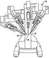
도 1은 여러 가지 실시예에 따르는, 수술하는데 사용되는 최소 침습 로봇 수술 시스템의 평면도이다.
도 2는 여러 가지 실시예에 따르는 로봇 수술 시스템용 의사의 제어 콘솔의 사시도이다.
도 3은 여러 가지 실시예에 따르는 로봇 수술 시스템 전자장치 카트의 사시도이다.
도 4에는 여러 가지 실시예에 따르는 로봇 수술 시스템이 도식적으로 나타나 있다.
도 5a는 여러 가지 실시예에 따르는 로봇 수술 시스템의 환자 측 카트(수술 로봇)의 정면도이다.
도 5b는 여러 가지 실시예에 따르는 로봇 수술 도구의 정면도이다.
도 6은 여러 가지 실시예에 따르는, 반대편에 있는 클램핑 죠(clamping jaw)를 가지고 있는 엔드 이펙터를 포함하는 로봇 수술 도구의 사시도이다.
도 7은 여러 가지 실시예에 따르는, 6열의 스테이플을 가지고 있는 직선형 스테이플링 및 커팅 수술 도구의 탈착가능한 카트리지의 사시도이다.
도 8은 여러 가지 실시예에 따르는, 도 7에서의 카트리지 및 부착된 스테이플 리테이너의 사시도이다.
도 9는 여러 가지 실시예에 따르는, 도 7에서의 카트리지와 엔드 이펙터 조립체 사이의 부착상태 세부사항이 나타나 있는 단면도이다.
도 10은 도 7에서의 카트리지의 구성요소를 도시하는 분해도이다.
도 11a와 11b는 도 7에서의 카트리지의 인쇄 회로 조립체를 도시하는 사시도이다.
도 12는 여러 가지 실시예에 따르는, 직선형 스테이플링 및 커팅 수술 도구의 탈착가능한 카트리지의 단면도이다.
도 13a는 여러 가지 실시예에 따르는, 4열의 스테이플을 가지고 있는 직선형 스테이플링 및 커팅 수술 도구의 탈착가능한 카트리지의 스테이플 전개 관련 구성요소의 부분 사시도이다.
도 13b는 도 13a의 카트리지의 구동 부재의 사시도이다.
도 13c는 도 13a의 카트리지의 스테이플 푸셔의 사시도를 포함한다.
도 14a에는 도 7에서의 카트리지의 하우징의 원위 단부가 나타나 있다.
도 14b에는 도 7에서의 카트리지의 스테이플 푸셔의 사시도를 포함한다.
도 14c는 도 7에서의 카트리지의 구동 부재의 사시도이다.
도 14d는 도 7에서의 카트리지의 구동 부재의 평면도이다.
도 14e는 도 7에서의 카트리지의 구동 부재의 측면도이다.
도 14f에는 도 7에서의 카트리지의 구동 부재의 원위 단부가 나타나 있다.
도 14g에는 도 14d에 형성되어 있는 바와 같이, 도 7에서의 카트리지의 구동 부재를, A-A를 따라 자른 단면도가 나타나 있다.
도 14h에는 도 14d에 형성되어 있는 바와 같이, 도 7에서의 카트리지의 구동 부재를, B-B를 따라 자른 단면도가 나타나 있다.
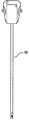
도 15a는 도 7에서의 카트리지의 나이프 부재의 사시도이다.
도 15b는 도 7에서의 카트리지의 나이프 부재의 측면도이다.
도 15c는 도 7에서의 카트리지의 나이프 부재의 평면도이다.
도 15d 내지 도 15g에는 여러 가지 실시예에 따르는, 나이프 부재의 부분 측면도들이 각각 나타나 있다.
도 15h에는 여러 가지 실시예에 따르는, 나이프 부재의 평면도가 나타나 있다.
도 16a에는 도 7에서의 카트리지의 나이프 부재의 작동이 도시되어 있다.
도 16b에는 여러 가지 실시예에 따르는, 구동 부재의 원위방향으로의 이동 동안 나이프 부재가 원위방향으로 이동하는 것을 저지하기 위해서 나이프 부재의 돌출부를 받아들이는 하우징의 리셉터클이 나타나 있다.
도 16c에는 여러 가지 실시예에 따르는, 구동 부재가 나이프 부재를 원위방향으로 구동시키는 동안 구동 부재와 연결되는 나이프 부재가 나타나 있다.
도 16d에는 여러 가지 실시예에 따르되, 나이프의 원위 단부를 상승시키고 나이프의 커팅 블레이드를 하우징 속으로 하강시키기 위해서, 나이프 부재의 원위 단부가 하우징의 캠 표면을 따라 구동된 후에, 작동 스트로크의 종료시에 있는 나이프 부재가 나타나 있다.
도 17에는 여러 가지 실시예에 따르는, 직선형 스테이플링 및 커팅 수술 도구로부터 스테이플을 전개하고 직선형 스테이플링 및 커팅 수술 도구 내에서 커팅 블레이드를 관절운동시키는 방법의 단계가 나열되어 있다.
도 18에는 도 17에서의 방법의 선택적인 단계가 나열되어 있다.1 is a plan view of a minimally invasive robotic surgical system used for surgery, in accordance with various embodiments.
2 is a perspective view of a physician's control console for a robotic surgical system in accordance with various embodiments.
3 is a perspective view of a robotic surgical system electronics cart in accordance with various embodiments.
4 schematically shows a robotic surgical system in accordance with various embodiments.
5A is a front view of a patient side cart (surgical robot) of a robotic surgical system in accordance with various embodiments.
5B is a front view of a robotic surgical tool in accordance with various embodiments.
FIG. 6 is a perspective view of a robotic surgical tool including an end effector having an opposite clamping jaw, in accordance with various embodiments. FIG.
7 is a perspective view of a removable cartridge of a straight stapling and cutting surgical tool having six rows of staples, in accordance with various embodiments.
8 is a perspective view of the cartridge and attached staple retainer in FIG. 7, in accordance with various embodiments.
9 is a cross-sectional view illustrating attachment details between the cartridge and end effector assembly in FIG. 7, in accordance with various embodiments.
FIG. 10 is an exploded view showing the components of the cartridge in FIG. 7.
11A and 11B are perspective views illustrating the printed circuit assembly of the cartridge in FIG. 7.
12 is a cross-sectional view of a removable cartridge of a straight stapling and cutting surgical tool, in accordance with various embodiments.
13A is a partial perspective view of a staple deployment related component of a removable staple of a straight stapling and cutting surgical tool having four rows of staples, according to various embodiments.
FIG. 13B is a perspective view of the drive member of the cartridge of FIG. 13A.
FIG. 13C includes a perspective view of a staple pusher of the cartridge of FIG. 13A.
FIG. 14A shows the distal end of the housing of the cartridge in FIG. 7.
FIG. 14B includes a perspective view of the staple pusher of the cartridge in FIG. 7.
FIG. 14C is a perspective view of the drive member of the cartridge in FIG. 7. FIG.
14D is a plan view of the drive member of the cartridge in FIG.
14E is a side view of the drive member of the cartridge in FIG.
FIG. 14F shows the distal end of the drive member of the cartridge in FIG. 7.
FIG. 14G is a cross-sectional view taken along AA of the drive member of the cartridge in FIG. 7, as formed in FIG. 14D.
FIG. 14H is a cross-sectional view taken along the BB of the drive member of the cartridge in FIG. 7 as formed in FIG. 14D.
FIG. 15A is a perspective view of the knife member of the cartridge in FIG. 7. FIG.
15B is a side view of the knife member of the cartridge in FIG.
15C is a plan view of the knife member of the cartridge in FIG.
15D-15G show partial side views of the knife member, respectively, in accordance with various embodiments.
15H shows a plan view of a knife member, in accordance with various embodiments.
FIG. 16A shows the operation of the knife member of the cartridge in FIG. 7.
16B shows a receptacle of the housing that receives the protrusion of the knife member to prevent the knife member from moving distally during the distal movement of the drive member, according to various embodiments.
16C shows a knife member connected with the drive member while the drive member drives the knife member distal in accordance with various embodiments.
16D, according to various embodiments, after the distal end of the knife member is driven along the cam surface of the housing to raise the distal end of the knife and lower the cutting blade of the knife into the housing, at the end of the operating stroke. The knife member is shown.
FIG. 17 lists the steps of a method of deploying staples from a straight stapling and cutting surgical tool and articulating the cutting blade within the straight stapling and cutting surgical tool, according to various embodiments.
FIG. 18 lists the optional steps of the method in FIG. 17.
다음에 오는 발명의 상세한 설명에서, 본 발명의 여러 가지 실시예가 설명될 것이다. 설명하기 위하여, 특정 구성과 세부사항은 실시예의 완전한 이해를 제공하기 위하여 설명되어 있다. 그러나, 본 발명이 특정 세부사항 없이도 실시될 수 있다는 것은 당해 기술분야의 통상의 기술자에게 자명할 것이다. 또한, 공지의 특징부는 설명되고 있는 실시예를 불명료하게 하지 않기 위하여 생략되거나 단순화될 수 있다.In the following detailed description of the invention, various embodiments of the invention will be described. For purposes of explanation, specific configurations and details are set forth in order to provide a thorough understanding of the embodiments. However, it will be apparent to one skilled in the art that the present invention may be practiced without the specific details. In addition, known features may be omitted or simplified in order not to obscure the embodiments being described.
최소 침습 로봇 수술Minimally invasive robotic surgery
도면에 대해 참조하면, 여기에서 유사한 참조 번호는 몇몇 도면 전체에 걸쳐서 유사한 부품을 나타낸다. 도 1은 최소 침습 로봇 수술(Minimally Invasive Robotic Surgical; MIRS) 시스템(10)의 평면도이고, 이 최소 침습 로봇 수술 시스템은 수술대(14) 위에 드러누워 있는 환자(12)에게 행해지고 있는 최소 침습 진단 과정이나 수술 과정을 실행하는데 사용되는 것이 통상적이다. 이 시스템은 이 과정 동안 의사(18)에 의해 사용되는 의사의 콘솔(16)을 포함한다. 1인 이상의 어시스턴트(20) 역시 이 과정에 참여할 수 있다. MIRS 시스템(10)은 또한 환자 측 카트(22)(수술 로봇)와 전자장치 카트(24)를 포함한다. 환자 측 카트(22)는, 의사(18)가 콘솔(16)을 통하여 수술 부위를 관찰하는 동안, 적어도 하나의 제거가능하게 연결되는 도구 조립체(26)(이하에서는 간단히 "도구(tool)"로 지칭됨)를 환자(12)의 신체 내의 최소 침습 절개부를 통과하여 조종할 수 있다. 수술 부위의 영상은 내시경(28)을 배향하는 환자 측 카트(22)에 의해 조종될 수 있는 입체 내시경과 같은 내시경(28)에 의하여 획득될 수 있다. 전자장치 카트(24)는 의사의 콘솔(16)을 통하여 추후에 의사(18)에게 보여주기 위하여 수술 부위의 영상을 처리하는데 사용될 수 있다. 동시에 사용되는 수술 도구(26)의 개수는 일반적으로 다른 요인들 중에서 진단 과정이나 수술 과정 및 수술실 내부의 공간 제약에 좌우될 것이다. 이 과정 동안 사용되는 도구(26)들 중 하나 이상을 변경하는 것이 필요한 경우에는, 어시스턴트(20)는 환자 측 카트(22)로부터 도구(26)를 제거할 수 있고 이 도구를 수술실 내의 다른 도구(26)와 교체할 수 있다.Referring to the drawings, like reference numerals refer to like parts throughout the several views. 1 is a plan view of a Minimally Invasive Robotic Surgical (MIRS)
도 2는 의사의 콘솔(16)의 사시도이다. 의사의 콘솔(16)은, 의사(18)가 수술 부위를 좌표계로 표현하여 입체적으로 관찰할 수 있는, 좌안 표시장치(32)와 우안 표시장치(34)를 포함하고, 이로써 깊이를 인지할 수 있다. 의사의 콘솔(16)은 하나 이상의 입력 제어 장치(36)를 더 포함하고, 이 장치는 결과적으로 환자 측 카트(22)(도 1에 도시됨)가 하나 이상의 도구를 조종하게 한다. 입력 제어 장치(36)는, 의사에게 원격현장감(telepresence), 또는 의사가 도구(26)를 직접 제어하고 있다는 강한 느낌을 가지도록 입력 제어 장치(36)가 도구(26)와 일체를 이루고 있다는 인지를 제공하기 위해서, 관련 도구(26)(도 1에 도시됨)와 같이 동일한 자유도를 제공할 수 있다. 이를 위하여, 위치 센서, 힘 센서 및 촉각 피드백 센서(미도시)는 입력 제어 장치(36)를 통하여 도구(26)로부터 다시 의사의 손 쪽으로 위치, 힘 및 촉감을 전달하는데 이용될 수 있다.2 is a perspective view of the doctor's
의사의 콘솔(16)은 보통 환자와 마찬가지로 동일한 방에 위치되어서, 의사는 그 과정을 직접 모니터할 수 있고, 필요한 경우에는 직접 참여할 수도 있고, 어시스턴트에게 전화나 다른 통신 매체를 통하여 말하지 않고 직접 말할 수도 있다. 그러나, 의사는 원격 수술 과정을 가능하게 하는 환자로부터의 원격의 다른 장소 또는 다른 방, 완전히 다른 건물에 위치될 수 있다.The doctor's
도 3은 전자장치 카트(24)의 사시도이다. 전자장치 카트(24)는 내시경(28)과 연결될 수 있고, 캡처된 영상을 처리하는 프로세서를 포함할 수 있는데, 이 캡처된 영상은 원격으로 그리고/또는 국소적으로 위치되어 있는 다른 적합한 표시장치 또는 의사의 콘솔에 위치해 있는 의사에게 추후에 보여주기 위한 것이다. 예를 들어, 입체 내시경이 사용되는 경우, 전자장치 카트(24)는 수술 부위에 관하여 좌표계로 표현된 입체 영상을 의사에게 제공하는 캡처된 영상을 처리할 수 있다. 이러한 좌표결정은 마주하는 영상 사이에서의 정렬을 포함하고, 입체 내시경의 입체적 작동 거리를 조정하는 것을 포함한다. 다른 예에서, 영상 처리는 광학적 수차와 같은 영상 캡처 장치의 촬상 에러를 보상하기 위해서 미리 결정된 카메라 보정 파라미터의 사용을 포함할 수 있다.3 is a perspective view of an
도 4에는 로봇 수술 시스템(50)(도 1에서의 MIRS 시스템(10)과 유사함)이 도식적으로 나타나 있다. 위에서 언급한 바와 같이, 의사의 콘솔(52)(도 1에서의 의사의 콘솔(16)과 유사함)은 최소 침습 시술 동안 환자 측 카트(수술 로봇)(54)(도 1에서의 환자 측 카트(22)와 유사함)를 제어하는 의사에 의해 사용될 수 있다. 환자 측 카트(54)는, 시술 부위의 영상을 캡처하고 이 캡처된 영상을 전자장치 카트(56)(도 1에서의 전자장치 카트(24)와 유사함)에 출력하는 입체 내시경과 같은 촬상 장치를 사용할 수 있다. 위에서 언급한 바와 같이, 전자장치 카트(56)는 추후에 보여주기 전에 여러 가지 방법으로 캡처된 영상을 처리할 수 있다. 예를 들어, 전자장치 카트(56)는 의사의 콘솔(52)을 통하여, 결합된(combined) 영상을 의사에게 보여주기 전에 캡처된 영상을 가상 제어 인터페이스와 중첩(overlay)시킬 수 있다. 환자 측 카트(54)는 외부의 전자장치 카트(56)를 처리하기 위해 캡처된 영상을 출력할 수 있다. 예를 들어, 환자 측 카트(54)는 캡처된 영상을 처리하는데 사용될 수 있는 프로세서(58)에 캡처된 영상을 출력할 수 있다. 영상은 전자장치 카트(56)와 프로세서(58)의 결합에 의하여 처리될 수 있는데, 이들의 결합은 캡처된 영상을 공동으로 순차적으로 처리하기 위해서 그리고/또는 그 결합방식으로 처리하기 위해서 함께 연결될 수 있다. 하나 이상의 별개의 표시장치(60)는, 시술 부위의 영상이나 다른 관련 영상과 같은 영상을 국부적으로 표시하기 위해 그리고/또는 원격으로 표시하기 위해 프로세서(58) 및/또는 전자장치 카트(56)와 연결될 수도 있다.4 schematically shows a robotic surgical system 50 (similar to the
도 5a와 도 5b에는 각각 환자 측 카트(22)와 수술 도구(62)가 나타나 있다. 수술 도구(62)는 수술 도구(26)의 일 실시예이다. 여기에 나타나 있는 환자 측 카트(22)는, 시술 부위의 영상을 캡처하기 위하여 사용되는 입체 내시경과 같은 촬상 장치(28)와 3개의 수술 도구(26)의 조종을 제공한다. 조종은 수개의 로봇 조인트를 가지는 로봇 메커니즘에 의해 제공된다. 촬상 장치(28)와 수술 도구(26)는 환자 내부의 절개부를 통과하여 위치결정되고 조종될 수 있고, 그 결과 운동학적 원격 중심(kinematic remote center)은 절개부에 유지되어 절개부의 크기를 최소화한다. 수술 부위의 영상은 수술 도구가 촬상 장치(28)의 가시 범위 내에 위치결정될 때 수술 도구(26)의 원위 단부의 영상을 포함할 수 있다.5A and 5B show
조직 파지용For tissue holding엔드End이펙터Effector
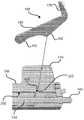
도 6에는 수술 도구(70)가 나타나 있는데, 이 수술 도구는 근위 섀시(72), 기구 샤프트(74), 및 환자 조직을 파지하도록 관절운동될 수 있는 죠(78)를 가지고 있는 원위 엔드 이펙터(76)를 포함한다. 근위 섀시는 입력 연결장치(coupler)를 포함하는데, 이 입력 연결장치는, 환자 측 카트(22)의 상응하는 출력 연결장치와 접속되고 이 출력 연결장치에 의하여 구동되도록 구성되어 있다. 입력 연결장치는 기구 샤프트(74) 내부에 배치되어 있는 구동 샤프트와 구동가능하게 연결되어 있다. 구동 샤프트는 엔드 이펙터(76)와 구동가능하게 연결되어 있다.6 shows a surgical tool 70, which is a distal end effector having a proximal chassis 72, an instrument shaft 74, and a jaw 78 that can be articulated to grip patient tissue. 76). The proximal chassis includes an input coupler, which is configured to be connected to and driven by the corresponding output connector of the
직선형Straight스테이플링Stapling 및 And커팅Cutting 수술 기구 Surgical instruments
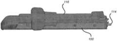
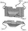
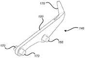
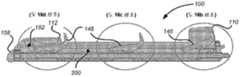
도 7에는 여러 가지 실시예에 따르는, 직선형 스테이플링 및 커팅 수술 기구의 탈착가능한 카트리지(100)가 나타나 있다. 카트리지(100)는 엔드 이펙터의 죠에 제거가능하게 부착되도록 구성되어 있다. 카트리지는, 엔드 이펙터의 죠에 부착되어 있는 근위 단부(102)와, 엔드 이펙터의 죠의 상응하는 원위 단부에 배치되어 있는 원위 단부(104)를 가지고 있다. 카트리지(100)는 6열의 스테이플 개구부(106), 길이방향 슬롯(108), 근위 나이프 보관소(110), 원위 나이프 보관소(112) 및 회전 입력부(114)를 포함한다. 여러 가지 실시예에서, 스테이플은 스테이플로부터의 전개를 위해 각각의 스테이플 개구부에 배치되어 있다. 길이방향 슬롯(108)은, 나이프 부재가 근위 나이프 보관소(110)로부터 원위 나이프 보관소(112)로 이동되고 있을 때, 길이방향 슬롯으로부터 뻗어 있는 나이프 부재(미도시)의 커팅 블레이드를 수용한다. 작동시, 스테이플은 전개되어 카트리지 근위 단부(102)에서 시작하여 카트리지 원위 단부(104)로 전진한다. 커팅 블레이드는 완전히 스테이플링된 조직만이 절단되는 것을 보장하기 위해서 조직의 스테이플링을 뒤따르도록 이동된다. 도 8에는 카트리지(100)를 사용하기 전에 제거되는, 스테이플 리테이너(116)가 부착된 상태의 카트리지(100)가 나타나 있다.7 shows a
도 9는 여러 가지 실시예에 따르는, 엔드 이펙터(118)에 부착되어 있는 카트리지(100)가 상세하게 나타나 있는 단면도이다. 엔드 이펙터(118)는 하부 죠(120), 상부 죠(122), 2 자유도 리스트(wrist)(124), 회전 구동식 클램핑 메커니즘(126) 및 스프링 장전식 커플링(128)을 포함한다. 하부 죠(120)는 카트리지(100)를 수용하고 지지할 뿐만 아니라, 스프링 장전식 커플링(128)에 대하여 카트리지(100)를 위치결정하도록 구성되어 있다. 상부 죠(122)는 하부 죠(120)와 피벗가능하게 연결되어, 조직을 고정시키기 위해서 하부 죠(120)에 대하여 관절운동한다. 상부 죠(122)는, 스테이플의 전개시 스테이플을 "B"자형으로 형성하도록 구성되어 있고, 스테이플 개구부(106)에 대하여 위치결정되어 있는 스테이플 형성 리세스부(staple forming recess)를 포함한다.9 is a detailed cross-sectional view of a
2 자유도 리스트(124)는, 기구 샤프트(130)에 대하여 직교하는 2개의 축 둘레에서 엔드 이펙터(118)를 관절운동시키기 위해, 엔드 이펙터(118)를 기다란 기구 샤프트(130)에 부착한다. 사용될 수 있는 적합한 2 자유도 리스트의 세부사항은 2010년 11월 12일에 출원된 "2 자유도 리스트를 가진 수술 도구(SURGICAL TOOL WITH A TWO DEGREE OF FREEDOM WRIST)"라는 명칭의 미국 출원 제12/945,748호(Attorney Docket No. ISRG02350/US)에 개시되어 있고, 그 전체 명세서는 본 명세서에 참조사항으로 통합되어 있다.The two degrees of
회전 구동식 클램핑 메커니즘(126)은 상부 죠(122)를 하부 죠(120)에 대하여 작동시켜서 조직을 상부 죠와 하부 죠 사이에 확고히 고정시킨다. 클램핑 메커니즘(126)은 기구 샤프트(130)의 내부에 배치되어 있는 제 1 구동 샤프트(132)에 의하여 회전 구동된다. 사용될 수 있는 적합한 회전 구동식 클램핑 메커니즘의 세부사항은 2010년 11월 12일에 출원된 "이중 폐쇄 메커니즘을 가진 엔드 이펙터(END EFFECTOR WITH REDUNDANT CLOSING MECHANISM)"라는 명칭의 미국 출원 제12/945,541호(Attorney Docket No. ISRG02330/US)에 개시되어 있고, 그 전체 명세서는 본 명세서에 참조사항으로 통합되어 있다.The rotationally driven
스프링 장전식 커플링(spring-loaded coupling)(128)은 카트리지(100)의 리드 스크루(134)를 연장 샤프트(136)와 회전가능하게 연결하고, 연장 샤프트(136)는 기구 샤프트(130) 내부에 배치되어 있는 제 2 구동 샤프트(138)에 의해 구동된다. 스프링 장전식 커플링(128)은 코일 스프링(140)과 커플링 이음쇠(coupling fitting)(142)를 포함한다. 나타나 있는 실시예에서, 커플링 이음쇠(142)는 3-로브(lobe) 스플라인 리셉터클을 이용하는데, 이 스플라인 리셉터클은 연장 샤프트(136)와 회전 입력부(114)로 된, 3개의 측면이 형성된(three-sided) 외부 표면과 접속한다. 스프링 장전식 커플링(142)은 3-로브 스플라인의 각도 부정렬상태를 조절하는데, 이 각도 부정렬은 카트리지(100)가 엔드 이펙트(118) 속에 설치될 때 일어날 수 있다. 스프링 장전식 커플링(142)은 각도 정렬상태로 회전될 때 3-로브 스플라인과 완전히 맞물린다. 리드 스크루(134)의 회전은 카트리지(100)의 구동 부재(144)를 병진운동시키는데 사용된다. 구동 모터(144)의 합성 운동(resulting motion)은 전개된 스테이플로 이루어진 일정한 열의 중심 아래에서 고정된 조직을 절단하기 위해서 스테이플을 전개하고 카트리지(100)의 나이프 부재(146)를 원위방향으로 전진이동시키는데 사용된다.A spring-loaded
엔드 이펙터(118)는 제 1 유니버셜 조인트 조립체(148)와 제 2 유니버셜 조인트 조립체(150)를 포함한다. 제 1 유니버셜 조인트(148)는 클램핑 메커니즘(126)을 제 1 구동 샤프트(132)에 회전가능하게 연결한다. 제 2 유니버셜 조인트 조립체(150)는 연장 샤프트(136)를 제 2 구동 샤프트(138)에 회전가능하게 연결한다. 제 1 및 제 2 유니버셜 조인트 조립체(148, 150) 각각은 기구 샤프트(130)에 대한 엔드 이펙터(118)의 피칭운동과 요잉운동의 범위에 적합한 각도의 범위를 통하여 토크를 전달하도록 구성되어 있다. 사용될 수 있는 적합한 유니버셜 조인트 조립체의 세부사항은 2010년 11월 12일에 출원된 "이중 유니버셜 조인트(DOUBLE UNIVERSAL JOINT)"라는 명칭의 미국 출원 제12/945,740호(Attorney Docket No. ISRG02340/US)에 개시되어 있고, 그 전체 명세서는 본 명세서에 참조사항으로 통합되어 있다.The
제 1 구동 샤프트(132)와 제 2 구동 샤프트(138)는 독자적으로 회전될 수 있는 기구 샤프트(130)의 센터라인에 대해 오프셋상태로 배치되어 있다. 제 1 구동 샤프트(132)와 제 2 구동 샤프트(138)를 작동시키는데 사용될 수 있는 적합한 구동 메커니즘의 세부사항은 2010년 11월 12일에 출원된 "독자적으로 회전하는 부재 내의 병렬 구동 샤프트용 모터 인터페이스(MOTOR INTERFACE FOR PARALLEL DRIVE SHAFTS WITHIN AN INDEPENDENTLY ROTATING MEMBERS)"라는 명칭의 미국 출원 제12/945,461호(Attorney Docket No. ISR02360/US)에 개시되어 있고, 그 전체 명세서는 본 명세서에 참조사항으로 통합되어 있다.The
도 10은 카트리지(100)의 구성요소를 도시하고 있는 분해도이다. 도시된 구성요소는 리테이너(116, 66), 인쇄 회로 조립체(printed circuit assembly; PCA) 스프링(154), PCA(156), 카트리지 몸체(158), 스테이플 푸셔(160), 나이프 부재(146), 리드 스크루(134), 구동 부재(144), 스러스트 와셔(162), 리드 스크루 너트(164) 및 커버(166)를 포함한다. 카트리지 몸체(158)는 6열로 정렬되어 있는 스테이플 개구부(106)와 리테이너(66)를 가지고, 3열의 스테이플 개구부(106)는 길이방향 슬롯(108)의 각 측면 상에 배치되어 있다. 리테이너(116)는 카트리지(100)에 제거가능하게 부착가능하고, 카트리지(100)를 사용하기 전에 스테이플(152)을 유지하기 위해서 스테이플 개구부(106)를 덮는다. 스테이플 푸셔(160)는 스테이플(152)과 접속하고 카트리지 몸체(158)와 미끄러지듯 접속한다. 구동 부재(144)가 원위 단부(104)를 향하여 이동할 때, 리드 스크루(176)를 따르는 구동 부재(144)의 운동은 구동 부재(144)의 원위방향으로 향하고 있는 경사 표면(176)에 의하여 스테이플 푸셔(160)의 맞물림을 야기하여, 스테이플 푸셔(160)를 카트리지 몸체(158)에 대하여 위쪽으로 구동해서 스테이플(152)을 전개한다. 나이프 부재(146)는 근위 돌출부(168)와 원위 돌출부(170)를 포함한다. 커버(166)는 카트리지 몸체(158)에 부착된다.10 is an exploded view showing the components of the
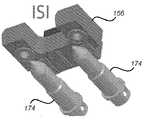
도 11a와 도 11b에는 PCA(156)와 PCA 스프링(154)이 추가로 도시되어 있다. PCA 스프링(154)은 카트리지 몸체(158)와 접속하고 PCA(156)를 유지한다. PCA 스프링(154)은, 카트리지 몸체(158) 위를 걸어 잠궈서 PCA 스프링(154)을 유지하는 PCA 스프링 후크(172)를 포함한다. 카트리지(100)가 엔드 이펙터(118)에 부착될 때, 엔드 이펙터(118)의 기구 핀(174)은 PCA(156) 밑을 미끄럼이동하고 PCA(156)를 들어올리고, 이로써 PCA(156)를 기구 핀(174)과 전기적으로 연결하고 증가된 관련 공차의 사용을 허용한다. 그러나 이 배열은 기구 핀(174)이 PCA(156)와 적합한 접촉을 형성하는 한 문제되지 않는다. 따라서, 일부 실시예에서, PCA(156)는 에지 상에서 회전될 수 있고, 그 결과 나타나 있는 칩은 하중 경로(load path)를 벗어난다. PCA(156)는 카트리지(100)와 관련된 정보를 이용하는데 사용될 수 있고 그리고/또는 식별, 구성을 전자적으로 저장하는데 사용될 수 있다.11A and 11B further illustrate
카트리지(100)는 다음의 조립체 순서를 이용하여 조립될 수 있다. 첫번째로, 카트리지 몸체(158)가 "바텀 업(bottom up)" 배향에 있는 상태에서, 스테이플 푸셔(160)는 스테이플 개구부(106) 속에 설치된다. 다음으로, 나이프 부재(146)는, 나이프 부재(146)의 근위 돌출부(168)가 카트리지 몸체(158) 내의 근위 리셉터클 속에 배치되어 있는 상태에서, 근위 나이프 보관소(110) 속에 설치된다. 다음으로, 구동 부재(144), 스러스트 와셔(162) 및 리드 스크루 너트(164)는 리드 스크루(134) 위에 설치되고, 리드 스크루 너트(164)는 리드 스크루(134)의 단부와 높이가 같아지도록 레이저 용접된다. 합성 리드 스크루 조립체는, 구동 부재(144)가 리드 스크루(134)의 근위 단부에 위치결정되어 있는 상태에서, 카트리지 몸체(158) 속에 설치된다. 다음으로, 커버(166)는 카트리지 몸체(158) 위에 설치된다. 합성 조립체는, 예컨대 합성 조립체를 윤활유 속에 침지함으로써 윤활될 수 있다. 다음으로, 조립체는 "탑 업(top up)" 배향으로 뒤집히고, PCA(156)는 설치된다. 다음으로, PCA 스프링(154)은 PCA 스프링 후크(172)가 걸어 잠길 때까지 카트리지 몸체(158) 위에서 밀린다. 다음으로, 스테이플(152)은 스테이플 개구부(106) 속에 설치되고, 그 후 리테이너(116)가 설치된다. 마지막으로, 데이터는 PCA(156) 속에 설치된다.The
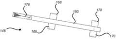
도 12에는 시작 위치(도시됨)부터 종료 위치(미도시됨)까지의 나이프 부재(146)의 작동과 관련 있는 카트리지(100)의 구성요소가 도시되어 있는데, 시작 위치에서는 나이프 부재(146)가 근위 나이프 보관소(110)에 의해 보호되고 종료 위치에서는 나이프 부재(146)가 원위 나이프 보관소(112)에 의해 보호된다. 리드 스크루(134)는 카트리지 몸체(158)에 대한 회전을 위해 장착되고, 카트리지 몸체(158)의 길이를 따라 뻗어 있다. 구동 부재(144)는, 리드 스크루(134)의 회전에 응답하여 리드 스크루(134)를 따르는 병진운동을 위하여, 내부에 나사산이 형성되어 있고 리드 스크루(134)와 연결되고 카트리지 몸체(158) 내에 미끄럼이동가능하게 장착된다. 구동 부재(144)는 하나 이상의 원위방향으로 향하고 있는 경사(176)를 포함하는데, 이 경사는 구동 부재(144)가 카트리지 몸체(100)의 원위 단부(104)를 향하여 전진이동될 때 스테이플 푸셔(160)에 맞물리도록 구성되어 있다. 나이프 부재(146)는 커팅 블레이드(178), 몸체부(180), 몸체부(180)의 양쪽으로부터 뻗어 있는 근위 돌출부(168), 또한 몸체부(180)의 양쪽으로부터 뻗어 있는 근위 돌출부(170)를 포함한다. 아래에서 더 상세하게 설명되는 바와 같이, 구동 부재(144)가 그 도시되어 있는 시작 위치로부터 원위방향으로 전진이동될 때, 나이프 부재(146)는 구동 부재(144)가 원위 돌출부(170)에 접촉할 때까지 카트리지 몸체(158)에 대하여 정지상태로 존속하고, 그 후 나이프 부재(146)는 구동 부재(144)에 의하여 구동된다. 구동 부재(144)의 원위방향 이동거리의 종료지점 근처에서, 나이프 부재(146)의 원위 단부는 카트리지 몸체(158)의 캠 표면(182)을 따라 구동되고, 이로써 나이프 부재(146)의 원위 단부를 상승시켜 커팅 블레이드(178)를 카트리지 몸체(158)의 상부 표면(184) 아래와 원위 나이프 보관소(112) 속으로 하강시킨다. 나이프 부재 몸체부(180)는 길이방향 슬롯(108)을 형성하는, 카트리지 몸체(158)의 마주하는 표면에 의하여 구속된다. 나이프 근위 돌출부(168)와 원위 돌출부(170)는 길이방향 슬롯(108)의 폭을 넘어서 나이프 부재 몸체부(180)의 양쪽에서 뻗어 있고, 이로써 나이프 부재(146)를 카트리지 몸체(158)와 구동 부재(144)에 대하여 수직방향으로 구속하는데 이용된다.FIG. 12 shows the components of the
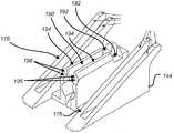
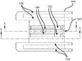
도 13a 내지 도 13c에는 여러 가지 실시예에 따르는, 4열의 스테이플을 가지는 직선형 스테이플링 및 커팅 수술 도구의 스테이플 전개 관련 구성요소가 나타나 있다. 카트리지(100)와 유사하게도, 내부에 나사산이 형성된 구동 부재(144-4)는, 리드 스크루(134)의 회전에 응답하여 리드 스크루(134)를 따르는 병진운동을 위해, 리드 스크루(134)와 연결되고, 카트리지 몸체 내에 미끄럼이동가능하게 장착된다(미도시). 구동 부재(144-4)는 원위방향으로 향하고 있는 2개의 직선형 경사(176-4)를 포함하는데, 이 경사는 구동 부재(144-4)가 리드 스크루(134)를 따라 원위방향으로 전진이동될 때 스테이플 푸셔(160-4)에 맞물린다. 각각의 스테이플 푸셔(160-4)는 단일의 스테이플을 밀도록 구성되어 있다(미도시). 각각의 스테이플 푸셔(160-4)는 2개의 직선형 경사 표면(186-6)을 가지고, 이 표면은 구동 부재(144-4)의 상응하게 경사진 2개의 직선형 경사(176-4)와 접속하도록 구성되어 있다. 각각의 스테이플 푸셔(160-4)는 카트리지 몸체 내부의 스테이플 개구부와 미끄러지듯 접속하도록 형성되어 있는 단부(188-4)를 가진다.13A-13C illustrate staple deployment related components of a straight stapling and cutting surgical tool with four rows of staples, according to various embodiments. Similar to the
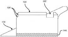
구동 부재(144-4)는 나이프 부재(146)를 수용하고 나이프 부재(146)와 접속하도록 구성되어 있어서, 처음에는 나이프 부재(146)에 대하여 원위방향으로 이동하고, 이후 나이프 부재(146)를 카트리지 몸체의 원위 단부를 향하여 구동시키고, 나이프 부재(146)의 원위 단부를 카트리지 몸체(158)의 원위방향 경사(182) 위로 민다. 나이프 부재(146)와 접속하는 구동 부재(144-4) 특징부는 중앙 슬롯(190), 근위 리셉터클(192), 정상 표면(194) 및 원위 표면(196)을 포함한다. 중앙 슬롯(190)은, 근위 나이프 보관소(110) 내의 시작 위치로부터 원위 나이프 보관소(112) 내의 종료 위치까지의 나이프 부재(146)의 스트로크 내내 나이프 몸체부(180)를 수용한다. 근위 리셉터클(192)은 나이프 부재(146)가 구동 부재(144-4)에 의하여 원위방향으로 구동되는 동안 나이프 부재 근위 돌출부(168)를 수용한다. 정상 표면(194)은 근위 돌출부(168)와 접속하여, 구동 부재(144-4)의 최초의 원위방향 이동 동안 카트리지 몸체(158) 내의 리셉터클과 근위 돌출부(168) 사이의 맞물림을 확고히 하고, 이때 구동 부재(144-4)는 카트리지 몸체(158)와 나이프 부재(146) 모두에 대하여 원위방향으로 이동되고, 나이프 부재(146)는 근위 돌출부(168)와 관련 카트리지 몸체 리셉터클 사이의 맞물림에 의하여 카트리지 몸체(158)에 대하여 정지상태가 유지되고 있다. 나이프 부재(146)에 대한 구동 부재(144-4)의 최초의 상대적인 원위방향 이동 후에, 구동 부재 원위 표면(196)은 나이프 부재 원위 돌출부(170)와 접속하여, 구동 부재(146)를 원위방향으로 구동시키고, 나이프 부재(146)가 원위방향으로 구동되고 있을 때, 길이방향 슬롯(108)의 양쪽 측면 상의 카트리지 몸체(158)의 표면과 결합하여 원위 돌출부(170)의 수직방향 위치를 제어한다. 나이프 부재(146)의 원위 부분이 캠 표면(182) 위쪽으로 구동될 때, 원위 돌출부(170)는 원위 표면(196)으로부터 떨어져 있고, 나이프 부재(146)는, 나이프 부재 근위 돌출부(168)와 접속하여 나이프 부재(146)를 캠 표면(182)을 따라 구동시키는, 구동 부재 근위 리셉터클(192)의 근위 벽에 의해 구동되고, 이로써 커팅 블레이드(178)를 원위 나이프 보관소(112) 속에 집어넣는다.The drive member 144-4 is configured to receive the
도 14a에는 카트리지 몸체(158)의 원위 단부가 나타나 있다. 도 14b에는 스테이플 푸셔(160) 중 하나의 평면도와 사시도가 나타나 있다. 도시된 바와 같이, 스테이플 개구부(106)와 스테이플 푸셔(160)는 상보적인 형상을 가지고, 그 결과 각각의 스테이플 푸셔(160)는, 구동 부재(144)가 카트리지 원위 단부(104)를 향하여 병진운동될 때 구동 부재(144)에 의하여 구동되는 것에 응답하는 스테이플 개구부(106) 내부에서의 병진운동을 위하여, 스테이플 개구부(106) 중 하나 내부에 수용된다.14A shows the distal end of the
도 14c 내지 도 14h에는 구동 부재(144)의 추가적인 도시가 제공되어 있다. 도 14c에는 구동 부재(144)의 사시도가 나타나 있다. 도 14d에는 구동 부재(144)의 평면도가 나타나 있다. 도 14e에는 구동 부재(144)의 측면도가 나타나 있다. 도 14f에는 구동 부재(144)의 원위 단부가 나타나 있다. 도 14g에는 도 14d에 정의되어 있는 바와 같이 AA를 자른 단면도가 나타나 있다. 도 14h에는 도 14d에 정의되어 있는 바와 같이 BB를 자른 단면도가 나타나 있다.14C-14H are provided further illustrations of
도 15a 내지 도 15c에는 나이프 부재(146)의 추가적인 도시가 제공되어 있다. 여러 가지 실시예에서, 커팅 블레이드(178)는 나이프 부재 몸체부(180)에 일체를 이루어 형성되어 있다. 근위 돌출부(168)와 원위 돌출부(170)는 나이프 부재 몸체부(180)와 일체를 이룰 수 있고, 또는 나이프 부재 몸체부(180) 내의 횡단방향 홀 속에 핀을 압입함으로써 형성될 수 있다. 몸체부(180)와 핀은, 17-4 PH 스테인리스강, 440A 스테인리스강 또는 420 스테인리스강과 같은 적합한 재료로 형성될 수 있다. 커팅 블레이드(178)는 양쪽 측면 상의 그라운드 에지에 대해 경사형성되어 있지만, 그라운드 에지와 편평할 수도 있고, 또는 어느 한쪽 측면이 그라운드 상에 있으면서 다른 한쪽 측면만이 경사형성되어 있을 수도 있다. 추가적인 연마는 커팅 블레이드(178)의 각각의 측면 상에 다양한 각도를 생성하기 위해서 실행될 수 있다.15A-15C are provided further illustrations of
나이프 부재(146)의 구성은 커팅 블레이드(178)에 대해 튼튼한 지지를 제공할 수 있는데, 이는 커팅 블레이드(178)가 연조직 이외의 어떤 것을 완전히 절단하는데 사용되는 경우에 특히 이로울 수 있다. 예를 들어, 카트리지(100)가 스테이플을 미리 스테이플링된 조직 전체에 걸쳐 설치하는데 사용되는 것이 일어날 수 있고, 이로써 현존하는 스테이플을 커팅 블레이드(178)의 경로 내에 배치하는 것이 가능하고, 그 결과 현존하는 스테이플은 커팅 블레이드(178)에 의하여 절단될 것이다.The construction of the
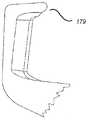
도 15d에는 나이프 부재(146)의 대체 구성이 도시되어 있다. 여러 가지 실시예에서, 나이프 부재는 후크형 팁(179)을 가진 커팅 블레이드(178)를 가지고 있다. 후크형 팁은 뭉툭해지고 원위방향으로 지나서 그리고 측면방향 위쪽, 즉 커팅 블레이드의 최정상 커팅 에지 쪽으로 돌출되어 있다. 후크형 팁(179)은 조직이 커팅 블레이드(178)의 높이 이상으로 기어오르는 것을 방지함으로써 조직의 전체 두께가 절단되는 것을 보장하는데 도움이 될 수 있다. 후크형 팁은, 장치가 고장나서 커팅 블레이드(178)가 노출된 상태로 방치된 경우에 수술실 스태프에 대한 부상의 위험을 감소시킬 수도 있다.15D, an alternative configuration of
도 15e에는 나이프 부재(146)의 다른 대체 구성이 도시되어 있다. 여러 가지 실시예에서, 나이프 부재는 뭉툭해진 팁(184)을 가진 커팅 블레이드(178)를 가진다. 뭉툭해진 팁은 약간 원위방향으로 지나서 돌출되어 있지만(또는 동일직선상에 있지만), 측면방향 위쪽, 즉 커팅 블레이드(179)의 최정상 커팅 에지 쪽으로도 돌출되어 있다. 도 15d의 커팅 블레이드(178)의 후크형 팁(179)과 마찬가지로, 커팅 블레이드(179)의 뭉툭해진 팁(181)은 조직의 기어오름(climb-over)을 방지하고 우발적인 부상의 위험을 감소시키는데 도움이 될 수 있다.Another alternative configuration of
도 15f에는 나이프 부재(146)의 다른 대체 구성이 도시되어 있다. 여러 가지 실시예에서, 나이프 부재는 뭉툭해진 팁을 가진 곡선형 커팅 블레이드(183)를 가지고 있다. 뭉툭해진 팁은 약간 원위방향으로 지나서 돌출되어 있지만(또는 동일직선상에 있지만), 측면방향 위쪽, 즉 커팅 블레이드(183)의 최정상 커팅 에지 쪽으로도 돌출되어 있다. 곡선형 커팅 블레이드(183)의 뭉툭해진 팁은 조직의 기어오름을 방지하고 우발적인 부상의 위험을 감소시키는데 도움이 될 수 있다. 곡선형 커팅 블레이드(183)는 또한 조직을 그 최중앙 부분 내부로 모아서 집중시킴으로써 이 목적에 도움이 될 수 있다. 이는 또한 집중 동작에 의한 최하부 블레이드/카트리지 접속을 조직이 막는 것을 방지하는데 도움을 줄 수 있다. 커팅 블레이드(183)는 양쪽 측면 상의 그라운드 에지에 대해 경사형성되어 있지만, 그라운드 에지와 편평할 수도 있고, 또는 어느 한쪽 측면이 그라운드 상에 있으면서 다른 한쪽 측면만이 경사형성되어 있을 수도 있다. 추가적인 연마는 커팅 블레이드(183)의 각각의 측면 상에 다양한 각도를 생성하기 위해서 실행될 수 있다.Another alternative configuration of
도 15g에는 나이프 부재(146)의 다른 대체 구성이 도시되어 있다. 여러 가지 실시예에서, 나이프 부재는 곡선형 커팅 블레이드(185)를 가지고 있는데, 이 곡선형 커팅 블레이드는 도 15f의 곡선형 커팅 블레이드와 상당히 동일해서 동일한 특징부를 공유한다. 그러나, 곡선형 커팅 블레이드(185)는 뭉툭한 팁을 포함하지 않는데, 이는 일부 적용처에서 커팅 블레이드(185)만의 곡률이 조직의 기어오름을 방지할 수 있기 때문이다.Another alternative configuration of
도 15h에는 나이프 부재(146)의 다른 대체 구성이 도시되어 있다. 여기에서, 나이프 부재(146)에는 한쪽 측면 상에서 측면방향으로 뻗어 있는 일체형 핀(187)이 형성되어 있다. 이 핀(187)은 도 15c의 핀(168, 170)과 유사한 방식으로 나이프 부재(146)를 카트리지(100)의 다른 부분에 부착하기 위해 각각 수형(male) 커플링 표면을 제공한다. 이 핀(187)은 다음과 같은 단계,즉 나이프 부재(146)를 핀(187)과 일체를 이루도록 형성하기 위해서 단일 피스의 원재료를 스탬핑가공하는 단계; 핀(187)을 별개의 나이프 부재(146) 속에 용접가공/프레스가공/접합가공하는 단계; 또는 나이프 부재(146)를 핀(187)과 일체를 이루도록 몰딩가공(필요한 만큼 추가로 단조가공과 함께 행함)하는 단계;로 형성될 수 있다. 이 핀(187)은 또한 나타나 있는 바와 같이 반대쪽 측면 상에 나이프 부재(146)의 양쪽 측면으로부터 뻗어 있을 수 있고, 또는 이 핀은 나이프 부재(146)의 상이하거나 동일한 근위 부분과 원위 부분에 있는 나이프 부재(146)의 각 측면으로부터 뻗어 있을 수 있다. 블라인드 홀을 형성하는 톱니형 표면(189)은 나이프 부재 속에서의 위의 공정 또는 그 후의 기계가공에 의하여 핀 반대편에 형성될 수 있다. 톱니형 표면(189)은 나이프 부재(146)를 카트리지(100)의 다른 부분에 부착하기 위해 암형(female) 커플링 표면을 각각 제공한다. 이러한 핀 구성이 본 명세서에 개시되어 있는 임의의 블레이드 설계에 적용될 수 있다는 것은 이해되어야 한다.15H shows another alternative configuration of
도 16a 내지 도16d에는, 근위 나이프 보관소(110) 내의 시작 위치로부터 원위 나이프 보관소(112) 내의 최종 위치까지의 나이프 부재(146)의 작동 동안에 카트리지(100)의 구성요소들의 상호작용이 도시되어 있다. 도 16a에는 카트리지 몸체(158)에 대한 나이프 부재(146)의 3가지 다른 위치가 나타나 있는데, 구체적으로는 나이프 부재(146)의 원위 단부가 카트리지 몸체 캠 표면(182) 위쪽으로 구동되기 전의 최근위 시작 위치, 중간 위치 및 원위 위치이다.16A-16D, the interaction of the components of the
도 16a와 16b에 나타나 있는 바와 같이, 최근위 시작 위치에서, 구동 부재(144)는 리드 스크루(134)의 근위 단부에 위치결정되어 있고, 나이프 부재 근위 돌출부(168)는 카트리지 몸체(158) 내의 리셉터클(198) 내부에 배치되어 있다. 구동 부재 상부 표면(194)은 나이프 부재 근위 돌출부(168)와 접속하여 근위 돌출부(168)를 카트리지 몸체 리셉터클(198) 내에 유지하고, 이로써 근위 돌출부(168)와 카트리지 몸체 리셉터클(198) 사이의 맞물림을 확고히 한다. 나이프의 원위 단부는 카트리지 몸체(18)의 중앙 캐비티 천장(central cavity ceiling)(200)과 리드 스크루(134) 사이에 갇혀 있고, 나이프 부재 몸체부(180)는 길이방향 슬롯(108) 내부에 배치되어 있고, 이로써 나이프 부재(146)를 카트리지 몸체(158)에 대한 실질적으로 고정된 위치와 배향으로 저지한다.As shown in FIGS. 16A and 16B, in the most recent starting position, the
최근위 시작 위치로부터, 리드 스크루(134)의 회전은 구동 부재(144)를 리드 스크루(134)를 따라서 원위방향으로 구동시킨다. 리드 스크루(134)를 따르는 구동 부재(144)의 원위방향 운동 중 "로스트 모션(lost-motion)" 시작 부분 내내, 근위 돌출부(168)는 구동 부재 상부 표면(194)에 의해 카트리지 몸체 리셉터클(198) 내에 갇혀있는 상태가 유지되고 있다. 구동 부재 원위 표면(196)이 나이프 부재 원위 돌출부(170)와 접촉하는 지점 쪽으로 구동 부재(144)가 원위방향으로 이동할 때, 구동 부재 근위 리셉터클(192)은 카트리지 몸체 리셉터클(198) 아래에 배치되어 있고, 이로써 근위 돌출부(168)를 카트리지 몸체 리셉터클(198)로부터 구동 부재 근위 리셉터클(192) 쪽으로 운반하기 위해서 나이프 부재(198)가 회전하는 것을 허용한다. 이 운반을 촉진하기 위하여, 나이프 부재 원위방향 표면(196)이 나이프 부재 원위 돌출부(170)와의 접촉을 통하여 나이프 부재(146)를 원위방향으로 구동시키고 있을 때, 카트리지 몸체 리셉터클(198)의 원위 표면(202)은, 아래를 향하는 힘을 근위 돌출부(168) 상에 전함으로써 그 운반을 강화하기 위해서 도시된 바와 같이 경사져 있다.From the nearest starting position, rotation of the
도 16c에는, 리드 스크루(134)를 따르는 구동 부재(144)의 원위방향 운동의 "로스트 모션" 부분 다음에 오는, 카트리지 몸체(158), 나이프 부재(146) 및 구동 부재(144) 사이의 상호작용이 도시되어 있다. 구동 부재 원위 표면(196)이 나이프 부재 원위 돌출부(170)와 접촉하게 되어 근위 돌출부(168)를 구동 부재 근위 리셉터클(192) 속에 운반하기 위해서 나이프 부재(146)를 회전시킨 후에, 리드 스크루(134)의 계속되는 회전은 구동 부재(144)의 계속되는 원위방향 운동과 이에 상응하는 나이프 부재(146)의 원위방향 운동을 야기한다. 계속되는 원위방향 운동 동안, 나이프 부재(146)는 구동 부재(146)와 카트리지 몸체(158)의 천장(200) 모두에 의하여 구속되어 있다.In FIG. 16C, the interaction between the
도 16a와 도 16d에는 리드 스크루(134)를 따라 구동 부재(144)의 원위방향 운동의 종료 부분 동안 구동 부재(144), 나이프 부재(146) 및 카트리지 몸체(158)(특히 카트리지 몸체(158)의 캠 표면(182)) 사이의 상호작용이 도시되어 있다. 구동 부재(144)가 리드 스크루(134)를 따라 이동거리의 종료지점 근처에서 원위방향으로 전진이동될 때, 나이프 부재(146)의 원위 단부는 캠 표면(182)과 접촉하게 되고 도 16d에 도시되어 있는 최원위 종료 위치에 도달할 때까지 캠 표면(182)을 따라 차례로 구동되는데, 이 최원위 종료 위치는 구동 부재(144)가 리드 스크루(134)를 따르는 이동거리 종료지점에 도달하는 곳이다. 나이프 부재(146)의 원위 단부가 위쪽을 향하여 경사져 있는 캠 표면(182)을 따라 구동되는 결과로서, 나이프 부재(146)는 대체로 나이프 부재 근위 돌출부(168) 둘레에서 회전하고, 이로써 커팅 블레이드(178)를 원위 나이프 보관소(112) 속으로 하강시킨다.16A and 16D show the
직선형Straight스테이플링Stapling 방법과 How and커팅Cutting 방법 Way
도 17에는 여러 가지 실시예에 따라서, 직선형 스테이플링 및 커팅 수술 기구로부터 스테이플을 전개하고 직선형 스테이플링 및 커팅 수술 기구 내에서 커팅 블레이드를 관절운동시키는 방법(210)의 단계가 나타나 있다. 적합한 직선형 스테이플링 및 커팅 기구는 이 방법(210)을 실시하는데 사용될 수 있다. 예를 들어, 본 명세서에서 설명되어 있는 직선형 스테이플링 및 커팅 수술 기구와 카트리지는 이 방법(210)을 실시하는데 사용될 수 있다.17 illustrates a
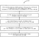
단계(212)에서, 커팅 블레이드를 가지고 있는 나이프 부재는 직선형 스테이플링 및 커팅 수술 기구의 하우징의 내부에 지지되어 있다. 하우징은 근위 단부와 원위 단부를 가진다. 커팅 블레이드는 나이프 부재가 원위방향으로 이동될 때 절단하도록 구성되어 있다. 단계(214)에서, 구동 부재는 제 1 위치로부터 제 2 위치로의 제 1 이동을 통하여 원위방향으로 이동된다.In step 212, a knife member having a cutting blade is supported inside the housing of straight stapling and cutting surgical instruments. The housing has a proximal end and a distal end. The cutting blade is configured to cut when the knife member is moved in the distal direction. In step 214, the drive member is moved distally through a first movement from the first position to the second position.
단계(216)에서, 나이프 부재는 나이프 부재가 원위방향으로 이동하는 것을 저지하기 위해서 구동 부재의 제 1 이동 동안 하우징과 연결된다. 여러 가지 실시예에서, 나이프 부재는 구동 부재의 원위방향으로의 약 4mm 이동 내내 원위방향으로 이동하는 것이 저지되어 있다. 여러 가지 실시예에서, 나이프 부재를 하우징과 연결하는 단계는 나이프 부재와 하우징 사이의 맞물림을 확고히 하기 위해서 구동 부재를 사용하는 단계를 포함한다. 여러 가지 실시예에서, 나이프 부재와 하우징 사이의 맞물림을 확고히 하기 위해서 구동 부재를 사용하는 단계는 구동 부재를 나이프 부재와 접속시키는 단계를 포함한다. 예를 들어, 나이프 부재는 제 1 돌출부를 포함할 수 있는데, 이 제 1 돌출부는 나이프 부재가 구동 부재의 제 1 이동 동안 원위방향으로 이동하는 것을 저지하기 위해서 하우징의 리셉터클과 구동 부재를 접속시킨다.In step 216, the knife member is connected with the housing during the first movement of the drive member to prevent the knife member from moving distally. In various embodiments, the knife member is inhibited from moving in the distal direction throughout about 4 mm movement of the drive member in the distal direction. In various embodiments, connecting the knife member with the housing includes using the drive member to secure engagement between the knife member and the housing. In various embodiments, using the drive member to secure engagement between the knife member and the housing includes connecting the drive member with the knife member. For example, the knife member may comprise a first protrusion, which connects the drive member with the receptacle of the housing to prevent the knife member from moving distally during the first movement of the drive member.
단계(218)에서, 구동 부재는 구동 부재의 제 2 위치로부터 제 3 위치로의 원위방향 제 2 이동 동안 나이프 부재를 원위방향으로 구동시키는데 사용된다. 여러 가지 실시예에서, 나이프 부재는 구동 특징부를 포함하는데, 이 구동 특징부는, 구동 부재의 제 1 이동 동안에는 구동 부재와 접속하지 않고 구동 부재의 제 2 이동 동안에는 구동 부재와 접속한다. 여러 가지 실시예에서, 나이프의 구동 특징부는 제 2 돌출부를 포함한다.In step 218, the drive member is used to drive the knife member distally during the distal second movement from the second position to the third position of the drive member. In various embodiments, the knife member comprises a drive feature, which drive feature does not connect with the drive member during the first movement of the drive member but with the drive member during the second movement of the drive member. In various embodiments, the drive feature of the knife includes a second protrusion.
단계(220)에서, 구동 부재는 구동 부재의 제 2 이동 동안 스테이플을 전개하는데 사용된다. 예를 들어, 구동 부재는 스테이플을 전개하는 스테이플 푸셔와 접속하는 경사 표면을 포함할 수 있다.In step 220, the drive member is used to deploy staples during the second movement of the drive member. For example, the drive member may include an inclined surface that connects with a staple pusher that deploys staples.
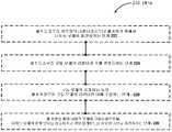
도 18에는 여러 가지 실시예에 따라서 방법(210)으로 달성될 수 있는 선택적인 단계가 나타나 있다. 선택적인 단계(222)에서, 나이프 부재는 제 1 돌출부를 하우징의 리셉터클로부터 제거하기 위해서 회전된다. 선택적인 단계(224)에서, 제 1 돌출부는 구동 부재의 리셉터클 속에 받아들여진다. 선택적인 단계(226)에서, 제 1 돌출부는 구동 부재의 제 2 이동 동안 구동 부재의 리셉터클 내에 수용된다. 선택적인 단계(228)에서, 나이프 부재는 캠 표면을 따라 구동되고, 이로써 나이프 부재의 원위 단부를 상승시키고 커팅 블레이드를 하우징 속으로 하강시킨다.18 illustrates optional steps that can be accomplished with the
본 명세서에 개시되어 있는 방법은 적합한 적용처에서 이용될 수 있다. 예를 들어, 본 명세서에 개시되어 있는 방법은 수술 기구에서 이용될 수 있는데, 이 수술 기구는 개방 또는 최소 침습(단일의 부위 또는 다수의 부위) 시술을 위하여 수동식 또는 동력공급식, 휴대용(hand-held) 또는 로봇식, 직접 제어식 또는 원격조종식일 수 있는 것이다.The methods disclosed herein can be used in suitable applications. For example, the methods disclosed herein can be used in surgical instruments, which are manual or powered, hand-held for open or minimally invasive (single or multiple site) procedures. held or robotic, direct controlled or remotely controlled.
다른 변경은 본 발명의 사상의 범위 내에 있다. 따라서, 본 발명은 여러 가지 수정과 대체 구성이 용이하지만, 도시된 특정 실시예는 도면에 나타나 있고 상술되어 있다. 그러나, 본 발명이 특정 형태나 개시되어 있는 형태로 제한되는 것은 의도되지 않았다는 것과, 본 발명이 첨부되는 특허청구범위에서 정의된 바와 같이 모든 수정사항, 대체 구성, 및 본 발명의 사상과 범위 내의 균등물을 내포할 수 있다는 것은 이해되어야 한다.Other variations are within the spirit of the invention. Thus, while the invention is susceptible to various modifications and alternative arrangements, the specific embodiments shown are shown in the drawings and described above. However, it is not intended that the invention be limited to the particular form or forms disclosed, and all modifications, alternative constructions, and equivalents within the spirit and scope of the invention, as defined in the appended claims. It should be understood that it can contain water.
"힘(force)"이라는 용어는 본 명세서에서 달리 지시되거나 문맥상 명백히 모순되지 않는다면 힘과 토크 모두를 포함(특히 다음에 오는 특허청구범위의 문맥상)하는 것으로 해석되어야 한다. "일(a, an)" 및 "그(the)"라는 용어와, 본 발명을 설명하는 문맥상 이에 유사한 지시대상의 사용(특히 다음에 오는 특허청구범위의 문맥상)은 본 명세서에서 달리 지시되거나 문맥상 명백히 모순되지 않는다면 단수와 복수 모두를 내포하는 것으로 해석되어야 한다. "구비하는(comprising)", "가지는(having)", "포함하는(including)", 및 "포함하고 있는(containing)"이라는 표현은 달리 언급되지 않는다면 개방형(open-ended) 표현(즉, "포함하지만 이에 제한되지 않는(including, but not limited to)"을 의미함)으로 해석되어야 한다. "연결되는(connected)"이라는 용어는, 개재되어 있는 무언가가 있는 경우라도 어딘가의 내부에 부분적으로 또는 전체적으로 포함되어 있거나, 어딘가에 부착되어 있거나, 무언가와 함께 결합되어 있는 것으로 해석되어야 한다. 본 명세서에서의 값의 범위에 대한 설명은 본 명세서에서 달리 지시되지 않는다면 범위 내의 각각의 별개의 값을 개별적으로 지칭하는 약술(shorthand) 방법으로 이용되도록 의도되었을 뿐이고, 각각의 별개의 값은 마치 본 명세서에서 개별적으로 설명되어 있는 것처럼 본 명세서 내부에 통합되어 있다. 본 명세서에 설명되어 있는 모든 방법은 본 명세서에서 달리 지시되거나 문맥상 명백히 모순되지 않는다면 적합한 순서로 실행될 수 있다. 본 명세서에 제공되어 있는 일부나 모든 실시예, 즉 예시적인 용어(예컨대, "~와 같은(such as)")는 본 발명의 실시예를 더욱 잘 설명하도록 의도되었을 뿐이고, 달리 주장되지 않는다면 본 발명의 범위를 제한하려는 것이 아니다. 본 명세서의 어떤 용어도 본 발명의 실시에 필수적일 정도로 주장되지 않는 구성요소를 지시하는 것으로서 해석되어서는 안된다.The term "force" is to be construed as including both force and torque (particularly in the context of the following claims) unless otherwise indicated herein or otherwise clearly contradicted by context. The terms "a, an" and "the", and the use of contextually similar indications (especially in the context of the claims that follow) that describe the invention, are otherwise indicated herein. It shall be construed as including both singular and plural unless it is contradictory or obviously contradictory in context. The expressions "comprising", "having", "including", and "containing" are open-ended expressions (ie, " In the sense of "including, but not limited to". The term " connected " should be construed as being partly or wholly contained within, attached to, or associated with something, even if there is something intervening. The description of the range of values herein is intended to be used only as a shorthand method of individually referring to each distinct value within the range unless otherwise indicated, and each distinct value is like this. It is incorporated within this specification as described separately in the specification. All methods described herein may be performed in a suitable order unless otherwise indicated herein or otherwise clearly contradicted by context. Some or all of the embodiments provided herein, ie, exemplary terms (eg, “such as”) are intended to better describe embodiments of the invention, and unless otherwise claimed, the invention It is not intended to limit the scope of. No terminology herein should be construed as indicating a component that is not claimed to the extent necessary for the practice of the invention.
본 발명의 바람직한 실시예는 본 명세서에 설명되어 있고, 본 발명을 실시하기 위하여 발명자에게 알려진 최선의 실시예를 포함한다. 전술한 설명을 이해할 수 있다면, 바람직한 실시예에 대한 변경은 당해 기술분야에서의 통상의 기술자에게 자명할 것이다. 본 발명에 의하면, 당해 기술분야에서의 통상의 기술자라면 이러한 변경을 적절히 이용할 수 있는 것을 예상할 수 있으며, 본 명세서에서 특히 설명되어 있는 것과 다른 방법으로 실시될 수 있다는 것을 알 수 있다. 따라서, 당해 발명에는 적용가능한 법률에 의하여 허용되는 바와 같이 본 명세서에 첨부되어 있는 특허청구범위에서 설명되는 본 발명의 균등물과 수정 모두가 포함된다. 더욱이, 본 명세서에서의 가능성 있는 모든 변경에서의 상술된 구성요소의 임의의 조합은, 본 명세서에서 달리 지시되고 있거나 문맥상 명백히 모순되지 않는다면 본 발명에 포함된다.Preferred embodiments of the invention are described herein and include the best embodiments known to the inventors for carrying out the invention. If the above description can be understood, modifications to the preferred embodiment will be apparent to those skilled in the art. According to the present invention, one skilled in the art can expect that such a change can be appropriately used, and it can be seen that it can be carried out in a manner different from that specifically described herein. Accordingly, the invention includes all equivalents and modifications of the invention described in the claims appended hereto as permitted by applicable law. Moreover, any combination of the above described elements in all possible variations herein is included in the present invention unless otherwise indicated herein or otherwise clearly contradicted by context.
본 명세서에서 인용되어 있는 공보, 특허 출원 및 특허를 포함하는 모든 참고문헌은, 각각의 참고문헌이 개별적으로 그리고 특정적으로 지시되거나 그 전체로서 설명되어 있는 것과 같은 정도로, 참조사항으로서 본 명세서에 통합되어 있다.All references, including publications, patent applications, and patents cited herein are hereby incorporated by reference to the same extent as if each reference was individually and specifically indicated or described in its entirety. It is.
Claims (24)
Translated fromKorean상기 방법은:
근위 단부와 원위 단부를 가지는 상기 수술 기구의 하우징 내부에 커팅 블레이드를 가지는 나이프 부재를 지지하는 단계로서, 상기 커팅 블레이드는 상기 나이프 부재가 원위방향으로 이동될 때 절단하도록 구성되는 단계;
구동 부재를 제 1 위치로부터 제 2 위치로의 제 1 이동을 통하여 원위방향으로 이동시키는 단계;
상기 나이프 부재가 원위방향으로 이동하는 것을 저지하기 위해서, 상기 구동 부재의 상기 제 1 이동 동안 상기 나이프 부재를 상기 하우징과 연결하는 단계;
상기 구동 부재의 상기 제 2 위치로부터 제 3 위치로의 원위방향 제 2 이동 동안 상기 나이프 부재를 원위방향으로 구동시키기 위해서, 상기 구동 부재를 사용하는 단계;를 구비하는 것을 특징으로 하는 방법.A method of articulating a cutting blade in a surgical instrument,
The method is:
Supporting a knife member having a cutting blade inside a housing of the surgical instrument having a proximal end and a distal end, the cutting blade configured to cut when the knife member is moved in the distal direction;
Moving the drive member distally through a first movement from the first position to the second position;
Coupling the knife member with the housing during the first movement of the drive member to prevent the knife member from moving distally;
Using the drive member to drive the knife member distally during the distal second movement from the second position to the third position of the drive member.
상기 나이프 부재는 상기 구동 부재의 원위방향으로의 약 4mm 이동 내내 원위방향으로 이동하는 것이 저지되어 있는 것을 특징으로 하는 방법.The method of claim 1,
And the knife member is prevented from moving in the distal direction throughout the movement of about 4 mm in the distal direction of the drive member.
상기 나이프 부재를 상기 하우징과 연결하는 상기 단계는, 상기 나이프 부재와 상기 하우징 사이의 맞물림을 확고히 하기 위해서 상기 구동 부재를 사용하는 단계를 포함하는 것을 특징으로 하는 방법.The method of claim 1,
Connecting the knife member with the housing comprises using the drive member to secure engagement between the knife member and the housing.
상기 나이프 부재와 상기 하우징 사이의 맞물림을 확고히 하기 위해서 상기 구동 부재를 사용하는 상기 단계는, 상기 구동 부재를 상기 나이프 부재와 접속시키는 단계를 포함하는 것을 특징으로 하는 방법.The method of claim 3, wherein
And said step of using said drive member to secure engagement between said knife member and said housing comprises connecting said drive member with said knife member.
상기 나이프 부재는, 상기 나이프 부재가 상기 구동 부재의 제 1 이동 동안 원위방향으로 이동하는 것을 저지하기 위해서 상기 하우징의 리셉터클 및 상기 구동 부재와 접속하고 있는, 제 1 돌출부를 포함하는 것을 특징으로 하는 방법.The method of claim 4, wherein
And the knife member comprises a first protrusion in contact with the receptacle of the housing and the drive member to prevent the knife member from moving distally during the first movement of the drive member. .
상기 제 1 돌출부를 상기 하우징의 리셉터클로부터 제거하기 위해서 상기 나이프 부재를 회전시키는 단계를 더 구비하는 방법.The method of claim 5,
Rotating the knife member to remove the first protrusion from the receptacle of the housing.
상기 제 1 돌출부를 상기 구동 부재의 리셉터클 속에 받아들이는 단계; 및
상기 구동 부재의 제 2 이동 동안 상기 제 1 돌출부를 상기 구동 부재의 리셉터클 내에 수용하는 단계;를 더 구비하는 방법.The method of claim 6,
Receiving the first protrusion into a receptacle of the drive member; And
Receiving the first protrusion in a receptacle of the drive member during a second movement of the drive member.
상기 나이프 부재는 상기 구동 부재의 제 1 이동 동안 상기 구동 부재와 접속하지 않고 상기 구동 부재의 제 2 이동 동안 상기 구동 부재와 접속하는 구동 특징부를 포함하는 것을 특징으로 하는 방법.The method of claim 1,
And the knife member includes a drive feature to contact the drive member during a second movement of the drive member without contacting the drive member during the first movement of the drive member.
상기 나이프의 구동 특징부는 제 2 돌출부를 포함하는 것을 특징으로 하는 방법.The method of claim 8,
And the drive feature of the knife comprises a second protrusion.
상기 나이프 부재를 캠 표면을 따라 구동시킴으로써, 상기 나이프 부재의 원위 단부를 상승시키고 상기 커팅 블레이드를 상기 하우징 속으로 하강시키는 단계를 더 구비하는 것을 특징으로 하는 방법.The method of claim 1,
Driving the knife member along the cam surface to raise the distal end of the knife member and to lower the cutting blade into the housing.
상기 구동 부재의 제 2 이동 동안 스테이플들을 전개하기 위해서 상기 구동 부재를 사용하는 단계를 더 구비하는 것을 특징으로 하는 방법.The method of claim 1,
And using the drive member to deploy staples during the second movement of the drive member.
상기 샤프트 원위 단부에 연결되고 반대편에 있는 죠들을 포함하는 엔드 이펙터;
상기 죠들 중 하나에 포함되어 있는 하우징;
원위방향으로의 이동을 위하여 상기 하우징 내부에서 지지되는 나이프 부재; 및
원위방향으로의 이동을 위하여 상기 하우징 내부에 미끄럼이동가능하게 장착되는 구동 부재;를 구비하고,
상기 하우징은 하우징 근위 단부, 하우징 원위 단부, 상기 하우징 근위 단부와 하우징 원위 단부 사이에 뻗어 있는 상부 표면, 상기 하우징 근위 단부와 하우징 원위 단부 사이에 뻗어 있는 중앙 캐비티, 및 상기 상부 표면을 통과하여 뻗어 있는 길이방향 슬롯을 포함하고,
상기 나이프 부재는 상기 나이프 부재가 원위방향으로 이동될 때 절단하도록 구성되어 있는 커팅 블레이드를 가지고,
상기 나이프 부재는, 상기 나이프 부재가 원위방향으로 이동하는 것을 저지하기 위해서, 상기 구동 부재의 제 1 위치로부터 제 2 위치로 원위방향으로의 제 1 이동 동안 상기 하우징과 연결되고, 상기 구동 부재의 제 2 위치로부터 제 3 위치로의 원위방향으로의 제 2 이동 동안 상기 구동 부재에 의하여 원위방향으로 구동되는 것을 특징으로 하는 수술 기구.An elongated shaft having a shaft distal end and a shaft proximal end;
An end effector connected to the shaft distal end and including opposite jaws;
A housing included in one of the jaws;
A knife member supported inside the housing for movement in the distal direction; And
And a drive member slidably mounted in the housing for movement in the distal direction.
The housing has a housing proximal end, a housing distal end, an upper surface extending between the housing proximal end and the housing distal end, a central cavity extending between the housing proximal end and the housing distal end, and extending through the upper surface. Including a longitudinal slot,
The knife member has a cutting blade configured to cut when the knife member is moved in a distal direction,
The knife member is connected with the housing during the first movement in the distal direction from the first position to the second position of the drive member to prevent the knife member from moving in the distal direction, And the distal direction is driven by the drive member during a second movement in a distal direction from a second position to a third position.
상기 나이프 부재는 상기 구동 부재의 원위방향으로의 약 4mm 이동 내내 원위방향으로의 이동이 저지되는 것을 특징으로 하는 수술 기구.The method of claim 12,
The knife member is surgical instrument, characterized in that movement in the distal direction is inhibited throughout the movement of about 4 mm in the distal direction of the drive member.
상기 구동 부재는, 상기 나이프 부재가 원위방향으로 이동하는 것을 저지하기 위해서, 상기 구동 부재의 제 1 이동 동안 상기 나이프 부재와 하우징 사이의 맞물림을 확고히 하는데 사용되는 것을 특징으로 하는 수술 기구.The method of claim 12,
And the drive member is used to secure engagement between the knife member and the housing during the first movement of the drive member to prevent movement of the knife member in the distal direction.
상기 구동 부재는, 상기 나이프 부재가 원위방향으로 이동하는 것을 저지하기 위해서, 상기 구동 부재의 제 1 이동 동안 상기 나이프 부재와 하우징 사이의 맞물림을 확고히 하기 위해서 상기 나이프 부재와 접속하는 것을 특징으로 하는 수술 기구.The method of claim 14,
The drive member is in contact with the knife member to secure engagement between the knife member and the housing during the first movement of the drive member to prevent movement of the knife member in the distal direction. Instrument.
상기 나이프 부재는, 상기 나이프 부재가 상기 구동 부재의 제 1 이동 동안 원위방향으로 이동하는 것을 저지하기 위해서 상기 하우징의 리셉터클 및 상기 구동 부재와 접속하고 있는, 제 1 돌출부를 포함하는 것을 특징으로 하는 수술 기구.The method of claim 15,
And the knife member comprises a first protrusion, which is in contact with the receptacle of the housing and the drive member to prevent the knife member from moving distally during the first movement of the drive member. Instrument.
상기 나이프 부재는 상기 구동 부재가 상기 제 3 위치에 도달하기 전에 상기 하우징의 리셉터클로부터 상기 제 1 돌출부를 제거하기 위해서 회전되는 것을 특징으로 하는 수술 기구.The method of claim 16,
And the knife member is rotated to remove the first protrusion from the receptacle of the housing before the drive member reaches the third position.
상기 구동 부재의 리셉터클은, 상기 제 1 돌출부를 받아들이고 상기 구동 부재의 제 2 이동 동안 상기 제 1 돌출부를 수용하도록 구성되어 있는 것을 특징으로 하는 수술 기구.The method of claim 17,
And the receptacle of the drive member is configured to receive the first protrusion and to receive the first protrusion during a second movement of the drive member.
상기 나이프 부재는 구동 특징부를 포함하고, 상기 구동 부재는, 상기 구동 부재의 제 1 이동 동안에는 상기 구동 특징부와 접속하지 않고, 상기 구동 부재의 제 2 이동 동안에는 상기 나이프 부재를 원위방향으로 구동시키기 위해서 상기 구동 특징부와 접속하고 있는 것을 특징을 하는 수술 기구.The method of claim 12,
The knife member includes a drive feature, wherein the drive member does not connect with the drive feature during the first movement of the drive member and to drive the knife member distally during the second movement of the drive member. And a surgical instrument in communication with the drive feature.
상기 구동 특징부는 제 2 돌출부를 포함하는 것을 특징으로 하는 수술 기구.The method of claim 19,
And the drive feature includes a second protrusion.
상기 구동 부재가 상기 제 3 위치로부터 제 4 위치로의 제 3 이동을 통하여 원위방향으로 이동되어 상기 나이프 부재의 원위 단부를 상승시키고 상기 커팅 블레이드를 상기 하우징 속으로 하강시킬 때, 상기 나이프 부재와 접속하도록 구성되어 있는 캠 표면을 구비하는 것을 특징으로 하는 수술 기구.The method of claim 12,
When the drive member is moved distally through a third movement from the third position to the fourth position to raise the distal end of the knife member and to lower the cutting blade into the housing. And a cam surface configured to:
상기 하우징은 상기 상부 표면과 상기 중앙 캐비티 사이에 뻗어 있는 복수 개의 스테이플 개구부를 포함하고, 상기 수술 기구는 상기 스테이플 개구부들 내에 배치되어 있는 복수 개의 스테이플을 구비하고, 상기 스테이플 각각은 상기 구동 부재의 원위방향으로의 이동에 응답하여 전개되는 것을 특징으로 하는 수술 기구.The method of claim 12,
The housing includes a plurality of staple openings extending between the upper surface and the central cavity, the surgical instrument having a plurality of staples disposed within the staple openings, each of the staples distal of the drive member. Surgical instruments that are deployed in response to movement in the direction.
상기 카트리지는:
상기 수술 기구의 엔드 이펙터에 탈착가능한 하우징;
상기 하우징에 대하여 회전시키기 위하여 상기 하우징과 연결되어 있는 리드 스크루;
상기 리드 스크루와 회전가능하게 연결되어 있는 회전 입력부;
원위방향으로의 이동을 위하여 상기 하우징 내부에 지지되어 있는 나이프 부재; 및
상기 리드 스크루의 회전에 응답하여 상기 리드 스크루를 따르는 이동을 위하여 상기 하우징 내에 장착되어 있고 상기 리드 스크루와 연결되어 있는 구동 부재;를 구비하고,
상기 하우징은 근위 단부, 원위 단부, 상기 근위 단부와 상기 원위 단부 사이에 뻗어 있는 상부 표면, 상기 근위 단부와 원위 단부 사이에 뻗어 있는 중앙 캐비티, 및 상기 상부 표면을 통과하여 뻗어 있는 길이방향 슬롯을 포함하고,
상기 회전 입력부는 상기 하우징이 상기 엔드 이펙터에 부착되어 있을 때 상기 수술 기구의 회전 출력부와 연결되도록 구성되어 있고,
상기 나이프 부재는, 상기 나이프 부재가 원위방향으로 이동될 때 절단하도록 구성되어 있는 커팅 블레이드를 가지고,
상기 나이프 부재는, 상기 나이프 부재가 원위방향으로 이동하는 것을 저지하기 위해서 상기 구동 부재의 제 1 위치로부터 제 2 위치로의 원위방향으로의 제 1 이동 동안 상기 하우징과 연결되고, 상기 구동 부재의 상기 제 2 위치로부터 제 3위치로의 원위방향으로의 제 2 이동 동안 상기 구동 부재에 의해 원위방향으로 구동되는 것을 특징으로 하는 카트리지.A removable cartridge of a surgical instrument,
The cartridge is:
A housing detachable to an end effector of the surgical instrument;
A lead screw connected to the housing to rotate relative to the housing;
A rotation input unit rotatably connected to the lead screw;
A knife member supported inside the housing for movement in the distal direction; And
And a drive member mounted in the housing and connected to the lead screw for movement along the lead screw in response to rotation of the lead screw,
The housing includes a proximal end, a distal end, an upper surface extending between the proximal end and the distal end, a central cavity extending between the proximal end and the distal end, and a longitudinal slot extending through the upper surface. and,
The rotation input is configured to be connected to the rotation output of the surgical instrument when the housing is attached to the end effector,
The knife member has a cutting blade configured to cut when the knife member is moved in a distal direction,
The knife member is connected with the housing during a first movement in a distal direction from the first position to the second position of the drive member to prevent the knife member from moving in the distal direction, A cartridge, which is driven distally by the drive member during a second movement in a distal direction from a second position to a third position.
상기 하우징은 상기 상부 표면과 상기 중앙 캐비티 사이에 뻗어 있는 복수개의 스테이플 개구부를 포함하고, 상기 카트리지는 상기 스테이플 개구부들에 배치되어 있는 복수 개의 스테이플을 더 구비하고, 상기 스테이플 각각은 상기 구동 부재의 원위방향으로의 이동에 응답하여 전개되는 것을 특징으로 하는 카트리지.The method of claim 23,
The housing includes a plurality of staple openings extending between the upper surface and the central cavity, wherein the cartridge further comprises a plurality of staples disposed in the staple openings, each of the staples distal of the drive member. A cartridge characterized in that it is deployed in response to movement in a direction.
Applications Claiming Priority (3)
| Application Number | Priority Date | Filing Date | Title |
|---|---|---|---|
| US201161551876P | 2011-10-26 | 2011-10-26 | |
| US61/551,876 | 2011-10-26 | ||
| PCT/US2012/062302WO2013063525A1 (en) | 2011-10-26 | 2012-10-26 | Surgical instrument with integral knife blade |
Related Child Applications (1)
| Application Number | Title | Priority Date | Filing Date |
|---|---|---|---|
| KR1020197025844ADivisionKR102073600B1 (en) | 2011-10-26 | 2012-10-26 | Surgical instrument with integral knife blade |
Publications (2)
| Publication Number | Publication Date |
|---|---|
| KR20140079785A KR20140079785A (en) | 2014-06-27 |
| KR102019754B1true KR102019754B1 (en) | 2019-09-10 |
Family
ID=48168614
Family Applications (2)
| Application Number | Title | Priority Date | Filing Date |
|---|---|---|---|
| KR1020147010488AActiveKR102019754B1 (en) | 2011-10-26 | 2012-10-26 | Surgical instrument with integral knife blade |
| KR1020197025844AActiveKR102073600B1 (en) | 2011-10-26 | 2012-10-26 | Surgical instrument with integral knife blade |
Family Applications After (1)
| Application Number | Title | Priority Date | Filing Date |
|---|---|---|---|
| KR1020197025844AActiveKR102073600B1 (en) | 2011-10-26 | 2012-10-26 | Surgical instrument with integral knife blade |
Country Status (6)
| Country | Link |
|---|---|
| US (3) | US9924941B2 (en) |
| EP (3) | EP4154829B1 (en) |
| JP (1) | JP6210994B2 (en) |
| KR (2) | KR102019754B1 (en) |
| CN (2) | CN107348981B (en) |
| WO (1) | WO2013063525A1 (en) |
Families Citing this family (752)
| Publication number | Priority date | Publication date | Assignee | Title |
|---|---|---|---|---|
| US5865361A (en) | 1997-09-23 | 1999-02-02 | United States Surgical Corporation | Surgical stapling apparatus |
| US9060770B2 (en) | 2003-05-20 | 2015-06-23 | Ethicon Endo-Surgery, Inc. | Robotically-driven surgical instrument with E-beam driver |
| US20070084897A1 (en) | 2003-05-20 | 2007-04-19 | Shelton Frederick E Iv | Articulating surgical stapling instrument incorporating a two-piece e-beam firing mechanism |
| US11998198B2 (en) | 2004-07-28 | 2024-06-04 | Cilag Gmbh International | Surgical stapling instrument incorporating a two-piece E-beam firing mechanism |
| US9072535B2 (en) | 2011-05-27 | 2015-07-07 | Ethicon Endo-Surgery, Inc. | Surgical stapling instruments with rotatable staple deployment arrangements |
| US8215531B2 (en) | 2004-07-28 | 2012-07-10 | Ethicon Endo-Surgery, Inc. | Surgical stapling instrument having a medical substance dispenser |
| US11890012B2 (en) | 2004-07-28 | 2024-02-06 | Cilag Gmbh International | Staple cartridge comprising cartridge body and attached support |
| US7934630B2 (en) | 2005-08-31 | 2011-05-03 | Ethicon Endo-Surgery, Inc. | Staple cartridges for forming staples having differing formed staple heights |
| US9237891B2 (en) | 2005-08-31 | 2016-01-19 | Ethicon Endo-Surgery, Inc. | Robotically-controlled surgical stapling devices that produce formed staples having different lengths |
| US11484312B2 (en) | 2005-08-31 | 2022-11-01 | Cilag Gmbh International | Staple cartridge comprising a staple driver arrangement |
| US10159482B2 (en) | 2005-08-31 | 2018-12-25 | Ethicon Llc | Fastener cartridge assembly comprising a fixed anvil and different staple heights |
| US11246590B2 (en) | 2005-08-31 | 2022-02-15 | Cilag Gmbh International | Staple cartridge including staple drivers having different unfired heights |
| US7669746B2 (en) | 2005-08-31 | 2010-03-02 | Ethicon Endo-Surgery, Inc. | Staple cartridges for forming staples having differing formed staple heights |
| US20070106317A1 (en) | 2005-11-09 | 2007-05-10 | Shelton Frederick E Iv | Hydraulically and electrically actuated articulation joints for surgical instruments |
| US11224427B2 (en) | 2006-01-31 | 2022-01-18 | Cilag Gmbh International | Surgical stapling system including a console and retraction assembly |
| US8186555B2 (en) | 2006-01-31 | 2012-05-29 | Ethicon Endo-Surgery, Inc. | Motor-driven surgical cutting and fastening instrument with mechanical closure system |
| US20110295295A1 (en) | 2006-01-31 | 2011-12-01 | Ethicon Endo-Surgery, Inc. | Robotically-controlled surgical instrument having recording capabilities |
| US20120292367A1 (en) | 2006-01-31 | 2012-11-22 | Ethicon Endo-Surgery, Inc. | Robotically-controlled end effector |
| US8708213B2 (en) | 2006-01-31 | 2014-04-29 | Ethicon Endo-Surgery, Inc. | Surgical instrument having a feedback system |
| US7845537B2 (en) | 2006-01-31 | 2010-12-07 | Ethicon Endo-Surgery, Inc. | Surgical instrument having recording capabilities |
| US8820603B2 (en) | 2006-01-31 | 2014-09-02 | Ethicon Endo-Surgery, Inc. | Accessing data stored in a memory of a surgical instrument |
| US11278279B2 (en) | 2006-01-31 | 2022-03-22 | Cilag Gmbh International | Surgical instrument assembly |
| US20110024477A1 (en) | 2009-02-06 | 2011-02-03 | Hall Steven G | Driven Surgical Stapler Improvements |
| US11793518B2 (en) | 2006-01-31 | 2023-10-24 | Cilag Gmbh International | Powered surgical instruments with firing system lockout arrangements |
| US7753904B2 (en) | 2006-01-31 | 2010-07-13 | Ethicon Endo-Surgery, Inc. | Endoscopic surgical instrument with a handle that can articulate with respect to the shaft |
| US8992422B2 (en) | 2006-03-23 | 2015-03-31 | Ethicon Endo-Surgery, Inc. | Robotically-controlled endoscopic accessory channel |
| EP2018248B1 (en) | 2006-05-19 | 2015-11-04 | Applied Medical Resources Corporation | Surgical stapler |
| US8322455B2 (en) | 2006-06-27 | 2012-12-04 | Ethicon Endo-Surgery, Inc. | Manually driven surgical cutting and fastening instrument |
| US10568652B2 (en) | 2006-09-29 | 2020-02-25 | Ethicon Llc | Surgical staples having attached drivers of different heights and stapling instruments for deploying the same |
| US11980366B2 (en) | 2006-10-03 | 2024-05-14 | Cilag Gmbh International | Surgical instrument |
| US8584921B2 (en) | 2006-10-06 | 2013-11-19 | Covidien Lp | Surgical instrument with articulating tool assembly |
| US8684253B2 (en) | 2007-01-10 | 2014-04-01 | Ethicon Endo-Surgery, Inc. | Surgical instrument with wireless communication between a control unit of a robotic system and remote sensor |
| US8632535B2 (en) | 2007-01-10 | 2014-01-21 | Ethicon Endo-Surgery, Inc. | Interlock and surgical instrument including same |
| US11291441B2 (en) | 2007-01-10 | 2022-04-05 | Cilag Gmbh International | Surgical instrument with wireless communication between control unit and remote sensor |
| US20080169333A1 (en) | 2007-01-11 | 2008-07-17 | Shelton Frederick E | Surgical stapler end effector with tapered distal end |
| US11039836B2 (en) | 2007-01-11 | 2021-06-22 | Cilag Gmbh International | Staple cartridge for use with a surgical stapling instrument |
| US7673782B2 (en) | 2007-03-15 | 2010-03-09 | Ethicon Endo-Surgery, Inc. | Surgical stapling instrument having a releasable buttress material |
| US8931682B2 (en) | 2007-06-04 | 2015-01-13 | Ethicon Endo-Surgery, Inc. | Robotically-controlled shaft based rotary drive systems for surgical instruments |
| US11564682B2 (en) | 2007-06-04 | 2023-01-31 | Cilag Gmbh International | Surgical stapler device |
| US7753245B2 (en) | 2007-06-22 | 2010-07-13 | Ethicon Endo-Surgery, Inc. | Surgical stapling instruments |
| US11849941B2 (en) | 2007-06-29 | 2023-12-26 | Cilag Gmbh International | Staple cartridge having staple cavities extending at a transverse angle relative to a longitudinal cartridge axis |
| US8061576B2 (en) | 2007-08-31 | 2011-11-22 | Tyco Healthcare Group Lp | Surgical instrument |
| US11986183B2 (en) | 2008-02-14 | 2024-05-21 | Cilag Gmbh International | Surgical cutting and fastening instrument comprising a plurality of sensors to measure an electrical parameter |
| US7819298B2 (en) | 2008-02-14 | 2010-10-26 | Ethicon Endo-Surgery, Inc. | Surgical stapling apparatus with control features operable with one hand |
| US8758391B2 (en) | 2008-02-14 | 2014-06-24 | Ethicon Endo-Surgery, Inc. | Interchangeable tools for surgical instruments |
| US9179912B2 (en) | 2008-02-14 | 2015-11-10 | Ethicon Endo-Surgery, Inc. | Robotically-controlled motorized surgical cutting and fastening instrument |
| US8636736B2 (en) | 2008-02-14 | 2014-01-28 | Ethicon Endo-Surgery, Inc. | Motorized surgical cutting and fastening instrument |
| JP5410110B2 (en) | 2008-02-14 | 2014-02-05 | エシコン・エンド−サージェリィ・インコーポレイテッド | Surgical cutting / fixing instrument with RF electrode |
| US7866527B2 (en) | 2008-02-14 | 2011-01-11 | Ethicon Endo-Surgery, Inc. | Surgical stapling apparatus with interlockable firing system |
| US8573465B2 (en) | 2008-02-14 | 2013-11-05 | Ethicon Endo-Surgery, Inc. | Robotically-controlled surgical end effector system with rotary actuated closure systems |
| US9585657B2 (en) | 2008-02-15 | 2017-03-07 | Ethicon Endo-Surgery, Llc | Actuator for releasing a layer of material from a surgical end effector |
| US11648005B2 (en) | 2008-09-23 | 2023-05-16 | Cilag Gmbh International | Robotically-controlled motorized surgical instrument with an end effector |
| US9386983B2 (en) | 2008-09-23 | 2016-07-12 | Ethicon Endo-Surgery, Llc | Robotically-controlled motorized surgical instrument |
| US8210411B2 (en) | 2008-09-23 | 2012-07-03 | Ethicon Endo-Surgery, Inc. | Motor-driven surgical cutting instrument |
| US8628544B2 (en) | 2008-09-23 | 2014-01-14 | Covidien Lp | Knife bar for surgical instrument |
| US9005230B2 (en) | 2008-09-23 | 2015-04-14 | Ethicon Endo-Surgery, Inc. | Motorized surgical instrument |
| US7988028B2 (en) | 2008-09-23 | 2011-08-02 | Tyco Healthcare Group Lp | Surgical instrument having an asymmetric dynamic clamping member |
| US8608045B2 (en) | 2008-10-10 | 2013-12-17 | Ethicon Endo-Sugery, Inc. | Powered surgical cutting and stapling apparatus with manually retractable firing system |
| US8517239B2 (en) | 2009-02-05 | 2013-08-27 | Ethicon Endo-Surgery, Inc. | Surgical stapling instrument comprising a magnetic element driver |
| RU2525225C2 (en) | 2009-02-06 | 2014-08-10 | Этикон Эндо-Серджери, Инк. | Improvement of drive surgical suturing instrument |
| US8851354B2 (en) | 2009-12-24 | 2014-10-07 | Ethicon Endo-Surgery, Inc. | Surgical cutting instrument that analyzes tissue thickness |
| US8220688B2 (en) | 2009-12-24 | 2012-07-17 | Ethicon Endo-Surgery, Inc. | Motor-driven surgical cutting instrument with electric actuator directional control assembly |
| US8783543B2 (en) | 2010-07-30 | 2014-07-22 | Ethicon Endo-Surgery, Inc. | Tissue acquisition arrangements and methods for surgical stapling devices |
| US9629814B2 (en) | 2010-09-30 | 2017-04-25 | Ethicon Endo-Surgery, Llc | Tissue thickness compensator configured to redistribute compressive forces |
| US11298125B2 (en) | 2010-09-30 | 2022-04-12 | Cilag Gmbh International | Tissue stapler having a thickness compensator |
| US9386988B2 (en) | 2010-09-30 | 2016-07-12 | Ethicon End-Surgery, LLC | Retainer assembly including a tissue thickness compensator |
| US11925354B2 (en) | 2010-09-30 | 2024-03-12 | Cilag Gmbh International | Staple cartridge comprising staples positioned within a compressible portion thereof |
| US9016542B2 (en) | 2010-09-30 | 2015-04-28 | Ethicon Endo-Surgery, Inc. | Staple cartridge comprising compressible distortion resistant components |
| US10945731B2 (en) | 2010-09-30 | 2021-03-16 | Ethicon Llc | Tissue thickness compensator comprising controlled release and expansion |
| US11812965B2 (en) | 2010-09-30 | 2023-11-14 | Cilag Gmbh International | Layer of material for a surgical end effector |
| US9351730B2 (en) | 2011-04-29 | 2016-05-31 | Ethicon Endo-Surgery, Llc | Tissue thickness compensator comprising channels |
| US9788834B2 (en) | 2010-09-30 | 2017-10-17 | Ethicon Llc | Layer comprising deployable attachment members |
| US12213666B2 (en) | 2010-09-30 | 2025-02-04 | Cilag Gmbh International | Tissue thickness compensator comprising layers |
| US8695866B2 (en) | 2010-10-01 | 2014-04-15 | Ethicon Endo-Surgery, Inc. | Surgical instrument having a power control circuit |
| US9211122B2 (en) | 2011-03-14 | 2015-12-15 | Ethicon Endo-Surgery, Inc. | Surgical access devices with anvil introduction and specimen retrieval structures |
| AU2012250197B2 (en) | 2011-04-29 | 2017-08-10 | Ethicon Endo-Surgery, Inc. | Staple cartridge comprising staples positioned within a compressible portion thereof |
| US11207064B2 (en) | 2011-05-27 | 2021-12-28 | Cilag Gmbh International | Automated end effector component reloading system for use with a robotic system |
| KR102019754B1 (en) | 2011-10-26 | 2019-09-10 | 인튜어티브 서지컬 오퍼레이션즈 인코포레이티드 | Surgical instrument with integral knife blade |
| CN111281457B (en) | 2011-11-15 | 2023-10-20 | 直观外科手术操作公司 | Surgical instrument with retracting blade |
| US8740036B2 (en) | 2011-12-01 | 2014-06-03 | Covidien Lp | Surgical instrument with actuator spring arm |
| US9044230B2 (en) | 2012-02-13 | 2015-06-02 | Ethicon Endo-Surgery, Inc. | Surgical cutting and fastening instrument with apparatus for determining cartridge and firing motion status |
| BR112014024098B1 (en) | 2012-03-28 | 2021-05-25 | Ethicon Endo-Surgery, Inc. | staple cartridge |
| JP6224070B2 (en) | 2012-03-28 | 2017-11-01 | エシコン・エンド−サージェリィ・インコーポレイテッドEthicon Endo−Surgery,Inc. | Retainer assembly including tissue thickness compensator |
| MX358135B (en) | 2012-03-28 | 2018-08-06 | Ethicon Endo Surgery Inc | Tissue thickness compensator comprising a plurality of layers. |
| US11871901B2 (en) | 2012-05-20 | 2024-01-16 | Cilag Gmbh International | Method for situational awareness for surgical network or surgical network connected device capable of adjusting function based on a sensed situation or usage |
| US9101358B2 (en) | 2012-06-15 | 2015-08-11 | Ethicon Endo-Surgery, Inc. | Articulatable surgical instrument comprising a firing drive |
| US9289256B2 (en) | 2012-06-28 | 2016-03-22 | Ethicon Endo-Surgery, Llc | Surgical end effectors having angled tissue-contacting surfaces |
| JP6290201B2 (en) | 2012-06-28 | 2018-03-07 | エシコン・エンド−サージェリィ・インコーポレイテッドEthicon Endo−Surgery,Inc. | Lockout for empty clip cartridge |
| US12383267B2 (en) | 2012-06-28 | 2025-08-12 | Cilag Gmbh International | Robotically powered surgical device with manually-actuatable reversing system |
| US9408606B2 (en) | 2012-06-28 | 2016-08-09 | Ethicon Endo-Surgery, Llc | Robotically powered surgical device with manually-actuatable reversing system |
| US11278284B2 (en)* | 2012-06-28 | 2022-03-22 | Cilag Gmbh International | Rotary drive arrangements for surgical instruments |
| US9282974B2 (en) | 2012-06-28 | 2016-03-15 | Ethicon Endo-Surgery, Llc | Empty clip cartridge lockout |
| BR112014032776B1 (en) | 2012-06-28 | 2021-09-08 | Ethicon Endo-Surgery, Inc | SURGICAL INSTRUMENT SYSTEM AND SURGICAL KIT FOR USE WITH A SURGICAL INSTRUMENT SYSTEM |
| US20140001231A1 (en) | 2012-06-28 | 2014-01-02 | Ethicon Endo-Surgery, Inc. | Firing system lockout arrangements for surgical instruments |
| JP6297060B2 (en) | 2012-12-31 | 2018-03-20 | インテュイティブ サージカル オペレーションズ, インコーポレイテッド | Surgical staple cartridge with enhanced knife clearance |
| BR112015021082B1 (en) | 2013-03-01 | 2022-05-10 | Ethicon Endo-Surgery, Inc | surgical instrument |
| RU2672520C2 (en) | 2013-03-01 | 2018-11-15 | Этикон Эндо-Серджери, Инк. | Hingedly turnable surgical instruments with conducting ways for signal transfer |
| US12161322B2 (en) | 2013-03-13 | 2024-12-10 | Covidien Lp | Surgical stapling apparatus |
| US9629628B2 (en) | 2013-03-13 | 2017-04-25 | Covidien Lp | Surgical stapling apparatus |
| US9668729B2 (en) | 2013-03-13 | 2017-06-06 | Covidien Lp | Surgical stapling apparatus |
| US9717498B2 (en) | 2013-03-13 | 2017-08-01 | Covidien Lp | Surgical stapling apparatus |
| US9814463B2 (en) | 2013-03-13 | 2017-11-14 | Covidien Lp | Surgical stapling apparatus |
| EP2967564B1 (en) | 2013-03-14 | 2018-09-12 | Applied Medical Resources Corporation | Surgical stapler with partial pockets |
| US9629629B2 (en) | 2013-03-14 | 2017-04-25 | Ethicon Endo-Surgey, LLC | Control systems for surgical instruments |
| US9808244B2 (en) | 2013-03-14 | 2017-11-07 | Ethicon Llc | Sensor arrangements for absolute positioning system for surgical instruments |
| KR102526549B1 (en) | 2013-03-15 | 2023-04-27 | 어플라이드 메디컬 리소시스 코포레이션 | Surgical stapler having actuation mechanism with rotatable shaft |
| US9820742B2 (en) | 2013-03-15 | 2017-11-21 | Applied Medical Resources Corporation | Surgical stapler with expandable jaw |
| US9826976B2 (en) | 2013-04-16 | 2017-11-28 | Ethicon Llc | Motor driven surgical instruments with lockable dual drive shafts |
| BR112015026109B1 (en) | 2013-04-16 | 2022-02-22 | Ethicon Endo-Surgery, Inc | surgical instrument |
| US10550918B2 (en) | 2013-08-15 | 2020-02-04 | Intuitive Surgical Operations, Inc. | Lever actuated gimbal plate |
| US9775609B2 (en) | 2013-08-23 | 2017-10-03 | Ethicon Llc | Tamper proof circuit for surgical instrument battery pack |
| MX369362B (en) | 2013-08-23 | 2019-11-06 | Ethicon Endo Surgery Llc | Firing member retraction devices for powered surgical instruments. |
| US9662108B2 (en) | 2013-08-30 | 2017-05-30 | Covidien Lp | Surgical stapling apparatus |
| CN105682568B (en) | 2013-11-04 | 2018-10-23 | 柯惠Lp公司 | Surgical fasteners bringing device |
| JP6366708B2 (en) | 2013-11-04 | 2018-08-01 | コヴィディエン リミテッド パートナーシップ | Surgical fastener application device |
| CN105682567B (en) | 2013-11-04 | 2021-09-10 | 柯惠Lp公司 | Surgical fastener applying apparatus |
| US9867613B2 (en) | 2013-12-19 | 2018-01-16 | Covidien Lp | Surgical staples and end effectors for deploying the same |
| ES2824426T3 (en)* | 2013-12-31 | 2021-05-12 | Touchstone International Medical Science Co Ltd | Linear cutting stapler |
| CN103690212B (en)* | 2013-12-31 | 2015-08-12 | 上海创亿医疗器械技术有限公司 | There is the surgical linear anastomat from changing cutter function |
| US9962161B2 (en) | 2014-02-12 | 2018-05-08 | Ethicon Llc | Deliverable surgical instrument |
| US9848874B2 (en) | 2014-02-14 | 2017-12-26 | Covidien Lp | Small diameter endoscopic stapler |
| US9707005B2 (en) | 2014-02-14 | 2017-07-18 | Ethicon Llc | Lockout mechanisms for surgical devices |
| US20150272580A1 (en) | 2014-03-26 | 2015-10-01 | Ethicon Endo-Surgery, Inc. | Verification of number of battery exchanges/procedure count |
| US10004497B2 (en) | 2014-03-26 | 2018-06-26 | Ethicon Llc | Interface systems for use with surgical instruments |
| US10013049B2 (en) | 2014-03-26 | 2018-07-03 | Ethicon Llc | Power management through sleep options of segmented circuit and wake up control |
| US12232723B2 (en) | 2014-03-26 | 2025-02-25 | Cilag Gmbh International | Systems and methods for controlling a segmented circuit |
| BR112016021943B1 (en) | 2014-03-26 | 2022-06-14 | Ethicon Endo-Surgery, Llc | SURGICAL INSTRUMENT FOR USE BY AN OPERATOR IN A SURGICAL PROCEDURE |
| US9757126B2 (en) | 2014-03-31 | 2017-09-12 | Covidien Lp | Surgical stapling apparatus with firing lockout mechanism |
| US10470768B2 (en) | 2014-04-16 | 2019-11-12 | Ethicon Llc | Fastener cartridge including a layer attached thereto |
| US20150297225A1 (en) | 2014-04-16 | 2015-10-22 | Ethicon Endo-Surgery, Inc. | Fastener cartridges including extensions having different configurations |
| US10327764B2 (en) | 2014-09-26 | 2019-06-25 | Ethicon Llc | Method for creating a flexible staple line |
| CN106456176B (en) | 2014-04-16 | 2019-06-28 | 伊西康内外科有限责任公司 | Fastener Cartridge Including Extensions With Different Configurations |
| BR112016023825B1 (en) | 2014-04-16 | 2022-08-02 | Ethicon Endo-Surgery, Llc | STAPLE CARTRIDGE FOR USE WITH A SURGICAL STAPLER AND STAPLE CARTRIDGE FOR USE WITH A SURGICAL INSTRUMENT |
| CN106456159B (en) | 2014-04-16 | 2019-03-08 | 伊西康内外科有限责任公司 | Fastener Cartridge Assembly and Nail Retainer Cover Arrangement |
| US9668733B2 (en) | 2014-04-21 | 2017-06-06 | Covidien Lp | Stapling device with features to prevent inadvertent firing of staples |
| US10080552B2 (en)* | 2014-04-21 | 2018-09-25 | Covidien Lp | Adapter assembly with gimbal for interconnecting electromechanical surgical devices and surgical loading units, and surgical systems thereof |
| US9861366B2 (en) | 2014-05-06 | 2018-01-09 | Covidien Lp | Ejecting assembly for a surgical stapler |
| EP3142569B1 (en) | 2014-05-15 | 2023-12-27 | Covidien LP | Surgical fastener applying apparatus |
| ES2861258T3 (en) | 2014-06-11 | 2021-10-06 | Applied Med Resources | Circumferential Shot Surgical Stapler |
| EP3178411B1 (en)* | 2014-08-04 | 2023-12-20 | Olympus Corporation | Surgical instrument |
| BR112017004361B1 (en) | 2014-09-05 | 2023-04-11 | Ethicon Llc | ELECTRONIC SYSTEM FOR A SURGICAL INSTRUMENT |
| US10135242B2 (en) | 2014-09-05 | 2018-11-20 | Ethicon Llc | Smart cartridge wake up operation and data retention |
| US11311294B2 (en) | 2014-09-05 | 2022-04-26 | Cilag Gmbh International | Powered medical device including measurement of closure state of jaws |
| KR102773368B1 (en) | 2014-09-15 | 2025-02-27 | 어플라이드 메디컬 리소시스 코포레이션 | Surgical stapler with self-adjusting staple height |
| US10105142B2 (en)* | 2014-09-18 | 2018-10-23 | Ethicon Llc | Surgical stapler with plurality of cutting elements |
| US11207127B2 (en)* | 2014-09-25 | 2021-12-28 | Covidien Lp | Surgical instruments facilitating replacement of disposable components and/or sterilization of reusable components |
| US11523821B2 (en) | 2014-09-26 | 2022-12-13 | Cilag Gmbh International | Method for creating a flexible staple line |
| CN107427300B (en) | 2014-09-26 | 2020-12-04 | 伊西康有限责任公司 | Surgical suture buttresses and auxiliary materials |
| US10076325B2 (en) | 2014-10-13 | 2018-09-18 | Ethicon Llc | Surgical stapling apparatus comprising a tissue stop |
| US9924944B2 (en) | 2014-10-16 | 2018-03-27 | Ethicon Llc | Staple cartridge comprising an adjunct material |
| US11141153B2 (en) | 2014-10-29 | 2021-10-12 | Cilag Gmbh International | Staple cartridges comprising driver arrangements |
| US10517594B2 (en) | 2014-10-29 | 2019-12-31 | Ethicon Llc | Cartridge assemblies for surgical staplers |
| US11504192B2 (en) | 2014-10-30 | 2022-11-22 | Cilag Gmbh International | Method of hub communication with surgical instrument systems |
| US9844376B2 (en) | 2014-11-06 | 2017-12-19 | Ethicon Llc | Staple cartridge comprising a releasable adjunct material |
| US10736636B2 (en) | 2014-12-10 | 2020-08-11 | Ethicon Llc | Articulatable surgical instrument system |
| MX389118B (en) | 2014-12-18 | 2025-03-20 | Ethicon Llc | SURGICAL INSTRUMENT WITH AN ANVIL THAT CAN BE SELECTIVELY MOVED ON A DISCRETE, NON-MOBILE AXIS RELATIVE TO A STAPLE CARTRIDGE. |
| US9943309B2 (en) | 2014-12-18 | 2018-04-17 | Ethicon Llc | Surgical instruments with articulatable end effectors and movable firing beam support arrangements |
| US9987000B2 (en) | 2014-12-18 | 2018-06-05 | Ethicon Llc | Surgical instrument assembly comprising a flexible articulation system |
| US9844374B2 (en) | 2014-12-18 | 2017-12-19 | Ethicon Llc | Surgical instrument systems comprising an articulatable end effector and means for adjusting the firing stroke of a firing member |
| US9844375B2 (en) | 2014-12-18 | 2017-12-19 | Ethicon Llc | Drive arrangements for articulatable surgical instruments |
| US10085748B2 (en) | 2014-12-18 | 2018-10-02 | Ethicon Llc | Locking arrangements for detachable shaft assemblies with articulatable surgical end effectors |
| US10039545B2 (en) | 2015-02-23 | 2018-08-07 | Covidien Lp | Double fire stapling |
| US10285698B2 (en) | 2015-02-26 | 2019-05-14 | Covidien Lp | Surgical apparatus |
| US10085749B2 (en) | 2015-02-26 | 2018-10-02 | Covidien Lp | Surgical apparatus with conductor strain relief |
| US11154301B2 (en) | 2015-02-27 | 2021-10-26 | Cilag Gmbh International | Modular stapling assembly |
| US10441279B2 (en) | 2015-03-06 | 2019-10-15 | Ethicon Llc | Multiple level thresholds to modify operation of powered surgical instruments |
| US10687806B2 (en) | 2015-03-06 | 2020-06-23 | Ethicon Llc | Adaptive tissue compression techniques to adjust closure rates for multiple tissue types |
| US9901342B2 (en) | 2015-03-06 | 2018-02-27 | Ethicon Endo-Surgery, Llc | Signal and power communication system positioned on a rotatable shaft |
| US10617412B2 (en) | 2015-03-06 | 2020-04-14 | Ethicon Llc | System for detecting the mis-insertion of a staple cartridge into a surgical stapler |
| US10245033B2 (en) | 2015-03-06 | 2019-04-02 | Ethicon Llc | Surgical instrument comprising a lockable battery housing |
| JP2020121162A (en) | 2015-03-06 | 2020-08-13 | エシコン エルエルシーEthicon LLC | Time dependent evaluation of sensor data to determine stability element, creep element and viscoelastic element of measurement |
| US9993248B2 (en) | 2015-03-06 | 2018-06-12 | Ethicon Endo-Surgery, Llc | Smart sensors with local signal processing |
| US10548504B2 (en) | 2015-03-06 | 2020-02-04 | Ethicon Llc | Overlaid multi sensor radio frequency (RF) electrode system to measure tissue compression |
| US10033308B2 (en)* | 2015-03-17 | 2018-07-24 | Intuitive Surgical Operations, Inc. | Systems and methods for motor torque compensation |
| US9918717B2 (en) | 2015-03-18 | 2018-03-20 | Covidien Lp | Pivot mechanism for surgical device |
| US10433844B2 (en) | 2015-03-31 | 2019-10-08 | Ethicon Llc | Surgical instrument with selectively disengageable threaded drive systems |
| US10463368B2 (en) | 2015-04-10 | 2019-11-05 | Covidien Lp | Endoscopic stapler |
| US10226239B2 (en)* | 2015-04-10 | 2019-03-12 | Covidien Lp | Adapter assembly with gimbal for interconnecting electromechanical surgical devices and surgical loading units, and surgical systems thereof |
| US10117650B2 (en) | 2015-05-05 | 2018-11-06 | Covidien Lp | Adapter assembly and loading units for surgical stapling devices |
| US10299789B2 (en) | 2015-05-05 | 2019-05-28 | Covidie LP | Adapter assembly for surgical stapling devices |
| US10039532B2 (en) | 2015-05-06 | 2018-08-07 | Covidien Lp | Surgical instrument with articulation assembly |
| CN107635481B (en) | 2015-05-25 | 2021-01-05 | 柯惠有限合伙公司 | Minor diameter surgical suturing device |
| US10172615B2 (en) | 2015-05-27 | 2019-01-08 | Covidien Lp | Multi-fire push rod stapling device |
| US10349941B2 (en) | 2015-05-27 | 2019-07-16 | Covidien Lp | Multi-fire lead screw stapling device |
| US10548599B2 (en) | 2015-07-20 | 2020-02-04 | Covidien Lp | Endoscopic stapler and staple |
| US9987012B2 (en) | 2015-07-21 | 2018-06-05 | Covidien Lp | Small diameter cartridge design for a surgical stapling instrument |
| US10064622B2 (en) | 2015-07-29 | 2018-09-04 | Covidien Lp | Surgical stapling loading unit with stroke counter and lockout |
| US11154300B2 (en) | 2015-07-30 | 2021-10-26 | Cilag Gmbh International | Surgical instrument comprising separate tissue securing and tissue cutting systems |
| US10045782B2 (en) | 2015-07-30 | 2018-08-14 | Covidien Lp | Surgical stapling loading unit with stroke counter and lockout |
| US10194913B2 (en)* | 2015-07-30 | 2019-02-05 | Ethicon Llc | Surgical instrument comprising systems for assuring the proper sequential operation of the surgical instrument |
| EP3331455B1 (en) | 2015-08-06 | 2019-10-09 | Applied Medical Resources Corporation | Surgical stapler having locking articulation joint |
| US10835249B2 (en) | 2015-08-17 | 2020-11-17 | Ethicon Llc | Implantable layers for a surgical instrument |
| US10238386B2 (en) | 2015-09-23 | 2019-03-26 | Ethicon Llc | Surgical stapler having motor control based on an electrical parameter related to a motor current |
| US10105139B2 (en) | 2015-09-23 | 2018-10-23 | Ethicon Llc | Surgical stapler having downstream current-based motor control |
| US10299878B2 (en) | 2015-09-25 | 2019-05-28 | Ethicon Llc | Implantable adjunct systems for determining adjunct skew |
| US10980539B2 (en) | 2015-09-30 | 2021-04-20 | Ethicon Llc | Implantable adjunct comprising bonded layers |
| US10478188B2 (en) | 2015-09-30 | 2019-11-19 | Ethicon Llc | Implantable layer comprising a constricted configuration |
| US11890015B2 (en) | 2015-09-30 | 2024-02-06 | Cilag Gmbh International | Compressible adjunct with crossing spacer fibers |
| US10433846B2 (en) | 2015-09-30 | 2019-10-08 | Ethicon Llc | Compressible adjunct with crossing spacer fibers |
| US10213204B2 (en) | 2015-10-02 | 2019-02-26 | Covidien Lp | Micro surgical instrument and loading unit for use therewith |
| US10772632B2 (en) | 2015-10-28 | 2020-09-15 | Covidien Lp | Surgical stapling device with triple leg staples |
| US10973517B2 (en) | 2015-11-13 | 2021-04-13 | Intuitive Surgical Operations, Inc. | Stapler with composite cardan and screw drive |
| US10595864B2 (en) | 2015-11-24 | 2020-03-24 | Covidien Lp | Adapter assembly for interconnecting electromechanical surgical devices and surgical loading units, and surgical systems thereof |
| US10111660B2 (en) | 2015-12-03 | 2018-10-30 | Covidien Lp | Surgical stapler flexible distal tip |
| US10265068B2 (en) | 2015-12-30 | 2019-04-23 | Ethicon Llc | Surgical instruments with separable motors and motor control circuits |
| US10368865B2 (en) | 2015-12-30 | 2019-08-06 | Ethicon Llc | Mechanisms for compensating for drivetrain failure in powered surgical instruments |
| US10292704B2 (en) | 2015-12-30 | 2019-05-21 | Ethicon Llc | Mechanisms for compensating for battery pack failure in powered surgical instruments |
| US10966717B2 (en) | 2016-01-07 | 2021-04-06 | Covidien Lp | Surgical fastener apparatus |
| US10660623B2 (en) | 2016-01-15 | 2020-05-26 | Covidien Lp | Centering mechanism for articulation joint |
| BR112018016098B1 (en) | 2016-02-09 | 2023-02-23 | Ethicon Llc | SURGICAL INSTRUMENT |
| US11213293B2 (en) | 2016-02-09 | 2022-01-04 | Cilag Gmbh International | Articulatable surgical instruments with single articulation link arrangements |
| US10349937B2 (en) | 2016-02-10 | 2019-07-16 | Covidien Lp | Surgical stapler with articulation locking mechanism |
| US10420559B2 (en) | 2016-02-11 | 2019-09-24 | Covidien Lp | Surgical stapler with small diameter endoscopic portion |
| US10448948B2 (en) | 2016-02-12 | 2019-10-22 | Ethicon Llc | Mechanisms for compensating for drivetrain failure in powered surgical instruments |
| US11224426B2 (en) | 2016-02-12 | 2022-01-18 | Cilag Gmbh International | Mechanisms for compensating for drivetrain failure in powered surgical instruments |
| US10413297B2 (en)* | 2016-04-01 | 2019-09-17 | Ethicon Llc | Surgical stapling system configured to apply annular rows of staples having different heights |
| US10420552B2 (en) | 2016-04-01 | 2019-09-24 | Ethicon Llc | Surgical stapling system configured to provide selective cutting of tissue |
| JP7010838B2 (en) | 2016-04-01 | 2022-01-26 | エシコン エルエルシー | Surgical staple fasteners |
| US11284890B2 (en) | 2016-04-01 | 2022-03-29 | Cilag Gmbh International | Circular stapling system comprising an incisable tissue support |
| US10531874B2 (en) | 2016-04-01 | 2020-01-14 | Ethicon Llc | Surgical cutting and stapling end effector with anvil concentric drive member |
| US10722233B2 (en)* | 2016-04-07 | 2020-07-28 | Intuitive Surgical Operations, Inc. | Stapling cartridge |
| KR102388183B1 (en) | 2016-04-12 | 2022-04-19 | 어플라이드 메디컬 리소시스 코포레이션 | Reload Shaft Assembly for Surgical Stapler |
| WO2017180706A1 (en) | 2016-04-12 | 2017-10-19 | Applied Medical Resources Corporation | Surgical stapler having articulation mechanism |
| AU2017250206B2 (en) | 2016-04-12 | 2022-03-24 | Applied Medical Resources Corporation | Surgical stapler having a powered handle |
| US11607239B2 (en) | 2016-04-15 | 2023-03-21 | Cilag Gmbh International | Systems and methods for controlling a surgical stapling and cutting instrument |
| US10426467B2 (en) | 2016-04-15 | 2019-10-01 | Ethicon Llc | Surgical instrument with detection sensors |
| US10357247B2 (en) | 2016-04-15 | 2019-07-23 | Ethicon Llc | Surgical instrument with multiple program responses during a firing motion |
| US10828028B2 (en) | 2016-04-15 | 2020-11-10 | Ethicon Llc | Surgical instrument with multiple program responses during a firing motion |
| US10492783B2 (en) | 2016-04-15 | 2019-12-03 | Ethicon, Llc | Surgical instrument with improved stop/start control during a firing motion |
| US10456137B2 (en) | 2016-04-15 | 2019-10-29 | Ethicon Llc | Staple formation detection mechanisms |
| US11179150B2 (en) | 2016-04-15 | 2021-11-23 | Cilag Gmbh International | Systems and methods for controlling a surgical stapling and cutting instrument |
| US10335145B2 (en) | 2016-04-15 | 2019-07-02 | Ethicon Llc | Modular surgical instrument with configurable operating mode |
| US11317917B2 (en) | 2016-04-18 | 2022-05-03 | Cilag Gmbh International | Surgical stapling system comprising a lockable firing assembly |
| US20170296173A1 (en) | 2016-04-18 | 2017-10-19 | Ethicon Endo-Surgery, Llc | Method for operating a surgical instrument |
| US10363037B2 (en) | 2016-04-18 | 2019-07-30 | Ethicon Llc | Surgical instrument system comprising a magnetic lockout |
| US10561419B2 (en) | 2016-05-04 | 2020-02-18 | Covidien Lp | Powered end effector assembly with pivotable channel |
| US11065022B2 (en) | 2016-05-17 | 2021-07-20 | Covidien Lp | Cutting member for a surgical instrument |
| US10500000B2 (en) | 2016-08-16 | 2019-12-10 | Ethicon Llc | Surgical tool with manual control of end effector jaws |
| KR20240129097A (en) | 2016-10-11 | 2024-08-27 | 인튜어티브 서지컬 오퍼레이션즈 인코포레이티드 | Stapler cartridge with an integral knife |
| EP3534819B1 (en)* | 2016-11-02 | 2024-01-03 | Intuitive Surgical Operations, Inc. | Robotic surgical stapler assembly configured to use stapler reload |
| US11642126B2 (en) | 2016-11-04 | 2023-05-09 | Covidien Lp | Surgical stapling apparatus with tissue pockets |
| US10631857B2 (en) | 2016-11-04 | 2020-04-28 | Covidien Lp | Loading unit for surgical instruments with low profile pushers |
| US10492784B2 (en) | 2016-11-08 | 2019-12-03 | Covidien Lp | Surgical tool assembly with compact firing assembly |
| US10463371B2 (en) | 2016-11-29 | 2019-11-05 | Covidien Lp | Reload assembly with spent reload indicator |
| US10758229B2 (en) | 2016-12-21 | 2020-09-01 | Ethicon Llc | Surgical instrument comprising improved jaw control |
| US20180168625A1 (en) | 2016-12-21 | 2018-06-21 | Ethicon Endo-Surgery, Llc | Surgical stapling instruments with smart staple cartridges |
| US10980536B2 (en) | 2016-12-21 | 2021-04-20 | Ethicon Llc | No-cartridge and spent cartridge lockout arrangements for surgical staplers |
| US10813638B2 (en) | 2016-12-21 | 2020-10-27 | Ethicon Llc | Surgical end effectors with expandable tissue stop arrangements |
| US11134942B2 (en) | 2016-12-21 | 2021-10-05 | Cilag Gmbh International | Surgical stapling instruments and staple-forming anvils |
| JP7010957B2 (en) | 2016-12-21 | 2022-01-26 | エシコン エルエルシー | Shaft assembly with lockout |
| MX2019007295A (en) | 2016-12-21 | 2019-10-15 | Ethicon Llc | Surgical instrument system comprising an end effector lockout and a firing assembly lockout. |
| US20180168615A1 (en) | 2016-12-21 | 2018-06-21 | Ethicon Endo-Surgery, Llc | Method of deforming staples from two different types of staple cartridges with the same surgical stapling instrument |
| US10542982B2 (en) | 2016-12-21 | 2020-01-28 | Ethicon Llc | Shaft assembly comprising first and second articulation lockouts |
| US11090048B2 (en) | 2016-12-21 | 2021-08-17 | Cilag Gmbh International | Method for resetting a fuse of a surgical instrument shaft |
| CN110087565A (en) | 2016-12-21 | 2019-08-02 | 爱惜康有限责任公司 | Surgical stapling system |
| JP6983893B2 (en) | 2016-12-21 | 2021-12-17 | エシコン エルエルシーEthicon LLC | Lockout configuration for surgical end effectors and replaceable tool assemblies |
| US10898186B2 (en) | 2016-12-21 | 2021-01-26 | Ethicon Llc | Staple forming pocket arrangements comprising primary sidewalls and pocket sidewalls |
| JP2020501815A (en) | 2016-12-21 | 2020-01-23 | エシコン エルエルシーEthicon LLC | Surgical stapling system |
| JP7010956B2 (en) | 2016-12-21 | 2022-01-26 | エシコン エルエルシー | How to staple tissue |
| US10568625B2 (en) | 2016-12-21 | 2020-02-25 | Ethicon Llc | Staple cartridges and arrangements of staples and staple cavities therein |
| US10695055B2 (en) | 2016-12-21 | 2020-06-30 | Ethicon Llc | Firing assembly comprising a lockout |
| US11419606B2 (en) | 2016-12-21 | 2022-08-23 | Cilag Gmbh International | Shaft assembly comprising a clutch configured to adapt the output of a rotary firing member to two different systems |
| US10973516B2 (en) | 2016-12-21 | 2021-04-13 | Ethicon Llc | Surgical end effectors and adaptable firing members therefor |
| US10582928B2 (en) | 2016-12-21 | 2020-03-10 | Ethicon Llc | Articulation lock arrangements for locking an end effector in an articulated position in response to actuation of a jaw closure system |
| US10485543B2 (en) | 2016-12-21 | 2019-11-26 | Ethicon Llc | Anvil having a knife slot width |
| US10709901B2 (en) | 2017-01-05 | 2020-07-14 | Covidien Lp | Implantable fasteners, applicators, and methods for brachytherapy |
| US10952767B2 (en) | 2017-02-06 | 2021-03-23 | Covidien Lp | Connector clip for securing an introducer to a surgical fastener applying apparatus |
| US20180235618A1 (en) | 2017-02-22 | 2018-08-23 | Covidien Lp | Loading unit for surgical instruments with low profile pushers |
| US11350915B2 (en) | 2017-02-23 | 2022-06-07 | Covidien Lp | Surgical stapler with small diameter endoscopic portion |
| US10849621B2 (en) | 2017-02-23 | 2020-12-01 | Covidien Lp | Surgical stapler with small diameter endoscopic portion |
| US10299790B2 (en) | 2017-03-03 | 2019-05-28 | Covidien Lp | Adapter with centering mechanism for articulation joint |
| US10660641B2 (en) | 2017-03-16 | 2020-05-26 | Covidien Lp | Adapter with centering mechanism for articulation joint |
| US11324502B2 (en) | 2017-05-02 | 2022-05-10 | Covidien Lp | Surgical loading unit including an articulating end effector |
| US10603035B2 (en) | 2017-05-02 | 2020-03-31 | Covidien Lp | Surgical loading unit including an articulating end effector |
| US10524784B2 (en) | 2017-05-05 | 2020-01-07 | Covidien Lp | Surgical staples with expandable backspan |
| US10390826B2 (en) | 2017-05-08 | 2019-08-27 | Covidien Lp | Surgical stapling device with elongated tool assembly and methods of use |
| US10420551B2 (en) | 2017-05-30 | 2019-09-24 | Covidien Lp | Authentication and information system for reusable surgical instruments |
| US10478185B2 (en) | 2017-06-02 | 2019-11-19 | Covidien Lp | Tool assembly with minimal dead space |
| USD879808S1 (en) | 2017-06-20 | 2020-03-31 | Ethicon Llc | Display panel with graphical user interface |
| US10307170B2 (en) | 2017-06-20 | 2019-06-04 | Ethicon Llc | Method for closed loop control of motor velocity of a surgical stapling and cutting instrument |
| USD879809S1 (en) | 2017-06-20 | 2020-03-31 | Ethicon Llc | Display panel with changeable graphical user interface |
| US10779820B2 (en) | 2017-06-20 | 2020-09-22 | Ethicon Llc | Systems and methods for controlling motor speed according to user input for a surgical instrument |
| US11071554B2 (en) | 2017-06-20 | 2021-07-27 | Cilag Gmbh International | Closed loop feedback control of motor velocity of a surgical stapling and cutting instrument based on magnitude of velocity error measurements |
| US10813639B2 (en) | 2017-06-20 | 2020-10-27 | Ethicon Llc | Closed loop feedback control of motor velocity of a surgical stapling and cutting instrument based on system conditions |
| US11517325B2 (en) | 2017-06-20 | 2022-12-06 | Cilag Gmbh International | Closed loop feedback control of motor velocity of a surgical stapling and cutting instrument based on measured displacement distance traveled over a specified time interval |
| USD890784S1 (en) | 2017-06-20 | 2020-07-21 | Ethicon Llc | Display panel with changeable graphical user interface |
| US10980537B2 (en) | 2017-06-20 | 2021-04-20 | Ethicon Llc | Closed loop feedback control of motor velocity of a surgical stapling and cutting instrument based on measured time over a specified number of shaft rotations |
| US11090046B2 (en) | 2017-06-20 | 2021-08-17 | Cilag Gmbh International | Systems and methods for controlling displacement member motion of a surgical stapling and cutting instrument |
| US10888321B2 (en) | 2017-06-20 | 2021-01-12 | Ethicon Llc | Systems and methods for controlling velocity of a displacement member of a surgical stapling and cutting instrument |
| US10881396B2 (en) | 2017-06-20 | 2021-01-05 | Ethicon Llc | Surgical instrument with variable duration trigger arrangement |
| US10881399B2 (en) | 2017-06-20 | 2021-01-05 | Ethicon Llc | Techniques for adaptive control of motor velocity of a surgical stapling and cutting instrument |
| US11382638B2 (en) | 2017-06-20 | 2022-07-12 | Cilag Gmbh International | Closed loop feedback control of motor velocity of a surgical stapling and cutting instrument based on measured time over a specified displacement distance |
| US10646220B2 (en) | 2017-06-20 | 2020-05-12 | Ethicon Llc | Systems and methods for controlling displacement member velocity for a surgical instrument |
| US11653914B2 (en) | 2017-06-20 | 2023-05-23 | Cilag Gmbh International | Systems and methods for controlling motor velocity of a surgical stapling and cutting instrument according to articulation angle of end effector |
| US10772629B2 (en) | 2017-06-27 | 2020-09-15 | Ethicon Llc | Surgical anvil arrangements |
| US10856869B2 (en) | 2017-06-27 | 2020-12-08 | Ethicon Llc | Surgical anvil arrangements |
| US10993716B2 (en) | 2017-06-27 | 2021-05-04 | Ethicon Llc | Surgical anvil arrangements |
| US11090049B2 (en) | 2017-06-27 | 2021-08-17 | Cilag Gmbh International | Staple forming pocket arrangements |
| US11324503B2 (en) | 2017-06-27 | 2022-05-10 | Cilag Gmbh International | Surgical firing member arrangements |
| US11266405B2 (en) | 2017-06-27 | 2022-03-08 | Cilag Gmbh International | Surgical anvil manufacturing methods |
| US10765427B2 (en) | 2017-06-28 | 2020-09-08 | Ethicon Llc | Method for articulating a surgical instrument |
| US10903685B2 (en) | 2017-06-28 | 2021-01-26 | Ethicon Llc | Surgical shaft assemblies with slip ring assemblies forming capacitive channels |
| US11564686B2 (en) | 2017-06-28 | 2023-01-31 | Cilag Gmbh International | Surgical shaft assemblies with flexible interfaces |
| EP3420947B1 (en) | 2017-06-28 | 2022-05-25 | Cilag GmbH International | Surgical instrument comprising selectively actuatable rotatable couplers |
| US11259805B2 (en) | 2017-06-28 | 2022-03-01 | Cilag Gmbh International | Surgical instrument comprising firing member supports |
| US11484310B2 (en) | 2017-06-28 | 2022-11-01 | Cilag Gmbh International | Surgical instrument comprising a shaft including a closure tube profile |
| USD906355S1 (en) | 2017-06-28 | 2020-12-29 | Ethicon Llc | Display screen or portion thereof with a graphical user interface for a surgical instrument |
| US11246592B2 (en) | 2017-06-28 | 2022-02-15 | Cilag Gmbh International | Surgical instrument comprising an articulation system lockable to a frame |
| US10758232B2 (en) | 2017-06-28 | 2020-09-01 | Ethicon Llc | Surgical instrument with positive jaw opening features |
| US10716614B2 (en) | 2017-06-28 | 2020-07-21 | Ethicon Llc | Surgical shaft assemblies with slip ring assemblies with increased contact pressure |
| US10932772B2 (en) | 2017-06-29 | 2021-03-02 | Ethicon Llc | Methods for closed loop velocity control for robotic surgical instrument |
| US10898183B2 (en) | 2017-06-29 | 2021-01-26 | Ethicon Llc | Robotic surgical instrument with closed loop feedback techniques for advancement of closure member during firing |
| US11007022B2 (en) | 2017-06-29 | 2021-05-18 | Ethicon Llc | Closed loop velocity control techniques based on sensed tissue parameters for robotic surgical instrument |
| US11974742B2 (en) | 2017-08-03 | 2024-05-07 | Cilag Gmbh International | Surgical system comprising an articulation bailout |
| US11304695B2 (en) | 2017-08-03 | 2022-04-19 | Cilag Gmbh International | Surgical system shaft interconnection |
| US11944300B2 (en) | 2017-08-03 | 2024-04-02 | Cilag Gmbh International | Method for operating a surgical system bailout |
| US11471155B2 (en) | 2017-08-03 | 2022-10-18 | Cilag Gmbh International | Surgical system bailout |
| US10624636B2 (en) | 2017-08-23 | 2020-04-21 | Covidien Lp | Surgical stapling device with floating staple cartridge |
| US10806452B2 (en) | 2017-08-24 | 2020-10-20 | Covidien Lp | Loading unit for a surgical stapling instrument |
| USD907648S1 (en) | 2017-09-29 | 2021-01-12 | Ethicon Llc | Display screen or portion thereof with animated graphical user interface |
| US11399829B2 (en) | 2017-09-29 | 2022-08-02 | Cilag Gmbh International | Systems and methods of initiating a power shutdown mode for a surgical instrument |
| USD907647S1 (en) | 2017-09-29 | 2021-01-12 | Ethicon Llc | Display screen or portion thereof with animated graphical user interface |
| US10765429B2 (en) | 2017-09-29 | 2020-09-08 | Ethicon Llc | Systems and methods for providing alerts according to the operational state of a surgical instrument |
| USD917500S1 (en) | 2017-09-29 | 2021-04-27 | Ethicon Llc | Display screen or portion thereof with graphical user interface |
| US10743872B2 (en) | 2017-09-29 | 2020-08-18 | Ethicon Llc | System and methods for controlling a display of a surgical instrument |
| US11134944B2 (en) | 2017-10-30 | 2021-10-05 | Cilag Gmbh International | Surgical stapler knife motion controls |
| US11026687B2 (en) | 2017-10-30 | 2021-06-08 | Cilag Gmbh International | Clip applier comprising clip advancing systems |
| US11291510B2 (en) | 2017-10-30 | 2022-04-05 | Cilag Gmbh International | Method of hub communication with surgical instrument systems |
| US11229436B2 (en) | 2017-10-30 | 2022-01-25 | Cilag Gmbh International | Surgical system comprising a surgical tool and a surgical hub |
| US12185949B2 (en) | 2017-10-30 | 2025-01-07 | Covidien Lp | Apparatus for endoscopic procedures |
| US11311342B2 (en) | 2017-10-30 | 2022-04-26 | Cilag Gmbh International | Method for communicating with surgical instrument systems |
| US11207066B2 (en) | 2017-10-30 | 2021-12-28 | Covidien Lp | Apparatus for endoscopic procedures |
| US11801098B2 (en) | 2017-10-30 | 2023-10-31 | Cilag Gmbh International | Method of hub communication with surgical instrument systems |
| US11510741B2 (en) | 2017-10-30 | 2022-11-29 | Cilag Gmbh International | Method for producing a surgical instrument comprising a smart electrical system |
| US11564756B2 (en) | 2017-10-30 | 2023-01-31 | Cilag Gmbh International | Method of hub communication with surgical instrument systems |
| US11925373B2 (en) | 2017-10-30 | 2024-03-12 | Cilag Gmbh International | Surgical suturing instrument comprising a non-circular needle |
| US11317919B2 (en) | 2017-10-30 | 2022-05-03 | Cilag Gmbh International | Clip applier comprising a clip crimping system |
| US10987104B2 (en)* | 2017-10-30 | 2021-04-27 | Covidien Lp | Apparatus for endoscopic procedures |
| US11090075B2 (en) | 2017-10-30 | 2021-08-17 | Cilag Gmbh International | Articulation features for surgical end effector |
| US11911045B2 (en) | 2017-10-30 | 2024-02-27 | Cllag GmbH International | Method for operating a powered articulating multi-clip applier |
| US10779903B2 (en) | 2017-10-31 | 2020-09-22 | Ethicon Llc | Positive shaft rotation lock activated by jaw closure |
| US10842490B2 (en) | 2017-10-31 | 2020-11-24 | Ethicon Llc | Cartridge body design with force reduction based on firing completion |
| US10925603B2 (en) | 2017-11-14 | 2021-02-23 | Covidien Lp | Reload with articulation stabilization system |
| US10863987B2 (en) | 2017-11-16 | 2020-12-15 | Covidien Lp | Surgical instrument with imaging device |
| US10779825B2 (en) | 2017-12-15 | 2020-09-22 | Ethicon Llc | Adapters with end effector position sensing and control arrangements for use in connection with electromechanical surgical instruments |
| US10687813B2 (en) | 2017-12-15 | 2020-06-23 | Ethicon Llc | Adapters with firing stroke sensing arrangements for use in connection with electromechanical surgical instruments |
| US11033267B2 (en) | 2017-12-15 | 2021-06-15 | Ethicon Llc | Systems and methods of controlling a clamping member firing rate of a surgical instrument |
| US10743875B2 (en) | 2017-12-15 | 2020-08-18 | Ethicon Llc | Surgical end effectors with jaw stiffener arrangements configured to permit monitoring of firing member |
| US10743874B2 (en) | 2017-12-15 | 2020-08-18 | Ethicon Llc | Sealed adapters for use with electromechanical surgical instruments |
| US10966718B2 (en) | 2017-12-15 | 2021-04-06 | Ethicon Llc | Dynamic clamping assemblies with improved wear characteristics for use in connection with electromechanical surgical instruments |
| US10869666B2 (en) | 2017-12-15 | 2020-12-22 | Ethicon Llc | Adapters with control systems for controlling multiple motors of an electromechanical surgical instrument |
| US11197670B2 (en) | 2017-12-15 | 2021-12-14 | Cilag Gmbh International | Surgical end effectors with pivotal jaws configured to touch at their respective distal ends when fully closed |
| US10828033B2 (en) | 2017-12-15 | 2020-11-10 | Ethicon Llc | Handheld electromechanical surgical instruments with improved motor control arrangements for positioning components of an adapter coupled thereto |
| US11006955B2 (en) | 2017-12-15 | 2021-05-18 | Ethicon Llc | End effectors with positive jaw opening features for use with adapters for electromechanical surgical instruments |
| US11071543B2 (en) | 2017-12-15 | 2021-07-27 | Cilag Gmbh International | Surgical end effectors with clamping assemblies configured to increase jaw aperture ranges |
| US10779826B2 (en) | 2017-12-15 | 2020-09-22 | Ethicon Llc | Methods of operating surgical end effectors |
| USD910847S1 (en) | 2017-12-19 | 2021-02-16 | Ethicon Llc | Surgical instrument assembly |
| US10729509B2 (en) | 2017-12-19 | 2020-08-04 | Ethicon Llc | Surgical instrument comprising closure and firing locking mechanism |
| US10835330B2 (en) | 2017-12-19 | 2020-11-17 | Ethicon Llc | Method for determining the position of a rotatable jaw of a surgical instrument attachment assembly |
| US11045270B2 (en) | 2017-12-19 | 2021-06-29 | Cilag Gmbh International | Robotic attachment comprising exterior drive actuator |
| US11020112B2 (en) | 2017-12-19 | 2021-06-01 | Ethicon Llc | Surgical tools configured for interchangeable use with different controller interfaces |
| US10716565B2 (en) | 2017-12-19 | 2020-07-21 | Ethicon Llc | Surgical instruments with dual articulation drivers |
| US12336705B2 (en) | 2017-12-21 | 2025-06-24 | Cilag Gmbh International | Continuous use self-propelled stapling instrument |
| US11311290B2 (en) | 2017-12-21 | 2022-04-26 | Cilag Gmbh International | Surgical instrument comprising an end effector dampener |
| US11076853B2 (en) | 2017-12-21 | 2021-08-03 | Cilag Gmbh International | Systems and methods of displaying a knife position during transection for a surgical instrument |
| US11129680B2 (en) | 2017-12-21 | 2021-09-28 | Cilag Gmbh International | Surgical instrument comprising a projector |
| US11179151B2 (en) | 2017-12-21 | 2021-11-23 | Cilag Gmbh International | Surgical instrument comprising a display |
| US11284936B2 (en) | 2017-12-28 | 2022-03-29 | Cilag Gmbh International | Surgical instrument having a flexible electrode |
| US10892995B2 (en) | 2017-12-28 | 2021-01-12 | Ethicon Llc | Surgical network determination of prioritization of communication, interaction, or processing based on system or device needs |
| US11633237B2 (en) | 2017-12-28 | 2023-04-25 | Cilag Gmbh International | Usage and technique analysis of surgeon / staff performance against a baseline to optimize device utilization and performance for both current and future procedures |
| US11832840B2 (en) | 2017-12-28 | 2023-12-05 | Cilag Gmbh International | Surgical instrument having a flexible circuit |
| US11432885B2 (en) | 2017-12-28 | 2022-09-06 | Cilag Gmbh International | Sensing arrangements for robot-assisted surgical platforms |
| US11969142B2 (en) | 2017-12-28 | 2024-04-30 | Cilag Gmbh International | Method of compressing tissue within a stapling device and simultaneously displaying the location of the tissue within the jaws |
| US11253315B2 (en) | 2017-12-28 | 2022-02-22 | Cilag Gmbh International | Increasing radio frequency to create pad-less monopolar loop |
| US11464535B2 (en) | 2017-12-28 | 2022-10-11 | Cilag Gmbh International | Detection of end effector emersion in liquid |
| US11666331B2 (en) | 2017-12-28 | 2023-06-06 | Cilag Gmbh International | Systems for detecting proximity of surgical end effector to cancerous tissue |
| US11109866B2 (en) | 2017-12-28 | 2021-09-07 | Cilag Gmbh International | Method for circular stapler control algorithm adjustment based on situational awareness |
| US11304720B2 (en) | 2017-12-28 | 2022-04-19 | Cilag Gmbh International | Activation of energy devices |
| US12376855B2 (en) | 2017-12-28 | 2025-08-05 | Cilag Gmbh International | Safety systems for smart powered surgical stapling |
| US11324557B2 (en) | 2017-12-28 | 2022-05-10 | Cilag Gmbh International | Surgical instrument with a sensing array |
| US11257589B2 (en) | 2017-12-28 | 2022-02-22 | Cilag Gmbh International | Real-time analysis of comprehensive cost of all instrumentation used in surgery utilizing data fluidity to track instruments through stocking and in-house processes |
| US11446052B2 (en) | 2017-12-28 | 2022-09-20 | Cilag Gmbh International | Variation of radio frequency and ultrasonic power level in cooperation with varying clamp arm pressure to achieve predefined heat flux or power applied to tissue |
| US20190201090A1 (en) | 2017-12-28 | 2019-07-04 | Ethicon Llc | Capacitive coupled return path pad with separable array elements |
| US10918310B2 (en) | 2018-01-03 | 2021-02-16 | Biosense Webster (Israel) Ltd. | Fast anatomical mapping (FAM) using volume filling |
| US10898622B2 (en) | 2017-12-28 | 2021-01-26 | Ethicon Llc | Surgical evacuation system with a communication circuit for communication between a filter and a smoke evacuation device |
| US12396806B2 (en) | 2017-12-28 | 2025-08-26 | Cilag Gmbh International | Adjustment of a surgical device function based on situational awareness |
| US11571234B2 (en) | 2017-12-28 | 2023-02-07 | Cilag Gmbh International | Temperature control of ultrasonic end effector and control system therefor |
| US11304699B2 (en) | 2017-12-28 | 2022-04-19 | Cilag Gmbh International | Method for adaptive control schemes for surgical network control and interaction |
| US11896322B2 (en) | 2017-12-28 | 2024-02-13 | Cilag Gmbh International | Sensing the patient position and contact utilizing the mono-polar return pad electrode to provide situational awareness to the hub |
| US11376002B2 (en) | 2017-12-28 | 2022-07-05 | Cilag Gmbh International | Surgical instrument cartridge sensor assemblies |
| US10758310B2 (en) | 2017-12-28 | 2020-09-01 | Ethicon Llc | Wireless pairing of a surgical device with another device within a sterile surgical field based on the usage and situational awareness of devices |
| US10755813B2 (en) | 2017-12-28 | 2020-08-25 | Ethicon Llc | Communication of smoke evacuation system parameters to hub or cloud in smoke evacuation module for interactive surgical platform |
| US11132462B2 (en) | 2017-12-28 | 2021-09-28 | Cilag Gmbh International | Data stripping method to interrogate patient records and create anonymized record |
| US11612444B2 (en) | 2017-12-28 | 2023-03-28 | Cilag Gmbh International | Adjustment of a surgical device function based on situational awareness |
| US12062442B2 (en) | 2017-12-28 | 2024-08-13 | Cilag Gmbh International | Method for operating surgical instrument systems |
| US11160605B2 (en) | 2017-12-28 | 2021-11-02 | Cilag Gmbh International | Surgical evacuation sensing and motor control |
| US10943454B2 (en) | 2017-12-28 | 2021-03-09 | Ethicon Llc | Detection and escalation of security responses of surgical instruments to increasing severity threats |
| US11364075B2 (en) | 2017-12-28 | 2022-06-21 | Cilag Gmbh International | Radio frequency energy device for delivering combined electrical signals |
| US11278281B2 (en) | 2017-12-28 | 2022-03-22 | Cilag Gmbh International | Interactive surgical system |
| US11311306B2 (en) | 2017-12-28 | 2022-04-26 | Cilag Gmbh International | Surgical systems for detecting end effector tissue distribution irregularities |
| US20190206569A1 (en) | 2017-12-28 | 2019-07-04 | Ethicon Llc | Method of cloud based data analytics for use with the hub |
| US11304763B2 (en) | 2017-12-28 | 2022-04-19 | Cilag Gmbh International | Image capturing of the areas outside the abdomen to improve placement and control of a surgical device in use |
| US11786245B2 (en) | 2017-12-28 | 2023-10-17 | Cilag Gmbh International | Surgical systems with prioritized data transmission capabilities |
| US11540855B2 (en) | 2017-12-28 | 2023-01-03 | Cilag Gmbh International | Controlling activation of an ultrasonic surgical instrument according to the presence of tissue |
| US11864728B2 (en) | 2017-12-28 | 2024-01-09 | Cilag Gmbh International | Characterization of tissue irregularities through the use of mono-chromatic light refractivity |
| US11419630B2 (en) | 2017-12-28 | 2022-08-23 | Cilag Gmbh International | Surgical system distributed processing |
| US20190201112A1 (en) | 2017-12-28 | 2019-07-04 | Ethicon Llc | Computer implemented interactive surgical systems |
| US20190201142A1 (en) | 2017-12-28 | 2019-07-04 | Ethicon Llc | Automatic tool adjustments for robot-assisted surgical platforms |
| US11234756B2 (en) | 2017-12-28 | 2022-02-01 | Cilag Gmbh International | Powered surgical tool with predefined adjustable control algorithm for controlling end effector parameter |
| US11659023B2 (en) | 2017-12-28 | 2023-05-23 | Cilag Gmbh International | Method of hub communication |
| WO2019133144A1 (en) | 2017-12-28 | 2019-07-04 | Ethicon Llc | Detection and escalation of security responses of surgical instruments to increasing severity threats |
| US11266468B2 (en) | 2017-12-28 | 2022-03-08 | Cilag Gmbh International | Cooperative utilization of data derived from secondary sources by intelligent surgical hubs |
| US11291495B2 (en) | 2017-12-28 | 2022-04-05 | Cilag Gmbh International | Interruption of energy due to inadvertent capacitive coupling |
| US11832899B2 (en) | 2017-12-28 | 2023-12-05 | Cilag Gmbh International | Surgical systems with autonomously adjustable control programs |
| US11744604B2 (en) | 2017-12-28 | 2023-09-05 | Cilag Gmbh International | Surgical instrument with a hardware-only control circuit |
| US10849697B2 (en) | 2017-12-28 | 2020-12-01 | Ethicon Llc | Cloud interface for coupled surgical devices |
| US11317937B2 (en) | 2018-03-08 | 2022-05-03 | Cilag Gmbh International | Determining the state of an ultrasonic end effector |
| US10966791B2 (en) | 2017-12-28 | 2021-04-06 | Ethicon Llc | Cloud-based medical analytics for medical facility segmented individualization of instrument function |
| US11179208B2 (en) | 2017-12-28 | 2021-11-23 | Cilag Gmbh International | Cloud-based medical analytics for security and authentication trends and reactive measures |
| US10892899B2 (en) | 2017-12-28 | 2021-01-12 | Ethicon Llc | Self describing data packets generated at an issuing instrument |
| US11389164B2 (en) | 2017-12-28 | 2022-07-19 | Cilag Gmbh International | Method of using reinforced flexible circuits with multiple sensors to optimize performance of radio frequency devices |
| US11559308B2 (en) | 2017-12-28 | 2023-01-24 | Cilag Gmbh International | Method for smart energy device infrastructure |
| US11202570B2 (en) | 2017-12-28 | 2021-12-21 | Cilag Gmbh International | Communication hub and storage device for storing parameters and status of a surgical device to be shared with cloud based analytics systems |
| US12096916B2 (en) | 2017-12-28 | 2024-09-24 | Cilag Gmbh International | Method of sensing particulate from smoke evacuated from a patient, adjusting the pump speed based on the sensed information, and communicating the functional parameters of the system to the hub |
| US11678881B2 (en) | 2017-12-28 | 2023-06-20 | Cilag Gmbh International | Spatial awareness of surgical hubs in operating rooms |
| US11786251B2 (en) | 2017-12-28 | 2023-10-17 | Cilag Gmbh International | Method for adaptive control schemes for surgical network control and interaction |
| US11424027B2 (en) | 2017-12-28 | 2022-08-23 | Cilag Gmbh International | Method for operating surgical instrument systems |
| US10987178B2 (en) | 2017-12-28 | 2021-04-27 | Ethicon Llc | Surgical hub control arrangements |
| US11937769B2 (en) | 2017-12-28 | 2024-03-26 | Cilag Gmbh International | Method of hub communication, processing, storage and display |
| US11410259B2 (en) | 2017-12-28 | 2022-08-09 | Cilag Gmbh International | Adaptive control program updates for surgical devices |
| US11602393B2 (en) | 2017-12-28 | 2023-03-14 | Cilag Gmbh International | Surgical evacuation sensing and generator control |
| US10944728B2 (en) | 2017-12-28 | 2021-03-09 | Ethicon Llc | Interactive surgical systems with encrypted communication capabilities |
| US11589888B2 (en) | 2017-12-28 | 2023-02-28 | Cilag Gmbh International | Method for controlling smart energy devices |
| US11423007B2 (en) | 2017-12-28 | 2022-08-23 | Cilag Gmbh International | Adjustment of device control programs based on stratified contextual data in addition to the data |
| US11076921B2 (en) | 2017-12-28 | 2021-08-03 | Cilag Gmbh International | Adaptive control program updates for surgical hubs |
| US11896443B2 (en) | 2017-12-28 | 2024-02-13 | Cilag Gmbh International | Control of a surgical system through a surgical barrier |
| US11100631B2 (en) | 2017-12-28 | 2021-08-24 | Cilag Gmbh International | Use of laser light and red-green-blue coloration to determine properties of back scattered light |
| US11304745B2 (en) | 2017-12-28 | 2022-04-19 | Cilag Gmbh International | Surgical evacuation sensing and display |
| US11419667B2 (en) | 2017-12-28 | 2022-08-23 | Cilag Gmbh International | Ultrasonic energy device which varies pressure applied by clamp arm to provide threshold control pressure at a cut progression location |
| US11056244B2 (en) | 2017-12-28 | 2021-07-06 | Cilag Gmbh International | Automated data scaling, alignment, and organizing based on predefined parameters within surgical networks |
| US12127729B2 (en) | 2017-12-28 | 2024-10-29 | Cilag Gmbh International | Method for smoke evacuation for surgical hub |
| US11696760B2 (en) | 2017-12-28 | 2023-07-11 | Cilag Gmbh International | Safety systems for smart powered surgical stapling |
| US11166772B2 (en) | 2017-12-28 | 2021-11-09 | Cilag Gmbh International | Surgical hub coordination of control and communication of operating room devices |
| US11096693B2 (en) | 2017-12-28 | 2021-08-24 | Cilag Gmbh International | Adjustment of staple height of at least one row of staples based on the sensed tissue thickness or force in closing |
| US11998193B2 (en) | 2017-12-28 | 2024-06-04 | Cilag Gmbh International | Method for usage of the shroud as an aspect of sensing or controlling a powered surgical device, and a control algorithm to adjust its default operation |
| US11273001B2 (en) | 2017-12-28 | 2022-03-15 | Cilag Gmbh International | Surgical hub and modular device response adjustment based on situational awareness |
| US11576677B2 (en) | 2017-12-28 | 2023-02-14 | Cilag Gmbh International | Method of hub communication, processing, display, and cloud analytics |
| US11179175B2 (en) | 2017-12-28 | 2021-11-23 | Cilag Gmbh International | Controlling an ultrasonic surgical instrument according to tissue location |
| US10932872B2 (en) | 2017-12-28 | 2021-03-02 | Ethicon Llc | Cloud-based medical analytics for linking of local usage trends with the resource acquisition behaviors of larger data set |
| US11818052B2 (en) | 2017-12-28 | 2023-11-14 | Cilag Gmbh International | Surgical network determination of prioritization of communication, interaction, or processing based on system or device needs |
| US11969216B2 (en) | 2017-12-28 | 2024-04-30 | Cilag Gmbh International | Surgical network recommendations from real time analysis of procedure variables against a baseline highlighting differences from the optimal solution |
| US20190201039A1 (en) | 2017-12-28 | 2019-07-04 | Ethicon Llc | Situational awareness of electrosurgical systems |
| US11026751B2 (en) | 2017-12-28 | 2021-06-08 | Cilag Gmbh International | Display of alignment of staple cartridge to prior linear staple line |
| US11051876B2 (en) | 2017-12-28 | 2021-07-06 | Cilag Gmbh International | Surgical evacuation flow paths |
| US11069012B2 (en) | 2017-12-28 | 2021-07-20 | Cilag Gmbh International | Interactive surgical systems with condition handling of devices and data capabilities |
| US11529187B2 (en) | 2017-12-28 | 2022-12-20 | Cilag Gmbh International | Surgical evacuation sensor arrangements |
| US11903601B2 (en) | 2017-12-28 | 2024-02-20 | Cilag Gmbh International | Surgical instrument comprising a plurality of drive systems |
| US11013563B2 (en) | 2017-12-28 | 2021-05-25 | Ethicon Llc | Drive arrangements for robot-assisted surgical platforms |
| US11308075B2 (en) | 2017-12-28 | 2022-04-19 | Cilag Gmbh International | Surgical network, instrument, and cloud responses based on validation of received dataset and authentication of its source and integrity |
| US11559307B2 (en) | 2017-12-28 | 2023-01-24 | Cilag Gmbh International | Method of robotic hub communication, detection, and control |
| US11464559B2 (en) | 2017-12-28 | 2022-10-11 | Cilag Gmbh International | Estimating state of ultrasonic end effector and control system therefor |
| US10695081B2 (en) | 2017-12-28 | 2020-06-30 | Ethicon Llc | Controlling a surgical instrument according to sensed closure parameters |
| US11857152B2 (en) | 2017-12-28 | 2024-01-02 | Cilag Gmbh International | Surgical hub spatial awareness to determine devices in operating theater |
| US11147607B2 (en) | 2017-12-28 | 2021-10-19 | Cilag Gmbh International | Bipolar combination device that automatically adjusts pressure based on energy modality |
| US10945732B2 (en) | 2018-01-17 | 2021-03-16 | Covidien Lp | Surgical stapler with self-returning assembly |
| KR20250038836A (en) | 2018-02-27 | 2025-03-19 | 어플라이드 메디컬 리소시스 코포레이션 | Surgical stapler having a powered handle |
| CA3090020A1 (en) | 2018-03-02 | 2019-09-06 | Covidien Lp | Surgical stapling instrument |
| US12303159B2 (en) | 2018-03-08 | 2025-05-20 | Cilag Gmbh International | Methods for estimating and controlling state of ultrasonic end effector |
| US11986233B2 (en) | 2018-03-08 | 2024-05-21 | Cilag Gmbh International | Adjustment of complex impedance to compensate for lost power in an articulating ultrasonic device |
| US11534196B2 (en) | 2018-03-08 | 2022-12-27 | Cilag Gmbh International | Using spectroscopy to determine device use state in combo instrument |
| US11259830B2 (en) | 2018-03-08 | 2022-03-01 | Cilag Gmbh International | Methods for controlling temperature in ultrasonic device |
| US11471156B2 (en) | 2018-03-28 | 2022-10-18 | Cilag Gmbh International | Surgical stapling devices with improved rotary driven closure systems |
| US11090047B2 (en) | 2018-03-28 | 2021-08-17 | Cilag Gmbh International | Surgical instrument comprising an adaptive control system |
| US11278280B2 (en) | 2018-03-28 | 2022-03-22 | Cilag Gmbh International | Surgical instrument comprising a jaw closure lockout |
| US11219453B2 (en) | 2018-03-28 | 2022-01-11 | Cilag Gmbh International | Surgical stapling devices with cartridge compatible closure and firing lockout arrangements |
| US10973520B2 (en)* | 2018-03-28 | 2021-04-13 | Ethicon Llc | Surgical staple cartridge with firing member driven camming assembly that has an onboard tissue cutting feature |
| US11207067B2 (en) | 2018-03-28 | 2021-12-28 | Cilag Gmbh International | Surgical stapling device with separate rotary driven closure and firing systems and firing member that engages both jaws while firing |
| US11589865B2 (en) | 2018-03-28 | 2023-02-28 | Cilag Gmbh International | Methods for controlling a powered surgical stapler that has separate rotary closure and firing systems |
| US11213294B2 (en) | 2018-03-28 | 2022-01-04 | Cilag Gmbh International | Surgical instrument comprising co-operating lockout features |
| US11096688B2 (en) | 2018-03-28 | 2021-08-24 | Cilag Gmbh International | Rotary driven firing members with different anvil and channel engagement features |
| CN112312868B (en)* | 2018-04-12 | 2023-12-22 | 新世界医学有限公司 | Device and method for intraocular fluid injection |
| US10849622B2 (en) | 2018-06-21 | 2020-12-01 | Covidien Lp | Articulated stapling with fire lock |
| US11259798B2 (en) | 2018-07-16 | 2022-03-01 | Intuitive Surgical Operations, Inc. | Medical devices having tissue grasping surfaces and features for manipulating surgical needles |
| US11612447B2 (en) | 2018-07-19 | 2023-03-28 | Intuitive Surgical Operations, Inc. | Medical devices having three tool members |
| US10736631B2 (en) | 2018-08-07 | 2020-08-11 | Covidien Lp | End effector with staple cartridge ejector |
| US10779821B2 (en) | 2018-08-20 | 2020-09-22 | Ethicon Llc | Surgical stapler anvils with tissue stop features configured to avoid tissue pinch |
| US11253256B2 (en) | 2018-08-20 | 2022-02-22 | Cilag Gmbh International | Articulatable motor powered surgical instruments with dedicated articulation motor arrangements |
| US11324501B2 (en) | 2018-08-20 | 2022-05-10 | Cilag Gmbh International | Surgical stapling devices with improved closure members |
| US20200054321A1 (en) | 2018-08-20 | 2020-02-20 | Ethicon Llc | Surgical instruments with progressive jaw closure arrangements |
| US11291440B2 (en) | 2018-08-20 | 2022-04-05 | Cilag Gmbh International | Method for operating a powered articulatable surgical instrument |
| USD914878S1 (en) | 2018-08-20 | 2021-03-30 | Ethicon Llc | Surgical instrument anvil |
| US11039834B2 (en) | 2018-08-20 | 2021-06-22 | Cilag Gmbh International | Surgical stapler anvils with staple directing protrusions and tissue stability features |
| US10856870B2 (en) | 2018-08-20 | 2020-12-08 | Ethicon Llc | Switching arrangements for motor powered articulatable surgical instruments |
| US11083458B2 (en) | 2018-08-20 | 2021-08-10 | Cilag Gmbh International | Powered surgical instruments with clutching arrangements to convert linear drive motions to rotary drive motions |
| US10842492B2 (en) | 2018-08-20 | 2020-11-24 | Ethicon Llc | Powered articulatable surgical instruments with clutching and locking arrangements for linking an articulation drive system to a firing drive system |
| US11045192B2 (en) | 2018-08-20 | 2021-06-29 | Cilag Gmbh International | Fabricating techniques for surgical stapler anvils |
| US11207065B2 (en) | 2018-08-20 | 2021-12-28 | Cilag Gmbh International | Method for fabricating surgical stapler anvils |
| US10912559B2 (en) | 2018-08-20 | 2021-02-09 | Ethicon Llc | Reinforced deformable anvil tip for surgical stapler anvil |
| US10849620B2 (en) | 2018-09-14 | 2020-12-01 | Covidien Lp | Connector mechanisms for surgical stapling instruments |
| US11510669B2 (en) | 2020-09-29 | 2022-11-29 | Covidien Lp | Hand-held surgical instruments |
| AU2019232836A1 (en)* | 2018-10-12 | 2020-04-30 | Covidien Lp | Apparatus for endoscopic procedures |
| US11090051B2 (en) | 2018-10-23 | 2021-08-17 | Covidien Lp | Surgical stapling device with floating staple cartridge |
| US11197673B2 (en) | 2018-10-30 | 2021-12-14 | Covidien Lp | Surgical stapling instruments and end effector assemblies thereof |
| US11213287B2 (en) | 2018-11-15 | 2022-01-04 | Intuitive Surgical Operations, Inc. | Support apparatus for a medical retractor device |
| US11291514B2 (en) | 2018-11-15 | 2022-04-05 | Intuitive Surgical Operations, Inc. | Medical devices having multiple blades and methods of use |
| US11103245B2 (en)* | 2018-12-31 | 2021-08-31 | Cilag Gmbh International | Knife for surgical stapler and associated method of manufacture with MIM and hip |
| US10912563B2 (en) | 2019-01-02 | 2021-02-09 | Covidien Lp | Stapling device including tool assembly stabilizing member |
| US11331100B2 (en) | 2019-02-19 | 2022-05-17 | Cilag Gmbh International | Staple cartridge retainer system with authentication keys |
| US11464511B2 (en) | 2019-02-19 | 2022-10-11 | Cilag Gmbh International | Surgical staple cartridges with movable authentication key arrangements |
| US11369377B2 (en) | 2019-02-19 | 2022-06-28 | Cilag Gmbh International | Surgical stapling assembly with cartridge based retainer configured to unlock a firing lockout |
| US11357503B2 (en) | 2019-02-19 | 2022-06-14 | Cilag Gmbh International | Staple cartridge retainers with frangible retention features and methods of using same |
| US11317915B2 (en) | 2019-02-19 | 2022-05-03 | Cilag Gmbh International | Universal cartridge based key feature that unlocks multiple lockout arrangements in different surgical staplers |
| EP3930588B1 (en) | 2019-02-27 | 2025-09-03 | Applied Medical Resources Corporation | Surgical stapling instrument having a two-position lockout mechanism |
| CN120203663A (en) | 2019-02-27 | 2025-06-27 | 直观外科手术操作公司 | Stapler cartridge assembly and related devices, systems and methods |
| US11344297B2 (en) | 2019-02-28 | 2022-05-31 | Covidien Lp | Surgical stapling device with independently movable jaws |
| US11259808B2 (en) | 2019-03-13 | 2022-03-01 | Covidien Lp | Tool assemblies with a gap locking member |
| US11147551B2 (en) | 2019-03-25 | 2021-10-19 | Cilag Gmbh International | Firing drive arrangements for surgical systems |
| US11147553B2 (en)* | 2019-03-25 | 2021-10-19 | Cilag Gmbh International | Firing drive arrangements for surgical systems |
| US11172929B2 (en) | 2019-03-25 | 2021-11-16 | Cilag Gmbh International | Articulation drive arrangements for surgical systems |
| US11696761B2 (en) | 2019-03-25 | 2023-07-11 | Cilag Gmbh International | Firing drive arrangements for surgical systems |
| KR20210145248A (en) | 2019-03-29 | 2021-12-01 | 어플라이드 메디컬 리소시스 코포레이션 | Reload cover for surgical stapling system |
| US11284893B2 (en) | 2019-04-02 | 2022-03-29 | Covidien Lp | Stapling device with articulating tool assembly |
| US11284892B2 (en) | 2019-04-02 | 2022-03-29 | Covidien Lp | Loading unit and adapter with modified coupling assembly |
| US11241228B2 (en) | 2019-04-05 | 2022-02-08 | Covidien Lp | Surgical instrument including an adapter assembly and an articulating surgical loading unit |
| US11452528B2 (en) | 2019-04-30 | 2022-09-27 | Cilag Gmbh International | Articulation actuators for a surgical instrument |
| US11253254B2 (en) | 2019-04-30 | 2022-02-22 | Cilag Gmbh International | Shaft rotation actuator on a surgical instrument |
| US11903581B2 (en) | 2019-04-30 | 2024-02-20 | Cilag Gmbh International | Methods for stapling tissue using a surgical instrument |
| US11432816B2 (en) | 2019-04-30 | 2022-09-06 | Cilag Gmbh International | Articulation pin for a surgical instrument |
| US11426251B2 (en) | 2019-04-30 | 2022-08-30 | Cilag Gmbh International | Articulation directional lights on a surgical instrument |
| US11471157B2 (en) | 2019-04-30 | 2022-10-18 | Cilag Gmbh International | Articulation control mapping for a surgical instrument |
| US11648009B2 (en) | 2019-04-30 | 2023-05-16 | Cilag Gmbh International | Rotatable jaw tip for a surgical instrument |
| CN113905675B (en) | 2019-05-31 | 2025-01-14 | 直观外科手术操作公司 | Staple cartridge for surgical instruments |
| USD950728S1 (en) | 2019-06-25 | 2022-05-03 | Cilag Gmbh International | Surgical staple cartridge |
| USD952144S1 (en) | 2019-06-25 | 2022-05-17 | Cilag Gmbh International | Surgical staple cartridge retainer with firing system authentication key |
| USD964564S1 (en) | 2019-06-25 | 2022-09-20 | Cilag Gmbh International | Surgical staple cartridge retainer with a closure system authentication key |
| US11426167B2 (en) | 2019-06-28 | 2022-08-30 | Cilag Gmbh International | Mechanisms for proper anvil attachment surgical stapling head assembly |
| US11771419B2 (en) | 2019-06-28 | 2023-10-03 | Cilag Gmbh International | Packaging for a replaceable component of a surgical stapling system |
| US11497492B2 (en) | 2019-06-28 | 2022-11-15 | Cilag Gmbh International | Surgical instrument including an articulation lock |
| US11298132B2 (en) | 2019-06-28 | 2022-04-12 | Cilag GmbH Inlernational | Staple cartridge including a honeycomb extension |
| US11853835B2 (en) | 2019-06-28 | 2023-12-26 | Cilag Gmbh International | RFID identification systems for surgical instruments |
| US11399837B2 (en) | 2019-06-28 | 2022-08-02 | Cilag Gmbh International | Mechanisms for motor control adjustments of a motorized surgical instrument |
| US11478241B2 (en) | 2019-06-28 | 2022-10-25 | Cilag Gmbh International | Staple cartridge including projections |
| US11224497B2 (en) | 2019-06-28 | 2022-01-18 | Cilag Gmbh International | Surgical systems with multiple RFID tags |
| US11376098B2 (en) | 2019-06-28 | 2022-07-05 | Cilag Gmbh International | Surgical instrument system comprising an RFID system |
| US11241235B2 (en) | 2019-06-28 | 2022-02-08 | Cilag Gmbh International | Method of using multiple RFID chips with a surgical assembly |
| US11246678B2 (en) | 2019-06-28 | 2022-02-15 | Cilag Gmbh International | Surgical stapling system having a frangible RFID tag |
| US11684434B2 (en) | 2019-06-28 | 2023-06-27 | Cilag Gmbh International | Surgical RFID assemblies for instrument operational setting control |
| US11638587B2 (en) | 2019-06-28 | 2023-05-02 | Cilag Gmbh International | RFID identification systems for surgical instruments |
| US11051807B2 (en) | 2019-06-28 | 2021-07-06 | Cilag Gmbh International | Packaging assembly including a particulate trap |
| US11627959B2 (en) | 2019-06-28 | 2023-04-18 | Cilag Gmbh International | Surgical instruments including manual and powered system lockouts |
| US11553971B2 (en) | 2019-06-28 | 2023-01-17 | Cilag Gmbh International | Surgical RFID assemblies for display and communication |
| US11523822B2 (en) | 2019-06-28 | 2022-12-13 | Cilag Gmbh International | Battery pack including a circuit interrupter |
| US11361176B2 (en) | 2019-06-28 | 2022-06-14 | Cilag Gmbh International | Surgical RFID assemblies for compatibility detection |
| US11464601B2 (en) | 2019-06-28 | 2022-10-11 | Cilag Gmbh International | Surgical instrument comprising an RFID system for tracking a movable component |
| US11219455B2 (en) | 2019-06-28 | 2022-01-11 | Cilag Gmbh International | Surgical instrument including a lockout key |
| US11298127B2 (en) | 2019-06-28 | 2022-04-12 | Cilag GmbH Interational | Surgical stapling system having a lockout mechanism for an incompatible cartridge |
| US11291451B2 (en) | 2019-06-28 | 2022-04-05 | Cilag Gmbh International | Surgical instrument with battery compatibility verification functionality |
| US11660163B2 (en) | 2019-06-28 | 2023-05-30 | Cilag Gmbh International | Surgical system with RFID tags for updating motor assembly parameters |
| US12004740B2 (en) | 2019-06-28 | 2024-06-11 | Cilag Gmbh International | Surgical stapling system having an information decryption protocol |
| US11259803B2 (en) | 2019-06-28 | 2022-03-01 | Cilag Gmbh International | Surgical stapling system having an information encryption protocol |
| US11224424B2 (en) | 2019-08-02 | 2022-01-18 | Covidien Lp | Linear stapling device with vertically movable knife |
| KR102284536B1 (en) | 2019-08-20 | 2021-08-02 | 대화기기주식회사 | ultrasonic energy device |
| US11406385B2 (en) | 2019-10-11 | 2022-08-09 | Covidien Lp | Stapling device with a gap locking member |
| US11123068B2 (en) | 2019-11-08 | 2021-09-21 | Covidien Lp | Surgical staple cartridge |
| CN110882040B (en)* | 2019-11-23 | 2021-02-12 | 青岛大学附属医院 | Uropoiesis surgery tumour is with minimal access surgery sword |
| US11974743B2 (en) | 2019-12-02 | 2024-05-07 | Covidien Lp | Linear stapling device with a gap locking member |
| US11707274B2 (en) | 2019-12-06 | 2023-07-25 | Covidien Lp | Articulating mechanism for surgical instrument |
| US11109862B2 (en) | 2019-12-12 | 2021-09-07 | Covidien Lp | Surgical stapling device with flexible shaft |
| US12383260B2 (en) | 2019-12-13 | 2025-08-12 | Covidien Lp | Surgical stapler with universal tip reload |
| US11737747B2 (en) | 2019-12-17 | 2023-08-29 | Covidien Lp | Hand-held surgical instruments |
| US11504122B2 (en) | 2019-12-19 | 2022-11-22 | Cilag Gmbh International | Surgical instrument comprising a nested firing member |
| US12035913B2 (en) | 2019-12-19 | 2024-07-16 | Cilag Gmbh International | Staple cartridge comprising a deployable knife |
| US11234698B2 (en) | 2019-12-19 | 2022-02-01 | Cilag Gmbh International | Stapling system comprising a clamp lockout and a firing lockout |
| US11701111B2 (en) | 2019-12-19 | 2023-07-18 | Cilag Gmbh International | Method for operating a surgical stapling instrument |
| US11291447B2 (en) | 2019-12-19 | 2022-04-05 | Cilag Gmbh International | Stapling instrument comprising independent jaw closing and staple firing systems |
| US11607219B2 (en) | 2019-12-19 | 2023-03-21 | Cilag Gmbh International | Staple cartridge comprising a detachable tissue cutting knife |
| US11529137B2 (en) | 2019-12-19 | 2022-12-20 | Cilag Gmbh International | Staple cartridge comprising driver retention members |
| US11446029B2 (en) | 2019-12-19 | 2022-09-20 | Cilag Gmbh International | Staple cartridge comprising projections extending from a curved deck surface |
| US11931033B2 (en) | 2019-12-19 | 2024-03-19 | Cilag Gmbh International | Staple cartridge comprising a latch lockout |
| US11576672B2 (en) | 2019-12-19 | 2023-02-14 | Cilag Gmbh International | Surgical instrument comprising a closure system including a closure member and an opening member driven by a drive screw |
| US11464512B2 (en) | 2019-12-19 | 2022-10-11 | Cilag Gmbh International | Staple cartridge comprising a curved deck surface |
| US11844520B2 (en) | 2019-12-19 | 2023-12-19 | Cilag Gmbh International | Staple cartridge comprising driver retention members |
| US11529139B2 (en) | 2019-12-19 | 2022-12-20 | Cilag Gmbh International | Motor driven surgical instrument |
| US11304696B2 (en) | 2019-12-19 | 2022-04-19 | Cilag Gmbh International | Surgical instrument comprising a powered articulation system |
| US11911032B2 (en) | 2019-12-19 | 2024-02-27 | Cilag Gmbh International | Staple cartridge comprising a seating cam |
| US11559304B2 (en) | 2019-12-19 | 2023-01-24 | Cilag Gmbh International | Surgical instrument comprising a rapid closure mechanism |
| US11963711B2 (en) | 2019-12-31 | 2024-04-23 | Applied Medical Resources Corporation | Electrosurgical system with tissue and maximum current identification |
| US11452524B2 (en) | 2020-01-31 | 2022-09-27 | Covidien Lp | Surgical stapling device with lockout |
| US11278282B2 (en)* | 2020-01-31 | 2022-03-22 | Covidien Lp | Stapling device with selective cutting |
| US12156651B2 (en) | 2020-02-03 | 2024-12-03 | Covidien Lp | Surgical stapling device |
| CN115103642A (en) | 2020-02-14 | 2022-09-23 | 柯惠有限合伙公司 | surgical stapler |
| JP2023523507A (en) | 2020-02-14 | 2023-06-06 | コヴィディエン リミテッド パートナーシップ | A cartridge holder for surgical staples and having ridges on the peripheral wall for gripping tissue |
| US11344301B2 (en) | 2020-03-02 | 2022-05-31 | Covidien Lp | Surgical stapling device with replaceable reload assembly |
| US11844519B2 (en)* | 2020-03-03 | 2023-12-19 | Boston Scientific Scimed, Inc. | Systems, devices, and related methods for fastening tissue |
| US11344302B2 (en) | 2020-03-05 | 2022-05-31 | Covidien Lp | Articulation mechanism for surgical stapling device |
| US11246593B2 (en) | 2020-03-06 | 2022-02-15 | Covidien Lp | Staple cartridge |
| US11707278B2 (en) | 2020-03-06 | 2023-07-25 | Covidien Lp | Surgical stapler tool assembly to minimize bleeding |
| US11317911B2 (en) | 2020-03-10 | 2022-05-03 | Covidien Lp | Tool assembly with replaceable cartridge assembly |
| US11357505B2 (en) | 2020-03-10 | 2022-06-14 | Covidien Lp | Surgical stapling apparatus with firing lockout mechanism |
| US11406383B2 (en) | 2020-03-17 | 2022-08-09 | Covidien Lp | Fire assisted powered EGIA handle |
| US12108953B2 (en) | 2020-03-24 | 2024-10-08 | Covidien Lp | Surgical stapling device with replaceable staple cartridge |
| US11426159B2 (en) | 2020-04-01 | 2022-08-30 | Covidien Lp | Sled detection device |
| US11331098B2 (en) | 2020-04-01 | 2022-05-17 | Covidien Lp | Sled detection device |
| US11504117B2 (en) | 2020-04-02 | 2022-11-22 | Covidien Lp | Hand-held surgical instruments |
| US11937794B2 (en) | 2020-05-11 | 2024-03-26 | Covidien Lp | Powered handle assembly for surgical devices |
| US11406387B2 (en) | 2020-05-12 | 2022-08-09 | Covidien Lp | Surgical stapling device with replaceable staple cartridge |
| US11191537B1 (en) | 2020-05-12 | 2021-12-07 | Covidien Lp | Stapling device with continuously parallel jaws |
| US11534167B2 (en) | 2020-05-28 | 2022-12-27 | Covidien Lp | Electrotaxis-conducive stapling |
| USD976401S1 (en) | 2020-06-02 | 2023-01-24 | Cilag Gmbh International | Staple cartridge |
| USD975851S1 (en) | 2020-06-02 | 2023-01-17 | Cilag Gmbh International | Staple cartridge |
| USD974560S1 (en) | 2020-06-02 | 2023-01-03 | Cilag Gmbh International | Staple cartridge |
| USD975850S1 (en) | 2020-06-02 | 2023-01-17 | Cilag Gmbh International | Staple cartridge |
| USD966512S1 (en) | 2020-06-02 | 2022-10-11 | Cilag Gmbh International | Staple cartridge |
| USD975278S1 (en) | 2020-06-02 | 2023-01-10 | Cilag Gmbh International | Staple cartridge |
| USD967421S1 (en) | 2020-06-02 | 2022-10-18 | Cilag Gmbh International | Staple cartridge |
| US11191538B1 (en) | 2020-06-08 | 2021-12-07 | Covidien Lp | Surgical stapling device with parallel jaw closure |
| US11844517B2 (en) | 2020-06-25 | 2023-12-19 | Covidien Lp | Linear stapling device with continuously parallel jaws |
| US11324500B2 (en) | 2020-06-30 | 2022-05-10 | Covidien Lp | Surgical stapling device |
| US12023027B2 (en) | 2020-07-02 | 2024-07-02 | Covidien Lp | Surgical stapling device with compressible staple cartridge |
| US12349902B2 (en) | 2020-07-09 | 2025-07-08 | Covidien Lp | Powered handle assembly for surgical devices |
| US11446028B2 (en) | 2020-07-09 | 2022-09-20 | Covidien Lp | Tool assembly with pivotable clamping beam |
| US11517305B2 (en) | 2020-07-09 | 2022-12-06 | Covidien Lp | Contoured staple pusher |
| EP4185215A4 (en) | 2020-07-21 | 2024-04-03 | Covidien LP | Shipping cover for staple cartridge |
| US11871925B2 (en) | 2020-07-28 | 2024-01-16 | Cilag Gmbh International | Surgical instruments with dual spherical articulation joint arrangements |
| US11266402B2 (en) | 2020-07-30 | 2022-03-08 | Covidien Lp | Sensing curved tip for surgical stapling instruments |
| US11439392B2 (en) | 2020-08-03 | 2022-09-13 | Covidien Lp | Surgical stapling device and fastener for pathological exam |
| US11395654B2 (en) | 2020-08-07 | 2022-07-26 | Covidien Lp | Surgical stapling device with articulation braking assembly |
| US11602342B2 (en) | 2020-08-27 | 2023-03-14 | Covidien Lp | Surgical stapling device with laser probe |
| US11678878B2 (en) | 2020-09-16 | 2023-06-20 | Covidien Lp | Articulation mechanism for surgical stapling device |
| US11660092B2 (en) | 2020-09-29 | 2023-05-30 | Covidien Lp | Adapter for securing loading units to handle assemblies of surgical stapling instruments |
| US11406384B2 (en) | 2020-10-05 | 2022-08-09 | Covidien Lp | Stapling device with drive assembly stop member |
| US11576674B2 (en) | 2020-10-06 | 2023-02-14 | Covidien Lp | Surgical stapling device with articulation lock assembly |
| CN114343824B (en)* | 2020-10-13 | 2024-12-10 | 上海逸思医疗科技股份有限公司 | Removable medical devices |
| US12053175B2 (en) | 2020-10-29 | 2024-08-06 | Cilag Gmbh International | Surgical instrument comprising a stowed closure actuator stop |
| KR20230096077A (en) | 2020-10-29 | 2023-06-29 | 어플라이드 메디컬 리소시스 코포레이션 | Working Shaft Retaining Mechanism for Surgical Stapler |
| US11931025B2 (en) | 2020-10-29 | 2024-03-19 | Cilag Gmbh International | Surgical instrument comprising a releasable closure drive lock |
| USD980425S1 (en) | 2020-10-29 | 2023-03-07 | Cilag Gmbh International | Surgical instrument assembly |
| US11452526B2 (en) | 2020-10-29 | 2022-09-27 | Cilag Gmbh International | Surgical instrument comprising a staged voltage regulation start-up system |
| US11517390B2 (en) | 2020-10-29 | 2022-12-06 | Cilag Gmbh International | Surgical instrument comprising a limited travel switch |
| US11534259B2 (en) | 2020-10-29 | 2022-12-27 | Cilag Gmbh International | Surgical instrument comprising an articulation indicator |
| US11717289B2 (en) | 2020-10-29 | 2023-08-08 | Cilag Gmbh International | Surgical instrument comprising an indicator which indicates that an articulation drive is actuatable |
| EP4236819A1 (en) | 2020-10-29 | 2023-09-06 | Applied Medical Resources Corporation | Material combinations and processing methods for a surgical instrument |
| US11844518B2 (en) | 2020-10-29 | 2023-12-19 | Cilag Gmbh International | Method for operating a surgical instrument |
| US11730475B2 (en) | 2020-10-29 | 2023-08-22 | Applied Medical Resources Corporation | Surgical stapler having a powered handle |
| US11617577B2 (en) | 2020-10-29 | 2023-04-04 | Cilag Gmbh International | Surgical instrument comprising a sensor configured to sense whether an articulation drive of the surgical instrument is actuatable |
| US11779330B2 (en) | 2020-10-29 | 2023-10-10 | Cilag Gmbh International | Surgical instrument comprising a jaw alignment system |
| US11896217B2 (en) | 2020-10-29 | 2024-02-13 | Cilag Gmbh International | Surgical instrument comprising an articulation lock |
| USD1013170S1 (en) | 2020-10-29 | 2024-01-30 | Cilag Gmbh International | Surgical instrument assembly |
| US11890007B2 (en) | 2020-11-18 | 2024-02-06 | Covidien Lp | Stapling device with flex cable and tensioning mechanism |
| US11678882B2 (en) | 2020-12-02 | 2023-06-20 | Cilag Gmbh International | Surgical instruments with interactive features to remedy incidental sled movements |
| US11627960B2 (en) | 2020-12-02 | 2023-04-18 | Cilag Gmbh International | Powered surgical instruments with smart reload with separately attachable exteriorly mounted wiring connections |
| US11653920B2 (en) | 2020-12-02 | 2023-05-23 | Cilag Gmbh International | Powered surgical instruments with communication interfaces through sterile barrier |
| US11653915B2 (en) | 2020-12-02 | 2023-05-23 | Cilag Gmbh International | Surgical instruments with sled location detection and adjustment features |
| US11744581B2 (en) | 2020-12-02 | 2023-09-05 | Cilag Gmbh International | Powered surgical instruments with multi-phase tissue treatment |
| US11890010B2 (en) | 2020-12-02 | 2024-02-06 | Cllag GmbH International | Dual-sided reinforced reload for surgical instruments |
| US11944296B2 (en) | 2020-12-02 | 2024-04-02 | Cilag Gmbh International | Powered surgical instruments with external connectors |
| US11849943B2 (en) | 2020-12-02 | 2023-12-26 | Cilag Gmbh International | Surgical instrument with cartridge release mechanisms |
| US11737751B2 (en) | 2020-12-02 | 2023-08-29 | Cilag Gmbh International | Devices and methods of managing energy dissipated within sterile barriers of surgical instrument housings |
| US11737774B2 (en) | 2020-12-04 | 2023-08-29 | Covidien Lp | Surgical instrument with articulation assembly |
| US11819200B2 (en) | 2020-12-15 | 2023-11-21 | Covidien Lp | Surgical instrument with articulation assembly |
| US11553914B2 (en) | 2020-12-22 | 2023-01-17 | Covidien Lp | Surgical stapling device with parallel jaw closure |
| WO2022140080A1 (en) | 2020-12-23 | 2022-06-30 | Covidien Lp | Surgical instrument including a decoupling mechanism |
| US11759206B2 (en) | 2021-01-05 | 2023-09-19 | Covidien Lp | Surgical stapling device with firing lockout mechanism |
| US11744582B2 (en) | 2021-01-05 | 2023-09-05 | Covidien Lp | Surgical stapling device with firing lockout mechanism |
| US12402883B2 (en) | 2021-01-08 | 2025-09-02 | Intuitive Surgical Operations, Inc. | Surgical instrument with linear and purse string suture staples |
| US12279767B2 (en) | 2021-01-14 | 2025-04-22 | Applied Medical Resources Corporation | Surgical stapler having shaft recognition mechanism |
| US11864757B2 (en)* | 2021-01-15 | 2024-01-09 | Lexington, Medical, Inc. | Reloadable cartridge assembly |
| EP4280976B1 (en) | 2021-01-19 | 2025-06-18 | Intuitive Surgical Operations, Inc. | Stapler reload assemblies and related devices, systems, and methods |
| US11517313B2 (en) | 2021-01-27 | 2022-12-06 | Covidien Lp | Surgical stapling device with laminated drive member |
| US11759207B2 (en) | 2021-01-27 | 2023-09-19 | Covidien Lp | Surgical stapling apparatus with adjustable height clamping member |
| US11812964B2 (en) | 2021-02-26 | 2023-11-14 | Cilag Gmbh International | Staple cartridge comprising a power management circuit |
| US11749877B2 (en) | 2021-02-26 | 2023-09-05 | Cilag Gmbh International | Stapling instrument comprising a signal antenna |
| US11696757B2 (en) | 2021-02-26 | 2023-07-11 | Cilag Gmbh International | Monitoring of internal systems to detect and track cartridge motion status |
| US11751869B2 (en) | 2021-02-26 | 2023-09-12 | Cilag Gmbh International | Monitoring of multiple sensors over time to detect moving characteristics of tissue |
| US11980362B2 (en) | 2021-02-26 | 2024-05-14 | Cilag Gmbh International | Surgical instrument system comprising a power transfer coil |
| US11744583B2 (en) | 2021-02-26 | 2023-09-05 | Cilag Gmbh International | Distal communication array to tune frequency of RF systems |
| US11730473B2 (en) | 2021-02-26 | 2023-08-22 | Cilag Gmbh International | Monitoring of manufacturing life-cycle |
| US11925349B2 (en) | 2021-02-26 | 2024-03-12 | Cilag Gmbh International | Adjustment to transfer parameters to improve available power |
| US11793514B2 (en) | 2021-02-26 | 2023-10-24 | Cilag Gmbh International | Staple cartridge comprising sensor array which may be embedded in cartridge body |
| US11950779B2 (en) | 2021-02-26 | 2024-04-09 | Cilag Gmbh International | Method of powering and communicating with a staple cartridge |
| US11950777B2 (en) | 2021-02-26 | 2024-04-09 | Cilag Gmbh International | Staple cartridge comprising an information access control system |
| US11701113B2 (en) | 2021-02-26 | 2023-07-18 | Cilag Gmbh International | Stapling instrument comprising a separate power antenna and a data transfer antenna |
| US11723657B2 (en) | 2021-02-26 | 2023-08-15 | Cilag Gmbh International | Adjustable communication based on available bandwidth and power capacity |
| US12324580B2 (en) | 2021-02-26 | 2025-06-10 | Cilag Gmbh International | Method of powering and communicating with a staple cartridge |
| US12108951B2 (en) | 2021-02-26 | 2024-10-08 | Cilag Gmbh International | Staple cartridge comprising a sensing array and a temperature control system |
| US11717300B2 (en) | 2021-03-11 | 2023-08-08 | Covidien Lp | Surgical stapling apparatus with integrated visualization |
| US11826042B2 (en) | 2021-03-22 | 2023-11-28 | Cilag Gmbh International | Surgical instrument comprising a firing drive including a selectable leverage mechanism |
| US11759202B2 (en) | 2021-03-22 | 2023-09-19 | Cilag Gmbh International | Staple cartridge comprising an implantable layer |
| US11717291B2 (en) | 2021-03-22 | 2023-08-08 | Cilag Gmbh International | Staple cartridge comprising staples configured to apply different tissue compression |
| US11737749B2 (en) | 2021-03-22 | 2023-08-29 | Cilag Gmbh International | Surgical stapling instrument comprising a retraction system |
| US11826012B2 (en) | 2021-03-22 | 2023-11-28 | Cilag Gmbh International | Stapling instrument comprising a pulsed motor-driven firing rack |
| US11806011B2 (en) | 2021-03-22 | 2023-11-07 | Cilag Gmbh International | Stapling instrument comprising tissue compression systems |
| US11723658B2 (en) | 2021-03-22 | 2023-08-15 | Cilag Gmbh International | Staple cartridge comprising a firing lockout |
| US12102323B2 (en) | 2021-03-24 | 2024-10-01 | Cilag Gmbh International | Rotary-driven surgical stapling assembly comprising a floatable component |
| US11786243B2 (en) | 2021-03-24 | 2023-10-17 | Cilag Gmbh International | Firing members having flexible portions for adapting to a load during a surgical firing stroke |
| US11786239B2 (en) | 2021-03-24 | 2023-10-17 | Cilag Gmbh International | Surgical instrument articulation joint arrangements comprising multiple moving linkage features |
| US11903582B2 (en) | 2021-03-24 | 2024-02-20 | Cilag Gmbh International | Leveraging surfaces for cartridge installation |
| US11849945B2 (en) | 2021-03-24 | 2023-12-26 | Cilag Gmbh International | Rotary-driven surgical stapling assembly comprising eccentrically driven firing member |
| US11857183B2 (en) | 2021-03-24 | 2024-01-02 | Cilag Gmbh International | Stapling assembly components having metal substrates and plastic bodies |
| US11896218B2 (en) | 2021-03-24 | 2024-02-13 | Cilag Gmbh International | Method of using a powered stapling device |
| US11793516B2 (en) | 2021-03-24 | 2023-10-24 | Cilag Gmbh International | Surgical staple cartridge comprising longitudinal support beam |
| US11944336B2 (en) | 2021-03-24 | 2024-04-02 | Cilag Gmbh International | Joint arrangements for multi-planar alignment and support of operational drive shafts in articulatable surgical instruments |
| US11896219B2 (en) | 2021-03-24 | 2024-02-13 | Cilag Gmbh International | Mating features between drivers and underside of a cartridge deck |
| US11849944B2 (en) | 2021-03-24 | 2023-12-26 | Cilag Gmbh International | Drivers for fastener cartridge assemblies having rotary drive screws |
| US11744603B2 (en) | 2021-03-24 | 2023-09-05 | Cilag Gmbh International | Multi-axis pivot joints for surgical instruments and methods for manufacturing same |
| US11832816B2 (en) | 2021-03-24 | 2023-12-05 | Cilag Gmbh International | Surgical stapling assembly comprising nonplanar staples and planar staples |
| US11974750B2 (en) | 2021-03-26 | 2024-05-07 | Covidien Lp | Surgical staple cartridge |
| US11497495B2 (en) | 2021-03-31 | 2022-11-15 | Covidien Lp | Continuous stapler strip for use with a surgical stapling device |
| US11666330B2 (en) | 2021-04-05 | 2023-06-06 | Covidien Lp | Surgical stapling device with lockout mechanism |
| US11576670B2 (en) | 2021-05-06 | 2023-02-14 | Covidien Lp | Surgical stapling device with optimized drive assembly |
| US11812956B2 (en) | 2021-05-18 | 2023-11-14 | Covidien Lp | Dual firing radial stapling device |
| US11696755B2 (en) | 2021-05-19 | 2023-07-11 | Covidien Lp | Surgical stapling device with reload assembly removal lockout |
| CN117337154A (en) | 2021-05-21 | 2024-01-02 | 柯惠有限合伙公司 | Articulated assemblies for surgical devices |
| US11510673B1 (en) | 2021-05-25 | 2022-11-29 | Covidien Lp | Powered stapling device with manual retraction |
| US11771423B2 (en) | 2021-05-25 | 2023-10-03 | Covidien Lp | Powered stapling device with manual retraction |
| US11701119B2 (en) | 2021-05-26 | 2023-07-18 | Covidien Lp | Powered stapling device with rack release |
| US11826047B2 (en) | 2021-05-28 | 2023-11-28 | Cilag Gmbh International | Stapling instrument comprising jaw mounts |
| US11576675B2 (en)* | 2021-06-07 | 2023-02-14 | Covidien Lp | Staple cartridge with knife |
| US11617579B2 (en) | 2021-06-29 | 2023-04-04 | Covidien Lp | Ultra low profile surgical stapling instrument for tissue resections |
| US11707275B2 (en) | 2021-06-29 | 2023-07-25 | Covidien Lp | Asymmetrical surgical stapling device |
| US11602344B2 (en) | 2021-06-30 | 2023-03-14 | Covidien Lp | Surgical stapling apparatus with firing lockout assembly |
| KR102580851B1 (en) | 2021-07-13 | 2023-09-22 | 대화기기주식회사 | Bipolar energy device |
| US11540831B1 (en) | 2021-08-12 | 2023-01-03 | Covidien Lp | Staple cartridge with actuation sled detection |
| US11779334B2 (en) | 2021-08-19 | 2023-10-10 | Covidien Lp | Surgical stapling device including a manual retraction assembly |
| US11707277B2 (en) | 2021-08-20 | 2023-07-25 | Covidien Lp | Articulating surgical stapling apparatus with pivotable knife bar guide assembly |
| US12023028B2 (en) | 2021-08-20 | 2024-07-02 | Covidien Lp | Articulating surgical stapling apparatus with pivotable knife bar guide assembly |
| US11576671B1 (en) | 2021-08-20 | 2023-02-14 | Covidien Lp | Small diameter linear surgical stapling apparatus |
| WO2023034616A1 (en) | 2021-09-03 | 2023-03-09 | Lexington Medical, Inc. | Staple line surgical buttress |
| US11864761B2 (en) | 2021-09-14 | 2024-01-09 | Covidien Lp | Surgical instrument with illumination mechanism |
| US20230098670A1 (en) | 2021-09-29 | 2023-03-30 | Cilag Gmbh International | Surgical devices, systems, and methods using multi-source imaging |
| US12364545B2 (en) | 2021-09-29 | 2025-07-22 | Cilag Gmbh International | Surgical devices, systems, and methods using fiducial identification and tracking |
| US12376910B2 (en) | 2021-09-29 | 2025-08-05 | Cilag Gmbh International | Methods for controlling cooperative surgical instruments |
| US12137986B2 (en) | 2021-09-29 | 2024-11-12 | Cilag Gmbh International | Methods for controlling cooperative surgical instruments |
| US11653922B2 (en) | 2021-09-29 | 2023-05-23 | Covidien Lp | Surgical stapling device with firing lockout mechanism |
| US12295667B2 (en) | 2021-09-29 | 2025-05-13 | Cilag Gmbh International | Surgical devices, systems, and methods using multi-source imaging |
| US11660094B2 (en) | 2021-09-29 | 2023-05-30 | Covidien Lp | Surgical fastening instrument with two-part surgical fasteners |
| US20230102358A1 (en) | 2021-09-29 | 2023-03-30 | Cilag Gmbh International | Surgical devices, systems, and methods using fiducial identification and tracking |
| US12290319B2 (en) | 2021-09-29 | 2025-05-06 | Cilag Gmbh International | Methods for controlling cooperative surgical instruments |
| US11849949B2 (en) | 2021-09-30 | 2023-12-26 | Covidien Lp | Surgical stapling device with firing lockout member |
| US12035909B2 (en) | 2021-10-13 | 2024-07-16 | Covidien Lp | Surgical stapling device with firing lockout mechanism |
| US11980363B2 (en) | 2021-10-18 | 2024-05-14 | Cilag Gmbh International | Row-to-row staple array variations |
| US12239317B2 (en) | 2021-10-18 | 2025-03-04 | Cilag Gmbh International | Anvil comprising an arrangement of forming pockets proximal to tissue stop |
| US11957337B2 (en) | 2021-10-18 | 2024-04-16 | Cilag Gmbh International | Surgical stapling assembly with offset ramped drive surfaces |
| US11877745B2 (en) | 2021-10-18 | 2024-01-23 | Cilag Gmbh International | Surgical stapling assembly having longitudinally-repeating staple leg clusters |
| US12432790B2 (en) | 2021-10-28 | 2025-09-30 | Cilag Gmbh International | Method and device for transmitting UART communications over a security short range wireless communication |
| US12089841B2 (en) | 2021-10-28 | 2024-09-17 | Cilag CmbH International | Staple cartridge identification systems |
| US11937816B2 (en) | 2021-10-28 | 2024-03-26 | Cilag Gmbh International | Electrical lead arrangements for surgical instruments |
| US12268389B2 (en) | 2021-11-12 | 2025-04-08 | Covidien Lp | Surgical stapling device with firing lockout |
| CN114444313B (en)* | 2022-01-29 | 2022-12-06 | 李危石 | Biological tissue recognition system |
| US12137905B2 (en) | 2022-05-16 | 2024-11-12 | Covidien Lp | Gas-powered continuous feed surgical fastening device |
| US12193666B2 (en) | 2022-05-27 | 2025-01-14 | Covidien Lp | Replaceable staple cartridge with retractable knife |
| KR20250031004A (en) | 2023-08-23 | 2025-03-06 | 대화기기주식회사 | Scissors Type Energy Device |
Citations (1)
| Publication number | Priority date | Publication date | Assignee | Title |
|---|---|---|---|---|
| US20090095790A1 (en) | 2007-09-21 | 2009-04-16 | Power Medical Interventions, Inc. | Surgical Device |
Family Cites Families (98)
| Publication number | Priority date | Publication date | Assignee | Title |
|---|---|---|---|---|
| US4802614A (en) | 1986-05-23 | 1989-02-07 | United States Surgical Corporation | Surgical stapling instrument and cartridge |
| US5307976A (en)* | 1991-10-18 | 1994-05-03 | Ethicon, Inc. | Linear stapling mechanism with cutting means |
| US5478003A (en)* | 1991-10-18 | 1995-12-26 | United States Surgical Corporation | Surgical apparatus |
| US5433721A (en) | 1992-01-17 | 1995-07-18 | Ethicon, Inc. | Endoscopic instrument having a torsionally stiff drive shaft for applying fasteners to tissue |
| US5531754A (en)* | 1992-07-24 | 1996-07-02 | Shackelford, Sr.; Howard L. | Retractable surgical blade device and associated method |
| US6716232B1 (en)* | 1993-04-30 | 2004-04-06 | United States Surgical Corporation | Surgical instrument having an articulated jaw structure and a detachable knife |
| ES2122282T3 (en)* | 1993-04-30 | 1998-12-16 | United States Surgical Corp | SURGICAL INSTRUMENT THAT HAS AN ARTICULATED JAW STRUCTURE. |
| US5597107A (en)* | 1994-02-03 | 1997-01-28 | Ethicon Endo-Surgery, Inc. | Surgical stapler instrument |
| US5529235A (en) | 1994-04-28 | 1996-06-25 | Ethicon Endo-Surgery, Inc. | Identification device for surgical instrument |
| US5489058A (en)* | 1994-05-02 | 1996-02-06 | Minnesota Mining And Manufacturing Company | Surgical stapler with mechanisms for reducing the firing force |
| EP0699418A1 (en)* | 1994-08-05 | 1996-03-06 | United States Surgical Corporation | Self-contained powered surgical apparatus |
| US5632432A (en) | 1994-12-19 | 1997-05-27 | Ethicon Endo-Surgery, Inc. | Surgical instrument |
| US5752644A (en)* | 1995-07-11 | 1998-05-19 | United States Surgical Corporation | Disposable loading unit for surgical stapler |
| US5776156A (en)* | 1995-09-05 | 1998-07-07 | United States Surgical Corporation | Endoscopic cutting instrument |
| US6010054A (en)* | 1996-02-20 | 2000-01-04 | Imagyn Medical Technologies | Linear stapling instrument with improved staple cartridge |
| US5762255A (en) | 1996-02-20 | 1998-06-09 | Richard-Allan Medical Industries, Inc. | Surgical instrument with improvement safety lockout mechanisms |
| JPH09262243A (en) | 1996-03-28 | 1997-10-07 | Olympus Optical Co Ltd | Suture apparatus |
| US5810240A (en) | 1996-03-15 | 1998-09-22 | United States Surgical Corporation | Surgical fastener applying device |
| US5878938A (en)* | 1997-08-11 | 1999-03-09 | Ethicon Endo-Surgery, Inc. | Surgical stapler with improved locking mechanism |
| US7695485B2 (en) | 2001-11-30 | 2010-04-13 | Power Medical Interventions, Llc | Surgical device |
| US6315184B1 (en)* | 1999-06-02 | 2001-11-13 | Powermed, Inc. | Stapling device for use with an electromechanical driver device for use with anastomosing, stapling, and resecting instruments |
| US8241322B2 (en)* | 2005-07-27 | 2012-08-14 | Tyco Healthcare Group Lp | Surgical device |
| US7300444B1 (en) | 1999-07-28 | 2007-11-27 | Cardica, Inc. | Surgical system and method for connecting hollow tissue structures |
| US6254621B1 (en)* | 2000-06-01 | 2001-07-03 | S & S Surgical Products, Inc. | Closed channel retractable surgical blade device and associated method |
| US7055730B2 (en) | 2000-10-13 | 2006-06-06 | Tyco Healthcare Group Lp | Surgical fastener applying apparatus |
| US7407076B2 (en) | 2000-10-13 | 2008-08-05 | Tyco Healthcare Group Lp | Surgical stapling device |
| US6773434B2 (en) | 2001-09-18 | 2004-08-10 | Ethicon, Inc. | Combination bipolar forceps and scissors instrument |
| US7513902B2 (en)* | 2001-10-01 | 2009-04-07 | The Cleveland Clinic Foundation | Skin lesion exciser and skin-closure device therefor |
| JP4316491B2 (en) | 2002-05-10 | 2009-08-19 | タイコ ヘルスケア グループ エルピー | Wound closure material applicator and stapler |
| CA2489727C (en)* | 2002-06-14 | 2011-04-26 | Power Medical Interventions, Inc. | Surgical device |
| ES2730694T3 (en)* | 2002-10-04 | 2019-11-12 | Covidien Lp | Surgical stapler with universal joint and prior tissue support |
| US20040199181A1 (en) | 2003-04-02 | 2004-10-07 | Knodel Bryan D. | Surgical device for anastomosis |
| US7044352B2 (en) | 2003-05-20 | 2006-05-16 | Ethicon Endo-Surgery, Inc. | Surgical stapling instrument having a single lockout mechanism for prevention of firing |
| US20070084897A1 (en) | 2003-05-20 | 2007-04-19 | Shelton Frederick E Iv | Articulating surgical stapling instrument incorporating a two-piece e-beam firing mechanism |
| US8770459B2 (en)* | 2003-10-17 | 2014-07-08 | Covidien Lp | Surgical stapling device with independent tip rotation |
| US7134587B2 (en)* | 2003-12-30 | 2006-11-14 | Ethicon Endo-Surgery, Inc. | Knife retraction arm for a curved cutter stapler |
| US7354447B2 (en) | 2005-11-10 | 2008-04-08 | Ethicon Endo-Surgery, Inc. | Disposable loading unit and surgical instruments including same |
| US8215531B2 (en) | 2004-07-28 | 2012-07-10 | Ethicon Endo-Surgery, Inc. | Surgical stapling instrument having a medical substance dispenser |
| CN2751749Y (en)* | 2004-12-03 | 2006-01-18 | 翁志强 | Adjustable linear cutting anastomat |
| US10555775B2 (en) | 2005-05-16 | 2020-02-11 | Intuitive Surgical Operations, Inc. | Methods and system for performing 3-D tool tracking by fusion of sensor and/or camera derived data during minimally invasive robotic surgery |
| CA2609970C (en) | 2005-06-03 | 2014-08-12 | Tyco Healthcare Group Lp | Battery powered surgical instrument |
| US7717312B2 (en) | 2005-06-03 | 2010-05-18 | Tyco Healthcare Group Lp | Surgical instruments employing sensors |
| US10159482B2 (en) | 2005-08-31 | 2018-12-25 | Ethicon Llc | Fastener cartridge assembly comprising a fixed anvil and different staple heights |
| US7467740B2 (en) | 2005-09-21 | 2008-12-23 | Ethicon Endo-Surgery, Inc. | Surgical stapling instruments having flexible channel and anvil features for adjustable staple heights |
| US20070123889A1 (en) | 2005-10-14 | 2007-05-31 | Malandain Hugues F | Mechanical cavity-creation surgical device and methods and kits for using such devices |
| US20070175950A1 (en)* | 2006-01-31 | 2007-08-02 | Shelton Frederick E Iv | Disposable staple cartridge having an anvil with tissue locator for use with a surgical cutting and fastening instrument and modular end effector system therefor |
| US7575144B2 (en) | 2006-01-31 | 2009-08-18 | Ethicon Endo-Surgery, Inc. | Surgical fastener and cutter with single cable actuator |
| US7845537B2 (en) | 2006-01-31 | 2010-12-07 | Ethicon Endo-Surgery, Inc. | Surgical instrument having recording capabilities |
| US7278563B1 (en) | 2006-04-25 | 2007-10-09 | Green David T | Surgical instrument for progressively stapling and incising tissue |
| US8028883B2 (en) | 2006-10-26 | 2011-10-04 | Tyco Healthcare Group Lp | Methods of using shape memory alloys for buttress attachment |
| US7673782B2 (en) | 2007-03-15 | 2010-03-09 | Ethicon Endo-Surgery, Inc. | Surgical stapling instrument having a releasable buttress material |
| US7490749B2 (en) | 2007-03-28 | 2009-02-17 | Ethicon Endo-Surgery, Inc. | Surgical stapling and cutting instrument with manually retractable firing member |
| US7708182B2 (en)* | 2007-04-17 | 2010-05-04 | Tyco Healthcare Group Lp | Flexible endoluminal surgical instrument |
| US7731072B2 (en)* | 2007-06-18 | 2010-06-08 | Ethicon Endo-Surgery, Inc. | Surgical stapling and cutting instrument with improved anvil opening features |
| EP2240083B8 (en) | 2008-01-10 | 2015-08-19 | Covidien LP | Imaging system for a surgical device |
| US8561870B2 (en)* | 2008-02-13 | 2013-10-22 | Ethicon Endo-Surgery, Inc. | Surgical stapling instrument |
| US7866527B2 (en)* | 2008-02-14 | 2011-01-11 | Ethicon Endo-Surgery, Inc. | Surgical stapling apparatus with interlockable firing system |
| US20090206141A1 (en)* | 2008-02-15 | 2009-08-20 | Ethicon Endo-Surgery, Inc. | Buttress material having an activatable adhesive |
| CA2665017A1 (en) | 2008-05-05 | 2009-11-05 | Tyco Healthcare Group Lp | Surgical instrument with sequential clamping and cutting |
| US8424738B2 (en) | 2008-06-04 | 2013-04-23 | Covidien Lp | Attachable clamp for surgical stapler |
| US7942303B2 (en) | 2008-06-06 | 2011-05-17 | Tyco Healthcare Group Lp | Knife lockout mechanisms for surgical instrument |
| CN201227300Y (en)* | 2008-06-20 | 2009-04-29 | 华外医疗器械(上海)有限公司 | Titanium-nail constant-height ensuring device for Endo-GIA |
| EP2163209A1 (en) | 2008-09-15 | 2010-03-17 | Zhiqiang Weng | Lockout mechanism for a surgical stapler |
| US8360298B2 (en) | 2008-09-23 | 2013-01-29 | Covidien Lp | Surgical instrument and loading unit for use therewith |
| US7988028B2 (en) | 2008-09-23 | 2011-08-02 | Tyco Healthcare Group Lp | Surgical instrument having an asymmetric dynamic clamping member |
| US7896214B2 (en) | 2008-09-23 | 2011-03-01 | Tyco Healthcare Group Lp | Tissue stop for surgical instrument |
| US8393516B2 (en) | 2009-02-26 | 2013-03-12 | Covidien Lp | Surgical stapling apparatus with curved cartridge and anvil assemblies |
| EP2403417A4 (en) | 2009-03-05 | 2016-03-30 | Mayo Foundation | SURGICAL STAPLE DISPENSING SYSTEMS AND METHODS OF ASSEMBLING STAPLES |
| US8858547B2 (en) | 2009-03-05 | 2014-10-14 | Intuitive Surgical Operations, Inc. | Cut and seal instrument |
| US8945163B2 (en)* | 2009-04-01 | 2015-02-03 | Ethicon Endo-Surgery, Inc. | Methods and devices for cutting and fastening tissue |
| US8365975B1 (en) | 2009-05-05 | 2013-02-05 | Cardica, Inc. | Cam-controlled knife for surgical instrument |
| US8827134B2 (en) | 2009-06-19 | 2014-09-09 | Covidien Lp | Flexible surgical stapler with motor in the head |
| US8545515B2 (en) | 2009-09-23 | 2013-10-01 | Intuitive Surgical Operations, Inc. | Curved cannula surgical system |
| US8225979B2 (en) | 2009-10-30 | 2012-07-24 | Tyco Healthcare Group Lp | Locking shipping wedge |
| US8439246B1 (en)* | 2010-07-20 | 2013-05-14 | Cardica, Inc. | Surgical stapler with cartridge-adjustable clamp gap |
| CN101966093B (en)* | 2010-09-28 | 2012-01-11 | 常州市康迪医用吻合器有限公司 | Cavity mirror surgical incision anastomat with replaceable nail bin |
| CN101999916B (en) | 2010-09-28 | 2012-04-25 | 常州市康迪医用吻合器有限公司 | Endoscopic surgery cutting stapler with elastic neck ring |
| US8899461B2 (en) | 2010-10-01 | 2014-12-02 | Covidien Lp | Tissue stop for surgical instrument |
| WO2012097342A1 (en) | 2011-01-14 | 2012-07-19 | Transenterix, Inc. | Surgical stapling device and method |
| US9393017B2 (en) | 2011-02-15 | 2016-07-19 | Intuitive Surgical Operations, Inc. | Methods and systems for detecting staple cartridge misfire or failure |
| KR102143818B1 (en) | 2011-02-15 | 2020-08-13 | 인튜어티브 서지컬 오퍼레이션즈 인코포레이티드 | Indicator for knife location in a stapling or vessel sealing instrument |
| KR102359695B1 (en) | 2011-02-15 | 2022-02-09 | 인튜어티브 서지컬 오퍼레이션즈 인코포레이티드 | Systems for detecting clamping or firing failure |
| CN102743201B (en) | 2011-04-20 | 2014-03-12 | 苏州天臣国际医疗科技有限公司 | Linear cutting suturing device |
| WO2012166817A2 (en) | 2011-05-31 | 2012-12-06 | Intuitive Surgical Operations, Inc. | Surgical instrument with single drive input for two end effector mechanisms |
| CN102178552B (en) | 2011-06-10 | 2012-12-12 | 常州威克医疗器械有限公司 | Replaceable stapling and cutting devices of disposable endo-GIA (gastrointestinal anastomosis) stapler |
| US9155537B2 (en)* | 2011-08-08 | 2015-10-13 | Covidien Lp | Surgical fastener applying apparatus |
| US8657177B2 (en)* | 2011-10-25 | 2014-02-25 | Covidien Lp | Surgical apparatus and method for endoscopic surgery |
| US8672206B2 (en)* | 2011-10-25 | 2014-03-18 | Covidien Lp | Apparatus for endoscopic procedures |
| US8899462B2 (en)* | 2011-10-25 | 2014-12-02 | Covidien Lp | Apparatus for endoscopic procedures |
| KR102019754B1 (en) | 2011-10-26 | 2019-09-10 | 인튜어티브 서지컬 오퍼레이션즈 인코포레이티드 | Surgical instrument with integral knife blade |
| EP2770937B1 (en) | 2011-10-26 | 2016-10-05 | Intuitive Surgical Operations, Inc. | Cartridge status and presence detection |
| CN111281457B (en) | 2011-11-15 | 2023-10-20 | 直观外科手术操作公司 | Surgical instrument with retracting blade |
| CN202446160U (en) | 2011-12-31 | 2012-09-26 | 北京中法派尔特医疗设备有限公司 | Staple cartridge component capable of embedding cutting knife in staple cartridge and linear cutting stapler |
| PL2679186T3 (en)* | 2012-06-25 | 2015-12-31 | Erbe Elektromedizin | Instrument for vessel fusion and separation |
| US9386985B2 (en) | 2012-10-15 | 2016-07-12 | Ethicon Endo-Surgery, Llc | Surgical cutting instrument |
| JP6297060B2 (en) | 2012-12-31 | 2018-03-20 | インテュイティブ サージカル オペレーションズ, インコーポレイテッド | Surgical staple cartridge with enhanced knife clearance |
| US9504470B2 (en) | 2013-02-25 | 2016-11-29 | Covidien Lp | Circular stapling device with buttress |
| US9861366B2 (en)* | 2014-05-06 | 2018-01-09 | Covidien Lp | Ejecting assembly for a surgical stapler |
- 2012
- 2012-10-26KRKR1020147010488Apatent/KR102019754B1/enactiveActive
- 2012-10-26WOPCT/US2012/062302patent/WO2013063525A1/enactiveApplication Filing
- 2012-10-26USUS13/662,376patent/US9924941B2/enactiveActive
- 2012-10-26EPEP22207619.2Apatent/EP4154829B1/enactiveActive
- 2012-10-26EPEP19158752.6Apatent/EP3513746B1/enactiveActive
- 2012-10-26KRKR1020197025844Apatent/KR102073600B1/enactiveActive
- 2012-10-26EPEP12844202.7Apatent/EP2770921B1/enactiveActive
- 2012-10-26CNCN201710691391.XApatent/CN107348981B/enactiveActive
- 2012-10-26JPJP2014539092Apatent/JP6210994B2/enactiveActive
- 2012-10-26CNCN201280052404.4Apatent/CN104039251B/enactiveActive
- 2018
- 2018-02-14USUS15/896,472patent/US10912556B2/enactiveActive
- 2021
- 2021-01-08USUS17/144,402patent/US11564681B2/enactiveActive
Patent Citations (1)
| Publication number | Priority date | Publication date | Assignee | Title |
|---|---|---|---|---|
| US20090095790A1 (en) | 2007-09-21 | 2009-04-16 | Power Medical Interventions, Inc. | Surgical Device |
Also Published As
| Publication number | Publication date |
|---|---|
| JP6210994B2 (en) | 2017-10-11 |
| CN104039251A (en) | 2014-09-10 |
| KR102073600B1 (en) | 2020-03-03 |
| US20130105545A1 (en) | 2013-05-02 |
| CN104039251B (en) | 2017-09-08 |
| US9924941B2 (en) | 2018-03-27 |
| JP2014534863A (en) | 2014-12-25 |
| US20180168572A1 (en) | 2018-06-21 |
| EP3513746A1 (en) | 2019-07-24 |
| KR20190105246A (en) | 2019-09-16 |
| US20210128144A1 (en) | 2021-05-06 |
| EP2770921A4 (en) | 2015-07-15 |
| CN107348981B (en) | 2020-11-10 |
| CN107348981A (en) | 2017-11-17 |
| US10912556B2 (en) | 2021-02-09 |
| EP4154829A1 (en) | 2023-03-29 |
| WO2013063525A1 (en) | 2013-05-02 |
| KR20140079785A (en) | 2014-06-27 |
| EP2770921B1 (en) | 2019-02-27 |
| EP2770921A1 (en) | 2014-09-03 |
| EP3513746B1 (en) | 2023-01-11 |
| US11564681B2 (en) | 2023-01-31 |
| EP4154829B1 (en) | 2024-07-03 |
Similar Documents
| Publication | Publication Date | Title |
|---|---|---|
| KR102019754B1 (en) | Surgical instrument with integral knife blade | |
| JP6887472B2 (en) | Surgical staple cartridge with enhanced knife clearance | |
| KR102153406B1 (en) | Surgical instrument with stowing knife blade |
Legal Events
| Date | Code | Title | Description |
|---|---|---|---|
| PA0105 | International application | Patent event date:20140418 Patent event code:PA01051R01D Comment text:International Patent Application | |
| PG1501 | Laying open of application | ||
| A201 | Request for examination | ||
| PA0201 | Request for examination | Patent event code:PA02012R01D Patent event date:20171018 Comment text:Request for Examination of Application | |
| E902 | Notification of reason for refusal | ||
| PE0902 | Notice of grounds for rejection | Comment text:Notification of reason for refusal Patent event date:20181205 Patent event code:PE09021S01D | |
| E701 | Decision to grant or registration of patent right | ||
| PE0701 | Decision of registration | Patent event code:PE07011S01D Comment text:Decision to Grant Registration Patent event date:20190603 | |
| A107 | Divisional application of patent | ||
| GRNT | Written decision to grant | ||
| PA0104 | Divisional application for international application | Comment text:Divisional Application for International Patent Patent event code:PA01041R01D Patent event date:20190903 | |
| PR0701 | Registration of establishment | Comment text:Registration of Establishment Patent event date:20190903 Patent event code:PR07011E01D | |
| PR1002 | Payment of registration fee | Payment date:20190904 End annual number:3 Start annual number:1 | |
| PG1601 | Publication of registration | ||
| PR1001 | Payment of annual fee | Payment date:20220825 Start annual number:4 End annual number:4 | |
| PR1001 | Payment of annual fee | Payment date:20240823 Start annual number:6 End annual number:6 |