KR102019382B1 - Distance detection sensor and operating method thereof - Google Patents
Distance detection sensor and operating method thereofDownload PDFInfo
- Publication number
- KR102019382B1 KR102019382B1KR1020170127671AKR20170127671AKR102019382B1KR 102019382 B1KR102019382 B1KR 102019382B1KR 1020170127671 AKR1020170127671 AKR 1020170127671AKR 20170127671 AKR20170127671 AKR 20170127671AKR 102019382 B1KR102019382 B1KR 102019382B1
- Authority
- KR
- South Korea
- Prior art keywords
- time
- reference value
- pulses
- distance
- pulse
- Prior art date
- Legal status (The legal status is an assumption and is not a legal conclusion. Google has not performed a legal analysis and makes no representation as to the accuracy of the status listed.)
- Active
Links
- 238000001514detection methodMethods0.000titleclaimsabstractdescription42
- 238000011017operating methodMethods0.000titledescription3
- 230000004044responseEffects0.000claimsabstractdescription4
- 238000000034methodMethods0.000claimsdescription23
- 230000005540biological transmissionEffects0.000claimsdescription17
- 230000000630rising effectEffects0.000claimsdescription7
- 239000003990capacitorSubstances0.000claimsdescription4
- 230000008859changeEffects0.000abstractdescription8
- 238000010586diagramMethods0.000description10
- 238000012887quadratic functionMethods0.000description6
- 238000005259measurementMethods0.000description5
- 230000009471actionEffects0.000description4
- 230000014509gene expressionEffects0.000description3
- 230000008569processEffects0.000description2
- 230000003321amplificationEffects0.000description1
- 238000003491arrayMethods0.000description1
- 230000002452interceptive effectEffects0.000description1
- 238000012986modificationMethods0.000description1
- 230000004048modificationEffects0.000description1
- 238000003199nucleic acid amplification methodMethods0.000description1
- 238000012545processingMethods0.000description1
- 230000009467reductionEffects0.000description1
- 230000002123temporal effectEffects0.000description1
- 238000002366time-of-flight methodMethods0.000description1
- 238000012546transferMethods0.000description1
Images


Classifications
- G—PHYSICS
- G01—MEASURING; TESTING
- G01S—RADIO DIRECTION-FINDING; RADIO NAVIGATION; DETERMINING DISTANCE OR VELOCITY BY USE OF RADIO WAVES; LOCATING OR PRESENCE-DETECTING BY USE OF THE REFLECTION OR RERADIATION OF RADIO WAVES; ANALOGOUS ARRANGEMENTS USING OTHER WAVES
- G01S17/00—Systems using the reflection or reradiation of electromagnetic waves other than radio waves, e.g. lidar systems
- G01S17/02—Systems using the reflection of electromagnetic waves other than radio waves
- G01S17/06—Systems determining position data of a target
- G01S17/08—Systems determining position data of a target for measuring distance only
- G01S17/10—Systems determining position data of a target for measuring distance only using transmission of interrupted, pulse-modulated waves
- G—PHYSICS
- G01—MEASURING; TESTING
- G01S—RADIO DIRECTION-FINDING; RADIO NAVIGATION; DETERMINING DISTANCE OR VELOCITY BY USE OF RADIO WAVES; LOCATING OR PRESENCE-DETECTING BY USE OF THE REFLECTION OR RERADIATION OF RADIO WAVES; ANALOGOUS ARRANGEMENTS USING OTHER WAVES
- G01S17/00—Systems using the reflection or reradiation of electromagnetic waves other than radio waves, e.g. lidar systems
- G01S17/02—Systems using the reflection of electromagnetic waves other than radio waves
- G01S17/06—Systems determining position data of a target
- G01S17/08—Systems determining position data of a target for measuring distance only
- G01S17/32—Systems determining position data of a target for measuring distance only using transmission of continuous waves, whether amplitude-, frequency-, or phase-modulated, or unmodulated
- G—PHYSICS
- G01—MEASURING; TESTING
- G01S—RADIO DIRECTION-FINDING; RADIO NAVIGATION; DETERMINING DISTANCE OR VELOCITY BY USE OF RADIO WAVES; LOCATING OR PRESENCE-DETECTING BY USE OF THE REFLECTION OR RERADIATION OF RADIO WAVES; ANALOGOUS ARRANGEMENTS USING OTHER WAVES
- G01S17/00—Systems using the reflection or reradiation of electromagnetic waves other than radio waves, e.g. lidar systems
- G01S17/02—Systems using the reflection of electromagnetic waves other than radio waves
- G01S17/06—Systems determining position data of a target
- G01S17/46—Indirect determination of position data
- G01S17/48—Active triangulation systems, i.e. using the transmission and reflection of electromagnetic waves other than radio waves
- G—PHYSICS
- G01—MEASURING; TESTING
- G01D—MEASURING NOT SPECIALLY ADAPTED FOR A SPECIFIC VARIABLE; ARRANGEMENTS FOR MEASURING TWO OR MORE VARIABLES NOT COVERED IN A SINGLE OTHER SUBCLASS; TARIFF METERING APPARATUS; MEASURING OR TESTING NOT OTHERWISE PROVIDED FOR
- G01D18/00—Testing or calibrating apparatus or arrangements provided for in groups G01D1/00 - G01D15/00
- G01D18/002—Automatic recalibration
- G—PHYSICS
- G01—MEASURING; TESTING
- G01K—MEASURING TEMPERATURE; MEASURING QUANTITY OF HEAT; THERMALLY-SENSITIVE ELEMENTS NOT OTHERWISE PROVIDED FOR
- G01K1/00—Details of thermometers not specially adapted for particular types of thermometer
- G01K1/02—Means for indicating or recording specially adapted for thermometers
- G—PHYSICS
- G01—MEASURING; TESTING
- G01K—MEASURING TEMPERATURE; MEASURING QUANTITY OF HEAT; THERMALLY-SENSITIVE ELEMENTS NOT OTHERWISE PROVIDED FOR
- G01K13/00—Thermometers specially adapted for specific purposes
- G—PHYSICS
- G01—MEASURING; TESTING
- G01S—RADIO DIRECTION-FINDING; RADIO NAVIGATION; DETERMINING DISTANCE OR VELOCITY BY USE OF RADIO WAVES; LOCATING OR PRESENCE-DETECTING BY USE OF THE REFLECTION OR RERADIATION OF RADIO WAVES; ANALOGOUS ARRANGEMENTS USING OTHER WAVES
- G01S17/00—Systems using the reflection or reradiation of electromagnetic waves other than radio waves, e.g. lidar systems
- G01S17/02—Systems using the reflection of electromagnetic waves other than radio waves
- G01S17/06—Systems determining position data of a target
- G01S17/08—Systems determining position data of a target for measuring distance only
- G01S17/10—Systems determining position data of a target for measuring distance only using transmission of interrupted, pulse-modulated waves
- G01S17/14—Systems determining position data of a target for measuring distance only using transmission of interrupted, pulse-modulated waves wherein a voltage or current pulse is initiated and terminated in accordance with the pulse transmission and echo reception respectively, e.g. using counters
- G—PHYSICS
- G01—MEASURING; TESTING
- G01S—RADIO DIRECTION-FINDING; RADIO NAVIGATION; DETERMINING DISTANCE OR VELOCITY BY USE OF RADIO WAVES; LOCATING OR PRESENCE-DETECTING BY USE OF THE REFLECTION OR RERADIATION OF RADIO WAVES; ANALOGOUS ARRANGEMENTS USING OTHER WAVES
- G01S7/00—Details of systems according to groups G01S13/00, G01S15/00, G01S17/00
- G01S7/48—Details of systems according to groups G01S13/00, G01S15/00, G01S17/00 of systems according to group G01S17/00
- G01S7/4808—Evaluating distance, position or velocity data
- G—PHYSICS
- G01—MEASURING; TESTING
- G01S—RADIO DIRECTION-FINDING; RADIO NAVIGATION; DETERMINING DISTANCE OR VELOCITY BY USE OF RADIO WAVES; LOCATING OR PRESENCE-DETECTING BY USE OF THE REFLECTION OR RERADIATION OF RADIO WAVES; ANALOGOUS ARRANGEMENTS USING OTHER WAVES
- G01S7/00—Details of systems according to groups G01S13/00, G01S15/00, G01S17/00
- G01S7/48—Details of systems according to groups G01S13/00, G01S15/00, G01S17/00 of systems according to group G01S17/00
- G01S7/483—Details of pulse systems
- G01S7/486—Receivers
- G01S7/4861—Circuits for detection, sampling, integration or read-out
- G—PHYSICS
- G01—MEASURING; TESTING
- G01S—RADIO DIRECTION-FINDING; RADIO NAVIGATION; DETERMINING DISTANCE OR VELOCITY BY USE OF RADIO WAVES; LOCATING OR PRESENCE-DETECTING BY USE OF THE REFLECTION OR RERADIATION OF RADIO WAVES; ANALOGOUS ARRANGEMENTS USING OTHER WAVES
- G01S7/00—Details of systems according to groups G01S13/00, G01S15/00, G01S17/00
- G01S7/48—Details of systems according to groups G01S13/00, G01S15/00, G01S17/00 of systems according to group G01S17/00
- G01S7/483—Details of pulse systems
- G01S7/486—Receivers
- G01S7/4865—Time delay measurement, e.g. time-of-flight measurement, time of arrival measurement or determining the exact position of a peak
- G—PHYSICS
- G01—MEASURING; TESTING
- G01S—RADIO DIRECTION-FINDING; RADIO NAVIGATION; DETERMINING DISTANCE OR VELOCITY BY USE OF RADIO WAVES; LOCATING OR PRESENCE-DETECTING BY USE OF THE REFLECTION OR RERADIATION OF RADIO WAVES; ANALOGOUS ARRANGEMENTS USING OTHER WAVES
- G01S7/00—Details of systems according to groups G01S13/00, G01S15/00, G01S17/00
- G01S7/48—Details of systems according to groups G01S13/00, G01S15/00, G01S17/00 of systems according to group G01S17/00
- G01S7/491—Details of non-pulse systems
- G01S7/4912—Receivers
- G01S7/4915—Time delay measurement, e.g. operational details for pixel components; Phase measurement
- G—PHYSICS
- G01—MEASURING; TESTING
- G01S—RADIO DIRECTION-FINDING; RADIO NAVIGATION; DETERMINING DISTANCE OR VELOCITY BY USE OF RADIO WAVES; LOCATING OR PRESENCE-DETECTING BY USE OF THE REFLECTION OR RERADIATION OF RADIO WAVES; ANALOGOUS ARRANGEMENTS USING OTHER WAVES
- G01S7/00—Details of systems according to groups G01S13/00, G01S15/00, G01S17/00
- G01S7/48—Details of systems according to groups G01S13/00, G01S15/00, G01S17/00 of systems according to group G01S17/00
- G01S7/497—Means for monitoring or calibrating
- H—ELECTRICITY
- H03—ELECTRONIC CIRCUITRY
- H03F—AMPLIFIERS
- H03F3/00—Amplifiers with only discharge tubes or only semiconductor devices as amplifying elements
- H03F3/45—Differential amplifiers
Landscapes
- Engineering & Computer Science (AREA)
- Physics & Mathematics (AREA)
- General Physics & Mathematics (AREA)
- Computer Networks & Wireless Communication (AREA)
- Radar, Positioning & Navigation (AREA)
- Remote Sensing (AREA)
- Electromagnetism (AREA)
- Power Engineering (AREA)
- Optical Radar Systems And Details Thereof (AREA)
Abstract
Translated fromKoreanDescription
Translated fromKorean본 발명은 거리 검출 센서 및 그것의 동작 방법에 관한 것이다.The present invention relates to a distance detection sensor and a method of operation thereof.
거리 검출 센서는 물체와의 거리를 측정하는 센서이다. 측정 대상에 조사 펄스를 조사해, 그 조사 펄스가 조사되고 나서, 조사 펄스에 근거하는 측정 대상으로부터의 반사된 빛(수광 펄스)이 수광 될 때까지의 시간차에 근거로 하여, 측정 대상까지의 거리를 산출하는 펄스 TOF(time-of-flight) 방식을 이용한 거리 측정 센서가 널리 실용화되고 있다.The distance detection sensor is a sensor for measuring a distance from an object. The irradiation object is irradiated to the measurement object, and the distance to the measurement object is determined based on the time difference from when the irradiation pulse is irradiated until the reflected light (light receiving pulse) from the measurement object based on the irradiation pulse is received. Background Art A distance measuring sensor using a pulsed time-of-flight (TOF) method for calculating has been widely used.
본 발명의 목적은 TOF 방식의 거리 측정에서 시간 왜곡을 최소화시키는 거리 검출 센서 및 그것의 동작 방법을 제공하는데 있다.An object of the present invention is to provide a distance detection sensor and its operation method for minimizing time distortion in the distance measurement of the TOF method.
본 발명의 실시 예에 따른 거리 검출 센서는, 타겟으로부터 반사된 검출신호에 대응하는 전류를 전압으로 변환하는 전류 전압 변환기; 상기 변환된 전압을 증폭하는 증폭기; 상기 증폭기의 출력값과 기준값을 비교하는 비교기; 복수의 기준값들 중에서 어느 하나를 상기 기준값으로 선택하는 기준값 선택기; 및 상기 비교기로부터 출력된 수신 펄스에 응답하여 TOF(time-of-flight) 시간을 계산하는 시간 디지털 변환기를 포함하고, 상기 기준값 선택기는 연속적인 수신 펄스들의 각각에 대응하는 서로 다른 기준값들을 연속적으로 변경할 수 있다.A distance detection sensor according to an embodiment of the present invention, the current voltage converter for converting a current corresponding to the detection signal reflected from the target into a voltage; An amplifier for amplifying the converted voltage; A comparator for comparing the output value of the amplifier with a reference value; A reference value selector for selecting any one of a plurality of reference values as the reference value; And a time digital converter for calculating a time-of-flight time in response to the received pulse output from the comparator, wherein the reference value selector continuously changes different reference values corresponding to each of the successive receive pulses. Can be.
실시 예에 있어서, 상기 검출신호를 발생하는 감광 소자를 더 포함할 수 있다.In example embodiments, the device may further include a photosensitive device for generating the detection signal.
실시 예에 있어서, 상기 전류 전압 변환기는 트랜스임피던스 증폭기(trans impedance amplifier)를 포함할 수 있다.In an embodiment, the current voltage converter may include a trans impedance amplifier.
실시 예에 있어서, 상기 전류 전압 변환기의 입력단과 출력단 사이에 병렬 연결된 캐패시터 및 저항을 더 포함할 수 있다.In an embodiment, the capacitor may further include a capacitor and a resistor connected in parallel between an input terminal and an output terminal of the current voltage converter.
실시 예에 있어서, 상기 시간 디지털 변환기는 송신 펄스와 수신 펄스 사이를 카운팅하는 카운터를 포함할 수 있다.In an embodiment, the time digital converter may include a counter that counts between a transmit pulse and a receive pulse.
실시 예에 있어서, 상기 카운터는 상기 송신 펄스의 라이징 시점부터 상기 수신 펄스의 라이징 시점까지를 카운팅 할 수 있다.In an embodiment, the counter may count from a rising point of the transmission pulse to a rising point of the reception pulse.
실시 예에 있어서, 상기 기준값 선택기는 이전 수신 펄스의 폴링 시점에서 기준값을 변경할 수 있다.In an embodiment, the reference value selector may change the reference value at the time of polling the previous received pulse.
실시 예에 있어서, 상기 연속적인 수신 펄스들에 대응하는 연속적인 송신 펄스들이 상기 타겟으로 전송되고, 상기 연속적인 송신 펄스들은 3개 이상일 수 있다.In example embodiments, continuous transmission pulses corresponding to the continuous reception pulses may be transmitted to the target, and the continuous transmission pulses may be three or more.
실시 예에 있어서, 상기 연속적인 송신 펄스들의 각각에 대응하는 TOF 시간들을 계산 및 저장하는 디지털 신호 처리기를 더 포함할 수 있다.The method may further include a digital signal processor configured to calculate and store TOF times corresponding to each of the consecutive transmission pulses.
실시 예에 있어서, 상기 디지털 신호 처리기는, 상기 TOF 시간들로부터 피크 시간을 계산하고, 상기 피크 시간을 이용하여 타겟까지의 거리를 계산할 수 있다.In example embodiments, the digital signal processor may calculate a peak time from the TOF times, and calculate a distance to a target using the peak time.
실시 예에 있어서, 온도를 측정하는 온도 센서를 더 포함하고, 상기 디지털 신호 처리기는 상기 온도를 이용하여 상기 거리를 보상할 수 있다.The temperature sensor may further include a temperature sensor measuring a temperature, and the digital signal processor may compensate for the distance using the temperature.
본 발명의 실시 예에 따른 거리 검출 센서의 동작 방법은: 연속적인 송신 펄스들을 타겟으로 전송하는 단계; 상기 송신 펄스들의 각각에 대응하는 기준값을 변경하는 단계; 상기 변경된 기준값에 따라 상기 송신 펄스들의 각각에 대응하는 신호를 연속적으로 수신하는 단계; 상기 송신 펄스들의 각각에 대응하는 수신된 수신 펄스들로부터 TOF(time-of-flight) 피크 시간을 계산하는 단계; 및 상기 TOF 피크 시간으로부터 상기 타겟까지의 거리를 계산하는 단계를 포함할 수 있다.An operating method of a distance detection sensor according to an exemplary embodiment of the present invention includes: transmitting successive transmission pulses to a target; Changing a reference value corresponding to each of the transmit pulses; Continuously receiving a signal corresponding to each of the transmission pulses according to the changed reference value; Calculating a time-of-flight peak time from received receive pulses corresponding to each of the transmit pulses; And calculating a distance from the TOF peak time to the target.
실시 예에 있어서, 상기 송신 펄스들의 각각에 대응하는 검출신호들을 감광 소자로부터 수신하는 단계; 상기 수신된 검출신호들의 각각에 대응하는 전류를 전압으로 변환하는 단계; 및 상기 변환된 전압들을 증폭시키는 단계를 더 포함할 수 있다.The method may further include receiving detection signals corresponding to each of the transmission pulses from the photosensitive device; Converting a current corresponding to each of the received detection signals into a voltage; And amplifying the converted voltages.
실시 예에 있어서, 온도를 측정하는 단계; 및 상기 측정된 온도에 따라 상기 거리를 보상하는 단계를 더 포함할 수 있다.In an embodiment, measuring the temperature; And compensating for the distance according to the measured temperature.
본 발명의 실시 예에 따른 거리 검출 센서 및 그것의 동작 방법은 연속적인 3개 이상의 펄스들을 송신하고, 송신 펄스들에 대응하는 반사 펄스들을 수신하고, 수신된 3개 이상의 수신 펄스들에 대하여 매 펄스마다 기준값 값을 변경하고, 변경된 기준값마다 타임스탬프(time stamp)를 저장하고, 이를 통해 2차 함수의 극대값을 계산하고, 계산된 펄스의 최대값(peak)에서의 시간 값을 통해 time walk 오류를 최소화시킬 수 있다.The distance detection sensor and its operating method according to an embodiment of the present invention transmit three or more consecutive pulses, receive reflection pulses corresponding to the transmission pulses, and receive a pulse every three or more received pulses. Change the reference value every time, store the time stamp for each changed reference value, calculate the maximum value of the quadratic function, and use the time value at the peak value of the calculated pulse It can be minimized.
이하에 첨부되는 도면들은 본 실시 예에 관한 이해를 돕기 위한 것으로, 상세한 설명과 함께 실시 예들을 제공한다. 다만, 본 실시예의 기술적 특징이 특정 도면에 한정되는 것은 아니며, 각 도면에서 개시하는 특징들은 서로 조합되어 새로운 실시 예로 구성될 수 있다.
도 1은 본 발명의 실시 예에 따른 거리 검출 센서를 예시적으로 보여주는 블록도이다.
도 2는 본 발명의 실시 예에 따른 시간 디지털 변환기에서 TOF를 감지하는 방법을 예시적으로 보여주는 타이밍도 이다.
도3는 본 발명의 실시 예에 따른 비교기 통과 전과 통과 후의 타이밍을 예시적으로 보여주는 도면이다.
도 4는 본 발명의 실시 예에 따른 디지털 신호 처리기에서 검출신호의 피크 시간을 계산하는 과정을 보여주는 도면이다.
도 5는 본 발명의 실시 예에 따른 거리 검출 센서의 동작 방법을 예시적으로 보여주는 도면이다.BRIEF DESCRIPTION OF THE DRAWINGS The accompanying drawings are provided to facilitate understanding of the present embodiment, and provide embodiments with a detailed description. However, the technical features of the present embodiment are not limited to the specific drawings, and the features disclosed in the drawings may be combined with each other to constitute a new embodiment.
1 is a block diagram illustrating a distance detection sensor according to an exemplary embodiment of the present invention.
2 is a timing diagram illustrating a method of detecting a TOF in a time digital converter according to an embodiment of the present invention.
3 is a diagram illustrating a timing before and after the pass of the comparator according to an embodiment of the present invention.
4 is a diagram illustrating a process of calculating a peak time of a detection signal in a digital signal processor according to an exemplary embodiment of the present invention.
5 is a diagram illustrating a method of operating a distance detection sensor according to an exemplary embodiment of the present invention.
아래에서는 도면들을 이용하여 본 발명의 기술 분야에서 통상의 지식을 가진 자가 용이하게 실시할 수 있을 정도로 본 발명의 내용을 명확하고 상세하게 기재할 것이다.DETAILED DESCRIPTION Hereinafter, the contents of the present invention will be described clearly and in detail so that those skilled in the art can easily implement the drawings.
본 발명은 다양한 변경을 가할 수 있고 여러 가지 형태를 가질 수 있는바, 특정 실시 예들을 도면에 예시하고 본문에 상세하게 설명하고자 한다. 그러나 이는 본 발명을 특정한 개시 형태에 대해 한정하려는 것이 아니며, 본 발명의 사상 및 기술 범위에 포함되는 모든 변경, 균등물 내지 대체물을 포함하는 것으로 이해되어야 한다. 제 1, 제 2 등의 용어는 다양한 구성요소들을 설명하는데 사용될 수 있지만, 상기 구성요소들은 상기 용어들에 의해 한정되어서는 안 된다.As the inventive concept allows for various changes and numerous embodiments, particular embodiments will be illustrated in the drawings and described in detail in the text. However, this is not intended to limit the present invention to a specific disclosed form, it should be understood to include all modifications, equivalents, and substitutes included in the spirit and scope of the present invention. Terms such as first and second may be used to describe various components, but the components should not be limited by the terms.
상기 용어들은 하나의 구성요소를 다른 구성요소로부터 구별하는 목적으로 사용될 수 있다. 예를 들어, 본 발명의 권리 범위로부터 이탈되지 않은 채 제 1 구성요소는 제 2 구성요소로 명명될 수 있고, 유사하게 제 2 구성요소도 제 1 구성요소로 명명될 수 있다. 어떤 구성요소가 다른 구성요소에 "연결되어" 있다거나 "접속되어" 있다고 언급된 때에는, 그 다른 구성요소에 직접적으로 연결되어 있거나 혹은 접속되어 있을 수도 있지만, 중간에 다른 구성요소가 존재할 수도 있다고 이해되어야 할 것이다. 반면에, 어떤 구성요소가 다른 구성요소에 "직접 연결되어" 있다거나 "직접 접속되어" 있다고 언급된 때에는, 중간에 다른 구성요소가 존재하지 않는 것으로 이해되어야 할 것이다.The terms may be used for the purpose of distinguishing one component from another component. For example, without departing from the scope of the present invention, the first component may be referred to as the second component, and similarly, the second component may also be referred to as the first component. When a component is referred to as being "connected" or "connected" to another component, it may be directly connected to or connected to that other component, but it may be understood that another component may be present in the middle. Should be. On the other hand, when a component is said to be "directly connected" or "directly connected" to another component, it should be understood that there is no other component in between.
구성요소들 간의 관계를 설명하는 다른 표현들, 즉 "~사이에"와 "바로 ~사이에" 혹은 "~에 이웃하는"과 "~에 직접 이웃하는" 등도 마찬가지로 해석되어야 한다. 본 출원에서 사용한 용어는 단지 특정한 실시 예를 설명하기 위해 사용된 것으로, 본 발명을 한정하려는 의도가 아니다. 단수의 표현은 문맥상 명백하게 다르게 뜻하지 않는 한, 복수의 표현을 포함한다.Other expressions describing the relationship between components, such as "between" and "immediately between" or "neighboring to" and "directly neighboring", should be interpreted as well. The terminology used herein is for the purpose of describing particular example embodiments only and is not intended to be limiting of the invention. Singular expressions include plural expressions unless the context clearly indicates otherwise.
본 출원에서, "포함하다" 혹은 "가지다" 등의 용어는 실시된 특징, 숫자, 단계, 동작, 구성요소, 부분품 혹은 이들을 조합한 것이 존재함을 지정하려는 것이지, 하나 혹은 그 이상의 다른 특징들이나 숫자, 단계, 동작, 구성요소, 부분품 혹은 이들을 조합한 것들의 존재 혹은 부가 가능성을 미리 배제하지 않는 것으로 이해되어야 한다. 다르게 정의되지 않는 한, 기술적이거나 과학적인 용어를 포함해서 여기서 사용되는 모든 용어들은 본 발명이 속하는 기술 분야에서 통상의 지식을 가진 자에 의해 일반적으로 이해되는 것과 동일한 의미이다. 일반적으로 사용되는 사전에 정의되어 있는 것과 같은 용어들은 관련 기술의 문맥상 가지는 의미와 일치하는 의미인 것으로 해석되어야 하며, 본 출원에서 명백하게 정의하지 않는 한, 이상적이거나 과도하게 형식적인 의미로 해석되지 않는다.In this application, the terms "comprise" or "having" are intended to indicate that there is a feature, number, step, action, component, part, or combination thereof that is implemented, and that one or more other features or numbers are present. It should be understood that it does not exclude in advance the possibility of the presence or addition of steps, actions, components, parts or combinations thereof. Unless defined otherwise, all terms used herein, including technical or scientific terms, have the same meaning as commonly understood by one of ordinary skill in the art. Terms such as those defined in the commonly used dictionaries should be construed as meanings consistent with the meanings in the context of the related art and shall not be construed in ideal or excessively formal meanings unless expressly defined in this application. .
도 1은 본 발명의 실시 예에 따른 거리 검출 센서(100)를 예시적으로 보여주는 블록도이다. 도 1을 참조하면, 거리 검출 센서(100)는 전류 전압 변환기(TIA; 110), 증폭기(PGA; 120), 비교기(130), 기준값 선택기(140), 시간 디지털 변환기 (TDC; 150), 온도 센서(160), 및 디지털 신호 처리기(DSP; 170)를 포함할 수 있다.1 is a block diagram illustrating a
전류 전압 변환기(TIA; 110)는 검출신호(반사된 펄스)를 수신하는 감광 소자로부터 출력된 전류를 전압으로 변환하도록 구현될 수 있다. 여기서 감광 소자는 포토다이오드를 포함할 수 있다. 실시 예에 있어서, 전류 전압 변환기(110)는 트랜스임피던스 증폭기(trans-impedance amplifier; TIA)를 포함할 수 있다. 도 1에 도시된 바와 같이, 전류 전압 변환기(110)는 입력단과 출력단 사이에 병렬 연결된 캐패시터(C)와 저항(R)을 포함할 수 있다.The current voltage converter (TIA) 110 may be implemented to convert the current output from the photosensitive element receiving the detection signal (reflected pulse) into a voltage. Here, the photosensitive device may include a photodiode. In an embodiment, the
증폭기(PGA; 120)는 전류 전압 변환기(110)의 출력 전압을 증폭하도록 구현될 수 있다. 실시 예에 있어서, 증폭기는 가변 이득 증폭기일 수 있다. 예를 들어, 가변 이득 증폭기는 프로그래머블 이득 증폭기(programmable gain amplifier; PGA)일 수 있다.An amplifier (PGA) 120 may be implemented to amplify the output voltage of the
비교기(130)는 증폭기(120)의 출력 전압과 기준값을 비교함으로써 수신 펄스를 발생하도록 구현될 수 있다.The
기준값 선택기(140)는 복수의 기준값들(TH1, TH2, TH3) 중에서 어느 하나를 선택하도록 구현될 수 있다. 실시 예에 있어서, 기준값 선택기(140)는 사전에 결정된 알고리즘에 의거하여 복수의 기준값들(TH1, TH2, TH3)을 연속적으로(혹은 순차적으로) 선택 및 출력할 수 있다.The
실시 예에 있어서, 기준값 선택기(140)는 연속적인 수신 펄스들의 각각에 대응하는 서로 다른 기준값들을 연속적으로 변경할 수 있다. 여기서 연속적인 수신 펄스들은 타겟으로부터 반사된 연속적인 송신 펄스들에 대응할 것이다.In an embodiment, the
실시 예에 있어서, 기준값 선택기(140)는 비교기(130)로부터 출력된 수신 펄스에 응답하여 기준값을 변경할 수 있다. 다른 실시 예에 있어서, 기준값 선택기(140)는 일정 시간 간격으로 복수의 기준값들 TH1, TH2, TH3)을 출력할 수 있다. 도 1에 도시된 기준값들(TH1, TH2, TH3)의 개수는 3개이지만, 본 발명의 기준값의 개수가 여기에 제한되지 않는다고 이해되어야 할 것이다.In an embodiment, the
시간 디지털 변환기(TDC; 150)은 송신 펄스와 수신 펄스 사이의 TOF(time-of-flight) 시간을 카운팅하고, 카운팅 값을 출력하도록 구현될 수 있다. 예를 들어, 시간 디지털 변환기(150)는 송신 펄스를 물체로부터 전송한 시각으로부터 비교기(130)로부터 출력값을 수신할 때까지의 수신 시각까지의 시간 동안에 카운팅 하도록 구현될 수 있다. 실시 예에 있어서, 시간 디지털 변환기(150)는 고속의 카운터를 포함할 수 있다.A time digital converter (TDC) 150 may be implemented to count the time-of-flight (TOF) time between the transmit pulse and the receive pulse and output a counting value. For example, the time
온도 센서(160)는 거리 검출 센서(100)의 온도를 측정하도록 구현될 수 있다.The
디지털 신호 처리기(DSP; 170)는 시간 디지털 변환기(150)로부터 출력되는 카운팅 값에 따라 물체까지의 거리를 계산하도록 구현될 수 있다. 또한, 디지털 신호 처리기(170)는 온도 센서(160)로부터 측정된 온도에 따라 계산된 거리를 보정하도록 구현될 수 있다.The digital signal processor (DSP) 170 may be implemented to calculate the distance to the object according to the counting value output from the time
일반적으로, 거리 검출 센서의 내부 회로 중 TOF 측정을 위한 거리검출회로(TIA/비교기/TDC)가 사용되는데, 해당 회로들의 경우 반사되는 신호에 대한 크기 변화를 감지할 수 없는 한계점이 있다. 이에 따라 반사되는 신호가 작아질 경우, 설정되어있는 임계값에 의해 시간적 왜곡이 생기게 된다. 이를 타임 워크(time walk) 오류라 부르며, 그만큼 거리 왜곡이 발생된다.In general, a distance detection circuit (TIA / comparator / TDC) for measuring TOF is used among the internal circuits of the distance detection sensor, and in the case of the corresponding circuits, there is a limitation in that it is impossible to detect a change in the magnitude of the reflected signal. Accordingly, when the reflected signal becomes small, temporal distortion occurs due to the set threshold. This is called a time walk error, and the distance distortion occurs.
반면에, 본 발명의 실시 예에 따른 거리 검출 센서(100)는 송신단(도시되지 않음)에서 3개 이상의 송신 펄스들을 송신하고, 송신 펄스들에 대응하는 반사 펄스들을 수신하고, 수신된 3개 이상의 수신 펄스들에 대하여 각각의 수신 펄스마다 기준값(TH1, TH2, TH3)을 변경하고, 변경된 기준값마다 타임스탬프(time stamp)를 저장하고, 이를 통해 2차 함수의 극대값을 계산하고, 계산된 펄스의 최대값(peak)에서의 시간 값을 통해 타임 워크(time walk) 오류를 최소화시킬 수 있다.On the other hand, the
도 2는 본 발명의 실시 예에 따른 시간 디지털 변환기(150)에서 TOF를 감지하는 방법을 예시적으로 보여주는 타이밍도 이다.2 is a timing diagram illustrating a method of detecting a TOF in the time
거리 검출 센서(100)는 TIA(110)를 통해 전류 신호로 입력되는 센서 신호를 전압 신호로 변환한 뒤, 미세한 신호 증폭을 위한 가변 이득 증폭기(120)를 사용하여 신호를 증폭하고, 증폭된 신호를 비교기(130)의 기준 값과 비교하여 High/Low 신호로 변환시켜, 변환된 신호를 시간 디지털 변환기(TDC; 150)의 입력으로 전달시킬 수 있다. 이때 전달된 신호에 대한 간격을 도 2에 도시된 바와 같이 TOF 시간이 감지될 수 있다. 실시 예에 있어서, TOF 시간은 정밀한 카운터에 의해 카운팅 된 값일 수 있다. 도 2에 도시된 TOF는 시작 펄스의 라이징 시점부터 종료 펄스의 라이징 시점까지일 수 있다. 여기서 시작 펄스는 송신 펄스이고, 종료 펄스는 수신 펄스일 수 있다.The
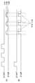
도3는 본 발명의 실시 예에 따른 비교기(130) 통과 전과 통과 후의 타이밍을 예시적으로 보여주는 도면이다. 도 3(a)에서는 비교기(130)의 통과 전에서 연속적인 송신 펄스들과 이에 대응하는 수신된 반사 펄스들이 도시된다. 수신된 반사 펄스들은 송신 펄스와 비교하여 진폭이 작아졌다.3 is a diagram illustrating a timing before and after passing the
도 3(b)에서는 비교기(130)의 통과 후에 연속적으로 선택된 기준값들(TH1, TH2, TH3)에 의해 수신 펄스들이 도시된다. 실시 예에 있어서, 기준값의 변경 시점은 이전 기준값의 폴링(falling) 시점일 수 있다. 하지만, 기준값의 변경 시점에 여기에 제한되지 않는다고 이해되어야 할 것이다. 예를 들어, 연속적으로 송신 펄스를 발생시키는 시간을 고려하여 연속적으로 기준값(TH1, TH2, TH3)이 변경될 수도 있다.In FIG. 3B, received pulses are shown by successively selected reference values TH1, TH2, TH3 after the pass of the
도 4는 본 발명의 실시 예에 따른 디지털 신호 처리기(170)에서 검출신호의 피크 시간을 계산하는 과정을 보여주는 도면이다. 도 4를 참조하면, 비교기(130)로부터 출력된 신호, 즉, 수신 펄스에 대하여 2차 함수(y = at2 + bt + c)가 완성되고, 이러한 2차 함수식을 이용하여 입력 신호에 대한 최대값(peak) 지점은, y' = 2at +b (2차 함수의 미분값)을 이용하여 시간 값(tpeak= -b/2a)이 계산될 수 있다.4 is a diagram illustrating a process of calculating a peak time of a detection signal in the
입력 신호에 대한 2차 함수에 대한 수학식은 다음과 같다.Equation for the quadratic function for the input signal is as follows.

여기서 V0, V1, V2는 기준값(도3에 도시된, TH1, TH2, TH3)이다. 따라서, 피크 시간(tpeak)은 아래의 수학식으로 표현될 수 있다.Where V0, V1, V2 are reference values (TH1, TH2, TH3, shown in FIG. 3). Therefore, the peak time tpeak may be expressed by the following equation.

본 발명의 실시 예에 따른 거리 검출 센서(100)는 신호 진폭의 감소에 대한 거리 오차를 감소시키고, TDC 구현시 상승 엣지만 검출함으로써 회로의 크기 감소시키고, 3개 이상의 펄스를 이용하여 기준값 변화시키고, 변경된 기준값 마다 시간 정보를 저장하고 이를 통해 2차 함수를 완성할 수 있다.The
도 5는 본 발명의 실시 예에 따른 거리 검출 센서(100)의 동작 방법을 예시적으로 보여주는 도면이다. 도 1 내지 도 5를 참조하면, 거리 검출 센서(100)는 다음과 같이 동작할 수 있다.5 is a diagram illustrating a method of operating the
연속적인 송신 펄스들이 타겟으로 전송될 수 있다(S110). 타겟으로부터 반사된 펄스들, 즉 검출신호들이 거리 검출 센서(100)의 내부의 감광 소자에 의해 수신될 수 있다. 수신된 검출신호들의 각각에 대응하는 기준값이 기준값 선택기(140)에서 변경될 수 있다(S120). 비교기(130)는 감광 소자에 의해 수신된 검출신호와 기준값 선택기(140)에 의해 변경된 기준값을 비교함으로써 TOF 시간에 대응하는 디지털 값이 출력될 수 있다(S130). 디지털 신호 처리기(170)는 변경된 기준값들에 의해 수신된 TOF 디지털 값들로부터 검출신호에 대한 TOF 피크 시간을 계산할 수 있다(S140). 디지털 신호 처리기(170)는 TOF 피크 시간 및 온도를 이용하여 타겟까지의 거리를 계산/보정할 수 있다(S150). Successive transmission pulses may be transmitted to the target (S110). Pulses reflected from the target, that is, detection signals, may be received by the photosensitive element inside the
본 발명에 따른 단계들 및/또는 동작들은 기술분야의 통상의 기술자에 의해 이해될 수 있는 것과 같이, 다른 순서로, 또는 병렬적으로, 또는 다른 에포크(epoch) 등을 위해 다른 실시 예들에서 동시에 일어날 수 있다.The steps and / or actions according to the invention may occur simultaneously in different embodiments in different order, in parallel, or for other epochs, etc., as would be understood by one of ordinary skill in the art. Can be.
실시 예에 따라서는, 단계들 및/또는 동작들의 일부 또는 전부는 하나 이상의 비-일시적 컴퓨터-판독가능 매체에 저장된 명령, 프로그램, 상호작용 데이터 구조(interactive data structure), 클라이언트 및/또는 서버를 구동하는 하나 이상의 프로세서들을 사용하여 적어도 일부가 구현되거나 또는 수행될 수 있다. 하나 이상의 비-일시적 컴퓨터-판독가능 매체는 예시적으로 소프트웨어, 펌웨어, 하드웨어, 및/또는 그것들의 어떠한 조합일 수 있다. 또한, 본 명세서에서 논의된 "모듈"의 기능은 소프트웨어, 펌웨어, 하드웨어, 및/또는 그것들의 어떠한 조합으로 구현될 수 있다.In some embodiments, some or all of the steps and / or actions may be directed to instructions, programs, interactive data structures, clients, and / or servers stored on one or more non-transitory computer-readable media. At least some may be implemented or performed using one or more processors. One or more non-transitory computer-readable media may be illustratively software, firmware, hardware, and / or any combination thereof. In addition, the functionality of the "module" discussed herein may be implemented in software, firmware, hardware, and / or any combination thereof.
본 발명의 실시 예들의 하나 이상의 동작들/단계들/모듈들을 구현/수행하기 위한 하나 이상의 비-일시적 컴퓨터-판독가능 매체 및/또는 수단들은 ASICs(application-specific integrated circuits), 표준 집적 회로들, 마이크로 컨트롤러를 포함하는, 적절한 명령들을 수행하는 컨트롤러, 및/또는 임베디드 컨트롤러, FPGAs(field-programmable gate arrays), CPLDs(complex programmable logic devices), 및 그와 같은 것들을 포함할 수 있지만, 여기에 한정되지는 않는다.One or more non-transitory computer-readable media and / or means for implementing / performing one or more operations / steps / modules of embodiments of the present invention may be used in application-specific integrated circuits (ASICs), standard integrated circuits, A controller that performs appropriate instructions, including a microcontroller, and / or an embedded controller, field-programmable gate arrays (FPGAs), complex programmable logic devices (CPLDs), and the like. Does not.
본 발명의 실시 예에 따른 거리 검출 센서(100)는 복수의 송신 펄스들을 송신하고, 복수의 송신 펄스들에 대응하는 수신 펄스들을 수신할 때 기준값을 서로 다르게 함으로써, 시간 변이를 보상할 수 있다. 한편, 본 발명의 실시 예에 따른 거리 검출 센서(100)는 차량용 LIDAR(light detection and ranging) 시스템에 적용 가능하다.The
한편, 상술 된 본 발명의 내용은 발명을 실시하기 위한 구체적인 실시 예들에 불과하다. 본 발명은 구체적이고 실제로 이용할 수 있는 수단 자체뿐 아니라, 장차 기술로 활용할 수 있는 추상적이고 개념적인 아이디어인 기술적 사상을 포함할 것이다.On the other hand, the content of the present invention described above is only specific embodiments for carrying out the invention. The invention will include not only specific and practically available means per se, but also technical ideas as abstract and conceptual ideas that may be utilized in future technology.
100: 거리 검출 센서
110: 전류 전압 변환기
120: 증폭기
130: 비교기
140: 기준값 선택기
150: 타임 디지털 변환기
160: 온도 센서
170: 디지털 신호 처리기100: distance detection sensor
110: current voltage converter
120: amplifier
130: comparator
140: reference selector
150: time digital converter
160: temperature sensor
170: digital signal processor
Claims (14)
Translated fromKorean상기 변환된 전압을 증폭하는 증폭기;
상기 증폭기의 출력값과 기준값을 비교함으로써 수신 펄스를 발생하는 비교기;
복수의 기준값들 중에서 어느 하나를 상기 기준값으로 선택하는 기준값 선택기; 및
상기 비교기로부터 출력된 수신 펄스에 응답하여 TOF(time-of-flight) 시간을 계산하는 시간 디지털 변환기를 포함하고,
상기 기준값 선택기는 연속적인 수신 펄스들의 각각에 대응하는 서로 다른 기준값들을 연속적으로 변경하되, 이전 수신 펄스의 폴링 시점에서 기준값을 변경하는 거리 검출 센서.A current voltage converter for converting a current corresponding to the detection signal reflected from the target into a voltage;
An amplifier for amplifying the converted voltage;
A comparator for generating a reception pulse by comparing the output value of the amplifier with a reference value;
A reference value selector for selecting any one of a plurality of reference values as the reference value; And
A time digital converter for calculating a time-of-flight time in response to a received pulse output from the comparator,
And the reference value selector continuously changes different reference values corresponding to each of the consecutive received pulses, and changes the reference value at the time of polling the previous received pulse.
상기 검출신호를 발생하는 감광 소자를 더 포함하는 거리 검출 센서.The method of claim 1,
And a photosensitive element for generating the detection signal.
상기 전류 전압 변환기는 트랜스임피던스 증폭기(trans impedance amplifier)를 포함하는 거리 검출 센서.The method of claim 1,
And the current voltage converter comprises a trans impedance amplifier.
상기 전류 전압 변환기의 입력단과 출력단 사이에 병렬 연결된 캐패시터 및 저항을 더 포함하는 거리 검출 센서.The method of claim 1,
And a capacitor and a resistor connected in parallel between an input terminal and an output terminal of the current voltage converter.
상기 시간 디지털 변환기는 송신 펄스와 수신 펄스 사이를 카운팅하는 카운터를 포함하는 거리 검출 센서.The method of claim 1,
And the time digital converter comprises a counter for counting between transmit and receive pulses.
상기 카운터는 상기 송신 펄스의 라이징 시점부터 상기 수신 펄스의 라이징 시점까지를 카운팅하는 거리 검출 센서.The method of claim 5,
And the counter counts the rising time of the transmitting pulse to the rising time of the receiving pulse.
상기 연속적인 수신 펄스들에 대응하는 연속적인 송신 펄스들이 상기 타겟으로 전송되고,
상기 연속적인 송신 펄스들은 3개 이상인 거리 검출 센서.The method of claim 1,
Successive transmit pulses corresponding to the successive receive pulses are transmitted to the target,
And the consecutive transmission pulses are three or more.
상기 연속적인 송신 펄스들의 각각에 대응하는 TOF 시간들을 계산 및 저장하는 디지털 신호 처리기를 더 포함하는 거리 검출 센서.The method of claim 1,
And a digital signal processor for calculating and storing TOF times corresponding to each of said successive transmit pulses.
상기 디지털 신호 처리기는, 상기 TOF 시간들로부터 피크 시간을 계산하고, 상기 피크 시간을 이용하여 타겟까지의 거리를 계산하는 거리 검출 센서.The method of claim 9,
And the digital signal processor calculates a peak time from the TOF times and calculates a distance to a target using the peak time.
온도를 측정하는 온도 센서를 더 포함하고,
상기 디지털 신호 처리기는 상기 온도를 이용하여 상기 거리를 보상하는 거리 검출 센서.The method of claim 9,
Further comprising a temperature sensor for measuring the temperature,
And the digital signal processor compensates for the distance using the temperature.
연속적인 송신 펄스들을 타겟으로 전송하는 단계;
상기 송신 펄스들의 각각에 대응하는 기준값을 변경하는 단계;
상기 변경된 기준값에 따라 상기 송신 펄스들의 각각에 대응하는 신호를 연속적으로 수신하는 단계;
상기 송신 펄스들의 각각에 대응하는 수신된 수신 펄스들로부터 TOF(time-of-flight) 피크 시간을 계산하는 단계; 및
상기 TOF 피크 시간으로부터 상기 타겟까지의 거리를 계산하는 단계를 포함하고,
상기 기준값을 변경하는 단계는, 이전 수신 펄스의 폴링 시점에서 기준값을 변경하는 것을 특징으로 하는 방법.In the operation method of the distance detection sensor:
Sending successive transmit pulses to a target;
Changing a reference value corresponding to each of the transmit pulses;
Continuously receiving a signal corresponding to each of the transmission pulses according to the changed reference value;
Calculating a time-of-flight peak time from received receive pulses corresponding to each of the transmit pulses; And
Calculating a distance from the TOF peak time to the target,
The changing of the reference value may include changing a reference value at a polling time point of a previous received pulse.
상기 송신 펄스들의 각각에 대응하는 검출신호들을 감광 소자로부터 수신하는 단계;
상기 수신된 검출신호들의 각각에 대응하는 전류를 전압으로 변환하는 단계; 및
상기 변환된 전압들을 증폭시키는 단계를 더 포함하는 방법.The method of claim 12,
Receiving detection signals corresponding to each of the transmission pulses from a photosensitive device;
Converting a current corresponding to each of the received detection signals into a voltage; And
Amplifying the converted voltages.
온도를 측정하는 단계; 및
상기 측정된 온도에 따라 상기 거리를 보상하는 단계를 더 포함하는 방법.The method of claim 12,
Measuring the temperature; And
Compensating for the distance according to the measured temperature.
Priority Applications (4)
| Application Number | Priority Date | Filing Date | Title |
|---|---|---|---|
| KR1020170127671AKR102019382B1 (en) | 2017-09-29 | 2017-09-29 | Distance detection sensor and operating method thereof |
| US16/033,737US11255968B2 (en) | 2017-09-29 | 2018-07-12 | Distance detection sensor and operating method thereof |
| DE102018117259.1ADE102018117259B4 (en) | 2017-09-29 | 2018-07-17 | DISTANCE DETECTION SENSOR AND METHOD FOR OPERATING SUCH A SENSOR |
| CN201810833703.0ACN109581401B (en) | 2017-09-29 | 2018-07-26 | Distance detection sensor and working method thereof |
Applications Claiming Priority (1)
| Application Number | Priority Date | Filing Date | Title |
|---|---|---|---|
| KR1020170127671AKR102019382B1 (en) | 2017-09-29 | 2017-09-29 | Distance detection sensor and operating method thereof |
Publications (2)
| Publication Number | Publication Date |
|---|---|
| KR20190037884A KR20190037884A (en) | 2019-04-08 |
| KR102019382B1true KR102019382B1 (en) | 2019-09-06 |
Family
ID=65728224
Family Applications (1)
| Application Number | Title | Priority Date | Filing Date |
|---|---|---|---|
| KR1020170127671AActiveKR102019382B1 (en) | 2017-09-29 | 2017-09-29 | Distance detection sensor and operating method thereof |
Country Status (4)
| Country | Link |
|---|---|
| US (1) | US11255968B2 (en) |
| KR (1) | KR102019382B1 (en) |
| CN (1) | CN109581401B (en) |
| DE (1) | DE102018117259B4 (en) |
Families Citing this family (7)
| Publication number | Priority date | Publication date | Assignee | Title |
|---|---|---|---|---|
| DE102019207741B4 (en) | 2019-05-27 | 2025-10-09 | Infineon Technologies Ag | A LIDAR system, a method for a LIDAR system, and a receiver for a LIDAR system having first and second conversion elements |
| KR102242503B1 (en)* | 2020-01-17 | 2021-04-19 | 한국항공대학교산학협력단 | Comparator with high precision offset calibration and lidar system including the same |
| KR102575734B1 (en)* | 2021-02-25 | 2023-09-08 | 현대자동차주식회사 | Apparatus for estimating level of signal output from photodetector and method thereof |
| KR102610763B1 (en)* | 2021-02-26 | 2023-12-07 | 현대자동차주식회사 | Apparatus for reducing noise of lidar and method thereof |
| CN115113224B (en)* | 2022-07-06 | 2025-08-29 | 杭州瑞盟科技股份有限公司 | Telescope rangefinder and distance measurement method based on telescope rangefinder |
| CN118519125B (en)* | 2024-07-19 | 2024-12-03 | 惟太科技(苏州)有限公司 | Time-of-flight photoelectric receiving system and photoelectric receiving signal processing method |
| CN118971847A (en)* | 2024-10-16 | 2024-11-15 | 杭州宇称电子技术有限公司 | Multi-threshold comparison TDC integrated circuit, control method and laser radar thereof |
Citations (3)
| Publication number | Priority date | Publication date | Assignee | Title |
|---|---|---|---|---|
| JP2000346941A (en)* | 1999-06-08 | 2000-12-15 | Mitsubishi Electric Corp | Distance measuring device |
| JP2013096905A (en)* | 2011-11-02 | 2013-05-20 | Denso Corp | Distance measuring apparatus |
| JP2017062169A (en)* | 2015-09-25 | 2017-03-30 | 株式会社リコー | CIRCUIT DEVICE, LIGHT DETECTOR, OBJECT DETECTION DEVICE, SENSING DEVICE, MOBILE DEVICE, LIGHT DETECTION METHOD, AND OBJECT DETECTION METHOD |
Family Cites Families (28)
| Publication number | Priority date | Publication date | Assignee | Title |
|---|---|---|---|---|
| JPS62231165A (en)* | 1986-03-31 | 1987-10-09 | Shimadzu Corp | Detecting device for peak position of measurement output |
| JP3337868B2 (en)* | 1995-05-26 | 2002-10-28 | セイコープレシジョン株式会社 | Camera ranging device |
| US5696657A (en)* | 1995-06-02 | 1997-12-09 | Hughes Electronics | Temperature compensated APD detector bias and transimpedance amplifier circuitry for laser range finders |
| US5691808A (en)* | 1995-07-31 | 1997-11-25 | Hughes Electronics | Laser range finder receiver |
| KR19980074950A (en)* | 1997-03-27 | 1998-11-05 | 김영환 | Distance measuring device and control method using temperature parameter of ultrasonic sensor |
| EP1382979B1 (en)* | 2001-04-25 | 2008-03-05 | Nikon Corporation | Range finder, range finding method, and photoelectric transducing circuit |
| WO2003089950A2 (en)* | 2002-04-15 | 2003-10-30 | Toolz, Ltd. | Distance measurement device |
| JP4898176B2 (en)* | 2005-09-26 | 2012-03-14 | 株式会社トプコン | Surveying device and surveying method |
| KR101256678B1 (en)* | 2006-12-22 | 2013-04-19 | 두산디에스티주식회사 | A Protecting Unit of a LASER Road Measuring Unit and Method Thereof |
| CN101216562A (en)* | 2007-01-05 | 2008-07-09 | 薛志强 | Laser distance measuring system |
| CN102597693B (en)* | 2009-11-13 | 2015-04-01 | 富士胶片株式会社 | Distance measuring device, distance measuring method, distance measuring program, distance measuring system, and image capturing device |
| KR101153539B1 (en)* | 2009-12-18 | 2012-06-11 | 한국과학기술원 | Position measuring appratus for vehicle and position measuring method using there of |
| US8619239B2 (en)* | 2011-01-28 | 2013-12-31 | Analog Modules Inc. | Accuracy of a laser rangefinder receiver |
| JP2014102072A (en) | 2011-03-08 | 2014-06-05 | National Univ Corp Shizuoka Univ | Signal processing circuit for distance measurement and distance measurement device |
| KR20130031706A (en)* | 2011-09-21 | 2013-03-29 | 현대모비스 주식회사 | Control method of communication module using proximity sensor and multimedia system using the same |
| CN102621540A (en)* | 2012-04-18 | 2012-08-01 | 北京理工大学 | Range finding method of pulsed laser rangefinder |
| FR2998051B1 (en)* | 2012-11-09 | 2014-12-26 | Thales Sa | RECEIVER OF IMPULSIVE LIGHT SIGNAL WITH HIGH DYNAMIC |
| KR101524453B1 (en)* | 2013-08-28 | 2015-06-01 | 청주대학교 산학협력단 | A Scintillation Detector with Temperature Compensation Funtion and Control Method thereof |
| EP3088914B1 (en)* | 2013-12-27 | 2020-05-06 | Ricoh Company, Ltd. | Distance measuring apparatus, electronic apparatus, distance measuring method, and distance measuring program |
| KR102144543B1 (en) | 2014-05-08 | 2020-08-18 | 주식회사 히타치엘지 데이터 스토리지 코리아 | Method for detecting signal in TOF camera |
| KR101655289B1 (en)* | 2014-12-12 | 2016-09-08 | 현대오트론 주식회사 | Apparatus and method for compensating output signal |
| US11131756B2 (en) | 2015-09-29 | 2021-09-28 | Qualcomm Incorporated | LIDAR system with reflected signal strength measurement |
| US10234549B2 (en)* | 2016-03-08 | 2019-03-19 | Semiconductor Components Industries, Llc | Circuit for acoustic distance time of flight compensation |
| KR20170127671A (en) | 2016-05-12 | 2017-11-22 | 한상호 | A method of preparing functional fermented soybean powder comprising beet extract using ultra-high pressure |
| CN106019300A (en)* | 2016-08-05 | 2016-10-12 | 上海思岚科技有限公司 | Laser ranging device and laser ranging method thereof |
| US10585174B2 (en)* | 2017-03-10 | 2020-03-10 | Sensl Technologies Ltd. | LiDAR readout circuit |
| US11022688B2 (en)* | 2017-03-31 | 2021-06-01 | Luminar, Llc | Multi-eye lidar system |
| US11428790B2 (en)* | 2017-06-05 | 2022-08-30 | Texas Instruments Incorporated | Narrowband TIA and signaling for optical distance measurement systems |
- 2017
- 2017-09-29KRKR1020170127671Apatent/KR102019382B1/enactiveActive
- 2018
- 2018-07-12USUS16/033,737patent/US11255968B2/enactiveActive
- 2018-07-17DEDE102018117259.1Apatent/DE102018117259B4/enactiveActive
- 2018-07-26CNCN201810833703.0Apatent/CN109581401B/enactiveActive
Patent Citations (3)
| Publication number | Priority date | Publication date | Assignee | Title |
|---|---|---|---|---|
| JP2000346941A (en)* | 1999-06-08 | 2000-12-15 | Mitsubishi Electric Corp | Distance measuring device |
| JP2013096905A (en)* | 2011-11-02 | 2013-05-20 | Denso Corp | Distance measuring apparatus |
| JP2017062169A (en)* | 2015-09-25 | 2017-03-30 | 株式会社リコー | CIRCUIT DEVICE, LIGHT DETECTOR, OBJECT DETECTION DEVICE, SENSING DEVICE, MOBILE DEVICE, LIGHT DETECTION METHOD, AND OBJECT DETECTION METHOD |
Also Published As
| Publication number | Publication date |
|---|---|
| CN109581401B (en) | 2024-01-16 |
| KR20190037884A (en) | 2019-04-08 |
| US11255968B2 (en) | 2022-02-22 |
| DE102018117259A1 (en) | 2019-04-04 |
| US20190101648A1 (en) | 2019-04-04 |
| DE102018117259B4 (en) | 2025-07-17 |
| CN109581401A (en) | 2019-04-05 |
Similar Documents
| Publication | Publication Date | Title |
|---|---|---|
| KR102019382B1 (en) | Distance detection sensor and operating method thereof | |
| US11125863B2 (en) | Correction device, correction method, and distance measuring device | |
| CN101490579B (en) | Optical distance measuring method and corresponding optical distance measurement device | |
| KR102030457B1 (en) | An Apparatus And Method For Compensating Time Variation For Distance Detection Sensor | |
| US8625081B2 (en) | Method and device for measuring distance | |
| US10852401B2 (en) | Distance measurement apparatus and distance measurement method | |
| US11415684B2 (en) | Monitoring device of a LIDAR system | |
| CN205992055U (en) | A kind of laser ranging system | |
| WO2020139381A1 (en) | System and methods for ranging operations using multiple signals | |
| KR102610763B1 (en) | Apparatus for reducing noise of lidar and method thereof | |
| WO2012121337A1 (en) | Distance measurement signal processing circuit and distance measuring apparatus | |
| CN207601308U (en) | A kind of laser ranging system | |
| CN112162291B (en) | Laser radar signal processing circuit and laser radar | |
| CN104777471A (en) | Pulse laser short-range dynamic gain control circuit | |
| JPWO2019050024A1 (en) | Distance measurement method and distance measurement device | |
| US20230204735A1 (en) | Detection apparatus and method | |
| US20230184940A1 (en) | Measurement unit, and measurement apparatus and method | |
| JP6571502B2 (en) | UWB measurement system | |
| JP6399971B2 (en) | Laser radar equipment | |
| CN213338033U (en) | Laser radar signal processing circuit and laser radar | |
| CN110850427A (en) | Amplifying circuit for laser radar, laser radar and control method | |
| US20220206115A1 (en) | Detection and ranging operation of close proximity object | |
| KR102308786B1 (en) | Vehicle lidar system and signal processing method thereof | |
| CN110208775B (en) | A lidar receiving chip, lidar chip and lidar system | |
| CN112558095A (en) | Laser ranging method, device and system |
Legal Events
| Date | Code | Title | Description |
|---|---|---|---|
| A201 | Request for examination | ||
| PA0109 | Patent application | Patent event code:PA01091R01D Comment text:Patent Application Patent event date:20170929 | |
| PA0201 | Request for examination | ||
| E902 | Notification of reason for refusal | ||
| PE0902 | Notice of grounds for rejection | Comment text:Notification of reason for refusal Patent event date:20190306 Patent event code:PE09021S01D | |
| PG1501 | Laying open of application | ||
| E701 | Decision to grant or registration of patent right | ||
| PE0701 | Decision of registration | Patent event code:PE07011S01D Comment text:Decision to Grant Registration Patent event date:20190820 | |
| GRNT | Written decision to grant | ||
| PR0701 | Registration of establishment | Comment text:Registration of Establishment Patent event date:20190902 Patent event code:PR07011E01D | |
| PR1002 | Payment of registration fee | Payment date:20190902 End annual number:3 Start annual number:1 | |
| PG1601 | Publication of registration | ||
| PR1001 | Payment of annual fee | Payment date:20220725 Start annual number:4 End annual number:4 | |
| PR1001 | Payment of annual fee | Payment date:20240826 Start annual number:6 End annual number:6 |