KR102015788B1 - Test device - Google Patents
Test deviceDownload PDFInfo
- Publication number
- KR102015788B1 KR102015788B1KR1020170162775AKR20170162775AKR102015788B1KR 102015788 B1KR102015788 B1KR 102015788B1KR 1020170162775 AKR1020170162775 AKR 1020170162775AKR 20170162775 AKR20170162775 AKR 20170162775AKR 102015788 B1KR102015788 B1KR 102015788B1
- Authority
- KR
- South Korea
- Prior art keywords
- cable
- probe
- signal
- contact
- hole
- Prior art date
- Legal status (The legal status is an assumption and is not a legal conclusion. Google has not performed a legal analysis and makes no representation as to the accuracy of the status listed.)
- Active
Links
Images


Classifications
- G—PHYSICS
- G01—MEASURING; TESTING
- G01R—MEASURING ELECTRIC VARIABLES; MEASURING MAGNETIC VARIABLES
- G01R1/00—Details of instruments or arrangements of the types included in groups G01R5/00 - G01R13/00 and G01R31/00
- G01R1/02—General constructional details
- G01R1/18—Screening arrangements against electric or magnetic fields, e.g. against earth's field
- G—PHYSICS
- G01—MEASURING; TESTING
- G01R—MEASURING ELECTRIC VARIABLES; MEASURING MAGNETIC VARIABLES
- G01R1/00—Details of instruments or arrangements of the types included in groups G01R5/00 - G01R13/00 and G01R31/00
- G01R1/02—General constructional details
- G01R1/04—Housings; Supporting members; Arrangements of terminals
- G01R1/0408—Test fixtures or contact fields; Connectors or connecting adaptors; Test clips; Test sockets
- G01R1/0433—Sockets for IC's or transistors
- G01R1/0441—Details
- G01R1/045—Sockets or component fixtures for RF or HF testing
- G—PHYSICS
- G01—MEASURING; TESTING
- G01R—MEASURING ELECTRIC VARIABLES; MEASURING MAGNETIC VARIABLES
- G01R1/00—Details of instruments or arrangements of the types included in groups G01R5/00 - G01R13/00 and G01R31/00
- G01R1/02—General constructional details
- G01R1/06—Measuring leads; Measuring probes
- G01R1/067—Measuring probes
- G01R1/06711—Probe needles; Cantilever beams; "Bump" contacts; Replaceable probe pins
- G—PHYSICS
- G01—MEASURING; TESTING
- G01R—MEASURING ELECTRIC VARIABLES; MEASURING MAGNETIC VARIABLES
- G01R1/00—Details of instruments or arrangements of the types included in groups G01R5/00 - G01R13/00 and G01R31/00
- G01R1/02—General constructional details
- G01R1/06—Measuring leads; Measuring probes
- G01R1/067—Measuring probes
- G01R1/06772—High frequency probes
- G—PHYSICS
- G01—MEASURING; TESTING
- G01R—MEASURING ELECTRIC VARIABLES; MEASURING MAGNETIC VARIABLES
- G01R31/00—Arrangements for testing electric properties; Arrangements for locating electric faults; Arrangements for electrical testing characterised by what is being tested not provided for elsewhere
- G01R31/26—Testing of individual semiconductor devices
- G—PHYSICS
- G01—MEASURING; TESTING
- G01R—MEASURING ELECTRIC VARIABLES; MEASURING MAGNETIC VARIABLES
- G01R31/00—Arrangements for testing electric properties; Arrangements for locating electric faults; Arrangements for electrical testing characterised by what is being tested not provided for elsewhere
- G01R31/28—Testing of electronic circuits, e.g. by signal tracer
- G01R31/2851—Testing of integrated circuits [IC]
- G01R31/2886—Features relating to contacting the IC under test, e.g. probe heads; chucks
- G—PHYSICS
- G01—MEASURING; TESTING
- G01R—MEASURING ELECTRIC VARIABLES; MEASURING MAGNETIC VARIABLES
- G01R31/00—Arrangements for testing electric properties; Arrangements for locating electric faults; Arrangements for electrical testing characterised by what is being tested not provided for elsewhere
- G01R31/50—Testing of electric apparatus, lines, cables or components for short-circuits, continuity, leakage current or incorrect line connections
- G01R31/66—Testing of connections, e.g. of plugs or non-disconnectable joints
- G01R31/70—Testing of connections between components and printed circuit boards
Landscapes
- Physics & Mathematics (AREA)
- General Physics & Mathematics (AREA)
- Engineering & Computer Science (AREA)
- Computer Hardware Design (AREA)
- Microelectronics & Electronic Packaging (AREA)
- General Engineering & Computer Science (AREA)
- Measuring Leads Or Probes (AREA)
- Testing Of Individual Semiconductor Devices (AREA)
Abstract
Translated fromKoreanDescription
Translated fromKorean본 발명은 검사장치, 더욱 상세하게는 인접하는 신호라인과의 노이즈를 효과적으로 차단하고 신호의 전달 특성이 우수한 고속 및 고주파 검사용 검사장치에 관한 것이다.The present invention relates to an inspection apparatus, and more particularly, to an inspection apparatus for high speed and high frequency inspection, which effectively blocks noise with adjacent signal lines and has excellent signal transmission characteristics.
반도체와 같은 검사대상 디바이스의 전기적 특성을 검사하기 위해 검사장치는 검사프로브를 지지하는 프로브 소켓 및 검사프로브에 접촉하여 검사신호를 인가하는 검사회로기판이 사용되고 있다. 고주파수, 고속용 반도체는 그 피치가 작아지고 허용 전류가 늘어나고 있는 추세로서, 프로브 소켓의 신호용 프로브들 간의 노이즈 차폐가 매우 중요한 인자가 되고 있다. 즉, 테스트 속도 및 주파수가 점점 높아짐에 따라 검사회로기판의 기구적인 길이, 임피던스 매칭 등이 중요한 요소가 되고 있다.In order to inspect the electrical characteristics of a device under test such as a semiconductor, a test apparatus that uses a probe socket for supporting a test probe and a test circuit board for applying a test signal to the test probe is used. High frequency and high speed semiconductors have become smaller in pitch and allowable current increases, and noise shielding between signal probes of a probe socket has become a very important factor. In other words, as test speed and frequency increase, mechanical length, impedance matching, and the like of the test circuit board become important factors.
종래의 검사장치는 신호용 프로브를 지지하는 프로브소켓 및 프로브소켓의 하측에 배치되어 검사신호를 제공하는 검사회로기판을 포함한다. 프로브소켓은 도전성 황동블록에 신호용 프로브가 비접촉 상태로 삽입되어 검사가 수행된다. 또한, 검사회로기판은 절연성 유전체 기판에 형성된 검사신호를 전달하는 도전컬럼 및 신호패드를 포함한다. 고주파수, 고속용 반도체와 같이 고격리성(High Isolation)이 요구되는 대상을 검사할 경우 프로브소켓의 인접한 신호용 프로브들 사이를 도전성 접지체로 차폐하는 기술이 적용되고 있다. 그러나 더욱 신뢰성 있는 검사를 위해서는 검사회로기판의 도전컬럼들 사이 및 신호패드들 사이에서 발생하는 노이즈에 의한 격리(Isolation) 손실을 최소한으로 관리할 필요가 있다. 또한, 검사회로기판은 일정 길이의 선로를 갖기 때문에, 선로 길이에 따른 신호손실을 초래하여 신호전달특성이 나빠진다.The conventional inspection apparatus includes a probe socket for supporting a signal probe and an inspection circuit board disposed under the probe socket to provide an inspection signal. The probe socket is inspected by inserting a non-contact signal probe into the conductive brass block. In addition, the test circuit board includes a conductive column and a signal pad for transmitting a test signal formed on the insulating dielectric substrate. When inspecting an object requiring high isolation such as high frequency and high speed semiconductor, a technique of shielding between adjacent signal probes of a probe socket with a conductive grounding body has been applied. However, for more reliable inspection, it is necessary to minimize the loss of isolation due to noise generated between the conductive columns of the test circuit board and the signal pads. In addition, since the inspection circuit board has a line having a certain length, the signal transmission characteristic is degraded due to signal loss along the line length.
본 발명의 목적은 상술한 종래의 문제를 해결하기 위한 것으로, 인접하는 신호라인들 간의 노이즈를 효과적으로 차단하고, 검사신호의 전달특성이 우수한 고주파수, 고속용 반도체를 검사하는 검사장치를 제공함에 있다.DISCLOSURE OF THE INVENTION An object of the present invention is to solve the above-mentioned conventional problems, and to provide an inspection apparatus for inspecting high frequency and high speed semiconductors, which effectively blocks noise between adjacent signal lines and has excellent transmission characteristics of inspection signals.
상술한 과제를 해결하기 위한 검사장치가 제공된다. 검사장치는 프로브공을 가진 도전블록과, 상기 프로브공의 내벽에 비접촉 상태로 지지되며, 상기 피검사체의 피검사접점과 검사신호를 인가하는 신호접점 사이를 신축적으로 연결하는 적어도 하나의 신호프로브와, 상기 신호프로브에 접촉하는 신호접점을 형성하는 심선을 가진 동축케이블을 포함하는 것을 특징으로 한다. 본 발명의 검사장치는 케이블지지기판에서 발생하는 신호프로브들 간의 노이즈를 확실하게 차폐하고 검사신호의 전달특성을 향상시킬 수 있다.An inspection apparatus for solving the above problems is provided. At least one signal probe which is connected between the conductive block having the probe hole and the inner wall of the probe hole in a non-contact state, and at least one signal probe that elastically connects the contact point to be inspected and the signal contact to which the test signal is applied. And, characterized in that it comprises a coaxial cable having a core wire forming a signal contact in contact with the signal probe. The inspection apparatus of the present invention can reliably shield the noise between signal probes generated from the cable support substrate and improve the transmission characteristic of the inspection signal.
상기 동축케이블을 수용하는 케이블수용공을 포함하고, 상기 프로브공과 상기 케이블수용공이 대응하도록 상기 도전블록에 결합되는 케이블지지블록을 가진 케이블지지부를 더 포함함으로써 동축케이블을 견고하게 지지할 수 있다.And a cable supporting part including a cable receiving hole accommodating the coaxial cable and having a cable support block coupled to the conductive block so that the probe hole and the cable receiving hole correspond to each other.
상기 케이블지지블록은 상기 동축케이블을 고정하는 케이블고정함몰부를 포함함으로써 동축케이블의 유동을 방지할 수 있다.The cable support block may include a cable fixing recess for fixing the coaxial cable to prevent the flow of the coaxial cable.
상기 케이블지지부는 상기 케이블지지블록으로부터 일체로 확장하는 확장판부를 포함함으로써 동축케이블들 간의 간섭을 방지할 수 있다.The cable support part may include an extension plate part integrally extending from the cable support block to prevent interference between coaxial cables.
상기 케이블지지부는 상기 케이블지지블록이 통과하는 관통공을 가진 케이블지지기판을 포함함으로써 케이블지지블록을 안정적으로 도전블록에 결합할 수 있다.The cable support part may include a cable support substrate having a through hole through which the cable support block passes, thereby stably coupling the cable support block to the conductive block.
본 발명의 검사장치는 도전블록에 지지된 신호프로브가 동축케이블의 심선에 직접 접촉함으로써 절연회로기판 측의 신호라인들 사이의 노이즈를 확실하게 차단하고 검사신호의 전달특성을 좋게 하는 것이 가능하다. 이에 의해, 본 발명의 검사장치는 고속/고주파 테스트에서의 검사 신뢰성을 향상시킬 수 있다.In the inspection apparatus of the present invention, the signal probe supported by the conductive block is in direct contact with the core wire of the coaxial cable, whereby the noise between the signal lines on the insulated circuit board side can be reliably cut off, and the transmission characteristic of the inspection signal can be improved. Thereby, the inspection apparatus of the present invention can improve inspection reliability in high speed / high frequency testing.
도 1은 본 발명의 제1실시예에 따른 검사장치의 검사소켓 분해단면도,
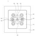
도 2는 본 발명의 제1실시예에 따른 검사장치를 나타내는 평면도,
도 3은 본 발명의 검사장치의 하부사시도,
도 4는 본 발명의 검사장치의 분해사시도,
도 5는 본 발명의 검사장치의 단면도,
도 6은 신호프로브와 동축케이블의 결합상태를 상세히 나타내는 부분확대단면도, 및.
도 7은 본 발명의 다른 실시예에 따른 검사장치를 나타내는 단면도이다.1 is an exploded cross-sectional view of an inspection socket of an inspection apparatus according to a first embodiment of the present invention;
2 is a plan view showing an inspection apparatus according to a first embodiment of the present invention;
Figure 3 is a bottom perspective view of the inspection device of the present invention,
4 is an exploded perspective view of the inspection apparatus of the present invention,
5 is a cross-sectional view of the inspection device of the present invention,
6 is a partially enlarged cross-sectional view showing in detail the coupling state of the signal probe and the coaxial cable;
7 is a cross-sectional view showing a test apparatus according to another embodiment of the present invention.
이하 도면들을 참조하여 본 발명에 따른 검사장치(1)를 상세히 설명하기로 한다.Hereinafter, the
도 1은 본 발명의 제1실시예에 따른 검사장치(1)의 검사소켓(100) 분해단면도, 도 2 내지 5는 각각 본 발명의 제1실시예에 따른 검사장치(1)의 평면도, 하부사시도, 분해사시도, 단면도 및 부분확대단면이다. 도시한 바와 같이, 검사장치(1)는 검사소켓(100), 동축케이블(200), 및 케이블지지부(300)를 포함한다.1 is an exploded cross-sectional view of an
도 1에서, 검사소켓(100)은 적어도 하나의 신호프로브공(112) 및 적어도 하나의 접지프로브공(114)을 가진 도전블록(110), 신호프로브공(112)에 비접촉 상태로 수용되는 신호프로브(120), 접지프로브공(114)에 접촉 상태로 수용되는 접지프로브(130), 신호프로브(120)의 상단을 지지하는 상부지지부재(140) 및 신호프로브(112)의 하단을 지지하는 하부지지부재(150)를 포함한다.In FIG. 1, the
도전블록(110)은 상측에 상부지지부재(140)를 수용하는 상부지지부재 수용홈(116)을 포함한다. 상부지지부재 수용홈(116)은 중앙에 돌출하는 차폐아일랜드(117)를 포함한다. 차폐아일랜드(117)는 비도전성의 상부지지부재(140)에 지지되는 신호프로브들(120) 사이의 노이즈를 차폐한다. 중앙의 신호프로브(120)는 신호프로브공(112)을 비접촉 상태로 통과하여 상부지지부재(140)에 의해 지지된다.The
도 2에서, 3개의 신호브로브들(112) 사이에는 차폐아일랜드(117)가 개재되고, 5개의 접지프로브(114)는 차폐아일랜드(117)에 접촉 지지된다. 결과적으로, 신호프로브들(120)은 접지상태의 차폐아일랜드(117)에 의해 노이즈가 차폐될 수 있다.In FIG. 2, a shielded
신호프로브(120)는 상단이 피검사체의 피검사접점(미도시)에 접촉하고 하단이 동축케이블(200)의 심선(210)에 접촉한다. 신호프로브(120)는 동축케이블(200)의 심선(210)을 통해 검사신호가 인가된다. 신호프로브(120)는 신축 가능하도록 포고핀 타입으로 구현될 수 있다. 신호프로브(120)는 배럴(미도시), 배럴 양단에 부분 삽입되는 상부 및 하부플런저(미도시), 및 배럴 내에 상하플런저 사이에 배치된 스프링(미도시)을 포함한다. 상부 및 하부플런저 중 적어도 하나는 배럴 내에서 스프링을 압축할 수 있도록 슬라이딩 이동 가능하게 삽입된다.The
접지프로브(130)는 상단이 피검사체(미도시)의 접지단자에 접촉하고, 하단이 케이블지지부(300)에 접촉한다. 접지프로브(130)는 피검사체로부터 접지신호가 인가된다. 접지프로브(130)는 신축 가능하도록 포고핀 타입으로 구현될 수 있다. 접지프로브(120)는 배럴(미도시), 배럴 양단에 부분 삽입되는 상부 및 하부플런저(미도시), 및 배럴 내에 상하플런저 사이에 배치된 스프링(미도시)을 포함한다. 상부 및 하부플런저 중 적어도 하나는 배럴 내에서 스프링을 압축할 수 있도록 슬라이딩 이동 가능하게 삽입된다. 접지프로브(130)는 도전블록(110)에 접촉 상태로 지지된다.The
상부지지부재(140)는 신호프로브(120)의 상단을 지지하기 위해 제1나사(142)에 의해 상부지지부재 수용홈(116)에 수용된 상태로 도전블록(110)에 고정된다. 신호프로브(120)는 쇼트 방지를 위해 도전블록(110)의 신호프로브공(112)에 비접촉 상태로 플로팅 삽입되며, 이를 위해 절연성의 상부지지부재(140)가 신호프로브(120)의 상단을 지지한다.The
하부지지부재(150)는 도전성 재질로서 신호프로브(120)의 하단을 지지하기 위해 하부지지부재 수용홈(118)에 수용된다. 신호프로브(120)는 쇼트 방지를 위해 도전블록(110)의 신호프로브공(112)에 비접촉 상태로 플로팅 삽입된다. 하부지지부재(150)는 신호프로브(120)의 하단을 지지하기 위해 절연성의 신호프로브 지지부재(152)를 포함한다. 결과적으로, 신호프로브(120)는 도전블록(110)과 하부지지부재(150)에는 비접촉 상태로 통과하고 양단이 상부지지부재(140)와 신호프로브 지지부재(152)에 의해 지지된다.The
신호프로브공(112)과 접지프로브공(114)은 상부지지부재(140), 도전블록(110)과 하부지지부재(150)에 연통하여 형성된다. 결과적으로 신호프로브(120) 및 접지프로브(130)는 신호프로브공(112)과 접지프로브공(114)에 각각 비접촉상태 및 접촉상태로 삽입된다. 이때, 신호프로브(120) 및 접지프로브(130)는 각각 양단이 상부지지부재(140) 및 도전블록(110)의 상면과 하면으로부터 부분 돌출된다.The
동축케이블(200)은 중앙에 신호 전달을 위한 심선(210), 노이즈 차폐를 위해 심선(210)과 이격되어 외곽을 둘러싸는 외부도체부(220), 및 심선(210)과 외부도체부(220) 사이에 채워지는 절연부(230)로 구성된다. 동축케이블(200)의 심선(210)은 신호프로브(120)에 접촉을 위해 연마 처리된다. 신호프로브(120)에 접촉하는 동축케이블(200)의 일단은 후술하는 케이블지지블록(310)에, 타단은 일단으로부터 이격된 위치의 케이블지지기판(320)에 지지된다. 동축케이블(200)는 외부로부터 검사신호를 수신하기 위한 신호커넥터(240)를 포함한다. 신호커넥터(240)는 케이블지지기판(320)에 장착된다.The
케이블지지부(300)는 동축케이블(200)을 수용하는 케이블수용공(312)을 가진 케이블지지블록(310) 및 검사소켓(100)을 장착하는 케이블지지기판(320)을 포함한다.The cable support part 300 includes a
케이블지지블록(310)은 하부지지부재(150)의 신호프로브공(112)에 상응하는 위치에 다수의 케이블수용공(312)을 포함한다. 케이블지지블록(310)은 도전성을 가진 금속으로 제작되는 것이 바람직하다. 케이블지지블록(310)은 케이블지지기판(320)의 관통공(322)에 삽입된 상태에서 도전블록(110)에 제2나사(144)로 고정결합된다. 케이블지지블록(310)은 도전블록(110)에 접촉하는 부위의 반대측에 파여진 케이블지지함몰부(314) 및 횡으로 확장되는 확장판부(316)를 포함한다. 동축케이블(200)은 케이블지지함몰부(314) 내의 케이블수용공(312)에 삽입된 상태에서 접(점)착제(315)가 케이블지지함몰부(314)에 채워 넣어져 고정된다. 확장판부(316)는 케이블지지기판(320)의 이면에 접촉하여 검사소켓(100)과 함께 케이블지지기판(320)을 지지한다. The
케이블지지기판(320)은 일면에 검사소켓(100)을 장착하고, 이면에 노이즈 차폐를 위해 동축케이블들(200)의 타단을 각각 분리시켜 부착한다. 케이블지지기판(300)은 케이블지지블록(310)이 관통하여 수용되는 관통공(322)을 포함한다.The
도 7은 본 발명의 제2실시예에 따른 검사장치(2)를 나타내는 단면도이다. 도 1 내지 6에 나타낸 실시예의 검사장치(1)와 동일한 부분은 동일부호를 부여하였고, 다른 부분만을 설명한다.7 is a cross-sectional view showing an
도시한 바와 같이, 검사장치(2)는 검사소켓(100), 동축케이블(200), 및 케이블지지부(300)를 포함한다.As shown, the
케이블지지부(300)는 제1실시예와 다르게 케이블지지기판(320)이 생략되고, 신호커넥터(240)가 케이블지지기판(320) 대신에 확장판부(316)에 고정되어 있다.Unlike the first embodiment, the cable support part 300 omits the
이상과 같이 본 발명은 한정된 예시적 실시예와 도면을 통해 설명되었으나, 본 발명은 상기의 예시적 실시예에 한정되는 것은 아니며, 본 발명이 속하는 분야에서 통상의 지식을 가진 자라면 이러한 기재로부터 다양한 수정 및 변형이 가능하다.As described above, the present invention has been described through limited exemplary embodiments and drawings, but the present invention is not limited to the exemplary embodiments described above, and those skilled in the art to which the present invention pertains can various Modifications and variations are possible.
그러므로 본 발명의 범위는 설명된 예시적 실시예에 국한되어 정해져서는 아니 되며, 후술하는 특허청구범위뿐 아니라 이 특허청구범위와 균등한 것들에 의해 정해져야 한다.Therefore, the scope of the present invention should not be limited to the exemplary embodiments described, but should be defined not only by the claims below but also by the equivalents of the claims.
1, 2: 검사장치
100: 검사소켓
110: 도전블록
120: 신호프로브
130: 접지프로브
140: 상부지지부재
150: 하부지지부재
200: 동축케이블
300: 케이블지지부
310: 케이블지지블록
320: 케이블지지기판1, 2: Inspection device
100: inspection socket
110: Challenge Block
120: signal probe
130: ground probe
140: upper support member
150: lower support member
200: coaxial cable
300: cable support
310: cable support block
320: cable support substrate
Claims (5)
Translated fromKorean프로브공을 가진 도전성블록과;
상기 프로브공의 내벽에 비접촉 상태로 지지되며, 상기 피검사체의 피검사접점과 검사신호를 인가하는 신호접점 사이를 신축적으로 연결하는 적어도 하나의 신호프로브와;
상기 도전성블록에 접촉 상태로 지지되는 적어도 하나의 접지프로브와;
상기 신호프로브에 접촉하는 신호접점을 형성하는 심선을 가진 동축케이블을 포함하며,
상기 동축케이블을 수용하는 케이블수용공을 포함하고, 상기 프로브공과 상기 케이블수용공이 대응하도록 상기 도전성블록에 결합되는 케이블지지블록을 가진 케이블지지부를 더 포함하며,
상기 도전성블록은 상부도전블록과 하부도전블록을 포함하며,
상기 상부도전블록은 상면에 상부지지부재 수용홈을 포함하며,
상기 상부지지부재 수용홈의 중앙에는 상기 접지프로브가 지지된 차폐아일랜드가 돌출되며,
상기 차폐아일랜드는 복수의 신호브로브들 사이에 개재되며,
상기 케이블지지블록은 상기 동축케이블을 고정하는 케이블고정함몰부를 포함하며,
상기 동축케이블은 상기 케이블고정함몰부에 채워진 접착제에 의해 고정되는 검사장치.In the inspection device for inspecting the electrical characteristics of the subject,
A conductive block having a probe hole;
At least one signal probe which is supported in an inner wall of the probe hole in a non-contact state and elastically connects an inspected contact of the inspected object with a signal contact for applying a test signal;
At least one ground probe supported in contact with the conductive block;
It includes a coaxial cable having a core wire forming a signal contact in contact with the signal probe,
And including a cable receiving hole for receiving the coaxial cable, and further comprising a cable support having a cable support block coupled to the conductive block so that the probe hole and the cable receiving hole,
The conductive block includes an upper conductive block and a lower conductive block,
The upper conductive block includes an upper support member receiving groove on the upper surface,
A shielding island on which the ground probe is supported protrudes from the center of the upper support member receiving groove,
The shielding island is interposed between a plurality of signal groves,
The cable support block includes a cable fixing recess for fixing the coaxial cable,
And the coaxial cable is fixed by an adhesive filled in the cable fixing recess.
상기 케이블지지부는 상기 케이블지지블록으로부터 일체로 확장하는 확장판부를 포함하는 검사장치.The method of claim 1,
And the cable support part includes an extension plate part integrally extending from the cable support block.
상기 케이블지지부는 상기 케이블지지블록이 통과하는 관통공을 가진 케이블지지기판을 포함하는 검사장치.The method of claim 4, wherein
And the cable support part includes a cable support substrate having a through hole through which the cable support block passes.
Priority Applications (9)
| Application Number | Priority Date | Filing Date | Title |
|---|---|---|---|
| KR1020170162775AKR102015788B1 (en) | 2017-11-30 | 2017-11-30 | Test device |
| EP18883317.2AEP3669196B1 (en) | 2017-11-30 | 2018-11-22 | Test device |
| PCT/KR2018/014396WO2019107830A1 (en) | 2017-11-30 | 2018-11-22 | Test device |
| CN201880069228.2ACN111279203B (en) | 2017-11-30 | 2018-11-22 | Test device |
| JP2020541331AJP7097452B2 (en) | 2017-11-30 | 2018-11-22 | Inspection equipment |
| TW107141560ATWI700500B (en) | 2017-11-30 | 2018-11-22 | Test device |
| SG11202002291TASG11202002291TA (en) | 2017-11-30 | 2018-11-22 | Test device |
| US16/850,116US11391757B2 (en) | 2017-11-30 | 2020-04-16 | Test device |
| US17/705,639US11726111B2 (en) | 2017-11-30 | 2022-03-28 | Test device |
Applications Claiming Priority (1)
| Application Number | Priority Date | Filing Date | Title |
|---|---|---|---|
| KR1020170162775AKR102015788B1 (en) | 2017-11-30 | 2017-11-30 | Test device |
Publications (2)
| Publication Number | Publication Date |
|---|---|
| KR20190063759A KR20190063759A (en) | 2019-06-10 |
| KR102015788B1true KR102015788B1 (en) | 2019-08-29 |
Family
ID=66664546
Family Applications (1)
| Application Number | Title | Priority Date | Filing Date |
|---|---|---|---|
| KR1020170162775AActiveKR102015788B1 (en) | 2017-11-30 | 2017-11-30 | Test device |
Country Status (8)
| Country | Link |
|---|---|
| US (2) | US11391757B2 (en) |
| EP (1) | EP3669196B1 (en) |
| JP (1) | JP7097452B2 (en) |
| KR (1) | KR102015788B1 (en) |
| CN (1) | CN111279203B (en) |
| SG (1) | SG11202002291TA (en) |
| TW (1) | TWI700500B (en) |
| WO (1) | WO2019107830A1 (en) |
Families Citing this family (5)
| Publication number | Priority date | Publication date | Assignee | Title |
|---|---|---|---|---|
| CN112098749B (en)* | 2019-09-05 | 2024-08-13 | 日置电机株式会社 | Measuring device |
| CN112824912B (en)* | 2019-11-20 | 2024-12-27 | 嘉联益电子(昆山)有限公司 | Transmission line test module and transmission line test method |
| TWI800098B (en)* | 2021-11-15 | 2023-04-21 | 貿聯國際股份有限公司 | Testing board |
| KR102714431B1 (en)* | 2022-02-17 | 2024-10-11 | 리노공업주식회사 | Test Device |
| KR102805950B1 (en)* | 2022-12-22 | 2025-05-13 | 리노공업주식회사 | Test socket |
Citations (2)
| Publication number | Priority date | Publication date | Assignee | Title |
|---|---|---|---|---|
| JP2001099889A (en) | 1999-09-29 | 2001-04-13 | Yokowo Co Ltd | Inspection equipment for high frequency circuit |
| JP2003270291A (en)* | 2002-03-18 | 2003-09-25 | Murata Mfg Co Ltd | Inspection device for high-frequency product |
Family Cites Families (26)
| Publication number | Priority date | Publication date | Assignee | Title |
|---|---|---|---|---|
| JPH0652748B2 (en)* | 1987-05-12 | 1994-07-06 | 東京エレクトロン株式会社 | Probe card |
| JP2539453B2 (en)* | 1987-09-11 | 1996-10-02 | 株式会社日立製作所 | Semiconductor element inspection equipment |
| JP3192270B2 (en)* | 1993-05-10 | 2001-07-23 | 株式会社日立製作所 | Electrode connection device |
| US5426372A (en)* | 1993-07-30 | 1995-06-20 | Genrad, Inc. | Probe for capacitive open-circuit tests |
| US5561377A (en)* | 1995-04-14 | 1996-10-01 | Cascade Microtech, Inc. | System for evaluating probing networks |
| US6420888B1 (en) | 2000-09-29 | 2002-07-16 | Schlumberger Technologies, Inc. | Test system and associated interface module |
| JP2003207539A (en) | 2002-01-10 | 2003-07-25 | Murata Mfg Co Ltd | Inspection device |
| JP4251855B2 (en)* | 2002-11-19 | 2009-04-08 | 株式会社ヨコオ | Manufacturing method of inspection jigs for high frequency and high speed devices |
| JP2005180922A (en)* | 2003-12-15 | 2005-07-07 | Yamaichi Electronics Co Ltd | Wiring structure of inspection equipment cable |
| JP4438601B2 (en)* | 2004-10-28 | 2010-03-24 | 株式会社ヨコオ | Inspection unit manufacturing method |
| JP4488438B2 (en)* | 2006-01-13 | 2010-06-23 | 株式会社アドバンテスト | Connector housing block, interface member and electronic component testing apparatus |
| JP5210550B2 (en)* | 2007-06-01 | 2013-06-12 | 株式会社日本マイクロニクス | Electrical connection device |
| JPWO2009098770A1 (en) | 2008-02-07 | 2011-05-26 | 株式会社アドバンテスト | Product exchange unit and manufacturing method |
| US7740508B2 (en) | 2008-09-08 | 2010-06-22 | 3M Innovative Properties Company | Probe block assembly |
| JP5133196B2 (en)* | 2008-10-10 | 2013-01-30 | モレックス インコーポレイテド | Probe connector |
| KR20100095142A (en)* | 2009-02-20 | 2010-08-30 | 리노공업주식회사 | Test socket |
| TWI410637B (en)* | 2009-09-17 | 2013-10-01 | Mpi Corp | Area array probe card |
| WO2013006770A2 (en)* | 2011-07-06 | 2013-01-10 | Celadon Systems, Inc. | Test apparatus having a probe card and connector mechanism |
| US8717053B2 (en)* | 2011-11-04 | 2014-05-06 | Keithley Instruments, Inc. | DC-AC probe card topology |
| US9645172B2 (en)* | 2014-10-10 | 2017-05-09 | Samtec, Inc. | Cable assembly |
| KR101897996B1 (en) | 2014-11-07 | 2018-09-12 | 가부시키가이샤 무라타 세이사쿠쇼 | Probe |
| JP2016099301A (en) | 2014-11-26 | 2016-05-30 | セイコーエプソン株式会社 | Relay board and manufacturing method thereof |
| KR101762836B1 (en)* | 2015-09-10 | 2017-07-28 | 리노공업주식회사 | A probe socket |
| KR101882209B1 (en)* | 2016-03-23 | 2018-07-27 | 리노공업주식회사 | Coaxial Test Socket Assembly |
| TWM548273U (en)* | 2017-06-02 | 2017-09-01 | Qualmax Taiwan Ltd | Test socket using air gap |
| CN107505567B (en)* | 2017-10-11 | 2019-12-17 | 湖南维胜科技电路板有限公司 | High-speed signal detection device for electronic circuit board |
- 2017
- 2017-11-30KRKR1020170162775Apatent/KR102015788B1/enactiveActive
- 2018
- 2018-11-22WOPCT/KR2018/014396patent/WO2019107830A1/ennot_activeCeased
- 2018-11-22JPJP2020541331Apatent/JP7097452B2/enactiveActive
- 2018-11-22CNCN201880069228.2Apatent/CN111279203B/enactiveActive
- 2018-11-22SGSG11202002291TApatent/SG11202002291TA/enunknown
- 2018-11-22TWTW107141560Apatent/TWI700500B/enactive
- 2018-11-22EPEP18883317.2Apatent/EP3669196B1/enactiveActive
- 2020
- 2020-04-16USUS16/850,116patent/US11391757B2/enactiveActive
- 2022
- 2022-03-28USUS17/705,639patent/US11726111B2/enactiveActive
Patent Citations (2)
| Publication number | Priority date | Publication date | Assignee | Title |
|---|---|---|---|---|
| JP2001099889A (en) | 1999-09-29 | 2001-04-13 | Yokowo Co Ltd | Inspection equipment for high frequency circuit |
| JP2003270291A (en)* | 2002-03-18 | 2003-09-25 | Murata Mfg Co Ltd | Inspection device for high-frequency product |
Also Published As
| Publication number | Publication date |
|---|---|
| US20200241044A1 (en) | 2020-07-30 |
| TW201925805A (en) | 2019-07-01 |
| EP3669196A1 (en) | 2020-06-24 |
| EP3669196B1 (en) | 2025-01-01 |
| KR20190063759A (en) | 2019-06-10 |
| WO2019107830A1 (en) | 2019-06-06 |
| EP3669196C0 (en) | 2025-01-01 |
| SG11202002291TA (en) | 2020-04-29 |
| CN111279203B (en) | 2023-07-11 |
| JP2020537161A (en) | 2020-12-17 |
| US11391757B2 (en) | 2022-07-19 |
| US11726111B2 (en) | 2023-08-15 |
| US20220214377A1 (en) | 2022-07-07 |
| EP3669196A4 (en) | 2020-08-26 |
| JP7097452B2 (en) | 2022-07-07 |
| TWI700500B (en) | 2020-08-01 |
| CN111279203A (en) | 2020-06-12 |
Similar Documents
| Publication | Publication Date | Title |
|---|---|---|
| KR102015788B1 (en) | Test device | |
| JP6818764B2 (en) | Test socket assembly | |
| US4588241A (en) | Surface mating coaxial connector | |
| KR101975836B1 (en) | A Test Device | |
| KR102174427B1 (en) | Test Device | |
| JP6729657B2 (en) | Connection switching device | |
| KR20120091169A (en) | A device interface board with cavity back for very high frequency applications | |
| US8854071B2 (en) | Test prod for high-frequency measurement | |
| US11204368B2 (en) | Inspection device | |
| US7358752B1 (en) | Signal launch for high speed differential signals | |
| CN106546781B (en) | Probe card with bypass circuit | |
| KR100560113B1 (en) | Electrical Component Testing Equipment | |
| TWI867823B (en) | Carrier board structure for electrical test and testing system of the same | |
| TW202445156A (en) | Test device | |
| KR100293422B1 (en) | Circuit board | |
| KR20230123808A (en) | Test Device |
Legal Events
| Date | Code | Title | Description |
|---|---|---|---|
| A201 | Request for examination | ||
| PA0109 | Patent application | St.27 status event code:A-0-1-A10-A12-nap-PA0109 | |
| PA0201 | Request for examination | St.27 status event code:A-1-2-D10-D11-exm-PA0201 | |
| D13-X000 | Search requested | St.27 status event code:A-1-2-D10-D13-srh-X000 | |
| D14-X000 | Search report completed | St.27 status event code:A-1-2-D10-D14-srh-X000 | |
| P11-X000 | Amendment of application requested | St.27 status event code:A-2-2-P10-P11-nap-X000 | |
| P13-X000 | Application amended | St.27 status event code:A-2-2-P10-P13-nap-X000 | |
| E902 | Notification of reason for refusal | ||
| PE0902 | Notice of grounds for rejection | St.27 status event code:A-1-2-D10-D21-exm-PE0902 | |
| E13-X000 | Pre-grant limitation requested | St.27 status event code:A-2-3-E10-E13-lim-X000 | |
| P11-X000 | Amendment of application requested | St.27 status event code:A-2-2-P10-P11-nap-X000 | |
| P13-X000 | Application amended | St.27 status event code:A-2-2-P10-P13-nap-X000 | |
| E13-X000 | Pre-grant limitation requested | St.27 status event code:A-2-3-E10-E13-lim-X000 | |
| E90F | Notification of reason for final refusal | ||
| P11-X000 | Amendment of application requested | St.27 status event code:A-2-2-P10-P11-nap-X000 | |
| P13-X000 | Application amended | St.27 status event code:A-2-2-P10-P13-nap-X000 | |
| PE0902 | Notice of grounds for rejection | St.27 status event code:A-1-2-D10-D21-exm-PE0902 | |
| E701 | Decision to grant or registration of patent right | ||
| PE0701 | Decision of registration | St.27 status event code:A-1-2-D10-D22-exm-PE0701 | |
| PG1501 | Laying open of application | St.27 status event code:A-1-1-Q10-Q12-nap-PG1501 | |
| PR0701 | Registration of establishment | St.27 status event code:A-2-4-F10-F11-exm-PR0701 | |
| PR1002 | Payment of registration fee | St.27 status event code:A-2-2-U10-U11-oth-PR1002 Fee payment year number:1 | |
| PG1601 | Publication of registration | St.27 status event code:A-4-4-Q10-Q13-nap-PG1601 | |
| PR1001 | Payment of annual fee | St.27 status event code:A-4-4-U10-U11-oth-PR1001 Fee payment year number:4 | |
| PR1001 | Payment of annual fee | St.27 status event code:A-4-4-U10-U11-oth-PR1001 Fee payment year number:5 | |
| PR1001 | Payment of annual fee | St.27 status event code:A-4-4-U10-U11-oth-PR1001 Fee payment year number:6 | |
| PR1001 | Payment of annual fee | St.27 status event code:A-4-4-U10-U11-oth-PR1001 Fee payment year number:7 |