KR102015398B1 - Foldable display apparatus - Google Patents
Foldable display apparatusDownload PDFInfo
- Publication number
- KR102015398B1 KR102015398B1KR1020140089514AKR20140089514AKR102015398B1KR 102015398 B1KR102015398 B1KR 102015398B1KR 1020140089514 AKR1020140089514 AKR 1020140089514AKR 20140089514 AKR20140089514 AKR 20140089514AKR 102015398 B1KR102015398 B1KR 102015398B1
- Authority
- KR
- South Korea
- Prior art keywords
- housing
- display panel
- link
- bending
- area
- Prior art date
- Legal status (The legal status is an assumption and is not a legal conclusion. Google has not performed a legal analysis and makes no representation as to the accuracy of the status listed.)
- Active
Links
Images


Classifications
- G—PHYSICS
- G06—COMPUTING OR CALCULATING; COUNTING
- G06F—ELECTRIC DIGITAL DATA PROCESSING
- G06F1/00—Details not covered by groups G06F3/00 - G06F13/00 and G06F21/00
- G06F1/16—Constructional details or arrangements
- G06F1/1613—Constructional details or arrangements for portable computers
- G06F1/1633—Constructional details or arrangements of portable computers not specific to the type of enclosures covered by groups G06F1/1615 - G06F1/1626
- G06F1/1656—Details related to functional adaptations of the enclosure, e.g. to provide protection against EMI, shock, water, or to host detachable peripherals like a mouse or removable expansions units like PCMCIA cards, or to provide access to internal components for maintenance or to removable storage supports like CDs or DVDs, or to mechanically mount accessories
- G—PHYSICS
- G02—OPTICS
- G02F—OPTICAL DEVICES OR ARRANGEMENTS FOR THE CONTROL OF LIGHT BY MODIFICATION OF THE OPTICAL PROPERTIES OF THE MEDIA OF THE ELEMENTS INVOLVED THEREIN; NON-LINEAR OPTICS; FREQUENCY-CHANGING OF LIGHT; OPTICAL LOGIC ELEMENTS; OPTICAL ANALOGUE/DIGITAL CONVERTERS
- G02F1/00—Devices or arrangements for the control of the intensity, colour, phase, polarisation or direction of light arriving from an independent light source, e.g. switching, gating or modulating; Non-linear optics
- G02F1/01—Devices or arrangements for the control of the intensity, colour, phase, polarisation or direction of light arriving from an independent light source, e.g. switching, gating or modulating; Non-linear optics for the control of the intensity, phase, polarisation or colour
- G02F1/13—Devices or arrangements for the control of the intensity, colour, phase, polarisation or direction of light arriving from an independent light source, e.g. switching, gating or modulating; Non-linear optics for the control of the intensity, phase, polarisation or colour based on liquid crystals, e.g. single liquid crystal display cells
- G02F1/133—Constructional arrangements; Operation of liquid crystal cells; Circuit arrangements
- G02F1/1333—Constructional arrangements; Manufacturing methods
- G02F1/133305—Flexible substrates, e.g. plastics, organic film
- G—PHYSICS
- G06—COMPUTING OR CALCULATING; COUNTING
- G06F—ELECTRIC DIGITAL DATA PROCESSING
- G06F1/00—Details not covered by groups G06F3/00 - G06F13/00 and G06F21/00
- G06F1/16—Constructional details or arrangements
- G06F1/1613—Constructional details or arrangements for portable computers
- G06F1/1633—Constructional details or arrangements of portable computers not specific to the type of enclosures covered by groups G06F1/1615 - G06F1/1626
- G06F1/1637—Details related to the display arrangement, including those related to the mounting of the display in the housing
- G06F1/1652—Details related to the display arrangement, including those related to the mounting of the display in the housing the display being flexible, e.g. mimicking a sheet of paper, or rollable
- H—ELECTRICITY
- H04—ELECTRIC COMMUNICATION TECHNIQUE
- H04M—TELEPHONIC COMMUNICATION
- H04M1/00—Substation equipment, e.g. for use by subscribers
- H04M1/02—Constructional features of telephone sets
- H04M1/0202—Portable telephone sets, e.g. cordless phones, mobile phones or bar type handsets
- H04M1/026—Details of the structure or mounting of specific components
- H04M1/0266—Details of the structure or mounting of specific components for a display module assembly
- H04M1/0268—Details of the structure or mounting of specific components for a display module assembly including a flexible display panel
- H—ELECTRICITY
- H05—ELECTRIC TECHNIQUES NOT OTHERWISE PROVIDED FOR
- H05K—PRINTED CIRCUITS; CASINGS OR CONSTRUCTIONAL DETAILS OF ELECTRIC APPARATUS; MANUFACTURE OF ASSEMBLAGES OF ELECTRICAL COMPONENTS
- H05K5/00—Casings, cabinets or drawers for electric apparatus
- H05K5/02—Details
- H—ELECTRICITY
- H05—ELECTRIC TECHNIQUES NOT OTHERWISE PROVIDED FOR
- H05K—PRINTED CIRCUITS; CASINGS OR CONSTRUCTIONAL DETAILS OF ELECTRIC APPARATUS; MANUFACTURE OF ASSEMBLAGES OF ELECTRICAL COMPONENTS
- H05K7/00—Constructional details common to different types of electric apparatus
- H05K7/14—Mounting supporting structure in casing or on frame or rack
Landscapes
- Engineering & Computer Science (AREA)
- Computer Hardware Design (AREA)
- Theoretical Computer Science (AREA)
- Physics & Mathematics (AREA)
- General Engineering & Computer Science (AREA)
- General Physics & Mathematics (AREA)
- Human Computer Interaction (AREA)
- Microelectronics & Electronic Packaging (AREA)
- Nonlinear Science (AREA)
- Devices For Indicating Variable Information By Combining Individual Elements (AREA)
- Mathematical Physics (AREA)
- Crystallography & Structural Chemistry (AREA)
- Optics & Photonics (AREA)
- Chemical & Material Sciences (AREA)
- Signal Processing (AREA)
- Liquid Crystal (AREA)
Abstract
Translated fromKoreanDescription
Translated fromKorean본 발명은 접이식 디스플레이 장치에 관한 것으로, 보다 구체적으로는, 디스플레이 패널의 벤딩 스트레스를 최소화할 수 있도록 한 접이식 디스플레이 장치에 관한 것이다.The present invention relates to a foldable display device, and more particularly, to a foldable display device to minimize the bending stress of the display panel.
일반적으로 액정 디스플레이 장치, 플라즈마 디스플레이 장치, 유기 발광 디스플레이 장치, 전기 영동 디스플레이 장치, 전자 습윤 디스플레이 장치 등과 같은 평판 디스플레이 패널을 이용한 디스플레이 장치는 노트북, 휴대용 전자 기기, 텔레비전, 또는 모니터 등에 주로 적용되고 있다.In general, a display device using a flat panel display panel such as a liquid crystal display device, a plasma display device, an organic light emitting display device, an electrophoretic display device, an electrowetting display device, or the like is mainly applied to a laptop, a portable electronic device, a television, a monitor, and the like.
최근에는 휴대용 전자 기기에서도 큰 화면에 대한 요구가 늘어나면서 평판 디스플레이 패널을 연결하여 큰 화면의 표시부를 구현한 장치가 개발 및 상용화되고 있다. 특히, 휘어지거나 접힐 수 있는 플렉서블 디스플레이 패널의 장점을 이용한 접이식 디스플레이 장치(Foldable Display Apparatus)는 휴대의 편의성을 유지하면서 큰 화면의 표시부를 제공할 수 있다는 장점으로 인하여 디스플레이 분야의 차세대 기술로 각광받고 있다. 이러한 접이식 디스플레이 장치는 이동 통신 단말기, 전자 수첩, 전자 책, PMP(Portable Multimedia Player), 네비게이션, UMPC(Ultra Mobile PC), 모바일 폰, 스마트 폰, 태블릿 PC(Personal Computer) 등가 같은 휴대용 전자 기기뿐만 아니라 텔레비전 및 모니터 등의 다양한 분야에 응용될 수 있다.Recently, as the demand for a large screen increases in portable electronic devices, a device that implements a large screen display unit by connecting a flat panel display panel has been developed and commercialized. In particular, the Foldable Display Apparatus using the advantages of the flexible display panel that can be bent or folded has been in the spotlight as the next generation technology in the display field due to the advantage of providing a large screen display unit while maintaining portability. . Such foldable display devices are not only portable electronic devices such as mobile communication terminals, electronic notebooks, electronic books, portable multimedia players (PMPs), navigation, ultra mobile PCs (UMPCs), mobile phones, smart phones, and personal computer (PC) s. It can be applied to various fields such as a television and a monitor.
위와 같은 접이식 디스플레이 장치의 예로는, 미국 공개특허 US2013/0010405호(이하, "선행기술문헌"이라 함)에 개시된 플렉서블 디스플레이 장치가 될 수 있다.An example of such a folding display device may be the flexible display device disclosed in US Patent Application Publication No. US2013 / 0010405 (hereinafter referred to as "prior art document").
선행기술문헌에 개시된 플렉서블 디스플레이 장치는 링크 구조의 힌지를 중심으로 플렉서블 디스플레이를 펼침으로써 큰 화면을 제공하게 된다.The flexible display device disclosed in the prior art document provides a large screen by spreading the flexible display around the hinge of the link structure.
그러나, 선행기술문헌에 개시된 플렉서블 디스플레이 장치는 링크 구조의 힌지에 의해 발생되는 하우징들 사이의 빈 공간으로 인하여 접혀진 플렉서블 디스플레이의 벤딩 곡률을 안정적으로 유지할 수 없고, 펼쳐진 플렉서블 디스플레이의 벤딩 표시 영역을 평면 상태로 유지할 수 없다는 문제점이 있다.However, the flexible display device disclosed in the prior art document can not stably maintain the bending curvature of the folded flexible display due to the empty space between the housings generated by the hinge of the link structure, and the bending display area of the unfolded flexible display is flat. There is a problem that can not be maintained.
본 발명은 전술한 문제점을 해결하고자 안출된 것으로, 접혀진 디스플레이 패널의 벤딩 곡률을 안정적으로 유지하고 펼쳐진 디스플레이 패널의 벤딩 표시 영역을 평면 상태로 유지할 수 있는 접이식 디스플레이 장치를 제공하는 것을 기술적 과제로 한다.SUMMARY OF THE INVENTION The present invention has been made in view of the above-described problems, and it is an object of the present invention to provide a folding display device capable of stably maintaining a bending curvature of a folded display panel and maintaining a bending display area of an unfolded display panel in a flat state.
전술한 기술적 과제를 달성하기 위한 본 발명에 따른 접이식 디스플레이 장치는 벤딩 표시 영역을 기준으로 펼쳐지거나 접히는 디스플레이 패널; 상기 디스플레이 패널의 제 1 영역을 지지하는 제 1 하우징; 상기 디스플레이 패널의 제 2 영역에 물리적으로 결합된 제 2 하우징; 상기 제 1 및 제 2 하우징 사이에 연결되어 펼쳐지거나 접혀진 상기 디스플레이 패널의 벤딩 표시 영역을 지지하는 링크 어셈블리; 및 상기 링크 어셈블리의 벤딩에 따라 상기 디스플레이 패널의 제 1 영역 또는 제 2 영역을 슬라이딩시키는 슬라이딩 어셈블리를 포함할 수 있다.According to another aspect of the present invention, there is provided a foldable display device including a display panel that is unfolded or folded based on a bending display area; A first housing supporting a first area of the display panel; A second housing physically coupled to a second area of the display panel; A linkage assembly connected between the first and second housings to support a bending display area of the display panel that is expanded or folded; And a sliding assembly sliding the first area or the second area of the display panel according to the bending of the link assembly.
상기 슬라이딩 어셈블리는 상기 제 1 하우징에 이동 가능하게 연결되고, 상기 링크 어셈블리는 상기 제 2 하우징에 회전 가능하게 연결된 제 1 링크 바; 상기 슬라이딩 어셈블리에 회전 가능하게 연결된 제 2 링크 바; 및 상기 제 1 링크 바와 상기 제 2 링크 바 사이에 상호 회전 가능하게 연결된 복수의 중간 링크 바를 포함할 수 있다.The sliding assembly is movably connected to the first housing, the link assembly comprising: a first link bar rotatably connected to the second housing; A second link bar rotatably connected to the sliding assembly; And a plurality of intermediate link bars rotatably connected to each other between the first link bar and the second link bar.
상기 제 1 하우징은 상기 디스플레이 패널의 제 1 영역과 물리적으로 결합되고, 상기 슬라이딩 어셈블리는 상기 링크 어셈블리에 회전 가능하게 연결되어 상기 제 1 하우징에 이동 가능하게 배치되고, 상기 링크 어셈블리의 벤딩에 따라 상기 제 2 하우징을 슬라이딩시키는 슬라이더; 및 상기 제 1 하우징에 형성되어 상기 슬라이더의 이동을 가이드하는 가이더부를 포함할 수 있다.The first housing is physically coupled to the first area of the display panel, the sliding assembly is rotatably connected to the link assembly and movably disposed in the first housing, and the bending assembly A slider for sliding the second housing; And a guider portion formed in the first housing to guide the movement of the slider.
상기 슬라이딩 어셈블리는 상기 슬라이더의 양 측면에 형성된 한 쌍의 슬라이딩 축을 더 포함하고, 상기 가이더부는 상기 제 1 하우징의 양측벽에 형성되어 상기 한 쌍의 슬라이딩 축 각각의 슬라이딩을 가이드하는 한 쌍의 가이드 홀을 포함할 수 있다.The sliding assembly further includes a pair of sliding shafts formed on both sides of the slider, and the guider portion is formed on both side walls of the first housing, and a pair of guide holes for guiding sliding of each of the pair of sliding shafts. It may include.
상기 제 1 및 제 2 링크 바와 상기 복수의 중강 링크 바 각각은 연결된 인접한 링크 바의 회전 각도를 구속하는 스토퍼를 포함할 수 있다.Each of the first and second link bars and the plurality of mid-strength link bars may include a stopper to constrain the rotation angle of the adjacent adjacent link bar.
상기 제 2 하우징은 일정한 곡률로 벤딩된 에지 벤딩부를 더 포함하고, 상기 디스플레이 패널은 상기 에지 벤딩부에 물리적으로 결합되어 일정한 곡률로 벤딩된 상태로 유지되는 에지 벤딩 표시 영역을 더 포함할 수 있다. 여기서, 상기 디스플레이 패널의 접힙시, 상기 디스플레이 패널의 에지 벤딩 표시 영역은 상기 제 1 하우징에 덮이지 않고 외부로 노출될 수 있다.The second housing may further include an edge bending portion bent at a constant curvature, and the display panel may further include an edge bending display area physically coupled to the edge bending portion and maintained at a predetermined curvature. Here, when the display panel is folded, the edge bending display area of the display panel may be exposed to the outside without being covered by the first housing.
상기 과제의 해결 수단에 의하면, 본 발명에 따른 접이식 디스플레이 장치는 다음과 같은 효과가 있다.According to the above solution, the folding display device according to the present invention has the following effects.
첫째, 슬라이딩 어셈블리와 복수의 링크 바로 이루어진 링크 어셈블리를 이용하여 디스플레이 패널의 접힘과 펼침을 가이드함으로써 접혀진 디스플레이 패널의 벤딩 곡률을 안정적으로 유지하고 펼쳐진 디스플레이 패널의 벤딩 표시 영역을 평면 상태로 유지시킬 수 있다.First, by guiding the folding and unfolding of the display panel by using a link assembly including a sliding assembly and a plurality of link bars, the bending curvature of the folded display panel can be stably maintained and the bending display area of the unfolded display panel can be maintained in a flat state. .
둘째, 슬라이딩 어셈블리를 이용하여 디스플레이 패널의 접힘과 펼침시 발생되는 길이 편차를 보상함으로써 디스플레이 패널의 벤딩 표시 영역에 가해지는 벤딩 스트레스를 최소화할 수 있다.Second, the bending stress applied to the bending display area of the display panel may be minimized by compensating for the length deviation generated when the display panel is folded and unfolded by using the sliding assembly.
셋째, 슬라이딩 어셈블리를 이용하여 디스플레이 패널의 접힘과 펼침시 하우징을 슬라이딩시킴으로써 디스플레이 패널의 이동 공간을 확보할 필요가 없어 베젤 폭이 감소될 수 있다.Third, the bezel width can be reduced because it is not necessary to secure a moving space of the display panel by sliding the housing during folding and unfolding of the display panel using the sliding assembly.
넷째, 디스플레이 패널의 접힘시에도 디스플레이 패널의 일측으로부터 연장된 에지 벤딩 표시 영역을 통해 사용자 인터페이스를 위한 보조 영상을 사용자에게 제공할 수 있다.Fourth, even when the display panel is folded, an auxiliary image for the user interface may be provided to the user through an edge bending display area extending from one side of the display panel.
위에서 언급된 본 발명의 효과 외에도, 본 발명의 다른 특징 및 이점들이 이하에서 기술되거나, 그러한 기술 및 설명으로부터 본 발명이 속하는 기술분야에서 통상의 지식을 가진 자에게 명확하게 이해될 수 있을 것이다.In addition to the effects of the present invention mentioned above, other features and advantages of the present invention will be described below, or will be clearly understood by those skilled in the art from such description and description.
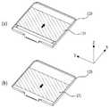
도 1은 본 발명의 제 1 예에 따른 접이식 디스플레이 장치에 있어서, 펼쳐진 디스플레이 패널을 개략적으로 나타내는 도면이다.
도 2는 도 1은 본 발명의 제 1 예에 따른 접이식 디스플레이 장치에 있어서, 접혀진 디스플레이 패널을 개략적으로 나타내는 도면이다.
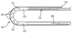
도 3은 도 1에 도시된 접이식 디스플레이 장치의 분해 사시도이다.
도 4는 도 3에 도시된 링크 바를 설명하기 위한 도면이다.
도 5는 도 3 및 도 4에 도시된 제 1 링크 바의 회전을 설명하기 위한 도면이다.
도 6은 도 3에 도시된 슬라이딩 어셈블리를 설명하기 위한 단면도이다.
도 7은 도 3 및 도 6에 도시된 슬라이더의 슬라이딩을 설명하기 위한 도면이다.
도 8은 도 2 및 도 3에 도시된 슬라이딩 어셈블리의 변형 예를 설명하기 위한 도면이다.
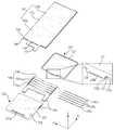
도 9는 본 발명의 제 2 예에 따른 접이식 디스플레이 장치에 있어서, 접혀진 디스플레이 패널을 나타내는 도면이다.
도 10은 본 발명의 제 3 예에 따른 접이식 디스플레이 장치의 분해 사시도이다.
도 11은 도 10에 도시된 슬라이딩 어셈블리를 설명하기 위한 분해 사시도이다.
도 12는 도 10에 도시된 슬라이더와 가이더부 간의 연결 구조를 설명하기 위한 단면도이다.
도 13은 본 발명의 제 3 예에 따른 접이식 디스플레이 장치에서, 디스플레이 패널의 펼침시 또는 접힘시 슬라이딩 어셈블리의 슬라이딩을 설명하기 위한 도면이다.
도 14는 본 발명의 제 4 예에 따른 접이식 디스플레이 장치의 개략적으로 나타내는 도면이다.
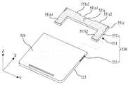
도 15는 본 발명의 제 4 예에 따른 접이식 디스플레이 장치의 분해 사시도이다.
도 16은 본 발명의 제 4 예에 따른 접이식 디스플레이 장치에서, 디스플레이 패널의 펼침시 또는 접힘시 디스플레이 패널의 에지 벤딩 표시 영역을 설명하기 위한 도면이다.1 is a view schematically showing an unfolded display panel in a folding display device according to a first example of the present invention.
FIG. 2 is a view schematically illustrating a folded display panel in a folding display device according to a first example of the present invention.
3 is an exploded perspective view of the foldable display device shown in FIG. 1.
FIG. 4 is a diagram for explaining the link bar illustrated in FIG. 3.
FIG. 5 is a diagram for describing rotation of the first link bar illustrated in FIGS. 3 and 4.
6 is a cross-sectional view for describing the sliding assembly illustrated in FIG. 3.
FIG. 7 is a diagram for describing sliding of the slider illustrated in FIGS. 3 and 6.
FIG. 8 is a view for explaining a modified example of the sliding assembly illustrated in FIGS. 2 and 3.
9 is a view illustrating a folded display panel in the folding display device according to the second example of the present invention.
10 is an exploded perspective view of a foldable display device according to a third example of the present invention.
FIG. 11 is an exploded perspective view illustrating the sliding assembly shown in FIG. 10.
FIG. 12 is a cross-sectional view illustrating a connection structure between the slider and the guider unit illustrated in FIG. 10.
FIG. 13 is a view for explaining sliding of a sliding assembly when the display panel is unfolded or folded in the foldable display device according to the third example of the present invention.
14 is a schematic view of a foldable display device according to a fourth example of the present invention.
15 is an exploded perspective view of a foldable display device according to a fourth example of the present invention.
FIG. 16 is a view illustrating an edge bending display area of a display panel when the display panel is unfolded or folded when the foldable display device according to a fourth example of the present invention.
본 명세서에서 서술되는 용어의 의미는 다음과 같이 이해되어야 할 것이다.The meaning of the terms described herein will be understood as follows.
단수의 표현은 문맥상 명백하게 다르게 정의하지 않는 한 복수의 표현을 포함하는 것으로 이해되어야 하고, "제 1", "제 2" 등의 용어는 하나의 구성요소를 다른 구성요소로부터 구별하기 위한 것으로, 이들 용어들에 의해 권리범위가 한정되어서는 아니 된다. "포함하다" 또는 "가지다" 등의 용어는 하나 또는 그 이상의 다른 특징이나 숫자, 단계, 동작, 구성요소, 부분품 또는 이들을 조합한 것들의 존재 또는 부가 가능성을 미리 배제하지 않는 것으로 이해되어야 한다. "상에"라는 용어는 어떤 구성이 다른 구성의 바로 상면에 형성되는 경우 뿐만 아니라 이들 구성들 사이에 제3의 구성이 개재되는 경우까지 포함하는 것을 의미한다.Singular expressions should be understood to include plural expressions unless the context clearly indicates otherwise, and the terms “first”, “second”, and the like are intended to distinguish one component from another. The scope of the rights shall not be limited by these terms. It is to be understood that the term "comprises" or "having" does not preclude the existence or addition of one or more other features or numbers, steps, operations, components, parts or combinations thereof. The term " on " means to include not only when a configuration is formed directly on top of another configuration but also when a third configuration is interposed between these configurations.
이하에서는 본 발명에 따른 접이식 디스플레이 장치의 바람직한 예를 첨부된 도면을 참조하여 상세히 설명한다. 각 도면의 구성요소들에 참조부호를 부가함에 있어서, 동일한 구성요소들에 대해서는 비록 다른 도면상에 표시되더라도 가능한 한 동일한 부호를 가질 수 있다. 또한, 본 발명을 설명함에 있어, 관련된 공지 구성 또는 기능에 대한 구체적인 설명이 본 발명의 요지를 흐릴 수 있다고 판단되는 경우에는 그 상세한 설명은 생략할 수 있다.Hereinafter, with reference to the accompanying drawings, a preferred example of a folding display device according to the present invention will be described in detail. In adding reference numerals to components of each drawing, the same components may have the same reference numerals as much as possible even though they are shown in different drawings. In addition, in describing the present invention, when it is determined that the detailed description of the related well-known configuration or function may obscure the gist of the present invention, the detailed description may be omitted.
도 1은 본 발명의 제 1 예에 따른 접이식 디스플레이 장치에 있어서, 펼쳐진 디스플레이 패널을 개략적으로 나타내는 도면이고, 도 2는 도 1은 본 발명의 제 1 예에 따른 접이식 디스플레이 장치에 있어서, 접혀진 디스플레이 패널을 개략적으로 나타내는 도면이며, 도 3은 도 1에 도시된 접이식 디스플레이 장치의 분해 사시도이다.1 is a view schematically showing an unfolded display panel in a folding display device according to a first example of the present invention, and FIG. 2 is a view of a folded display panel in a folding display device according to a first example of the present invention. 3 is an exploded perspective view of the folding display device shown in FIG. 1.
도 1 내지 도 3을 참조하면, 본 발명의 제 1 예에 따른 접이식 디스플레이 장치는 디스플레이 패널(110), 제 1 하우징(120), 제 2 하우징(130), 링크 어셈블리(140), 및 슬라이딩 어셈블리(150)를 포함한다.1 to 3, a foldable display device according to a first example of the present invention includes a
상기 디스플레이 패널(110)은 플렉서블 기판을 이용한 플렉서블 디스플레이 패널이 될 수 있다. 일 예로서, 상기 디스플레이 패널(110)은 플렉서블 유기 발광 디스플레이 패널(Flexible Organic Light Emitting Display Panel), 플렉서블 전기 영동 디스플레이 패널(Flexible Electrophoretic Display Panel), 플렉서블 액정 디스플레이 패널(Flexible Liquid Crystal Display Panel), 또는 플렉서블 전자 습윤 디스플레이 패널(Flexible Electro-Wetting Display Panel) 등이 될 수 있다.The
상기 디스플레이 패널(110)은 액티브 매트릭스 형태의 화소 어레이를 갖는 플렉서블 화소 어레이 기판, 및 화소 어레이를 보호하는 봉지 부재를 포함할 수 있다.The
상기 플렉서블 화소 어레이 기판은 플라스틱 재질로 이루어지거나 금속 포일(Foil)로 이루어질 수 있다. 예를 들어, 상기 플라스틱 재질의 플렉서블 화소 어레이 기판은 PI(Polyimide), PET(Polyethyleneterephthalate), PEN(Polyethylenapthanate), PC(Polycarbonate), PNB(Polynorborneen), 및 PES(Polyethersulfone) 중 어느 하나의 재질로 이루어질 수 있다.The flexible pixel array substrate may be made of a plastic material or a metal foil. For example, the flexible pixel array substrate made of plastic may be made of any one of polyimide (PI), polyethylene terephthalate (PET), polyethyleneenapthanate (PEN), polycarbonate (PC), polynorborneen (PNB), and polyethersulfone (PES). Can be.
상기 화소 어레이는 복수의 게이트 라인과 복수의 데이터 라인의 교차에 의해 마련되는 화소 영역마다 형성된 복수의 화소를 포함한다. 상기 화소는 영상 신호에 대응되는 영상을 표시하는 표시 소자를 포함하여 이루어진다. 여기서, 표시 소자는 유기 발광 소자, 액정 표시 소자, 전기 영동 소자, 또는 전자 습윤 표시 소자 등이 될 수 있다.The pixel array includes a plurality of pixels formed for each pixel area provided by the intersection of the plurality of gate lines and the plurality of data lines. The pixel includes a display element for displaying an image corresponding to the image signal. Here, the display element may be an organic light emitting element, a liquid crystal display element, an electrophoretic element, or an electrowetting display element.
상기 표시 소자가 유기 발광 소자 또는 전기 영동 소자일 경우, 일 에에 따른 봉지 부재는 화소 어레이를 덮도록 플렉서블 기판 상에 형성되는 것으로, 플렉서블 봉지 기판 또는 봉지층이 될 수 있다. 상기 표시 소자가 액정 표시 소자, 전자 습윤 표시 소자, 또는 전기 영동 소자일 경우, 다른 예에 따른 봉지 부재는 화소에 대응되는 컬러 필터를 포함하는 플렉서블 컬러필터 기판이 될 수 있다.When the display device is an organic light emitting device or an electrophoretic device, the encapsulation member may be formed on the flexible substrate to cover the pixel array, and may be a flexible encapsulation substrate or an encapsulation layer. When the display device is a liquid crystal display device, an electrowetting display device, or an electrophoretic device, the encapsulation member according to another example may be a flexible color filter substrate including a color filter corresponding to a pixel.
추가적으로, 상기 디스플레이 패널(110)은 봉지 부재에 부착된 편광 필름을 더 포함하여 이루어질 수도 있으나, 상기 편광 필름은 디스플레이 패널(110)의 유연성을 위해 생략 가능하다.In addition, the
상기 디스플레이 패널(110)은 상기 복수의 화소로 이루어진 화소 어레이에 의해 영상을 표시하는 표시 영역(112)을 포함한다. 상기 표시 영역(112)은 제 1 표시 영역(112a), 제 2 표시 영역(112b), 및 벤딩 표시 영역(112c)으로 구분될 수 있다.The
상기 제 1 표시 영역(112a)은 표시 영역(112) 중 상기 벤딩 표시 영역(112c)의 일측에 위치하는 디스플레이 패널(110)의 제 1 영역(예를 들어, 상측 영역)으로 정의될 수 있고, 상기 제 1 표시 영역(112a)은 표시 영역(112) 중 상기 벤딩 표시 영역(112c)의 타측에 위치하는 디스플레이 패널(110)의 제 2 영역(예를 들어, 하측 영역)으로 정의될 수 있다.The
상기 디스플레이 패널(110)이 평면 상태로 펼쳐질 경우, 제 1 표시 영역(112a)과 제 2 표시 영역(112b) 및 벤딩 표시 영역(112c)은 하나의 표시 영역(112)을 구성함으로써 상대적으로 넓은 화면을 제공한다.When the
상기 디스플레이 패널(110)이 벤딩 표시 영역(112c)을 기준으로 설정된 곡률로 벤딩될 경우, 상기 표시 영역(112)에는 영상이 표시되지 않는다.When the
상기 디스플레이 패널(110)은 제 1 영역 또는 제 2 영역의 가장자리 부분으로부터 일정한 폭과 길이를 가지도록 연장된 신호 인가부(114)를 포함한다. 상기 신호 인가부(114)에는 화소 어레이에 형성된 신호 배선과 연결되는 링크 라인들이 형성되어 있다. 이러한 신호 인가부(114)는 제 2 하우징(130)을 통과하여 제 2 하우징(130)의 후면 쪽으로 벤딩됨으로써 제 2 하우징(130)의 후면에 배치되는 시스템 구동부(200)에 연결된다. 상기 신호 인가부(114)에는 시스템 구동부(200)로부터 제공되는 화소 구동 신호와 데이터 신호에 기초하여 표시 영역(112)에 형성된 화소를 구동하기 위한 구동 집적 회로(116)가 실장되어 있다.The
이와 같은, 상기 디스플레이 패널(110)은 플렉서블 지지 플레이트(105)에 부착될 수도 있다. 상기 플렉서블 지지 플레이트(105)는 디스플레이 패널(110)의 후면 전체에 부착됨으로써 플렉서블한 디스플레이 패널(110)을 편평한 상태로 유지시키는 역할을 한다. 상기 플렉서블 지지 플레이트(105)는 상기 플렉서블 화소 어레이 기판의 플렉서블 특성에 따라 생략될 수도 있다.As such, the
한편, 본 발명의 제 1 예에 따른 접이식 디스플레이 장치는 사용자의 터치를 이용한 사용자 인터페이스를 위해 터치 스크린(미도시)을 더 포함하여 구성될 수 있으며, 상기 터치 스크린은 디스플레이 패널(110) 상에 부착되거나 상기 화소 어레이의 형성 공정과 함께 디스플레이 패널(110)에 내장될 수 있다.Meanwhile, the foldable display device according to the first example of the present invention may further include a touch screen (not shown) for a user interface using a user's touch, and the touch screen is attached to the
상기 제 1 하우징(120)은 상기 디스플레이 패널(110)의 제 1 영역, 즉 제 1 표시 영역(112a)과 중첩되는 상기 디스플레이 패널(110)의 제 1 측 후면을 이동 가능하게 지지한다. 이를 위해, 일 예에 따른 제 1 하우징(120)은 바닥면(121), 측벽들(123), 제 1 링크 연결부(125), 및 회전 구속 돌기(127)를 포함할 수 있다.The
상기 바닥면(121)은 상기 디스플레이 패널(110)의 제 1 측 후면을 지지한다. 이때, 상기 디스플레이 패널(110)의 제 1 측 후면은 상기 바닥면(121)과 물리적으로 결합되지 않고, 상기 바닥면(121) 상에 이동 가능하게 배치된다.The
상기 측벽들(123)은 상기 바닥면(121)의 상면 가장자리 부분에 수직하게 형성되어 상기 바닥면(121)에 지지된 상기 디스플레이 패널(110)의 제 1 영역 측면들을 둘러싼다. 이러한, 상기 측벽들(123)은 상기 바닥면(121) 상에 배치된 상기 디스플레이 패널(110)을 외부 충격 등으로부터 보호하면서, 상기 디스플레이 패널(110)과 상기 슬라이딩 어셈블리(140) 각각이 원활하게 이동될 수 있도록 가이드하는 역할을 한다.The
상기 제 1 링크 연결부(125)는 상기 링크 어셈블리(140)의 제 1 측에 인접한 상기 제 1 하우징(120)의 내측벽(123a)으로부터 일정한 폭과 길이를 가지도록 돌출되어 상기 링크 어셈블리(140)의 제 1 측에 연결된다. 예를 들어, 상기 제 1 링크 연결부(125)는 상기 내측벽(123a)의 양 가장자리 부분을 제외한 나머지 부분으로부터 돌출된다.The first
상기 제 1 링크 연결부(125)에는 제 1 샤프트 삽입홀(125a) 및 제 1 중공부(125b)가 형성되어 있다. 상기 제 1 샤프트 삽입홀(125a)은 상기 제 1 링크 연결부(125)의 길이 방향(Y)을 따라 상기 제 1 링크 연결부(125)를 관통하여 형성된다. 상기 제 1 중공부(125b)는 상기 제 1 링크 연결부(125)의 돌출 방향(X)을 따라 일정한 면적을 가지도록 상기 제 1 링크 연결부(125)를 관통하도록 형성되어 상기 제 1 하우징(120)의 후면에 마련된 회로 배치홈(미도시)과 연통된다.A first
상기 회전 구속 돌기(127)는 상기 제 1 링크 연결부(125)의 양측면 각각에 인접한 상기 제 1 하우징(120)의 내측벽(123a) 상측면으로부터 돌출되어 상기 링크 어셈블리(140)의 회전을 구속함으로써 상기 링크 어셈블리(140)가 설정된 최대 회전 각도 이상으로 회전되지 않도록 한다. 이를 위해, 상기 회전 구속 돌기(127)는 직각 삼각 형태의 단면을 갖도록 상기 제 1 하우징(120)의 내측벽(123a)에 형성되되, 경사면이 상기 링크 어셈블리(140)의 회전을 구속하도록 일정한 곡률을 갖도록 형성된다. 상기 회전 구속 돌기(127)의 돌출 길이는 디스플레이 패널(110)의 접힘시 형성되는 벤딩 표시 영역(112c)의 곡률 크기에 대응되도록 설정된다.The
부가적으로, 상기 제 1 하우징(120)의 후면은 제 1 후면 커버(160)에 의해 덮인다. 상기 제 1 후면 커버(160)는 상기 제 1 하우징(120)의 후면에 수납되는 디스플레이 패널의 구동에 필요한 반도체 부품을 덮도록 상기 제 1 하우징(120)의 후면에 결합된다.In addition, the rear surface of the
상기 제 1 하우징(120)에 결합된 상기 디스플레이 패널(110)의 제 1 표시 영역(112a)에 인접한 주변 영역은 제 1 전면 커버(미도시)에 의해 덮일 수 있으며, 제 1 전면 커버는 제 1 표시 영역(112a)과 제 1 표시 영역(112a)에 인접한 벤딩 영역(112c)을 제외한 나머지 제 1 표시 영역(112a)의 좌우측 가장자리 부분과 상측 가장자리 부분만을 덮을 수 있는 형태를 가지도록 형성되어 상기 제 1 하우징(120)과 결합된다.A peripheral area adjacent to the
상기 제 2 하우징(130)은 상기 디스플레이 패널(110)의 제 2 영역, 즉 제 2 표시 영역(112b)과 중첩되는 상기 디스플레이 패널(110)의 제 2 측 후면을 지지한다. 이때, 상기 제 2 하우징(130)은 상기 디스플레이 패널(110)의 제 2 측 후면과 물리적으로 결합된다. 이를 위해, 일 예에 따른 제 2 하우징(130)은 바닥면(131), 측벽들(133), 및 제 2 링크 연결부(135)를 포함한다.The
상기 바닥면(131)은 상기 디스플레이 패널(110)의 제 2 영역 후면을 지지한다. 이때, 상기 디스플레이 패널(110)의 제 2 측 후면은 도시하지 않은 투명 접착제, 접착 시트, 또는 양면 테이프에 의해 상기 바닥면(131)과 물리적으로 결합된다.The
상기 바닥면(131)에는 상기 신호 인가부(114)가 관통하는 회로 통과홀(131a)이 형성되어 있다. 이에 따라, 상기 신호 인가부(114)는 상기 회로 통과홀(131a)에 삽입된 후, 일정한 곡률로 벤딩되어 상기 제 2 하우징(130)의 후면에 배치된다.The
상기 측벽들(133)은 상기 링크 어셈블리(140)와 연결되는 상기 바닥면(131)의 내측부를 제외한 나머지 바닥면(131)의 상면 가장자리 부분에 수직하게 형성된다. 이러한, 상기 측벽들(133)은 상기 바닥면(131)에 물리적으로 결합된 상기 디스플레이 패널(110)의 제 2 영역 측면들을 둘러쌈으로써 외부 충격 등으로부터 디스플레이 패널(110)을 보호한다.The
상기 제 2 링크 연결부(135)는 상기 링크 어셈블리(140)의 제 2 측에 인접한 상기 제 2 하우징(130)의 내측벽(133a)으로부터 일정한 폭과 길이를 가지도록 오목하게 형성되어 상기 링크 어셈블리(140)의 제 2 측에 연결된다. 예를 들어, 상기 제 2 링크 연결부(135)는 상기 제 2 하우징(130)의 길이 방향(X)을 따라 상기 내측벽(133a)의 양 가장자리 부분을 제외한 나머지 부분으로부터 일정한 깊이로 오목하게 형성된다.The second
상기 제 2 하우징(130)의 내측벽(133a) 중 상기 제 2 링크 연결부(135)가 형성되지 않으면서 상기 링크 어셈블리(140)와 마주하는 나머지 내측벽(133a) 상면 모서리 부분을 일정한 곡률로 라운딩될 수 있다.Of the
상기 제 2 링크 연결부(135)에는 제 2 샤프트 삽입홀(135a) 및 제 2 중공부(미도시)가 형성되어 있다. 상기 제 2 샤프트 삽입홀(135a)은 상기 제 2 링크 연결부(135)를 사이에 두고 서로 나란한 상기 제 2 하우징(130)의 내측벽(133a)을 관통하도록 상기 내측벽(133a)의 길이 방향(Y)을 따라 형성된다.A second
상기 제 2 중공부는 상기 제 2 하우징(130)의 길이 방향(X)을 따라 일정한 면적으로 가지도록 상기 제 2 링크 연결부(135)를 관통하도록 형성된다. 상기 제 2 중공부는 상기 제 2 하우징(130)의 후면에 마련된 회로 배치홈(미도시)과 연통된다. 이러한, 제 2 중공부는 제 1 및 제 2 하우징(120, 130) 각각의 후면에 배치된 시스템 구동부(200) 사이를 연결하는 케이블 및/또는 신호 전송 필름 등이 통과하는 통로 역할을 한다.The second hollow part is formed to penetrate the second
부가적으로, 상기 제 2 하우징(130)의 후면은 제 2 후면 커버(170)에 의해 덮인다. 상기 제 2 후면 커버(170)는 상기 제 2 하우징(130)의 후면에 수납되는 시스템 구동부(200), 및 배터리(미도시)를 덮도록 상기 제 2 하우징(130)의 후면에 결합된다.Additionally, the rear surface of the
상기 제 2 하우징(130)에 결합된 상기 디스플레이 패널(110)의 제 2 표시 영역(112b)에 인접한 주변 영역은 제 2 전면 커버(미도시)에 의해 덮일 수 있으며, 제 2 전면 커버는 제 2 표시 영역(112b)과 제 2 표시 영역(112b)에 인접한 벤딩 영역(112c)을 제외한 나머지 제 2 표시 영역(112b)의 좌우측 가장자리 부분, 상측 가장자리 부분, 신호 인가부(114), 및 구동 집적 회로(116)를 덮을 수 있는 형태를 가지도록 형성되어 상기 제 2 하우징(130)과 결합된다.A peripheral area adjacent to the
상기 링크 어셈블리(140)는 상기 제 1 및 제 2 하우징(120, 130) 사이에 연결되어 상기 디스플레이 패널(110)의 펼침과 접힘을 가이드하고, 펼쳐지거나 접혀진 디스플레이 패널(110)의 벤딩 표시 영역(112c)을 지지한다. 이를 위해, 일 예에 따른 링크 어셈블리(140)는 제 1 링크 바(141), 제 2 링크 바(143), 및 복수의 중간 링크 바(145)를 포함할 수 있다.The
상기 제 1 링크 바(141)는 상기 제 1 하우징(120)에 회전 가능하게 연결된다. 이를 위해, 일 예에 따른 제 1 링크 바(141)는, 도 4 및 도 5에 도시된 바와 같이, 몸체(310), 한 쌍의 가이드 측벽(320), 전방 연결부(330), 후방 연결부(340), 전방 샤프트 홀(350), 후방 샤프트 홀(360), 및 스토퍼(370)를 포함한다.The
상기 몸체(310)는 상기 제 1 하우징(120)의 내측벽(123a)과 나란하도록 사각 단면의 바 형태로 형성되어 디스플레이 패널(110)의 벤딩 표시 영역(112b)에 중첩되는 디스플레이 패널(110)의 후면을 지지한다. 이때, 상기 몸체(310)의 전방 측면(310a)은 상기 제 1 하우징(120)의 내측벽(123a)과 직접적으로 대향되는 수직면으로 이루어진다. 상기 몸체(310)의 전방 측면(310a)과 상면 사이의 상측 모서리 부분은 제 1 링크 바(141)의 제 1 방향 회전을 위해 일정한 곡률를 가지는 라운딩부(RP)로 이루어진다.The
상기 한 쌍의 가이드 측벽(320)은 상기 몸체(310)의 길이 방향(Y)을 기준으로, 몸체(310)의 양측 가장자리 부분으로부터 일정한 높이를 가지도록 수직하게 형성된다. 상기 한 쌍의 가이드 측벽(320)은 디스플레이 패널(110)의 길이 방향(X)을 기준으로, 상기 몸체(310)의 상면에 배치되는 디스플레이 패널(110)의 양측면을 감쌈으로써 디스플레이 패널(110)의 측면이 외부로 노출되지 않도록 하고, 디스플레이 패널(110)의 이동을 가이드하는 역할도 한다.The pair of guide sidewalls 320 are vertically formed to have a constant height from both side edge portions of the
상기 전방 연결부(330)는 상기 제 1 하우징(120)의 제 1 링크 연결부(125)가 삽입되도록 상기 몸체(310)의 전방 측면(310a)으로부터 오목하게 형성된다. 이때, 상기 전방 연결부(330)는 상기 제 1 링크 연결부(125)와 동일한 형태를 가지도록 형성되어 상기 제 1 링크 연결부(125)에 회전 가능하게 연결된다.The front connecting
상기 후방 연결부(340)는 상기 제 2 하우징(130)의 제 2 링크 연결부(135)에 삽입되도록 상기 몸체(310)의 후방 측면(310b)으로부터 돌출된다. 이때, 상기 후방 연결부(340)는 상기 제 2 링크 연결부(135)와 동일한 형태를 가지도록 형성되어 상기 제 2 링크 연결부(135)에 회전 가능하게 연결된다.The
상기 후방 연결부(340)에는 제 2 중공부(342)가 형성되어 있다. 상기 제 2 중공부(342)는 상기 몸체(310)의 폭 방향(X)을 따라 상기 몸체(310)를 관통하도록 형성되어 상기 제 1 하우징(120)의 제 1 중공부(125b)와 연통된다.A second hollow part 342 is formed at the
상기 전방 샤프트 홀(350)은 상기 전방 연결부(330)를 사이에 두고 서로 나란한 상기 몸체(310)의 전방 가장자리 부분에 형성된다. 상기 전방 샤프트 홀(350)은 상기 몸체(310)의 길이 방향(Y)을 따라 상기 몸체(310)의 전방 가장자리 부분을 관통하도록 형성된다.The
상기 후방 샤프트 홀(350)은 상기 몸체(310)의 길이 방향(Y)을 따라 상기 후방 연결부(330)를 관통하도록 형성된다.The
상기 스토퍼(370)는 상기 후방 연결부(340)의 양측면 각각에 인접한 상기 몸체(310)의 후방 측면(310b) 상측면으로부터 돌출되어 인접한 중간 링크 바(145)의 회전을 구속함으로써 인접한 중간 링크 바(145)가 설정된 최대 회전 각도 이상으로 회전되지 않도록 한다. 이를 위해, 상기 스토퍼(370)는 직각 삼각 형태의 단면을 갖도록 상기 몸체(310)의 후방 측면(310b)에 형성되되, 경사면이 상기 인접한 중간 링크 바(145)의 회전을 구속하도록 일정한 곡률을 갖도록 형성된다. 상기 스토퍼(370)의 돌출 길이는 디스플레이 패널(110)의 접힘시 형성되는 벤딩 표시 영역(112c)의 곡률 크기에 대응되도록 설정된다.The
이와 같은, 제 1 링크 바(141)는 상기 전방 샤프트 홀(350)과 상기 제 1 하우징(120)의 제 1 샤프트 삽입홀(125a)에 삽입되는 제 1 샤프트(141a)에 의해 상기 제 1 하우징(120)의 제 1 링크 연결부(125)에 연결된다. 여기서, 제 1 샤프트(141a)는 상기 전방 샤프트 홀(350)과 상기 제 1 샤프트 삽입홀(125a) 간에 걸쳐지도록 삽입 배치됨으로써 서로 연결된 제 1 링크 바(141)와 제 1 링크 연결부(125) 각각을 회전 가능하게 지지함과 아울러 외력에 의해 제 1 링크 바(141)와 제 1 링크 연결부(125)가 분리되거나 휘어지는 것을 방지한다.As such, the
따라서, 상기 제 1 링크 바(141)는 상기 제 1 샤프트(141a)를 회전축으로 하여 수평선(HL)을 기준으로 설정된 각도(θ)만큼 회전 가능하게 된다. 예를 들어, 디스플레이 패널(110)의 접힘시 제 1 링크 바(141)는, 전방 측면(310a)의 상부 모서리 부분에 형성된 라운딩부(RP)가 상기 제 1 하우징(120)의 회전 구속 돌기(127)에 물리적으로 접촉될 때까지 평면 상태(HL)로부터 설정된 각도(θ)만큼 제 1 방향(예를 들어, 시계 방향)으로 회전함으로써 디스플레이 패널(110)의 접힘을 가이드한다. 그리고, 디스플레이 패널(110)의 펼침시 제 1 링크 바(141)는, 전방 측면(310a)의 수직면이 제 1 하우징(120)의 내측면(123a)에 물리적으로 접촉될 때까지 회전된 상태로부터 제 2 방향(예를 들어, 반시계 방향)으로 회전함으로써 디스플레이 패널(110)의 펼침을 가이드하고, 펼쳐진 디스플레이 패널(110)의 벤딩 표시 영역(112c)을 지지한다. 특히, 제 1 링크 바(141)는 평면 상태(HL)로 회전된 상태에서는 전방 측면(310a)의 수직면과 제 1 하우징(120)의 내측면(123a)의 물리적인 접촉으로 인하여 더이상 제 2 방향으로 회전되지 않기 때문에 펼쳐진 디스플레이 패널(110)의 벤딩 표시 영역(112c)을 지지함과 아울러 상기 벤딩 표시 영역(112c)이 누르는 힘에 의해 움푹 들어가는 것을 방지한다.Therefore, the
상기 제 2 링크 바(143)는 상기 제 2 하우징(130)에 회전 가능하게 연결된다. 이러한, 제 2 링크 바(143)는, 도 4에 도시된 바와 같이, 몸체(310), 한 쌍의 가이드 측벽(320), 전방 연결부(330), 후방 연결부(340), 전방 샤프트 홀(350), 후방 샤프트 홀(360), 및 스토퍼(370)를 포함하여 구성되는 것으로, 이는 상기 제 2 하우징(130)에 연결되는 것을 제외하고는 전술한 제 1 링크 바(143)와 동일하므로, 이들에 대한 중복 설명은 생략하기로 한다. 이와 같은, 상기 제 2 링크 바(143)는 상기 후방 샤프트 홀(360)과 상기 제 2 하우징(130)의 제 2 샤프트 삽입홀(135a)에 삽입되는 제 2 샤프트(143a)에 의해 상기 제 2 하우징(130)의 제 2 링크 연결부(135)에 연결된다. 이에 따라, 제 2 하우징(130)은 상기 제 2 샤프트(143a)를 회전축으로 하여 수평선(HL)을 기준으로 설정된 각도(θ)만큼 회전 가능하게 된다.The
상기 복수의 중간 링크 바(145) 각각은 상기 제 1 링크 바(141)와 제 2 링크 바(143) 사이에 수평선(HL)을 기준으로 설정된 각도(θ)만큼 회전 가능하도록 상호간에 연결된다. 이러한, 상기 복수의 중간 링크 바(145) 각각은, 도 4에 도시된 바와 같이, 몸체(310), 한 쌍의 가이드 측벽(320), 전방 연결부(330), 후방 연결부(340), 전방 샤프트 홀(350), 후방 샤프트 홀(360), 및 스토퍼(370)를 포함하여 구성되는 것으로, 이는 상기 제 1 링크 바(141)와 제 2 링크 바(143) 사이에서 제 3 샤프트들(145a)에 의해 상호 간에 회전 가능하게 연결되는 것을 제외하고는 전술한 제 1 링크 바(143)와 동일하므로, 이들에 대한 중복 설명은 생략하기로 한다.Each of the plurality of intermediate link bars 145 is connected to each other so as to be rotatable between the
이와 같은, 상기 링크 어셈블리(140)는 제 1 링크 바(141), 제 2 링크 바(143), 및 복수의 중간 링크 바(145) 각각이 스토퍼(370)에 의해 평면 상태(HL)에서 설정된 각도(θ)만큼 회전 가능하도록 상호간에 연결됨으로써 디스플레이 패널(110)의 접힘시 상기 링크 바(141, 143, 145) 각각의 회전 각도에 따라 상기 벤딩 표시 영역(112c)이 설정된 곡률로 접혀지거나 평면 상태로 펼쳐지도록 가이드한다. 이때, 상기 링크 바(141, 143, 145) 각각의 몸체(310)는 일정한 곡률로 접혀지거나 평면 상태로 펼쳐진 벤딩 표시 영역(112c)을 지지함으로써 접혀진 벤딩 표시 영역(112c)의 곡률을 안정적으로 유지시키고, 평면 상태로 펼쳐진 벤딩 표시 영역(112c)을 평면 상태로 유지시킨다.As such, the
다시 도 1 내지 도 3을 참조하면, 상기 슬라이딩 어셈블리(150)는 상기 디스플레이 패널(110)의 제 1 영역과 결합되어 상기 링크 어셈블리(140)의 벤딩에 따라 상기 디스플레이 패널(110)의 제 1 영역을 슬라이딩시킴으로써 상기 디스플레이 패널(110)이 접히거나 펼쳐질 때 발생되는 길이 편차를 보상한다. 즉, 상기 디스플레이 패널(110)의 제 1 및 제 2 영역 각각이 제 1 및 제 2 하우징(120, 130) 각각에 이동되지 않도록 고정될 경우, 상기 디스플레이 패널(110)의 접힘 또는 펼침시 디스플레이 패널(110)에 벤딩 스트레스가 가해지고, 상기 디스플레이 패널(110)과 상기 링크 어셈블리(140)의 곡률 반경의 차이로 인하여 상기 디스플레이 패널(110)의 접힘 또는 펼침시 벤딩 표시 영역(112c)이 주름지거나 벤딩 표시 영역(112c)이 늘어나 손상되는 문제점이 있다. 이러한 문제점을 해결하기 위하여, 상기 슬라이딩 어셈블리(150)는 상기 링크 어셈블리(140)의 벤딩에 연동되어 상기 디스플레이 패널(110)의 제 1 표시 영역(112a)을 슬라이딩시킨다.Referring back to FIGS. 1 to 3, the sliding
일 예에 따른 슬라이딩 어셈블리(150)는, 도 3 및 도 6에 도시된 바와 같이, 슬라이더(151), 및 가이더부(153)를 포함한다.The sliding
상기 슬라이더(151)는 상기 제 1 하우징(120)의 바닥면(121)에 이동 가능하게 배치되어 상기 디스플레이 패널(110)의 제 1 측 후면에 결합된다. 이때, 상기 슬라이더(151)는 평판 형태로 형성되어 접착제, 양면 접착 시트, 또는 양면 테이프 등에 의해 상기 디스플레이 패널(110)의 제 1 측 후면에 결합된다. 상기 슬라이더(151)는 상기 제 1 하우징(120)의 바닥면(121) 쪽으로 돌출된 한 쌍의 레일(151a)을 포함한다. 상기 한 쌍의 레일(151a)은 상기 가이더부(153)에 이동 가능하게 설치된다. 이와 같은, 상기 슬라이더(151)는 상기 링크 어셈블리(140)의 벤딩에 연동되는 벤딩 표시 영역(112c)의 벤딩에 따라 제 1 하우징(120)의 바닥면(121) 상에서 슬라이딩됨으로써 상기 디스플레이 패널(110)의 제 1 영역을 슬라이딩시킨다.The
상기 가이더부(153)는 상기 제 1 하우징(120)에 형성되어 상기 슬라이더(151)의 이동을 가이드한다. 일 예에 따른 가이더부(153)는 한 쌍의 가이드 홀(153a), 및 한 쌍의 플레이트(153b)를 포함한다.The
상기 한 쌍의 가이드 홀(153a)은 제 1 하우징(120)의 바닥면(121)을 관통하도록 나란하게 형성된다. 상기 한 쌍의 가이드 홀(153a)에는 상기 슬라이더(151)에 형성된 상기 한 쌍의 레일(151a)이 각각 삽입된다. 이때, 상기 한 쌍의 레일(151a)의 원활한 이동을 위해, 상기 한 쌍의 가이드 홀(153a)의 폭은 상기 레일(151a)의 폭보다 넓게 형성되는 것이 바람직하다.The pair of
상기 한 쌍의 플레이트(153b) 각각은 상기 제 1 하우징(121)의 하면에 배치되어 상기 한 쌍의 가이드 홀(153a) 각각에 삽입된 상기 한 쌍의 레일(151a) 각각과 결합된다. 상기 한 쌍의 플레이트(153b) 각각은 스크류에 의해 상기 한 쌍의 레일(151a) 각각과 결합됨으로써 상기 가이드 홀(153a)에서 상기 레일(151a)이 이탈되는 것을 방지한다.Each of the pair of
이와 같은, 상기 슬라이딩 어셈블리(150)의 슬라이더(151)는, 디스플레이 패널(110)의 접힘시 도 7의 (a)에 도시된 바와 같이, 상기 링크 어셈블리(140)와 벤딩 표시 영역(112c)이 일정한 곡률로 벤딩됨에 따라 상기 링크 어셈블리(140)를 향하는 방향과 반대되는 방향으로 슬라이딩되어 디스플레이 패널(110)의 제 1 영역을 슬라이딩시킴으로써 디스플레이 패널(110)의 벤딩 표시 영역이 설정된 곡률로 벤딩되도록 한다. 그리고, 상기 슬라이딩 어셈블리(150)의 슬라이더(151)는, 디스플레이 패널(110)의 펼침 도 7의 (b)에 도시된 바와 같이, 일정한 곡률로 벤딩된 상기 링크 어셈블리(140)와 벤딩 표시 영역(112c)이 평면 상태로 펼쳐짐에 따라 상기 링크 어셈블리(140) 쪽으로 슬라이딩되어 디스플레이 패널(110)의 제 1 영역을 슬라이딩시킴으로써 디스플레이 패널(110)의 벤딩 표시 영역이 평면 상태로 펼쳐지도록 한다. 결과적으로, 상기 슬라이딩 어셈블리(150)는 상기 링크 어셈블리(140)와 벤딩 표시 영역(112c)의 벤딩에 연동되어 디스플레이 패널(110)의 제 1 영역을 슬라이딩시킴으로써 디스플레이 패널(110)의 벤딩 표시 영역(112c)이 일정한 곡률로 접혀지거나 평면 상태로 펼쳐지도록 한다.As such, the
도 8은 도 2 및 도 3에 도시된 슬라이딩 어셈블리의 변형 예를 설명하기 위한 도면이다.FIG. 8 is a view for explaining a modified example of the sliding assembly illustrated in FIGS. 2 and 3.
도 8을 도 3과 결부하면, 변형 예에 따른 슬라이딩 어셈블리(150')는 슬라이더(151'), 한 쌍의 슬라이딩 축(152), 및 가이더부(153')를 포함한다.8 and 3, the sliding
상기 슬라이더(151')는 상기 제 1 하우징(120)의 바닥면(121)에 이동 가능하게 배치되어 상기 디스플레이 패널(110)의 제 1 측 후면에 결합된다. 이때, 상기 슬라이더(151')는 평판 형태로 형성되어 접착제, 양면 접착 시트, 또는 양면 테이프 등에 의해 상기 디스플레이 패널(110)의 제 1 측 후면에 결합된다. 이러한, 상기 슬라이더(151')는 상기 링크 어셈블리(140)의 벤딩에 연동되는 벤딩 표시 영역(112c)의 벤딩에 따라 제 1 하우징(120)의 바닥면(121) 상에서 슬라이딩됨으로써 상기 디스플레이 패널(110)의 제 1 영역을 슬라이딩시킨다.The
상기 한 쌍의 슬라이딩 축(152)은 디스플레이 패널(110)의 길이 방향(X)과 나란한 상기 슬라이더(151')의 양측면에 형성되어 상기 가이더부(153')에 이동 가능하게 연결된다. 여기서, 상기 한 쌍의 슬라이딩 축(152)은 상기 슬라이더(151')의 양측면 각각에 일정한 깊이로 삽입 결합되거나 상기 슬라이더(151')의 양측면 각각으로부터 일정한 길이를 가지도록 상기 제 1 하우징(120)의 양측벽(123) 쪽으로 돌출될 수 있다.The pair of sliding
상기 가이더부(153')는 상기 슬라이더(151')의 양측면과 나란한 상기 제 1 하우징(120)의 양측벽(123)에 형성되어 상기 슬라이더(151')의 이동을 가이드한다. 일 예에 따른 가이더부(153')는 한 쌍의 가이드 홀로 이루어질 수 있다.The
상기 한 쌍의 가이드 홀은 일정한 길이를 가지도록 상기 제 1 하우징(120)의 양측벽(123)을 관통하도록 형성될 수 있다. 이러한, 상기 한 쌍의 가이드 홀에는 한 쌍의 슬라이딩 축(152)이 이동 가능하게 삽입 배치된다.The pair of guide holes may be formed to penetrate both
이와 같은, 변형 예에 따른 슬라이딩 어셈블리(150')는, 도 7에 도시된 바와 같이, 상기 링크 어셈블리(140)와 벤딩 표시 영역(112c)의 벤딩에 연동되어 디스플레이 패널(110)의 제 1 영역을 슬라이딩시킴으로써 디스플레이 패널(110)의 벤딩 표시 영역(112c)이 일정한 곡률로 접혀지거나 평면 상태로 펼쳐지도록 한다.As shown in FIG. 7, the sliding
따라서, 변형 예에 따른 슬라이딩 어셈블리(150')를 포함하는 접이식 디스플레이 장치는 한 쌍의 슬라이딩 축(152)이 슬라이더(151')의 측면에 형성되고, 상기 한 쌍의 가이드 홀 역시 제 1 하우징(120)의 측벽에 형성되기 때문에 제 1 하우징(120)의 두께를 저감할 수 있다.Accordingly, in the foldable display device including the sliding assembly 150 'according to the modification, a pair of sliding
도 9는 본 발명의 제 2 예에 따른 접이식 디스플레이 장치에 있어서, 접혀진 디스플레이 패널을 나타내는 도면으로서, 이는 디스플레이 패널의 벤딩 방향을 변경한 것이다. 즉, 도 1 내지 도 8에 도시된 본 발명의 제 1 예에 따른 접이식 디스플레이 장치에서는 상기 링크 어셈블리(140)를 구성하는 링크 바(141, 143, 145) 각각의 회전 방향에 따라 디스플레이 패널(110)의 벤딩 표시 영역(112c)을 기준으로, 제 1 및 제 2 표시 영역(112a, 112b)가 서로 직접적으로 대면되도록 접혀진다. 반면에, 도 9에 도시된 본 발명의 제 2 예에 따른 접이식 디스플레이 장치는 상기 링크 어셈블리(140)를 구성하는 링크 바(141, 143, 145) 각각의 회전 방향이 변경됨으로써 디스플레이 패널(110)의 벤딩 표시 영역(112c)을 기준으로, 제 1 및 제 2 표시 영역(112a, 112b)이 외부 방향으로 접혀진다. 이를 위해, 본 발명의 제 2 예에 따른 접이식 디스플레이 장치는 링크 어셈블리(140')가 상하로 반전된 형태로 형성되는 것을 제외하고는 본 발명의 제 1 예에 따른 접이식 디스플레이 장치와 동일하게 구성된다. 상기 링크 어셈블리(140')는 도 3에 도시된 링크 어셈블리(140)와 동일하게 형성되되 상하로 반전된 형태로 형성되어 제 1 및 제 2 하우징(120, 130) 간에 연결된다.9 is a view illustrating a folded display panel in a folding display device according to a second example of the present invention, in which a bending direction of the display panel is changed. That is, in the foldable display device according to the first example of the present invention illustrated in FIGS. 1 to 8, the
한편, 접혀진 디스플레이 패널(110)의 표시 영역(112)은 외부로 노출되기 때문에 접혀진 상태에서도 상기 디스플레이 패널(110)의 제 1 표시 영역(112a)과 제 2 표시 영역(112b) 및 벤딩 표시 영역(112c)은 각기 다른 표시 영역을 구성하여 각기 다른 화면을 제공할 수 있다. 예를 들어, 접혀진 디스플레이 패널(110)에서, 상기 제 1 및 제 2 표시 영역(112a, 112b)에는 영상이 표시되지 않거나, 서로 동일하거나 다른 영상이 동시 또는 선택적으로 표시될 수 있다. 특히, 접혀진 디스플레이 패널(110)에서, 상기 벤딩 표시 영역(112c)은 보조 화면을 구성하여 사용자 인터페이스를 위한 보조 영상이 표시될 수 있다. 여기서, 상기 보조 영상은 시스템 설정 정보, 배터리 잔량, 무선 통신 감도, 시간 정보, 및 메시지 수신 아이콘 등이 될 수 있다.On the other hand, since the
도 10은 본 발명의 제 3 예에 따른 접이식 디스플레이 장치의 분해 사시도이고, 도 11은 도 10에 도시된 슬라이딩 어셈블리를 설명하기 위한 분해 사시도이며, 도 12는 도 10에 도시된 슬라이더와 가이더부 간의 연결 구조를 설명하기 위한 단면도이다.FIG. 10 is an exploded perspective view of a foldable display device according to a third example of the present invention. FIG. 11 is an exploded perspective view for explaining the sliding assembly shown in FIG. 10, and FIG. It is sectional drawing for demonstrating a connection structure.
도 10 내지 도 12를 참조하면, 본 발명의 제 3 예에 따른 접이식 디스플레이 장치는 디스플레이 패널(510), 제 1 하우징(520), 제 2 하우징(530), 링크 어셈블리(540), 및 슬라이딩 어셈블리(550)를 포함한다.10 to 12, a foldable display device according to a third example of the present invention includes a
상기 디스플레이 패널(510)은 제 1 및 제 2 표시 영역(112a, 112b)과 벤딩 표시 영역(112c)을 포함하되, 제 1 및 제 2 표시 영역(112a, 112b)의 위치가 서로 바뀌는 것을 제외하고는 도 1에 도시된 디스플레이 패널(110)과 동일하므로 이에 대한 중복 설명은 생략하기로 한다.The
상기 제 1 하우징(520)은 상기 디스플레이 패널(510)의 제 1 영역, 즉 제 1 표시 영역(112a)과 중첩되는 상기 디스플레이 패널(510)의 제 1 측 후면에 결합된다. 이를 위해, 일 예에 따른 제 1 하우징(520)은 바닥면(521)과 측벽들(523)을 포함한다.The
상기 바닥면(521)은 상기 디스플레이 패널(510)의 제 1 측 후면에 결합된다. 이때, 상기 바닥면(521)은 도시하지 않은 투명 접착제, 접착 시트, 또는 양면 테이프에 의해 상기 디스플레이 패널(510)의 제 2 측 후면과 물리적으로 결합된다. 상기 바닥면(521)에는 상기 디스플레이 패널(510)의 신호 인가부(114)가 관통하는 회로 통과홀(521a)이 형성되어 있다. 이에 따라, 상기 신호 인가부(114)는 상기 회로 통과홀(521a)에 삽입된 후 일정한 곡률로 벤딩되어 상기 제 1 하우징(520)의 후면에 배치된다.The
상기 측벽들(523)은 제 2 하우징(530)을 향하는 상기 바닥면(521)의 전방 가장자리 부분을 제외한 나머지 하면 좌우측과 후방 가장자리 부분에 수직하게 형성된다. 상기 측벽들(523)은 상기 제 1 하우징(520)의 후면에 상기 슬라이딩 어셈블리(550)의 슬라이딩 공간을 마련함으로써 상기 슬라이딩 어셈블리(550)가 원활하게 슬라이딩(또는 이동)될 수 있도록 가이드하는 역할을 한다. 부가적으로, 상기 측벽들(523)은 상기 바닥면(521) 상에 결합된 상기 디스플레이 패널(510)의 3측면을 둘러싸도록 상기 바닥면(521)의 상면 좌우측과 후방 가장자리 부분으로부터 일정한 높이를 가지도록 추가로 형성될 수 있다.The
상기 제 2 하우징(530)은 상기 디스플레이 패널(510)의 제 2 영역, 즉 제 2 표시 영역(112b)과 중첩되는 상기 디스플레이 패널(510)의 제 2 측 후면을 지지한다. 이러한, 상기 제 2 하우징(530)은 상기 디스플레이 패널(510)의 제 2 측 후면과 물리적으로 결합되는 것을 제외하고는 도 3에 도시된 제 1 하우징(120)과 동일하므로, 이에 대해서는 동일한 도면 부호를 부여하고, 이에 대한 중복 설명은 생략하기로 한다.The
상기 링크 어셈블리(540)는 상기 제 1 및 제 2 하우징(520, 530) 사이에 연결되어 상기 디스플레이 패널(110)의 펼침과 접힘을 가이드하고, 펼쳐지거나 접혀진 디스플레이 패널(110)의 벤딩 표시 영역(112c)을 지지한다. 이를 위해, 일 예에 따른 링크 어셈블리(540)는 제 1 링크 바(541), 제 2 링크 바(543), 및 복수의 중간 링크 바(545)를 포함할 수 있다.The
상기 제 1 링크 바(541)는 상기 제 2 하우징(530)의 상기 제 1 링크 연결부(125)에 회전 가능하게 연결되는 것을 제외하고는 도 3 및 도 4에 도시된 제 1 링크 바(141)와 동일하므로, 이에 대한 중복 설명은 생략하기로 한다. 이러한, 제 1 링크 바(541)는 전방 샤프트 홀(350; 도 4 참조)과 상기 제 2 하우징(530)의 제 1 샤프트 삽입홀(125a)에 삽입되는 제 1 샤프트(141a)에 의해 상기 제 2 하우징(530)의 제 1 링크 연결부(125)에 연결됨으로써 상기 제 1 샤프트(141a)를 회전축으로 하여 수평선(HL)을 기준으로 설정된 각도(θ)만큼 회전 가능하게 된다.The
상기 제 2 링크 바(543)는 상기 슬라이딩 어셈블리(550)에 회전 가능하게 연결된다. 이러한, 상기 제 2 링크 바(543)는 상기 슬라이딩 어셈블리(550)에 연결되는 것을 제외하고는, 도 3 및 도 4에 도시된 제 1 링크 바(141)와 동일하므로, 이에 대한 중복 설명은 생략하기로 한다. 이와 같은, 상기 제 2 링크 바(543)는 상기 후방 샤프트 홀(360; 도 4 참조)과 상기 슬라이딩 어셈블리(550)에 삽입되는 제 2 샤프트(143a)에 의해 상기 슬라이딩 어셈블리(550)에 연결됨으로써 상기 제 2 샤프트(143a)를 회전축으로 하여 수평선(HL)을 기준으로 설정된 각도(θ)만큼 회전 가능하게 된다.The
상기 복수의 중간 링크 바(545) 각각은 상기 제 1 링크 바(541)와 제 2 링크 바(543) 사이에 수평선(HL)을 기준으로 설정된 각도(θ)만큼 회전 가능하도록 상호간에 연결된다. 이러한, 상기 복수의 중간 링크 바(545) 각각은, 도 3 및 도 4에 도시된 제 1 링크 바(141)와 동일하게 구성되어 상기 제 1 링크 바(541)와 제 2 링크 바(543) 사이에서 제 3 샤프트들(145a)에 의해 상호 간에 회전 가능하게 연결되므로, 이들에 대한 중복 설명은 생략하기로 한다.Each of the plurality of intermediate link bars 545 is connected to each other so as to be rotatable between the
이와 같은, 상기 링크 어셈블리(540)는 제 1 링크 바(541), 제 2 링크 바(543), 및 복수의 중간 링크 바(545) 각각이 스토퍼(370)에 의해 평면 상태(HL)에서 설정된 각도(θ)만큼 회전 가능하도록 상호간에 연결됨으로써 디스플레이 패널(510)의 접힘시 상기 링크 바(541, 543, 545) 각각의 회전 각도에 따라 상기 슬라이딩 어셈블리(550)를 슬라이딩시키고, 이를 통해 상기 벤딩 표시 영역(112c)이 상기 슬라이딩 어셈블리(550)의 슬라이딩에 따른 제 2 하우징(530)의 이동에 의해 설정된 곡률로 접혀지거나 평면 상태로 펼쳐지도록 가이드한다.As such, the
상기 슬라이딩 어셈블리(550)는 상기 디스플레이 패널(510)의 제 1 영역과 결합됨과 아울러 상기 제 1 하우징(520)에 이동 가능하게 연결되어 상기 링크 어셈블리(540)의 벤딩에 따라 슬라이딩됨으로써 상기 링크 어셈블리(540)와 제 2 하우징(530)을 슬라이딩시켜 상기 디스플레이 패널(510)이 접히거나 펼쳐질 때 발생되는 길이 편차를 보상한다. 즉, 상기 디스플레이 패널(510)의 제 1 및 제 2 영역 각각이 제 1 및 제 2 하우징(520, 530) 각각에 이동되지 않도록 고정될 경우, 상기 디스플레이 패널(510)의 접힘 또는 펼침시 디스플레이 패널(510)에 벤딩 스트레스가 가해지고, 상기 디스플레이 패널(510)과 상기 링크 어셈블리(540)의 곡률 반경의 차이로 인하여 상기 디스플레이 패널(510)의 접힘 또는 펼침시 벤딩 표시 영역(112c)이 주름지거나 벤딩 표시 영역(112c)이 늘어나 손상되는 문제점이 있다. 이러한 문제점을 해결하기 위하여, 상기 슬라이딩 어셈블리(550)는 상기 링크 어셈블리(540)의 벤딩에 연동되어 슬라이딩되어 상기 링크 어셈블리(540)와 제 2 하우징(530)을 슬라이딩시킴으로써 상기 디스플레이 패널(510)의 제 2 표시 영역(112b)을 슬라이딩시킨다.The sliding
일 예에 따른 슬라이딩 어셈블리(550)는, 도 10 내지 도 12에 도시된 바와 같이, 슬라이더(551), 한 쌍의 슬라이딩 축(552), 및 가이더부(153)를 포함한다.The sliding
상기 슬라이더(551)는 상기 제 1 하우징(520)의 후면에 이동 가능하게 배치되는 것으로, 상기 제 1 하우징(520)의 후면에 마련되는 부품 수납 공간이 최대한 확보될 수 있는 형태를 갖도록 형성될 수 있다. 예를 들어, 상기 슬라이더(551)는 "⊃"자 형태의 평면을 가지도록 형성되는 것으로, 링크 결합부(551a), 한 쌍의 날개부(551b1, 551b2), 및 샤프트 배치 홀(551c)을 포함할 수 있다.The
상기 링크 결합부(551a)는 상기 링크 어셈블리(540)의 제 2 링크 바(543)와 회전 가능하게 연결된다. 상기 링크 결합부(551a)의 측면에는 상기 제 2 링크 바(543)의 후방 결합부(340)가 삽입되는 링크 결합홈(551a1)이 형성되어 있다.The
상기 한 쌍의 날개부(551b1, 551b2) 각각은 상기 링크 결합부(551a)의 길이 방향(Y)을 기준으로, 상기 링크 결합부(551a)의 양 가장자리 부분으로부터 상기 제 1 하우징(520) 쪽으로 일정한 길이를 가지도록 나란하게 형성된다.Each of the pair of wings 551b1 and 551b2 may be disposed from both edge portions of the
상기 샤프트 배치 홀(551c)은 상기 링크 결합홈(551a1)를 사이에 두고 나란한 상기 링크 결합부(551a)의 전방 가장자리 부분(551a2, 551a2)에 형성된다. 상기 샤프트 배치 홀(551c)은 상기 링크 결합부(551a)의 길이 방향(Y)을 따라 상기 링크 결합부(551a)의 전방 가장자리 부분(551a2, 551a2)을 관통하도록 형성된다.The
이와 같은, 상기 슬라이더(551)는 상기 샤프트 배치 홀(551c)과 상기 제 2 링크 바(543)의 후방 샤프트 홀(360)에 삽입되는 제 2 샤프트(143a)에 의해 상기 제 2 링크 바(543)의 후방 결합부(340)에 연결됨으로써 상기 링크 어셈블리(540)의 벤딩에 따라 슬라이딩되게 된다. 여기서, 제 2 샤프트(143a)는 상기 샤프트 배치 홀(551c)과 상기 후방 샤프트 홀(360) 간에 걸쳐지도록 삽입 배치됨으로써 서로 연결된 상기 슬라이더(551)와 제 2 링크 바(543) 각각을 회전 가능하게 지지함과 아울러 외력에 의해 상기 슬라이더(551)와 제 2 링크 바(543)가 분리되거나 휘어지는 것을 방지한다.As such, the
상기 한 쌍의 슬라이딩 축(552)은 디스플레이 패널(110)의 길이 방향(X)과 나란한 상기 슬라이더(551)의 양측면에 형성되어 상기 가이더부(553)에 이동 가능하게 연결된다. 상기 슬라이더(551)의 보다 안정적인 직선 운동을 위해 상기 슬라이더(551)의 양측면 각각에는 상기 복수의 슬라이딩 축(552)이 일정한 간격을 형성될 수도 있다. 이러한, 상기 한 쌍의 슬라이딩 축(552)은 상기 슬라이더(551)의 양측면 각각에 일정한 깊이로 삽입 결합되거나 상기 슬라이더(551)의 양측면 각각으로부터 일정한 길이를 가지도록 상기 제 1 하우징(520)의 양측벽(523) 쪽으로 돌출될 수 있다.The pair of sliding
상기 가이더부(553)는 상기 슬라이더(551)의 양측면과 나란한 상기 제 1 하우징(520)의 양측벽(523)에 형성되어 상기 슬라이더(551)의 이동을 가이드한다. 일 예에 따른 가이더부(553)는 한 쌍의 가이드 홀로 이루어질 수 있다.The
상기 한 쌍의 가이드 홀은 일정한 길이를 가지도록 상기 제 1 하우징(520)의 양측벽(523)을 관통하도록 형성될 수 있다. 이러한, 상기 한 쌍의 가이드 홀에는 한 쌍의 슬라이딩 축(552)이 이동 가능하게 삽입 배치된다.The pair of guide holes may be formed to penetrate both
이와 같은, 상기 슬라이딩 어셈블리(550)는 상기 링크 어셈블리(540)와 벤딩 표시 영역(112c)의 벤딩에 연동되어 상기 링크 어셈블리(540)를 슬라이딩시킴으로써 디스플레이 패널(510)의 제 2 영역에 결합된 제 2 하우징(530)을 슬라이딩시켜 디스플레이 패널(510)의 벤딩 표시 영역(112c)이 일정한 곡률로 접혀지거나 평면 상태로 펼쳐지도록 한다.As such, the sliding
예를 들어, 도 13의 (a)에 도시된 바와 같이, 디스플레이 패널(510)의 펼침시, 상기 링크 어셈블리(540)가 평면 상태로 회전됨에 따라 상기 슬라이딩 어셈블리(550)의 슬라이더(551)는 제 1 하우징(520) 쪽으로 슬라이딩되어 상기 링크 어셈블리(540)와 제 2 하우징(530) 각각을 끌어 당김으로써 디스플레이 패널(510)이 평면 상태로 펼쳐지도록 한다. 이로 인하여, 상기 링크 어셈블리(540)는 평면 상태가 되어 디스플레이 패널(510)의 벤딩 표시 영역(112c)을 지지함으로써 펼쳐진 디스플레이 패널(510)의 벤딩 표시 영역(112c)이 외력에 의해 움푹 들어가는 것을 방지한다.For example, as shown in FIG. 13A, when the
그리고, 도 13의 (b)에 도시된 바와 같이, 디스플레이 패널(510)의 접힘시, 상기 링크 어셈블리(540)가 벤딩됨에 따라 상기 슬라이딩 어셈블리(550)의 슬라이더(551)는 제 2 하우징(530) 쪽으로 슬라이딩(X)되어 상기 링크 어셈블리(540)와 제 2 하우징(530) 각각을 밀음으로써 디스플레이 패널(510)이 설정된 곡률로 접혀지도록 한다. 이로 인하여, 상기 링크 어셈블리(540)는 접혀지는 벤딩 표시 영역(112c)을 지지함으로써 디스플레이 패널(510)이 설정된 곡률로 접혀지도록 가이드한다.And, as shown in FIG. 13B, when the
한편, 본 발명의 제 3 예에 따른 접이식 디스플레이 장치에서, 상기 링크 어셈블리(540)는 회전 방향이 반대가 되도록 상하로 반전된 형태로 형성되어 제 2 하우징(530)과 슬라이딩 어셈블리(550) 간에 연결될 수도 있다. 이 경우, 도 9에 도시된 바와 같이, 디스플레이 패널(510)은 상기 링크 어셈블리(540)의 회전 방향에 따라 디스플레이 패널(110)의 벤딩 표시 영역(112c)을 기준으로, 제 1 및 제 2 표시 영역(112a, 112b)이 외부 방향으로 접히게 된다.Meanwhile, in the foldable display device according to the third example of the present invention, the
이상과 같은, 본 발명의 제 3 예에 따른 접이식 디스플레이 장치는 디스플레이 패널(510)의 접힘 또는 펼침시 상기 슬라이딩 어셈블리(550)의 슬라이딩에 연동되는 상기 링크 어셈블리(540)의 슬라이딩에 따라 디스플레이 패널(510)의 길이 편차가 보상됨으로써 디스플레이 패널(510)의 제 2 영역에 대한 이동 공간을 확보할 필요가 없기 때문에 베젤 폭이 감소하게 된다.As described above, the foldable display device according to the third exemplary embodiment of the present invention has a display panel according to sliding of the
도 14는 본 발명의 제 4 예에 따른 접이식 디스플레이 장치의 개략적으로 나타내는 도면이며, 도 15는 본 발명의 제 4 예에 따른 접이식 디스플레이 장치의 분해 사시도로서, 이는 도 10 내지 도 12에 도시된 본 발명의 제 4 예에 따른 접이식 디스플레이 장치에서 디스플레이 패널과 제 2 하우징의 구조를 변경하여 구성한 것이다. 이에 따라, 이하의 설명에서는 상이한 구성에 대해서만 설명하기로 한다.14 is a schematic view of a foldable display device according to a fourth example of the present invention, and FIG. 15 is an exploded perspective view of the foldable display device according to the fourth example of the present invention, which is illustrated in FIGS. 10 to 12. In the foldable display device according to the fourth embodiment of the present invention, the structure of the display panel and the second housing is changed. Accordingly, in the following description, only different configurations will be described.
먼저, 상기 디스플레이 패널(510)은 에지 벤딩 표시 영역(112d)을 더 포함하여 구성된다.First, the
상기 에지 벤딩 표시 영역(112d)은 전술한 제 2 표시 영역(112b)으로부터 일정한 면적으로 가지도록 연장되고, 제 2 하우징(530)에 일정한 곡률을 가지도록 부착된다. 상기 에지 벤딩 표시 영역(112d)은 디스플레이 패널(510)이 접히거나 펼침시에도 일정한 곡률로 벤딩된 상태를 유지한다.The edge bending
일 예에 따른 에지 벤딩 표시 영역(112d)은, 상기 디스플레이 패널(510)이 평면 상태로 펼쳐질 경우, 제 1 및 제 2 표시 영역(112a, 112b) 및 벤딩 표시 영역(112c)과 함께 하나의 표시 화면을 구성할 수 있다.According to an example, the edge bending
다른 예에 따른 에지 벤딩 표시 영역(112d)은, 도 16에 도시된 바와 같이, 상기 디스플레이 패널(510)이 평면 상태로 펼쳐지거나 접힐 경우, 제 1 및 제 2 표시 영역(112a, 112b) 및 벤딩 표시 영역(112c)과 무관한 보조 화면을 구성하여 사용자 인터페이스를 위한 보조 영상이 표시될 수 있다. 여기서, 상기 보조 영상은 시스템 설정 정보, 배터리 잔량, 무선 통신 감도, 시간 정보, 및 메시지 수신 아이콘 등이 될 수 있다.As illustrated in FIG. 16, when the
다음으로, 상기 제 2 하우징(630)은 상기 디스플레이 패널(510)의 제 2 영역, 즉 제 2 표시 영역(112b)과 에지 벤딩 표시 영역(112d)과 중첩되는 상기 디스플레이 패널(510)의 제 2 측 후면을 지지한다. 이를 위해, 상기 제 2 하우징(530)은 본 발명의 제 4 예에 따른 접이식 디스플레이 장치의 제 2 하우징과 동일하게 구성되되, 상기 에지 벤딩 표시 영역(112d)을 일정한 곡률로 벤딩시키는 에지 벤딩부(532)를 더 포함한다.Next, the second housing 630 has a second area of the
상기 에지 벤딩부(532)는 상기 제 2 하우징(530)의 상측 가장자리 부분으로부터 설정된 곡률을 가지도록 곡면 형태로 형성되어 상기 디스플레이 패널(510)의 에지 벤딩 표시 영역(112d)과 물리적으로 결합된다. 이에 따라, 상기 에지 벤딩 표시 영역(112d)은 상기 에지 벤딩부(532)의 곡률에 대응되는 곡률로 벤딩된 상태로 유지된다.The
이와 같은, 본 발명의 제 4 예에 따른 접이식 디스플레이 장치는 디스플레이 패널(510)의 접힘시에도 외부로 노출되는 상기 에지 벤딩 표시 영역(112d)을 통해 사용자 인터페이스를 위한 보조 영상을 사용자에게 제공할 수 있다.As such, the foldable display device according to the fourth embodiment of the present invention may provide an auxiliary image for a user interface to a user through the edge bending
이상에서 설명한 본 발명은 전술한 실시 예 및 첨부된 도면에 한정되는 것이 아니고, 본 발명의 기술적 사항을 벗어나지 않는 범위 내에서 여러 가지 치환, 변형 및 변경이 가능하다는 것이 본 발명이 속하는 기술 분야에서 통상의 지식을 가진 자에게 있어 명백할 것이다. 그러므로, 본 발명의 범위는 후술하는 특허청구범위에 의하여 나타내어지며, 특허청구범위의 의미 및 범위 그리고 그 등가 개념으로부터 도출되는 모든 변경 또는 변형된 형태가 본 발명의 범위에 포함되는 것으로 해석되어야 한다.The present invention described above is not limited to the above-described embodiments and the accompanying drawings, and it is common in the art that various substitutions, modifications, and changes can be made without departing from the technical matters of the present invention. It will be apparent to those who have the knowledge of. Therefore, the scope of the present invention is represented by the following claims, and it should be construed that all changes or modifications derived from the meaning and scope of the claims and equivalent concepts thereof are included in the scope of the present invention.
110, 510: 디스플레이 패널 120, 520: 제 1 하우징
130, 530: 제 2 하우징 140, 540: 링크 어셈블리
141, 541: 제 1 링크 바 143, 543: 제 2 링크 바
145, 545: 중간 링크 바 150, 550: 슬라이딩 어셈블리
151, 551: 슬라이더 153, 553: 가이더부110, 510:
130, 530:
141, 541:
145 and 545:
151, 551:
Claims (10)
Translated fromKorean상기 디스플레이 패널의 제 1 영역을 지지하는 제 1 하우징;
상기 디스플레이 패널의 제 2 영역에 물리적으로 결합된 제 2 하우징;
상기 제 1 및 제 2 하우징 사이에 연결되고, 펼쳐지거나 접히는 상기 디스플레이 패널의 벤딩 표시 영역을 지지하는 링크 어셈블리;
상기 링크 어셈블리의 벤딩에 따라 상기 디스플레이 패널의 제 1 영역 또는 제 2 영역을 슬라이딩시키는 슬라이딩 어셈블리; 및
상기 제 1 영역 또는 상기 제 2 영역의 가장자리로부터 연장되고, 상기 제 1 하우징 또는 상기 제 2 하우징을 통해 상기 제 1 하우징의 후면 또는 상기 제 2 하우징의 후면 쪽으로 벤딩되어 시스템 구동부에 연결된 신호 인가부를 포함하는, 접이식 디스플레이 장치.A display panel expanded or folded based on the bending display area;
A first housing supporting a first area of the display panel;
A second housing physically coupled to a second area of the display panel;
A link assembly connected between the first and second housings and supporting a bending display area of the display panel that is expanded or folded;
A sliding assembly sliding the first area or the second area of the display panel according to the bending of the link assembly; And
A signal applying unit extending from an edge of the first region or the second region and bent toward the rear surface of the first housing or the rear surface of the second housing through the first housing or the second housing and connected to a system driver; , Folding display device.
상기 링크 어셈블리는,
상기 제 1 하우징에 회전 가능하게 연결된 제 1 링크 바;
상기 제 2 하우징에 회전 가능하게 연결된 제 2 링크 바; 및
상기 제 1 링크 바와 상기 제 2 링크 바 사이에 상호 회전 가능하게 연결된 복수의 중간 링크 바를 포함하는, 접이식 디스플레이 장치.The method of claim 1,
The link assembly,
A first link bar rotatably connected to the first housing;
A second link bar rotatably connected to the second housing; And
And a plurality of intermediate link bars rotatably connected between the first link bar and the second link bar.
상기 슬라이딩 어셈블리는,
상기 디스플레이 패널의 제 1 영역에 물리적으로 결합되고, 상기 링크 어셈블리의 벤딩에 따라 슬라이딩되는 슬라이더; 및
상기 슬라이더의 이동을 가이드하기 위해 상기 제 1 하우징에 제공된 가이더를 포함하는, 접이식 디스플레이 장치.The method of claim 2,
The sliding assembly,
A slider physically coupled to the first area of the display panel and sliding along the bending of the link assembly; And
And a guider provided in the first housing to guide movement of the slider.
상기 슬라이더는 상기 제 1 하우징의 바닥면 쪽으로 돌출된 한 쌍의 레일을 포함하고,
상기 가이더는,
상기 제 1 하우징에 제공되고, 상기 한 쌍의 레일이 각각 삽입되는 한 쌍의 가이드 홀; 및
상기 제 1 하우징의 하면에 배치되고, 상기 한 쌍의 가이드 홀 각각에 삽입된 상기 한 쌍의 레일 각각과 결합된 한 쌍의 플레이트를 포함하는, 접이식 디스플레이 장치.The method of claim 3, wherein
The slider includes a pair of rails protruding toward the bottom surface of the first housing,
The guider is,
A pair of guide holes provided in the first housing and into which the pair of rails are inserted; And
And a pair of plates disposed on a bottom surface of the first housing and coupled to each of the pair of rails inserted into each of the pair of guide holes.
상기 슬라이딩 어셈블리는 상기 제 1 하우징에 이동 가능하게 연결되고,
상기 링크 어셈블리는,
상기 제 2 하우징에 회전 가능하게 연결된 제 1 링크 바;
상기 슬라이딩 어셈블리에 회전 가능하게 연결된 제 2 링크 바; 및
상기 제 1 링크 바와 상기 제 2 링크 바 사이에 상호 회전 가능하게 연결된 복수의 중간 링크 바를 포함하는, 접이식 디스플레이 장치.The method of claim 1,
The sliding assembly is movably connected to the first housing,
The link assembly,
A first link bar rotatably connected to the second housing;
A second link bar rotatably connected to the sliding assembly; And
And a plurality of intermediate link bars rotatably connected between the first link bar and the second link bar.
상기 제 1 하우징은 상기 디스플레이 패널의 제 1 영역과 물리적으로 결합되고,
상기 슬라이딩 어셈블리는,
상기 링크 어셈블리에 회전 가능하게 연결되고, 상기 제 1 하우징에 이동 가능하게 배치되며, 상기 링크 어셈블리의 벤딩에 따라 상기 제 2 하우징을 슬라이딩시키는 슬라이더; 및
상기 슬라이더의 이동을 가이드하기 위해 상기 제 1 하우징에 제공된 가이더를 포함하는, 접이식 디스플레이 장치.The method of claim 5,
The first housing is physically coupled to the first area of the display panel,
The sliding assembly,
A slider rotatably connected to the link assembly and movably disposed in the first housing, the slider sliding the second housing according to the bending of the link assembly; And
And a guider provided in the first housing to guide movement of the slider.
상기 슬라이딩 어셈블리는 상기 슬라이더의 양 측면에 각각 제공된 한 쌍의 슬라이딩 축을 더 포함하고,
상기 가이더는 상기 제 1 하우징의 양측벽에 각각 제공되고 상기 한 쌍의 슬라이딩 축의 슬라이딩을 가이드하는 한 쌍의 가이드 홀을 포함하는, 접이식 디스플레이 장치.The method of claim 6,
The sliding assembly further includes a pair of sliding axes respectively provided on both sides of the slider,
And the guider includes a pair of guide holes respectively provided on both side walls of the first housing and configured to guide sliding of the pair of sliding shafts.
상기 제 1 링크 바와 상기 제 2 링크 바 및 상기 복수의 중강 링크 바 각각은 몸체의 후방 측면의 상측면으로부터 돌출된 스토퍼를 포함하며,
상기 스토퍼는 인접한 링크 바의 최대 회전 각도를 구속하는 스토퍼를 포함하는, 접이식 디스플레이 장치.The method according to any one of claims 2 to 7,
Each of the first link bar and the second link bar and the plurality of mid-strength link bars includes a stopper protruding from an upper side of the rear side of the body,
And the stopper includes a stopper for restraining a maximum rotational angle of an adjacent link bar.
상기 제 2 하우징은 일정한 곡률로 벤딩된 에지 벤딩부를 더 포함하고,
상기 디스플레이 패널은 상기 에지 벤딩부에 물리적으로 결합되어 일정한 곡률로 벤딩된 상태로 유지되는 에지 벤딩 표시 영역을 더 포함하는, 접이식 디스플레이 장치.The method according to any one of claims 5 to 7,
The second housing further includes an edge bending portion bent at a constant curvature,
And the display panel further comprises an edge bending display area physically coupled to the edge bending portion and maintained at a predetermined curvature.
상기 디스플레이 패널의 접힙시, 상기 디스플레이 패널의 에지 벤딩 표시 영역은 상기 제 1 하우징에 덮이지 않고 외부로 노출된, 접이식 디스플레이 장치.The method of claim 9,
When the display panel is folded, the edge bending display area of the display panel is exposed to the outside without being covered by the first housing.
Priority Applications (7)
| Application Number | Priority Date | Filing Date | Title |
|---|---|---|---|
| KR1020140089514AKR102015398B1 (en) | 2014-07-16 | 2014-07-16 | Foldable display apparatus |
| US14/558,442US9164547B1 (en) | 2014-07-16 | 2014-12-02 | Foldable display apparatus |
| GB1612382.0AGB2537774B (en) | 2014-07-16 | 2014-12-05 | Foldable display apparatus |
| GB1421675.8AGB2528339B (en) | 2014-07-16 | 2014-12-05 | Foldable display apparatus |
| CN201410815312.8ACN105321430B (en) | 2014-07-16 | 2014-12-23 | foldable display device |
| TW103145309ATWI555456B (en) | 2014-07-16 | 2014-12-24 | Foldable display apparatus |
| DE102014119711.9ADE102014119711B4 (en) | 2014-07-16 | 2014-12-30 | Foldable display device |
Applications Claiming Priority (1)
| Application Number | Priority Date | Filing Date | Title |
|---|---|---|---|
| KR1020140089514AKR102015398B1 (en) | 2014-07-16 | 2014-07-16 | Foldable display apparatus |
Publications (2)
| Publication Number | Publication Date |
|---|---|
| KR20160009726A KR20160009726A (en) | 2016-01-27 |
| KR102015398B1true KR102015398B1 (en) | 2019-08-29 |
Family
ID=52425525
Family Applications (1)
| Application Number | Title | Priority Date | Filing Date |
|---|---|---|---|
| KR1020140089514AActiveKR102015398B1 (en) | 2014-07-16 | 2014-07-16 | Foldable display apparatus |
Country Status (6)
| Country | Link |
|---|---|
| US (1) | US9164547B1 (en) |
| KR (1) | KR102015398B1 (en) |
| CN (1) | CN105321430B (en) |
| DE (1) | DE102014119711B4 (en) |
| GB (2) | GB2537774B (en) |
| TW (1) | TWI555456B (en) |
Cited By (3)
| Publication number | Priority date | Publication date | Assignee | Title |
|---|---|---|---|---|
| US11899507B2 (en) | 2020-11-04 | 2024-02-13 | Samsung Display Co., Ltd. | Display device |
| US11985777B2 (en) | 2021-05-11 | 2024-05-14 | Samsung Display Co., Ltd. | Display device |
| US12144126B2 (en) | 2020-11-12 | 2024-11-12 | Samsung Display Co., Ltd. | Foldable display device having support structure with multiple layers |
Families Citing this family (101)
| Publication number | Priority date | Publication date | Assignee | Title |
|---|---|---|---|---|
| KR102272355B1 (en)* | 2015-01-19 | 2021-07-05 | 삼성디스플레이 주식회사 | Display apparatus |
| WO2016125985A1 (en)* | 2015-02-06 | 2016-08-11 | Lg Electronics Inc. | Mobile terminal |
| KR102304461B1 (en) | 2015-02-24 | 2021-09-24 | 삼성디스플레이 주식회사 | Foldable display apparatus |
| KR102406091B1 (en)* | 2015-04-01 | 2022-06-10 | 삼성전자주식회사 | Electronic device |
| US11268565B2 (en) | 2015-04-09 | 2022-03-08 | Samsung Electronics Co., Ltd. | Foldable device |
| US10883534B2 (en) | 2015-04-09 | 2021-01-05 | Samsung Electronics Co., Ltd. | Foldable device |
| US10365691B2 (en)* | 2015-04-09 | 2019-07-30 | Samsung Electronics Co., Ltd. | Foldable device |
| KR20160123113A (en)* | 2015-04-15 | 2016-10-25 | 엘지전자 주식회사 | Mobile terminal |
| KR102347817B1 (en)* | 2015-07-02 | 2022-01-10 | 삼성디스플레이 주식회사 | Display apparatus |
| KR102379745B1 (en)* | 2015-07-06 | 2022-03-29 | 삼성디스플레이 주식회사 | Display apparatus |
| CN106557118B (en)* | 2015-09-30 | 2024-07-23 | 联想(北京)有限公司 | Electronic device and flexible device |
| USD828321S1 (en)* | 2015-11-04 | 2018-09-11 | Lenovo (Beijing) Co., Ltd. | Flexible smart mobile phone |
| KR102421579B1 (en)* | 2015-11-16 | 2022-07-18 | 삼성디스플레이 주식회사 | Foldable display apparatus |
| KR102446267B1 (en)* | 2015-12-23 | 2022-09-22 | 삼성전자주식회사 | Electronic device and its folding device |
| CN105676962B (en)* | 2016-01-11 | 2020-06-23 | 联想(北京)有限公司 | Electronic equipment |
| DE102017100477A1 (en)* | 2016-01-11 | 2017-07-13 | Lenovo (Beijing) Limited | FLEXIBLE ELECTRONIC DEVICE |
| KR102293027B1 (en)* | 2016-02-16 | 2021-08-24 | 동우 화인켐 주식회사 | Foldable touch sensor and manufacturing method therof |
| CN105872138B (en)* | 2016-03-29 | 2019-04-26 | 联想(北京)有限公司 | A kind of electronic equipment |
| KR102559839B1 (en)* | 2016-04-12 | 2023-07-27 | 삼성디스플레이 주식회사 | Display apparatus |
| KR102484505B1 (en) | 2016-06-20 | 2023-01-05 | 엘지디스플레이 주식회사 | Rollable display device |
| KR102520575B1 (en)* | 2016-07-13 | 2023-04-11 | 삼성디스플레이 주식회사 | Display device |
| CN106023816A (en)* | 2016-08-04 | 2016-10-12 | 珠海市魅族科技有限公司 | Flexible display device |
| KR102487504B1 (en)* | 2016-08-30 | 2023-01-12 | 삼성디스플레이 주식회사 | Electronic device and operating method of the same |
| KR102636648B1 (en) | 2016-09-13 | 2024-02-15 | 삼성전자주식회사 | Flexible Display Electronic device |
| KR102614047B1 (en)* | 2016-09-13 | 2023-12-15 | 삼성전자주식회사 | Electronic apparatus comprising flexible display |
| JP2018054042A (en)* | 2016-09-29 | 2018-04-05 | 株式会社ナチュラレーザ・ワン | Hinge device and display device using hinge device |
| KR102631840B1 (en)* | 2016-10-06 | 2024-01-31 | 삼성디스플레이 주식회사 | Expandable display device |
| KR102628024B1 (en) | 2016-10-07 | 2024-01-22 | 삼성디스플레이 주식회사 | Foldable display device |
| KR102545778B1 (en)* | 2016-10-11 | 2023-06-21 | (주)에이유플렉스 | Hinge Structure for Folderable Display Device |
| WO2018070782A1 (en)* | 2016-10-11 | 2018-04-19 | 박현민 | In-folding hinge structure having flexible display panel installed thereon |
| KR102556395B1 (en) | 2016-11-03 | 2023-07-17 | 삼성디스플레이 주식회사 | Display device |
| KR102716181B1 (en) | 2016-11-18 | 2024-10-11 | 삼성디스플레이 주식회사 | Foldable display device |
| KR102753553B1 (en)* | 2016-11-30 | 2025-01-10 | 엘지디스플레이 주식회사 | Foldable Display Device |
| KR102762585B1 (en) | 2016-11-30 | 2025-02-05 | 엘지디스플레이 주식회사 | Foldable display device |
| KR102672832B1 (en)* | 2016-12-30 | 2024-06-05 | 엘지디스플레이 주식회사 | Foldable display device |
| KR102701604B1 (en)* | 2017-02-23 | 2024-09-03 | 삼성전자주식회사 | Out-foldable electronic apparatus and control method thereof |
| CN106847099A (en)* | 2017-04-24 | 2017-06-13 | 京东方科技集团股份有限公司 | Foldable display device |
| CN107102692B (en)* | 2017-04-26 | 2019-08-23 | 京东方科技集团股份有限公司 | Collapsible display device |
| CN112860018B (en)* | 2017-05-19 | 2024-12-27 | 伊英克公司 | Foldable electro-optical display with digitization and touch sensing |
| KR102434719B1 (en)* | 2017-05-31 | 2022-08-19 | 엘지디스플레이 주식회사 | Foldable display apparatus |
| US10015897B1 (en) | 2017-06-21 | 2018-07-03 | Dell Products L.P. | Flexible information handling system display sliding frame |
| US10082839B1 (en) | 2017-06-21 | 2018-09-25 | Dell Products L.P. | Flexible information handling system display hinge and ramp support structure |
| US10120421B1 (en) | 2017-06-21 | 2018-11-06 | Dell Products L.P. | Flexible information handling system display |
| US9964995B1 (en) | 2017-06-21 | 2018-05-08 | Dell Products L.P. | Dynamic antenna orientation with a flexible information handling system display |
| US10082838B1 (en) | 2017-06-21 | 2018-09-25 | Dell Products L.P. | Flexible information handling system display external hinge structure |
| KR102324508B1 (en)* | 2017-06-28 | 2021-11-09 | 엘지디스플레이 주식회사 | Foldable display apparatus |
| CN109215507B (en) | 2017-07-07 | 2021-08-27 | 元太科技工业股份有限公司 | Foldable display device |
| KR101834793B1 (en)* | 2017-07-28 | 2018-03-06 | 엘지디스플레이 주식회사 | Flexible Display and Electronic Device Including the Same |
| US11079807B1 (en)* | 2017-08-03 | 2021-08-03 | Apple Inc. | Friction roller hinge for electronic devices and method for making roller and spacer elements |
| CN107370848B (en)* | 2017-08-25 | 2024-02-20 | Oppo广东移动通信有限公司 | Foldable mobile terminal and its folding mechanism and folding components |
| KR102369318B1 (en)* | 2017-08-30 | 2022-03-02 | 엘지디스플레이 주식회사 | Flexible display device |
| KR102421304B1 (en)* | 2017-09-18 | 2022-07-18 | 삼성디스플레이 주식회사 | Supporting member and display apparatus including the same |
| KR102402183B1 (en)* | 2017-09-29 | 2022-05-27 | 엘지디스플레이 주식회사 | Foldable Display Device |
| CN107644590A (en)* | 2017-10-26 | 2018-01-30 | 武汉华星光电半导体显示技术有限公司 | Center and flexible display apparatus |
| KR102403713B1 (en)* | 2017-10-31 | 2022-05-30 | 엘지디스플레이 주식회사 | Flexible Display |
| KR102456889B1 (en)* | 2017-11-01 | 2022-10-21 | 엘지전자 주식회사 | Flexible frame and flexible display unit having the same |
| MY198924A (en) | 2017-11-28 | 2023-10-02 | Samsung Electronics Co Ltd | Foldable display device |
| KR102408387B1 (en)* | 2017-12-04 | 2022-06-10 | 엘지디스플레이 주식회사 | Display apparatus |
| KR102422072B1 (en)* | 2017-12-04 | 2022-07-18 | 엘지디스플레이 주식회사 | Display apparatus |
| KR102447330B1 (en)* | 2017-12-14 | 2022-09-23 | 엘지디스플레이 주식회사 | foldable display |
| CN109936648B (en) | 2017-12-18 | 2020-08-07 | 华为技术有限公司 | Slewing mechanism and folding terminal |
| US10586943B2 (en) | 2017-12-22 | 2020-03-10 | Sakai Display Products Corporation | Display apparatus and method for attaching display panel |
| KR102442942B1 (en)* | 2017-12-27 | 2022-09-13 | 엘지디스플레이 주식회사 | foldable display |
| CN108230907B (en)* | 2018-01-03 | 2020-03-24 | 上海天马有机发光显示技术有限公司 | Flexible display screen and display device |
| WO2019174248A1 (en)* | 2018-03-12 | 2019-09-19 | 深圳市柔宇科技有限公司 | Bending mechanism and flexible display device |
| CN108447401B (en)* | 2018-03-28 | 2020-06-05 | 武汉华星光电技术有限公司 | Flexible display device and deformation compensation method of flexible display screen |
| US10788861B2 (en) | 2018-03-28 | 2020-09-29 | Wuhan China Star Optoelectronics Technology Co., Ltd. | Flexible display device and deformation compensation method of flexible display screen |
| CN112470097A (en)* | 2018-05-25 | 2021-03-09 | 深圳市柔宇科技股份有限公司 | Flexible display module and flexible terminal |
| KR102540815B1 (en)* | 2018-06-01 | 2023-06-08 | 삼성전자주식회사 | Electronic device including a foldable display |
| JP6588133B2 (en)* | 2018-06-11 | 2019-10-09 | 堺ディスプレイプロダクト株式会社 | Display device and display panel mounting method |
| WO2019237340A1 (en)* | 2018-06-15 | 2019-12-19 | 深圳市柔宇科技有限公司 | Flexible screen dust-proof mechanism, electronic device and fabrication method for flexible screen dust-proof mechanism |
| CN108597380B (en)* | 2018-07-18 | 2023-10-20 | 昆山国显光电有限公司 | display panel |
| KR102512482B1 (en)* | 2018-07-31 | 2023-03-21 | 엘지디스플레이 주식회사 | Foldable Display |
| WO2020051902A1 (en)* | 2018-09-14 | 2020-03-19 | 深圳市柔宇科技有限公司 | Flexible display device |
| JP2020046541A (en)* | 2018-09-19 | 2020-03-26 | レノボ・シンガポール・プライベート・リミテッド | Portable information appliance |
| TWI670696B (en) | 2018-09-28 | 2019-09-01 | 元太科技工業股份有限公司 | Foldable display device |
| TWI693500B (en)* | 2018-12-06 | 2020-05-11 | 兆利科技工業股份有限公司 | A hinge module for a foldable type device |
| KR102624839B1 (en) | 2018-12-28 | 2024-01-17 | 삼성디스플레이 주식회사 | Display device |
| KR102709191B1 (en)* | 2018-12-31 | 2024-09-24 | 삼성디스플레이 주식회사 | Foldable display device |
| KR102563626B1 (en)* | 2019-01-09 | 2023-08-04 | 삼성전자 주식회사 | Flexible display and electronic device including the same |
| US10817030B2 (en) | 2019-01-14 | 2020-10-27 | Dell Products L.P. | Portable information handling system flexible display with alternating slide support frame |
| US10928863B2 (en) | 2019-01-14 | 2021-02-23 | Dell Products L.P. | Portable information handling system midframe to sliding frame assembly |
| KR102736380B1 (en)* | 2019-01-16 | 2024-12-02 | 삼성디스플레이 주식회사 | Display device and manufacturing method of the same |
| US10754395B2 (en) | 2019-01-17 | 2020-08-25 | Dell Products L.P. | Multi-axis hinge translation to adjust housing position relative to flexible display position |
| US11023009B2 (en)* | 2019-02-12 | 2021-06-01 | Samsung Display Co., Ltd. | Folding member and display device including the same |
| KR102661194B1 (en)* | 2019-02-15 | 2024-04-29 | 삼성전자 주식회사 | Housing, manufacturing method thereof, and electronic device including the same |
| WO2020209424A1 (en)* | 2019-04-11 | 2020-10-15 | 엘지전자 주식회사 | Flexible display device |
| CN111833725A (en)* | 2019-04-18 | 2020-10-27 | 深圳市柔宇科技有限公司 | Folding device and electronic equipment |
| KR102733499B1 (en)* | 2019-04-29 | 2024-11-26 | 삼성디스플레이 주식회사 | Display device |
| KR102794470B1 (en)* | 2019-05-10 | 2025-04-11 | 삼성전자 주식회사 | Housing, manufacturing method thereof, and electronic device including the same |
| TWI724807B (en)* | 2019-07-24 | 2021-04-11 | 友達光電股份有限公司 | Flexible apparatus |
| EP4071595A4 (en)* | 2019-12-03 | 2023-08-16 | LG Electronics Inc. | Electronic device for providing content and control method therefor |
| US11775017B2 (en)* | 2020-04-03 | 2023-10-03 | Hewlett-Packard Development Company, L.P. | Bendable displays |
| CN113803575B (en)* | 2020-06-12 | 2025-09-16 | Drnc控股公司 | Flexible screen supporting device and intelligent terminal |
| WO2022054996A1 (en)* | 2020-09-14 | 2022-03-17 | 엘지전자 주식회사 | Mobile terminal |
| CN114203028A (en)* | 2020-09-18 | 2022-03-18 | 深圳市柔宇科技股份有限公司 | Foldable structure and electronic equipment |
| KR102274481B1 (en)* | 2020-10-12 | 2021-07-08 | 삼성전자 주식회사 | Electronic device including flexible display |
| CN116324946A (en) | 2020-11-06 | 2023-06-23 | 三星电子株式会社 | Electronic device including flexible display |
| CN114023197B (en)* | 2021-11-22 | 2022-12-06 | 武汉华星光电半导体显示技术有限公司 | Folding display device |
| US11937390B2 (en) | 2021-11-22 | 2024-03-19 | Wuhan China Star Optoelectronics Semiconductor Display Technology Co., Ltd. | Foldable display device |
| CN114697435B (en)* | 2022-06-02 | 2022-10-18 | 荣耀终端有限公司 | Folding assembly and terminal equipment |
Citations (9)
| Publication number | Priority date | Publication date | Assignee | Title |
|---|---|---|---|---|
| JP2011112891A (en) | 2009-11-27 | 2011-06-09 | Kyocera Corp | Portable display device |
| WO2012021525A1 (en) | 2010-08-10 | 2012-02-16 | Aniteal Laboratories | Reconfigurable touch screen computing device |
| US20130010405A1 (en) | 2011-07-06 | 2013-01-10 | Rothkopf Fletcher R | Flexible display devices |
| US20130021762A1 (en) | 2011-07-11 | 2013-01-24 | Polymer Vision B.V. | Flexible display with display support |
| CA2791574A1 (en) | 2011-11-15 | 2013-05-15 | Research In Motion Limited | Handheld electronic device having a flexible display |
| JP2013231982A (en) | 2009-05-02 | 2013-11-14 | Semiconductor Energy Lab Co Ltd | Display device |
| JP2013254021A (en) | 2012-06-05 | 2013-12-19 | Sony Corp | Display device and electronic apparatus |
| US20140029190A1 (en) | 2012-07-25 | 2014-01-30 | Kabushiki Kaisha Toshiba | Electronic device |
| CN103620516A (en) | 2011-06-03 | 2014-03-05 | 微软公司 | Flexible display flexure assembly |
Family Cites Families (32)
| Publication number | Priority date | Publication date | Assignee | Title |
|---|---|---|---|---|
| KR100284342B1 (en)* | 1998-05-30 | 2001-03-02 | 김순택 | Portable Liquid Crystal Device having flexible Liquid Crystal Display |
| JP4190915B2 (en)* | 2003-03-10 | 2008-12-03 | セイコーインスツル株式会社 | Connecting pin for band piece, band and watch |
| US7714801B2 (en)* | 2005-01-05 | 2010-05-11 | Nokia Corporation | Foldable electronic device and a flexible display device |
| US7653422B2 (en)* | 2006-02-28 | 2010-01-26 | Motorola, Inc. | Method and apparatus for a sliding hinge |
| CN101529324B (en)* | 2006-11-06 | 2011-02-02 | 松下电器产业株式会社 | Liquid crystal display device |
| EP2141895B1 (en)* | 2007-03-28 | 2014-09-24 | NEC Corporation | Folding portable device and connecting mechanism |
| JP2010526335A (en)* | 2007-04-25 | 2010-07-29 | ポリマー、ビジョン、リミテッド | Electronic device with flexible display with edge protector |
| US8629841B2 (en) | 2008-04-30 | 2014-01-14 | Apple Inc. | Multi-touch sensor patterns and stack-ups |
| US8539705B2 (en)* | 2008-08-13 | 2013-09-24 | Edward Bullister | Crossfold electronic device |
| KR101542129B1 (en)* | 2008-10-24 | 2015-08-06 | 삼성전자 주식회사 | Input Device For Foldable Display Device And Input Method Thereof |
| US8385055B2 (en)* | 2008-12-26 | 2013-02-26 | Industrial Technology Research Institute | Electric device and display panel thereof |
| KR20110100936A (en)* | 2010-03-05 | 2011-09-15 | 삼성전자주식회사 | Portable terminal having a flexible display element |
| TWM395341U (en) | 2010-08-04 | 2010-12-21 | Micro Star Int Co Ltd | Foldable electronic apparatus |
| KR101273182B1 (en)* | 2011-02-18 | 2013-06-17 | 주식회사 팬택 | Flexible display apparatus and mobile communication terminal using the same |
| EP2511789A1 (en)* | 2011-04-15 | 2012-10-17 | Research In Motion Limited | Flexible mobile computing devices |
| TW201303446A (en)* | 2011-07-01 | 2013-01-16 | Chi Lin Technology Co Ltd | Backlight module |
| US8711566B2 (en)* | 2011-09-02 | 2014-04-29 | Microsoft Corporation | Expandable mobile device |
| KR102050915B1 (en) | 2011-10-10 | 2019-12-02 | 삼성전자주식회사 | Operating method for wireless communication system using improved carrier aggregation technology and device therefor |
| TWI459274B (en)* | 2011-11-28 | 2014-11-01 | Shih Hua Technology Ltd | Touch panel model and method for making the same |
| US8842424B2 (en)* | 2011-11-30 | 2014-09-23 | Nokia Corporation | Joint cover |
| KR101346146B1 (en)* | 2011-12-23 | 2013-12-31 | 주식회사 세네카 | Hinge Module for Flexible Display Device |
| JP5319825B1 (en)* | 2012-05-22 | 2013-10-16 | 株式会社東芝 | Electronics |
| KR20140002243A (en)* | 2012-06-28 | 2014-01-08 | 삼성디스플레이 주식회사 | A flexible display device |
| KR101911047B1 (en)* | 2012-07-25 | 2018-10-24 | 삼성디스플레이 주식회사 | Case and display device |
| US8804349B2 (en)* | 2012-10-19 | 2014-08-12 | Samsung Display Co., Ltd. | Foldable display device |
| KR101986762B1 (en)* | 2012-10-19 | 2019-06-10 | 삼성디스플레이 주식회사 | Foldable display device |
| EP2728434B1 (en)* | 2012-11-02 | 2017-07-26 | BlackBerry Limited | Support for a flexible display |
| US8971032B2 (en)* | 2012-11-02 | 2015-03-03 | Blackberry Limited | Support for a flexible display |
| US20140123436A1 (en)* | 2012-11-02 | 2014-05-08 | Research In Motion Limited | Support for a flexible display |
| US9348362B2 (en)* | 2013-02-08 | 2016-05-24 | Samsung Electronics Co., Ltd. | Flexible portable terminal |
| KR102081932B1 (en)* | 2013-03-21 | 2020-04-14 | 엘지전자 주식회사 | Display device and method for controlling the same |
| WO2015093801A1 (en)* | 2013-12-16 | 2015-06-25 | 주식회사 세네카 | Hinge module for flexible display device |
- 2014
- 2014-07-16KRKR1020140089514Apatent/KR102015398B1/enactiveActive
- 2014-12-02USUS14/558,442patent/US9164547B1/enactiveActive
- 2014-12-05GBGB1612382.0Apatent/GB2537774B/enactiveActive
- 2014-12-05GBGB1421675.8Apatent/GB2528339B/enactiveActive
- 2014-12-23CNCN201410815312.8Apatent/CN105321430B/enactiveActive
- 2014-12-24TWTW103145309Apatent/TWI555456B/enactive
- 2014-12-30DEDE102014119711.9Apatent/DE102014119711B4/enactiveActive
Patent Citations (9)
| Publication number | Priority date | Publication date | Assignee | Title |
|---|---|---|---|---|
| JP2013231982A (en) | 2009-05-02 | 2013-11-14 | Semiconductor Energy Lab Co Ltd | Display device |
| JP2011112891A (en) | 2009-11-27 | 2011-06-09 | Kyocera Corp | Portable display device |
| WO2012021525A1 (en) | 2010-08-10 | 2012-02-16 | Aniteal Laboratories | Reconfigurable touch screen computing device |
| CN103620516A (en) | 2011-06-03 | 2014-03-05 | 微软公司 | Flexible display flexure assembly |
| US20130010405A1 (en) | 2011-07-06 | 2013-01-10 | Rothkopf Fletcher R | Flexible display devices |
| US20130021762A1 (en) | 2011-07-11 | 2013-01-24 | Polymer Vision B.V. | Flexible display with display support |
| CA2791574A1 (en) | 2011-11-15 | 2013-05-15 | Research In Motion Limited | Handheld electronic device having a flexible display |
| JP2013254021A (en) | 2012-06-05 | 2013-12-19 | Sony Corp | Display device and electronic apparatus |
| US20140029190A1 (en) | 2012-07-25 | 2014-01-30 | Kabushiki Kaisha Toshiba | Electronic device |
Cited By (4)
| Publication number | Priority date | Publication date | Assignee | Title |
|---|---|---|---|---|
| US11899507B2 (en) | 2020-11-04 | 2024-02-13 | Samsung Display Co., Ltd. | Display device |
| US12210392B2 (en) | 2020-11-04 | 2025-01-28 | Samsung Display Co., Ltd. | Display device |
| US12144126B2 (en) | 2020-11-12 | 2024-11-12 | Samsung Display Co., Ltd. | Foldable display device having support structure with multiple layers |
| US11985777B2 (en) | 2021-05-11 | 2024-05-14 | Samsung Display Co., Ltd. | Display device |
Also Published As
| Publication number | Publication date |
|---|---|
| GB2528339B (en) | 2017-07-05 |
| TWI555456B (en) | 2016-10-21 |
| TW201605323A (en) | 2016-02-01 |
| GB201421675D0 (en) | 2015-01-21 |
| GB2528339A (en) | 2016-01-20 |
| CN105321430A (en) | 2016-02-10 |
| KR20160009726A (en) | 2016-01-27 |
| DE102014119711B4 (en) | 2020-06-04 |
| CN105321430B (en) | 2018-04-27 |
| US9164547B1 (en) | 2015-10-20 |
| GB2537774A (en) | 2016-10-26 |
| GB2537774B (en) | 2017-07-05 |
| GB201612382D0 (en) | 2016-08-31 |
| DE102014119711A1 (en) | 2016-01-21 |
Similar Documents
| Publication | Publication Date | Title |
|---|---|---|
| KR102015398B1 (en) | Foldable display apparatus | |
| KR102366515B1 (en) | Foldable display apparatus | |
| US10466747B2 (en) | Foldable display apparatus | |
| KR102366299B1 (en) | Supporting frame for flexible display and flexible display apparatus comprising the same | |
| KR102235171B1 (en) | Foldable display apparatus | |
| KR102244807B1 (en) | Foldable display apparatus | |
| KR102226694B1 (en) | Foldable display apparatus | |
| KR102210047B1 (en) | Foldable display apparatus | |
| US10032391B2 (en) | Foldable display apparatus | |
| US9173287B1 (en) | Foldable display apparatus | |
| KR102333557B1 (en) | Foldable display apparatus | |
| KR20160083608A (en) | Foldable display apparatus |
Legal Events
| Date | Code | Title | Description |
|---|---|---|---|
| PA0109 | Patent application | St.27 status event code:A-0-1-A10-A12-nap-PA0109 | |
| PG1501 | Laying open of application | St.27 status event code:A-1-1-Q10-Q12-nap-PG1501 | |
| P11-X000 | Amendment of application requested | St.27 status event code:A-2-2-P10-P11-nap-X000 | |
| P13-X000 | Application amended | St.27 status event code:A-2-2-P10-P13-nap-X000 | |
| PA0201 | Request for examination | St.27 status event code:A-1-2-D10-D11-exm-PA0201 | |
| PA0302 | Request for accelerated examination | St.27 status event code:A-1-2-D10-D17-exm-PA0302 St.27 status event code:A-1-2-D10-D16-exm-PA0302 | |
| E701 | Decision to grant or registration of patent right | ||
| PE0701 | Decision of registration | St.27 status event code:A-1-2-D10-D22-exm-PE0701 | |
| GRNT | Written decision to grant | ||
| PR0701 | Registration of establishment | St.27 status event code:A-2-4-F10-F11-exm-PR0701 | |
| PR1002 | Payment of registration fee | St.27 status event code:A-2-2-U10-U11-oth-PR1002 Fee payment year number:1 | |
| PG1601 | Publication of registration | St.27 status event code:A-4-4-Q10-Q13-nap-PG1601 | |
| PR1001 | Payment of annual fee | St.27 status event code:A-4-4-U10-U11-oth-PR1001 Fee payment year number:4 | |
| PR1001 | Payment of annual fee | St.27 status event code:A-4-4-U10-U11-oth-PR1001 Fee payment year number:5 | |
| PR1001 | Payment of annual fee | St.27 status event code:A-4-4-U10-U11-oth-PR1001 Fee payment year number:6 | |
| PR1001 | Payment of annual fee | St.27 status event code:A-4-4-U10-U11-oth-PR1001 Fee payment year number:7 |